US5959420A - Heat engine and electric motor torque distribution strategy for a hybrid electric vehicle - Google Patents
Heat engine and electric motor torque distribution strategy for a hybrid electric vehicleDownload PDFInfo
- Publication number
- US5959420A US5959420AUS08/982,047US98204797AUS5959420AUS 5959420 AUS5959420 AUS 5959420AUS 98204797 AUS98204797 AUS 98204797AUS 5959420 AUS5959420 AUS 5959420A
- Authority
- US
- United States
- Prior art keywords
- torque
- engine
- amount
- motor
- determined
- Prior art date
- Legal status (The legal status is an assumption and is not a legal conclusion. Google has not performed a legal analysis and makes no representation as to the accuracy of the status listed.)
- Expired - Lifetime
Links
- 238000000034methodMethods0.000claimsabstract5
- 230000005540biological transmissionEffects0.000claimsdescription49
- 238000007599dischargingMethods0.000claimsdescription5
- 238000010586diagramMethods0.000description10
- 238000004364calculation methodMethods0.000description6
- 239000002803fossil fuelSubstances0.000description6
- 239000000446fuelSubstances0.000description6
- 238000005381potential energyMethods0.000description6
- 230000000694effectsEffects0.000description5
- 230000001172regenerating effectEffects0.000description4
- LFQSCWFLJHTTHZ-UHFFFAOYSA-NEthanolChemical compoundCCOLFQSCWFLJHTTHZ-UHFFFAOYSA-N0.000description3
- OKKJLVBELUTLKV-UHFFFAOYSA-NMethanolChemical compoundOCOKKJLVBELUTLKV-UHFFFAOYSA-N0.000description3
- 238000011217control strategyMethods0.000description3
- 238000004146energy storageMethods0.000description3
- 230000007246mechanismEffects0.000description3
- 230000001133accelerationEffects0.000description2
- 238000013459approachMethods0.000description2
- 230000008901benefitEffects0.000description2
- 238000002485combustion reactionMethods0.000description2
- 230000005611electricityEffects0.000description2
- VNWKTOKETHGBQD-UHFFFAOYSA-NmethaneChemical compoundCVNWKTOKETHGBQD-UHFFFAOYSA-N0.000description2
- 238000012986modificationMethods0.000description2
- 230000004048modificationEffects0.000description2
- 239000004215Carbon black (E152)Substances0.000description1
- 230000004913activationEffects0.000description1
- 230000033228biological regulationEffects0.000description1
- 238000004891communicationMethods0.000description1
- 238000001816coolingMethods0.000description1
- 230000009849deactivationEffects0.000description1
- 239000002283diesel fuelSubstances0.000description1
- 238000010438heat treatmentMethods0.000description1
- 229930195733hydrocarbonNatural products0.000description1
- 150000002430hydrocarbonsChemical class0.000description1
- 230000006698inductionEffects0.000description1
- 230000003278mimic effectEffects0.000description1
- 239000003345natural gasSubstances0.000description1
- 239000003208petroleumSubstances0.000description1
- 230000004044responseEffects0.000description1
- 230000004043responsivenessEffects0.000description1
- XLYOFNOQVPJJNP-UHFFFAOYSA-NwaterSubstancesOXLYOFNOQVPJJNP-UHFFFAOYSA-N0.000description1
Images


Classifications
- B—PERFORMING OPERATIONS; TRANSPORTING
- B60—VEHICLES IN GENERAL
- B60W—CONJOINT CONTROL OF VEHICLE SUB-UNITS OF DIFFERENT TYPE OR DIFFERENT FUNCTION; CONTROL SYSTEMS SPECIALLY ADAPTED FOR HYBRID VEHICLES; ROAD VEHICLE DRIVE CONTROL SYSTEMS FOR PURPOSES NOT RELATED TO THE CONTROL OF A PARTICULAR SUB-UNIT
- B60W20/00—Control systems specially adapted for hybrid vehicles
- B60W20/10—Controlling the power contribution of each of the prime movers to meet required power demand
- B—PERFORMING OPERATIONS; TRANSPORTING
- B60—VEHICLES IN GENERAL
- B60L—PROPULSION OF ELECTRICALLY-PROPELLED VEHICLES; SUPPLYING ELECTRIC POWER FOR AUXILIARY EQUIPMENT OF ELECTRICALLY-PROPELLED VEHICLES; ELECTRODYNAMIC BRAKE SYSTEMS FOR VEHICLES IN GENERAL; MAGNETIC SUSPENSION OR LEVITATION FOR VEHICLES; MONITORING OPERATING VARIABLES OF ELECTRICALLY-PROPELLED VEHICLES; ELECTRIC SAFETY DEVICES FOR ELECTRICALLY-PROPELLED VEHICLES
- B60L15/00—Methods, circuits, or devices for controlling the traction-motor speed of electrically-propelled vehicles
- B60L15/20—Methods, circuits, or devices for controlling the traction-motor speed of electrically-propelled vehicles for control of the vehicle or its driving motor to achieve a desired performance, e.g. speed, torque, programmed variation of speed
- B60L15/2045—Methods, circuits, or devices for controlling the traction-motor speed of electrically-propelled vehicles for control of the vehicle or its driving motor to achieve a desired performance, e.g. speed, torque, programmed variation of speed for optimising the use of energy
- B—PERFORMING OPERATIONS; TRANSPORTING
- B60—VEHICLES IN GENERAL
- B60L—PROPULSION OF ELECTRICALLY-PROPELLED VEHICLES; SUPPLYING ELECTRIC POWER FOR AUXILIARY EQUIPMENT OF ELECTRICALLY-PROPELLED VEHICLES; ELECTRODYNAMIC BRAKE SYSTEMS FOR VEHICLES IN GENERAL; MAGNETIC SUSPENSION OR LEVITATION FOR VEHICLES; MONITORING OPERATING VARIABLES OF ELECTRICALLY-PROPELLED VEHICLES; ELECTRIC SAFETY DEVICES FOR ELECTRICALLY-PROPELLED VEHICLES
- B60L15/00—Methods, circuits, or devices for controlling the traction-motor speed of electrically-propelled vehicles
- B60L15/20—Methods, circuits, or devices for controlling the traction-motor speed of electrically-propelled vehicles for control of the vehicle or its driving motor to achieve a desired performance, e.g. speed, torque, programmed variation of speed
- B60L15/2054—Methods, circuits, or devices for controlling the traction-motor speed of electrically-propelled vehicles for control of the vehicle or its driving motor to achieve a desired performance, e.g. speed, torque, programmed variation of speed by controlling transmissions or clutches
- B—PERFORMING OPERATIONS; TRANSPORTING
- B60—VEHICLES IN GENERAL
- B60L—PROPULSION OF ELECTRICALLY-PROPELLED VEHICLES; SUPPLYING ELECTRIC POWER FOR AUXILIARY EQUIPMENT OF ELECTRICALLY-PROPELLED VEHICLES; ELECTRODYNAMIC BRAKE SYSTEMS FOR VEHICLES IN GENERAL; MAGNETIC SUSPENSION OR LEVITATION FOR VEHICLES; MONITORING OPERATING VARIABLES OF ELECTRICALLY-PROPELLED VEHICLES; ELECTRIC SAFETY DEVICES FOR ELECTRICALLY-PROPELLED VEHICLES
- B60L50/00—Electric propulsion with power supplied within the vehicle
- B60L50/10—Electric propulsion with power supplied within the vehicle using propulsion power supplied by engine-driven generators, e.g. generators driven by combustion engines
- B60L50/15—Electric propulsion with power supplied within the vehicle using propulsion power supplied by engine-driven generators, e.g. generators driven by combustion engines with additional electric power supply
- B—PERFORMING OPERATIONS; TRANSPORTING
- B60—VEHICLES IN GENERAL
- B60W—CONJOINT CONTROL OF VEHICLE SUB-UNITS OF DIFFERENT TYPE OR DIFFERENT FUNCTION; CONTROL SYSTEMS SPECIALLY ADAPTED FOR HYBRID VEHICLES; ROAD VEHICLE DRIVE CONTROL SYSTEMS FOR PURPOSES NOT RELATED TO THE CONTROL OF A PARTICULAR SUB-UNIT
- B60W10/00—Conjoint control of vehicle sub-units of different type or different function
- B60W10/04—Conjoint control of vehicle sub-units of different type or different function including control of propulsion units
- B60W10/06—Conjoint control of vehicle sub-units of different type or different function including control of propulsion units including control of combustion engines
- B—PERFORMING OPERATIONS; TRANSPORTING
- B60—VEHICLES IN GENERAL
- B60W—CONJOINT CONTROL OF VEHICLE SUB-UNITS OF DIFFERENT TYPE OR DIFFERENT FUNCTION; CONTROL SYSTEMS SPECIALLY ADAPTED FOR HYBRID VEHICLES; ROAD VEHICLE DRIVE CONTROL SYSTEMS FOR PURPOSES NOT RELATED TO THE CONTROL OF A PARTICULAR SUB-UNIT
- B60W10/00—Conjoint control of vehicle sub-units of different type or different function
- B60W10/04—Conjoint control of vehicle sub-units of different type or different function including control of propulsion units
- B60W10/08—Conjoint control of vehicle sub-units of different type or different function including control of propulsion units including control of electric propulsion units, e.g. motors or generators
- B—PERFORMING OPERATIONS; TRANSPORTING
- B60—VEHICLES IN GENERAL
- B60W—CONJOINT CONTROL OF VEHICLE SUB-UNITS OF DIFFERENT TYPE OR DIFFERENT FUNCTION; CONTROL SYSTEMS SPECIALLY ADAPTED FOR HYBRID VEHICLES; ROAD VEHICLE DRIVE CONTROL SYSTEMS FOR PURPOSES NOT RELATED TO THE CONTROL OF A PARTICULAR SUB-UNIT
- B60W10/00—Conjoint control of vehicle sub-units of different type or different function
- B60W10/24—Conjoint control of vehicle sub-units of different type or different function including control of energy storage means
- B60W10/26—Conjoint control of vehicle sub-units of different type or different function including control of energy storage means for electrical energy, e.g. batteries or capacitors
- B—PERFORMING OPERATIONS; TRANSPORTING
- B60—VEHICLES IN GENERAL
- B60W—CONJOINT CONTROL OF VEHICLE SUB-UNITS OF DIFFERENT TYPE OR DIFFERENT FUNCTION; CONTROL SYSTEMS SPECIALLY ADAPTED FOR HYBRID VEHICLES; ROAD VEHICLE DRIVE CONTROL SYSTEMS FOR PURPOSES NOT RELATED TO THE CONTROL OF A PARTICULAR SUB-UNIT
- B60W20/00—Control systems specially adapted for hybrid vehicles
- B—PERFORMING OPERATIONS; TRANSPORTING
- B60—VEHICLES IN GENERAL
- B60W—CONJOINT CONTROL OF VEHICLE SUB-UNITS OF DIFFERENT TYPE OR DIFFERENT FUNCTION; CONTROL SYSTEMS SPECIALLY ADAPTED FOR HYBRID VEHICLES; ROAD VEHICLE DRIVE CONTROL SYSTEMS FOR PURPOSES NOT RELATED TO THE CONTROL OF A PARTICULAR SUB-UNIT
- B60W2710/00—Output or target parameters relating to a particular sub-units
- B60W2710/06—Combustion engines, Gas turbines
- B60W2710/0666—Engine torque
- B60W2710/0672—Torque change rate
- Y—GENERAL TAGGING OF NEW TECHNOLOGICAL DEVELOPMENTS; GENERAL TAGGING OF CROSS-SECTIONAL TECHNOLOGIES SPANNING OVER SEVERAL SECTIONS OF THE IPC; TECHNICAL SUBJECTS COVERED BY FORMER USPC CROSS-REFERENCE ART COLLECTIONS [XRACs] AND DIGESTS
- Y02—TECHNOLOGIES OR APPLICATIONS FOR MITIGATION OR ADAPTATION AGAINST CLIMATE CHANGE
- Y02T—CLIMATE CHANGE MITIGATION TECHNOLOGIES RELATED TO TRANSPORTATION
- Y02T10/00—Road transport of goods or passengers
- Y02T10/60—Other road transportation technologies with climate change mitigation effect
- Y02T10/62—Hybrid vehicles
- Y—GENERAL TAGGING OF NEW TECHNOLOGICAL DEVELOPMENTS; GENERAL TAGGING OF CROSS-SECTIONAL TECHNOLOGIES SPANNING OVER SEVERAL SECTIONS OF THE IPC; TECHNICAL SUBJECTS COVERED BY FORMER USPC CROSS-REFERENCE ART COLLECTIONS [XRACs] AND DIGESTS
- Y02—TECHNOLOGIES OR APPLICATIONS FOR MITIGATION OR ADAPTATION AGAINST CLIMATE CHANGE
- Y02T—CLIMATE CHANGE MITIGATION TECHNOLOGIES RELATED TO TRANSPORTATION
- Y02T10/00—Road transport of goods or passengers
- Y02T10/60—Other road transportation technologies with climate change mitigation effect
- Y02T10/70—Energy storage systems for electromobility, e.g. batteries
- Y—GENERAL TAGGING OF NEW TECHNOLOGICAL DEVELOPMENTS; GENERAL TAGGING OF CROSS-SECTIONAL TECHNOLOGIES SPANNING OVER SEVERAL SECTIONS OF THE IPC; TECHNICAL SUBJECTS COVERED BY FORMER USPC CROSS-REFERENCE ART COLLECTIONS [XRACs] AND DIGESTS
- Y02—TECHNOLOGIES OR APPLICATIONS FOR MITIGATION OR ADAPTATION AGAINST CLIMATE CHANGE
- Y02T—CLIMATE CHANGE MITIGATION TECHNOLOGIES RELATED TO TRANSPORTATION
- Y02T10/00—Road transport of goods or passengers
- Y02T10/60—Other road transportation technologies with climate change mitigation effect
- Y02T10/72—Electric energy management in electromobility
Definitions
- the present inventionrelates generally to a hybrid electric vehicle and, more particularly, to a heat engine and electric motor torque distribution control strategy for a hybrid electric vehicle.
- alternative fuel powered vehiclesmay be powered by methanol, ethanol, natural gas, electricity, or a combination of these fuels.
- a dedicated electric powered vehicleoffers several advantages: electricity is readily available, an electric power distribution system is already in place, and an electric powered vehicle produces virtually no emissions. There are, however, several technological disadvantages that must be overcome before electric powered vehicles gain acceptance in the marketplace. For instance, the range of an electric powered vehicle is limited to approximately 100 miles , compared to approximately 300 miles for a similar fossil fuel powered vehicle. Further, the costs of batteries are significantly more than that of a comparable fossil fuel powered vehicle.
- Hybrid powered vehiclespowered by both an internal combustion engine and an electric motor, have been widely proposed for overcoming the technical disadvantages of a dedicated electric vehicle while still offering an increased efficiency.
- the performance and range characteristics of a hybrid powered vehicleis comparable to a conventional fossil fuel powered vehicle.
- the present inventiondeals with the issue of determining a desirable amount of torque distribution by the engine and electric motor of a hybrid electric vehicle in order to provide the benefits of rapid acceleration, increased fuel economy, and reduced emissions.
- the present inventionprovides a hybrid powertrain system for a motor vehicle including a transmission operably connected to an engine of the motor vehicle, and an electric motor/generator operably connected to the transmission, wherein the electric motor/generator produces either one of positive and regenerative torque.
- the engine and motor torqueare distributed according to a distribution strategy in order to provide reduced emissions while maintaining the desired amount of responsiveness to the accelerator position.
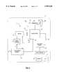
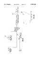
- FIG. 1is a schematic diagram of a hybrid powertrain system for a motor vehicle according to the present invention
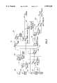
- FIG. 2is a data flow diagram showing the torque distribution control strategy for the hybrid powertrain system according to the principles of the present invention
- FIG. 3is a data flow diagram illustrating the calculation of the estimated motor torque available according to the principles of the present invention
- FIG. 4is a data flow diagram illustrating the calculation of the engine torque available according to the principles of the present invention.
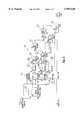
- FIG. 5is a data flow diagram illustrating the calculation of the motor torque available and the torque request for charging and discharging according to the principles of the present invention
- FIG. 6is a data flow diagram illustrating the calculation of an altered torque request according to the principles of the present invention.
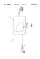
- FIG. 6ais a graphical representation of a sample look-up table used in the data flow diagram of FIG. 6;
- FIG. 7is a data flow diagram illustrating the calculation of an engine control command according to the principles of the present invention.
- FIG. 8is a data flow diagram illustrating the calculation of a motor control command according to the principles of the present invention.
- the hybrid powertrain system 10includes a heat engine 14 operating on a hydrocarbon based or fossil fuel.
- the engine 14is a compression-ignited engine fueled by a diesel fuel.
- the engine 14is sized comparable to an engine for a nonhybrid motor vehicle.
- the hybrid powertrain system 10also includes a clutch mechanism 16, as is known in the art, for operably interconnecting engine 14 and transmission 18.
- the Clutch mechanism 16compensates for the difference in rotational speed of engine 14 and transmission 18, to smooth engagement between engine 14 and transmission 18.
- Transmission 18connects to engine 14 through clutch 16 and transmits engine rotation and power at various ratios to a pair of drive wheels 26 of the motor vehicle.
- transmission 18enables the motor vehicle 8 to accelerate through predetermined gear ratios, while engine 14 functions within a predetermined operating range.
- Examples of known transmission typesinclude an automatic transmission, a manual transmission and a continuously variable transmission. It should be appreciated that in a preferred embodiment transmission 18 is a five-speed manual transmission as is well known in the art.
- Transmission 18drives a differential unit 28.
- Differential unit 28engages a pair of axle shafts 30 which are operably connected to the pair of wheels 26.
- the hybrid powertrain system 10also includes an electric motor 32 operably connected to transmission 18 at the opposite end of an input shaft from clutch 16.
- Electric motor 32is connected to the input shaft opposite from clutch 16 by a gear train 33.
- the electric motor 30is able to provide both positive and regenerative torque, by functioning as a motor and a generator, respectively.
- An example of an electric motor 32is an induction motor or a permanent magnet motor, such as manufactured by Delphi Electronics Corporation.
- electric motor 32produces a regenerative torque, preferably as an alternating current (A/C), which is transferred to a control mechanism, such as a motor controller 34.
- Motor controller 34changes the alternating current into a direct current (D/C), as is well known in the art.
- the direct currentmay then be transmitted to an energy storage apparatus 38, such as a battery.
- the electric motor 32produces a positive torque that is applied to the input shaft of the transmission 18 and is ultimately used to drive wheels 26.
- Motor vehicle 8is provided with a regenerative braking system, capable of capturing kinetic energy from the momentum of the motor vehicle as it is slowing down and storing this energy as potential energy in the energy storage apparatus 38 to be described.
- Electric motor 32slows the motor vehicle down by applying a braking force that slows down the rotation of the input shaft.
- Electric motor 32functions as a generator and captures the reverse energy flow.
- Hybrid powertrain system 10also includes a transmission controller 50, such as an electronic control unit.
- Transmission controller 50enables electronic control of transmission 18 to enable the transmission 18 to be configured as a manual-style transmission, but to be operated from a drivers standpoint as an automatic transmission.
- transmission 18has a pair of actuators 52 and 54 which simulate positioning of the stick shift actuators as in a conventional manual transmission.
- actuator 56enables operation of clutch 16 in replacement of a clutch pedal as on a conventional manual transmission.
- transmission controller 50receives input signals from engine 14 or an engine controller 58. Examples of such information received from engine 14 or engine controller 58 include vehicle speed, RPM, or the like.
- transmission controller 50generates output signals to control actuators 52, 54, and 56 and also outputs diagnostic and other communication signals to engine 14 and/or engine controller 58.
- Transmission controller 50may also receive other vehicle condition signals, depending on a particular configuration of the transmission 18.
- transmission controller 50receives input signals from engine 14, engine controller 58, clutch 16, clutch actuator 56, transmission 18, and from additional sensors.
- Actuator 56is preferably a rotary actuator which causes linear movement to effect engagement and disengagement of clutch 16.
- actuators 52 and 54these actuators combine to mimic movement of the shift lever in a conventional manual transmission. That is, in visioning the standard "H" shaped shift configuration, actuator 52 may operate as the cross over actuator, i.e., determining what leg of the "H" the shifter is in. Similarly, actuator 54 operates as a select actuator which mimics an upward or downward movement of the shifter within the leg of the H.
- the actuators 52, 54, and 56receive control signals from transmission controller 50 to operate the shifting portion of transmission 18 as in a conventional manual transmission. Further, transmission controller 50 sends control signals to electric motor 32 through motor controller 34, to effect activation and deactivation of electric motor 32 as determined by the control strategy described herein.
- Hybrid powertrain system 10includes an energy storage apparatus 38, such as battery, to store potential energy for later use by the motor vehicle.
- the potential energy stored in the batterymay be transferred, as DC current, to operate an accessory component 40.
- engine 14operably supplies a battery with potential energy.
- electric motor 32 operating as a generatorsupplies battery 38 with potential energy for storage.
- Hybrid powertrain system 10includes at least one accessory component 40.
- An example of an accessory componentmay be a power steering pump, a water pump, a lighting system, and a heating and cooling system, which are all conventional and well known in the art.
- Accessory components 40are usually mechanically driven by the engine 14 or electrically powered with energy from battery 38.
- accessory component 40such as the power steering pump, is operably connected to engine 14 and mechanically driven by engine 14.
- the lighting systemrelies on energy supplied by the battery 38, as a source of power.
- battery 38Upon command from the motor controller 34, battery 38 supplies potential energy, such as a D/C current, to motor controller 34, which converts it into an A/C current.
- the A/C currentis directed to the electric motor 32, causing it to act as a motor and produce a positive torque.
- the positive torqueis applied to the transmission 18, which in turn induces the rotation of the axle shaft 30 and the rotation of the drive wheels 26 of the motor vehicle.
- FIG. 1illustrates the data flow diagram for the torque distribution strategy of the present invention.
- the torque distribution strategyincludes first detecting a state of charge of a vehicle battery (SOC) at 100, detecting an accelerator position (APOS) at 102, detecting a gear number (GN) at 104, detecting an engine speed (S E ) at 108, and a motor speed (S M ) at 110.
- SOCvehicle battery
- APOSaccelerator position
- GNgear number
- S Eengine speed
- S Mmotor speed
- An estimated amount of motor torque available T MAEis detected at 112.
- the motor speed S M as converted by the gear ratio of the gear train 34(at 114) is input into a motor torque look-up table 116 and based upon the motor speed, an estimated motor torque available value T MAE is obtained.
- An amount of engine torque available T EAis determined at 120.
- the engine torque available T EAis determined based upon an engine speed S E which is input into a non-extrapolating torque table 122 to provide an engine torque T E .
- the derivative of the engine speed S E over time (du/dt)is calculated at 124.
- the engine speed S Eis input into first gear, second gear, and third gear engine speed rise limiters 126, 128, 130, respectively, which each provide a look-up table to provide a multiplier which varies with the engine speed S E .
- the multiplier obtained from first gear, second gear, and third gear rise limiters 126-130are then multiplied by the maximum engine torque available T E to provide a modified maximum engine torque available T EL1 , T EL2 , T EL3 at "Product” 132, "Product 1” 134, and “Product 2" 136, respectively.
- the "use 1st limit” 138, "use 2nd limit” 140, and "use 3rd limit” 142 boxeseach determine whether to use the maximum engine torque available values T EL1 , T EL2 , T EL3 , or the maximum engine torque available T E values, respectively.
- boxes labeled "first” 144, “second” 146, and “third” 148determine whether to use the calculated engine torque value based upon whether the transmission is in first gear, second gear, or third gear. If the transmission is in a gear higher than the third gear, the calculated maximum engine torque available T E is selected in box 148. In other words, blocks “first” 144, “second” 146, and “third” 148 determine which engine torque value to use based upon which gear number has been detected.
- a torque request for charging and discharging TRCD as well as an available motor torque T MAis determined at the box labeled "SOC and motor torque assist" 150.
- the battery state of charge SOC detected at 100is input into box 152 labeled "Thermostat Charge.”
- Box 152provides a boolean output of "0" or "1.” When the detected state of charge is below a predetermined level, then the output of box 152 is equal to 1 which indicates that the battery is low. This provides a charge rate command K (at 152) which will be described herein.
- the accelerator position APOSis multiplied by the estimated motor torque available T MAE which provides an amount of torque available for charging the battery. This value is then multiplied by the charge rate constant K at box 158.
- a boolean output of "0" or “1”is provided.
- the boolean output of "1”is provided when the detected state of charge is greater than a predetermined state of charge, generally indicating that the battery has a state of charge greater than a desired level. If the boolean operator is "1”, then an assist command K is provided at box 162. If the boolean operator is "0", no assist command is provided. At box 164, the assist command K is multiplied by the detected accelerator position APOS. At box 166, it is determined whether the detected state of charge SOC is greater than a minimum state of charge (minimum SOC). Box 166 also provides a boolean operator.
- a boolean operator equal to "1"is provided.
- a boolean operator equal to "0”is provided.
- the boolean operator from box 166is multiplied by the estimated motor torque available at box 168. Accordingly, the calculated value T MA in box 168 is either equal to the estimated motor torque available T MAE or equal to zero in the case that the detected state of charge SOC is not greater than the minimum state of charge (minimum SOC). Effectively, if the state of charge SOC is not greater than the minimum state of charge, the motor torque available T MA is equal to zero.
- the motor torque available T MAis multiplied by the product of the accelerator position APOS multiplied by the assist command K (obtained in box 164), in box 170.
- This value which represents a torque discharge request T RDis subtracted from the determined limited torque amount available for charging T RC at box 172 to provide a torque request for charging and discharging T RCD .
- the calculated engine torque available T EA and motor torque available T MAare added to provide a total torque available T TA .
- the calculated total torque available T TAis multiplied by the accelerator position APOS to provide a requested torque T R .
- the requested torque T Ris added to the calculated amount of requested torque for charging and discharging T RCD , to provide a total torque request T TR .
- the calculated total torque request T TRis limited at box 184 by a "limit rate of torque rise" characteristic curve, to provide a limited total torque request T LTR .
- the system of the present inventionlimits the rate of torque rise for the engine in order to minimize the engine emissions.
- the limits imposed on the rate of torque riseare reduced in order to provide the necessary torque response as required by the accelerator position APOS.
- the goal of reducing emissionsis at least partially reduced in value in order to meet the requirements of aggressive acceleration commands.
- the accelerator position APOSis provided to a look-up table which provides a variable output based upon the accelerator position. For example, as shown in FIG. 6a, when the accelerator position is less than a predetermined value, for example 0.8 (representative of 80 percent open throttle) the value provided by look-up table 186 is equal to zero. However, between the predetermined accelerator position (0.8 for example) and wide open throttle (1.0), a linear relationship is provided for providing a limiting multiplier l which is multiplied by the difference between the total torque requested T TR minus the limited total torque requested T LTR calculated in box 184.
- a predetermined valuefor example 0.8 (representative of 80 percent open throttle)
- a linear relationshipis provided for providing a limiting multiplier l which is multiplied by the difference between the total torque requested T TR minus the limited total torque requested T LTR calculated in box 184.
- the product of this valueis then added to the limited total torque requested T LTR in box 190 to provide an altered torque request T AR .
- the multiplier lis equal to zero. Therefore, the altered torque T AR is equal to the limited total torque request T LTR .
- the predetermined positionfor example 0.8
- the altered torque request T ARis equal to the limited total torque request T LTR plus the product of the total torque request T TR minus the limited total torque request T LTR times the multiplier l.
- the multiplier lapproaches 1
- the altered torque request A TRapproaches the total torque request T TR . Therefore, the effect of limiting the engine torque rise is at least partially negated after the accelerator position exceeds the predetermined value.
- the example Look-Up Table as illustrated in figure 62could be altered in many ways. For example, a non-linear or step increase in the value l may be utilized.
- the system of the present inventioncould, upon the accelerator position reaching a predetermined value, ignore the limited total torque request T LTR and simply use the total torque request T TR as the altered torque T AR value. In effect, this would be the equivalent of using a step increase for l to go from "0" to "1" when accelerator position exceeded a predetermined value.
- a normal engine commandis determined.
- the engine command ECis equal to the ratio of the altered torque request T AR divided by the maximum engine torque available T EA as calculated in box 194 of FIG. 7.
- the engine command ECis then multiplied by the engine torque available T EA in box 196 to provide an engine torque request T ER .
- the engine torque request T ERis then subtracted from the requested torque T R in box 198 to provide a motor torque request T MR in box 200, a motor command MC is determined as shown in FIG. 8.
- the motor command MCis equal to the ratio of the motor torque request T MR divided by the estimated motor torque available T MAE as calculated in box 202.
- the engine and motor commands EC and MCare determined based upon a strategy to reduce emissions and provide the desired amount of driving torque.
Landscapes
- Engineering & Computer Science (AREA)
- Transportation (AREA)
- Mechanical Engineering (AREA)
- Chemical & Material Sciences (AREA)
- Combustion & Propulsion (AREA)
- Power Engineering (AREA)
- Automation & Control Theory (AREA)
- Electric Propulsion And Braking For Vehicles (AREA)
- Hybrid Electric Vehicles (AREA)
Abstract
Description
Claims (8)
Priority Applications (1)
| Application Number | Priority Date | Filing Date | Title |
|---|---|---|---|
| US08/982,047US5959420A (en) | 1997-12-01 | 1997-12-01 | Heat engine and electric motor torque distribution strategy for a hybrid electric vehicle |
Applications Claiming Priority (1)
| Application Number | Priority Date | Filing Date | Title |
|---|---|---|---|
| US08/982,047US5959420A (en) | 1997-12-01 | 1997-12-01 | Heat engine and electric motor torque distribution strategy for a hybrid electric vehicle |
Publications (1)
| Publication Number | Publication Date |
|---|---|
| US5959420Atrue US5959420A (en) | 1999-09-28 |
Family
ID=25528804
Family Applications (1)
| Application Number | Title | Priority Date | Filing Date |
|---|---|---|---|
| US08/982,047Expired - LifetimeUS5959420A (en) | 1997-12-01 | 1997-12-01 | Heat engine and electric motor torque distribution strategy for a hybrid electric vehicle |
Country Status (1)
| Country | Link |
|---|---|
| US (1) | US5959420A (en) |
Cited By (39)
| Publication number | Priority date | Publication date | Assignee | Title |
|---|---|---|---|---|
| US6090007A (en)* | 1998-03-20 | 2000-07-18 | Nissan Motor Co., Ltd. | Hybrid vehicle drive force control device and control method |
| FR2799163A1 (en)* | 1999-10-01 | 2001-04-06 | Renault | Control system for hybrid vehicle, comprises calculator which calculates the torque values of first and second electric motors as functions of three final quantities, the acceleration, the thermal motor torque and the torque at the wheels |
| US6253866B1 (en)* | 1997-12-09 | 2001-07-03 | Toyota Jidosha Kabushiki Kaisha | Internal combustion engine control apparatus of hybrid powered vehicle |
| FR2808050A1 (en)* | 2000-04-21 | 2001-10-26 | Toyota Motor Co Ltd | INTERNAL COMBUSTION ENGINE CONTROL UNIT FOR A HYBRID VEHICLE AND METHOD FOR CONTROLLING A HYBRID VEHICLE |
| US6328671B1 (en) | 1998-03-20 | 2001-12-11 | Nissan Motor Co., Ltd. | Drive force control device |
| US6441574B1 (en)* | 2000-10-27 | 2002-08-27 | Ford Motor Company | Energy control strategy for a hybrid electric vehicle |
| US6453222B1 (en)* | 2000-10-31 | 2002-09-17 | Volvo Car Corporation | Method and arrangement in a hybrid vehicle for matching engine and generator torques at times of engagement and disengagement |
| US6455947B1 (en) | 2001-02-14 | 2002-09-24 | Bae Systems Controls, Inc. | Power combining apparatus for hybrid electric vehicle |
| US20030085577A1 (en)* | 1999-11-19 | 2003-05-08 | Toyota Jidosha Kabushiki Kaisha | Control apparatus for transmission-equipped hybrid vehicle, and control method for the same |
| US20040045751A1 (en)* | 2001-03-08 | 2004-03-11 | Kazuo Aoki | Hybrid vehicle drive control apparatus, and control method of hybrid vehicle drive apparatus and program thereof |
| US20040069547A1 (en)* | 2001-09-29 | 2004-04-15 | Dieter Hoetzer | Electric motor coupled to an internal combustion engine in a motor vehicle |
| US6739994B1 (en)* | 1998-08-27 | 2004-05-25 | Gear Chain Industrial, Bv | Control system for a continuously variable v-belt transmission |
| US6825575B1 (en)* | 1999-09-28 | 2004-11-30 | Borealis Technical Limited | Electronically controlled engine generator set |
| US20050103544A1 (en)* | 2003-09-24 | 2005-05-19 | Aisin Aw Co., Ltd. | Control apparatus of hybrid vehicle |
| US20070262749A1 (en)* | 2006-05-11 | 2007-11-15 | Yunfei Luan | Method and apparatus for controlling vehicle battery charging |
| US20080238108A1 (en)* | 1999-09-28 | 2008-10-02 | Jonathan Sidney Edelson | Electronically Controlled Engine Generator Set |
| CN100429433C (en)* | 2004-08-05 | 2008-10-29 | 本田技研工业株式会社 | Shift controller for a continuously variable transmission |
| US20080319619A1 (en)* | 2007-06-21 | 2008-12-25 | Honda Motor Co., Ltd. | Vehicle drive control system |
| WO2009078835A1 (en)* | 2007-12-17 | 2009-06-25 | Net Gain Technologies, Llc | Motor vehicle with electric boost motor |
| WO2010066582A1 (en)* | 2008-12-10 | 2010-06-17 | Robert Bosch Gmbh | Method and device for operating a drive train for a vehicle |
| US20100301867A1 (en)* | 2009-05-29 | 2010-12-02 | Gm Global Technology Operations, Inc. | Regeneration capacity control method for a battery |
| US20110184602A1 (en)* | 1998-09-14 | 2011-07-28 | Paice Llc | Hybrid vehicles |
| US20120204539A1 (en)* | 2011-02-10 | 2012-08-16 | GM Global Technology Operations LLC | Hybrid vehicle thermal management using a bypass path in a catalytic converter unit |
| JP2014097766A (en)* | 2012-11-15 | 2014-05-29 | Shin Meiwa Ind Co Ltd | Hybrid electric work vehicle |
| US20160368478A1 (en)* | 2015-06-19 | 2016-12-22 | Hyundai Motor Company | Apparatus and method for controlling torque reduction of hybrid electric vehicle |
| CN106394549A (en)* | 2016-08-31 | 2017-02-15 | 北京新能源汽车股份有限公司 | Torque distribution method and device for hybrid electric vehicle |
| US20170066430A1 (en)* | 2015-09-04 | 2017-03-09 | Hyundai Motor Company | Apparatus and method for controlling torque reduction of hybrid electric vehicle |
| US10882399B2 (en) | 2005-11-17 | 2021-01-05 | Invently Automotive Inc. | Electric vehicle power management system |
| US11180025B2 (en) | 2005-11-17 | 2021-11-23 | Invently Automotive Inc. | Electric vehicle power management system |
| US11186173B2 (en) | 2005-11-17 | 2021-11-30 | Invently Automotive Inc. | Electric vehicle power management system |
| US11214144B2 (en) | 2005-11-17 | 2022-01-04 | Invently Automotive Inc. | Electric vehicle power management system |
| US11230190B2 (en) | 2005-11-17 | 2022-01-25 | Invently Automotive Inc. | Electric vehicle power management system |
| US11247564B2 (en) | 2005-11-17 | 2022-02-15 | Invently Automotive Inc. | Electric vehicle power management system |
| US11254211B2 (en) | 2005-11-17 | 2022-02-22 | Invently Automotive Inc. | Electric vehicle power management system |
| US11267338B2 (en) | 2005-11-17 | 2022-03-08 | Invently Automotive Inc. | Electric vehicle power management system |
| US11279233B2 (en) | 2005-11-17 | 2022-03-22 | Invently Automotive Inc. | Electric vehicle power management system |
| US11345236B2 (en) | 2005-11-17 | 2022-05-31 | Invently Automotive Inc. | Electric vehicle power management system |
| US11370302B2 (en) | 2005-11-17 | 2022-06-28 | Invently Automotive Inc. | Electric vehicle power management system |
| US11390165B2 (en) | 2005-11-17 | 2022-07-19 | Invently Automotive Inc. | Electric vehicle power management system |
Citations (6)
| Publication number | Priority date | Publication date | Assignee | Title |
|---|---|---|---|---|
| US3916862A (en)* | 1973-10-26 | 1975-11-04 | Caterpillar Tractor Co | Torque rise limiting device |
| US4149507A (en)* | 1977-10-27 | 1979-04-17 | Caterpillar Tractor Co. | Fuel-air ratio control with torque-limiting spring for supercharged engines |
| US5376869A (en)* | 1993-02-11 | 1994-12-27 | General Electric Company | Electric vehicle drive train with rollback detection and compensation |
| US5578911A (en)* | 1994-09-21 | 1996-11-26 | Chrysler Corporation | Method and apparatus for power regeneration in an electric vehicle motor drive using a deadtime generator and having continuously variable regeneration control |
| US5680917A (en)* | 1995-09-27 | 1997-10-28 | Caterpillar Inc. | Clutch or brake engagement pressure compensation |
| US5695430A (en)* | 1994-09-21 | 1997-12-09 | Moyer; David F. | Hybrid internal combustion engine |
- 1997
- 1997-12-01USUS08/982,047patent/US5959420A/ennot_activeExpired - Lifetime
Patent Citations (6)
| Publication number | Priority date | Publication date | Assignee | Title |
|---|---|---|---|---|
| US3916862A (en)* | 1973-10-26 | 1975-11-04 | Caterpillar Tractor Co | Torque rise limiting device |
| US4149507A (en)* | 1977-10-27 | 1979-04-17 | Caterpillar Tractor Co. | Fuel-air ratio control with torque-limiting spring for supercharged engines |
| US5376869A (en)* | 1993-02-11 | 1994-12-27 | General Electric Company | Electric vehicle drive train with rollback detection and compensation |
| US5578911A (en)* | 1994-09-21 | 1996-11-26 | Chrysler Corporation | Method and apparatus for power regeneration in an electric vehicle motor drive using a deadtime generator and having continuously variable regeneration control |
| US5695430A (en)* | 1994-09-21 | 1997-12-09 | Moyer; David F. | Hybrid internal combustion engine |
| US5680917A (en)* | 1995-09-27 | 1997-10-28 | Caterpillar Inc. | Clutch or brake engagement pressure compensation |
Cited By (67)
| Publication number | Priority date | Publication date | Assignee | Title |
|---|---|---|---|---|
| US6253866B1 (en)* | 1997-12-09 | 2001-07-03 | Toyota Jidosha Kabushiki Kaisha | Internal combustion engine control apparatus of hybrid powered vehicle |
| US6328671B1 (en) | 1998-03-20 | 2001-12-11 | Nissan Motor Co., Ltd. | Drive force control device |
| US6090007A (en)* | 1998-03-20 | 2000-07-18 | Nissan Motor Co., Ltd. | Hybrid vehicle drive force control device and control method |
| US6739994B1 (en)* | 1998-08-27 | 2004-05-25 | Gear Chain Industrial, Bv | Control system for a continuously variable v-belt transmission |
| US9463698B2 (en) | 1998-09-14 | 2016-10-11 | Paice Llc | Hybrid vehicles |
| US9050972B2 (en) | 1998-09-14 | 2015-06-09 | Paice Llc | Hybrid vehicles |
| US20110184602A1 (en)* | 1998-09-14 | 2011-07-28 | Paice Llc | Hybrid vehicles |
| US9573585B2 (en) | 1998-09-14 | 2017-02-21 | Paice Llc | Hybrid vehicles |
| US7105938B2 (en) | 1999-09-28 | 2006-09-12 | Borealis Technical Limited | Electronically controlled engine generator set |
| US20050116474A1 (en)* | 1999-09-28 | 2005-06-02 | Edelson Jonathan S. | Electronically controlled engine generator set |
| US7905813B2 (en) | 1999-09-28 | 2011-03-15 | Borealis Technical Limited | Electronically controlled engine generator set |
| US6825575B1 (en)* | 1999-09-28 | 2004-11-30 | Borealis Technical Limited | Electronically controlled engine generator set |
| US20080238108A1 (en)* | 1999-09-28 | 2008-10-02 | Jonathan Sidney Edelson | Electronically Controlled Engine Generator Set |
| WO2001025049A1 (en)* | 1999-10-01 | 2001-04-12 | Renault | Control method for hybrid vehicle |
| FR2799163A1 (en)* | 1999-10-01 | 2001-04-06 | Renault | Control system for hybrid vehicle, comprises calculator which calculates the torque values of first and second electric motors as functions of three final quantities, the acceleration, the thermal motor torque and the torque at the wheels |
| US20030085577A1 (en)* | 1999-11-19 | 2003-05-08 | Toyota Jidosha Kabushiki Kaisha | Control apparatus for transmission-equipped hybrid vehicle, and control method for the same |
| US6781251B2 (en)* | 1999-11-19 | 2004-08-24 | Toyota Jidosha Kabushiki Kaisha | Control apparatus for transmission-equipped hybrid vehicle, and control method for the same |
| US6867509B1 (en)* | 1999-11-19 | 2005-03-15 | Toyota Jidosha Kabushiki Kaisha | Control apparatus for transmission-equipped hybrid vehicle, and control method for the same |
| US6520160B2 (en) | 2000-04-21 | 2003-02-18 | Toyota Jidosha Kabushiki Kaisha | Internal combustion engine control unit for, and method of controlling a hybrid vehicle |
| FR2808050A1 (en)* | 2000-04-21 | 2001-10-26 | Toyota Motor Co Ltd | INTERNAL COMBUSTION ENGINE CONTROL UNIT FOR A HYBRID VEHICLE AND METHOD FOR CONTROLLING A HYBRID VEHICLE |
| EP1201486A3 (en)* | 2000-10-27 | 2003-11-05 | Ford Motor Company | Energy control strategy for a hybrid electric vehicle |
| US6441574B1 (en)* | 2000-10-27 | 2002-08-27 | Ford Motor Company | Energy control strategy for a hybrid electric vehicle |
| US6453222B1 (en)* | 2000-10-31 | 2002-09-17 | Volvo Car Corporation | Method and arrangement in a hybrid vehicle for matching engine and generator torques at times of engagement and disengagement |
| KR100803533B1 (en)* | 2001-02-14 | 2008-02-15 | 배 시스템즈 컨트롤즈 인코포레이티드 | Power combiner for hybrid electric vehicle |
| US6455947B1 (en) | 2001-02-14 | 2002-09-24 | Bae Systems Controls, Inc. | Power combining apparatus for hybrid electric vehicle |
| USRE41034E1 (en) | 2001-02-14 | 2009-12-15 | Bae Systems Controls Inc. | Power combining apparatus for hybrid electric vehicle |
| US7117071B2 (en)* | 2001-03-08 | 2006-10-03 | Aisin Aw Co., Ltd. | Hybrid vehicle drive control apparatus, and control method of hybrid vehicle drive apparatus and program thereof |
| US20040045751A1 (en)* | 2001-03-08 | 2004-03-11 | Kazuo Aoki | Hybrid vehicle drive control apparatus, and control method of hybrid vehicle drive apparatus and program thereof |
| US7198589B2 (en)* | 2001-09-29 | 2007-04-03 | Robert Bosch Gmbh | Electric motor coupled to an internal combustion engine in a motor vehicle |
| US20040069547A1 (en)* | 2001-09-29 | 2004-04-15 | Dieter Hoetzer | Electric motor coupled to an internal combustion engine in a motor vehicle |
| US7434641B2 (en)* | 2003-09-24 | 2008-10-14 | Aisin Aw Co., Ltd. | Control apparatus of hybrid vehicle |
| US20050103544A1 (en)* | 2003-09-24 | 2005-05-19 | Aisin Aw Co., Ltd. | Control apparatus of hybrid vehicle |
| CN100429433C (en)* | 2004-08-05 | 2008-10-29 | 本田技研工业株式会社 | Shift controller for a continuously variable transmission |
| US10882399B2 (en) | 2005-11-17 | 2021-01-05 | Invently Automotive Inc. | Electric vehicle power management system |
| US11279233B2 (en) | 2005-11-17 | 2022-03-22 | Invently Automotive Inc. | Electric vehicle power management system |
| US11370302B2 (en) | 2005-11-17 | 2022-06-28 | Invently Automotive Inc. | Electric vehicle power management system |
| US11180025B2 (en) | 2005-11-17 | 2021-11-23 | Invently Automotive Inc. | Electric vehicle power management system |
| US11390165B2 (en) | 2005-11-17 | 2022-07-19 | Invently Automotive Inc. | Electric vehicle power management system |
| US11345236B2 (en) | 2005-11-17 | 2022-05-31 | Invently Automotive Inc. | Electric vehicle power management system |
| US11186173B2 (en) | 2005-11-17 | 2021-11-30 | Invently Automotive Inc. | Electric vehicle power management system |
| US11214144B2 (en) | 2005-11-17 | 2022-01-04 | Invently Automotive Inc. | Electric vehicle power management system |
| US11267338B2 (en) | 2005-11-17 | 2022-03-08 | Invently Automotive Inc. | Electric vehicle power management system |
| US11230190B2 (en) | 2005-11-17 | 2022-01-25 | Invently Automotive Inc. | Electric vehicle power management system |
| US11254211B2 (en) | 2005-11-17 | 2022-02-22 | Invently Automotive Inc. | Electric vehicle power management system |
| US11247564B2 (en) | 2005-11-17 | 2022-02-15 | Invently Automotive Inc. | Electric vehicle power management system |
| US7834582B2 (en)* | 2006-05-11 | 2010-11-16 | Gm Global Technology Operations, Inc. | Method and apparatus for controlling vehicle battery charging |
| US20070262749A1 (en)* | 2006-05-11 | 2007-11-15 | Yunfei Luan | Method and apparatus for controlling vehicle battery charging |
| US8255104B2 (en) | 2007-06-21 | 2012-08-28 | Honda Motor Co., Ltd. | Vehicle drive control system |
| EP2014531A3 (en)* | 2007-06-21 | 2009-06-03 | Honda Motor Co., Ltd | Vehicle drive control system |
| CN101327793B (en)* | 2007-06-21 | 2012-05-16 | 本田技研工业株式会社 | Drive control device for vehicle |
| EP2014531A2 (en) | 2007-06-21 | 2009-01-14 | Honda Motor Co., Ltd | Vehicle drive control system |
| US20080319619A1 (en)* | 2007-06-21 | 2008-12-25 | Honda Motor Co., Ltd. | Vehicle drive control system |
| WO2009078835A1 (en)* | 2007-12-17 | 2009-06-25 | Net Gain Technologies, Llc | Motor vehicle with electric boost motor |
| CN102245454B (en)* | 2008-12-10 | 2014-11-12 | 罗伯特·博世有限公司 | Method and apparatus for operating a drive train of a vehicle |
| WO2010066582A1 (en)* | 2008-12-10 | 2010-06-17 | Robert Bosch Gmbh | Method and device for operating a drive train for a vehicle |
| CN102245454A (en)* | 2008-12-10 | 2011-11-16 | 罗伯特·博世有限公司 | Method and apparatus for operating a drive train of a vehicle |
| US8751080B2 (en) | 2008-12-10 | 2014-06-10 | Robert Bosch Gmbh | Method and device for operating a drive train for a vehicle |
| US20100301867A1 (en)* | 2009-05-29 | 2010-12-02 | Gm Global Technology Operations, Inc. | Regeneration capacity control method for a battery |
| US8228035B2 (en)* | 2009-05-29 | 2012-07-24 | GM Global Technology Operations LLC | Regeneration capacity control method for a battery |
| US20120204539A1 (en)* | 2011-02-10 | 2012-08-16 | GM Global Technology Operations LLC | Hybrid vehicle thermal management using a bypass path in a catalytic converter unit |
| JP2014097766A (en)* | 2012-11-15 | 2014-05-29 | Shin Meiwa Ind Co Ltd | Hybrid electric work vehicle |
| US20160368478A1 (en)* | 2015-06-19 | 2016-12-22 | Hyundai Motor Company | Apparatus and method for controlling torque reduction of hybrid electric vehicle |
| US9656661B2 (en)* | 2015-06-19 | 2017-05-23 | Hyundai Motor Company | Apparatus and method for controlling torque reduction of hybrid electric vehicle |
| US20170066430A1 (en)* | 2015-09-04 | 2017-03-09 | Hyundai Motor Company | Apparatus and method for controlling torque reduction of hybrid electric vehicle |
| US9610937B2 (en)* | 2015-09-04 | 2017-04-04 | Hyundai Motor Company | Apparatus and method for controlling torque reduction of hybrid electric vehicle |
| CN106394549A (en)* | 2016-08-31 | 2017-02-15 | 北京新能源汽车股份有限公司 | Torque distribution method and device for hybrid electric vehicle |
| CN106394549B (en)* | 2016-08-31 | 2019-01-29 | 北京新能源汽车股份有限公司 | torque distribution method and device for hybrid electric vehicle |
Similar Documents
| Publication | Publication Date | Title |
|---|---|---|
| US5959420A (en) | Heat engine and electric motor torque distribution strategy for a hybrid electric vehicle | |
| US6155365A (en) | Brake blending strategy for a hybrid vehicle | |
| US7178617B2 (en) | Hybrid vehicle | |
| US6186255B1 (en) | Hybrid vehicle | |
| US6183389B1 (en) | Control system for lock-up clutch | |
| US6540035B2 (en) | Hybrid vehicle | |
| US5376869A (en) | Electric vehicle drive train with rollback detection and compensation | |
| US6317665B1 (en) | Vehicle control system | |
| US8903581B2 (en) | Method and apparatus for starting an engine in a hybrid vehicle | |
| US5993351A (en) | Control device for hybrid vehicle | |
| JP3514142B2 (en) | Vehicle control device | |
| EP1354746B1 (en) | Hybrid vehicle system | |
| US20070205735A1 (en) | Control device for a hybrid electric vehicle | |
| US20170327102A1 (en) | Driveline lash control method during driver tip-in/out | |
| CN104787033A (en) | Method for controlling regenerative braking | |
| US8798836B2 (en) | Control device for hybrid vehicle | |
| US9605605B2 (en) | Vehicle control apparatus | |
| US10746291B2 (en) | Engine torque and torque converter bypass clutch slip control during vehicle launch | |
| JP3454172B2 (en) | Hybrid vehicle control method | |
| US20040261557A1 (en) | Gear box for motor vehicles | |
| US20120065822A1 (en) | Speed control method and speed control device for automatic transmission | |
| US10988133B2 (en) | Vehicle exhaust sound control systems and methods | |
| JP2000001133A (en) | Hybrid vehicle control device | |
| US11981210B2 (en) | Controller and control method for hybrid vehicle | |
| JP3763223B2 (en) | Control device for hybrid vehicle |
Legal Events
| Date | Code | Title | Description |
|---|---|---|---|
| AS | Assignment | Owner name:CHRYSLER CORPORATION, MICHIGAN Free format text:ASSIGNMENT OF ASSIGNORS INTEREST;ASSIGNORS:BOBERG, EVAN S.;GEBBY, BRIAN P.;REEL/FRAME:008874/0498 Effective date:19971201 | |
| AS | Assignment | Owner name:ENERGY, UNITED STATES DEPARTMENT OF, DISTRICT OF C Free format text:CONFIRMATORY LICENSE;ASSIGNOR:CHRYSLER CORPORATION;REEL/FRAME:009650/0277 Effective date:19981024 | |
| STCF | Information on status: patent grant | Free format text:PATENTED CASE | |
| FPAY | Fee payment | Year of fee payment:4 | |
| FPAY | Fee payment | Year of fee payment:8 | |
| AS | Assignment | Owner name:WILMINGTON TRUST COMPANY, DELAWARE Free format text:GRANT OF SECURITY INTEREST IN PATENT RIGHTS - FIRST PRIORITY;ASSIGNOR:CHRYSLER LLC;REEL/FRAME:019773/0001 Effective date:20070803 Owner name:WILMINGTON TRUST COMPANY,DELAWARE Free format text:GRANT OF SECURITY INTEREST IN PATENT RIGHTS - FIRST PRIORITY;ASSIGNOR:CHRYSLER LLC;REEL/FRAME:019773/0001 Effective date:20070803 | |
| AS | Assignment | Owner name:WILMINGTON TRUST COMPANY, DELAWARE Free format text:GRANT OF SECURITY INTEREST IN PATENT RIGHTS - SECOND PRIORITY;ASSIGNOR:CHRYSLER LLC;REEL/FRAME:019767/0810 Effective date:20070803 Owner name:WILMINGTON TRUST COMPANY,DELAWARE Free format text:GRANT OF SECURITY INTEREST IN PATENT RIGHTS - SECOND PRIORITY;ASSIGNOR:CHRYSLER LLC;REEL/FRAME:019767/0810 Effective date:20070803 | |
| AS | Assignment | Owner name:US DEPARTMENT OF THE TREASURY, DISTRICT OF COLUMBI Free format text:GRANT OF SECURITY INTEREST IN PATENT RIGHTS - THIR;ASSIGNOR:CHRYSLER LLC;REEL/FRAME:022259/0188 Effective date:20090102 Owner name:US DEPARTMENT OF THE TREASURY,DISTRICT OF COLUMBIA Free format text:GRANT OF SECURITY INTEREST IN PATENT RIGHTS - THIR;ASSIGNOR:CHRYSLER LLC;REEL/FRAME:022259/0188 Effective date:20090102 | |
| AS | Assignment | Owner name:CHRYSLER LLC, MICHIGAN Free format text:RELEASE BY SECURED PARTY;ASSIGNOR:US DEPARTMENT OF THE TREASURY;REEL/FRAME:022910/0273 Effective date:20090608 | |
| AS | Assignment | Owner name:CHRYSLER LLC, MICHIGAN Free format text:RELEASE OF SECURITY INTEREST IN PATENT RIGHTS - FIRST PRIORITY;ASSIGNOR:WILMINGTON TRUST COMPANY;REEL/FRAME:022910/0498 Effective date:20090604 Owner name:CHRYSLER LLC, MICHIGAN Free format text:RELEASE OF SECURITY INTEREST IN PATENT RIGHTS - SECOND PRIORITY;ASSIGNOR:WILMINGTON TRUST COMPANY;REEL/FRAME:022910/0740 Effective date:20090604 Owner name:NEW CARCO ACQUISITION LLC, MICHIGAN Free format text:ASSIGNMENT OF ASSIGNORS INTEREST;ASSIGNOR:CHRYSLER LLC;REEL/FRAME:022915/0001 Effective date:20090610 Owner name:THE UNITED STATES DEPARTMENT OF THE TREASURY, DIST Free format text:SECURITY AGREEMENT;ASSIGNOR:NEW CARCO ACQUISITION LLC;REEL/FRAME:022915/0489 Effective date:20090610 Owner name:CHRYSLER LLC,MICHIGAN Free format text:RELEASE OF SECURITY INTEREST IN PATENT RIGHTS - FIRST PRIORITY;ASSIGNOR:WILMINGTON TRUST COMPANY;REEL/FRAME:022910/0498 Effective date:20090604 Owner name:CHRYSLER LLC,MICHIGAN Free format text:RELEASE OF SECURITY INTEREST IN PATENT RIGHTS - SECOND PRIORITY;ASSIGNOR:WILMINGTON TRUST COMPANY;REEL/FRAME:022910/0740 Effective date:20090604 Owner name:NEW CARCO ACQUISITION LLC,MICHIGAN Free format text:ASSIGNMENT OF ASSIGNORS INTEREST;ASSIGNOR:CHRYSLER LLC;REEL/FRAME:022915/0001 Effective date:20090610 Owner name:THE UNITED STATES DEPARTMENT OF THE TREASURY,DISTR Free format text:SECURITY AGREEMENT;ASSIGNOR:NEW CARCO ACQUISITION LLC;REEL/FRAME:022915/0489 Effective date:20090610 | |
| AS | Assignment | Owner name:CHRYSLER GROUP LLC, MICHIGAN Free format text:CHANGE OF NAME;ASSIGNOR:NEW CARCO ACQUISITION LLC;REEL/FRAME:022919/0126 Effective date:20090610 Owner name:CHRYSLER GROUP LLC,MICHIGAN Free format text:CHANGE OF NAME;ASSIGNOR:NEW CARCO ACQUISITION LLC;REEL/FRAME:022919/0126 Effective date:20090610 | |
| FPAY | Fee payment | Year of fee payment:12 | |
| AS | Assignment | Owner name:CHRYSLER GROUP GLOBAL ELECTRIC MOTORCARS LLC, NORT Free format text:RELEASE BY SECURED PARTY;ASSIGNOR:THE UNITED STATES DEPARTMENT OF THE TREASURY;REEL/FRAME:026343/0298 Effective date:20110524 Owner name:CHRYSLER GROUP LLC, MICHIGAN Free format text:RELEASE BY SECURED PARTY;ASSIGNOR:THE UNITED STATES DEPARTMENT OF THE TREASURY;REEL/FRAME:026343/0298 Effective date:20110524 | |
| AS | Assignment | Owner name:CITIBANK, N.A., NEW YORK Free format text:SECURITY AGREEMENT;ASSIGNOR:CHRYSLER GROUP LLC;REEL/FRAME:026404/0123 Effective date:20110524 | |
| AS | Assignment | Owner name:CITIBANK, N.A., NEW YORK Free format text:SECURITY AGREEMENT;ASSIGNOR:CHRYSLER GROUP LLC;REEL/FRAME:026435/0652 Effective date:20110524 | |
| AS | Assignment | Owner name:JPMORGAN CHASE BANK, N.A., ILLINOIS Free format text:SECURITY AGREEMENT;ASSIGNOR:CHRYSLER GROUP LLC;REEL/FRAME:032384/0640 Effective date:20140207 | |
| AS | Assignment | Owner name:FCA US LLC, MICHIGAN Free format text:CHANGE OF NAME;ASSIGNOR:CHRYSLER GROUP LLC;REEL/FRAME:035553/0356 Effective date:20141203 | |
| AS | Assignment | Owner name:FCA US LLC, FORMERLY KNOWN AS CHRYSLER GROUP LLC, Free format text:RELEASE OF SECURITY INTEREST RELEASING SECOND-LIEN SECURITY INTEREST PREVIOUSLY RECORDED AT REEL 026426 AND FRAME 0644, REEL 026435 AND FRAME 0652, AND REEL 032384 AND FRAME 0591;ASSIGNOR:CITIBANK, N.A.;REEL/FRAME:037784/0001 Effective date:20151221 | |
| AS | Assignment | Owner name:FCA US LLC (FORMERLY KNOWN AS CHRYSLER GROUP LLC), Free format text:RELEASE BY SECURED PARTY;ASSIGNOR:CITIBANK, N.A.;REEL/FRAME:042885/0255 Effective date:20170224 | |
| AS | Assignment | Owner name:FCA US LLC (FORMERLY KNOWN AS CHRYSLER GROUP LLC), Free format text:RELEASE BY SECURED PARTY;ASSIGNOR:JPMORGAN CHASE BANK, N.A.;REEL/FRAME:048177/0356 Effective date:20181113 |