US5959382A - Magnetic actuator and position control system - Google Patents
Magnetic actuator and position control systemDownload PDFInfo
- Publication number
- US5959382A US5959382AUS08/730,712US73071296AUS5959382AUS 5959382 AUS5959382 AUS 5959382AUS 73071296 AUS73071296 AUS 73071296AUS 5959382 AUS5959382 AUS 5959382A
- Authority
- US
- United States
- Prior art keywords
- stator
- rotor
- slots
- actuator
- sector
- Prior art date
- Legal status (The legal status is an assumption and is not a legal conclusion. Google has not performed a legal analysis and makes no representation as to the accuracy of the status listed.)
- Expired - Fee Related
Links
- 239000004020conductorSubstances0.000claimsabstractdescription47
- XEEYBQQBJWHFJM-UHFFFAOYSA-NIronChemical compound[Fe]XEEYBQQBJWHFJM-UHFFFAOYSA-N0.000claimsabstractdescription32
- 230000004907fluxEffects0.000claimsabstractdescription17
- 229910052742ironInorganic materials0.000claimsabstractdescription16
- 238000004519manufacturing processMethods0.000description6
- 230000008901benefitEffects0.000description5
- 238000010586diagramMethods0.000description5
- 238000005516engineering processMethods0.000description5
- 230000003247decreasing effectEffects0.000description4
- 238000000034methodMethods0.000description4
- 239000000725suspensionSubstances0.000description4
- 230000005284excitationEffects0.000description3
- 239000000463materialSubstances0.000description3
- 238000009987spinningMethods0.000description3
- 230000001133accelerationEffects0.000description2
- 239000003990capacitorSubstances0.000description2
- 238000013500data storageMethods0.000description2
- 239000000696magnetic materialSubstances0.000description2
- 238000005459micromachiningMethods0.000description2
- 230000035945sensitivityEffects0.000description2
- 238000010276constructionMethods0.000description1
- 238000000151depositionMethods0.000description1
- 230000008021depositionEffects0.000description1
- 230000000694effectsEffects0.000description1
- 238000004070electrodepositionMethods0.000description1
- 238000005530etchingMethods0.000description1
- 238000009413insulationMethods0.000description1
- 230000010354integrationEffects0.000description1
- 230000003993interactionEffects0.000description1
- VIKNJXKGJWUCNN-XGXHKTLJSA-NnorethisteroneChemical compoundO=C1CC[C@@H]2[C@H]3CC[C@](C)([C@](CC4)(O)C#C)[C@@H]4[C@@H]3CCC2=C1VIKNJXKGJWUCNN-XGXHKTLJSA-N0.000description1
- 230000002028prematureEffects0.000description1
- 230000002441reversible effectEffects0.000description1
- 239000007787solidSubstances0.000description1
- 238000003860storageMethods0.000description1
- 239000010409thin filmSubstances0.000description1
Images


Classifications
- F—MECHANICAL ENGINEERING; LIGHTING; HEATING; WEAPONS; BLASTING
- F16—ENGINEERING ELEMENTS AND UNITS; GENERAL MEASURES FOR PRODUCING AND MAINTAINING EFFECTIVE FUNCTIONING OF MACHINES OR INSTALLATIONS; THERMAL INSULATION IN GENERAL
- F16C—SHAFTS; FLEXIBLE SHAFTS; ELEMENTS OR CRANKSHAFT MECHANISMS; ROTARY BODIES OTHER THAN GEARING ELEMENTS; BEARINGS
- F16C32/00—Bearings not otherwise provided for
- F16C32/04—Bearings not otherwise provided for using magnetic or electric supporting means
- F16C32/0406—Magnetic bearings
- F16C32/044—Active magnetic bearings
- F16C32/0474—Active magnetic bearings for rotary movement
- F16C32/0493—Active magnetic bearings for rotary movement integrated in an electrodynamic machine, e.g. self-bearing motor
- H—ELECTRICITY
- H02—GENERATION; CONVERSION OR DISTRIBUTION OF ELECTRIC POWER
- H02K—DYNAMO-ELECTRIC MACHINES
- H02K19/00—Synchronous motors or generators
- H02K19/02—Synchronous motors
- H02K19/10—Synchronous motors for multi-phase current
- H02K19/103—Motors having windings on the stator and a variable reluctance soft-iron rotor without windings
- H—ELECTRICITY
- H02—GENERATION; CONVERSION OR DISTRIBUTION OF ELECTRIC POWER
- H02K—DYNAMO-ELECTRIC MACHINES
- H02K7/00—Arrangements for handling mechanical energy structurally associated with dynamo-electric machines, e.g. structural association with mechanical driving motors or auxiliary dynamo-electric machines
- H02K7/02—Additional mass for increasing inertia, e.g. flywheels
- H02K7/025—Additional mass for increasing inertia, e.g. flywheels for power storage
- H—ELECTRICITY
- H02—GENERATION; CONVERSION OR DISTRIBUTION OF ELECTRIC POWER
- H02K—DYNAMO-ELECTRIC MACHINES
- H02K7/00—Arrangements for handling mechanical energy structurally associated with dynamo-electric machines, e.g. structural association with mechanical driving motors or auxiliary dynamo-electric machines
- H02K7/08—Structural association with bearings
- H02K7/09—Structural association with bearings with magnetic bearings
- F—MECHANICAL ENGINEERING; LIGHTING; HEATING; WEAPONS; BLASTING
- F16—ENGINEERING ELEMENTS AND UNITS; GENERAL MEASURES FOR PRODUCING AND MAINTAINING EFFECTIVE FUNCTIONING OF MACHINES OR INSTALLATIONS; THERMAL INSULATION IN GENERAL
- F16C—SHAFTS; FLEXIBLE SHAFTS; ELEMENTS OR CRANKSHAFT MECHANISMS; ROTARY BODIES OTHER THAN GEARING ELEMENTS; BEARINGS
- F16C2380/00—Electrical apparatus
- F16C2380/26—Dynamo-electric machines or combinations therewith, e.g. electro-motors and generators
- Y—GENERAL TAGGING OF NEW TECHNOLOGICAL DEVELOPMENTS; GENERAL TAGGING OF CROSS-SECTIONAL TECHNOLOGIES SPANNING OVER SEVERAL SECTIONS OF THE IPC; TECHNICAL SUBJECTS COVERED BY FORMER USPC CROSS-REFERENCE ART COLLECTIONS [XRACs] AND DIGESTS
- Y02—TECHNOLOGIES OR APPLICATIONS FOR MITIGATION OR ADAPTATION AGAINST CLIMATE CHANGE
- Y02E—REDUCTION OF GREENHOUSE GAS [GHG] EMISSIONS, RELATED TO ENERGY GENERATION, TRANSMISSION OR DISTRIBUTION
- Y02E60/00—Enabling technologies; Technologies with a potential or indirect contribution to GHG emissions mitigation
- Y02E60/16—Mechanical energy storage, e.g. flywheels or pressurised fluids
Definitions
- This inventionrelates to a magnetic actuator that accomplishes and controls the relative movement between a passive and an active member.
- Actuatorsare used for a variety of purposes. Relays are a common example.
- actuatorsinclude an excited member and a passive member.
- the excited membernormally acts upon the passive member to move, and sometimes control the position of, the passive member.
- a movable member(commonly the passive member) is moved relative to the fixed member, which is commonly the excited member.
- Electromagnetic relaysoperate by pulling the passive member toward the excited member using electromagnetic energy.
- the passive memberis usually returned with a mechanical urging force, such as accomplished with a spring.
- actuatorsare used to control the relative positions of the actuator members in a number of degrees of freedom.
- Magnetic bearings, and inertial instrumentssuch as gyroscopes and accelerometers, are examples.
- the position of a spinning shaft or wheelmust be precisely controlled. Control movement of the shaft or wheel is accomplished through electromagnetic, or a combination of magnetic and electromagnetic, energy, typically provided by the stator.
- actuator developmentis miniaturization. In inertial instruments, a smaller and lighter rotor requires less force to suspend and control its position. This reduces the power required to operate the device. Another goal is to increase the developed force relative to the rotor mass, which allows the device to withstand higher acceleration forces. In relays, such higher force relative to armature (passive member) mass leads to greater actuation rates.
- This inventionfeatures a magnetic actuator for accomplishing relative movement between an excited actuator member and a passive actuator member, comprising: a magnetic excited actuator member configured to define along its active surface a series of external teeth separated by slots, with a back iron area behind the teeth and slots to complete the flux paths within the excited member, with actuating electrical conductors disposed within the slots to accomplish a distributed conductor electric coil arranged such that the current flows in opposite directions in the conductors in each adjacent slot, to create oppositely-directed flux paths that additively combine in the tooth between the adjacent slots to accomplish a high level of magnetic force with a lower back iron thickness; and a magnetic passive member proximate, and spaced from, the excited member active surface, the passive member completing the flux paths; whereby the position of the passive member relative to the excited member can be controlled through control of the current flow in the distributed conductors of the excited member electric coil.
- the passive membermay have a control surface, facing the excited member, and configured to define a series of external teeth separated by slots, to allow development of both normal and tangential electromagnetic control forces between the excited and passive members.
- the tooth pitch in the membersis identical.
- One of the excited and the passive membersmay be configured as a rotating rotor member, and the other as a stator, to accomplish magnetic suspension and control of the rotor member.
- the passive membermay be a rotating wheel with opposite faces, and the excited member may be a stator distributed opposite at least one face of the rotating wheel.
- the statormay be distributed opposite both faces of the rotating wheel.
- the statormay be arranged to accomplish control of the position of the rotating wheel, relative to the stator, in five degrees of freedom.
- the statormay include a plurality of separate stator sectors opposite each face of the rotating wheel, each sector including its own distributed-conductor electric coil, for control of the normal, tangential and rotational position (except for rotation about the spin axis) of the rotor relative to the stator.
- the statormay include eight stator quadrants, four opposite each face of the rotating wheel, each being identical.
- the stator slotsmay be spaced, arc-shaped concentric slots extending between the radii defining edges of the quadrants.
- the distributed conductor electric coilmay then include a continuous conductor running through each of the stator slots, and partially along each radius defining the stator sector.
- a position control systemfor a magnetically suspended rotor adapted to rotate about a rotation axis, comprising: a plurality of separate position control stator sectors opposite and spaced from the rotor, each stator sector having external slots facing the rotor to define a series of external teeth separated by slots; a distributed-conductor electric coil for each of the stator sectors, each coil including at least one conductor in each slot of the respective stator sector; and means for separately energizing each electric coil to control the position of the rotor relative to the stator.
- the rotormay be a wheel with essentially flat faces, and the stator sectors are then arranged proximate each face of the rotor.
- the stator sectors proximate each face of the rotormay define a circular stator portion, and each sector of each stator portion may be a quadrant defined by two radii of the stator portion, and the stator portion circumference.
- the slotsmay be concentric spaced arc-shaped slots extending between the two radii which partially define the stator portion.
- the electric coil for each stator portionmay include a continuous conductor running through each of the concentric slots, and partially along each radius.
- FIG. 1is a schematic, partial, cross-sectional drawing of a prior art magnetically suspended rotating wheel for an inertial instrument
- FIG. 2Ais a schematic, partial, cross-sectional drawing of a magnetically suspended rotating wheel for an inertial instrument, exemplary of a magnetic actuator according to this invention
- FIG. 2Bis an enlarged, detailed schematic diagram of a portion of the magnetic actuator of FIG. 2A;
- FIG. 3is a schematic representation of the magnetically suspended rotating wheel of FIG. 2A;
- FIG. 4is a more detailed schematic diagram of a portion of the stator of the device of FIG. 3;
- FIG. 5is a more detailed schematic diagram of the rotor of the device of FIG. 3;
- FIG. 6is a conceptual diagram of the device of FIG. 3, useful in understanding the rotor control.
- FIG. 7is an enlarged, schematic, partial, cross-sectional drawing of a magnetic actuator according to this invention with an embodiment of position sensing devices for use in position control.
- This inventionfeatures a magnetic actuator that accomplishes relative movement between the actuator members using magnetic and/or electromagnetic energy.
- the inventionalso accomplishes position control between the members of an actuator.
- FIG. 1is a cross-sectional schematic diagram of a portion of a prior art electromagnetic control system for the spinning wheel angular momentum generator of a gyroscope.
- System 10includes bilaterally-symmetric circular rotor 12 which is rotated about the center of rotation by a means, not shown. The position of the rotor is controlled by a number of actuators that together comprise the stator. Two such actuators, 20 and 30, are shown. Each actuator 20 and 30 is able to provide normal and tangential forces on the rotor 12. "Normal" forces are defined as those which change the air gap between the rotor 12 and the respective stator actuator.
- “Tangential” forcesare defined as those which move rotor 12 to the left or right in the drawing; in other words, lateral rotor movement.
- Actuator 20has a regular series of alternating teeth 22 and slots 23 along its active surface facing teeth 16 and slots 17 on one face of rotor 12.
- Actuator 30is identical, with teeth 32 and slots 33 along its active surface facing teeth 14 and slots 15 on one face of rotor 12.
- Rotor 12itself has a regular series of alternating teeth 16 and slots 17 on one face, and teeth 14 and slots 15 on the other face.
- the spacing of the teeth(called the pitch) is the same on the active surfaces of each of the actuators, and on the rotor faces.
- the teeth in the rotor 12 and the actuators 20, 30,are offset, to accomplish tangential force.
- Each of the actuators 20 and 30is typically shaped as a quadrant of a circle, with its edges defined approximately by two radii and the circumference.
- Actuator 20includes coil 24 wound around the center of the actuator. Current flows through coil 24 in the direction shown to accomplish magnetic flux traveling generally along flux path 26. Since all of the flux flowing through each of the 4 teeth on each side of coil 24 must travel through stator back iron 28, back iron thickness b must be approximately 4 times the tooth width in order to prevent premature limitation of maximum force due to magnetic saturation in the back iron. Similarly, the rotor back iron width d (which is half of the rotor thickness, since the device is symmetric) must be the same as width b. Stator thickness c is greater than thickness b to provide space for the coil 24, 34, which can be wound around the back iron as shown, or around the actuator stator legs above the teeth.
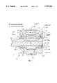
- FIG. 2Ais a similar view of actuator 50 according to this invention.
- Actuator 50provides the same functionality as actuator 20, FIG. 1, but with significant advantages.
- Actuator 50includes rotor 52 which comprises the passive member whose position is controlled by the excited member made up of a number of stator sectors such as sectors 60 and 80. The remaining sectors are not shown in this drawing, but are described below.
- Actuator 50accomplishes the same normal and tangential position control of rotor 52, as does the prior art device depicted in FIG. 1.
- the volume of back iron magnetic material in both the rotor and statoris significantly less than that of the prior art device.
- stator sector 60includes teeth 62 and 63 separated by slot 65, and slot 66 separating tooth 64 from tooth 63.
- Conductor 73is placed within slot 65, insulated from stator sector 60.
- Conductor 72is similarly placed within slot 66.
- the excitation currentis passed through conductors 73 and 72 in opposite directions as shown. The current passing through conductor 73 thus creates flux 73a having the direction shown.
- the current passing through conductor 72creates flux 72a having the opposite direction as shown.
- the two fluxes 72a and 73aadditively combine in tooth 63, and rotor tooth 54a.
- the fluxesseparate in the back iron area of sector 60 (in back of the slots). Since the flux in stator sector back iron 60a is half of that in tooth 63, back iron thickness b' need only be approximately half of the tooth width a'. Likewise, rotor back iron width d' need only be half of tooth width a'.
- the thickness of magnetic actuator 50is substantially less than the thickness of magnetic actuator 10, FIG. 1, while accomplishing the same rotor control force. Since the device materials are the same, it follows that the device mass is similarly reduced. This accomplishes an actuator with a greater force to size, or mass, ratio, and thus an actuator with greater functionality.
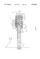
- FIG. 2BA portion 88 of stator sector 80 and rotor 52, is shown in detail in FIG. 2B.
- Magnetic actuator 50can be fabricated using micro-machining technologies well known in the art, in which primarily planar devices are created by selective deposition and etching of appropriate materials. This technique has the advantage of mass production of large quantities of devices of extremely small size at low unit cost. Devices made by micro-machining technologies are described in a paper entitled "A Fully Integrated Magnetically Actuated Micromachined Relay", pp. 231-234 of the June, 1996, Proceedings of the 1996 Solid State Sensor and Actuator Workshop, incorporated herein by reference. Devices of the type shown in FIG. 2A may be constructed using such techniques to accomplish a rotating disk approximately 1 cm diameter and of the order of 1-several mm thick (or, much smaller, or somewhat larger).
- Rotor 52has teeth 54 and slots 56.
- Stator section 80has teeth and slots of the same pitch.
- Conductorsare deposited in the slots, insulated from the slot walls.
- conductor 96is deposited in slot 92 on previously-deposited insulation layer 94 which lines the walls of slot 92.
- Slots 100, 102 and 104are identically constructed. The only difference is the current direction, as shown by arrows i.
- the single conductor per slotcould alternatively be subdivided into a number of conductors insulated from one another to reduce the required excitation current.
- FIGS. 3 through 5The integration of the actuators described above into a complete magnetic suspension system for a spinning wheel, is shown in FIGS. 3 through 5.
- Magnetic actuator 200FIG. 3, includes rotating wheel 220 sandwiched between identical stator portions 210 and 230.
- Stator portion 210includes 4 identical quadrant stator sectors 212, 214, 216 and 218.
- the reverse, inner (active) side of stator portion 210is shown in FIG. 4.
- stator sector 216is a circular quadrant sector defined by radii R 1 and R 2, and the circumference.
- Sector 216is configured to define a series of spaced, concentric, arc-shaped, alternating slots and ridges, for example slots 256 and 257 and ridges 254 and 252.
- a single conductor 240runs through each of the slots in sector 216 as shown. Since conductor 240 loops through the slots, when current is passed through conductor 240, the current is oppositely directed in adjacent slots, creating the distributed conductors shown in FIGS. 2A and 2B.
- FIG. 5One face of rotor 220 is shown in FIG. 5. The other face is identical.
- the alternating teeth and slotsare also created by a regular series of alternating, concentric, circular slots and ridges, for example slots 223 and 225, with ridge 226 therebetween.
- the rotor 220may be rotated in a known fashion using excitation members 222, FIG. 3 (electric conductors not shown), and the teeth and slots formed along its rim, shown in FIGS. 3 and 5.
- FIG. 6 and table 1together describe the control of the rotor in 5 degrees of freedom.
- the sixth degreeis the required rotor rotation which is controlled in a known fashion that does not form part of this invention.
- Also depicted in FIG. 6is the axes convention used.
- a selected quiescent, or bias, currentis passed through all of the stator sector conductors, creating essentially identical forces in each stator sector when the rotor is exactly centered.
- the z (normal to the rotor flat faces) direction attractive force of the actuator sector labeled B top of stator portion 210is equal to, but opposite in sign, that of the directly opposite actuator sector B bottom (not shown, of stator portion 230) while the x forces are equal and in the same direction (-x direction).
- the +z direction attractive force of the actuator sector labelled D topis equal to, but opposite in sign, to that of the directly opposite actuator sector D bottom , while the x forces are equal and in the same direction (+x direction). Thus, no net force is developed on the rotor.
- a similar situationapplies to the y-axis forces.
- +x-axis force only, without affecting the other forces and moments,is generated by increasing the current in the actuator conductors of, D top and D bottom , by an amount ⁇ i, and decreasing that in the conductors of B top and B bottom by ⁇ i.
- y-axis forcesare generated in a similar fashion.
- z-axis forces+z-axis force only, without affecting the other forces and moments, is generated by increasing the current in the conductors of actuator sectors A top , B top , C top and D top , by an amount ⁇ i, while decreasing the current in the conductors of A bottom , B bottom , C bottom and D bottom , by ⁇ i; the net x and y-axis forces and moments are unchanged.
- control logicis summarized in Table 1.
- the bias currentprovides the benefit of linearizing the force vs. control current relationship, which would otherwise be quadratic.
- FIG. 7depicts one possibility for sensing the relative position of rotor 300 and stator 400, for an active suspension control system useful in this invention.
- Capacitor electrodessuch as electrode 406 can be added to the teeth of stator 400, insulated from the material of the stator.
- the variable capacitance sensing accomplished using capacitorsis independent of the force application in the magnetic actuator, making the active control system easier to implement.
- the co-location of the force application devices and the sensing devicesalso simplifies the control system design.
- Non-limiting examplesinclude: continuously sensing the inductance of the actuator members (typically the stator so that the rotor can remain passive) while they are being used to generate force, or time-sharing the actuators so that they are used for forcing for a part of the time, and sensing for the balance of the time; and sharing the space allocated to the sensor and actuator stator, providing a portion for forcing and using the balance for sensing.
- This approach, and the time-sharing approachwould decrease the maximum force capability of the actuator, but would reduce the effect of the interaction of magnetic material non-linearities and forcing current variations on accuracy of position sensing.
- the stators themselvescan be effectively used for sensing the position of the rotor because their self-inductance changes with both tangential and normal motion; an output voltage proportional to the change in inductance, and thus in position, results when the actuators are used in a suitable bridge circuit or an equivalent design.
- the sensing sensitivitywill be maximum when the geometry is selected for maximum developed force, because both position sensing sensitivity and the developed force are directly proportional to the rate of change of inductance with position.
- the magnetic actuator and position control system of this inventioncan be used in situations that can benefit from precise control of the relative positions of members, at least one of which is movable.
- the designswhich lend themselves to planar fabrication technologies, may be implemented in electronic devices with electromechanical structures.
- One examplewould be a data storage disk drive.
- the read/write head of such drivesis desirably very finely controlled. Because of the nonrepeatable runout of the ball bearings, combined with the limited control bandwidth of the head position controller, typically used to support the disk of such drives, the heads cannot be precisely positioned over the track containing the recorded information. This limits track density, and thus the disk storage capacity, increasing the cost per stored bit.
- An actuator system of this inventionsituated close to the read/write head, could be used to provide high bandwidth precision control of the head position over a small position range, allowing the data tracks to be more narrow, and located closer together.
- the read/write heads widely used in the fieldare of thin film construction, and are fabricated using the same photolithographic electrodeposition technologies that may be used to fabricate the magnetic actuators of this invention. Such could allow the positioning and control afforded by this invention to be built into the disk read/write heads using the current head fabrication techniques.
Landscapes
- Engineering & Computer Science (AREA)
- Power Engineering (AREA)
- General Engineering & Computer Science (AREA)
- Mechanical Engineering (AREA)
- Linear Motors (AREA)
Abstract
Description
TABLE 1__________________________________________________________________________Magnetic Suspension Control LogicSector +F.sub.x -F.sub.x +F.sub.y -F.sub.y +F.sub.z -F.sub.Z +M.sub.x -M.sub.x +M.sub.y -M.sub.y__________________________________________________________________________A.sub.top +Δi -Δi +Δi -Δi +Δi -Δi +Δi -ΔiB.sub.top +Δi -Δi -Δi +ΔiC.sub.top -Δi +Δi +Δi -Δi -Δi +ΔiD.sub.top -Δi +Δi +Δi -Δi +Δi -ΔiA.sub.bottom +Δi -Δi -Δi +Δi -Δi +ΔiB.sub.bottom +Δi -Δi -Δi +Δi +Δi -ΔiC.sub.bottom -Δi +Δi -Δi +Δi +Δi -ΔiD.sub.bottom -Δi +Δi -Δi +Δi -Δi +Δi__________________________________________________________________________
Claims (16)
Priority Applications (1)
| Application Number | Priority Date | Filing Date | Title |
|---|---|---|---|
| US08/730,712US5959382A (en) | 1995-10-13 | 1996-10-15 | Magnetic actuator and position control system |
Applications Claiming Priority (2)
| Application Number | Priority Date | Filing Date | Title |
|---|---|---|---|
| US542495P | 1995-10-13 | 1995-10-13 | |
| US08/730,712US5959382A (en) | 1995-10-13 | 1996-10-15 | Magnetic actuator and position control system |
Publications (1)
| Publication Number | Publication Date |
|---|---|
| US5959382Atrue US5959382A (en) | 1999-09-28 |
Family
ID=26674351
Family Applications (1)
| Application Number | Title | Priority Date | Filing Date |
|---|---|---|---|
| US08/730,712Expired - Fee RelatedUS5959382A (en) | 1995-10-13 | 1996-10-15 | Magnetic actuator and position control system |
Country Status (1)
| Country | Link |
|---|---|
| US (1) | US5959382A (en) |
Cited By (22)
| Publication number | Priority date | Publication date | Assignee | Title |
|---|---|---|---|---|
| US6051897A (en)* | 1999-05-05 | 2000-04-18 | Synchro-Start Products, Inc. | Solenoid actuator with positional feedback |
| US20030025410A1 (en)* | 2001-07-31 | 2003-02-06 | Duhua Sun | Magnetic shaft for brushless D.C. motor |
| US6770995B1 (en)* | 2001-09-22 | 2004-08-03 | Gerald K. Foshage | Passive radial magnetic bearing |
| US6822369B2 (en)* | 2001-07-27 | 2004-11-23 | Ta-Ching Pong | Pulse propelling flat induction motor |
| US20050239220A1 (en)* | 2004-04-23 | 2005-10-27 | Dauwalter Charles R | Rate gyroscope and accelerometer multisensor, and method of fabricating same |
| US20060113848A1 (en)* | 2004-11-15 | 2006-06-01 | Studer Philip A | Linear brushless D.C. motor with stationary armature and field and with integralable magnetic suspension |
| US20060279538A1 (en)* | 1997-04-25 | 2006-12-14 | Chang Dean C | Design of force sensations for haptic feedback computer interfaces |
| US20080035435A1 (en)* | 2002-07-31 | 2008-02-14 | Immersion Corporation | System and Method for Providing Passive Haptic Feedback |
| US20080223249A1 (en)* | 2007-03-13 | 2008-09-18 | Studer Phillip A | Magnetic suspension system with integrable propulsion |
| US20090032350A1 (en)* | 2007-08-01 | 2009-02-05 | Sandor Wayne Shapery | System and method for capturing energy from a railcar |
| US7636080B2 (en) | 1995-12-01 | 2009-12-22 | Immersion Corporation | Networked applications including haptic feedback |
| US20100301979A1 (en)* | 2009-03-26 | 2010-12-02 | Philip Albert Studer | Method and system for transportation using a magnetic bearing structure |
| US7978186B2 (en)* | 1998-10-26 | 2011-07-12 | Immersion Corporation | Mechanisms for control knobs and other interface devices |
| US20110184601A1 (en)* | 2007-08-01 | 2011-07-28 | Sandor Wayne Shapery | System and method for operating a vehicle in multiple transportation networks |
| US8188989B2 (en) | 1996-11-26 | 2012-05-29 | Immersion Corporation | Control knob with multiple degrees of freedom and force feedback |
| US20130039786A1 (en)* | 2010-07-28 | 2013-02-14 | Danfoss Turbocor Compressors B.V. | Refrigerant compressor magnetic bearing |
| US8508469B1 (en) | 1995-12-01 | 2013-08-13 | Immersion Corporation | Networked applications including haptic feedback |
| US8820246B2 (en) | 2011-12-16 | 2014-09-02 | Sandor Wayne Shapery | Method and system for transportation using a rail structure |
| US8850989B2 (en) | 2010-12-03 | 2014-10-07 | Sandor Wayne Shapery | Magnetic levitation assembly |
| US9050896B2 (en)* | 2012-11-22 | 2015-06-09 | Paramount Pictures Corporation | Regenerative energy system for ground transportation vehicles |
| US10620017B2 (en)* | 2017-01-31 | 2020-04-14 | Rockwell Automation Technologies, Inc. | Curvilinear encoder system for position determination |
| US10892078B2 (en) | 2016-12-07 | 2021-01-12 | Mts Systems Corporation | Electric actuator |
Citations (24)
| Publication number | Priority date | Publication date | Assignee | Title |
|---|---|---|---|---|
| US3223867A (en)* | 1961-10-09 | 1965-12-14 | Gen Dynamics Corp | Axial air gap motor |
| US3225235A (en)* | 1961-09-29 | 1965-12-21 | Lee Royal | Dynamo-electric machine stator structure |
| US3355914A (en)* | 1964-11-02 | 1967-12-05 | Borg Warner | Clothes washing machine and linear motor therefor |
| US3735231A (en)* | 1971-06-28 | 1973-05-22 | B Sawyer | Linear magnetic drive system |
| US4081726A (en)* | 1976-01-05 | 1978-03-28 | Linear International Corporation | Electric motor |
| US4288709A (en)* | 1977-06-24 | 1981-09-08 | Exxon Research & Engineering Co. | High performance stepper motor |
| US4315171A (en)* | 1977-05-23 | 1982-02-09 | Ernest Schaeffer | Step motors |
| US4316394A (en)* | 1980-02-11 | 1982-02-23 | Sperry Corporation | Magnetically suspended free rotor gyroscope |
| US4353602A (en)* | 1977-01-12 | 1982-10-12 | Societe Europeenne De Propulsion | Axial electromagnetic bearing for smooth shafts of large diameter |
| US4483570A (en)* | 1982-02-26 | 1984-11-20 | Mitsubishi Denki Kabushiki Kaisha | Magnetic bearing arrangement for an artificial satellite |
| US4514674A (en)* | 1983-12-22 | 1985-04-30 | International Business Machines Corporation | Electromagnetic X-Y-Theta precision positioner |
| US4677327A (en)* | 1985-02-27 | 1987-06-30 | Diesel Kiki Co., Ltd. | Electromagnetic actuator with concentric coil resin fill |
| US4683391A (en)* | 1985-03-22 | 1987-07-28 | Nippon Seiko Kabushiki Kaisha | Magnetically floating actuator having angular positioning function |
| US4737753A (en)* | 1984-02-22 | 1988-04-12 | Portescap | Multipolar magnetization device |
| US4761574A (en)* | 1983-05-18 | 1988-08-02 | Shinko Electric Co., Ltd. | Linear pulse motor |
| US4794286A (en)* | 1986-04-03 | 1988-12-27 | Adept Technology, Inc. | Variable reluctance stepper motor |
| US4857782A (en)* | 1984-06-05 | 1989-08-15 | Mitsubishi Mining & Cement Co. Ltd. | Step motor |
| US4922145A (en)* | 1988-11-17 | 1990-05-01 | Eastman Kodak Company | Stepper motor |
| US5160877A (en)* | 1990-03-15 | 1992-11-03 | Matsushita Electric Works, Ltd. | Multiple degree-of-freedom positioning device |
| US5198711A (en)* | 1988-12-19 | 1993-03-30 | Boral Johns Perry Industries Pty. Ltd. | Electric motor for providing lifting force |
| US5216308A (en)* | 1989-05-25 | 1993-06-01 | Avcon-Advanced Controls Technology, Inc. | Magnetic bearing structure providing radial, axial and moment load bearing support for a rotatable shaft |
| US5237229A (en)* | 1992-04-16 | 1993-08-17 | Shinko Electric Co., Ltd. | Magnetic bearing device with a rotating magnetic field |
| US5334894A (en)* | 1991-05-14 | 1994-08-02 | Shinko Electric Co., Ltd. | Rotary pulse motor |
| US5396140A (en)* | 1993-05-28 | 1995-03-07 | Satcon Technology, Corp. | Parallel air gap serial flux A.C. electrical machine |
- 1996
- 1996-10-15USUS08/730,712patent/US5959382A/ennot_activeExpired - Fee Related
Patent Citations (24)
| Publication number | Priority date | Publication date | Assignee | Title |
|---|---|---|---|---|
| US3225235A (en)* | 1961-09-29 | 1965-12-21 | Lee Royal | Dynamo-electric machine stator structure |
| US3223867A (en)* | 1961-10-09 | 1965-12-14 | Gen Dynamics Corp | Axial air gap motor |
| US3355914A (en)* | 1964-11-02 | 1967-12-05 | Borg Warner | Clothes washing machine and linear motor therefor |
| US3735231A (en)* | 1971-06-28 | 1973-05-22 | B Sawyer | Linear magnetic drive system |
| US4081726A (en)* | 1976-01-05 | 1978-03-28 | Linear International Corporation | Electric motor |
| US4353602A (en)* | 1977-01-12 | 1982-10-12 | Societe Europeenne De Propulsion | Axial electromagnetic bearing for smooth shafts of large diameter |
| US4315171A (en)* | 1977-05-23 | 1982-02-09 | Ernest Schaeffer | Step motors |
| US4288709A (en)* | 1977-06-24 | 1981-09-08 | Exxon Research & Engineering Co. | High performance stepper motor |
| US4316394A (en)* | 1980-02-11 | 1982-02-23 | Sperry Corporation | Magnetically suspended free rotor gyroscope |
| US4483570A (en)* | 1982-02-26 | 1984-11-20 | Mitsubishi Denki Kabushiki Kaisha | Magnetic bearing arrangement for an artificial satellite |
| US4761574A (en)* | 1983-05-18 | 1988-08-02 | Shinko Electric Co., Ltd. | Linear pulse motor |
| US4514674A (en)* | 1983-12-22 | 1985-04-30 | International Business Machines Corporation | Electromagnetic X-Y-Theta precision positioner |
| US4737753A (en)* | 1984-02-22 | 1988-04-12 | Portescap | Multipolar magnetization device |
| US4857782A (en)* | 1984-06-05 | 1989-08-15 | Mitsubishi Mining & Cement Co. Ltd. | Step motor |
| US4677327A (en)* | 1985-02-27 | 1987-06-30 | Diesel Kiki Co., Ltd. | Electromagnetic actuator with concentric coil resin fill |
| US4683391A (en)* | 1985-03-22 | 1987-07-28 | Nippon Seiko Kabushiki Kaisha | Magnetically floating actuator having angular positioning function |
| US4794286A (en)* | 1986-04-03 | 1988-12-27 | Adept Technology, Inc. | Variable reluctance stepper motor |
| US4922145A (en)* | 1988-11-17 | 1990-05-01 | Eastman Kodak Company | Stepper motor |
| US5198711A (en)* | 1988-12-19 | 1993-03-30 | Boral Johns Perry Industries Pty. Ltd. | Electric motor for providing lifting force |
| US5216308A (en)* | 1989-05-25 | 1993-06-01 | Avcon-Advanced Controls Technology, Inc. | Magnetic bearing structure providing radial, axial and moment load bearing support for a rotatable shaft |
| US5160877A (en)* | 1990-03-15 | 1992-11-03 | Matsushita Electric Works, Ltd. | Multiple degree-of-freedom positioning device |
| US5334894A (en)* | 1991-05-14 | 1994-08-02 | Shinko Electric Co., Ltd. | Rotary pulse motor |
| US5237229A (en)* | 1992-04-16 | 1993-08-17 | Shinko Electric Co., Ltd. | Magnetic bearing device with a rotating magnetic field |
| US5396140A (en)* | 1993-05-28 | 1995-03-07 | Satcon Technology, Corp. | Parallel air gap serial flux A.C. electrical machine |
Non-Patent Citations (2)
| Title |
|---|
| "A Fully Integrated Magnetically Acuated Micromachined Relay", pp. 231-234 of the Jun. 1996, Proceedings of the 1996 Solid State Sensor and Actuator Workshop, by William P. Taylor, Mark G. Allen and Charles R. Dauwalter. |
| A Fully Integrated Magnetically Acuated Micromachined Relay , pp. 231 234 of the Jun. 1996, Proceedings of the 1996 Solid State Sensor and Actuator Workshop, by William P. Taylor, Mark G. Allen and Charles R. Dauwalter.* |
Cited By (48)
| Publication number | Priority date | Publication date | Assignee | Title |
|---|---|---|---|---|
| US8508469B1 (en) | 1995-12-01 | 2013-08-13 | Immersion Corporation | Networked applications including haptic feedback |
| US8072422B2 (en) | 1995-12-01 | 2011-12-06 | Immersion Corporation | Networked applications including haptic feedback |
| US7636080B2 (en) | 1995-12-01 | 2009-12-22 | Immersion Corporation | Networked applications including haptic feedback |
| US8188989B2 (en) | 1996-11-26 | 2012-05-29 | Immersion Corporation | Control knob with multiple degrees of freedom and force feedback |
| US20060279538A1 (en)* | 1997-04-25 | 2006-12-14 | Chang Dean C | Design of force sensations for haptic feedback computer interfaces |
| US8717287B2 (en) | 1997-04-25 | 2014-05-06 | Immersion Corporation | Force sensations for haptic feedback computer interfaces |
| US20100201502A1 (en)* | 1997-04-25 | 2010-08-12 | Immersion Corporation | Design of Force Sensations For Haptic Feedback Computer Interfaces |
| US7701438B2 (en) | 1997-04-25 | 2010-04-20 | Immersion Corporation | Design of force sensations for haptic feedback computer interfaces |
| US7978186B2 (en)* | 1998-10-26 | 2011-07-12 | Immersion Corporation | Mechanisms for control knobs and other interface devices |
| US6051897A (en)* | 1999-05-05 | 2000-04-18 | Synchro-Start Products, Inc. | Solenoid actuator with positional feedback |
| WO2004059827A3 (en)* | 2001-07-27 | 2005-03-10 | Ta-Ching Pong | Pulse propelling flat induction motor |
| US6822369B2 (en)* | 2001-07-27 | 2004-11-23 | Ta-Ching Pong | Pulse propelling flat induction motor |
| CN100353658C (en)* | 2001-07-27 | 2007-12-05 | 彭大庆 | Pulse type flat induction motor device |
| US6787956B2 (en)* | 2001-07-31 | 2004-09-07 | Shanghai Yen Sun Electrical Industry Co., Ltd. | Magnetic shaft for brushless D.C. motor |
| US20030025410A1 (en)* | 2001-07-31 | 2003-02-06 | Duhua Sun | Magnetic shaft for brushless D.C. motor |
| US6770995B1 (en)* | 2001-09-22 | 2004-08-03 | Gerald K. Foshage | Passive radial magnetic bearing |
| US20080036736A1 (en)* | 2002-07-31 | 2008-02-14 | Immersion Corporation | System and Method for Providing Passive Haptic Feedback |
| US9274600B2 (en) | 2002-07-31 | 2016-03-01 | Immersion Corporation | System and method for providing passive haptic feedback |
| US8248363B2 (en) | 2002-07-31 | 2012-08-21 | Immersion Corporation | System and method for providing passive haptic feedback |
| US20080036735A1 (en)* | 2002-07-31 | 2008-02-14 | Immersion Corporation | System and Method for Providing Passive Haptic Feedback |
| US20080035435A1 (en)* | 2002-07-31 | 2008-02-14 | Immersion Corporation | System and Method for Providing Passive Haptic Feedback |
| US7356922B2 (en)* | 2004-04-23 | 2008-04-15 | Milli Sensors Systems & Actuators, Inc. | Method of fabricating a rate gyroscope and accelerometer multisensor |
| US20050239220A1 (en)* | 2004-04-23 | 2005-10-27 | Dauwalter Charles R | Rate gyroscope and accelerometer multisensor, and method of fabricating same |
| US7617779B2 (en)* | 2004-11-15 | 2009-11-17 | Sandor Shapery | Linear brushless D.C. motor with stationary armature and field and with integratable magnetic suspension |
| US20060113848A1 (en)* | 2004-11-15 | 2006-06-01 | Studer Philip A | Linear brushless D.C. motor with stationary armature and field and with integralable magnetic suspension |
| US20080223249A1 (en)* | 2007-03-13 | 2008-09-18 | Studer Phillip A | Magnetic suspension system with integrable propulsion |
| US7963228B2 (en) | 2007-03-13 | 2011-06-21 | Sandor Wayne Shapery | Magnetic suspension system with integrable propulsion |
| US8453580B2 (en) | 2007-03-13 | 2013-06-04 | Sandor Wayne Shapery | Magnetic suspension system with integrable propulsion |
| US8069792B2 (en) | 2007-08-01 | 2011-12-06 | Sandor Wayne Shapery | System and method for capturing energy from a railcar |
| US8528487B2 (en) | 2007-08-01 | 2013-09-10 | Sandor Wayne Shapery Wayne Shapery | System and method for operating a vehicle in multiple transportation networks |
| US20090032350A1 (en)* | 2007-08-01 | 2009-02-05 | Sandor Wayne Shapery | System and method for capturing energy from a railcar |
| US20110184601A1 (en)* | 2007-08-01 | 2011-07-28 | Sandor Wayne Shapery | System and method for operating a vehicle in multiple transportation networks |
| US20100301979A1 (en)* | 2009-03-26 | 2010-12-02 | Philip Albert Studer | Method and system for transportation using a magnetic bearing structure |
| US8324777B2 (en) | 2009-03-26 | 2012-12-04 | Sandor Wayne Shapery | Method and system for transportation using a magnetic bearing structure |
| US20130039786A1 (en)* | 2010-07-28 | 2013-02-14 | Danfoss Turbocor Compressors B.V. | Refrigerant compressor magnetic bearing |
| US9624939B2 (en)* | 2010-07-28 | 2017-04-18 | Danfoss A/S | Refrigerant compressor magnetic bearing |
| US8850989B2 (en) | 2010-12-03 | 2014-10-07 | Sandor Wayne Shapery | Magnetic levitation assembly |
| US8820246B2 (en) | 2011-12-16 | 2014-09-02 | Sandor Wayne Shapery | Method and system for transportation using a rail structure |
| US20170005607A1 (en)* | 2012-11-22 | 2017-01-05 | Paramount Pictures Corporation | Regenerative Energy System for Ground Transportation Vehicles |
| US9457687B2 (en)* | 2012-11-22 | 2016-10-04 | Paramount Pictures Corporation | Regenerative energy system for ground transportation vehicles |
| US9050896B2 (en)* | 2012-11-22 | 2015-06-09 | Paramount Pictures Corporation | Regenerative energy system for ground transportation vehicles |
| US9748885B2 (en)* | 2012-11-22 | 2017-08-29 | Paramount Pictures Corporation | Regenerative energy system for ground transportation vehicles |
| US10135376B2 (en)* | 2012-11-22 | 2018-11-20 | Paramount Pictures Corporation | Regenerative energy system for ground transportation vehicles |
| US20190052213A1 (en)* | 2012-11-22 | 2019-02-14 | Paramount Pictures Corporation | Regenerative energy system for ground transportation vehicles |
| US10594244B2 (en)* | 2012-11-22 | 2020-03-17 | Paramount Pictures Corporation | Regenerative energy system for ground transportation vehicles |
| US10892078B2 (en) | 2016-12-07 | 2021-01-12 | Mts Systems Corporation | Electric actuator |
| US10620017B2 (en)* | 2017-01-31 | 2020-04-14 | Rockwell Automation Technologies, Inc. | Curvilinear encoder system for position determination |
| US10809101B2 (en) | 2017-01-31 | 2020-10-20 | Rockwell Automation Technologies, Inc. | Curvilinear encoder system for position determination |
Similar Documents
| Publication | Publication Date | Title |
|---|---|---|
| US5959382A (en) | Magnetic actuator and position control system | |
| US6114788A (en) | Motor/active magnetic bearing combination structure | |
| US5955800A (en) | Levitation systems | |
| US6583524B2 (en) | Micro-mover with balanced dynamics | |
| JP4024382B2 (en) | Magnetic bearing device | |
| US6122149A (en) | Magnetic microactuator and inductive sensor having shaped pole configuration | |
| US6239952B1 (en) | Microactuator suspension with multiple “I” shaped microbeams | |
| US5267110A (en) | Rotary actuator for a direct access storage device | |
| US4490635A (en) | Pure torque, limited displacement transducer | |
| JPS61218355A (en) | Magnetically levitating actuator having rotation positioning function | |
| KR960000832B1 (en) | Linear actuator | |
| EP0732694B1 (en) | Integrated data storage disk and disk drive | |
| US5523911A (en) | Minimum bearing load, high precision actuator arm with force couple actuation | |
| Horsley et al. | Microfabricated electrostatic actuators for hard disk drives | |
| US5557152A (en) | 2-Pole single or dual coil moving magnet motor with moving back iron | |
| US6388413B1 (en) | Head switch seek on disc drives with multiple recording heads | |
| Miu et al. | Silicon micromachined SCALED technology | |
| JP3946255B2 (en) | Accelerometer star lead | |
| US20020054458A1 (en) | Moving magnet voice coil motor using halbach arrays | |
| JPS6146684B2 (en) | ||
| JP3684118B2 (en) | Electromagnetic actuator, optical scanner | |
| EP0025446A1 (en) | Two degree of freedom gyro having a permanent magnet motor. | |
| JP2003059219A (en) | Micro-actuator, read/write head, head gimbal assembly, actuator arm for disk drive, and the disk drive | |
| US4558244A (en) | Micro stepping motor | |
| US5907455A (en) | Distributed spindle motor integrated with disc |
Legal Events
| Date | Code | Title | Description |
|---|---|---|---|
| AS | Assignment | Owner name:MILLI SENSOR SYSTEMS AND ACTUATORS, INC., MASSACHU Free format text:(ASSIGNMENT OF ASSIGNOR'S INTEREST) RE-RECORD FOR MICROFILM PURPOSES. THE COVER SHEET AND DOCUMENT DO NOT MATCH ON REEL 8277 FRAME 503.;ASSIGNOR:DAUWALTER, CHARLES R.;REEL/FRAME:008340/0343 Effective date:19961011 Owner name:MILLI SENSOR SYSTEMS AND ACTUATORS, INC., MASSACHU Free format text:ASSIGNMENT OF ASSIGNORS INTEREST;ASSIGNOR:DAUWALTER, CHARLES R.;REEL/FRAME:008277/0503 Effective date:19961011 Owner name:MILLI SENSOR SYSTEMS AND ACTUATORS, INC., MASSACHU Free format text:ASSIGNMENT OF ASSIGNORS INTEREST;ASSIGNOR:DAUWALTER, CHARLES R.;REEL/FRAME:008375/0162 Effective date:19961011 | |
| FPAY | Fee payment | Year of fee payment:4 | |
| REMI | Maintenance fee reminder mailed | ||
| FPAY | Fee payment | Year of fee payment:8 | |
| SULP | Surcharge for late payment | Year of fee payment:7 | |
| FEPP | Fee payment procedure | Free format text:PAYOR NUMBER ASSIGNED (ORIGINAL EVENT CODE: ASPN); ENTITY STATUS OF PATENT OWNER: SMALL ENTITY | |
| REMI | Maintenance fee reminder mailed | ||
| LAPS | Lapse for failure to pay maintenance fees | ||
| STCH | Information on status: patent discontinuation | Free format text:PATENT EXPIRED DUE TO NONPAYMENT OF MAINTENANCE FEES UNDER 37 CFR 1.362 | |
| FP | Lapsed due to failure to pay maintenance fee | Effective date:20110928 |