US5959250A - Sealing device for telecommunications equipment enclosures - Google Patents
Sealing device for telecommunications equipment enclosuresDownload PDFInfo
- Publication number
- US5959250A US5959250AUS09/104,581US10458198AUS5959250AUS 5959250 AUS5959250 AUS 5959250AUS 10458198 AUS10458198 AUS 10458198AUS 5959250 AUS5959250 AUS 5959250A
- Authority
- US
- United States
- Prior art keywords
- inserts
- wires
- aperture
- lid
- base
- Prior art date
- Legal status (The legal status is an assumption and is not a legal conclusion. Google has not performed a legal analysis and makes no representation as to the accuracy of the status listed.)
- Expired - Lifetime
Links
Images


Classifications
- H—ELECTRICITY
- H02—GENERATION; CONVERSION OR DISTRIBUTION OF ELECTRIC POWER
- H02G—INSTALLATION OF ELECTRIC CABLES OR LINES, OR OF COMBINED OPTICAL AND ELECTRIC CABLES OR LINES
- H02G3/00—Installations of electric cables or lines or protective tubing therefor in or on buildings, equivalent structures or vehicles
- H02G3/02—Details
- H02G3/08—Distribution boxes; Connection or junction boxes
- H02G3/088—Dustproof, splashproof, drip-proof, waterproof, or flameproof casings or inlets
Definitions
- the present inventionrelates to telecommunications equipment, and, in particular, to enclosures for housing and protecting telecommunications equipment.
- a building entrance protectoris an enclosure used to house and protect telecommunications equipment.
- a BEPmay house the components used to interface between a multi-wire cable providing telephone service to a building and the twisted pairs of copper wire for individual telephones distributed throughout the building. These interface components may include connectors, such as insulation displacement connectors (IDCs), as well as electrical isolation components, such as high-voltage/high-current plug-in protectors.
- the BEPmay have two or more hinged pieces that define one or more different compartments within the BEP for such functions as breaking out wires from the multi-wire cable, splicing two cables together, connecting cable wires to electrical isolation components, connecting the electrical isolation components to IDC connectors, and terminating the twisted pairs at the IDC connectors.
- a conventional BEPhas one or more apertures in its side walls through which individual or bundles of twisted pairs are fed to connect the various individual telephones to the interface components housed in the BEP.
- BEPsare usually built in one or more standard configurations, each of which is designed to handle a variety of applications in which the number of twisted pairs or other wires fed through the BEP apertures can vary widely. Since an aperture is designed to accommodate a specified maximum number of wires, when fewer than the maximum number of wires are fed through the aperture, gaps will exist between the wires and the edges of the BEP that define the aperture, through which dust and other contaminants can enter the BEP interior. Even when the aperture is used with the specified maximum number of wires, there will still typically be gaps that will allow contaminants to pass. Over time, accumulations of dust and other such contaminants can adversely affect the ability of the interface components housed within a BEP to continue to perform their desired functions.
- rubber grommetsare inserted in the apertures to limit the amount of dust that can enter the BEP interior through the apertures.
- Such grommetsmay be designed with removable material to increase the size of the opening in the grommet. According to these designs, more and more grommet material can be removed from the grommet to accommodate more and more wires as the number of wires fed through an aperture increases.
- One limitation of such a schemeis that it is irreversible. Once grommet material is removed, it cannot be replaced, if, for example, the number of wires to be accommodated by the aperture decreases, rather than increases, over time. The result is once again gaps between the wires and the remaining grommet material through which dust can pass. Alternatively, a new grommet can be used, but this would increase the cost of operations.
- the present inventionis directed to a scheme for reducing the amount of dust and other contaminants that can enter a BEP through the apertures defined in the BEP side walls through which twisted pairs and other wires are fed.
- the present inventionis an enclosure for telecommunications equipment, comprising a base and a lid pivotally connected to the base.
- the enclosurehas an aperture defined by aperture edges through which one or more wires can be fed.
- a first elastically deformable insertis attached to a mounting surface on the base and a second elastically deformable insert is attached to a mounting surface on the lid, both adjacent to the aperture, such that when the lid is closed, the first and second inserts deform under contact with each other and with any wires fed through the aperture to reduce the size of gaps between the wires and the aperture edges.
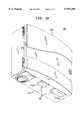
- FIGS. 1A and 1Bshow a building entrance protector in its closed and open states, respectively, that can be used with one embodiment of the present invention
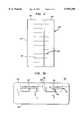
- FIG. 2shows a side view of two inserts, according to one embodiment of the present invention.
- FIGS. 3A and 3Bshow side and cross-section views, respectively, of a building entrance protector in which inserts have been mounted, according to the present invention.
- FIGS. 1A and 1Bshow a building entrance protector 100 in its closed and open states, respectively, that can be used with one embodiment of the present invention.
- BEP 100has a base 102 and a pivoting lid 104 that provides the user with access to the interior of BEP 100.
- lid 104When lid 104 is closed, troughs 106 in base 102 define apertures in BEP 100 through which wires can be fed. Wire retainers may be inserted within troughs 106 to keep the wires in place when lid 104 is opened and to prevent crimping or "guillotining" of wires between the side walls of base 102 and lid 104, when lid 104 is closed.
- two elastically deformable insertsare attached to BEP 100 for each trough 106--one insert attached to a mounting surface on the BEP base and the other insert attached to a mounting surface at a corresponding location on the BEP lid, where the mounting surfaces are as close as practicable to the trough.
- the insertsare deformed--by contact with each other and with any wires held by the wire retainer in the trough--to reduce the size of gaps that would otherwise exist between the wires and the edges of the aperture.
- FIG. 2shows a side view of two inserts 202 and 204, according to one embodiment of the present invention.
- Each inserthas an adhesive backing 206 on one side to attach the insert to the appropriate BEP mounting surface.
- each inserthas one or more slots 208, substantially perpendicular to the adhesive-backed sides. These slots, which may be made by cutting the inserts without removing any of the insert material, provide increased localized deformability for possible non-continuous deformations, thereby providing better sealing characteristics.
- FIG. 3Ashows a side view of a building entrance protector, similar to a side view of side 108 of BEP 100 of FIG. 1, in which inserts, similar to those shown in FIG. 2, have been mounted, according to the present invention, adjacent to the wire retainers 302 that are mounted within the BEP troughs.
- FIG. 3Bshows a cross-section view of the BEP of FIG. 3A, similar to a cross section view of side 110 of BEP 100 of FIG. 1.
- the larger insert 202is attached to the BEP lid 104, while the smaller insert 204 is attached to a mounting ledge 308 in the BEP base 102, both inserts preferably as close to the trough as practicable (as shown in FIG. 3B).
- the combined height of the two insertsis preferably larger than the distance between their respective mounting surfaces when the BEP lid is closed.
- the insertswill deform as a result of their mutual contact to provide a substantially dust-free seal in the aperture.
- FIGS. 3A and 3Bshow the level of insert 204, both in its uncompressed state when the lid is opened (304) and in its compressed state when the lid is closed (306).
- wires 310are fed through the aperture, insert compression will be greater and have deformations that follow the existing contours to maintain the substantially dust-free seal.
- the insertsare preferably made of an elastic material that recovers its uncompressed shape when the lid is opened. In this way, the numbers of wires fed through the aperture can be either increased or decreased over time without adversely affecting the ability of the inserts to provide good sealing characteristics.
- the present inventionhas advantages over conventional grommet-based schemes for sealing apertures in building entrance protectors. For example, the present invention does not require manipulation of the grommets to remove grommet material when the number of wires increase. Nor does the present invention require the costly replacement of grommets when the number of wires decreases.
- the present inventionhas been described in the context of a building entrance protector having a base and a lid that define a single interior chamber, those skilled in the art will understand that the BEP may have intermediate levels that may define, with the lid and the base, two or more different interior chambers.
- the terms "base” and “lid”are intended as relative terms indicating two adjacent levels that define one or more apertures in the BEP.
Landscapes
- Engineering & Computer Science (AREA)
- Architecture (AREA)
- Civil Engineering (AREA)
- Structural Engineering (AREA)
- Installation Of Indoor Wiring (AREA)
Abstract
Description
Claims (8)
Priority Applications (1)
| Application Number | Priority Date | Filing Date | Title |
|---|---|---|---|
| US09/104,581US5959250A (en) | 1998-06-25 | 1998-06-25 | Sealing device for telecommunications equipment enclosures |
Applications Claiming Priority (1)
| Application Number | Priority Date | Filing Date | Title |
|---|---|---|---|
| US09/104,581US5959250A (en) | 1998-06-25 | 1998-06-25 | Sealing device for telecommunications equipment enclosures |
Publications (1)
| Publication Number | Publication Date |
|---|---|
| US5959250Atrue US5959250A (en) | 1999-09-28 |
Family
ID=22301245
Family Applications (1)
| Application Number | Title | Priority Date | Filing Date |
|---|---|---|---|
| US09/104,581Expired - LifetimeUS5959250A (en) | 1998-06-25 | 1998-06-25 | Sealing device for telecommunications equipment enclosures |
Country Status (1)
| Country | Link |
|---|---|
| US (1) | US5959250A (en) |
Cited By (30)
| Publication number | Priority date | Publication date | Assignee | Title |
|---|---|---|---|---|
| US6150607A (en)* | 1997-07-03 | 2000-11-21 | Robert Bosch Gmbh | Cable bushing for connecting at least one cable of a gas sensor |
| US6242697B1 (en)* | 1999-05-28 | 2001-06-05 | General Electric Company | Molded plastic enclosure |
| US6274812B1 (en)* | 1999-12-17 | 2001-08-14 | Avaya Technology Corp. | Cable sealing device system |
| DE20007593U1 (en)* | 2000-04-27 | 2001-09-06 | Vötsch Industrietechnik GmbH, 35447 Reiskirchen | Implementation for at least one line |
| USD448733S1 (en) | 2000-10-09 | 2001-10-02 | Telefonaktiebolaget L.M. Ericsson | Electronics housing |
| USD450664S1 (en) | 2000-10-09 | 2001-11-20 | Telefonaktiebolaget L.M. Ericsson | Cover for electronics housing |
| US6462275B1 (en)* | 1999-12-17 | 2002-10-08 | Avaya Technology Corp. | Cable sealing device and system |
| US20030161113A1 (en)* | 2002-02-28 | 2003-08-28 | Wrycraft Sean Conor | Rack-mounted module access |
| US20050072778A1 (en)* | 2003-10-07 | 2005-04-07 | Hull Eric G. | Outlet box knockout |
| US20050092506A1 (en)* | 2003-10-07 | 2005-05-05 | The Lamson & Sessions Co. | Outlet box knockout |
| USD507241S1 (en)* | 2002-08-21 | 2005-07-12 | Juergen Koessler | Junction box |
| USD508027S1 (en)* | 2004-12-13 | 2005-08-02 | Yuen Kim Shingt | Power distribution center housing |
| US6953890B2 (en) | 2002-11-15 | 2005-10-11 | Juergen Koessler | Junction box |
| USD512697S1 (en)* | 2003-12-08 | 2005-12-13 | Extreme Networks | Housing for electronic device |
| USD520001S1 (en)* | 2004-07-30 | 2006-05-02 | Fuji Photo Film Co., Ltd. | Image data wireless transmitter |
| US20060096774A1 (en)* | 2004-11-08 | 2006-05-11 | Vo Chanh C | Environmental seal for network interface device |
| ES2259916A1 (en)* | 2005-03-22 | 2006-10-16 | Jesus Santiago Gomez Elvira | Box for connections and electrical mechanisms. (Machine-translation by Google Translate, not legally binding) |
| US20080197129A1 (en)* | 2007-02-16 | 2008-08-21 | Chris Gosche | Telecommunications Enclosure System |
| US20090211778A1 (en)* | 2008-02-22 | 2009-08-27 | Thomas & Betts International, Inc. | Electrical Box Cover With Insect Guard |
| US20090242230A1 (en)* | 2008-03-25 | 2009-10-01 | Hebert Robert J | Electrical connector canopy |
| US20100200263A1 (en)* | 2009-02-06 | 2010-08-12 | Alen Tseng | Electrical junction box for tool-less installation of power cables |
| US20110083873A1 (en)* | 2009-10-14 | 2011-04-14 | Panduit Corp. | Network Cabinet Fitting System |
| US20150153055A1 (en)* | 2012-10-19 | 2015-06-04 | Msd Research, Inc. | Drain line access device with interior overflow safety switch |
| US9344803B1 (en) | 2012-06-21 | 2016-05-17 | Gonzalo Palenzuela | Easy mounting configuration for loudspeaker |
| US9742169B1 (en)* | 2016-06-28 | 2017-08-22 | Sumitomo Wiring Systems, Ltd. | Junction box assemblies with sequentially elevated openings |
| US20210273354A1 (en)* | 2020-02-27 | 2021-09-02 | Amtrol Licensing Inc. | Electrical cover for wired devices |
| US11619790B2 (en)* | 2018-09-21 | 2023-04-04 | Commscope Technologies Llc | Fiber optic cable sealing device |
| USD1042356S1 (en)* | 2024-02-21 | 2024-09-17 | Chengquan Liu | Electrical box |
| USD1069729S1 (en)* | 2022-09-12 | 2025-04-08 | Magen Eco Energy A.c.s Ltd. | Junction box for pipework |
| USD1073625S1 (en)* | 2023-08-09 | 2025-05-06 | Yueqing Daier Electron Co., Ltd. | Power outlet box |
Citations (8)
| Publication number | Priority date | Publication date | Assignee | Title |
|---|---|---|---|---|
| US3873757A (en)* | 1974-04-08 | 1975-03-25 | Bell Telephone Labor Inc | Communications circuit protector |
| US3927785A (en)* | 1974-10-24 | 1975-12-23 | Union Insulating Co | Electrical wiring box structure |
| US4109095A (en)* | 1976-10-28 | 1978-08-22 | Mulberry Metal Products, Inc. | Weatherproof electrical outlet box cover |
| US4424407A (en)* | 1981-11-30 | 1984-01-03 | Barbic Mark J | Electrical outlet safety cover |
| US4733015A (en)* | 1986-05-05 | 1988-03-22 | Emerson Electric Co. | Termination assembly |
| WO1994022195A1 (en)* | 1993-03-15 | 1994-09-29 | Walter Rose Gmbh & Co Kg | Telecommunications cable sleeve kit |
| US5378174A (en)* | 1993-03-18 | 1995-01-03 | The Whitaker Corporation | Enclosure for variety of terminal blocks |
| US5568362A (en)* | 1992-09-25 | 1996-10-22 | Atlas Copco Tools Ab | Cabinet for housing electronic equipment connectable to machines or power tools for performing operations |
- 1998
- 1998-06-25USUS09/104,581patent/US5959250A/ennot_activeExpired - Lifetime
Patent Citations (8)
| Publication number | Priority date | Publication date | Assignee | Title |
|---|---|---|---|---|
| US3873757A (en)* | 1974-04-08 | 1975-03-25 | Bell Telephone Labor Inc | Communications circuit protector |
| US3927785A (en)* | 1974-10-24 | 1975-12-23 | Union Insulating Co | Electrical wiring box structure |
| US4109095A (en)* | 1976-10-28 | 1978-08-22 | Mulberry Metal Products, Inc. | Weatherproof electrical outlet box cover |
| US4424407A (en)* | 1981-11-30 | 1984-01-03 | Barbic Mark J | Electrical outlet safety cover |
| US4733015A (en)* | 1986-05-05 | 1988-03-22 | Emerson Electric Co. | Termination assembly |
| US5568362A (en)* | 1992-09-25 | 1996-10-22 | Atlas Copco Tools Ab | Cabinet for housing electronic equipment connectable to machines or power tools for performing operations |
| WO1994022195A1 (en)* | 1993-03-15 | 1994-09-29 | Walter Rose Gmbh & Co Kg | Telecommunications cable sleeve kit |
| US5378174A (en)* | 1993-03-18 | 1995-01-03 | The Whitaker Corporation | Enclosure for variety of terminal blocks |
Cited By (41)
| Publication number | Priority date | Publication date | Assignee | Title |
|---|---|---|---|---|
| US6150607A (en)* | 1997-07-03 | 2000-11-21 | Robert Bosch Gmbh | Cable bushing for connecting at least one cable of a gas sensor |
| US6242697B1 (en)* | 1999-05-28 | 2001-06-05 | General Electric Company | Molded plastic enclosure |
| US6274812B1 (en)* | 1999-12-17 | 2001-08-14 | Avaya Technology Corp. | Cable sealing device system |
| US6462275B1 (en)* | 1999-12-17 | 2002-10-08 | Avaya Technology Corp. | Cable sealing device and system |
| DE20007593U1 (en)* | 2000-04-27 | 2001-09-06 | Vötsch Industrietechnik GmbH, 35447 Reiskirchen | Implementation for at least one line |
| USD448733S1 (en) | 2000-10-09 | 2001-10-02 | Telefonaktiebolaget L.M. Ericsson | Electronics housing |
| USD450664S1 (en) | 2000-10-09 | 2001-11-20 | Telefonaktiebolaget L.M. Ericsson | Cover for electronics housing |
| US6842349B2 (en)* | 2002-02-28 | 2005-01-11 | Sun Microsystems, Inc. | Rack-mounted module access |
| US20030161113A1 (en)* | 2002-02-28 | 2003-08-28 | Wrycraft Sean Conor | Rack-mounted module access |
| USD507241S1 (en)* | 2002-08-21 | 2005-07-12 | Juergen Koessler | Junction box |
| US6953890B2 (en) | 2002-11-15 | 2005-10-11 | Juergen Koessler | Junction box |
| US7353961B2 (en) | 2003-10-07 | 2008-04-08 | The Lamson & Sessions Co. | Outlet box knockout |
| US20050072778A1 (en)* | 2003-10-07 | 2005-04-07 | Hull Eric G. | Outlet box knockout |
| US20050092506A1 (en)* | 2003-10-07 | 2005-05-05 | The Lamson & Sessions Co. | Outlet box knockout |
| US7575122B2 (en) | 2003-10-07 | 2009-08-18 | The Lamson & Sessions Co. | Outlet box knockout |
| USD512697S1 (en)* | 2003-12-08 | 2005-12-13 | Extreme Networks | Housing for electronic device |
| USD520001S1 (en)* | 2004-07-30 | 2006-05-02 | Fuji Photo Film Co., Ltd. | Image data wireless transmitter |
| US7414190B2 (en)* | 2004-11-08 | 2008-08-19 | Corning Cable Systems Llc | Environmental seal for network interface device |
| US20060096774A1 (en)* | 2004-11-08 | 2006-05-11 | Vo Chanh C | Environmental seal for network interface device |
| USD508027S1 (en)* | 2004-12-13 | 2005-08-02 | Yuen Kim Shingt | Power distribution center housing |
| ES2259916A1 (en)* | 2005-03-22 | 2006-10-16 | Jesus Santiago Gomez Elvira | Box for connections and electrical mechanisms. (Machine-translation by Google Translate, not legally binding) |
| ES2259916B2 (en)* | 2005-03-22 | 2007-11-01 | Jesus Santiago Gomez Elvira | BOX FOR ELECTRICAL CONNECTIONS AND MECHANISMS. |
| US7815065B2 (en) | 2007-02-16 | 2010-10-19 | Chris Gosche | Telecommunications enclosure system |
| US20080197129A1 (en)* | 2007-02-16 | 2008-08-21 | Chris Gosche | Telecommunications Enclosure System |
| US8110743B2 (en) | 2008-02-22 | 2012-02-07 | Thomas & Betts International, Inc. | Electrical box cover with insect guard |
| US20090211778A1 (en)* | 2008-02-22 | 2009-08-27 | Thomas & Betts International, Inc. | Electrical Box Cover With Insect Guard |
| US20090242230A1 (en)* | 2008-03-25 | 2009-10-01 | Hebert Robert J | Electrical connector canopy |
| US20100200263A1 (en)* | 2009-02-06 | 2010-08-12 | Alen Tseng | Electrical junction box for tool-less installation of power cables |
| US20110083873A1 (en)* | 2009-10-14 | 2011-04-14 | Panduit Corp. | Network Cabinet Fitting System |
| US8791367B2 (en) | 2009-10-14 | 2014-07-29 | Panduit Corp. | Network cabinet fitting system |
| US9344803B1 (en) | 2012-06-21 | 2016-05-17 | Gonzalo Palenzuela | Easy mounting configuration for loudspeaker |
| US20150153055A1 (en)* | 2012-10-19 | 2015-06-04 | Msd Research, Inc. | Drain line access device with interior overflow safety switch |
| US9217577B2 (en)* | 2012-10-19 | 2015-12-22 | Msd Research, Inc. | Drain line access device with interior overflow safety switch |
| US9742169B1 (en)* | 2016-06-28 | 2017-08-22 | Sumitomo Wiring Systems, Ltd. | Junction box assemblies with sequentially elevated openings |
| US11619790B2 (en)* | 2018-09-21 | 2023-04-04 | Commscope Technologies Llc | Fiber optic cable sealing device |
| US12235501B2 (en) | 2018-09-21 | 2025-02-25 | Commscope Technologies Llc | Fiber optic cable sealing device |
| US20210273354A1 (en)* | 2020-02-27 | 2021-09-02 | Amtrol Licensing Inc. | Electrical cover for wired devices |
| US11881673B2 (en)* | 2020-02-27 | 2024-01-23 | Amtrol Licensing Inc. | Electrical cover for wired devices |
| USD1069729S1 (en)* | 2022-09-12 | 2025-04-08 | Magen Eco Energy A.c.s Ltd. | Junction box for pipework |
| USD1073625S1 (en)* | 2023-08-09 | 2025-05-06 | Yueqing Daier Electron Co., Ltd. | Power outlet box |
| USD1042356S1 (en)* | 2024-02-21 | 2024-09-17 | Chengquan Liu | Electrical box |
Similar Documents
| Publication | Publication Date | Title |
|---|---|---|
| US5959250A (en) | Sealing device for telecommunications equipment enclosures | |
| US6033259A (en) | Mounting arrangement for telecommunications equipment | |
| US6265670B1 (en) | Grommet for plurality of cable exits of an enclosure | |
| CN1084111C (en) | Network interface device assembly with sealed user-accessible test port | |
| RU2118022C1 (en) | Environmentally tight electric connector, spring- loaded telephone connector unit and its manufacturing technique, field connector, and sealed plug | |
| HUT64799A (en) | Electric connector protected against harmful electric effects | |
| US7484973B2 (en) | Weather-resistant electrical outlet cover | |
| EP0594831A1 (en) | Telecommunications network interface assembly | |
| US5868362A (en) | Latching mechanism for back-to-back mounting | |
| RU95122694A (en) | ENVIRONMENTALLY SEALED ELECTRICAL CONNECTOR, METHOD FOR MANUFACTURING THE SPRING UNIT OF THE TELEPHONE CONNECTOR, THE SPRING UNIT OF THE TELEPHONE CONNECTOR, THE FIELD CONNECTOR IS HERMET | |
| US5816854A (en) | Mounting bracket for connector block | |
| HK35092A (en) | Connection block for cable cores, particularly those of telephone cables | |
| CN1129998A (en) | Cable splice box | |
| WO1994009533A1 (en) | A planar member for gripping a cable | |
| EP0722624B1 (en) | Environmental protection | |
| US5550916A (en) | Telecommunicaations equipment terminal | |
| US4753610A (en) | Connectorized terminal block | |
| US5222908A (en) | Bridge assembly | |
| HUT64646A (en) | Electronic connector protected from environmental effects | |
| JP3538674B2 (en) | Hermetic packaging to protect devices from the environment | |
| US5755590A (en) | Line cord strain relief attachment for telephone test set | |
| US6093891A (en) | Telecommunications equipment enclosures having side swivel stubs | |
| AU2009300A (en) | Cable connectors | |
| US20220155544A1 (en) | Hybrid power fiber enclosure | |
| CA3209133A1 (en) | Hybrid power fiber enclosure |
Legal Events
| Date | Code | Title | Description |
|---|---|---|---|
| AS | Assignment | Owner name:LUCENT TECHNOLOGIES INC., NEW JERSEY Free format text:ASSIGNMENT OF ASSIGNORS INTEREST;ASSIGNOR:DAOUD, BASSEL H.;REEL/FRAME:009288/0863 Effective date:19980619 | |
| STCF | Information on status: patent grant | Free format text:PATENTED CASE | |
| FEPP | Fee payment procedure | Free format text:PAYOR NUMBER ASSIGNED (ORIGINAL EVENT CODE: ASPN); ENTITY STATUS OF PATENT OWNER: LARGE ENTITY | |
| AS | Assignment | Owner name:AVAYA TECHNOLOGY CORP., NEW JERSEY Free format text:ASSIGNMENT OF ASSIGNORS INTEREST;ASSIGNOR:LUCENT TECHNOLOGIES INC.;REEL/FRAME:012691/0572 Effective date:20000929 | |
| AS | Assignment | Owner name:BANK OF NEW YORK, THE, NEW YORK Free format text:SECURITY INTEREST;ASSIGNOR:AVAYA TECHNOLOGY CORP.;REEL/FRAME:012762/0098 Effective date:20020405 | |
| REMI | Maintenance fee reminder mailed | ||
| FPAY | Fee payment | Year of fee payment:4 | |
| SULP | Surcharge for late payment | ||
| FPAY | Fee payment | Year of fee payment:8 | |
| AS | Assignment | Owner name:AVAYA TECHNOLOGY CORPORATION, NEW JERSEY Free format text:RELEASE BY SECURED PARTY;ASSIGNOR:THE BANK OF NEW YORK;REEL/FRAME:019881/0532 Effective date:20040101 | |
| AS | Assignment | Owner name:COMMSCOPE SOLUTIONS PROPERTIES, LLC, NEVADA Free format text:ASSIGNMENT OF ASSIGNORS INTEREST;ASSIGNOR:AVAYA TECHNOLOGY CORPORATION;REEL/FRAME:019984/0103 Effective date:20040129 | |
| AS | Assignment | Owner name:COMMSCOPE, INC. OF NORTH CAROLINA, NORTH CAROLINA Free format text:MERGER;ASSIGNOR:COMMSCOPE SOLUTIONS PROPERTIES, LLC;REEL/FRAME:019991/0643 Effective date:20061220 Owner name:COMMSCOPE, INC. OF NORTH CAROLINA,NORTH CAROLINA Free format text:MERGER;ASSIGNOR:COMMSCOPE SOLUTIONS PROPERTIES, LLC;REEL/FRAME:019991/0643 Effective date:20061220 | |
| AS | Assignment | Owner name:BANK OF AMERICA, N.A., AS ADMINISTRATIVE AGENT, CA Free format text:SECURITY AGREEMENT;ASSIGNORS:COMMSCOPE, INC. OF NORTH CAROLINA;ALLEN TELECOM, LLC;ANDREW CORPORATION;REEL/FRAME:020362/0241 Effective date:20071227 Owner name:BANK OF AMERICA, N.A., AS ADMINISTRATIVE AGENT,CAL Free format text:SECURITY AGREEMENT;ASSIGNORS:COMMSCOPE, INC. OF NORTH CAROLINA;ALLEN TELECOM, LLC;ANDREW CORPORATION;REEL/FRAME:020362/0241 Effective date:20071227 | |
| AS | Assignment | Owner name:ALLEN TELECOM LLC, NORTH CAROLINA Free format text:PATENT RELEASE;ASSIGNOR:BANK OF AMERICA, N.A., AS ADMINISTRATIVE AGENT;REEL/FRAME:026039/0005 Effective date:20110114 Owner name:COMMSCOPE, INC. OF NORTH CAROLINA, NORTH CAROLINA Free format text:PATENT RELEASE;ASSIGNOR:BANK OF AMERICA, N.A., AS ADMINISTRATIVE AGENT;REEL/FRAME:026039/0005 Effective date:20110114 Owner name:ANDREW LLC (F/K/A ANDREW CORPORATION), NORTH CAROL Free format text:PATENT RELEASE;ASSIGNOR:BANK OF AMERICA, N.A., AS ADMINISTRATIVE AGENT;REEL/FRAME:026039/0005 Effective date:20110114 | |
| FPAY | Fee payment | Year of fee payment:12 | |
| AS | Assignment | Owner name:JPMORGAN CHASE BANK, N.A., AS COLLATERAL AGENT, NE Free format text:SECURITY AGREEMENT;ASSIGNORS:ALLEN TELECOM LLC, A DELAWARE LLC;ANDREW LLC, A DELAWARE LLC;COMMSCOPE, INC. OF NORTH CAROLINA, A NORTH CAROLINA CORPORATION;REEL/FRAME:026276/0363 Effective date:20110114 | |
| AS | Assignment | Owner name:JPMORGAN CHASE BANK, N.A., AS COLLATERAL AGENT, NE Free format text:SECURITY AGREEMENT;ASSIGNORS:ALLEN TELECOM LLC, A DELAWARE LLC;ANDREW LLC, A DELAWARE LLC;COMMSCOPE, INC OF NORTH CAROLINA, A NORTH CAROLINA CORPORATION;REEL/FRAME:026272/0543 Effective date:20110114 | |
| AS | Assignment | Owner name:WILMINGTON TRUST, NATIONAL ASSOCIATION, AS COLLATERAL AGENT, CONNECTICUT Free format text:SECURITY INTEREST;ASSIGNORS:ALLEN TELECOM LLC;COMMSCOPE TECHNOLOGIES LLC;COMMSCOPE, INC. OF NORTH CAROLINA;AND OTHERS;REEL/FRAME:036201/0283 Effective date:20150611 Owner name:WILMINGTON TRUST, NATIONAL ASSOCIATION, AS COLLATE Free format text:SECURITY INTEREST;ASSIGNORS:ALLEN TELECOM LLC;COMMSCOPE TECHNOLOGIES LLC;COMMSCOPE, INC. OF NORTH CAROLINA;AND OTHERS;REEL/FRAME:036201/0283 Effective date:20150611 | |
| AS | Assignment | Owner name:COMMSCOPE, INC. OF NORTH CAROLINA, NORTH CAROLINA Free format text:RELEASE OF SECURITY INTEREST PATENTS (RELEASES RF 036201/0283);ASSIGNOR:WILMINGTON TRUST, NATIONAL ASSOCIATION;REEL/FRAME:042126/0434 Effective date:20170317 Owner name:REDWOOD SYSTEMS, INC., NORTH CAROLINA Free format text:RELEASE OF SECURITY INTEREST PATENTS (RELEASES RF 036201/0283);ASSIGNOR:WILMINGTON TRUST, NATIONAL ASSOCIATION;REEL/FRAME:042126/0434 Effective date:20170317 Owner name:ALLEN TELECOM LLC, NORTH CAROLINA Free format text:RELEASE OF SECURITY INTEREST PATENTS (RELEASES RF 036201/0283);ASSIGNOR:WILMINGTON TRUST, NATIONAL ASSOCIATION;REEL/FRAME:042126/0434 Effective date:20170317 Owner name:COMMSCOPE TECHNOLOGIES LLC, NORTH CAROLINA Free format text:RELEASE OF SECURITY INTEREST PATENTS (RELEASES RF 036201/0283);ASSIGNOR:WILMINGTON TRUST, NATIONAL ASSOCIATION;REEL/FRAME:042126/0434 Effective date:20170317 | |
| AS | Assignment | Owner name:AVAYA INC. (FORMERLY KNOWN AS AVAYA TECHNOLOGY COR Free format text:BANKRUPTCY COURT ORDER RELEASING ALL LIENS INCLUDING THE SECURITY INTEREST RECORDED AT REEL/FRAME 012762/0098;ASSIGNOR:THE BANK OF NEW YORK;REEL/FRAME:044893/0001 Effective date:20171128 | |
| AS | Assignment | Owner name:ANDREW LLC, NORTH CAROLINA Free format text:RELEASE BY SECURED PARTY;ASSIGNOR:JPMORGAN CHASE BANK, N.A.;REEL/FRAME:048840/0001 Effective date:20190404 Owner name:ALLEN TELECOM LLC, ILLINOIS Free format text:RELEASE BY SECURED PARTY;ASSIGNOR:JPMORGAN CHASE BANK, N.A.;REEL/FRAME:048840/0001 Effective date:20190404 Owner name:REDWOOD SYSTEMS, INC., NORTH CAROLINA Free format text:RELEASE BY SECURED PARTY;ASSIGNOR:JPMORGAN CHASE BANK, N.A.;REEL/FRAME:048840/0001 Effective date:20190404 Owner name:COMMSCOPE, INC. OF NORTH CAROLINA, NORTH CAROLINA Free format text:RELEASE BY SECURED PARTY;ASSIGNOR:JPMORGAN CHASE BANK, N.A.;REEL/FRAME:048840/0001 Effective date:20190404 Owner name:COMMSCOPE TECHNOLOGIES LLC, NORTH CAROLINA Free format text:RELEASE BY SECURED PARTY;ASSIGNOR:JPMORGAN CHASE BANK, N.A.;REEL/FRAME:048840/0001 Effective date:20190404 Owner name:ALLEN TELECOM LLC, ILLINOIS Free format text:RELEASE BY SECURED PARTY;ASSIGNOR:JPMORGAN CHASE BANK, N.A.;REEL/FRAME:049260/0001 Effective date:20190404 Owner name:COMMSCOPE TECHNOLOGIES LLC, NORTH CAROLINA Free format text:RELEASE BY SECURED PARTY;ASSIGNOR:JPMORGAN CHASE BANK, N.A.;REEL/FRAME:049260/0001 Effective date:20190404 Owner name:REDWOOD SYSTEMS, INC., NORTH CAROLINA Free format text:RELEASE BY SECURED PARTY;ASSIGNOR:JPMORGAN CHASE BANK, N.A.;REEL/FRAME:049260/0001 Effective date:20190404 Owner name:COMMSCOPE, INC. OF NORTH CAROLINA, NORTH CAROLINA Free format text:RELEASE BY SECURED PARTY;ASSIGNOR:JPMORGAN CHASE BANK, N.A.;REEL/FRAME:049260/0001 Effective date:20190404 Owner name:ANDREW LLC, NORTH CAROLINA Free format text:RELEASE BY SECURED PARTY;ASSIGNOR:JPMORGAN CHASE BANK, N.A.;REEL/FRAME:049260/0001 Effective date:20190404 |