US5958572A - Hybrid substrate for cooling an electronic component - Google Patents
Hybrid substrate for cooling an electronic componentDownload PDFInfo
- Publication number
- US5958572A US5958572AUS08/941,793US94179397AUS5958572AUS 5958572 AUS5958572 AUS 5958572AUS 94179397 AUS94179397 AUS 94179397AUS 5958572 AUS5958572 AUS 5958572A
- Authority
- US
- United States
- Prior art keywords
- vias
- substrate
- electronic component
- thermal conductivity
- substrate according
- Prior art date
- Legal status (The legal status is an assumption and is not a legal conclusion. Google has not performed a legal analysis and makes no representation as to the accuracy of the status listed.)
- Expired - Lifetime
Links
- 238000001816coolingMethods0.000title1
- 239000000758substrateSubstances0.000title1
Images
Classifications
- H—ELECTRICITY
- H05—ELECTRIC TECHNIQUES NOT OTHERWISE PROVIDED FOR
- H05K—PRINTED CIRCUITS; CASINGS OR CONSTRUCTIONAL DETAILS OF ELECTRIC APPARATUS; MANUFACTURE OF ASSEMBLAGES OF ELECTRICAL COMPONENTS
- H05K1/00—Printed circuits
- H05K1/02—Details
- H05K1/0201—Thermal arrangements, e.g. for cooling, heating or preventing overheating
- H05K1/0203—Cooling of mounted components
- H05K1/0204—Cooling of mounted components using means for thermal conduction connection in the thickness direction of the substrate
- H05K1/0206—Cooling of mounted components using means for thermal conduction connection in the thickness direction of the substrate by printed thermal vias
- H—ELECTRICITY
- H01—ELECTRIC ELEMENTS
- H01L—SEMICONDUCTOR DEVICES NOT COVERED BY CLASS H10
- H01L23/00—Details of semiconductor or other solid state devices
- H01L23/34—Arrangements for cooling, heating, ventilating or temperature compensation ; Temperature sensing arrangements
- H01L23/36—Selection of materials, or shaping, to facilitate cooling or heating, e.g. heatsinks
- H01L23/373—Cooling facilitated by selection of materials for the device or materials for thermal expansion adaptation, e.g. carbon
- H01L23/3733—Cooling facilitated by selection of materials for the device or materials for thermal expansion adaptation, e.g. carbon having a heterogeneous or anisotropic structure, e.g. powder or fibres in a matrix, wire mesh, porous structures
- H—ELECTRICITY
- H01—ELECTRIC ELEMENTS
- H01L—SEMICONDUCTOR DEVICES NOT COVERED BY CLASS H10
- H01L2924/00—Indexing scheme for arrangements or methods for connecting or disconnecting semiconductor or solid-state bodies as covered by H01L24/00
- H01L2924/0001—Technical content checked by a classifier
- H01L2924/0002—Not covered by any one of groups H01L24/00, H01L24/00 and H01L2224/00
- H—ELECTRICITY
- H05—ELECTRIC TECHNIQUES NOT OTHERWISE PROVIDED FOR
- H05K—PRINTED CIRCUITS; CASINGS OR CONSTRUCTIONAL DETAILS OF ELECTRIC APPARATUS; MANUFACTURE OF ASSEMBLAGES OF ELECTRICAL COMPONENTS
- H05K1/00—Printed circuits
- H05K1/02—Details
- H05K1/03—Use of materials for the substrate
- H05K1/05—Insulated conductive substrates, e.g. insulated metal substrate
- H05K1/053—Insulated conductive substrates, e.g. insulated metal substrate the metal substrate being covered by an inorganic insulating layer
- H—ELECTRICITY
- H05—ELECTRIC TECHNIQUES NOT OTHERWISE PROVIDED FOR
- H05K—PRINTED CIRCUITS; CASINGS OR CONSTRUCTIONAL DETAILS OF ELECTRIC APPARATUS; MANUFACTURE OF ASSEMBLAGES OF ELECTRICAL COMPONENTS
- H05K2201/00—Indexing scheme relating to printed circuits covered by H05K1/00
- H05K2201/03—Conductive materials
- H05K2201/032—Materials
- H05K2201/0323—Carbon
- H—ELECTRICITY
- H05—ELECTRIC TECHNIQUES NOT OTHERWISE PROVIDED FOR
- H05K—PRINTED CIRCUITS; CASINGS OR CONSTRUCTIONAL DETAILS OF ELECTRIC APPARATUS; MANUFACTURE OF ASSEMBLAGES OF ELECTRICAL COMPONENTS
- H05K2203/00—Indexing scheme relating to apparatus or processes for manufacturing printed circuits covered by H05K3/00
- H05K2203/12—Using specific substances
- H05K2203/128—Molten metals, e.g. casting thereof, or melting by heating and excluding molten solder
- Y—GENERAL TAGGING OF NEW TECHNOLOGICAL DEVELOPMENTS; GENERAL TAGGING OF CROSS-SECTIONAL TECHNOLOGIES SPANNING OVER SEVERAL SECTIONS OF THE IPC; TECHNICAL SUBJECTS COVERED BY FORMER USPC CROSS-REFERENCE ART COLLECTIONS [XRACs] AND DIGESTS
- Y10—TECHNICAL SUBJECTS COVERED BY FORMER USPC
- Y10T—TECHNICAL SUBJECTS COVERED BY FORMER US CLASSIFICATION
- Y10T428/00—Stock material or miscellaneous articles
- Y10T428/249921—Web or sheet containing structurally defined element or component
- Y10T428/249953—Composite having voids in a component [e.g., porous, cellular, etc.]
- Y10T428/249955—Void-containing component partially impregnated with adjacent component
- Y—GENERAL TAGGING OF NEW TECHNOLOGICAL DEVELOPMENTS; GENERAL TAGGING OF CROSS-SECTIONAL TECHNOLOGIES SPANNING OVER SEVERAL SECTIONS OF THE IPC; TECHNICAL SUBJECTS COVERED BY FORMER USPC CROSS-REFERENCE ART COLLECTIONS [XRACs] AND DIGESTS
- Y10—TECHNICAL SUBJECTS COVERED BY FORMER USPC
- Y10T—TECHNICAL SUBJECTS COVERED BY FORMER US CLASSIFICATION
- Y10T428/00—Stock material or miscellaneous articles
- Y10T428/249921—Web or sheet containing structurally defined element or component
- Y10T428/249994—Composite having a component wherein a constituent is liquid or is contained within preformed walls [e.g., impregnant-filled, previously void containing component, etc.]
- Y10T428/249999—Differentially filled foam, filled plural layers, or filled layer with coat of filling material
Definitions
- This inventionrelates generally to cooling for electronic components, and more specifically to a hybrid substrate for cooling an electronic component and a method for forming the substrate.
- Electronic componentssuch as integrated circuits, multi-chip modules, passive components and power transistors, which are generally mounted to substrates such as circuit boards or carrier plates, may be heat sources which require cooling during normal operation.
- Some electronic deviceshave power densities which necessitate the use of sophisticated thermal management techniques such as evaporative spray cooling, cold plates and jet impingement cooling to dissipate the heat generated by the devices.
- the '310 patentshows a planar device having a non-structural, high thermal conductivity core material sandwiched between a pair of face sheets.
- a framesurrounds the core material and is bonded to the face sheets.
- the devicefunctions to provide a heat flow path through the core material, so that heat flows toward the ends of the planar device.
- design parameterse.g., size, weight, flow rates, etc.
- design parameterse.g., size, weight, flow rates, etc.
- the device of the '310 patentmay result in a high temperature gradient being present at certain areas of the device, such as at the ends of the plane.
- a substratefor receiving and cooling an electronic component.
- the substratehas a first side and a second side and includes an insert material having a first thermal conductivity in a first direction and having a second thermal conductivity in a second direction.
- a plurality of viasare formed in the second direction through the insert material and an encapsulant material surrounds the insert material.
- a substrateincludes a first material having a high thermal conductivity in a first direction and having a lower thermal conductivity in a second direction.
- the second directionis normal to the first direction.
- a plurality of viasextend through the first material.
- a second materialwhich is deposited by disposing the first material in a silicon carbide preform to form an assembly, then injecting liquid aluminum into the assembly, encapsulates the first material.
- the liquid aluminumpenetrates the silicon carbide preform to form aluminum silicon carbide (AlSiC) and the liquid aluminum fills the plurality of vias.
- a method for forming a substrateincludes: providing a first material having a first thermal conductivity in a first direction and having a second thermal conductivity in a second direction, the second direction normal to the first direction, the first material having a plurality of vias extending therethrough; disposing the first material in a silicon carbide preform to form an assembly; and injecting aluminum into the assembly.
- a substrate for receiving and cooling an electronic componenthas a first side and a second side and includes a first portion of an insert material, the insert material having a first thermal conductivity in a first direction and having a second thermal conductivity in a second direction.
- a second portion of the insertis disposed at an angle to the first portion.
- An encapsulant materialsurrounds the first and second portions of the insert material, respectively, so that when an electronic component is disposed on the first side, heat from the electronic component is conducted in the first direction by the first portion of the insert material and conducted in the second direction by the second portion of the insert material.
- FIG. 1is a cross-sectional view of a substrate for cooling an electronic component according to a preferred embodiment of the present invention.
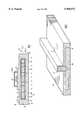
- FIG. 2is a perspective view of an alternate embodiment of a substrate for cooling an electronic component.
- FIG. 1is a cross-sectional view of an apparatus 10, such as a substrate, for cooling an electronic component 20 according to a preferred embodiment of the present invention.
- Substrate 10has a first side 12 and a second side 14.
- Electronic component 20is disposed on first side 12, and includes a base 17, a cover 21 and one or more silicon dice 22, which are protected by cover 21.
- Electronic component 20may be, for example, an NPN Silicon Radio Frequency (RF) Power Transistor such as a flangeless RF power transistor, and may be mounted directly to first side 12, or may be attached to a mounting plate (not shown), which is in turn secured to first side 12.
- RFNPN Silicon Radio Frequency
- References to electronic component 20will be understood to apply not only to component 20 as depicted and described in connection with FIG. 1, but also to completely different components, including but not limited to passive components, all types of integrated circuits, multi-chip modules and hybrid circuits.
- an insert material 16is surrounded by encapsulating material 18.
- Material 16is disposed proximate, preferably directly underneath, component 20.
- Material 16preferably has a first thermal conductivity K1 24 in a first direction 25, and a second thermal conductivity K2 26 in a second direction 27, the first and second directions being normal to each other.
- thermal conductivity K1 24is preferably substantially lower than second thermal conductivity K2 26.
- K1 24 and K2 26have substantially similar thermal conductivities.
- a suitable materialis a thermal pyrolytic graphite (TPG) material, commercially available from Advanced Ceramics Corporation in Lakewood, Ohio.
- Other suitable materialsinclude, but are not limited to diamond-like-carbon (DLC) and diamond.
- Encapsilating material 18preferably has a coefficient of thermal expansion similar to silicon dice 22, so that, among other things, dice 22 may be brazed or soldered or otherwise joined directly to material 18, if desired.
- An example of a suitable materialis aluminum silicon carbide (AlSiC).
- heat 25is removed from second side 14 of substrate 10 using advanced thermal management techniques including but not limited to cold plates or evaporative spray cooling. To achieve optimum design parameters (e.g., size, weight, flow rates, etc.) of such cooling systems, it is desirable to minimize temperature gradients present on cooled surfaces such as second side 14. Heat 25 may also be removed from top face 12, particularly when directly cooling electronic component 20.
- a number of selectively placed vias 30are formed in first direction 25 through insert material 16.
- Viasare preferably placed under or near heat-generating electronic components such as component 20.
- Vias 30allow for the channeling of heat in first direction 25, into the core of insert material 16, so that at a cooled side such as second side 14 or first side 12, a temperature gradient is preferably predictable, uniform and minimized. That is, vias 30 conduct heat in direction 25 in order to take advantage of the high thermal conductivity of the insert material 16, which spreads heat in direction 27.
- Vias 30may be filled with encapsulating material 18 or impregnated with aluminum 60 (discussed further below).
- Vias 30may be formed in any desired configuration, and each may have a cross-sectional shape which is conical, cylindrical, rectangular or another suitable shape. In addition, vias 30 may be configured in any manner effective to reduce stress concentrations or improve mechanical integrity of substrate 20.
- substrate 10includes a first portion 52 of insert material 16 and a second portion 54 of insert material 16 placed at an angle with respect to each other, such as a right angle. As shown, first and second portions 52, 54 are surrounded by encapsulating material 18.
- each portion 52, 54conducts heat differently in first and second directions 25, 27 respectively, so that first portion 52 as positioned has thermal conductivity K2 26 in first direction 25 and second portion 54 has thermal conductivity K2 26 in second direction 27.
- heat from die 22may be conducted in first direction 25 by first portion 52 and in second direction 27 by second portion 54.
- Such a configurationmay be useful for channeling heat away from die 22 when die 22 is disposed above first side 12 of substrate 10.
- Vias 30may also be used in connection with the configuration shown in FIG. 2.
- One method of manufacture of substrate 10includes placing insert material 16 having vias 30 formed therein into a mold (not shown), and injecting a silicon carbide slurry around insert material 16. The resulting preform is than infiltrated with aluminum to complete the process of creating an encapsulating AlSiC material. Because AlSiC contracts upon cooling more than insert material 16 such as TPG, a compression/interference fit may be created between encapsulating material 18 and insert material 16. During cooling, vias 30 also help to compress sides 12 and 14 toward insert material 16, so that a good thermal interface is formed between encapsulating material 18 and insert material 16.
- insert material 16may be disposed in a pre-manufactured silicon carbide preform (not shown). Liquid aluminum 60 may then be injected into the assembly formed by insert material 16 and the silicon carbide preform.
- vias 30further aid in conducting heat in first direction 25. Vias may also lend structural strength to substrate 10.
- a closed-loop liquid cooling system(not shown) for cooling substrate 10 may also be provided.
- a fluid pumpmay supply a coolant fluid such as water or a dielectric coolant to second side 14 of substrate 10.
- a heat exchangermay be connected to the fluid pump and may accept heated fluid, rejecting heat from the fluid and supplying cooled fluid to the fluid pump. It will be appreciated that at any given point the coolant may be a vapor, a liquid or a vapor and liquid mixture.
- any conventional means for providing flow of a coolantmay be used in conjunction with the described embodiments of the present invention, and that more than one apparatus or substrate may be connected to a single source of coolant or that one or more sources of coolant may be connected to a single apparatus, for example, for redundancy purposes.
- Sizes of fluid pumps and heat exchangersshould be selected based on heat removal and flow rate requirements. For example, a typical closed-loop fluid flow is 500 to 1000 milliliters per minute for 500 to 1000 Watts of heat dissipation. Pump and heat exchanger assemblies in various sizes, as well as acceptable tubings and fittings, are available from Cole-Parmer in Vernon Hills, Ill., as well as other common sources.
- An electronic component or a group of electronic componentsmay be effectively cooled using the disclosed substrates and methods. For a given heat load, heat transfer may be increased, fluid flow rates decreased and cooling system size reduced when a temperature gradient on second side 14 is minimized through the use of vias 30.
- the embodiments of the present inventionare not limited to cooling an electronic component, but may be adapted to cool any heat source, for example, a heat sink or flange which is mounted to a substrate in a traditional fashion.
- any heat sourcefor example, a heat sink or flange which is mounted to a substrate in a traditional fashion.
Landscapes
- Engineering & Computer Science (AREA)
- Microelectronics & Electronic Packaging (AREA)
- Chemical & Material Sciences (AREA)
- Materials Engineering (AREA)
- Physics & Mathematics (AREA)
- Condensed Matter Physics & Semiconductors (AREA)
- General Physics & Mathematics (AREA)
- Computer Hardware Design (AREA)
- Power Engineering (AREA)
- Cooling Or The Like Of Semiconductors Or Solid State Devices (AREA)
- Cooling Or The Like Of Electrical Apparatus (AREA)
Abstract
Description
Claims (11)
Priority Applications (4)
| Application Number | Priority Date | Filing Date | Title |
|---|---|---|---|
| US08/941,793US5958572A (en) | 1997-09-30 | 1997-09-30 | Hybrid substrate for cooling an electronic component |
| PCT/US1998/012365WO1999017596A1 (en) | 1997-09-30 | 1998-06-12 | Hybrid substrate for cooling an electronic component and method for forming the substrate |
| AU78390/98AAU7839098A (en) | 1997-09-30 | 1998-06-12 | Hybrid substrate for cooling an electronic component and method for forming the substrate |
| TW87110217ATW396561B (en) | 1997-09-30 | 1998-06-25 | Hybrid substrate for cooling an electronic component and method for forming the substrate |
Applications Claiming Priority (1)
| Application Number | Priority Date | Filing Date | Title |
|---|---|---|---|
| US08/941,793US5958572A (en) | 1997-09-30 | 1997-09-30 | Hybrid substrate for cooling an electronic component |
Publications (1)
| Publication Number | Publication Date |
|---|---|
| US5958572Atrue US5958572A (en) | 1999-09-28 |
Family
ID=25477071
Family Applications (1)
| Application Number | Title | Priority Date | Filing Date |
|---|---|---|---|
| US08/941,793Expired - LifetimeUS5958572A (en) | 1997-09-30 | 1997-09-30 | Hybrid substrate for cooling an electronic component |
Country Status (4)
| Country | Link |
|---|---|
| US (1) | US5958572A (en) |
| AU (1) | AU7839098A (en) |
| TW (1) | TW396561B (en) |
| WO (1) | WO1999017596A1 (en) |
Cited By (47)
| Publication number | Priority date | Publication date | Assignee | Title |
|---|---|---|---|---|
| US6075701A (en)* | 1999-05-14 | 2000-06-13 | Hughes Electronics Corporation | Electronic structure having an embedded pyrolytic graphite heat sink material |
| US6131651A (en)* | 1998-09-16 | 2000-10-17 | Advanced Ceramics Corporation | Flexible heat transfer device and method |
| US6257328B1 (en)* | 1997-10-14 | 2001-07-10 | Matsushita Electric Industrial Co., Ltd. | Thermal conductive unit and thermal connection structure using the same |
| US6407922B1 (en)* | 2000-09-29 | 2002-06-18 | Intel Corporation | Heat spreader, electronic package including the heat spreader, and methods of manufacturing the heat spreader |
| US20030116312A1 (en)* | 2001-12-13 | 2003-06-26 | Krassowski Daniel W. | Heat dissipating component using high conducting inserts |
| US20030196825A1 (en)* | 2002-04-17 | 2003-10-23 | Richard Adams | Metal matrix composite structure and method |
| US6661317B2 (en) | 2002-03-13 | 2003-12-09 | The Boeing Co. | Microwave monolithic integrated circuit assembly with multi-orientation pyrolytic graphite heat-dissipating assembly |
| US20050013119A1 (en)* | 2003-07-17 | 2005-01-20 | Sanjay Misra | Thermal diffusion apparatus |
| US20050064230A1 (en)* | 2003-09-19 | 2005-03-24 | General Electric Company | Bulk high thermal conductivity feedstock and method of making thereof |
| US20050077525A1 (en)* | 2003-10-09 | 2005-04-14 | Manuel Lynch | LED luminaire |
| US20050190553A1 (en)* | 2003-09-22 | 2005-09-01 | Manuel Lynch | Lighting apparatus |
| US20060000591A1 (en)* | 2002-04-17 | 2006-01-05 | Adams Richard W | Metal matrix composite structure and method |
| WO2004097934A3 (en)* | 2003-05-01 | 2006-01-05 | Queen Mary & Westfield College | An encased thermal management device and method of making such a device |
| US20060131010A1 (en)* | 2004-12-21 | 2006-06-22 | Chih-Ming Hsu | Heat dissipating assembly for a heat element |
| US20060261783A1 (en)* | 2005-05-23 | 2006-11-23 | Paul Gamboa | Electronic battery module (EBM) with bidirectional DC-DC converter |
| US20070041220A1 (en)* | 2005-05-13 | 2007-02-22 | Manuel Lynch | LED-based luminaire |
| US20070053168A1 (en)* | 2004-01-21 | 2007-03-08 | General Electric Company | Advanced heat sinks and thermal spreaders |
| US20070103875A1 (en)* | 2005-11-04 | 2007-05-10 | Reis Bradley E | Cycling LED Heat Spreader |
| US20070102142A1 (en)* | 2005-11-04 | 2007-05-10 | Reis Bradley E | Heat spreaders with vias |
| US20070139895A1 (en)* | 2005-11-04 | 2007-06-21 | Reis Bradley E | LED with integral thermal via |
| US20070231560A1 (en)* | 2005-10-11 | 2007-10-04 | General Electric Company | Thermal transport structure and associated method |
| US20070240310A1 (en)* | 2005-10-11 | 2007-10-18 | General Electric Company | Thermal management system and associated method |
| US20070257359A1 (en)* | 2006-05-03 | 2007-11-08 | Reis Bradley E | Thermal Management Device For A Memory Module |
| US20080019097A1 (en)* | 2005-10-11 | 2008-01-24 | General Electric Company | Thermal transport structure |
| US20080085403A1 (en)* | 2006-10-08 | 2008-04-10 | General Electric Company | Heat transfer composite, associated device and method |
| US20080128067A1 (en)* | 2006-10-08 | 2008-06-05 | Momentive Performance Materials Inc. | Heat transfer composite, associated device and method |
| US20080192462A1 (en)* | 2007-02-14 | 2008-08-14 | James Steedly | Strip illumination device |
| US20090032217A1 (en)* | 2007-07-31 | 2009-02-05 | Adc Telecommunications, Inc. | Apparatus for spreading heat over a finned surface |
| US20090032218A1 (en)* | 2007-07-31 | 2009-02-05 | Adc Telecommunications, Inc. | Apparatus for transferring between two heat conducting surfaces |
| US20090034204A1 (en)* | 2007-07-31 | 2009-02-05 | Adc Telecommunications, Inc. | Apparatus for transferring heat from a heat spreader |
| US20090032234A1 (en)* | 2007-07-31 | 2009-02-05 | Adc Telecommunications, Inc. | Apparatus for transferring heat in a fin of a heat sink |
| US20090141452A1 (en)* | 2007-11-30 | 2009-06-04 | Adc Telecommunications, Inc. | Apparatus for directing heat to a heat spreader |
| US20090168354A1 (en)* | 2007-12-26 | 2009-07-02 | Radesh Jewram | Thermally and electrically conductive interconnect structures |
| US20090185352A1 (en)* | 2008-01-17 | 2009-07-23 | Ellsworth Joseph R | High performance power device |
| US20100037934A1 (en)* | 2008-08-13 | 2010-02-18 | Sunplus Mmedia Inc. | Solar energy sysyem |
| US20100326645A1 (en)* | 2004-01-21 | 2010-12-30 | Wei Fan | Thermal pyrolytic graphite laminates with vias |
| US20110014417A1 (en)* | 2009-07-14 | 2011-01-20 | Lemak Richard J | Anisotropic thermal conduction element and manufacturing method |
| US7889502B1 (en) | 2005-11-04 | 2011-02-15 | Graftech International Holdings Inc. | Heat spreading circuit assembly |
| US20120118549A1 (en)* | 2010-11-12 | 2012-05-17 | Toyota Motor Engineering & Manufacturing North America, Inc. | Heat Conducting Composite Materials, Systems and Methods For Manufacturing The Same |
| WO2014052282A1 (en) | 2012-09-25 | 2014-04-03 | Momentive Performance Materials Inc. | Thermal management assembly comprising bulk graphene material |
| US20160095201A1 (en)* | 2014-09-30 | 2016-03-31 | Samsung Electro-Mechanics Co., Ltd. | Circuit board comprising heat transfer structure |
| US20170251548A1 (en)* | 2015-02-23 | 2017-08-31 | Samsung Electro-Mechanics Co., Ltd. | Circuit board and manufacturing method thereof |
| US20180112938A1 (en)* | 2016-10-26 | 2018-04-26 | Goodrich Aerospace Services Private Limited | Die-cast bodies with thermal conductive inserts |
| US10090222B2 (en)* | 2017-02-17 | 2018-10-02 | Fuji Electric Co., Ltd. | Semiconductor device with heat dissipation and method of making same |
| US10347559B2 (en) | 2011-03-16 | 2019-07-09 | Momentive Performance Materials Inc. | High thermal conductivity/low coefficient of thermal expansion composites |
| US11049795B2 (en)* | 2017-01-31 | 2021-06-29 | Supergrid Institute | Electronic power module comprising a dielectric support |
| US11570882B2 (en)* | 2018-03-28 | 2023-01-31 | Kyocera Corporation | Substrate for mounting electronic element, electronic device, and electronic module |
Citations (1)
| Publication number | Priority date | Publication date | Assignee | Title |
|---|---|---|---|---|
| US5296310A (en)* | 1992-02-14 | 1994-03-22 | Materials Science Corporation | High conductivity hydrid material for thermal management |
- 1997
- 1997-09-30USUS08/941,793patent/US5958572A/ennot_activeExpired - Lifetime
- 1998
- 1998-06-12AUAU78390/98Apatent/AU7839098A/ennot_activeAbandoned
- 1998-06-12WOPCT/US1998/012365patent/WO1999017596A1/enactiveApplication Filing
- 1998-06-25TWTW87110217Apatent/TW396561B/ennot_activeIP Right Cessation
Patent Citations (1)
| Publication number | Priority date | Publication date | Assignee | Title |
|---|---|---|---|---|
| US5296310A (en)* | 1992-02-14 | 1994-03-22 | Materials Science Corporation | High conductivity hydrid material for thermal management |
Non-Patent Citations (7)
| Title |
|---|
| ClimaxClad Copper Molybdenum Copper product brochure, Climax Specialty Materials, Cleveland, Ohio. Jan. 1990.* |
| ClimaxClad Copper-Molybdenum-Copper product brochure, Climax Specialty Materials, Cleveland, Ohio. Jan. 1990. |
| Preliminary Product Data for "High Thermal Conductivity Black-Ice ™ Substrate Materials", Applied Sciences, Inc., Cedarville, Ohio Jan. 1995. |
| Preliminary Product Data for High Thermal Conductivity Black Ice Substrate Materials , Applied Sciences, Inc., Cedarville, Ohio Jan. 1995.* |
| Product Description Documents by Advanced Ceramics Corp. for the following products: TC1050 Encapsulated TPG; TC1050.ALY Aluminum Encapsulated TPG; TC1050.CFC Carbon FIber Composite encapsulated TPG; TC1050.KOV Kovar Encapsulated TPG; TC1050.CO Copper Encapsulated TPG; TC1050.MMC A1SiC Encapsulated TPG/ Jan. 1995.* |
| Product Overview Document for "TC1050 Thermal Management Material System" by Advanced Ceramics Corp. Dec., 1994. |
| Product Overview Document for TC1050 Thermal Management Material System by Advanced Ceramics Corp. Dec., 1994.* |
Cited By (88)
| Publication number | Priority date | Publication date | Assignee | Title |
|---|---|---|---|---|
| US6257328B1 (en)* | 1997-10-14 | 2001-07-10 | Matsushita Electric Industrial Co., Ltd. | Thermal conductive unit and thermal connection structure using the same |
| US6131651A (en)* | 1998-09-16 | 2000-10-17 | Advanced Ceramics Corporation | Flexible heat transfer device and method |
| US6075701A (en)* | 1999-05-14 | 2000-06-13 | Hughes Electronics Corporation | Electronic structure having an embedded pyrolytic graphite heat sink material |
| US6407922B1 (en)* | 2000-09-29 | 2002-06-18 | Intel Corporation | Heat spreader, electronic package including the heat spreader, and methods of manufacturing the heat spreader |
| US20030116312A1 (en)* | 2001-12-13 | 2003-06-26 | Krassowski Daniel W. | Heat dissipating component using high conducting inserts |
| US6758263B2 (en)* | 2001-12-13 | 2004-07-06 | Advanced Energy Technology Inc. | Heat dissipating component using high conducting inserts |
| US6661317B2 (en) | 2002-03-13 | 2003-12-09 | The Boeing Co. | Microwave monolithic integrated circuit assembly with multi-orientation pyrolytic graphite heat-dissipating assembly |
| WO2003079435A3 (en)* | 2002-03-13 | 2004-05-06 | Boeing Co | Microwave monolithic integrated circuit assembly with multi-orientation pyrolytic graphite heat-dissipating assembly |
| US20030196825A1 (en)* | 2002-04-17 | 2003-10-23 | Richard Adams | Metal matrix composite structure and method |
| US20060000591A1 (en)* | 2002-04-17 | 2006-01-05 | Adams Richard W | Metal matrix composite structure and method |
| US7141310B2 (en)* | 2002-04-17 | 2006-11-28 | Ceramics Process Systems Corporation | Metal matrix composite structure and method |
| US6884522B2 (en) | 2002-04-17 | 2005-04-26 | Ceramics Process Systems Corp. | Metal matrix composite structure and method |
| US20070090519A1 (en)* | 2003-05-01 | 2007-04-26 | Carter Antony A | Encased thermal management device and method of making such a device |
| WO2004097934A3 (en)* | 2003-05-01 | 2006-01-05 | Queen Mary & Westfield College | An encased thermal management device and method of making such a device |
| WO2005010452A3 (en)* | 2003-07-17 | 2005-12-08 | Bergquist Co | Thermal diffusion apparatus |
| US6898084B2 (en)* | 2003-07-17 | 2005-05-24 | The Bergquist Company | Thermal diffusion apparatus |
| US20050013119A1 (en)* | 2003-07-17 | 2005-01-20 | Sanjay Misra | Thermal diffusion apparatus |
| US20050064230A1 (en)* | 2003-09-19 | 2005-03-24 | General Electric Company | Bulk high thermal conductivity feedstock and method of making thereof |
| US7220485B2 (en) | 2003-09-19 | 2007-05-22 | Momentive Performance Materials Inc. | Bulk high thermal conductivity feedstock and method of making thereof |
| DE112004001018B4 (en)* | 2003-09-19 | 2016-12-29 | General Electric Co. | Coated pyrolytic graphite based feedstock, method of making same, method of forming thermal pyrolytic graphite tiles, and industrial articles |
| WO2005029931A1 (en)* | 2003-09-19 | 2005-03-31 | General Electric Company | Bulk high thermal conductivity feedstock and method of making thereof |
| US7329024B2 (en) | 2003-09-22 | 2008-02-12 | Permlight Products, Inc. | Lighting apparatus |
| US20080055915A1 (en)* | 2003-09-22 | 2008-03-06 | Permlight Products, Inc. | Lighting apparatus |
| US20050190553A1 (en)* | 2003-09-22 | 2005-09-01 | Manuel Lynch | Lighting apparatus |
| US8079731B2 (en) | 2003-09-22 | 2011-12-20 | Permlight Products, Inc. | Lighting apparatus |
| US7939837B2 (en) | 2003-10-09 | 2011-05-10 | Permlight Products, Inc. | LED luminaire |
| US20060267028A1 (en)* | 2003-10-09 | 2006-11-30 | Manuel Lynch | LED luminaire |
| US7102172B2 (en) | 2003-10-09 | 2006-09-05 | Permlight Products, Inc. | LED luminaire |
| US7582911B2 (en) | 2003-10-09 | 2009-09-01 | Permlight Products, Inc. | LED luminaire |
| US20090086488A1 (en)* | 2003-10-09 | 2009-04-02 | Permlight Products, Inc. | LED luminaire |
| US20050077525A1 (en)* | 2003-10-09 | 2005-04-14 | Manuel Lynch | LED luminaire |
| US20070053168A1 (en)* | 2004-01-21 | 2007-03-08 | General Electric Company | Advanced heat sinks and thermal spreaders |
| US20100326645A1 (en)* | 2004-01-21 | 2010-12-30 | Wei Fan | Thermal pyrolytic graphite laminates with vias |
| US20060131010A1 (en)* | 2004-12-21 | 2006-06-22 | Chih-Ming Hsu | Heat dissipating assembly for a heat element |
| US7918591B2 (en) | 2005-05-13 | 2011-04-05 | Permlight Products, Inc. | LED-based luminaire |
| US20070041220A1 (en)* | 2005-05-13 | 2007-02-22 | Manuel Lynch | LED-based luminaire |
| US20080042617A1 (en)* | 2005-05-23 | 2008-02-21 | Cobasys, Llc | Electronic battery module (EBM) with bidirectional DC-DC converter |
| US7649336B2 (en) | 2005-05-23 | 2010-01-19 | Cobasys, Llc | Power supply with bidirectional DC-DC converter |
| US20060261783A1 (en)* | 2005-05-23 | 2006-11-23 | Paul Gamboa | Electronic battery module (EBM) with bidirectional DC-DC converter |
| US20080019097A1 (en)* | 2005-10-11 | 2008-01-24 | General Electric Company | Thermal transport structure |
| US7297399B2 (en) | 2005-10-11 | 2007-11-20 | General Electric Company | Thermal transport structure and associated method |
| US7797808B2 (en) | 2005-10-11 | 2010-09-21 | General Electric Company | Thermal management system and associated method |
| US20070231560A1 (en)* | 2005-10-11 | 2007-10-04 | General Electric Company | Thermal transport structure and associated method |
| US20070240310A1 (en)* | 2005-10-11 | 2007-10-18 | General Electric Company | Thermal management system and associated method |
| US20070139895A1 (en)* | 2005-11-04 | 2007-06-21 | Reis Bradley E | LED with integral thermal via |
| US20070103875A1 (en)* | 2005-11-04 | 2007-05-10 | Reis Bradley E | Cycling LED Heat Spreader |
| US20070102142A1 (en)* | 2005-11-04 | 2007-05-10 | Reis Bradley E | Heat spreaders with vias |
| US7889502B1 (en) | 2005-11-04 | 2011-02-15 | Graftech International Holdings Inc. | Heat spreading circuit assembly |
| US7505275B2 (en) | 2005-11-04 | 2009-03-17 | Graftech International Holdings Inc. | LED with integral via |
| US7365988B2 (en) | 2005-11-04 | 2008-04-29 | Graftech International Holdings Inc. | Cycling LED heat spreader |
| US7303005B2 (en) | 2005-11-04 | 2007-12-04 | Graftech International Holdings Inc. | Heat spreaders with vias |
| US7573717B2 (en) | 2005-11-04 | 2009-08-11 | Graftech International Holdings Inc. | Cycling LED heat spreader |
| US20070257359A1 (en)* | 2006-05-03 | 2007-11-08 | Reis Bradley E | Thermal Management Device For A Memory Module |
| US20080128067A1 (en)* | 2006-10-08 | 2008-06-05 | Momentive Performance Materials Inc. | Heat transfer composite, associated device and method |
| US20080085403A1 (en)* | 2006-10-08 | 2008-04-10 | General Electric Company | Heat transfer composite, associated device and method |
| US7815341B2 (en) | 2007-02-14 | 2010-10-19 | Permlight Products, Inc. | Strip illumination device |
| US20080192462A1 (en)* | 2007-02-14 | 2008-08-14 | James Steedly | Strip illumination device |
| US20090034204A1 (en)* | 2007-07-31 | 2009-02-05 | Adc Telecommunications, Inc. | Apparatus for transferring heat from a heat spreader |
| US8235094B2 (en) | 2007-07-31 | 2012-08-07 | Adc Telecommunications, Inc. | Apparatus for transferring heat in a fin of a heat sink |
| US20090032217A1 (en)* | 2007-07-31 | 2009-02-05 | Adc Telecommunications, Inc. | Apparatus for spreading heat over a finned surface |
| US8051896B2 (en) | 2007-07-31 | 2011-11-08 | Adc Telecommunications, Inc. | Apparatus for spreading heat over a finned surface |
| US7539019B2 (en) | 2007-07-31 | 2009-05-26 | Adc Telecommunications, Inc. | Apparatus for transferring heat from a heat spreader |
| US20090032218A1 (en)* | 2007-07-31 | 2009-02-05 | Adc Telecommunications, Inc. | Apparatus for transferring between two heat conducting surfaces |
| US20090032234A1 (en)* | 2007-07-31 | 2009-02-05 | Adc Telecommunications, Inc. | Apparatus for transferring heat in a fin of a heat sink |
| US7672134B2 (en) | 2007-11-30 | 2010-03-02 | Adc Telecommunications, Inc. | Apparatus for directing heat to a heat spreader |
| US20090141452A1 (en)* | 2007-11-30 | 2009-06-04 | Adc Telecommunications, Inc. | Apparatus for directing heat to a heat spreader |
| US7760507B2 (en) | 2007-12-26 | 2010-07-20 | The Bergquist Company | Thermally and electrically conductive interconnect structures |
| US20090168354A1 (en)* | 2007-12-26 | 2009-07-02 | Radesh Jewram | Thermally and electrically conductive interconnect structures |
| US7742307B2 (en)* | 2008-01-17 | 2010-06-22 | Raytheon Company | High performance power device |
| US20090185352A1 (en)* | 2008-01-17 | 2009-07-23 | Ellsworth Joseph R | High performance power device |
| US8097803B2 (en)* | 2008-08-13 | 2012-01-17 | Sunplus Mmedia Inc. | Solar energy system |
| US20100037934A1 (en)* | 2008-08-13 | 2010-02-18 | Sunplus Mmedia Inc. | Solar energy sysyem |
| US20110014417A1 (en)* | 2009-07-14 | 2011-01-20 | Lemak Richard J | Anisotropic thermal conduction element and manufacturing method |
| US8085531B2 (en)* | 2009-07-14 | 2011-12-27 | Specialty Minerals (Michigan) Inc. | Anisotropic thermal conduction element and manufacturing method |
| US20120118549A1 (en)* | 2010-11-12 | 2012-05-17 | Toyota Motor Engineering & Manufacturing North America, Inc. | Heat Conducting Composite Materials, Systems and Methods For Manufacturing The Same |
| US9417013B2 (en)* | 2010-11-12 | 2016-08-16 | Toyota Motor Engineering & Manufacturing North America, Inc. | Heat transfer systems including heat conducting composite materials |
| US10347559B2 (en) | 2011-03-16 | 2019-07-09 | Momentive Performance Materials Inc. | High thermal conductivity/low coefficient of thermal expansion composites |
| WO2014052282A1 (en) | 2012-09-25 | 2014-04-03 | Momentive Performance Materials Inc. | Thermal management assembly comprising bulk graphene material |
| US11105567B2 (en) | 2012-09-25 | 2021-08-31 | Momentive Performance Materials Quartz, Inc. | Thermal management assembly comprising bulk graphene material |
| US20160095201A1 (en)* | 2014-09-30 | 2016-03-31 | Samsung Electro-Mechanics Co., Ltd. | Circuit board comprising heat transfer structure |
| US10015877B2 (en)* | 2014-09-30 | 2018-07-03 | Samsung Electro-Mechanics Co., Ltd. | Circuit board comprising heat transfer structure |
| US20170251548A1 (en)* | 2015-02-23 | 2017-08-31 | Samsung Electro-Mechanics Co., Ltd. | Circuit board and manufacturing method thereof |
| US10362667B2 (en)* | 2015-02-23 | 2019-07-23 | Samsung Electro-Mechanics Co., Ltd. | Circuit board and manufacturing method thereof |
| US20180112938A1 (en)* | 2016-10-26 | 2018-04-26 | Goodrich Aerospace Services Private Limited | Die-cast bodies with thermal conductive inserts |
| US11049795B2 (en)* | 2017-01-31 | 2021-06-29 | Supergrid Institute | Electronic power module comprising a dielectric support |
| US10090222B2 (en)* | 2017-02-17 | 2018-10-02 | Fuji Electric Co., Ltd. | Semiconductor device with heat dissipation and method of making same |
| US11570882B2 (en)* | 2018-03-28 | 2023-01-31 | Kyocera Corporation | Substrate for mounting electronic element, electronic device, and electronic module |
| US12193145B2 (en) | 2018-03-28 | 2025-01-07 | Kyocera Corporation | Substrate for mounting electronic element, electronic device, and electronic module preliminary class |
Also Published As
| Publication number | Publication date |
|---|---|
| TW396561B (en) | 2000-07-01 |
| WO1999017596A1 (en) | 1999-04-08 |
| AU7839098A (en) | 1999-04-23 |
Similar Documents
| Publication | Publication Date | Title |
|---|---|---|
| US5958572A (en) | Hybrid substrate for cooling an electronic component | |
| US8929071B2 (en) | Low cost manufacturing of micro-channel heatsink | |
| US6462410B1 (en) | Integrated circuit component temperature gradient reducer | |
| JP5801996B2 (en) | Double-sided cooling power module with power coating | |
| US7992627B2 (en) | Microjet module assembly | |
| JP5414349B2 (en) | Electronic equipment | |
| US8115302B2 (en) | Electronic module with carrier substrates, multiple integrated circuit (IC) chips and microchannel cooling device | |
| EP1628515B1 (en) | Integrated cooling system for electronic devices | |
| US7683479B2 (en) | Semiconductor package involving a rotary lock that connects a package substrate and a separate component | |
| US4860444A (en) | Method of assembling a fluid-cooled integrated circuit package | |
| JP6050617B2 (en) | Cooling device for power supply module and related method | |
| EP1294022B1 (en) | Electronic module including a cooling substrate having a fluid cooling circuit therein and related methods | |
| JPH0334229B2 (en) | ||
| US20070204972A1 (en) | Method and apparatus for dissipating heat | |
| EP3850662B1 (en) | Module base with integrated thermal spreader and heat sink for thermal and structural management of high-performance integrated circuits or other devices | |
| US12068223B2 (en) | Method of constructing a circuitry assembly for heat dispersal using a phase change material | |
| KR20190136915A (en) | Electronics cold plate | |
| US5937937A (en) | Heat sink and method for removing heat from a plurality of components | |
| US20060266496A1 (en) | Method and apparatus for dissipating heat | |
| WO1999006782A1 (en) | Apparatus and method for cooling an electronic component using a porous material | |
| JPH05315489A (en) | Liquid cooling system for electronic devices | |
| JPH03209859A (en) | Semiconductor cooling device | |
| EP1726197A2 (en) | An element for carrying electronic components | |
| JPH11168163A (en) | Electronic circuit package cooling device | |
| JPH08200911A (en) | Cooler for electric vehicle |
Legal Events
| Date | Code | Title | Description |
|---|---|---|---|
| AS | Assignment | Owner name:MOTOROLA, INC., ILLINOIS Free format text:ASSIGNMENT OF ASSIGNORS INTEREST;ASSIGNORS:SCHMIDT, DETLEF;PAIS, MARTIN R.;REEL/FRAME:008742/0679 Effective date:19970930 | |
| STCF | Information on status: patent grant | Free format text:PATENTED CASE | |
| FPAY | Fee payment | Year of fee payment:4 | |
| FPAY | Fee payment | Year of fee payment:8 | |
| AS | Assignment | Owner name:MOTOROLA MOBILITY, INC, ILLINOIS Free format text:ASSIGNMENT OF ASSIGNORS INTEREST;ASSIGNOR:MOTOROLA, INC;REEL/FRAME:025673/0558 Effective date:20100731 | |
| FPAY | Fee payment | Year of fee payment:12 | |
| AS | Assignment | Owner name:MOTOROLA MOBILITY LLC, ILLINOIS Free format text:CHANGE OF NAME;ASSIGNOR:MOTOROLA MOBILITY, INC.;REEL/FRAME:029216/0282 Effective date:20120622 | |
| AS | Assignment | Owner name:GOOGLE TECHNOLOGY HOLDINGS LLC, CALIFORNIA Free format text:ASSIGNMENT OF ASSIGNORS INTEREST;ASSIGNOR:MOTOROLA MOBILITY LLC;REEL/FRAME:034304/0001 Effective date:20141028 |