US5958081A - Energy efficient remote control protocol with improved reliability - Google Patents
Energy efficient remote control protocol with improved reliabilityDownload PDFInfo
- Publication number
- US5958081A US5958081AUS08/541,092US54109295AUS5958081AUS 5958081 AUS5958081 AUS 5958081AUS 54109295 AUS54109295 AUS 54109295AUS 5958081 AUS5958081 AUS 5958081A
- Authority
- US
- United States
- Prior art keywords
- code
- parity
- remote control
- segments
- transmission
- Prior art date
- Legal status (The legal status is an assumption and is not a legal conclusion. Google has not performed a legal analysis and makes no representation as to the accuracy of the status listed.)
- Expired - Fee Related
Links
Images


Classifications
- G—PHYSICS
- G08—SIGNALLING
- G08C—TRANSMISSION SYSTEMS FOR MEASURED VALUES, CONTROL OR SIMILAR SIGNALS
- G08C19/00—Electric signal transmission systems
- G08C19/16—Electric signal transmission systems in which transmission is by pulses
- G08C19/24—Electric signal transmission systems in which transmission is by pulses using time shift of pulses
- H—ELECTRICITY
- H04—ELECTRIC COMMUNICATION TECHNIQUE
- H04B—TRANSMISSION
- H04B14/00—Transmission systems not characterised by the medium used for transmission
- H04B14/02—Transmission systems not characterised by the medium used for transmission characterised by the use of pulse modulation
- H04B14/026—Transmission systems not characterised by the medium used for transmission characterised by the use of pulse modulation using pulse time characteristics modulation, e.g. width, position, interval
- H—ELECTRICITY
- H04—ELECTRIC COMMUNICATION TECHNIQUE
- H04L—TRANSMISSION OF DIGITAL INFORMATION, e.g. TELEGRAPHIC COMMUNICATION
- H04L1/00—Arrangements for detecting or preventing errors in the information received
- H04L1/004—Arrangements for detecting or preventing errors in the information received by using forward error control
Definitions
- the inventionrelates generally to a transmission protocol for remote control systems, and more particularly, to a transmission protocol for vehicle applications that is energy efficient and has high reliability.
- remote control transmittersfor activating anti-theft systems and remote entry systems in automotive vehicles are increasing.
- the remote control transmittersare generally battery operated and emit a coded signal for enabling and disabling particular functions.
- the transmissionmust be energy efficient since it is desirable to extend the battery life of the transmitter.
- remote control systemsAnother desirable attribute in remote control systems is reliable system performance. With increasing implementation of remote control systems, it is increasingly desirable to have the remote control system distinguish between transmissions for its associated transmitter and transmissions from other transmitters. Such a problem occurs when two similar systems transmit simultaneously. When two or more systems transmit simultaneously, the receiver may interpret the transmission as an actual transmission rather than recognizing it as an erroneous transmission.
- One advantage of the inventionis that the energy assumed and transmitting at a data packet is significantly reduced due to the use of only one socket per data packet rather than per bit.
- the present inventionincludes a transmitter generating a transmission of a code.
- the codehas a plurality of bits.
- the transmittergroups the bits into a plurality of groups, each of the groups having a parity and a numeric value.
- the transmissionhas a plurality of segments corresponding to each of the groups. Each of the segments has a start bit length corresponding to the parity of the group and a data length corresponding to the numeric value of the group.
- a receiveris connected to a memory and receives the transmission and converts the transmission into a received code based on the data length of each of the segments. The receiver compares the code to a stored code in the memory and enables a function if said received code matches said stored code.
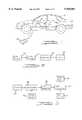
- FIG. 1is a diagrammatic view of an automobile having a remote control system according to the present invention.
- FIG. 2is a block diagram of the transmitter according to the present invention.
- FIG. 3is a block diagram of a receiver according to the present invention.
- FIGS. 4A-4Iis a 48-bit data code according to the present invention.
- FIG. 5is a transmission of a 48-bit data code of FIG. 4.
- FIGS. 6A and 6Bare two transmissions according to a prior art protocol.
- FIG. 6Cis a combination of the transmissions of FIGS. 6A and 6B.
- FIGS. 7A and 7Bare transmissions using the protocol of the present invention.
- FIG. 7Cis a combination of the transmissions of FIG. 7A and 7B.
- an automobile 10has a remote control system that enables or disables a function upon receipt of a valid security code.
- Remote control systems with a receiver 12are used to disarm an automobile anti-theft system to unlock a door latch 14 upon receipt of a valid code.
- a transmitter 16is used to transmit the coded signal to receiver 12.
- the coded signal of the present inventionis preferably an RF signal. However, various transmission methods may be used, such as infrared or transmission through wire.
- the coded signalhas a start bit and a data code portion. To conserve energy, the data code portion preferably is a low logic level signal, i.e., dead time where the duration of the dead time represents the data.
- transmitter 16has a code register 18, a parity encoder 20, a modulator 22, and an emitter 24.
- Code register 18is used to store the code information which is typically in hexadecimal form.
- Code register 18converts the hexadecimal digits to binary, i.e., four binary bits.
- Code register 18groups the bits for binary transmission, e.g., a group of six bits is used in this example.
- Parity encoder 20is used to determine the parity of the groups of bits from code register 18. Parity is the number of ones in a binary data packet. The parity information is used to determine the length of the start bit. A different time duration is assigned to an odd or even parity. For example, if the code in the code register is even, then the length of the start bit is 0.5 milliseconds and if the code in the code register is odd then the length of the start bit is 0.7 milliseconds.
- Modulator 22converts the information from code register 18 and parity encoder 20 into segments to be transmitted.
- the segmentshave a start bit, guard time and data information for each group of bits.
- the start bitis preferably a high logic level.
- the data information and guard timeare a low logic level whose data length represents the actual data information.
- the guard timeis further described below and is used as a check on the transmitted signal.
- the information from code register 18 and parity encoder 20is then modulated into a modulated signal.
- Emitter 24receives the modulated data from modulator 22 and transmits the information.
- an RF transmissionis used.
- receiver 12has a detector 26, a demodulator 28, timing control 30, an error detector 32, a code comparator 34, a code register 36, and an output driver 38.
- Detector 26is used to detect the transmitted code segments from the transmitter 16.
- Demodulator 28receives the pulses from detector 26 and separates the transmission into segments. Timing control 30 measures the time of the start pulses and dead time between the pulses received by demodulator 28. Error detector 32 determines whether there has been an error in the transmission of the signal or the reception of the signal. The operation of error detection 32 will become evident in conjunction with FIGS. 4 and 7. Error detector provides an indication of an error by generating an error signal to provide feedback to a system controller or to an indicator such as an audible warning or visual warning like an indicator light.
- Code comparator 34compares a code stored in code register 36 with a received code. If the code in code register 36 and the received code are the same, then output driver 38 enables, for example, an unlock feature for the vehicle.
- Code 36is a memory device.
- FIG. 4Ais an example of a hexadecimal data code for a 48 bit data code to be transmitted.
- FIG. 4Bthe hex data code of FIG. 4A is converted in code register 18 into a binary data packet.
- the binary datais shown directly below that of FIG. 4A.
- the 4-bit datais regrouped in code register 18 into 6-bit groupings, which are shown directly below that of their corresponding bits of FIG. 4B.
- FIG. 4Dthe decimal equivalent of the 6-bit regrouping is shown.
- FIG. 4Ethe parity of the 6-bit group is shown for each of the 6-bit symbols directly below their associated symbols.
- FIG. 4Fthe duration of start pulse of each data packet is shown.
- the start pulse lengthcorresponds to the parity of the 6-bit regrouping.
- the start pulse for odd parityis 0.7 milliseconds, and the start pulse for an even parity is 0.5 milliseconds.
- the duration of the guard timeis shown for each associated data packet.
- the guard timeis preferably constant for each grouping. In this case the guard time is a constant 0.5 milliseconds.
- the duration of data dead time for each 6 bit regrouped packetis shown below its associated 6-bit regroup packet.
- the dead time associated with each symbolis the decimal equivalent of the grouping multiplied by 0.1 milliseconds.
- the multipliermay be any convenient value.
- the decimal equivalent of the symbolis 7, which corresponds to 0.7 milliseconds.
- the decimal equivalent of the second symbolis 50, which corresponds to 5 milliseconds.
- the decimal equivalentis 19, which corresponds to 1.9 milliseconds, and so forth.
- the guard timeis part of the dead time, which is a constant 0.5 milliseconds.
- the total dead time associated with each data packetis shown.
- the first data grouphas 0.5 milliseconds dead time associated with the guard time and 0.7 milliseconds of dead time associated with the data group for a total dead time of 1.2 milliseconds.
- the dead time associated with the symbolis 5 milliseconds plus a guard time of 0.5 milliseconds for a total dead time of 5.5 milliseconds, and so on.
- portion Ais a start bit of 0.7 milliseconds in duration since the parity of the first symbol is odd.
- the dead time associated with the symbolis 0.7 milliseconds plus the guard time of 0.5 milliseconds, a total dead time of portion B of 1.2 milliseconds.
- the parityis odd so the start pulse width is 0.7 milliseconds.
- the total dead timeis 5.5 milliseconds.
- the guard timeis 0.5 milliseconds, and the data time is 5 milliseconds.
- portion Ethe parity of the symbol is again odd so the start bit is 0.7 milliseconds.
- the dead timeis a total of 2.4 milliseconds, 1.9 milliseconds of which corresponds to the data.
- the parityis even, thus the start bit is thus 0.5 milliseconds.
- the total dead timeis 3.5 milliseconds, which corresponds to a data time of 3 milliseconds.
- portion Iis a stop bit, which is used only at the very end of the 48-bit data packet, and may be assigned a unique width to clearly indicate the end of the packet transmission.
- FIGS. 6A and 6Btwo transmissions are shown using the data and coding scheme of U.S. Pat. No. 5,349,459, as described in the Background Of The Invention.
- FIG. 6Cthe data of two simultaneous transmissions is added together and received as one signal.
- the signal of FIG. 6Cif decoded according to the '459 patent would be interpreted as a valid coded signal. Thus, a wrong code would be received by the transmitter and the lock or other associated function would not be enabled. No indication of a corrupt signal would be given by the receiver. Further, two wrong codes may combine to form a proper code to enable the system.
- FIGS. 7A and 7Btwo transmissions using the present invention are shown. Each of the transmissions has a start time, a guard time, and data time.
- FIG. 7Cthe two transmissions would be simultaneously received. However, according to the present invention, these transmissions would be determined to be corrupt data. The corrupt data would therefore not be able to enable or disable a function. The decoding circuitry would, however, be able to interpret this as corrupt data.
- portion Hwhich is 0.7 milliseconds long, this indicates that the parity of the data should be odd parity.
- Portion Iis the guard time which is always 0.5 milliseconds.
- Portion Jis 1.0 milliseconds, which corresponds to a coded symbol of 10 which the 6-bit grouping of which in binary is 001010. For this grouping, counting the number of 1's the parity is even. Since the receiver is expected to receive an odd parity, the received code fails the parity check. Thus, the transmission will be rejected. Looking at signal portions K-M, portion K is 0.7 milliseconds, which corresponds to an odd parity, but portion L is smaller than 0.5 milliseconds, so the guard time of 0.5 milliseconds has been violated, which also signals that the transmission received is corrupt.
Landscapes
- Engineering & Computer Science (AREA)
- Computer Networks & Wireless Communication (AREA)
- Signal Processing (AREA)
- Physics & Mathematics (AREA)
- General Physics & Mathematics (AREA)
- Selective Calling Equipment (AREA)
Abstract
Description
Claims (16)
Priority Applications (4)
| Application Number | Priority Date | Filing Date | Title |
|---|---|---|---|
| US08/541,092US5958081A (en) | 1995-10-11 | 1995-10-11 | Energy efficient remote control protocol with improved reliability |
| JP8267407AJPH09130868A (en) | 1995-10-11 | 1996-10-08 | Remote control system |
| DE69617162TDE69617162T2 (en) | 1995-10-11 | 1996-10-09 | Remote control system |
| EP96307343AEP0768631B1 (en) | 1995-10-11 | 1996-10-09 | A remote control system |
Applications Claiming Priority (1)
| Application Number | Priority Date | Filing Date | Title |
|---|---|---|---|
| US08/541,092US5958081A (en) | 1995-10-11 | 1995-10-11 | Energy efficient remote control protocol with improved reliability |
Publications (1)
| Publication Number | Publication Date |
|---|---|
| US5958081Atrue US5958081A (en) | 1999-09-28 |
Family
ID=24158145
Family Applications (1)
| Application Number | Title | Priority Date | Filing Date |
|---|---|---|---|
| US08/541,092Expired - Fee RelatedUS5958081A (en) | 1995-10-11 | 1995-10-11 | Energy efficient remote control protocol with improved reliability |
Country Status (4)
| Country | Link |
|---|---|
| US (1) | US5958081A (en) |
| EP (1) | EP0768631B1 (en) |
| JP (1) | JPH09130868A (en) |
| DE (1) | DE69617162T2 (en) |
Cited By (5)
| Publication number | Priority date | Publication date | Assignee | Title |
|---|---|---|---|---|
| US6384710B1 (en)* | 1998-04-06 | 2002-05-07 | Trw Inc. | Apparatus and method for remote convenience message reception and control utilizing frequency diversity |
| US20040095229A1 (en)* | 2002-11-08 | 2004-05-20 | E-Lead Electronic Co., Ltd. | Anti-theft and two-way communication apparatus for vehicles |
| US20050104755A1 (en)* | 2003-11-17 | 2005-05-19 | Tsang Kinhing P. | System for encoding and transmitting data |
| US7054361B1 (en) | 2000-05-31 | 2006-05-30 | Thomson Licensing | Method and apparatus for enhancing an infrared signal protocol |
| US20080203815A1 (en)* | 2002-12-26 | 2008-08-28 | Takao Ozawa | Vehicle Antitheft Device and Control Method of a Vehicle |
Families Citing this family (2)
| Publication number | Priority date | Publication date | Assignee | Title |
|---|---|---|---|---|
| JP2004201098A (en)* | 2002-12-19 | 2004-07-15 | Matsushita Electric Ind Co Ltd | Electronic equipment and wireless remote control |
| DE102008006751A1 (en)* | 2008-01-30 | 2009-08-27 | Siemens Aktiengesellschaft | Remote control e.g. remote control key for car, operating method, involves signaling feedbacks by remote control to user, where feedbacks indicate commands that are not transmitted and/or executed |
Citations (14)
| Publication number | Priority date | Publication date | Assignee | Title |
|---|---|---|---|---|
| US4186345A (en)* | 1976-11-05 | 1980-01-29 | Sony Corporation | Remote control system |
| US4251812A (en)* | 1977-10-27 | 1981-02-17 | Sony Corporation | Remote control system |
| US4377862A (en)* | 1978-12-06 | 1983-03-22 | The Boeing Company | Method of error control in asynchronous communications |
| EP0102815A2 (en)* | 1982-09-02 | 1984-03-14 | BRITISH TELECOMMUNICATIONS public limited company | Optical communication |
| US4459591A (en)* | 1981-02-05 | 1984-07-10 | Robert Bosch Gmbh | Remote-control operating system and method for selectively addressing code-addressable receivers, particularly to execute switching function in automotive vehicles |
| US4555702A (en)* | 1981-09-17 | 1985-11-26 | Hitachi, Ltd. | Remote control signal reproducing circuit |
| US4612640A (en)* | 1984-02-21 | 1986-09-16 | Seeq Technology, Inc. | Error checking and correction circuitry for use with an electrically-programmable and electrically-erasable memory array |
| US4870425A (en)* | 1986-02-18 | 1989-09-26 | Gunny Edmond R | Communications system |
| US4931790A (en)* | 1984-04-25 | 1990-06-05 | Mitsubishi Denki Kabushiki Kaisha | Digital remote control method |
| EP0458097A2 (en)* | 1990-05-10 | 1991-11-27 | TEMIC TELEFUNKEN microelectronic GmbH | Data transmission system |
| EP0480246A1 (en)* | 1990-10-09 | 1992-04-15 | Rockwell International Corporation | Electronic duplication prevention of keyless entry signal featuring energy conserving method of transmission |
| US5349459A (en)* | 1992-05-18 | 1994-09-20 | Rockwell International Corporation | Secure remote control system |
| US5363418A (en)* | 1991-06-21 | 1994-11-08 | Matsushita Electric Industrial Co., Ltd. | Data transmitter and receiver and the data control method thereof |
| US5513347A (en)* | 1987-04-16 | 1996-04-30 | Man Design Co., Ltd. | Data transfer system |
- 1995
- 1995-10-11USUS08/541,092patent/US5958081A/ennot_activeExpired - Fee Related
- 1996
- 1996-10-08JPJP8267407Apatent/JPH09130868A/enactivePending
- 1996-10-09DEDE69617162Tpatent/DE69617162T2/ennot_activeExpired - Fee Related
- 1996-10-09EPEP96307343Apatent/EP0768631B1/ennot_activeExpired - Lifetime
Patent Citations (14)
| Publication number | Priority date | Publication date | Assignee | Title |
|---|---|---|---|---|
| US4186345A (en)* | 1976-11-05 | 1980-01-29 | Sony Corporation | Remote control system |
| US4251812A (en)* | 1977-10-27 | 1981-02-17 | Sony Corporation | Remote control system |
| US4377862A (en)* | 1978-12-06 | 1983-03-22 | The Boeing Company | Method of error control in asynchronous communications |
| US4459591A (en)* | 1981-02-05 | 1984-07-10 | Robert Bosch Gmbh | Remote-control operating system and method for selectively addressing code-addressable receivers, particularly to execute switching function in automotive vehicles |
| US4555702A (en)* | 1981-09-17 | 1985-11-26 | Hitachi, Ltd. | Remote control signal reproducing circuit |
| EP0102815A2 (en)* | 1982-09-02 | 1984-03-14 | BRITISH TELECOMMUNICATIONS public limited company | Optical communication |
| US4612640A (en)* | 1984-02-21 | 1986-09-16 | Seeq Technology, Inc. | Error checking and correction circuitry for use with an electrically-programmable and electrically-erasable memory array |
| US4931790A (en)* | 1984-04-25 | 1990-06-05 | Mitsubishi Denki Kabushiki Kaisha | Digital remote control method |
| US4870425A (en)* | 1986-02-18 | 1989-09-26 | Gunny Edmond R | Communications system |
| US5513347A (en)* | 1987-04-16 | 1996-04-30 | Man Design Co., Ltd. | Data transfer system |
| EP0458097A2 (en)* | 1990-05-10 | 1991-11-27 | TEMIC TELEFUNKEN microelectronic GmbH | Data transmission system |
| EP0480246A1 (en)* | 1990-10-09 | 1992-04-15 | Rockwell International Corporation | Electronic duplication prevention of keyless entry signal featuring energy conserving method of transmission |
| US5363418A (en)* | 1991-06-21 | 1994-11-08 | Matsushita Electric Industrial Co., Ltd. | Data transmitter and receiver and the data control method thereof |
| US5349459A (en)* | 1992-05-18 | 1994-09-20 | Rockwell International Corporation | Secure remote control system |
Cited By (7)
| Publication number | Priority date | Publication date | Assignee | Title |
|---|---|---|---|---|
| US6384710B1 (en)* | 1998-04-06 | 2002-05-07 | Trw Inc. | Apparatus and method for remote convenience message reception and control utilizing frequency diversity |
| US7054361B1 (en) | 2000-05-31 | 2006-05-30 | Thomson Licensing | Method and apparatus for enhancing an infrared signal protocol |
| US20040095229A1 (en)* | 2002-11-08 | 2004-05-20 | E-Lead Electronic Co., Ltd. | Anti-theft and two-way communication apparatus for vehicles |
| US20080203815A1 (en)* | 2002-12-26 | 2008-08-28 | Takao Ozawa | Vehicle Antitheft Device and Control Method of a Vehicle |
| US7859129B2 (en)* | 2002-12-26 | 2010-12-28 | Fujitsu Ten Limited | Vehicle antitheft device and control method of a vehicle |
| US20050104755A1 (en)* | 2003-11-17 | 2005-05-19 | Tsang Kinhing P. | System for encoding and transmitting data |
| US6989776B2 (en)* | 2003-11-17 | 2006-01-24 | Seagate Technology Llc | Generation of interleaved parity code words having limited running digital sum values |
Also Published As
| Publication number | Publication date |
|---|---|
| EP0768631B1 (en) | 2001-11-21 |
| JPH09130868A (en) | 1997-05-16 |
| DE69617162T2 (en) | 2002-07-18 |
| EP0768631A1 (en) | 1997-04-16 |
| DE69617162D1 (en) | 2002-01-03 |
Similar Documents
| Publication | Publication Date | Title |
|---|---|---|
| CA1267936A (en) | Automatic/remote rf instrument monitoring system | |
| US6486773B1 (en) | Method for communicating data in a remote tire pressure monitoring system | |
| USRE45166E1 (en) | Remote keyless entry system with two-way long range communication | |
| US4814769A (en) | Friend-foe interrogation method and a system using this method | |
| US4788542A (en) | Remote control device for vehicle locks | |
| US8654818B2 (en) | Transmitter device, receiver device, and communication system | |
| US5257288A (en) | Data transmission system | |
| US5958081A (en) | Energy efficient remote control protocol with improved reliability | |
| JPH0427734B2 (en) | ||
| US6314541B1 (en) | Method for computer-aided signaling in an automatic repeat request procedure | |
| US7034676B2 (en) | Securing method, interrogation unit and securing system for implementing the securing method | |
| EP0775918A2 (en) | Transmission-reception system | |
| US3670303A (en) | Transponder monitoring system | |
| US7102488B2 (en) | Method for selecting transponders | |
| EP0292217A3 (en) | remote control system for door locks | |
| EP1261952B1 (en) | Encoding/decoding system for coherent signal interference reduction | |
| EP0733759A1 (en) | Security system and method therefor | |
| US6960981B2 (en) | Detecting redirection during data transmission | |
| US6982628B1 (en) | Mechanism for assigning an actuator to a device | |
| US20090132650A1 (en) | Method and system for detecting messages in the presence of noise | |
| JP3414575B2 (en) | Signal matching method | |
| CN113014522A (en) | Method and system for decoding wireless data | |
| US4229819A (en) | Data transmission system | |
| JPH06137009A (en) | Radio wave key device of car provided with voltage drop monitoring function | |
| JP3197411B2 (en) | Vehicle remote control device |
Legal Events
| Date | Code | Title | Description |
|---|---|---|---|
| AS | Assignment | Owner name:FORD MOTOR COMPANY, MICHIGAN Free format text:ASSIGNMENT OF ASSIGNORS INTEREST;ASSIGNORS:LEMENSE, THOMAS J.;DESAI, TEJAS B.;REEL/FRAME:007845/0851 Effective date:19951006 | |
| AS | Assignment | Owner name:VISTEON GLOBAL TECHNOLOGIES, INC., MICHIGAN Free format text:ASSIGNMENT OF ASSIGNORS INTEREST;ASSIGNOR:FORD MOTOR COMPANY;REEL/FRAME:010968/0220 Effective date:20000615 | |
| FPAY | Fee payment | Year of fee payment:4 | |
| REMI | Maintenance fee reminder mailed | ||
| LAPS | Lapse for failure to pay maintenance fees | ||
| STCH | Information on status: patent discontinuation | Free format text:PATENT EXPIRED DUE TO NONPAYMENT OF MAINTENANCE FEES UNDER 37 CFR 1.362 | |
| FP | Lapsed due to failure to pay maintenance fee | Effective date:20070928 | |
| AS | Assignment | Owner name:JPMORGAN CHASE BANK, N.A., AS ADMINISTRATIVE AGENT Free format text:SECURITY AGREEMENT;ASSIGNOR:VISTEON GLOBAL TECHNOLOGIES, INC.;REEL/FRAME:020497/0733 Effective date:20060613 | |
| AS | Assignment | Owner name:JPMORGAN CHASE BANK, TEXAS Free format text:SECURITY INTEREST;ASSIGNOR:VISTEON GLOBAL TECHNOLOGIES, INC.;REEL/FRAME:022368/0001 Effective date:20060814 Owner name:JPMORGAN CHASE BANK,TEXAS Free format text:SECURITY INTEREST;ASSIGNOR:VISTEON GLOBAL TECHNOLOGIES, INC.;REEL/FRAME:022368/0001 Effective date:20060814 | |
| AS | Assignment | Owner name:WILMINGTON TRUST FSB, AS ADMINISTRATIVE AGENT, MIN Free format text:ASSIGNMENT OF SECURITY INTEREST IN PATENTS;ASSIGNOR:JPMORGAN CHASE BANK, N.A., AS ADMINISTRATIVE AGENT;REEL/FRAME:022575/0186 Effective date:20090415 Owner name:WILMINGTON TRUST FSB, AS ADMINISTRATIVE AGENT,MINN Free format text:ASSIGNMENT OF SECURITY INTEREST IN PATENTS;ASSIGNOR:JPMORGAN CHASE BANK, N.A., AS ADMINISTRATIVE AGENT;REEL/FRAME:022575/0186 Effective date:20090415 | |
| AS | Assignment | Owner name:VISTEON GLOBAL TECHNOLOGIES, INC., MICHIGAN Free format text:RELEASE BY SECURED PARTY AGAINST SECURITY INTEREST IN PATENTS RECORDED AT REEL 022575 FRAME 0186;ASSIGNOR:WILMINGTON TRUST FSB, AS ADMINISTRATIVE AGENT;REEL/FRAME:025105/0201 Effective date:20101001 |