US5957974A - Stent graft with braided polymeric sleeve - Google Patents
Stent graft with braided polymeric sleeveDownload PDFInfo
- Publication number
- US5957974A US5957974AUS08/946,906US94690697AUS5957974AUS 5957974 AUS5957974 AUS 5957974AUS 94690697 AUS94690697 AUS 94690697AUS 5957974 AUS5957974 AUS 5957974A
- Authority
- US
- United States
- Prior art keywords
- sleeve
- stent
- stent graft
- latticework
- strands
- Prior art date
- Legal status (The legal status is an assumption and is not a legal conclusion. Google has not performed a legal analysis and makes no representation as to the accuracy of the status listed.)
- Expired - Lifetime
Links
Images


Classifications
- A—HUMAN NECESSITIES
- A61—MEDICAL OR VETERINARY SCIENCE; HYGIENE
- A61F—FILTERS IMPLANTABLE INTO BLOOD VESSELS; PROSTHESES; DEVICES PROVIDING PATENCY TO, OR PREVENTING COLLAPSING OF, TUBULAR STRUCTURES OF THE BODY, e.g. STENTS; ORTHOPAEDIC, NURSING OR CONTRACEPTIVE DEVICES; FOMENTATION; TREATMENT OR PROTECTION OF EYES OR EARS; BANDAGES, DRESSINGS OR ABSORBENT PADS; FIRST-AID KITS
- A61F2/00—Filters implantable into blood vessels; Prostheses, i.e. artificial substitutes or replacements for parts of the body; Appliances for connecting them with the body; Devices providing patency to, or preventing collapsing of, tubular structures of the body, e.g. stents
- A61F2/82—Devices providing patency to, or preventing collapsing of, tubular structures of the body, e.g. stents
- A61F2/86—Stents in a form characterised by the wire-like elements; Stents in the form characterised by a net-like or mesh-like structure
- A61F2/90—Stents in a form characterised by the wire-like elements; Stents in the form characterised by a net-like or mesh-like structure characterised by a net-like or mesh-like structure
- A—HUMAN NECESSITIES
- A61—MEDICAL OR VETERINARY SCIENCE; HYGIENE
- A61F—FILTERS IMPLANTABLE INTO BLOOD VESSELS; PROSTHESES; DEVICES PROVIDING PATENCY TO, OR PREVENTING COLLAPSING OF, TUBULAR STRUCTURES OF THE BODY, e.g. STENTS; ORTHOPAEDIC, NURSING OR CONTRACEPTIVE DEVICES; FOMENTATION; TREATMENT OR PROTECTION OF EYES OR EARS; BANDAGES, DRESSINGS OR ABSORBENT PADS; FIRST-AID KITS
- A61F2/00—Filters implantable into blood vessels; Prostheses, i.e. artificial substitutes or replacements for parts of the body; Appliances for connecting them with the body; Devices providing patency to, or preventing collapsing of, tubular structures of the body, e.g. stents
- A61F2/02—Prostheses implantable into the body
- A61F2/04—Hollow or tubular parts of organs, e.g. bladders, tracheae, bronchi or bile ducts
- A61F2/06—Blood vessels
- A61F2/07—Stent-grafts
- B—PERFORMING OPERATIONS; TRANSPORTING
- B29—WORKING OF PLASTICS; WORKING OF SUBSTANCES IN A PLASTIC STATE IN GENERAL
- B29D—PRODUCING PARTICULAR ARTICLES FROM PLASTICS OR FROM SUBSTANCES IN A PLASTIC STATE
- B29D23/00—Producing tubular articles
- B29D23/001—Pipes; Pipe joints
- D—TEXTILES; PAPER
- D04—BRAIDING; LACE-MAKING; KNITTING; TRIMMINGS; NON-WOVEN FABRICS
- D04C—BRAIDING OR MANUFACTURE OF LACE, INCLUDING BOBBIN-NET OR CARBONISED LACE; BRAIDING MACHINES; BRAID; LACE
- D04C1/00—Braid or lace, e.g. pillow-lace; Processes for the manufacture thereof
- D04C1/06—Braid or lace serving particular purposes
- A—HUMAN NECESSITIES
- A61—MEDICAL OR VETERINARY SCIENCE; HYGIENE
- A61F—FILTERS IMPLANTABLE INTO BLOOD VESSELS; PROSTHESES; DEVICES PROVIDING PATENCY TO, OR PREVENTING COLLAPSING OF, TUBULAR STRUCTURES OF THE BODY, e.g. STENTS; ORTHOPAEDIC, NURSING OR CONTRACEPTIVE DEVICES; FOMENTATION; TREATMENT OR PROTECTION OF EYES OR EARS; BANDAGES, DRESSINGS OR ABSORBENT PADS; FIRST-AID KITS
- A61F2/00—Filters implantable into blood vessels; Prostheses, i.e. artificial substitutes or replacements for parts of the body; Appliances for connecting them with the body; Devices providing patency to, or preventing collapsing of, tubular structures of the body, e.g. stents
- A61F2/0077—Special surfaces of prostheses, e.g. for improving ingrowth
- A—HUMAN NECESSITIES
- A61—MEDICAL OR VETERINARY SCIENCE; HYGIENE
- A61F—FILTERS IMPLANTABLE INTO BLOOD VESSELS; PROSTHESES; DEVICES PROVIDING PATENCY TO, OR PREVENTING COLLAPSING OF, TUBULAR STRUCTURES OF THE BODY, e.g. STENTS; ORTHOPAEDIC, NURSING OR CONTRACEPTIVE DEVICES; FOMENTATION; TREATMENT OR PROTECTION OF EYES OR EARS; BANDAGES, DRESSINGS OR ABSORBENT PADS; FIRST-AID KITS
- A61F2/00—Filters implantable into blood vessels; Prostheses, i.e. artificial substitutes or replacements for parts of the body; Appliances for connecting them with the body; Devices providing patency to, or preventing collapsing of, tubular structures of the body, e.g. stents
- A61F2/02—Prostheses implantable into the body
- A61F2/04—Hollow or tubular parts of organs, e.g. bladders, tracheae, bronchi or bile ducts
- A61F2/06—Blood vessels
- A61F2/07—Stent-grafts
- A61F2002/072—Encapsulated stents, e.g. wire or whole stent embedded in lining
- A—HUMAN NECESSITIES
- A61—MEDICAL OR VETERINARY SCIENCE; HYGIENE
- A61F—FILTERS IMPLANTABLE INTO BLOOD VESSELS; PROSTHESES; DEVICES PROVIDING PATENCY TO, OR PREVENTING COLLAPSING OF, TUBULAR STRUCTURES OF THE BODY, e.g. STENTS; ORTHOPAEDIC, NURSING OR CONTRACEPTIVE DEVICES; FOMENTATION; TREATMENT OR PROTECTION OF EYES OR EARS; BANDAGES, DRESSINGS OR ABSORBENT PADS; FIRST-AID KITS
- A61F2/00—Filters implantable into blood vessels; Prostheses, i.e. artificial substitutes or replacements for parts of the body; Appliances for connecting them with the body; Devices providing patency to, or preventing collapsing of, tubular structures of the body, e.g. stents
- A61F2/02—Prostheses implantable into the body
- A61F2/04—Hollow or tubular parts of organs, e.g. bladders, tracheae, bronchi or bile ducts
- A61F2/06—Blood vessels
- A61F2/07—Stent-grafts
- A61F2002/075—Stent-grafts the stent being loosely attached to the graft material, e.g. by stitching
- A—HUMAN NECESSITIES
- A61—MEDICAL OR VETERINARY SCIENCE; HYGIENE
- A61F—FILTERS IMPLANTABLE INTO BLOOD VESSELS; PROSTHESES; DEVICES PROVIDING PATENCY TO, OR PREVENTING COLLAPSING OF, TUBULAR STRUCTURES OF THE BODY, e.g. STENTS; ORTHOPAEDIC, NURSING OR CONTRACEPTIVE DEVICES; FOMENTATION; TREATMENT OR PROTECTION OF EYES OR EARS; BANDAGES, DRESSINGS OR ABSORBENT PADS; FIRST-AID KITS
- A61F2/00—Filters implantable into blood vessels; Prostheses, i.e. artificial substitutes or replacements for parts of the body; Appliances for connecting them with the body; Devices providing patency to, or preventing collapsing of, tubular structures of the body, e.g. stents
- A61F2/02—Prostheses implantable into the body
- A61F2/30—Joints
- A61F2002/30001—Additional features of subject-matter classified in A61F2/28, A61F2/30 and subgroups thereof
- A61F2002/30003—Material related properties of the prosthesis or of a coating on the prosthesis
- A61F2002/3006—Properties of materials and coating materials
- A61F2002/3008—Properties of materials and coating materials radio-opaque, e.g. radio-opaque markers
- A—HUMAN NECESSITIES
- A61—MEDICAL OR VETERINARY SCIENCE; HYGIENE
- A61F—FILTERS IMPLANTABLE INTO BLOOD VESSELS; PROSTHESES; DEVICES PROVIDING PATENCY TO, OR PREVENTING COLLAPSING OF, TUBULAR STRUCTURES OF THE BODY, e.g. STENTS; ORTHOPAEDIC, NURSING OR CONTRACEPTIVE DEVICES; FOMENTATION; TREATMENT OR PROTECTION OF EYES OR EARS; BANDAGES, DRESSINGS OR ABSORBENT PADS; FIRST-AID KITS
- A61F2/00—Filters implantable into blood vessels; Prostheses, i.e. artificial substitutes or replacements for parts of the body; Appliances for connecting them with the body; Devices providing patency to, or preventing collapsing of, tubular structures of the body, e.g. stents
- A61F2/02—Prostheses implantable into the body
- A61F2/30—Joints
- A61F2002/30001—Additional features of subject-matter classified in A61F2/28, A61F2/30 and subgroups thereof
- A61F2002/30316—The prosthesis having different structural features at different locations within the same prosthesis; Connections between prosthetic parts; Special structural features of bone or joint prostheses not otherwise provided for
- A61F2002/30329—Connections or couplings between prosthetic parts, e.g. between modular parts; Connecting elements
- A61F2002/30448—Connections or couplings between prosthetic parts, e.g. between modular parts; Connecting elements using adhesives
- A—HUMAN NECESSITIES
- A61—MEDICAL OR VETERINARY SCIENCE; HYGIENE
- A61F—FILTERS IMPLANTABLE INTO BLOOD VESSELS; PROSTHESES; DEVICES PROVIDING PATENCY TO, OR PREVENTING COLLAPSING OF, TUBULAR STRUCTURES OF THE BODY, e.g. STENTS; ORTHOPAEDIC, NURSING OR CONTRACEPTIVE DEVICES; FOMENTATION; TREATMENT OR PROTECTION OF EYES OR EARS; BANDAGES, DRESSINGS OR ABSORBENT PADS; FIRST-AID KITS
- A61F2210/00—Particular material properties of prostheses classified in groups A61F2/00 - A61F2/26 or A61F2/82 or A61F9/00 or A61F11/00 or subgroups thereof
- A61F2210/0076—Particular material properties of prostheses classified in groups A61F2/00 - A61F2/26 or A61F2/82 or A61F9/00 or A61F11/00 or subgroups thereof multilayered, e.g. laminated structures
- A—HUMAN NECESSITIES
- A61—MEDICAL OR VETERINARY SCIENCE; HYGIENE
- A61F—FILTERS IMPLANTABLE INTO BLOOD VESSELS; PROSTHESES; DEVICES PROVIDING PATENCY TO, OR PREVENTING COLLAPSING OF, TUBULAR STRUCTURES OF THE BODY, e.g. STENTS; ORTHOPAEDIC, NURSING OR CONTRACEPTIVE DEVICES; FOMENTATION; TREATMENT OR PROTECTION OF EYES OR EARS; BANDAGES, DRESSINGS OR ABSORBENT PADS; FIRST-AID KITS
- A61F2220/00—Fixations or connections for prostheses classified in groups A61F2/00 - A61F2/26 or A61F2/82 or A61F9/00 or A61F11/00 or subgroups thereof
- A61F2220/0025—Connections or couplings between prosthetic parts, e.g. between modular parts; Connecting elements
- A61F2220/005—Connections or couplings between prosthetic parts, e.g. between modular parts; Connecting elements using adhesives
- A—HUMAN NECESSITIES
- A61—MEDICAL OR VETERINARY SCIENCE; HYGIENE
- A61F—FILTERS IMPLANTABLE INTO BLOOD VESSELS; PROSTHESES; DEVICES PROVIDING PATENCY TO, OR PREVENTING COLLAPSING OF, TUBULAR STRUCTURES OF THE BODY, e.g. STENTS; ORTHOPAEDIC, NURSING OR CONTRACEPTIVE DEVICES; FOMENTATION; TREATMENT OR PROTECTION OF EYES OR EARS; BANDAGES, DRESSINGS OR ABSORBENT PADS; FIRST-AID KITS
- A61F2220/00—Fixations or connections for prostheses classified in groups A61F2/00 - A61F2/26 or A61F2/82 or A61F9/00 or A61F11/00 or subgroups thereof
- A61F2220/0025—Connections or couplings between prosthetic parts, e.g. between modular parts; Connecting elements
- A61F2220/0075—Connections or couplings between prosthetic parts, e.g. between modular parts; Connecting elements sutured, ligatured or stitched, retained or tied with a rope, string, thread, wire or cable
- A—HUMAN NECESSITIES
- A61—MEDICAL OR VETERINARY SCIENCE; HYGIENE
- A61F—FILTERS IMPLANTABLE INTO BLOOD VESSELS; PROSTHESES; DEVICES PROVIDING PATENCY TO, OR PREVENTING COLLAPSING OF, TUBULAR STRUCTURES OF THE BODY, e.g. STENTS; ORTHOPAEDIC, NURSING OR CONTRACEPTIVE DEVICES; FOMENTATION; TREATMENT OR PROTECTION OF EYES OR EARS; BANDAGES, DRESSINGS OR ABSORBENT PADS; FIRST-AID KITS
- A61F2240/00—Manufacturing or designing of prostheses classified in groups A61F2/00 - A61F2/26 or A61F2/82 or A61F9/00 or A61F11/00 or subgroups thereof
- A61F2240/001—Designing or manufacturing processes
- A—HUMAN NECESSITIES
- A61—MEDICAL OR VETERINARY SCIENCE; HYGIENE
- A61F—FILTERS IMPLANTABLE INTO BLOOD VESSELS; PROSTHESES; DEVICES PROVIDING PATENCY TO, OR PREVENTING COLLAPSING OF, TUBULAR STRUCTURES OF THE BODY, e.g. STENTS; ORTHOPAEDIC, NURSING OR CONTRACEPTIVE DEVICES; FOMENTATION; TREATMENT OR PROTECTION OF EYES OR EARS; BANDAGES, DRESSINGS OR ABSORBENT PADS; FIRST-AID KITS
- A61F2250/00—Special features of prostheses classified in groups A61F2/00 - A61F2/26 or A61F2/82 or A61F9/00 or A61F11/00 or subgroups thereof
- A61F2250/0058—Additional features; Implant or prostheses properties not otherwise provided for
- A61F2250/0096—Markers and sensors for detecting a position or changes of a position of an implant, e.g. RF sensors, ultrasound markers
- A61F2250/0098—Markers and sensors for detecting a position or changes of a position of an implant, e.g. RF sensors, ultrasound markers radio-opaque, e.g. radio-opaque markers
- B—PERFORMING OPERATIONS; TRANSPORTING
- B29—WORKING OF PLASTICS; WORKING OF SUBSTANCES IN A PLASTIC STATE IN GENERAL
- B29C—SHAPING OR JOINING OF PLASTICS; SHAPING OF MATERIAL IN A PLASTIC STATE, NOT OTHERWISE PROVIDED FOR; AFTER-TREATMENT OF THE SHAPED PRODUCTS, e.g. REPAIRING
- B29C35/00—Heating, cooling or curing, e.g. crosslinking or vulcanising; Apparatus therefor
- B29C35/02—Heating or curing, e.g. crosslinking or vulcanizing during moulding, e.g. in a mould
- B—PERFORMING OPERATIONS; TRANSPORTING
- B29—WORKING OF PLASTICS; WORKING OF SUBSTANCES IN A PLASTIC STATE IN GENERAL
- B29C—SHAPING OR JOINING OF PLASTICS; SHAPING OF MATERIAL IN A PLASTIC STATE, NOT OTHERWISE PROVIDED FOR; AFTER-TREATMENT OF THE SHAPED PRODUCTS, e.g. REPAIRING
- B29C53/00—Shaping by bending, folding, twisting, straightening or flattening; Apparatus therefor
- B29C53/56—Winding and joining, e.g. winding spirally
- B29C53/58—Winding and joining, e.g. winding spirally helically
- B—PERFORMING OPERATIONS; TRANSPORTING
- B29—WORKING OF PLASTICS; WORKING OF SUBSTANCES IN A PLASTIC STATE IN GENERAL
- B29C—SHAPING OR JOINING OF PLASTICS; SHAPING OF MATERIAL IN A PLASTIC STATE, NOT OTHERWISE PROVIDED FOR; AFTER-TREATMENT OF THE SHAPED PRODUCTS, e.g. REPAIRING
- B29C63/00—Lining or sheathing, i.e. applying preformed layers or sheathings of plastics; Apparatus therefor
- B29C63/18—Lining or sheathing, i.e. applying preformed layers or sheathings of plastics; Apparatus therefor using tubular layers or sheathings
- B—PERFORMING OPERATIONS; TRANSPORTING
- B29—WORKING OF PLASTICS; WORKING OF SUBSTANCES IN A PLASTIC STATE IN GENERAL
- B29K—INDEXING SCHEME ASSOCIATED WITH SUBCLASSES B29B, B29C OR B29D, RELATING TO MOULDING MATERIALS OR TO MATERIALS FOR MOULDS, REINFORCEMENTS, FILLERS OR PREFORMED PARTS, e.g. INSERTS
- B29K2105/00—Condition, form or state of moulded material or of the material to be shaped
- B29K2105/06—Condition, form or state of moulded material or of the material to be shaped containing reinforcements, fillers or inserts
- B29K2105/08—Condition, form or state of moulded material or of the material to be shaped containing reinforcements, fillers or inserts of continuous length, e.g. cords, rovings, mats, fabrics, strands or yarns
- B29K2105/0809—Fabrics
- B29K2105/0827—Braided fabrics
- B—PERFORMING OPERATIONS; TRANSPORTING
- B29—WORKING OF PLASTICS; WORKING OF SUBSTANCES IN A PLASTIC STATE IN GENERAL
- B29K—INDEXING SCHEME ASSOCIATED WITH SUBCLASSES B29B, B29C OR B29D, RELATING TO MOULDING MATERIALS OR TO MATERIALS FOR MOULDS, REINFORCEMENTS, FILLERS OR PREFORMED PARTS, e.g. INSERTS
- B29K2105/00—Condition, form or state of moulded material or of the material to be shaped
- B29K2105/06—Condition, form or state of moulded material or of the material to be shaped containing reinforcements, fillers or inserts
- B29K2105/08—Condition, form or state of moulded material or of the material to be shaped containing reinforcements, fillers or inserts of continuous length, e.g. cords, rovings, mats, fabrics, strands or yarns
- B29K2105/0809—Fabrics
- B29K2105/0845—Woven fabrics
- B—PERFORMING OPERATIONS; TRANSPORTING
- B29—WORKING OF PLASTICS; WORKING OF SUBSTANCES IN A PLASTIC STATE IN GENERAL
- B29K—INDEXING SCHEME ASSOCIATED WITH SUBCLASSES B29B, B29C OR B29D, RELATING TO MOULDING MATERIALS OR TO MATERIALS FOR MOULDS, REINFORCEMENTS, FILLERS OR PREFORMED PARTS, e.g. INSERTS
- B29K2223/00—Use of polyalkenes or derivatives thereof as reinforcement
- B29K2223/04—Polymers of ethylene
- B29K2223/06—PE, i.e. polyethylene
- B29K2223/0608—PE, i.e. polyethylene characterised by its density
- B29K2223/065—HDPE, i.e. high density polyethylene
- B—PERFORMING OPERATIONS; TRANSPORTING
- B29—WORKING OF PLASTICS; WORKING OF SUBSTANCES IN A PLASTIC STATE IN GENERAL
- B29K—INDEXING SCHEME ASSOCIATED WITH SUBCLASSES B29B, B29C OR B29D, RELATING TO MOULDING MATERIALS OR TO MATERIALS FOR MOULDS, REINFORCEMENTS, FILLERS OR PREFORMED PARTS, e.g. INSERTS
- B29K2223/00—Use of polyalkenes or derivatives thereof as reinforcement
- B29K2223/10—Polymers of propylene
- B29K2223/12—PP, i.e. polypropylene
- B—PERFORMING OPERATIONS; TRANSPORTING
- B29—WORKING OF PLASTICS; WORKING OF SUBSTANCES IN A PLASTIC STATE IN GENERAL
- B29K—INDEXING SCHEME ASSOCIATED WITH SUBCLASSES B29B, B29C OR B29D, RELATING TO MOULDING MATERIALS OR TO MATERIALS FOR MOULDS, REINFORCEMENTS, FILLERS OR PREFORMED PARTS, e.g. INSERTS
- B29K2227/00—Use of polyvinylhalogenides or derivatives thereof as reinforcement
- B29K2227/12—Use of polyvinylhalogenides or derivatives thereof as reinforcement containing fluorine
- B29K2227/18—PTFE, i.e. polytetrafluorethene, e.g. ePTFE, i.e. expanded polytetrafluorethene
- B—PERFORMING OPERATIONS; TRANSPORTING
- B29—WORKING OF PLASTICS; WORKING OF SUBSTANCES IN A PLASTIC STATE IN GENERAL
- B29K—INDEXING SCHEME ASSOCIATED WITH SUBCLASSES B29B, B29C OR B29D, RELATING TO MOULDING MATERIALS OR TO MATERIALS FOR MOULDS, REINFORCEMENTS, FILLERS OR PREFORMED PARTS, e.g. INSERTS
- B29K2267/00—Use of polyesters or derivatives thereof as reinforcement
- B—PERFORMING OPERATIONS; TRANSPORTING
- B29—WORKING OF PLASTICS; WORKING OF SUBSTANCES IN A PLASTIC STATE IN GENERAL
- B29K—INDEXING SCHEME ASSOCIATED WITH SUBCLASSES B29B, B29C OR B29D, RELATING TO MOULDING MATERIALS OR TO MATERIALS FOR MOULDS, REINFORCEMENTS, FILLERS OR PREFORMED PARTS, e.g. INSERTS
- B29K2271/00—Use of polyethers, e.g. PEEK, i.e. polyether-etherketone or PEK, i.e. polyetherketone or derivatives thereof, as reinforcement
- B—PERFORMING OPERATIONS; TRANSPORTING
- B29—WORKING OF PLASTICS; WORKING OF SUBSTANCES IN A PLASTIC STATE IN GENERAL
- B29K—INDEXING SCHEME ASSOCIATED WITH SUBCLASSES B29B, B29C OR B29D, RELATING TO MOULDING MATERIALS OR TO MATERIALS FOR MOULDS, REINFORCEMENTS, FILLERS OR PREFORMED PARTS, e.g. INSERTS
- B29K2275/00—Use of PU, i.e. polyureas or polyurethanes or derivatives thereof, as reinforcement
- B—PERFORMING OPERATIONS; TRANSPORTING
- B29—WORKING OF PLASTICS; WORKING OF SUBSTANCES IN A PLASTIC STATE IN GENERAL
- B29K—INDEXING SCHEME ASSOCIATED WITH SUBCLASSES B29B, B29C OR B29D, RELATING TO MOULDING MATERIALS OR TO MATERIALS FOR MOULDS, REINFORCEMENTS, FILLERS OR PREFORMED PARTS, e.g. INSERTS
- B29K2281/00—Use of polymers having sulfur, with or without nitrogen, oxygen or carbon only, in the main chain, as reinforcement
- B29K2281/06—PSU, i.e. polysulfones or derivatives thereof; PES, i.e. polyethersulfones, or derivatives thereof
- B—PERFORMING OPERATIONS; TRANSPORTING
- B29—WORKING OF PLASTICS; WORKING OF SUBSTANCES IN A PLASTIC STATE IN GENERAL
- B29L—INDEXING SCHEME ASSOCIATED WITH SUBCLASS B29C, RELATING TO PARTICULAR ARTICLES
- B29L2023/00—Tubular articles
- B29L2023/005—Hoses, i.e. flexible
- B29L2023/007—Medical tubes other than catheters
- D—TEXTILES; PAPER
- D10—INDEXING SCHEME ASSOCIATED WITH SUBLASSES OF SECTION D, RELATING TO TEXTILES
- D10B—INDEXING SCHEME ASSOCIATED WITH SUBLASSES OF SECTION D, RELATING TO TEXTILES
- D10B2509/00—Medical; Hygiene
- D10B2509/06—Vascular grafts; stents
Definitions
- the present inventionrelates to body implantable devices and more particularly to prostheses incorporating the characteristics of stents and grafts and intended for long term intraluminal fixation.
- a variety of patient treatment and diagnostic proceduresinvolve devices intraluminally implanted into the body of a patient.
- stentsas disclosed in U.S. Pat. No. 4,655,771 (Wallsten).
- the devices in Wallstenare tubular, braided structures formed of helically wound thread elements.
- the stentsare deployed using a delivery catheter such as discussed in U.S. Pat. No. 5,026,377 (Burton et al.). With the stent positioned at the intended treatment site, an outer tube of the delivery catheter is withdrawn allowing the prosthesis to radially expand into a substantially conforming surface contact with a blood vessel wall or other tissue.
- Thread elements or strands formed of metalare generally favored for applications requiring flexibility and effective resistance to radial compression after implantation.
- Metal strandscan be thermally formed by a moderately high temperature age-hardening process while wound about a mandrel in the desired helical configuration. The strands, due to their high modulus of elasticity, cooperate to provide the needed strength. Strand flexibility also permits a radial compression and axial elongation of the stent that facilitates intraluminal delivery of the stent to the intended treatment site. Because the self-expanding device generally remains at least slightly radially compressed after fixation, its elastic restoring force can provide acute fixation.
- the favorable combination of strength and flexibilityis due largely to the properties of the strands after they have been age-hardened, or otherwise thermally treated in the case of polymeric strands.
- the braiding angle of the helical strands and the axial spacing between adjacent strandsalso contribute to strength and flexibility.
- Age hardening processesare described in U.S. Pat. No. 5,628,787 (Mayer) and U.S. Pat. No. 5,645,559 (Hachtman et al.).
- a well known alternative stent constructionfeatures plastically deformable metallic strands in lieu of resilient strands.
- Plastically deformable strandscan be arranged in the same helical configuration.
- a plastically deformable stentrequires no gripping members or other feature on the catheter to maintain the stent in a reduced-radius state during delivery.
- radial expansion of the stent at the treatment siterequires a dilatation balloon or other expansion means.
- stentsare self-expanding or plastically deformable, they characteristically have an open mesh construction, or otherwise are formed with multiple openings to facilitate the necessary radial enlargements and reductions and to allow tissue ingrowth of the metallic structure. Also, such stents characteristically longitudinally expand as they radially contract, and conversely radially expand as they longitudinally contract.
- U.S. Pat. No. 4,681,110discloses a flexible tubular liner insertable into the aorta to treat an aneurysm.
- the lineris a tight weave of flexible plastic strands, designed to elastically expand against the aneurysm to direct blood flow past the aneurysm.
- the tight weaveis intended to minimize leakage, so that the liner can effectively shunt blood through to eliminate the aneurysmal sack from the blood path.
- Wiktor structure and others like itcontinue to encounter difficulty in providing a device that simultaneously accommodates the competing needs of low permeability, strength and flexibility for radial compression and expansion.
- One known approach to this problemis a combination stent graft, in which a compliant but substantially fixed-radius and tightly woven graft is sutured or otherwise coupled to a radially expandable stent. Upon release, the stent is intended to radially expand to the graft diameter. This requires a careful matching of the graft diameter with the lumen diameter at the treatment site. Otherwise, either an oversized graft is compressed between the stent and body tissue with undesirable folds or gathering of the graft material, or an undersized graft prevents the stent from radially expanding an amount sufficient to anchor the device.
- the commercially available yarns used in textile vascular graftsare twisted for improved handling during weaving or knitting operations.
- the amount of twistingwill depend upon certain factors including the process of yarn manufacture (e.g., continuous filament yarn or staple yarn) and desired denier.
- surface twisting angleswill generally be between about 15-45 degrees.
- the multiple filamentstypically form a substantially circular yarn cross-section. This limits the effectiveness of the stent graft, and increases the difficulty of matching the elongation behavior of the fabric graft, to that of the stent.
- the twisted multifilamentsare tightly packed, yielding packing factors (or packing ratios) in the range of 0.7-0.9.
- packing factorsor packing ratios
- the tubular fabric grafthas a tendency to kink when bent.
- the tightly packed filamentsleave an insufficient void throughout the yarn cross-section for tissue ingrowth, reducing the effectiveness of long-term fixation.
- the tightly packed yarn cross-sectiondoes not adjust itself in shape to accommodate axial elongation, thus limiting the radial contraction/axial elongation capability of the graft.
- the circular yarn cross-sectionfurther limits the elongation capability, because of its particular resistance to adjustments in shape.
- the yarn diameterdetermines the minimum thickness of the graft fabric. Yarn coverage typically is below 80 percent without additional compacting, and a fabric porosity usually is above 70 percent, again without additional compacting.
- Another objectis to provide a process for manufacturing a combination stent graft in which a structural layer and a low-permeability fabric layer undergo radial and axial enlargements and reductions, yet remain integrally bonded to one another.
- a further objectis to provide a stent graft with a fabric graft that is thinner and more closely matches the elongation behavior of the stent, yet affords acceptably low permeability.
- a process for making a stent graftincluding:
- the step of applying an adhesivepreferably involves a curable adhesive, applied uncured to the chosen one of the latticework and sleeve. Then, maintaining the latticework and sleeve in their engagement may further involve curing the adhesive to form the bond.
- a preferred manner of disposing one of the latticework and sleeve within the otheris to adjust the selected one to reduce its radius below that in its nominal state, axially align it within the other while the other remains in its nominal state, then radially expand the selected one to achieve engagement of the latticework and sleeve.
- the structural strandsare interbraided in first and second sets of helices, running in opposite directions about a common longitudinal axis, and parallel to form a first braid angle with the latticework in its nominal state.
- the textile strands of the sleevepreferably are similarly braided in two sets of oppositely directed helices and at a second braid angle with the sleeve in its nominal state.
- the first and second braid anglespreferably are within about 5 degrees of one another, and more preferably are within 3 degrees of each other. In a helical weave, the braid angle is an important factor in determining the degree of radial reduction for a given amount of axial elongation.
- the latticework and sleevehaving substantially similar braid angles and substantially the same size and shape in their nominal states, behave according to substantially the same relationship of radial reduction versus axial elongation. Accordingly, there is no tendency in the latticework to tear free of the sleeve due to its more rapid axial elongation for a given radial reduction. Conversely, there is no unwanted increase in bending stiffness due to an axial elongation of the sleeve that exceeds that of the latticework.
- the latticework and sleeveare formed independently before their joinder. Structural strands forming the latticework and textile strands forming the sleeve are wound helically about respective mandrels at their respective braid angles, then thermally set, which in the case of metallic structural strands includes age-hardening.
- the latticework and sleeveare joined to one another with a curable adhesive, preferably a siloxane polymer.
- the polymermay be dissolved in a liquid organic solvent and applied to the latticework as a spray that leaves a silicone coating or residue when the solvent evaporates.
- the coated latticeworkis radially compressed and inserted axially within the sleeve, then expands to engage the sleeve.
- the bondis completed by heating the latticework and sleeve sufficiently to cure the adhesive.
- Alternative adhesivesinclude the polycarbonate urethanes disclosed in U.S. Pat. No. 5,229,431 (Pinchuk).
- the latticeworkis formed on a mandrel smaller than the mandrel used for the sleeve, and the structural strands and textile strands are wound at the same braid angle.
- the respective mandrelscan have the same diameter.
- the textile strandsare wound at a braid angle slightly less than that of the structural strands.
- the sleeveundergoes the slight radial enlargement necessary for accommodating (surrounding) the latticework in the nominal state, its braid angle increases toward a closer match with the braid angle of the latticework.
- the stent graftincludes an expandable stent formed of a plurality of interconnected structural strands, adjustable between a nominal state and a radially-reduced axially-elongated delivery state.
- the stent graftalso includes a tubular sleeve formed of a plurality of interwoven textile strands, adjustable between a nominal state and a radially-reduced and axially-elongated delivery state.
- Each of the textile strandsis a multifilament yarn in which the multiple filaments have a surface twist angle of at most about 15 degrees.
- the sleeve and the latticeworkhave substantially the same radii when in their respective nominal states.
- An attachment componentfixes the latticework and the sleeve together, in a selected axial alignment with one another, engaged with one another and with a selected one of the latticework and sleeve surrounding the other, whereby the latticework structurally supports the sleeve.
- the yarnsare formed to define a non-circular cross-section with major and minor axes, with an aspect ratio (major axis:minor axis) of at least about 2.
- the flatter yarns with substantially untwisted filamentsprovide a fabric sleeve improved in the following respects: elongation behavior that more closely matches the elongation behavior of the stent; thinner walls for a reduced delivery profile; smaller interstices between yarns achieve lower permeability; and higher yarn cross-section porosity to allow tissue ingrowth.
- an alternative constructionfeatures a sleeve surrounded by the latticework.
- the sleeveshould be formed on a mandrel as large as the mandrel used to form the latticework, promoting a better bond with a sleeve that tends to elastically radially expand against the surrounding latticework.
- two polymeric sleevesare employed, with the latticework sandwiched between an exterior sleeve and an interior sleeve.
- radiopaque strandsin the latticework or sleeve, incorporating bioabsorbable materials, providing axial runners to enhance resistance to radial compression, and coating the completed stent graft or individual strands, to reduce deployment forces and lower the inflammatory response of tissue to the implanted device.
- a stent graftincorporates a structural latticework and low-permeability sleeve, independently formed and integrally connected to simultaneously provide the structural advantages of a stent and the low permeability of a graft.
- the latticework and sleeveare matched to undergo substantially the same degree of radial contraction for a given axial elongation. This matching, combined with an adhesive bond of the sleeve to the latticework, ensures that the stent graft radially expands and contracts as a unitary body, despite being composed of different structural and textile layers and despite the absence of an interweaving between the different layers or between the different types of strands.
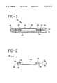
- FIG. 1is a side elevation, partially in section, showing a stent graft constructed in accordance with the present invention contained within a deployment device;
- FIGS. 2 and 3illustrate the stent graft in an unconstrained, radially expanded state, in side and end elevation, respectively;
- FIG. 4is an enlarged view of the stent graft, showing the interbraiding of several textile strands
- FIGS. 5-9schematically illustrate fabrication of the prosthesis
- FIG. 10shows the stent graft of FIG. 2 deployed within a vessel and spanning an aneurysm
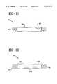
- FIG. 11illustrates an alternative embodiment stent graft with interior and exterior sleeves
- FIG. 12illustrates another alternative stent graft with localized bonding of its latticework and sleeve
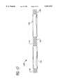
- FIG. 13illustrates another alternative stent graft incorporating auxiliary strands
- FIG. 14illustrates an alternative embodiment stent graft with flexible axial strands
- FIG. 15illustrates an alternative embodiment stent graft with a plastically deformable latticework
- FIG. 16illustrates the stent graft of FIG. 15 mounted on an alternative deployment device
- FIG. 17shows a further alternative stent graft with selectively positioned sleeves
- FIG. 18is a cross-sectional view of a multifilament yarn used in forming a fabric graft according to the invention.
- FIG. 19is a side elevation of a segment of the yarn.
- FIG. 20is an end elevation view of a stent graft in an unconstrained, radially expanded state.
- FIG. 1a deployment device 16 for delivering a stent graft 18 to an intended fixation site or treatment site within a body lumen, then controllably releasing the stent graft for radial self-expansion and fixation within the lumen.
- the deviceincludes an elongate and flexible outer catheter 20 constructed of a biocompatible polymer such as polyurethane.
- a central lumen 22runs the length of catheter 20.
- a distal end region 24 of the outer cathetersurrounds stent graft 18.
- An inner catheter 26is contained within lumen 22 and runs along the entire length of the outer catheter.
- a tapered distal tip 28which extends beyond the outer catheter.
- Stent graft 18surrounds inner catheter 26, confined between the inner and outer catheters.
- a lumen 30 in the inner cathetercan accommodate a flexible guidewire (not shown) tracked by device 16 as it is advanced toward the treatment site.
- Stent graft 18is formed of resilient materials, and in FIG. 1 is shown elastically compressed into a radially-reduced and axially-elongated delivery state.
- Outer catheter 20maintains the stent graft in the delivery state against its elastic restoring force.
- An annular detent 32, mounted to inner catheter 26,occupies a space between the inner and outer catheters to limit proximal travel of the stent graft relative to the inner catheter. As outer catheter 20 is moved proximally relative to inner catheter 26, the detent prevents the stent graft from following the outer catheter.
- inner catheter 26is held stationary while outer catheter 20 is withdrawn proximally.
- the stent graftdoes not expand completely to the relaxed state, and thus exerts a residual force on surrounding tissue that tends to acutely fix the prosthesis.
- the stent grafthas a diameter much larger than the diameter of distal tip 28, so that the inner catheter and tip are proximally withdrawn to leave the stent graft in place.
- Stent graft 18 in FIGS. 2 and 3is shown in a nominal state, in this case a relaxed state in which the stent graft is subject to no external forces. As compared to the delivery state, the prosthesis has a substantially enlarged radius and a substantially reduced axial length.
- the stent grafthas several concentric layers which act in concert during radial expansions and contractions.
- the inside layer(radially) is a latticework 34 formed of resilient monofilament structural strands 36.
- Strands 36are arranged in two sets of parallel helices wound in opposite directions about a common longitudinal axis 38.
- Strands 36intersect one another to define rhombotic interstices and a braid angle a bisected by axis 38.
- the braid angleis in the range of about 60 to 150 degrees, and more preferably 90 to 130 degrees.
- the number of structural strands forming the latticeworkcan range from 10 to 120.
- the braid angleis defined with reference to the nominal state of the latticework. As seen from FIG. 1, radial compression of the stent graft into the delivery state substantially reduces the braid angle.
- the braid anglelargely determines the relationship between radial compression and axial elongation of the prosthesis. Smaller braid angles result in less axial shortening for a given amount of radial enlargement. Conversely, given a larger braid angle, the same radial expansion results in more axial shortening. For a given strand size and strength, a larger braid angle imparts greater resistance to radial compression and more positive acute fixation.
- Structural strands 36are elastic, strong, biocompatible, hemocompatible, and fatigue and corrosion resistant. Materials imparting these desired properties include certain stainless "spring” steels, cobalt-based alloys, and alloys containing titanium. Several preferred cobalt-based alloys are sold under the brand names “Elgiloy,” “Phynox” and “MP35N”. A particularly preferred cobalt-based alloy is a CoCrMo alloy described in U.S. patent application Ser. No. 08/640,253, entitled “Cobalt-Chromium-Molybdenum Alloy Stent and Stent Graft,” filed Apr. 30, 1996 and assigned to the assignee of this application.
- Preferred alloys containing titaniuminclude a recovery metal alloy of nickel and titanium sold under the brand name "Nitinol.”
- Other titanium alloysinclude titanium-zirconium-niobium alloys, and a titanium-aluminum-vanadium alloy known as "TI-6A1-4V.”
- Monofilament structural strands 36can be formed of polymers as well, including PET, polypropylene, PEEK, HDPE, polysulfone, acetyl, PTFE, FEP, and polyurethane. Suitable diameters for the monofilament strands range from about 0.002 inches to about 0.015 inches.
- FIG. 3shows an exterior layer of stent graft 18 as a textile sheeting or sleeve 40, formed of multiple textile strands 42 interwoven with one another.
- FIG. 20shows an alternative embodiment wherein sleeve 40 is an interior layer.
- the textile strandsare braided in a two over two pattern, although a one over one pattern or other patterns are suitable as well.
- the textile strandsintersect one another to define a braid angle ⁇ with sleeve 40 in a nominal state.
- Braid angle ⁇like angle ⁇ , is bisected by axis 38.
- the number of yarns in the polymeric sleevecan range from 20 to 700.
- Textile strands 42preferably are multifilament yarns, although they can be monofilaments. In either case the textile strands are much finer than the structural strands, ranging from about 10 denier to 400 denier. Individual filaments of the multifilament yarns can range from about 0.25 to about 10 denier.
- the multifilament yarnsgenerally have a high degree of compliance, which may or may not include elasticity.
- the multifilament yarnsare composed of PET (Dacron).
- Other acceptable materialsinclude polypropylene, a high molecular weight polyethylene sold under the brand name "Spectra", polyurethane, HDPE, polyethylene, silicone, PTFE, polyolefins and ePTFE.
- the multifilament yarnssuch that the multiple filaments are substantially untwisted and cooperate to form an oblong or non-circular yarn cross-section.
- sleeve 40can be microporous, yet essentially impervious to body fluids.
- the textile sheeting of the sleeveis highly compliant, conforming to changes in the shape of latticework 34 as stent graft 18 either radially self-expands or is radially compressed.
- the shape of the latticeworkdetermines the shape of the stent graft.
- the latticework and sleeveare matched so that when adjusted between their respective nominal and delivery states, they behave according to the same relationship of radial reduction versus axial elongation.
- This relationshipcan be expressed in terms of a percentage of radial contraction for a given percentage of axial elongation, or more succinctly a ratio of contraction to elongation. Such ratio varies with the braid angle. More particularly, at higher braid angles a given radial contraction produces a greater axial extension.
- appropriate matchinginvolves forming latticework 34 and sleeve 40 with the same braid angle, i.e. ⁇ equals ⁇ . Satisfactory matching occurs if ⁇ is within 5 degrees of ⁇ , more preferably if ⁇ is within 3 degrees of ⁇ .
- a highly preferred matchinginvolves selecting angles ⁇ and ⁇ within one degree of each other.
- appropriate matchingmay require a difference in angles ⁇ and ⁇ . For example, where a sleeve is intended to surround a latticework, it may be advantageous to form the fabric sleeve with a braid angle ⁇ less than the corresponding braid angle ⁇ of the latticework.
- the braiding angle of textile strands 42is preferably between 100.91 and 105.45 percent of the braiding angle of structural strands 36. In embodiments such as illustrated in FIG. 20 where graft 40 is disposed inside structural support 34, the braiding angle of textile strands 42 is preferably between 97.72 and 102.27 percent of the braiding angle of structural strands 36.
- Latticework 34 and sleeve 40are integrally secured to one another by an adhesive layer 44, more particularly silicone.
- the silicone adhesiveforms an extremely thin (e.g. 0.005 inches, 0.12 mm) between the latticework and sleeve, adhering to both. Due to the matching of the latticework and sleeve braid angles, adhesive layer 44 is required to accommodate only slight movement of the sleeve relative to the latticework during radial expansions and contractions of the stent graft. Matching avoids a difference in rates of axial elongation that otherwise would unduly stress the adhesive layer and/or cause unwanted stiffness in resistance to bending. As a result, the stent graft is usable over a wider range of radii, elastically compressible to a smaller radius, and able to negotiate more tortuous or serpentine arterial passages.
- Latticework 34is longer than sleeve 40 and extends beyond the opposed ends of the sleeve, providing respective open-mesh end portions 46 and 48 to facilitate acute and long-term fixation. In other embodiments, latticework 34 and sleeve 40 will be congruent in length.
- FIG. 5schematically illustrates a braiding apparatus 50, including an annular carrier assembly 52.
- the carrier assemblysupports multiple bobbins in a circular array, with two of the bobbins indicated at 54 and 56.
- the apparatusfurther includes a cylindrical mandrel 58, centered within the carrier and movable longitudinally relative to the carrier as indicated by the arrow.
- carrier assembly 52is loaded by winding structural strands 36 onto the bobbins.
- the structural strandsare drawn from their respective bobbins to mandrel 58 and braiding proceeds by moving the mandrel longitudinally, while at the same time the bobbins are moved relative to one another as dictated by the desired braiding pattern.
- the resultis an interbraiding Do of structural strands onto the mandrel in two oppositely directed sets of helices, as indicated at 60.
- the mandreldetermines the diameter of the braided structure.
- Mandrel longitudinal speeddetermines the braid angle.
- the latticework lengthsare determined by the duration of braiding, or by cutting the braided structure to desired lengths after its removal from the mandrel.
- FIG. 6illustrates two structural strands (metal monofilaments) 36a and 36b, one from each set of oppositely directed structural strands, wound about a shaping mandrel 62 and supported by respective bobbins 64 and 66. While just strands 36a and 36b are illustrated, it is to be appreciated that all of the structural strands are maintained together about the mandrel for shaping.
- the heat treatmentinvolves age-hardening within a furnace 68 in a vacuum or a protective atmosphere. Temperatures are within the range of about 350-1000 degrees C., with the specific temperature depending on the structural material involved. The monofilaments overlie one another to form multiple intersections, one of which is indicated at 70.
- the bobbins, including bobbins 64 and 66,are set to tension their respective strands during age-hardening. The appropriate duration for age-hardening varies with materials and dimensions, but can range from as brief as thirty seconds, to about five hours.
- structural strands 36retain their helical shapes and collectively determine the nominal or relaxed state of latticework 36.
- the monofilament structural strandsare highly resilient, i.e. deformable under external stress but elastically returning to the nominal state when free of the external stress.
- the structural strands when constructed of a recovery metalare plastically deformable and maintained below an activation temperature, which for nitinol can be below body temperature (about 37 degrees C.).
- an activation temperaturewhich for nitinol can be below body temperature (about 37 degrees C.).
- the latticeworkWhen heated to the activation temperature or above, the latticework returns to the nominal shape.
- the nominal shaperefers to the shape to which the latticework returns when at or above the activation temperature.
- the latticeworkcan be formed of a plastically deformable metal other than a recovery metal.
- the nominal staterefers to the size and shape of the latticework when first formed on the mandrel.
- the latticeworkis plastically deformable to a reduced diameter delivery state, and there is no tendency in the latticework to return to the nominal state, with or without the application of heat.
- the compressed latticeworkis plastically radially expanded toward the nominal state, with a dilatation balloon or other source of external force.
- Heat forming temperaturestypically range from about 100 to about 400 degrees C., and more preferably 150 to 250 degrees C.
- the strandsare maintained at or above the heat forming temperature for a duration generally shorter than that of thermally setting metal strands, i.e. from about thirty seconds to about two hours, or more preferably five to fifteen minutes.
- Sleeve 40is formed by braiding textile strands 42 about a mandrel, again in two sets of parallel, oppositely directed helices. Braiding apparatus 50 or a similar device can be used. The multifilament yarns can be wound about mandrel 58, or another mandrel with a slightly larger diameter.
- a primary considerationis to select braid angle ⁇ with respect to braid angle ⁇ of the latticework, to closely match the geometrical diameter and elongation properties of the latticework and sleeve when these components are formed into the stent graft. With latticework 34 and sleeve 40 both composed of helically wound strands, this is accomplished in most cases by matching the respective braid angles, with matching on occasion involving a slight difference in the braid angles, as noted above.
- braid angle ⁇is intentionally set a few degrees less than braid angle ⁇ .
- sleeve 40surrounds latticework 34 in the finished stent graft, it necessarily is expanded to a slightly larger radius, which entails increasing braid angle ⁇ toward coincidence with braid angle ⁇ .
- textile strands 42can be braided at the same braid angle as the latticework, but on a larger diameter mandrel to account for the fact that sleeve 40 surrounds latticework 34 and the intermediate adhesive.
- these approachescan be combined, with the textile strands braided at a slightly reduced braid angle on a slightly larger mandrel.
- the textile strandsare thermally set while wound about a shaping mandrel, to give sleeve 40 its nominal state.
- the multifilament yarnsare thermally set in substantially the same manner as the thermoplastic structural strands.
- the multifilament yarnsare thermally set at temperatures ranging from 150 to 250 degrees C., for times ranging from 1 to 30 minutes. More preferably, setting temperatures range from 180 to 210 degrees C., and the time for setting is about 3-5 minutes.
- sleeve 40is cut to the desired length using a laser, which introduces localized fusing at the ends of the strands to prevent unraveling.
- the latticework and sleeveare formed independently of one another. This is advantageous from the standpoint of allowing braiding and thermal setting conditions to be tailored specifically in each case to the strand structure and material involved.
- latticework 34is formed of metallic strands, the independent fabrication is essential in many cases, since the higher temperatures needed for age-hardening are above the melting points of polyesters and other materials suitable for the multifilament yarn textile strands.
- the completed sleeve and latticeworkare bonded to one another.
- the bondextends circumferentially about the interface between the latticework exterior surface and sleeve interior surface, over the complete axial length of the annular region over which the sleeve and latticework are adjacent one another.
- the bondshould be highly uniform over the entire region, to avoid stress concentrations and ensure a more uniform behavior of the stent graft during bending, radial expansions and radial contractions.
- a siloxane polymer(silicone) is used as the adhesive and is applied as a uniformly thick coating to latticework 34.
- the siliconeis dispersed in an organic solvent of xylene and THF (tetrahydrafuran) at a concentration of about 6% of the silicon polymer, by weight.
- Suitable alternative organic solventsinclude toluene and trichloroethylene.
- Suitable alternative polymersinclude fluorosilicone and polycarbonate urethane.
- Alternative adhesivesinclude polycarbonate urethanes such as disclosed in U.S. Pat. No. 5,229,431 (Pinchuk).
- latticework 34is placed in a fixture 72 that rotates the latticework about axis 38 at a speed of about 100 rotations per minute.
- a spraying device 74e.g. an air brush
- the xylene and THFare allowed to evaporate, leaving as a residue the silicone polymer, thus forming a uniform adhesive coating over the latticework.
- a polymeric adhesive in powdered forme.g. polypropylene or polyethylene
- a polymer in powdered formcan be electrostatically deposited onto the latticework according to a technique known to those skilled in the art.
- the polymer when appliedis kept below its melting point, although it may reach a fusion or glass transition temperature. Later, during bonding of the latticework and sleeve, the polymer is heated at least to its melting temperature.
- the adhesivecan be applied by a hot melt process, in which a polymer (e.g. polyurethane) is applied to the latticework in liquid form.
- a polymere.g. polyurethane
- the latticework and sleeveare assembled by axially elongating the latticework to reduce its radius, then inserting the reduced-radius latticework into sleeve 40 while the sleeve is maintained in its nominal state. Then, the silicone-coated latticework is allowed to axially shorten and radially expand into a surface engagement with the radially inside surface of sleeve 40. The thickness of the silicone coating is taken into account in the sizing of the sleeve and latticework with respect to one another.
- the stent graftis maintained in an oven 76 (FIG. 9) at temperatures in the range of 125-200 degrees C., for a time ranging from 20 minutes to about one hour. More preferably, the temperature is about 150 degrees C. and the time is about 30 minutes.
- the stent graftis removed from the oven and allowed to cool to ambient temperature.
- the cured silicone polymeradheres to sleeve 40 as well as the latticework, causing stent graft 18 to behave as a unitary structure, notwithstanding its three distinct layers 34, 40, and 44 as discussed above.
- stent graft 18combines the favorable attributes of self-expanding stents and grafts.
- Latticework 34provides radial compressibility, self-expansion over a wide range of radii and a residual force sufficient for acute fixation, while sleeve 40 provides reduced permeability so that the stent graft is essentially impervious to blood and other body fluids.
- the stent graftis particularly well suited for treating an aneurysm.
- FIG. 10illustrates fixation of stent graft 18 within a blood vessel having a vessel wall 78. Along the vessel wall is an aneurysm 80.
- Opposite end portions 46 and 48 of the stent graftare radially expanded into intimate contact with vessel wall 78 on opposite sides of the aneurysm.
- a medial region 82 of the stent graftspans the aneurysm.
- End portions 46 and 48effectively fix the stent graft, due to the resilience and strength of the structural strand latticework. Fixation is enhanced by the exposed end portions. Because of the open weave latticework structure, end portions 46 and 48 more effectively engage surrounding tissue for a better acute fixation. The open structure also promotes fibrotic ingrowth, which is desirable near the end portions because it improves chronic fixation.
- the latticeworkis produced by setting up a 48 carrier braiding apparatus in a one over one diamond braid pattern, using 24 of the carriers.
- the corresponding 24 bobbinsare loaded with a 0.0055 inch diameter Elgiloy wire.
- a 10.0 mm diameter round mandrelis placed onto the puller of the braiding device.
- the Elgiloy wiresare threaded through their respective carriers and attached to the mandrel.
- the braiding apparatusis set to form a braid angle of 110 degrees. When an adequate length of the braid is formed, the latticework is removed from the mandrel.
- the latticeworkis mounted onto a shaping mandrel and heat treated in a vacuum furnace, increasing the strength of the Elgiloy strands as well as inducing a more permanent memory into the strands to set the normal state of the latticework.
- the polymeric sleeveis formed on a 192 carrier braiding apparatus, set in a two over two braid pattern using all 192 carriers.
- the corresponding bobbinsare loaded with a 40 denier, 27 filament polyester yarn.
- a 10.5 mm diameter mandrelis inserted into the puller.
- the braideris operated to form a braid angle of 107 degrees.
- the sleeveis removed from the braiding mandrel.
- the sleeveis thermally set on a shaping mandrel at a temperature of 205 degrees C. for about 5 minutes.
- the sleeveis ultrasonically cleaned to remove any finish on the yarn.
- the sleeve lengthis determined by laser cutting at the opposite ends to prevent unraveling.
- An uncured silicone polymeris applied to the Elgiloy latticework, sprayed onto the latticework as a liquid solution with the silicone at six percent by weight.
- the silicone solutionis sprayed onto the latticework at an air pressure of about 15 psi. Spraying occurs intermittently in sets of several (preferably three) passes of the airbrush sprayer, allowing several seconds for settling between sets of airbrush passes, until an amount of solution corresponding to a desired thickness has been sprayed, i.e. approximately 26 ml for the 10 mm diameter latticework.
- the silicone solutioncan be applied in a continuous spray, typically lasting about 5 minutes.
- the coated latticeworkis allowed to air dry to a tacky condition, then constrained to an axially elongated reduced radius state for insertion into the completed sleeve. Grips holding opposite ends of the latticework are moved towards one another slowly, to effect a gradual return of the latticework toward its nominal radius, and toward engagement with the surrounding sleeve. Once the latticework is completely released and engaged with the sleeve, the stent graft is cured at 150 degrees C. for thirty minutes.
- a latticework 84 and surrounding polyester sleeve 86are formed as before.
- a second polyester sleeve 88for use as an interior sleeve surrounded by the latticework, is braided on a 10.0 mm mandrel, with the braider operated to form a braid angle of 107 degrees.
- the latticeworkis axially elongated and inserted into the exterior sleeve, then allowed to gradually radially expand against the sleeve as before.
- the second, inner polyester sleeveis axially elongated, placed within the latticework and exterior sleeve, and radially expanded into engagement against the latticework.
- a 9.5 mm mandrelinserted into the interior sleeve, further urges the sleeve radially outward and into contact with the latticework.
- the stent graftincluding the latticework and the interior and exterior sleeves, is maintained at 150 degrees C. for thirty minutes to cure the silicone adhesive.
- the resulting stent graft 90is shown in FIG. 11.
- a latticework and exterior polyester sleeveare formed as before.
- the latticeworkis sprayed with a silicone solution as before, but only along two opposite end regions, leaving a medial segment of the latticework uncovered.
- the latticeworkwas axially elongated, inserted within the sleeve and allowed to radially expand against the sleeve, as in the previous examples. Oven curing was substantially the same.
- the result, shown in FIG. 12,is a stent graft 92 with exposed ends 94 and 96 of the latticework coated with silicone. Opposite end bond regions 98 and 100 have axial lengths of about 17 mm, where the latticework and sleeve are bonded together. Over a medial region 102, the sleeve and latticework are adjacent one another and in surface contact, but not bonded. Where the stent graft is provided to an end user in elongated tubular form, with the intention that the end user will cut the tube to the desired lengths, bonding along the full lengths of the latticework and sleeve is recommended.
- Stent graftscan be fabricated to impart a variety of desired qualities.
- FIG. 13shows a stent graft 104 formed with a latticework 106 of structural strands surrounded by a sleeve 108 of textile strands.
- An auxiliary strand 110is interbraided with the textile strands.
- Strand 110can be formed of a radiopaque material, e.g. tantalum, to improve fluoroscopic imaging of the stent graft.
- biological or bioabsorbable strandscan be interwoven in this fashion.
- FIG. 14illustrates a stent graft 112 in which polyurethane monofilaments have been incorporated into the latticework as axial runners 114.
- the braiding apparatusis provided with an appropriate number of triaxial guide tubes arranged about the carrier assembly. One of the polyurethane monofilaments is fed into each of the triaxial guide tubes.
- the polyurethane runnersare heated sufficiently to fuse them to the remaining structure. The axial runners enhance radial recovery of the graft and reduce the tendency to unravel or fray.
- Another improvementis a coating of the multifilament yarn textile strands with TFE (tetrafluoroethylene) or a copolymer of TFE and silicone.
- the coatingwhich can be applied by plasma polymerization before braiding the sleeve, enhances surface properties of the yarn, e.g. by reducing friction.
- the resulting stent graftcan be deployed with less force and inflammatory responses to the implanted stent graft may be reduced.
- a plasma polymerizationcan occur after fabrication of the stent graft, to coat the exterior surface of the sleeve.
- FIG. 15discloses an alternative latticework 116, formed by a series of plastically deformable sinusoidal strands 118 joined to one another at multiple points 120.
- Latticework 116can be plastically adjusted by a combined radial reduction and axial elongation.
- Strands 118are metallic, but formed of metals much more ductile and malleable than the metals forming latticework 34 (for example).
- latticework 116can be formed of plastically deformable strands arranged in sets of oppositely directed helices.
- FIG. 16illustrates the distal end region of a catheter 122 used to deploy a stent graft 124 including latticework 116.
- Stent graft 124is governed by the structural characteristics of latticework 116 and thus remains in the axially elongated radially reduced delivery state as shown, without an additional catheter or other constraining feature.
- the stent grafthas no tendency to elastically resume its larger radius nominal state.
- an auxiliary forcing featureis required to urge the stent graft, once properly positioned, toward its normal state.
- a dilatation balloon 126is mounted to catheter 122 and surrounded by the stent graft. The balloon, when inflated by the introduction of fluid under pressure through a lumen in catheter 122, radially expands the stent graft.
- FIG. 17shows a stent graft 128 with a latticework 130 surrounded by proximal and distal sleeves 132 and 134.
- the latticeworkis exposed at stent graft end portions 136 and 138, for improved acute and long-term fixation as explained above.
- Each of sleeves 132 and 134is positionable along an intraluminal location where shunting of the blood flow is desired.
- An exposed medial region 140 between sleeves 132 and 134is positionable in alignment with a branch of the vessel being treated, so that stent graft 128 can provide the intended shunting without blocking flow between the main vessel and the branch between the two shunting areas.
- Stent graft 128is fabricated according to the process discussed above, i.e. with the latticework and sleeves being independently braided, then bonded with a silicone adhesive over the cylindrical regions along which the sleeves and latticework are adjacent, i.e. along the axial lengths of the sleeves.
- Sleeves 132 and 134, or any number of sleeves,are bonded to the latticework in a single curing operation.
- Sleeves 132 and 134can be cut from the same braiding of textile strands, or braided independently, for example if different diameter sleeves are desired. In any event a stent graft can be tailored to meet specific needs by altering variables such as the number of sleeves employed, the diameter and axial length of the sleeves, and their positioning along the latticework.
- the multifilament yarns used in commercially available textile vascular graftsare twisted yarns, i.e. the multiple filaments making up the yarn have surface twist angles in the range of about 15 degrees to about 45 degrees.
- the multiple filamentscharacteristically define a circular yarn cross-section. This structure has been favored, because such yarns are structurally stable and lend themselves well to handling by the equipment used in weaving and knitting processes.
- this yarn structureis a detriment to stent graft performance in several respects.
- the high degree of filament twistingcan cause kinking of the fabric when the stent graft is bent, which limits the curvature of vessels in which the stent graft can be deployed and implanted.
- the multifilamentsare tightly packed, with the packing factor (ratio of cross-sectional area of the combined filaments to the cross-sectional area of the yarn as a whole) in the range of 0.7-0.9.
- the packing factorratio of cross-sectional area of the combined filaments to the cross-sectional area of the yarn as a whole
- the circular cross-sectionsets a minimum dimension for the stent graft, in that the fabric graft wall is preferably at least as thick as two yarn diameters.
- the fabric coverageis undesirably low because of the circular yarn cross-section, i.e. usually below 80 percent without additional compacting.
- the fabric porosityis undesirably high, usually above 70 percent without additional compacting.
- a textile strand or yarn 142is composed of multiple filaments 144 arranged to define a yarn cross-sectional shape with an aspect ratio slightly greater than three.
- the aspect ratiois defined as:
- fis the aspect ratio
- wis the cross-sectional width
- tis the cross-sectional thickness.
- the values w and talso can be thought of as respective major and minor axes of the yarn cross-section.
- the yarn as shown in FIG. 18consists of untwisted fibers having circular cross-sections. In cases where the fibers are twisted, their cross-sections would appear eliptical. While satisfactory non-circular cross-sections can have aspect ratios up to about 20, preferred aspect ratios are in a range from about 2 to about 12.
- FIG. 19illustrates a segment of multifilament yarn 142, showing the surface twist angle of the multiple filaments that make up the yarn.
- Filaments 144are helically arranged, and the surface twist angle is the angle of incline of the filament with respect to a longitudinal axis 146 of the yarn, in the same sense that braid angles ⁇ and ⁇ are defined with respect to longitudinal axes of their respective tubular structures.
- the preferred twist angle of the filamentsis at most about 5 degrees, significantly less than surface twist angles typical of conventional twisted yarns, typically with surface twist angles in the range of 15-45. Because of the reduced twist angle, yarn 142 can be formed with a considerably reduced packing factor. The result is more interstitial space within the yarn for fibrotic ingrowth, for more secure chronic fixation of the sleeve.
- the use of multifilament yarns with the preferred non-circular cross-sections, and in which the filaments are essentially untwisted,provides several performance advantages.
- the lack of any substantial twistingleads to a wider range of fiber packing, with packing factors ranging from 0.5-0.9.
- the fiber packing factor kis defined as:
- nis the number of filaments or fibers in the yarn
- Afis the cross-sectional area of each fiber
- Ayis the total cross-sectional area of the yarn.
- the preferred non-circular yarn cross sectionscooperate with the more loosely packed filaments to improve elongation properties. More particularly, the yarn cross-sectional shape can change, narrowing as the sleeve is elongated, then widening as the sleeve recovers towards its nominal length.
- the higher aspect ratio, "flattened" yarnscan be made with a reduced thickness without diminishing strength, since strength is a function largely of the yarn cross-sectional area.
- the yarn's thicknessbeing less than one-third of its width, as illustrated in FIG. 18, the result is a substantial reduction in thickness of the fabric sleeve.
- This featurein cooperation with improved elongation capability, enables delivery of the stent graft to treatment sites in narrower vascular passages.
- Yet another benefit of the increased aspect ratiois the combination of better fabric coverage and reduced fabric porosity, thus reduced permeability to water and other fluids.
- Textile stranda twisted, 80 denier PET multifilament yarn, having an aspect ratio of 1, and a packing factor of 0.75.
- Fabric sleeveinside diameter of 10 mm, braid angle of 110 degrees, 192 yarn ends, fabric thickness of 0.0073 inches, yarn coverage of 66 percent, and fabric porosity of 76 percent.
- Table 1illustrates structural changes in the fabric sleeve and yarn, accompanying radial contraction and axial elongation of the sleeve:
- Textile strand40 denier PET multifilament yarn, without any substantial twisting of the filaments, with a yarn aspect ratio of 3.66 and a filament packing factor of 0.50.
- Fabric sleeveinside diameter of 10 mm, braid angle of 110 degrees, fabric thickness of 0.0032 inches, yarn coverage of 95 percent, and fabric porosity of 60 percent.
- Table 2illustrates structural changes in the fabric sleeve and the yarn, as the fabric sleeve is radially contracted and axially expanded.
- the preferred devicehas a much thinner fabric wall, both in the nominal state (no axial expansion) and when axially expanded. This augments the improved elongation capability, to further reduce the diameter of the sleeve in the delivery state.
- the yarn coverage or fabric coverageis significantly higher (95 percent versus 66 percent), and the fabric porosity is significantly lower (60 percent versus 76 percent), resulting in lower permeability.
- porosity on a "micro" scalei.e. throughout the yarn cross-section, is substantially greater, resulting in more tissue ingrowth, and thus improved chronic fixation.
- the preferred sleeverequires less material (40 denier yarn as compared to 80 denier yarn).
- the yarn cross-section aspect ratiois reduced from 3.66 before elongation to 1.15 at complete elongation. This illustrates the extent to which the yarn cross-section undergoes changes in its profile to accommodate the axial elongation.
- the less preferred circular cross-sectional yarnretains its aspect ratio of unity during elongation.
- the fabric thickness of the sleeve employing the twisted yarnremains essentially the same during axial elongation, although slightly decreasing near the end.
- the fabric thickness of the preferred sleevealso remains constant through most of the axial elongation, but increases substantially near the end because of the reduced yarn diameter resulting from increased fiber packing.
- parameters relating to the yarns and fabricscan be tailored to achieve desired physical properties.
- thinner walls for the fabric sleeveare preferred, so long as the fabric sleeve meets water permeability, longitudinal strength and radial burst strength requirements.
- Yarn cross-sectional aspect ratios in the preferred range of 2-12permit substantial thinning of the fabric sleeve without sacrificing longitudinal or radial strength.
- the filament or fiber packing factorshould be optimized to balance the desire for tissue ingrowth with the need for graft permeability.
- the filament packing in textured yarnsis optimal at packing factors of 0.50-0.55 in the unconstrained state.
- Flat yarnsare characterized by higher optimum densities, with favored packing factors from about 0.60 to about 0.65 in the unconstrained state.
- the selection of yarn cross-sectional aspect ratiosalso require optimizing. Higher aspect ratios lead to improved axial elongation properties. However, they also reduce the degree of yarn (filament) interlocking, thus tending to reduce fabric stability.
- the preferred aspect ratio range of 2-12has been found to satisfy these competing needs, with the lower end of the range favoring stability while the higher end favors enhanced elongation.
- the yarn coverage ratiopreferably is as high as possible to achieve minimum yarn interstices, while fabric porosity is kept low to meet water permeability requirements.
- the number of yarn endsshould be fixed after determining several other factors, including braid angle, sleeve diameter, fabric thickness, yarn linear density, packing factor, and aspect ratio.
- Table 3illustrates several examples of fabric sleeves for use in stent grafts.
- the textile strandshave a packing factor of 0.54, and are braided at a braid angle of 110 degrees.
- a stent graftis formed with distinct layers to provide the structural advantages of stents with the capacity of grafts for shunting blood and other body fluids.
- the stent graftis adjustable in size by simultaneous radial reduction and axial elongation, or simultaneous radial enlargement and axial shortening.
- the separate layersare configured to behave according to substantially the same relationship of radial change with respect to axial change, so that the graft behaves as a unitary structure during radial enlargements and reductions.
- the layered constructioninvolves independent formation of latticework and microporous sleeves followed by their bonding, a process that reduces cost and promotes a customizing of stent grafts through sselective positioning of sleeves to leave areas of the latticework exposed.
Landscapes
- Health & Medical Sciences (AREA)
- Engineering & Computer Science (AREA)
- Biomedical Technology (AREA)
- Cardiology (AREA)
- Oral & Maxillofacial Surgery (AREA)
- Transplantation (AREA)
- Heart & Thoracic Surgery (AREA)
- Vascular Medicine (AREA)
- Life Sciences & Earth Sciences (AREA)
- Animal Behavior & Ethology (AREA)
- General Health & Medical Sciences (AREA)
- Public Health (AREA)
- Veterinary Medicine (AREA)
- Manufacturing & Machinery (AREA)
- Textile Engineering (AREA)
- Gastroenterology & Hepatology (AREA)
- Pulmonology (AREA)
- Mechanical Engineering (AREA)
- Prostheses (AREA)
- Media Introduction/Drainage Providing Device (AREA)
- Materials For Medical Uses (AREA)
Abstract
Description
f=w/t
k=n(Af)/(Ay)
TABLE 1__________________________________________________________________________Inner Fabric Braiding Fabric Yarn Fabric Yarn Fiber PackingDiameter Elongation Angle Thickness Coverage Porosity Aspect Ratio Factor__________________________________________________________________________10.00 mm 0% 110N 0.0073" 66% 76% 1.0 0.759.00mm 18% 95N 0.0073" 71% 73% 1.0 0.758.00mm 32% 82N 0.0073" 72% 73% 1.0 0.757.00 mm 43% 70N 0.0073" 74% 72% 1.0 0.756.00mm 52% 59N 0.0067" 75% 66% 1.0 0.805.85 mm 53% 57N 0.0066" 75% 65% 1.0 0.91__________________________________________________________________________
TABLE 2__________________________________________________________________________Inner Fabric Braiding Fabric Yarn Fabric Yarn Fiber PackingDiameter Elongation Angle Thickness Coverage Porosity Aspect Ratio Factor__________________________________________________________________________10.00 mm 0% 110N 0.0032" 95% 60% 3.66 0.549.00mm 18% 95N 0.0032" 96% 63% 3.92 0.508.00mm 32% 82N 0.0032" 96% 63% 3.85 0.507.00 mm 43% 70N 0.0032" 95% 61% 3.66 0.546.00mm 52% 59N 0.0032" 94% 58% 3.16 0.605.00 mm 59% 48N 0.0032" 92% 53% 2.62 0.724.00 mm 65% 38N 0.0046" 77% 65% 1.11 0.843.83mm 66% 36N 0.0043" 78% 61% 1.15 0.91__________________________________________________________________________
TABLE 3__________________________________________________________________________Inner Number of Yarn Linear Fabric Yarn Fabric Yarn AspectDiameter Yarn Ends Density Thickness Coverage Porosity Ratio__________________________________________________________________________6mm 72 70 0.0031" 98% 55% 6.536mm 96 50 0.0032" 97% 58% 4.626mm 120 40 0.0034" 94% 62% 3.156mm 144 30 0.0032" 93% 64% 2.6912 mm 192 50 0.0032" 97% 58% 4.6224 mm 352 60 0.0035" 97% 58% 4.5640 mm 512 70 0.0034" 98% 56% 5.45__________________________________________________________________________
Claims (28)
Priority Applications (2)
| Application Number | Priority Date | Filing Date | Title |
|---|---|---|---|
| US08/946,906US5957974A (en) | 1997-01-23 | 1997-10-08 | Stent graft with braided polymeric sleeve |
| US09/321,181US6500203B1 (en) | 1997-01-23 | 1999-05-27 | Process for making stent graft with braided polymeric sleeve |
Applications Claiming Priority (2)
| Application Number | Priority Date | Filing Date | Title |
|---|---|---|---|
| US3616097P | 1997-01-23 | 1997-01-23 | |
| US08/946,906US5957974A (en) | 1997-01-23 | 1997-10-08 | Stent graft with braided polymeric sleeve |
Related Child Applications (1)
| Application Number | Title | Priority Date | Filing Date |
|---|---|---|---|
| US09/321,181DivisionUS6500203B1 (en) | 1997-01-23 | 1999-05-27 | Process for making stent graft with braided polymeric sleeve |
Publications (1)
| Publication Number | Publication Date |
|---|---|
| US5957974Atrue US5957974A (en) | 1999-09-28 |
Family
ID=21886999
Family Applications (2)
| Application Number | Title | Priority Date | Filing Date |
|---|---|---|---|
| US08/946,906Expired - LifetimeUS5957974A (en) | 1997-01-23 | 1997-10-08 | Stent graft with braided polymeric sleeve |
| US09/321,181Expired - Fee RelatedUS6500203B1 (en) | 1997-01-23 | 1999-05-27 | Process for making stent graft with braided polymeric sleeve |
Family Applications After (1)
| Application Number | Title | Priority Date | Filing Date |
|---|---|---|---|
| US09/321,181Expired - Fee RelatedUS6500203B1 (en) | 1997-01-23 | 1999-05-27 | Process for making stent graft with braided polymeric sleeve |
Country Status (7)
| Country | Link |
|---|---|
| US (2) | US5957974A (en) |
| EP (1) | EP0855170B1 (en) |
| JP (1) | JP4044192B2 (en) |
| AT (1) | ATE308940T1 (en) |
| AU (1) | AU730316B2 (en) |
| CA (1) | CA2227654C (en) |
| DE (1) | DE69832218T2 (en) |
Cited By (231)
| Publication number | Priority date | Publication date | Assignee | Title |
|---|---|---|---|---|
| US6249952B1 (en)* | 1997-08-04 | 2001-06-26 | Scimed Life Systems, Inc. | Method for manufacturing an expandable stent |
| US20010056299A1 (en)* | 1996-04-30 | 2001-12-27 | Thompson Paul J. | Three-dimensional braided covered stent |
| US6334868B1 (en) | 1999-10-08 | 2002-01-01 | Advanced Cardiovascular Systems, Inc. | Stent cover |
| US6342068B1 (en)* | 1996-04-30 | 2002-01-29 | Schneider (Usa) Inc | Three-dimensional braided stent |
| US6348068B1 (en)* | 1999-07-23 | 2002-02-19 | Sulzer Carbomedics Inc. | Multi-filament valve stent for a cardisc valvular prosthesis |
| US6368346B1 (en) | 1999-06-03 | 2002-04-09 | American Medical Systems, Inc. | Bioresorbable stent |
| US6379382B1 (en) | 2000-03-13 | 2002-04-30 | Jun Yang | Stent having cover with drug delivery capability |
| US6383171B1 (en) | 1999-10-12 | 2002-05-07 | Allan Will | Methods and devices for protecting a passageway in a body when advancing devices through the passageway |
| WO2002036046A2 (en) | 2000-10-31 | 2002-05-10 | Boston Scientific Limited | Braided, branched, implantable device and processes for manufacture thereof |
| US6398807B1 (en) | 2000-01-31 | 2002-06-04 | Scimed Life Systems, Inc. | Braided branching stent, method for treating a lumen therewith, and process for manufacture therefor |
| WO2002047579A1 (en)* | 2000-12-12 | 2002-06-20 | Cardiatis Société Anonyme | Three-dimensional braided structure stent |
| WO2002022049A3 (en)* | 2000-09-12 | 2002-08-08 | Georgios Archodoulakis | Implantable prosthesis for intravascular applications |
| US6478813B1 (en) | 1997-08-01 | 2002-11-12 | Peter T. Keith | Method for joining grafts in a common body passageway |
| US6482227B1 (en) | 1998-03-30 | 2002-11-19 | Cordis Corporation | Stent graft having improved attachment within a body vessel |
| US6500203B1 (en)* | 1997-01-23 | 2002-12-31 | Boston Scientific Scimed, Inc. | Process for making stent graft with braided polymeric sleeve |
| US20030017775A1 (en)* | 2001-06-11 | 2003-01-23 | Scimed Life Systems. Inc.. | Composite ePTFE/textile prosthesis |
| US20030055479A1 (en)* | 1999-11-16 | 2003-03-20 | Iowa-India Investments Company, Limited | Encapsulated stent preform |
| US20030069629A1 (en)* | 2001-06-01 | 2003-04-10 | Jadhav Balkrishna S. | Bioresorbable medical devices |
| US6551352B2 (en) | 2001-05-03 | 2003-04-22 | Bionx Implants, Inc. | Method for attaching axial filaments to a self expanding stent |
| US20030088308A1 (en)* | 2000-09-18 | 2003-05-08 | Inflow Dynamics Inc. | Primarily niobium stent |
| US6575994B1 (en) | 1994-02-10 | 2003-06-10 | Teramed, Inc. | Method and apparatus concerning bypass grafts |
| US20030139804A1 (en)* | 1995-11-27 | 2003-07-24 | Schneider (Europe) Ag, A/K/A Schneider (Europe) Gmbh | Conical stent |
| US20030144728A1 (en)* | 2000-09-18 | 2003-07-31 | Inflow Dynamics Inc. | Metal stent with surface layer of noble metal oxide and method of fabrication |
| US6613082B2 (en) | 2000-03-13 | 2003-09-02 | Jun Yang | Stent having cover with drug delivery capability |
| US20030176911A1 (en)* | 2000-05-01 | 2003-09-18 | Octavian Iancea | Modular graft component junctions |
| US6622604B1 (en) | 2000-01-31 | 2003-09-23 | Scimed Life Systems, Inc. | Process for manufacturing a braided bifurcated stent |
| US6626938B1 (en) | 2000-11-16 | 2003-09-30 | Cordis Corporation | Stent graft having a pleated graft member |
| US6629992B2 (en)* | 2000-08-04 | 2003-10-07 | Advanced Cardiovascular Systems, Inc. | Sheath for self-expanding stent |
| US20030199973A1 (en)* | 2002-02-26 | 2003-10-23 | Chuter Timothy A.M. | Endovascular grafting device |
| US20030204248A1 (en)* | 2002-03-25 | 2003-10-30 | Murphy Kieran P. | Device viewable under an imaging beam |
| US6641607B1 (en) | 2000-12-29 | 2003-11-04 | Advanced Cardiovascular Systems, Inc. | Double tube stent |
| US6645242B1 (en) | 2000-12-11 | 2003-11-11 | Stephen F. Quinn | Bifurcated side-access intravascular stent graft |
| US6649030B1 (en) | 2000-08-31 | 2003-11-18 | Endovascular Technologies, Inc. | Physical vapor deposition of radiopaque markings on a graft |
| US20030229389A1 (en)* | 2000-05-01 | 2003-12-11 | Escano Arnold M. | Lock modular graft component junctions |
| US6685738B2 (en) | 2000-01-31 | 2004-02-03 | Scimed Life Systems, Inc. | Braided endoluminal device having tapered filaments |
| US6699274B2 (en)* | 2001-01-22 | 2004-03-02 | Scimed Life Systems, Inc. | Stent delivery system and method of manufacturing same |
| US6709514B1 (en)* | 2001-12-28 | 2004-03-23 | Advanced Cardiovascular Systems, Inc. | Rotary coating apparatus for coating implantable medical devices |
| US6712843B2 (en)* | 2001-11-20 | 2004-03-30 | Scimed Life Systems, Inc | Stent with differential lengthening/shortening members |
| US20040098095A1 (en)* | 1997-12-18 | 2004-05-20 | Burnside Diane K. | Stent-graft with bioabsorbable structural support |
| US20040133264A1 (en)* | 2000-02-04 | 2004-07-08 | Moore Scott T. | Stent introducer apparatus |
| US20040138644A1 (en)* | 2003-01-15 | 2004-07-15 | Scimed Life Systems, Inc. | Intraluminally placeable textile catheter, drain and stent |
| US6773454B2 (en) | 2000-08-02 | 2004-08-10 | Michael H. Wholey | Tapered endovascular stent graft and method of treating abdominal aortic aneurysms and distal iliac aneurysms |
| US20040176740A1 (en)* | 2003-03-05 | 2004-09-09 | Scimed Life Systems, Inc. | Multi-braid exterior tube |
| US20040182511A1 (en)* | 2001-06-11 | 2004-09-23 | Scimed Life Systems, Inc. | Pressure lamination method for forming composite ePTFE/textile and ePTFE/stent/textile prostheses |
| US20040215337A1 (en)* | 2003-04-24 | 2004-10-28 | Scimed Life Systems, Inc. | AV grafts with rapid post-operative self-sealing capabilities |
| US20040230286A1 (en)* | 2003-03-10 | 2004-11-18 | Moore Scott T. | Stent introducer apparatus |
| US20040251725A1 (en)* | 2001-11-08 | 2004-12-16 | Clive Jenkins | Chairs |
| WO2003088820A3 (en)* | 2002-04-19 | 2004-12-29 | Broncus Tech Inc | Devices for maintaining surgically created openings |
| US20050004646A1 (en)* | 2003-07-01 | 2005-01-06 | Moriarty James W. | Energy-activated adhesion layer for drug-polymer coated stent |
| US6843802B1 (en) | 2000-11-16 | 2005-01-18 | Cordis Corporation | Delivery apparatus for a self expanding retractable stent |
| US20050049672A1 (en)* | 2003-03-24 | 2005-03-03 | Murphy Kieran P. | Stent delivery system and method using a balloon for a self-expandable stent |
| US20050075656A1 (en)* | 2003-09-30 | 2005-04-07 | Jean Beaupre | Applier for a surgical device |
| US6887268B2 (en) | 1998-03-30 | 2005-05-03 | Cordis Corporation | Extension prosthesis for an arterial repair |
| US20050110214A1 (en)* | 2003-11-25 | 2005-05-26 | Shank Peter J. | Composite stent with inner and outer stent elements and method of using the same |
| US20050165352A1 (en)* | 2004-01-23 | 2005-07-28 | Scimed Life Systems, Inc. | Stent delivery catheter |
| US6942692B2 (en) | 2000-11-16 | 2005-09-13 | Cordis Corporation | Supra-renal prosthesis and renal artery bypass |
| US20050222669A1 (en)* | 2004-03-31 | 2005-10-06 | Purdy James D | Fenestrated intraluminal stent system |
| US20050222668A1 (en)* | 2003-11-08 | 2005-10-06 | Schaeffer Darin G | Flareable branch vessel prosthesis and method |
| US20050222664A1 (en)* | 2004-04-06 | 2005-10-06 | Parker Fred T | Prosthesis deployment system |
| US20050234334A1 (en)* | 2002-03-25 | 2005-10-20 | Murphy Kieran P | Kit for image guided surgical procedures |
| US20050256580A1 (en)* | 2002-11-29 | 2005-11-17 | Dsm Ip Assets B.V. | Artificial intervertebral disc |
| US20050261781A1 (en)* | 2004-04-15 | 2005-11-24 | Sennett Andrew R | Cement-directing orthopedic implants |
| US20050283222A1 (en)* | 2000-09-18 | 2005-12-22 | Endotex Interventional Systems, Inc. | Apparatus for delivering endoluminal prostheses and methods of making and using them |
| US20050288775A1 (en)* | 2004-06-24 | 2005-12-29 | Scimed Life Systems, Inc. | Metallic fibers reinforced textile prosthesis |
| US20060015136A1 (en)* | 2002-09-19 | 2006-01-19 | Memory Metal Holland Bv | Vascular filter with improved strength and flexibility |
| US20060025844A1 (en)* | 2004-07-28 | 2006-02-02 | Majercak David C | Reduced deployment force delivery device |
| US20060034883A1 (en)* | 2001-12-21 | 2006-02-16 | Dang Mai H | Composite stent with polymeric covering and bioactive coating |
| US20060116752A1 (en)* | 2004-11-10 | 2006-06-01 | Boston Scientific Scimed, Inc. | Atraumatic stent with reduced deployment force, method for making the same and method and apparatus for deploying and positioning the stent |
| US20060135943A1 (en)* | 2002-09-30 | 2006-06-22 | Evgenia Mandrusov | Method and apparatus for treating vulnerable plaque |
| US20060241690A1 (en)* | 2004-03-19 | 2006-10-26 | Aga Medical Corporation | Multi-layer braided structures for occluding vascular defects and for occluding fluid flow through portions of the vasculature of the body |
| US20060253184A1 (en)* | 2005-05-04 | 2006-11-09 | Kurt Amplatz | System for the controlled delivery of stents and grafts |
| US20060265043A1 (en)* | 2002-09-30 | 2006-11-23 | Evgenia Mandrusov | Method and apparatus for treating vulnerable plaque |
| EP1768612A1 (en)* | 2004-07-07 | 2007-04-04 | Cook Incorporated | Graft, stent graft and method for manufacture |
| WO2007002933A3 (en)* | 2005-06-28 | 2007-04-12 | Stout Medical Group Inc | Micro-thin film structures for cardiovascular indications |
| US7220274B1 (en) | 2003-03-21 | 2007-05-22 | Quinn Stephen F | Intravascular stent grafts and methods for deploying the same |
| US20070118207A1 (en)* | 2005-05-04 | 2007-05-24 | Aga Medical Corporation | System for controlled delivery of stents and grafts |
| US7229472B2 (en) | 2000-11-16 | 2007-06-12 | Cordis Corporation | Thoracic aneurysm repair prosthesis and system |
| US20070162104A1 (en)* | 2000-12-12 | 2007-07-12 | Noureddine Frid | Stent for blood flow improvement |
| US20070167901A1 (en)* | 2005-11-17 | 2007-07-19 | Herrig Judson A | Self-sealing residual compressive stress graft for dialysis |
| US20070196420A1 (en)* | 2006-02-17 | 2007-08-23 | Dwyer Clifford J | Fibers and yarns useful for constructing graft materials |
| US20070203564A1 (en)* | 2006-02-28 | 2007-08-30 | Boston Scientific Scimed, Inc. | Biodegradable implants having accelerated biodegradation properties in vivo |
| US7267685B2 (en) | 2000-11-16 | 2007-09-11 | Cordis Corporation | Bilateral extension prosthesis and method of delivery |
| US20070265656A1 (en)* | 2004-03-19 | 2007-11-15 | Aga Medical Corporation | Multi-layer braided structures for occluding vascular defects |
| US20070297730A1 (en)* | 2006-06-21 | 2007-12-27 | Bringuier Anne G | Optical fiber assemblies having one or more water-swellable members |
| US7314483B2 (en) | 2000-11-16 | 2008-01-01 | Cordis Corp. | Stent graft with branch leg |
| US7326237B2 (en) | 2002-01-08 | 2008-02-05 | Cordis Corporation | Supra-renal anchoring prosthesis |
| US20080109066A1 (en)* | 2000-12-11 | 2008-05-08 | Quinn Stephen F | Bifurcated side-access intravascular stent graft |
| US20080125851A1 (en)* | 2002-09-30 | 2008-05-29 | Deborah Kilpatrick | Method and apparatus for treating vulnerable plaque |
| US20080183272A1 (en)* | 2007-01-25 | 2008-07-31 | Boston Scientific Scimed, Inc. | Endoscope with preloaded or preloadable stent |
| US20080200945A1 (en)* | 2004-03-19 | 2008-08-21 | Aga Medical Corporation | Device for occluding vascular defects |
| US7422563B2 (en) | 1999-08-05 | 2008-09-09 | Broncus Technologies, Inc. | Multifunctional tip catheter for applying energy to tissue and detecting the presence of blood flow |
| US20080300673A1 (en)* | 2007-04-16 | 2008-12-04 | Boston Scientific Scimed, Inc. | Radiopaque compositions, stents and methods of preparation |
| US7462162B2 (en) | 2001-09-04 | 2008-12-09 | Broncus Technologies, Inc. | Antiproliferative devices for maintaining patency of surgically created channels in a body organ |
| US20090030499A1 (en)* | 2006-02-28 | 2009-01-29 | C.R. Bard, Inc. | Flexible stretch stent-graft |
| US20090062841A1 (en)* | 2004-03-19 | 2009-03-05 | Aga Medical Corporation | Device for occluding vascular defects |
| US20090132025A1 (en)* | 2003-11-25 | 2009-05-21 | Shank Peter J | Composite stent with inner and outer stent elements and method of using the same |
| EP2085052A1 (en)* | 2008-01-29 | 2009-08-05 | Taewoong Medical Co., Ltd. | Double-tube type stent |
| US20090210047A1 (en)* | 2008-02-18 | 2009-08-20 | Aga Medical Corporation | Stent graft for reinforcement of vascular abnormalities and associated method |
| US20090210048A1 (en)* | 2008-02-18 | 2009-08-20 | Aga Medical Corporation | Stent/stent graft for reinforcement of vascular abnormalities and associated method |
| US20090270973A1 (en)* | 2002-05-13 | 2009-10-29 | Advanced Cardiovascular Systems, Inc. | Stent assembly for the treatment of vulnerable plaque |
| US20100010438A1 (en)* | 2006-12-18 | 2010-01-14 | Simpson Charles L | Balloon With Dividing Fabric Layers And Method For Braiding Over Three-Dimensional Forms |
| US7708712B2 (en) | 2001-09-04 | 2010-05-04 | Broncus Technologies, Inc. | Methods and devices for maintaining patency of surgically created channels in a body organ |
| US7708771B2 (en) | 2002-02-26 | 2010-05-04 | Endovascular Technologies, Inc. | Endovascular graft device and methods for attaching components thereof |
| US20100145429A1 (en)* | 2008-12-09 | 2010-06-10 | Cook Incorporated | Introducer sheath and method of manufacture |
| US20100174356A1 (en)* | 1998-12-31 | 2010-07-08 | Angiotech International Ag | Stent grafts with bioactive coatings |
| US7762977B2 (en) | 2003-10-08 | 2010-07-27 | Hemosphere, Inc. | Device and method for vascular access |
| US20100191326A1 (en)* | 2007-06-26 | 2010-07-29 | Alkhatib Yousef F | Apparatus and method for implanting collapsible/expandable prosthetic heart valves |
| EP2221072A1 (en)* | 2009-02-19 | 2010-08-25 | Taewoong Medical Co., Ltd. | Partially biodegradable stent |
| US7815590B2 (en) | 1999-08-05 | 2010-10-19 | Broncus Technologies, Inc. | Devices for maintaining patency of surgically created channels in tissue |
| US20100274276A1 (en)* | 2009-04-22 | 2010-10-28 | Ricky Chow | Aneurysm treatment system, device and method |
| US7828833B2 (en) | 2001-06-11 | 2010-11-09 | Boston Scientific Scimed, Inc. | Composite ePTFE/textile prosthesis |
| US7909873B2 (en) | 2006-12-15 | 2011-03-22 | Soteira, Inc. | Delivery apparatus and methods for vertebrostenting |
| US7927368B2 (en) | 2002-03-25 | 2011-04-19 | Kieran Murphy Llc | Device viewable under an imaging beam |
| US7942924B1 (en) | 2002-03-04 | 2011-05-17 | Endovascular Technologies, Inc. | Staged endovascular graft delivery system |
| US8002740B2 (en) | 2003-07-18 | 2011-08-23 | Broncus Technologies, Inc. | Devices for maintaining patency of surgically created channels in tissue |
| WO2011105979A1 (en)* | 2010-02-24 | 2011-09-01 | Alvimedica Tibbi Urunler Sanayi Ve Dis Ticaret A.S. | Stent- balloon assembly |
| US8079973B2 (en) | 2008-03-05 | 2011-12-20 | Hemosphere Inc. | Vascular access system |
| US8088060B2 (en) | 2000-03-15 | 2012-01-03 | Orbusneich Medical, Inc. | Progenitor endothelial cell capturing with a drug eluting implantable medical device |
| US8147534B2 (en) | 2005-05-25 | 2012-04-03 | Tyco Healthcare Group Lp | System and method for delivering and deploying an occluding device within a vessel |
| US20120226344A1 (en)* | 2011-01-26 | 2012-09-06 | Noi Lab Inc. | Stent grafts |
| US8267985B2 (en) | 2005-05-25 | 2012-09-18 | Tyco Healthcare Group Lp | System and method for delivering and deploying an occluding device within a vessel |
| US8273101B2 (en) | 2005-05-25 | 2012-09-25 | Tyco Healthcare Group Lp | System and method for delivering and deploying an occluding device within a vessel |
| US20120277845A1 (en)* | 2009-12-17 | 2012-11-01 | Bowe Jason S | Delivery system with retractable proximal end |
| US8308682B2 (en) | 2003-07-18 | 2012-11-13 | Broncus Medical Inc. | Devices for maintaining patency of surgically created channels in tissue |
| US20130041400A1 (en)* | 2002-05-13 | 2013-02-14 | Salviac Limited | Embolic protection system |
| US8382825B2 (en) | 2004-05-25 | 2013-02-26 | Covidien Lp | Flexible vascular occluding device |
| US8394119B2 (en) | 2006-02-22 | 2013-03-12 | Covidien Lp | Stents having radiopaque mesh |
| US8398701B2 (en) | 2004-05-25 | 2013-03-19 | Covidien Lp | Flexible vascular occluding device |
| US8409167B2 (en) | 2004-07-19 | 2013-04-02 | Broncus Medical Inc | Devices for delivering substances through an extra-anatomic opening created in an airway |
| US8580067B2 (en)* | 2012-02-23 | 2013-11-12 | Chroma Paper, Llc. | Thermo-sealing control method and packaging for resealable packaging |
| USRE44639E1 (en) | 1997-02-07 | 2013-12-10 | Hemosphere, Inc. | Hemodialysis and vascular access system |
| US8617234B2 (en) | 2004-05-25 | 2013-12-31 | Covidien Lp | Flexible vascular occluding device |
| US8623067B2 (en) | 2004-05-25 | 2014-01-07 | Covidien Lp | Methods and apparatus for luminal stenting |
| US8621975B2 (en) | 2011-09-20 | 2014-01-07 | Aga Medical Corporation | Device and method for treating vascular abnormalities |
| US20140060691A1 (en)* | 2010-12-23 | 2014-03-06 | Maquet Cardiovascular Llc | Woven prosthesis and method for manufacturing the same |
| US8709034B2 (en) | 2011-05-13 | 2014-04-29 | Broncus Medical Inc. | Methods and devices for diagnosing, monitoring, or treating medical conditions through an opening through an airway wall |
| US8833402B2 (en)* | 2010-12-30 | 2014-09-16 | Cook Medical Technologies Llc | Woven fabric having composite yarns for endoluminal devices |
| US8956394B1 (en) | 2014-08-05 | 2015-02-17 | Woven Orthopedic Technologies, Llc | Woven retention devices, systems and methods |
| USD723165S1 (en) | 2013-03-12 | 2015-02-24 | C. R. Bard, Inc. | Stent |
| US9039752B2 (en) | 2011-09-20 | 2015-05-26 | Aga Medical Corporation | Device and method for delivering a vascular device |
| US9066825B2 (en) | 2012-05-14 | 2015-06-30 | C.R. Bard, Inc. | Uniformly expandable stent |
| US20150230953A1 (en)* | 2005-05-24 | 2015-08-20 | Inspiremd, Ltd | Stent with sheath and metal wire and methods |
| US9114001B2 (en) | 2012-10-30 | 2015-08-25 | Covidien Lp | Systems for attaining a predetermined porosity of a vascular device |
| USD740427S1 (en) | 2014-10-17 | 2015-10-06 | Woven Orthopedic Technologies, Llc | Orthopedic woven retention device |
| US9155647B2 (en) | 2012-07-18 | 2015-10-13 | Covidien Lp | Methods and apparatus for luminal stenting |
| US9157174B2 (en) | 2013-02-05 | 2015-10-13 | Covidien Lp | Vascular device for aneurysm treatment and providing blood flow into a perforator vessel |
| US9192397B2 (en) | 2006-12-15 | 2015-11-24 | Gmedelaware 2 Llc | Devices and methods for fracture reduction |
| US9278172B2 (en) | 2011-09-06 | 2016-03-08 | Cryolife, Inc. | Vascular access system with connector |
| US20160067072A1 (en)* | 2014-09-09 | 2016-03-10 | Mark Conrad Biedebach | Concentric Catheter for Positioning a Polymeric Urethral Stent Implementing Resistance Heating |
| US9320592B2 (en) | 2013-03-15 | 2016-04-26 | Covidien Lp | Coated medical devices and methods of making and using same |
| EP2949292B1 (en) | 2007-08-21 | 2016-05-04 | Symetis Sa | Replacement valve |
| US9345532B2 (en) | 2011-05-13 | 2016-05-24 | Broncus Medical Inc. | Methods and devices for ablation of tissue |
| US9358141B2 (en) | 2004-03-31 | 2016-06-07 | Cook Medical Technologies Llc | Stent deployment device |
| US9375203B2 (en) | 2002-03-25 | 2016-06-28 | Kieran Murphy Llc | Biopsy needle |
| US9452070B2 (en) | 2012-10-31 | 2016-09-27 | Covidien Lp | Methods and systems for increasing a density of a region of a vascular device |
| US9480485B2 (en) | 2006-12-15 | 2016-11-01 | Globus Medical, Inc. | Devices and methods for vertebrostenting |
| US9522217B2 (en) | 2000-03-15 | 2016-12-20 | Orbusneich Medical, Inc. | Medical device with coating for capturing genetically-altered cells and methods for using same |
| US9545301B2 (en) | 2013-03-15 | 2017-01-17 | Covidien Lp | Coated medical devices and methods of making and using same |
| US9585695B2 (en) | 2013-03-15 | 2017-03-07 | Woven Orthopedic Technologies, Llc | Surgical screw hole liner devices and related methods |
| US20170128207A1 (en)* | 2008-03-18 | 2017-05-11 | Medtronic Ventor Technologies, Ltd. | Valve suturing and implantation procedures |
| US9675482B2 (en) | 2008-05-13 | 2017-06-13 | Covidien Lp | Braid implant delivery systems |
| CN106823101A (en)* | 2017-02-16 | 2017-06-13 | 杭州唯强医疗科技有限公司 | Interim shunt tube in a kind of chamber |
| US20170232156A1 (en) | 2013-11-22 | 2017-08-17 | Covidien Lp | Anti-thrombogenic medical devices and methods |
| US9789228B2 (en) | 2014-12-11 | 2017-10-17 | Covidien Lp | Antimicrobial coatings for medical devices and processes for preparing such coatings |
| US9907593B2 (en) | 2014-08-05 | 2018-03-06 | Woven Orthopedic Technologies, Llc | Woven retention devices, systems and methods |
| USRE46779E1 (en) | 2009-12-18 | 2018-04-10 | Atex Technologies, Inc. | Ultra-thin fabric, devices, and methods |
| US9943351B2 (en) | 2014-09-16 | 2018-04-17 | Woven Orthopedic Technologies, Llc | Woven retention devices, systems, packaging, and related methods |
| US9943427B2 (en) | 2012-11-06 | 2018-04-17 | Covidien Lp | Shaped occluding devices and methods of using the same |
| US10004618B2 (en) | 2004-05-25 | 2018-06-26 | Covidien Lp | Methods and apparatus for luminal stenting |
| US10028848B2 (en) | 2011-12-06 | 2018-07-24 | Aortic Innovations, Llc | Device for endovascular aortic repair and method of using the same |
| US10080862B2 (en) | 2015-08-14 | 2018-09-25 | Medtronic, Inc. | Tubular bodies for medical delivery devices and related manufacturing methods |
| WO2018201055A1 (en)* | 2017-04-28 | 2018-11-01 | Merit Medical Systems, Inc. | Introducer with partially annealed reinforcement element and related systems and methods |
| US10137015B2 (en) | 2006-10-18 | 2018-11-27 | Inspiremd Ltd. | Knitted stent jackets |
| US10272260B2 (en) | 2011-11-23 | 2019-04-30 | Broncus Medical Inc. | Methods and devices for diagnosing, monitoring, or treating medical conditions through an opening through an airway wall |
| US10555758B2 (en) | 2015-08-05 | 2020-02-11 | Woven Orthopedic Technologies, Llc | Tapping devices, systems and methods for use in bone tissue |
| US10588636B2 (en) | 2017-03-20 | 2020-03-17 | Surefire Medical, Inc. | Dynamic reconfigurable microvalve protection device |
| US10682453B2 (en) | 2013-12-20 | 2020-06-16 | Merit Medical Systems, Inc. | Vascular access system with reinforcement member |
| US10737075B2 (en) | 2016-02-08 | 2020-08-11 | Orbusneich Medical Pte. Ltd. | Drug eluting balloon |
| US10780250B1 (en) | 2016-09-19 | 2020-09-22 | Surefire Medical, Inc. | System and method for selective pressure-controlled therapeutic delivery |
| US10792413B2 (en) | 2008-03-05 | 2020-10-06 | Merit Medical Systems, Inc. | Implantable and removable customizable body conduit |
| US10806893B2 (en) | 2017-01-10 | 2020-10-20 | Surefire Medical, Inc. | Guiding catheter having shape-retentive distal end |
| US10813739B2 (en) | 2009-12-02 | 2020-10-27 | Surefire Medical, Inc. | Dynamic microvalve protection device |
| US10925710B2 (en) | 2017-03-24 | 2021-02-23 | Merit Medical Systems, Inc. | Subcutaneous vascular assemblies for improving blood flow and related devices and methods |
| US11026704B2 (en) | 2017-03-06 | 2021-06-08 | Merit Medical Systems, Inc. | Vascular access assembly declotting systems and methods |
| US11090460B2 (en) | 2015-03-31 | 2021-08-17 | Surefire Medical, Inc. | Method for infusing an immunotherapy agent to a solid tumor for treatment |
| EP3868434A1 (en) | 2016-02-08 | 2021-08-25 | Orbusneich Medical Pte. Ltd | Drug eluting balloon |
| US11116621B2 (en) | 2012-11-13 | 2021-09-14 | W. L. Gore & Associates, Inc. | Elastic stent graft |
| US11135361B2 (en) | 2014-03-25 | 2021-10-05 | Surefire Medical, Inc. | Closed tip dynamic microvalve protection device |
| US11179543B2 (en) | 2017-07-14 | 2021-11-23 | Merit Medical Systems, Inc. | Releasable conduit connectors |
| CN113910589A (en)* | 2021-10-12 | 2022-01-11 | 山西建筑工程集团有限公司 | High-efficient pipeline corrosion prevention device |
| US11229512B2 (en) | 2016-04-21 | 2022-01-25 | W. L. Gore & Associates, Inc. | Diametrically adjustable endoprostheses and associated systems and methods |
| US11331458B2 (en) | 2017-10-31 | 2022-05-17 | Merit Medical Systems, Inc. | Subcutaneous vascular assemblies for improving blood flow and related devices and methods |
| US11338117B2 (en) | 2018-10-08 | 2022-05-24 | Trisalus Life Sciences, Inc. | Implantable dual pathway therapeutic agent delivery port |
| US11383072B2 (en) | 2017-01-12 | 2022-07-12 | Merit Medical Systems, Inc. | Methods and systems for selection and use of connectors between conduits |
| US11395681B2 (en) | 2016-12-09 | 2022-07-26 | Woven Orthopedic Technologies, Llc | Retention devices, lattices and related systems and methods |
| US11400263B1 (en) | 2016-09-19 | 2022-08-02 | Trisalus Life Sciences, Inc. | System and method for selective pressure-controlled therapeutic delivery |
| US11413043B2 (en) | 2016-11-10 | 2022-08-16 | Merit Medical Systems, Inc. | Anchor device for vascular anastomosis |
| US11439502B2 (en) | 2017-10-31 | 2022-09-13 | W. L. Gore & Associates, Inc. | Medical valve and leaflet promoting tissue ingrowth |
| US11471264B2 (en)* | 2020-04-01 | 2022-10-18 | Medtronic Vascular, Inc. | Branching stent graft with mechanical interlock |
| US11471276B2 (en) | 2014-09-15 | 2022-10-18 | W. L. Gore & Associates, Inc. | Prosthetic heart valve with retention elements |
| US11497601B2 (en) | 2019-03-01 | 2022-11-15 | W. L. Gore & Associates, Inc. | Telescoping prosthetic valve with retention element |
| US11523919B2 (en) | 2011-01-14 | 2022-12-13 | W. L. Gore & Associates, Inc. | Stent |
| WO2023284595A1 (en)* | 2021-07-14 | 2023-01-19 | 神途医疗科技(上海)有限公司 | Medical stent |
| US11559384B2 (en)* | 2018-06-05 | 2023-01-24 | Boston Scientific Scimed, Inc. | Stent with selectively curved region |
| US11590010B2 (en) | 2017-01-25 | 2023-02-28 | Merit Medical Systems, Inc. | Methods and systems for facilitating laminar flow between conduits |
| US11826248B2 (en) | 2012-12-19 | 2023-11-28 | Edwards Lifesciences Corporation | Vertical coaptation zone in a planar portion of prosthetic heart valve leaflet |
| US11850398B2 (en) | 2018-08-01 | 2023-12-26 | Trisalus Life Sciences, Inc. | Systems and methods for pressure-facilitated therapeutic agent delivery |
| US11857412B2 (en) | 2017-09-27 | 2024-01-02 | Edwards Lifesciences Corporation | Prosthetic valve with expandable frame and associated systems and methods |
| US11872122B2 (en) | 2012-12-19 | 2024-01-16 | Edwards Lifesciences Corporation | Methods for improved prosthetic heart valve with leaflet shelving |
| US20240016488A1 (en)* | 2006-03-24 | 2024-01-18 | Occlutech Gmbh | Occlusion Device And Method For Its Manufacture |
| US11896481B2 (en) | 2012-12-19 | 2024-02-13 | Edwards Lifesciences Corporation | Truncated leaflet for prosthetic heart valves |
| US11911537B2 (en) | 2013-12-05 | 2024-02-27 | W. L. Gore & Associates, Inc. | Length extensible implantable device and methods for making such devices |
| US11911585B2 (en) | 2017-07-20 | 2024-02-27 | Merit Medical Systems, Inc. | Methods and systems for coupling conduits |
| US11950999B2 (en) | 2012-07-25 | 2024-04-09 | Edwards Lifesciences Corporation | Everting transcatheter valve and methods |
| US11986387B2 (en) | 2017-09-27 | 2024-05-21 | Edwards Lifesciences Corporation | Prosthetic valves with mechanically coupled leaflets |
| US12042617B2 (en) | 2018-02-13 | 2024-07-23 | Kieran P. Murphy | Delivery system for delivering a drug depot to a target site under image guidance and methods and uses of same |
| US12059344B2 (en) | 2017-09-12 | 2024-08-13 | Edwards Lifesciences Corporation | Leaflet frame attachment for prosthetic valves |
| US12064344B2 (en) | 2017-10-13 | 2024-08-20 | Edwards Lifesciences Corporation | Telescoping prosthetic valve and delivery system |
| US12102521B1 (en)* | 2023-06-12 | 2024-10-01 | Bipore Medical Devices, Inc. | Crimped textile graft with polymer liner |
| US12115063B2 (en) | 2012-07-27 | 2024-10-15 | Edwards Lifesciences Corporation | Multi-frame prosthetic valve apparatus and methods |
| US12133795B2 (en) | 2012-12-19 | 2024-11-05 | Edwards Lifesciences Corporation | Geometric control of bending character in prosthetic heart valve leaflets |
| US12156824B2 (en) | 2011-01-14 | 2024-12-03 | W. L. Gore & Associates, Inc. | Lattice |
| US12178699B2 (en) | 2012-12-19 | 2024-12-31 | Edwards Lifesciences Corporation | Multi-frame prosthetic heart valve |
| US12201520B2 (en) | 2017-10-31 | 2025-01-21 | Edwards Lifesciences Corporation | Prosthetic heart valve |
| US12233374B2 (en)* | 2008-01-28 | 2025-02-25 | Peter Forsell | Implantable fluid movement device |
| US12279954B2 (en) | 2017-10-31 | 2025-04-22 | W. L. Gore & Associates, Inc. | Transcatheter deployment systems and associated methods |
| US12290655B2 (en) | 2015-10-21 | 2025-05-06 | Convatec Limited | Wound dressing |
| US12295835B2 (en) | 2012-12-19 | 2025-05-13 | Edwards Lifesciences Corporation | Prosthetic valves, frames and leaflets and methods thereof |
| US12357446B2 (en) | 2017-10-09 | 2025-07-15 | W. L. Gore & Associates, Inc. | Matched stent cover |
| US12390554B2 (en) | 2018-05-21 | 2025-08-19 | Greatbatch Ltd. | Method for making insertable medical devices with low profile composite coverings |
| US12433597B2 (en) | 2019-06-04 | 2025-10-07 | Trisalus Life Sciences, Inc. | Atraumatic occlusive system with compartment for measurement of vascular pressure change |
Families Citing this family (84)
| Publication number | Priority date | Publication date | Assignee | Title |
|---|---|---|---|---|
| US6395019B2 (en) | 1998-02-09 | 2002-05-28 | Trivascular, Inc. | Endovascular graft |
| US6156064A (en)* | 1998-08-14 | 2000-12-05 | Schneider (Usa) Inc | Stent-graft-membrane and method of making the same |
| ES2259996T3 (en)* | 1999-01-22 | 2006-11-01 | Gore Enterprise Holdings, Inc. | ENDOPROTESIS COVER. |
| US6673102B1 (en) | 1999-01-22 | 2004-01-06 | Gore Enterprises Holdings, Inc. | Covered endoprosthesis and delivery system |
| US6278079B1 (en)* | 1999-02-09 | 2001-08-21 | Edwards Lifesciences Corp. | Laser cutting of fabric grafts |
| FR2790943B1 (en)* | 1999-03-16 | 2001-06-22 | Sofradim Production | EXTERNAL REINFORCEMENT OF VENOUS GRAFT |
| US6364903B2 (en) | 1999-03-19 | 2002-04-02 | Meadox Medicals, Inc. | Polymer coated stent |
| DE19928486A1 (en)* | 1999-06-22 | 2001-11-29 | Jostra Ag | Join for vessel ends of vascular prosthesis incorporates stent expandable by balloon catheter |
| US6344052B1 (en)* | 1999-09-27 | 2002-02-05 | World Medical Manufacturing Corporation | Tubular graft with monofilament fibers |
| US7736687B2 (en) | 2006-01-31 | 2010-06-15 | Advance Bio Prosthetic Surfaces, Ltd. | Methods of making medical devices |
| US6537310B1 (en) | 1999-11-19 | 2003-03-25 | Advanced Bio Prosthetic Surfaces, Ltd. | Endoluminal implantable devices and method of making same |
| US10172730B2 (en) | 1999-11-19 | 2019-01-08 | Vactronix Scientific, Llc | Stents with metallic covers and methods of making same |
| IT1311589B1 (en)* | 1999-11-22 | 2002-03-13 | Alberto Cremonesi | DEVICE FOR VASCULAR IMPLANTATION IN THE PERCUTANEOUS TREATMENT OF CAROTID INJURY. |
| US6296661B1 (en) | 2000-02-01 | 2001-10-02 | Luis A. Davila | Self-expanding stent-graft |
| US6245100B1 (en) | 2000-02-01 | 2001-06-12 | Cordis Corporation | Method for making a self-expanding stent-graft |
| US6602280B2 (en) | 2000-02-02 | 2003-08-05 | Trivascular, Inc. | Delivery system and method for expandable intracorporeal device |
| US7083644B1 (en) | 2000-05-24 | 2006-08-01 | Scimed Life Systems, Inc. | Implantable prostheses with improved mechanical and chemical properties |
| JP4331610B2 (en) | 2001-12-20 | 2009-09-16 | トリバスキュラー2,インコーポレイティド | Advanced endovascular graft |
| US20100016943A1 (en) | 2001-12-20 | 2010-01-21 | Trivascular2, Inc. | Method of delivering advanced endovascular graft |
| US7147661B2 (en) | 2001-12-20 | 2006-12-12 | Boston Scientific Santa Rosa Corp. | Radially expandable stent |
| US7112357B2 (en)* | 2002-01-23 | 2006-09-26 | Boston Scientific Scimed, Inc. | Medical devices comprising a multilayer construction |
| US6949121B1 (en) | 2002-02-07 | 2005-09-27 | Sentient Engineering & Technology, Llc | Apparatus and methods for conduits and materials |
| US7691461B1 (en) | 2002-04-01 | 2010-04-06 | Advanced Cardiovascular Systems, Inc. | Hybrid stent and method of making |
| US7105021B2 (en)* | 2002-04-25 | 2006-09-12 | Scimed Life Systems, Inc. | Implantable textile prostheses having PTFE cold drawn yarns |
| US8468678B2 (en) | 2002-10-02 | 2013-06-25 | Boston Scientific Scimed, Inc. | Expandable retrieval device |
| US7998163B2 (en) | 2002-10-03 | 2011-08-16 | Boston Scientific Scimed, Inc. | Expandable retrieval device |
| US7955313B2 (en) | 2003-12-17 | 2011-06-07 | Boston Scientific Scimed, Inc. | Composite catheter braid |
| US7803178B2 (en) | 2004-01-30 | 2010-09-28 | Trivascular, Inc. | Inflatable porous implants and methods for drug delivery |
| US20070293927A1 (en)* | 2004-02-17 | 2007-12-20 | The Children's Hospital Of Philadelphia | Gene and Cell Delivery Self Expanding Polymer Stents |
| DE102004008459A1 (en)* | 2004-02-17 | 2005-09-01 | Aesculap Ag & Co. Kg | Implant, useful as stents, comprises a fabric and at least a radiopaque marker, which passes in a direction along the implant |
| DE102006040301A1 (en)* | 2005-12-06 | 2008-03-06 | Düring, Klaus, Dr. | Device for splinting a cavity, organ path and / or vessel |
| US20070179599A1 (en)* | 2006-01-31 | 2007-08-02 | Icon Medical Corp. | Vascular protective device |
| AU2012200180B2 (en)* | 2006-05-24 | 2013-10-10 | Covidien Lp | Flexible vascular occluding device |
| US9622888B2 (en) | 2006-11-16 | 2017-04-18 | W. L. Gore & Associates, Inc. | Stent having flexibly connected adjacent stent elements |
| US8066755B2 (en) | 2007-09-26 | 2011-11-29 | Trivascular, Inc. | System and method of pivoted stent deployment |
| US8663309B2 (en) | 2007-09-26 | 2014-03-04 | Trivascular, Inc. | Asymmetric stent apparatus and method |
| US8226701B2 (en) | 2007-09-26 | 2012-07-24 | Trivascular, Inc. | Stent and delivery system for deployment thereof |
| US10159557B2 (en) | 2007-10-04 | 2018-12-25 | Trivascular, Inc. | Modular vascular graft for low profile percutaneous delivery |
| US8328861B2 (en) | 2007-11-16 | 2012-12-11 | Trivascular, Inc. | Delivery system and method for bifurcated graft |
| US8083789B2 (en) | 2007-11-16 | 2011-12-27 | Trivascular, Inc. | Securement assembly and method for expandable endovascular device |
| US8926688B2 (en) | 2008-01-11 | 2015-01-06 | W. L. Gore & Assoc. Inc. | Stent having adjacent elements connected by flexible webs |
| EP2633823B1 (en) | 2008-04-21 | 2016-06-01 | Covidien LP | Braid-ball embolic devices and delivery systems |
| US20090318948A1 (en)* | 2008-04-22 | 2009-12-24 | Coherex Medical, Inc. | Device, system and method for aneurysm embolization |
| US20100305686A1 (en)* | 2008-05-15 | 2010-12-02 | Cragg Andrew H | Low-profile modular abdominal aortic aneurysm graft |
| DE102008002641A1 (en)* | 2008-06-25 | 2009-12-31 | Biotronik Vi Patent Ag | Fiber strand and implantable support body with a fiber strand |
| US9179918B2 (en) | 2008-07-22 | 2015-11-10 | Covidien Lp | Vascular remodeling device |
| US9309347B2 (en) | 2009-05-20 | 2016-04-12 | Biomedical, Inc. | Bioresorbable thermoset polyester/urethane elastomers |
| US9265633B2 (en) | 2009-05-20 | 2016-02-23 | 480 Biomedical, Inc. | Drug-eluting medical implants |
| US8992601B2 (en) | 2009-05-20 | 2015-03-31 | 480 Biomedical, Inc. | Medical implants |
| US8888840B2 (en)* | 2009-05-20 | 2014-11-18 | Boston Scientific Scimed, Inc. | Drug eluting medical implant |
| CA2762811C (en) | 2009-05-20 | 2023-03-21 | Arsenal Medical, Inc. | Self-expandable medical device comprising polymeric strands and coatings thereon |
| US20110319987A1 (en) | 2009-05-20 | 2011-12-29 | Arsenal Medical | Medical implant |
| US9095342B2 (en) | 2009-11-09 | 2015-08-04 | Covidien Lp | Braid ball embolic device features |
| EP2506799A4 (en)* | 2009-12-01 | 2014-10-29 | Altura Medical Inc | Modular endograft devices and associated systems and methods |
| WO2011094634A1 (en) | 2010-01-28 | 2011-08-04 | Micro Therapeutics, Inc. | Vascular remodeling device |
| WO2011094638A1 (en) | 2010-01-28 | 2011-08-04 | Micro Therapeutics, Inc. | Vascular remodeling device |
| JP5729111B2 (en)* | 2010-04-28 | 2015-06-03 | 東レ株式会社 | Stent graft base fabric and stent graft |
| WO2011153340A2 (en)* | 2010-06-02 | 2011-12-08 | The Regents Of The University Of Michigan | Scaffolds and methods of forming the same |
| WO2012040240A1 (en) | 2010-09-20 | 2012-03-29 | Altura Medical, Inc. | Stent graft delivery systems and associated methods |
| CN102958472B (en) | 2010-10-29 | 2015-09-09 | 奥林巴斯医疗株式会社 | Medical rack |
| US20120130475A1 (en)* | 2010-11-16 | 2012-05-24 | Shaw Edward E | Sleeves for expandable medical devices |
| JP5868432B2 (en) | 2011-02-11 | 2016-02-24 | コヴィディエン リミテッド パートナーシップ | Two-stage deployed aneurysm embolization device |
| US20120245674A1 (en) | 2011-03-25 | 2012-09-27 | Tyco Healthcare Group Lp | Vascular remodeling device |
| US9060886B2 (en) | 2011-09-29 | 2015-06-23 | Covidien Lp | Vascular remodeling device |
| US9796126B2 (en) | 2011-12-14 | 2017-10-24 | Dsm Ip Assets B.V. | Process for medical components and uses thereof |
| DE102012100839A1 (en) | 2012-02-01 | 2013-08-01 | Jotec Gmbh | Intraluminal vascular prosthesis |
| US8992595B2 (en) | 2012-04-04 | 2015-03-31 | Trivascular, Inc. | Durable stent graft with tapered struts and stable delivery methods and devices |
| US9498363B2 (en) | 2012-04-06 | 2016-11-22 | Trivascular, Inc. | Delivery catheter for endovascular device |
| CA2881535A1 (en) | 2012-08-10 | 2014-02-13 | Altura Medical, Inc. | Stent delivery systems and associated methods |
| US9314248B2 (en) | 2012-11-06 | 2016-04-19 | Covidien Lp | Multi-pivot thrombectomy device |
| WO2014078661A1 (en) | 2012-11-16 | 2014-05-22 | Kongsberg Actuation Systems Ii, Inc. | Method of forming a hose assembly |
| US9295571B2 (en) | 2013-01-17 | 2016-03-29 | Covidien Lp | Methods and apparatus for luminal stenting |
| US20150153851A1 (en)* | 2013-03-08 | 2015-06-04 | Dell Products, Lp | Flexible Pen in Narrow Garage |
| US9463105B2 (en) | 2013-03-14 | 2016-10-11 | Covidien Lp | Methods and apparatus for luminal stenting |
| WO2014144809A1 (en) | 2013-03-15 | 2014-09-18 | Altura Medical, Inc. | Endograft device delivery systems and associated methods |
| US10736758B2 (en) | 2013-03-15 | 2020-08-11 | Covidien | Occlusive device |
| DE102013103176A1 (en)* | 2013-03-28 | 2014-10-02 | Acandis Gmbh & Co. Kg | Method for producing a patient-specific implant |
| BR112016010869A2 (en)* | 2013-11-29 | 2020-09-08 | Toray Industries, Inc. | VASCULAR PROSTHESIS |
| WO2015085107A1 (en)* | 2013-12-04 | 2015-06-11 | Us Biodesign, Llc | Wire and method of making |
| US10299948B2 (en) | 2014-11-26 | 2019-05-28 | W. L. Gore & Associates, Inc. | Balloon expandable endoprosthesis |
| US10478194B2 (en) | 2015-09-23 | 2019-11-19 | Covidien Lp | Occlusive devices |
| US10568752B2 (en) | 2016-05-25 | 2020-02-25 | W. L. Gore & Associates, Inc. | Controlled endoprosthesis balloon expansion |
| CN115054413A (en)* | 2016-09-29 | 2022-09-16 | 美国医疗设备有限公司 | Method of adjusting effective length of stent and prosthesis delivery catheter assembly |
| US11684498B2 (en) | 2018-10-19 | 2023-06-27 | Inspire M.D Ltd. | Methods of using a self-adjusting stent assembly and kits including same |
Citations (52)
| Publication number | Priority date | Publication date | Assignee | Title |
|---|---|---|---|---|
| US4553545A (en)* | 1981-09-16 | 1985-11-19 | Medinvent S.A. | Device for application in blood vessels or other difficultly accessible locations and its use |
| US4655771A (en)* | 1982-04-30 | 1987-04-07 | Shepherd Patents S.A. | Prosthesis comprising an expansible or contractile tubular body |
| US4681110A (en)* | 1985-12-02 | 1987-07-21 | Wiktor Dominik M | Catheter arrangement having a blood vessel liner, and method of using it |
| US4732152A (en)* | 1984-12-05 | 1988-03-22 | Medinvent S.A. | Device for implantation and a method of implantation in a vessel using such device |
| US4738740A (en)* | 1985-11-21 | 1988-04-19 | Corvita Corporation | Method of forming implantable vascular grafts |
| US4760849A (en)* | 1985-04-10 | 1988-08-02 | Medinvent S.A. | Planar blank and a coil spring manufactured therefrom |
| US4771773A (en)* | 1985-06-10 | 1988-09-20 | Medinvent S.A. | Insertion device |
| US4848343A (en)* | 1986-10-31 | 1989-07-18 | Medinvent S.A. | Device for transluminal implantation |
| US4850999A (en)* | 1980-05-24 | 1989-07-25 | Institute Fur Textil-Und Faserforschung Of Stuttgart | Flexible hollow organ |
| US4875480A (en)* | 1986-09-30 | 1989-10-24 | Medinvent S.A. | Device for transluminal implantation |
| US4990151A (en)* | 1988-09-28 | 1991-02-05 | Medinvent S.A. | Device for transluminal implantation or extraction |
| US5019090A (en)* | 1988-09-01 | 1991-05-28 | Corvita Corporation | Radially expandable endoprosthesis and the like |
| US5026377A (en)* | 1989-07-13 | 1991-06-25 | American Medical Systems, Inc. | Stent placement instrument and method |
| WO1991010766A1 (en)* | 1990-01-15 | 1991-07-25 | Albany International Corp. | Braid structure |
| US5061275A (en)* | 1986-04-21 | 1991-10-29 | Medinvent S.A. | Self-expanding prosthesis |
| US5071407A (en)* | 1990-04-12 | 1991-12-10 | Schneider (U.S.A.) Inc. | Radially expandable fixation member |
| US5084065A (en)* | 1989-07-10 | 1992-01-28 | Corvita Corporation | Reinforced graft assembly |
| US5092877A (en)* | 1988-09-01 | 1992-03-03 | Corvita Corporation | Radially expandable endoprosthesis |
| US5116360A (en)* | 1990-12-27 | 1992-05-26 | Corvita Corporation | Mesh composite graft |
| WO1992016166A1 (en)* | 1991-03-25 | 1992-10-01 | Meadox Medical Inc. | Vascular prosthesis |
| US5163951A (en)* | 1990-12-27 | 1992-11-17 | Corvita Corporation | Mesh composite graft |
| US5201757A (en)* | 1992-04-03 | 1993-04-13 | Schneider (Usa) Inc. | Medial region deployment of radially self-expanding stents |
| US5236447A (en)* | 1990-06-29 | 1993-08-17 | Nissho Corporation | Artificial tubular organ |
| WO1994006372A1 (en)* | 1992-09-14 | 1994-03-31 | Meadox Medicals, Inc. | A radially self-expanding implantable intraluminal device |
| WO1994006373A1 (en)* | 1992-09-14 | 1994-03-31 | Meadox Medicals, Inc. | Three-dimensional braided soft tissue prosthesis |
| US5356423A (en)* | 1991-01-04 | 1994-10-18 | American Medical Systems, Inc. | Resectable self-expanding stent |
| US5405380A (en)* | 1992-10-12 | 1995-04-11 | Schneider (Europe) A.G. | Catheter with a vascular support |
| US5415664A (en)* | 1994-03-30 | 1995-05-16 | Corvita Corporation | Method and apparatus for introducing a stent or a stent-graft |
| US5464408A (en)* | 1991-06-14 | 1995-11-07 | Duc; Jerome | Transluminal implantation or extraction device |
| US5476507A (en)* | 1991-02-27 | 1995-12-19 | Terumo Kabushiki Kaisha | Vascular prostheses |
| US5484444A (en)* | 1992-10-31 | 1996-01-16 | Schneider (Europe) A.G. | Device for the implantation of self-expanding endoprostheses |
| US5507769A (en)* | 1994-10-18 | 1996-04-16 | Stentco, Inc. | Method and apparatus for forming an endoluminal bifurcated graft |
| US5509931A (en)* | 1990-08-28 | 1996-04-23 | Meadox Medicals, Inc. | Ravel-resistant self-supporting woven vascular graft |
| US5522880A (en)* | 1990-06-11 | 1996-06-04 | Barone; Hector D. | Method for repairing an abdominal aortic aneurysm |
| US5534287A (en)* | 1993-04-23 | 1996-07-09 | Schneider (Europe) A.G. | Methods for applying an elastic coating layer on stents |
| EP0722701A1 (en)* | 1995-01-19 | 1996-07-24 | Cordis Europa N.V. | Y-shaped stent and method for positioning such a stent |
| US5575818A (en)* | 1995-02-14 | 1996-11-19 | Corvita Corporation | Endovascular stent with locking ring |
| US5591172A (en)* | 1991-06-14 | 1997-01-07 | Ams Medinvent S.A. | Transluminal implantation device |
| US5591226A (en)* | 1995-01-23 | 1997-01-07 | Schneider (Usa) Inc. | Percutaneous stent-graft and method for delivery thereof |
| US5607466A (en)* | 1992-02-03 | 1997-03-04 | Schneider (Europe) A.G. | Catheter with a stent |
| US5628787A (en)* | 1993-01-19 | 1997-05-13 | Schneider (Usa) Inc. | Clad composite stent |
| US5628788A (en)* | 1995-11-07 | 1997-05-13 | Corvita Corporation | Self-expanding endoluminal stent-graft |
| US5632772A (en)* | 1993-10-21 | 1997-05-27 | Corvita Corporation | Expandable supportive branched endoluminal grafts |
| US5639278A (en)* | 1993-10-21 | 1997-06-17 | Corvita Corporation | Expandable supportive bifurcated endoluminal grafts |
| US5645559A (en)* | 1992-05-08 | 1997-07-08 | Schneider (Usa) Inc | Multiple layer stent |
| US5653747A (en)* | 1992-12-21 | 1997-08-05 | Corvita Corporation | Luminal graft endoprostheses and manufacture thereof |
| US5662703A (en)* | 1995-04-14 | 1997-09-02 | Schneider (Usa) Inc. | Rolling membrane stent delivery device |
| US5667486A (en)* | 1993-04-27 | 1997-09-16 | Ams Medinvent, S.A. | Prostatic stent |
| US5700269A (en)* | 1995-06-06 | 1997-12-23 | Corvita Corporation | Endoluminal prosthesis deployment device for use with prostheses of variable length and having retraction ability |
| US5718159A (en)* | 1996-04-30 | 1998-02-17 | Schneider (Usa) Inc. | Process for manufacturing three-dimensional braided covered stent |
| US5769882A (en)* | 1995-09-08 | 1998-06-23 | Medtronic, Inc. | Methods and apparatus for conformably sealing prostheses within body lumens |
| US5843161A (en)* | 1996-06-26 | 1998-12-01 | Cordis Corporation | Endoprosthesis assembly for percutaneous deployment and method of deploying same |
Family Cites Families (10)
| Publication number | Priority date | Publication date | Assignee | Title |
|---|---|---|---|---|
| GB1205743A (en) | 1966-07-15 | 1970-09-16 | Nat Res Dev | Surgical dilator |
| US4475972A (en)* | 1981-10-01 | 1984-10-09 | Ontario Research Foundation | Implantable material |
| US5178630A (en) | 1990-08-28 | 1993-01-12 | Meadox Medicals, Inc. | Ravel-resistant, self-supporting woven graft |
| US5549663A (en)* | 1994-03-09 | 1996-08-27 | Cordis Corporation | Endoprosthesis having graft member and exposed welded end junctions, method and procedure |
| US6193745B1 (en)* | 1995-10-03 | 2001-02-27 | Medtronic, Inc. | Modular intraluminal prosteheses construction and methods |
| US5758562A (en) | 1995-10-11 | 1998-06-02 | Schneider (Usa) Inc. | Process for manufacturing braided composite prosthesis |
| US5788626A (en) | 1995-11-21 | 1998-08-04 | Schneider (Usa) Inc | Method of making a stent-graft covered with expanded polytetrafluoroethylene |
| US5891191A (en) | 1996-04-30 | 1999-04-06 | Schneider (Usa) Inc | Cobalt-chromium-molybdenum alloy stent and stent-graft |
| US5957974A (en) | 1997-01-23 | 1999-09-28 | Schneider (Usa) Inc | Stent graft with braided polymeric sleeve |
| US5906641A (en)* | 1997-05-27 | 1999-05-25 | Schneider (Usa) Inc | Bifurcated stent graft |
- 1997
- 1997-10-08USUS08/946,906patent/US5957974A/ennot_activeExpired - Lifetime
- 1998
- 1998-01-15EPEP98300265Apatent/EP0855170B1/ennot_activeExpired - Lifetime
- 1998-01-15ATAT98300265Tpatent/ATE308940T1/ennot_activeIP Right Cessation
- 1998-01-15DEDE69832218Tpatent/DE69832218T2/ennot_activeExpired - Lifetime
- 1998-01-21CACA002227654Apatent/CA2227654C/ennot_activeExpired - Fee Related
- 1998-01-22AUAU52701/98Apatent/AU730316B2/ennot_activeCeased
- 1998-01-22JPJP01083198Apatent/JP4044192B2/ennot_activeExpired - Fee Related
- 1999
- 1999-05-27USUS09/321,181patent/US6500203B1/ennot_activeExpired - Fee Related
Patent Citations (55)
| Publication number | Priority date | Publication date | Assignee | Title |
|---|---|---|---|---|
| US4850999A (en)* | 1980-05-24 | 1989-07-25 | Institute Fur Textil-Und Faserforschung Of Stuttgart | Flexible hollow organ |
| US4553545A (en)* | 1981-09-16 | 1985-11-19 | Medinvent S.A. | Device for application in blood vessels or other difficultly accessible locations and its use |
| US4954126A (en)* | 1982-04-30 | 1990-09-04 | Shepherd Patents S.A. | Prosthesis comprising an expansible or contractile tubular body |
| US4655771A (en)* | 1982-04-30 | 1987-04-07 | Shepherd Patents S.A. | Prosthesis comprising an expansible or contractile tubular body |
| US4655771B1 (en)* | 1982-04-30 | 1996-09-10 | Medinvent Ams Sa | Prosthesis comprising an expansible or contractile tubular body |
| US4954126B1 (en)* | 1982-04-30 | 1996-05-28 | Ams Med Invent S A | Prosthesis comprising an expansible or contractile tubular body |
| US4732152A (en)* | 1984-12-05 | 1988-03-22 | Medinvent S.A. | Device for implantation and a method of implantation in a vessel using such device |
| US4760849A (en)* | 1985-04-10 | 1988-08-02 | Medinvent S.A. | Planar blank and a coil spring manufactured therefrom |
| US4771773A (en)* | 1985-06-10 | 1988-09-20 | Medinvent S.A. | Insertion device |
| US4738740A (en)* | 1985-11-21 | 1988-04-19 | Corvita Corporation | Method of forming implantable vascular grafts |
| US4681110A (en)* | 1985-12-02 | 1987-07-21 | Wiktor Dominik M | Catheter arrangement having a blood vessel liner, and method of using it |
| US5061275A (en)* | 1986-04-21 | 1991-10-29 | Medinvent S.A. | Self-expanding prosthesis |
| US4875480A (en)* | 1986-09-30 | 1989-10-24 | Medinvent S.A. | Device for transluminal implantation |
| US4848343A (en)* | 1986-10-31 | 1989-07-18 | Medinvent S.A. | Device for transluminal implantation |
| US5019090A (en)* | 1988-09-01 | 1991-05-28 | Corvita Corporation | Radially expandable endoprosthesis and the like |
| US5092877A (en)* | 1988-09-01 | 1992-03-03 | Corvita Corporation | Radially expandable endoprosthesis |
| US4990151A (en)* | 1988-09-28 | 1991-02-05 | Medinvent S.A. | Device for transluminal implantation or extraction |
| US5084065A (en)* | 1989-07-10 | 1992-01-28 | Corvita Corporation | Reinforced graft assembly |
| US5026377A (en)* | 1989-07-13 | 1991-06-25 | American Medical Systems, Inc. | Stent placement instrument and method |
| WO1991010766A1 (en)* | 1990-01-15 | 1991-07-25 | Albany International Corp. | Braid structure |
| US5071407A (en)* | 1990-04-12 | 1991-12-10 | Schneider (U.S.A.) Inc. | Radially expandable fixation member |
| US5522880A (en)* | 1990-06-11 | 1996-06-04 | Barone; Hector D. | Method for repairing an abdominal aortic aneurysm |
| US5236447A (en)* | 1990-06-29 | 1993-08-17 | Nissho Corporation | Artificial tubular organ |
| US5509931A (en)* | 1990-08-28 | 1996-04-23 | Meadox Medicals, Inc. | Ravel-resistant self-supporting woven vascular graft |
| US5163951A (en)* | 1990-12-27 | 1992-11-17 | Corvita Corporation | Mesh composite graft |
| US5116360A (en)* | 1990-12-27 | 1992-05-26 | Corvita Corporation | Mesh composite graft |
| US5356423A (en)* | 1991-01-04 | 1994-10-18 | American Medical Systems, Inc. | Resectable self-expanding stent |
| US5476507A (en)* | 1991-02-27 | 1995-12-19 | Terumo Kabushiki Kaisha | Vascular prostheses |
| WO1992016166A1 (en)* | 1991-03-25 | 1992-10-01 | Meadox Medical Inc. | Vascular prosthesis |
| US5591172A (en)* | 1991-06-14 | 1997-01-07 | Ams Medinvent S.A. | Transluminal implantation device |
| US5464408A (en)* | 1991-06-14 | 1995-11-07 | Duc; Jerome | Transluminal implantation or extraction device |
| US5607466A (en)* | 1992-02-03 | 1997-03-04 | Schneider (Europe) A.G. | Catheter with a stent |
| US5201757A (en)* | 1992-04-03 | 1993-04-13 | Schneider (Usa) Inc. | Medial region deployment of radially self-expanding stents |
| US5645559A (en)* | 1992-05-08 | 1997-07-08 | Schneider (Usa) Inc | Multiple layer stent |
| WO1994006372A1 (en)* | 1992-09-14 | 1994-03-31 | Meadox Medicals, Inc. | A radially self-expanding implantable intraluminal device |
| WO1994006373A1 (en)* | 1992-09-14 | 1994-03-31 | Meadox Medicals, Inc. | Three-dimensional braided soft tissue prosthesis |
| US5405380A (en)* | 1992-10-12 | 1995-04-11 | Schneider (Europe) A.G. | Catheter with a vascular support |
| US5484444A (en)* | 1992-10-31 | 1996-01-16 | Schneider (Europe) A.G. | Device for the implantation of self-expanding endoprostheses |
| US5653747A (en)* | 1992-12-21 | 1997-08-05 | Corvita Corporation | Luminal graft endoprostheses and manufacture thereof |
| US5628787A (en)* | 1993-01-19 | 1997-05-13 | Schneider (Usa) Inc. | Clad composite stent |
| US5534287A (en)* | 1993-04-23 | 1996-07-09 | Schneider (Europe) A.G. | Methods for applying an elastic coating layer on stents |
| US5667486A (en)* | 1993-04-27 | 1997-09-16 | Ams Medinvent, S.A. | Prostatic stent |
| US5632772A (en)* | 1993-10-21 | 1997-05-27 | Corvita Corporation | Expandable supportive branched endoluminal grafts |
| US5639278A (en)* | 1993-10-21 | 1997-06-17 | Corvita Corporation | Expandable supportive bifurcated endoluminal grafts |
| US5415664A (en)* | 1994-03-30 | 1995-05-16 | Corvita Corporation | Method and apparatus for introducing a stent or a stent-graft |
| US5507769A (en)* | 1994-10-18 | 1996-04-16 | Stentco, Inc. | Method and apparatus for forming an endoluminal bifurcated graft |
| EP0722701A1 (en)* | 1995-01-19 | 1996-07-24 | Cordis Europa N.V. | Y-shaped stent and method for positioning such a stent |
| US5591226A (en)* | 1995-01-23 | 1997-01-07 | Schneider (Usa) Inc. | Percutaneous stent-graft and method for delivery thereof |
| US5575818A (en)* | 1995-02-14 | 1996-11-19 | Corvita Corporation | Endovascular stent with locking ring |
| US5662703A (en)* | 1995-04-14 | 1997-09-02 | Schneider (Usa) Inc. | Rolling membrane stent delivery device |
| US5700269A (en)* | 1995-06-06 | 1997-12-23 | Corvita Corporation | Endoluminal prosthesis deployment device for use with prostheses of variable length and having retraction ability |
| US5769882A (en)* | 1995-09-08 | 1998-06-23 | Medtronic, Inc. | Methods and apparatus for conformably sealing prostheses within body lumens |
| US5628788A (en)* | 1995-11-07 | 1997-05-13 | Corvita Corporation | Self-expanding endoluminal stent-graft |
| US5718159A (en)* | 1996-04-30 | 1998-02-17 | Schneider (Usa) Inc. | Process for manufacturing three-dimensional braided covered stent |
| US5843161A (en)* | 1996-06-26 | 1998-12-01 | Cordis Corporation | Endoprosthesis assembly for percutaneous deployment and method of deploying same |
Cited By (452)
| Publication number | Priority date | Publication date | Assignee | Title |
|---|---|---|---|---|
| US6575994B1 (en) | 1994-02-10 | 2003-06-10 | Teramed, Inc. | Method and apparatus concerning bypass grafts |
| US6818015B2 (en) | 1995-11-27 | 2004-11-16 | Schneider (Europe) Gmbh | Conical stent |
| US20030139804A1 (en)* | 1995-11-27 | 2003-07-24 | Schneider (Europe) Ag, A/K/A Schneider (Europe) Gmbh | Conical stent |
| US20010056299A1 (en)* | 1996-04-30 | 2001-12-27 | Thompson Paul J. | Three-dimensional braided covered stent |
| US6592617B2 (en) | 1996-04-30 | 2003-07-15 | Boston Scientific Scimed, Inc. | Three-dimensional braided covered stent |
| US6342068B1 (en)* | 1996-04-30 | 2002-01-29 | Schneider (Usa) Inc | Three-dimensional braided stent |
| US7052513B2 (en) | 1996-04-30 | 2006-05-30 | Boston Scientific Scimed, Inc. | Three-dimensional braided covered stent |
| US20040073293A1 (en)* | 1996-04-30 | 2004-04-15 | Thompson Paul J. | Three-dimensional braided covered stent |
| US6500203B1 (en)* | 1997-01-23 | 2002-12-31 | Boston Scientific Scimed, Inc. | Process for making stent graft with braided polymeric sleeve |
| USRE44639E1 (en) | 1997-02-07 | 2013-12-10 | Hemosphere, Inc. | Hemodialysis and vascular access system |
| US6478813B1 (en) | 1997-08-01 | 2002-11-12 | Peter T. Keith | Method for joining grafts in a common body passageway |
| US6249952B1 (en)* | 1997-08-04 | 2001-06-26 | Scimed Life Systems, Inc. | Method for manufacturing an expandable stent |
| US9833343B2 (en) | 1997-12-18 | 2017-12-05 | Boston Scientific Scimed, Inc. | Stent-graft with bioabsorbable structural support |
| US20060266474A1 (en)* | 1997-12-18 | 2006-11-30 | Schneider (Usa) Inc. | Stent-graft with bioabsorbable structural support |
| US20040098095A1 (en)* | 1997-12-18 | 2004-05-20 | Burnside Diane K. | Stent-graft with bioabsorbable structural support |
| US20100152833A1 (en)* | 1997-12-18 | 2010-06-17 | Boston Scientific Scimed, Inc. | Stent-graft with bioaborbable structural support |
| US7108716B2 (en)* | 1997-12-18 | 2006-09-19 | Schneider (Usa) Inc. | Stent-graft with bioabsorbable structural support |
| US8062351B2 (en)* | 1997-12-18 | 2011-11-22 | Boston Scientific Scimed, Inc. | Stent-graft with bioabsorbable structural support |
| US7699887B2 (en) | 1997-12-18 | 2010-04-20 | Boston Scientific Scimed, Inc. | Stent-graft with bioabsorbable structural support |
| US6482227B1 (en) | 1998-03-30 | 2002-11-19 | Cordis Corporation | Stent graft having improved attachment within a body vessel |
| US6887268B2 (en) | 1998-03-30 | 2005-05-03 | Cordis Corporation | Extension prosthesis for an arterial repair |
| US20100174356A1 (en)* | 1998-12-31 | 2010-07-08 | Angiotech International Ag | Stent grafts with bioactive coatings |
| US6991647B2 (en) | 1999-06-03 | 2006-01-31 | Ams Research Corporation | Bioresorbable stent |
| US6368346B1 (en) | 1999-06-03 | 2002-04-09 | American Medical Systems, Inc. | Bioresorbable stent |
| US6348068B1 (en)* | 1999-07-23 | 2002-02-19 | Sulzer Carbomedics Inc. | Multi-filament valve stent for a cardisc valvular prosthesis |
| US7422563B2 (en) | 1999-08-05 | 2008-09-09 | Broncus Technologies, Inc. | Multifunctional tip catheter for applying energy to tissue and detecting the presence of blood flow |
| US7815590B2 (en) | 1999-08-05 | 2010-10-19 | Broncus Technologies, Inc. | Devices for maintaining patency of surgically created channels in tissue |
| US6334868B1 (en) | 1999-10-08 | 2002-01-01 | Advanced Cardiovascular Systems, Inc. | Stent cover |
| US6383171B1 (en) | 1999-10-12 | 2002-05-07 | Allan Will | Methods and devices for protecting a passageway in a body when advancing devices through the passageway |
| US6712842B1 (en) | 1999-10-12 | 2004-03-30 | Allan Will | Methods and devices for lining a blood vessel and opening a narrowed region of a blood vessel |
| US6746478B2 (en)* | 1999-11-16 | 2004-06-08 | Vascular Concepts Holdings Limited | Stent formed from encapsulated stent preforms |
| US20030055479A1 (en)* | 1999-11-16 | 2003-03-20 | Iowa-India Investments Company, Limited | Encapsulated stent preform |
| US7938853B2 (en) | 2000-01-31 | 2011-05-10 | Boston Scientific Scimed, Inc. | Braided endoluminal device having tapered filaments |
| US6622604B1 (en) | 2000-01-31 | 2003-09-23 | Scimed Life Systems, Inc. | Process for manufacturing a braided bifurcated stent |
| US6942693B2 (en) | 2000-01-31 | 2005-09-13 | Scimed Life Systems, Inc. | Braided branching stent, method for treating a lumen therewith, and process for manufacture thereof |
| US6398807B1 (en) | 2000-01-31 | 2002-06-04 | Scimed Life Systems, Inc. | Braided branching stent, method for treating a lumen therewith, and process for manufacture therefor |
| US6652571B1 (en) | 2000-01-31 | 2003-11-25 | Scimed Life Systems, Inc. | Braided, branched, implantable device and processes for manufacture thereof |
| US20040158312A1 (en)* | 2000-01-31 | 2004-08-12 | Chouinard Paul F. | Braided endoluminal device having tapered filaments |
| US6685738B2 (en) | 2000-01-31 | 2004-02-03 | Scimed Life Systems, Inc. | Braided endoluminal device having tapered filaments |
| US20040073300A1 (en)* | 2000-01-31 | 2004-04-15 | Chouinard Paul F. | Process for manufacturing a braided bifurcated stent |
| US20020111674A1 (en)* | 2000-01-31 | 2002-08-15 | Chouinard Paul F. | Braided branching stent, method for treating a lumen therewith, and process for manufacure thereof |
| US7435254B2 (en) | 2000-01-31 | 2008-10-14 | Scimed Life Systems, Inc. | Braided endoluminal device having tapered filaments |
| US7004967B2 (en) | 2000-01-31 | 2006-02-28 | Scimed Life Systems, Inc. | Process for manufacturing a braided bifurcated stent |
| US20040133264A1 (en)* | 2000-02-04 | 2004-07-08 | Moore Scott T. | Stent introducer apparatus |
| US6613084B2 (en) | 2000-03-13 | 2003-09-02 | Jun Yang | Stent having cover with drug delivery capability |
| US6379382B1 (en) | 2000-03-13 | 2002-04-30 | Jun Yang | Stent having cover with drug delivery capability |
| US6613082B2 (en) | 2000-03-13 | 2003-09-02 | Jun Yang | Stent having cover with drug delivery capability |
| US9522217B2 (en) | 2000-03-15 | 2016-12-20 | Orbusneich Medical, Inc. | Medical device with coating for capturing genetically-altered cells and methods for using same |
| US8088060B2 (en) | 2000-03-15 | 2012-01-03 | Orbusneich Medical, Inc. | Progenitor endothelial cell capturing with a drug eluting implantable medical device |
| US8337547B2 (en) | 2000-04-29 | 2012-12-25 | Endovascular Technologies, Inc. | Modular graft component junctions |
| US20070276462A1 (en)* | 2000-04-29 | 2007-11-29 | Endovascular Technologies, Inc. | Modular graft component junctions |
| US9107743B2 (en) | 2000-05-01 | 2015-08-18 | LifePort Sciences, LLC | Modular graft component junctions |
| US20030229389A1 (en)* | 2000-05-01 | 2003-12-11 | Escano Arnold M. | Lock modular graft component junctions |
| US7666221B2 (en) | 2000-05-01 | 2010-02-23 | Endovascular Technologies, Inc. | Lock modular graft component junctions |
| US20030176911A1 (en)* | 2000-05-01 | 2003-09-18 | Octavian Iancea | Modular graft component junctions |
| US7226474B2 (en) | 2000-05-01 | 2007-06-05 | Endovascular Technologies, Inc. | Modular graft component junctions |
| US6773454B2 (en) | 2000-08-02 | 2004-08-10 | Michael H. Wholey | Tapered endovascular stent graft and method of treating abdominal aortic aneurysms and distal iliac aneurysms |
| US6629992B2 (en)* | 2000-08-04 | 2003-10-07 | Advanced Cardiovascular Systems, Inc. | Sheath for self-expanding stent |
| US6649030B1 (en) | 2000-08-31 | 2003-11-18 | Endovascular Technologies, Inc. | Physical vapor deposition of radiopaque markings on a graft |
| WO2002022049A3 (en)* | 2000-09-12 | 2002-08-08 | Georgios Archodoulakis | Implantable prosthesis for intravascular applications |
| US20030088308A1 (en)* | 2000-09-18 | 2003-05-08 | Inflow Dynamics Inc. | Primarily niobium stent |
| US20030144728A1 (en)* | 2000-09-18 | 2003-07-31 | Inflow Dynamics Inc. | Metal stent with surface layer of noble metal oxide and method of fabrication |
| US7101391B2 (en) | 2000-09-18 | 2006-09-05 | Inflow Dynamics Inc. | Primarily niobium stent |
| US20060196581A1 (en)* | 2000-09-18 | 2006-09-07 | Torsten Scheuermann | Primarily niobium stent |
| US7604703B2 (en) | 2000-09-18 | 2009-10-20 | Boston Scientific Scimed, Inc. | Primarily niobium stent |
| US7402173B2 (en) | 2000-09-18 | 2008-07-22 | Boston Scientific Scimed, Inc. | Metal stent with surface layer of noble metal oxide and method of fabrication |
| US20050283222A1 (en)* | 2000-09-18 | 2005-12-22 | Endotex Interventional Systems, Inc. | Apparatus for delivering endoluminal prostheses and methods of making and using them |
| WO2002036046A2 (en) | 2000-10-31 | 2002-05-10 | Boston Scientific Limited | Braided, branched, implantable device and processes for manufacture thereof |
| US6626938B1 (en) | 2000-11-16 | 2003-09-30 | Cordis Corporation | Stent graft having a pleated graft member |
| US7500988B1 (en) | 2000-11-16 | 2009-03-10 | Cordis Corporation | Stent for use in a stent graft |
| US6843802B1 (en) | 2000-11-16 | 2005-01-18 | Cordis Corporation | Delivery apparatus for a self expanding retractable stent |
| US6942692B2 (en) | 2000-11-16 | 2005-09-13 | Cordis Corporation | Supra-renal prosthesis and renal artery bypass |
| US7314483B2 (en) | 2000-11-16 | 2008-01-01 | Cordis Corp. | Stent graft with branch leg |
| US7862609B2 (en) | 2000-11-16 | 2011-01-04 | Cordis Corporation | Stent graft having a pleated graft member |
| US7229472B2 (en) | 2000-11-16 | 2007-06-12 | Cordis Corporation | Thoracic aneurysm repair prosthesis and system |
| US7267685B2 (en) | 2000-11-16 | 2007-09-11 | Cordis Corporation | Bilateral extension prosthesis and method of delivery |
| US6645242B1 (en) | 2000-12-11 | 2003-11-11 | Stephen F. Quinn | Bifurcated side-access intravascular stent graft |
| US20080109066A1 (en)* | 2000-12-11 | 2008-05-08 | Quinn Stephen F | Bifurcated side-access intravascular stent graft |
| US8870946B1 (en) | 2000-12-11 | 2014-10-28 | W.L. Gore & Associates, Inc. | Method of deploying a bifurcated side-access intravascular stent graft |
| US8556961B2 (en) | 2000-12-11 | 2013-10-15 | W. L. Gore & Associates, Inc. | Method of deploying a bifurcated side-access intravascular stent graft |
| US20040215332A1 (en)* | 2000-12-12 | 2004-10-28 | Noureddine Frid | Three-dimensional braided structure stent |
| US8192484B2 (en) | 2000-12-12 | 2012-06-05 | Cardiatis S.A. | Stent for blood flow improvement |
| WO2002047579A1 (en)* | 2000-12-12 | 2002-06-20 | Cardiatis Société Anonyme | Three-dimensional braided structure stent |
| US7588597B2 (en) | 2000-12-12 | 2009-09-15 | F.R.I.D. R&D Benelux Sprl | Three-dimensional braided structure stent |
| US20070162104A1 (en)* | 2000-12-12 | 2007-07-12 | Noureddine Frid | Stent for blood flow improvement |
| US6641607B1 (en) | 2000-12-29 | 2003-11-04 | Advanced Cardiovascular Systems, Inc. | Double tube stent |
| US20070043430A1 (en)* | 2001-01-22 | 2007-02-22 | Stinson Jonathan S | Stent delivery system and method of manufacturing same |
| US7127789B2 (en) | 2001-01-22 | 2006-10-31 | Scimed Life Systems, Inc. | Method of manufacturing a stent delivery system |
| US6699274B2 (en)* | 2001-01-22 | 2004-03-02 | Scimed Life Systems, Inc. | Stent delivery system and method of manufacturing same |
| US20040167604A1 (en)* | 2001-01-22 | 2004-08-26 | Stinson Jonathan S. | Stent delivery system and method of manufacturing same |
| US6551352B2 (en) | 2001-05-03 | 2003-04-22 | Bionx Implants, Inc. | Method for attaching axial filaments to a self expanding stent |
| US20030069629A1 (en)* | 2001-06-01 | 2003-04-10 | Jadhav Balkrishna S. | Bioresorbable medical devices |
| US20060264138A1 (en)* | 2001-06-11 | 2006-11-23 | Scimed Life Systems, Inc. | Composite ePTFE/textile prosthesis |
| US7560006B2 (en) | 2001-06-11 | 2009-07-14 | Boston Scientific Scimed, Inc. | Pressure lamination method for forming composite ePTFE/textile and ePTFE/stent/textile prostheses |
| US20040182511A1 (en)* | 2001-06-11 | 2004-09-23 | Scimed Life Systems, Inc. | Pressure lamination method for forming composite ePTFE/textile and ePTFE/stent/textile prostheses |
| US20030017775A1 (en)* | 2001-06-11 | 2003-01-23 | Scimed Life Systems. Inc.. | Composite ePTFE/textile prosthesis |
| US7828833B2 (en) | 2001-06-11 | 2010-11-09 | Boston Scientific Scimed, Inc. | Composite ePTFE/textile prosthesis |
| US7462162B2 (en) | 2001-09-04 | 2008-12-09 | Broncus Technologies, Inc. | Antiproliferative devices for maintaining patency of surgically created channels in a body organ |
| US7708712B2 (en) | 2001-09-04 | 2010-05-04 | Broncus Technologies, Inc. | Methods and devices for maintaining patency of surgically created channels in a body organ |
| US20040251725A1 (en)* | 2001-11-08 | 2004-12-16 | Clive Jenkins | Chairs |
| US6712843B2 (en)* | 2001-11-20 | 2004-03-30 | Scimed Life Systems, Inc | Stent with differential lengthening/shortening members |
| US20090062899A1 (en)* | 2001-12-21 | 2009-03-05 | Nfocus Neuromedical, Inc. | Composite stent with polymeric covering and bioactive coating |
| US20060034883A1 (en)* | 2001-12-21 | 2006-02-16 | Dang Mai H | Composite stent with polymeric covering and bioactive coating |
| US6709514B1 (en)* | 2001-12-28 | 2004-03-23 | Advanced Cardiovascular Systems, Inc. | Rotary coating apparatus for coating implantable medical devices |
| US20060286287A1 (en)* | 2001-12-28 | 2006-12-21 | Advanced Cardiovascular Systems, Inc. | Method of coating implantable medical devices |
| US7115300B1 (en) | 2001-12-28 | 2006-10-03 | Advanced Cardiovascular Systems, Inc. | Method of coating implantable medical devices |
| US7601384B2 (en) | 2001-12-28 | 2009-10-13 | Advanced Cardiovascular Systems, Inc. | Method of coating implantable medical devices |
| US7326237B2 (en) | 2002-01-08 | 2008-02-05 | Cordis Corporation | Supra-renal anchoring prosthesis |
| US8172892B2 (en) | 2002-02-26 | 2012-05-08 | Endovascular Technologies, Inc. | Endovascular graft device and methods for attaching components thereof |
| US20030199973A1 (en)* | 2002-02-26 | 2003-10-23 | Chuter Timothy A.M. | Endovascular grafting device |
| US8211166B2 (en) | 2002-02-26 | 2012-07-03 | Endovascular Technologies, Inc. | Endovascular grafting device |
| US20100161028A1 (en)* | 2002-02-26 | 2010-06-24 | Endovascular Technologies, Inc. | Endovascular graft device and methods for attaching components thereof |
| US7708771B2 (en) | 2002-02-26 | 2010-05-04 | Endovascular Technologies, Inc. | Endovascular graft device and methods for attaching components thereof |
| US7942924B1 (en) | 2002-03-04 | 2011-05-17 | Endovascular Technologies, Inc. | Staged endovascular graft delivery system |
| US20050234334A1 (en)* | 2002-03-25 | 2005-10-20 | Murphy Kieran P | Kit for image guided surgical procedures |
| US20060079748A1 (en)* | 2002-03-25 | 2006-04-13 | Murphy Kieran P | Kit for image guided surgical procedures |
| US9427254B2 (en) | 2002-03-25 | 2016-08-30 | Kieran Murphy Llc | Apparatus for use in a surgical procedure |
| US9028543B2 (en) | 2002-03-25 | 2015-05-12 | Kieran Murphy, Llc | Device viewable under an imaging beam |
| US20030204248A1 (en)* | 2002-03-25 | 2003-10-30 | Murphy Kieran P. | Device viewable under an imaging beam |
| US9375203B2 (en) | 2002-03-25 | 2016-06-28 | Kieran Murphy Llc | Biopsy needle |
| US8465539B2 (en) | 2002-03-25 | 2013-06-18 | Kieran Murphy, Llc | Device viewable under an imaging beam |
| US7927368B2 (en) | 2002-03-25 | 2011-04-19 | Kieran Murphy Llc | Device viewable under an imaging beam |
| US20110166645A1 (en)* | 2002-03-25 | 2011-07-07 | Kieran Murphy | Device viewable under an imaging beam |
| WO2003088820A3 (en)* | 2002-04-19 | 2004-12-29 | Broncus Tech Inc | Devices for maintaining surgically created openings |
| US20130041400A1 (en)* | 2002-05-13 | 2013-02-14 | Salviac Limited | Embolic protection system |
| US20090270973A1 (en)* | 2002-05-13 | 2009-10-29 | Advanced Cardiovascular Systems, Inc. | Stent assembly for the treatment of vulnerable plaque |
| US20060015136A1 (en)* | 2002-09-19 | 2006-01-19 | Memory Metal Holland Bv | Vascular filter with improved strength and flexibility |
| US20080125851A1 (en)* | 2002-09-30 | 2008-05-29 | Deborah Kilpatrick | Method and apparatus for treating vulnerable plaque |
| US8613764B2 (en)* | 2002-09-30 | 2013-12-24 | Abbott Cardiovascular Systems Inc. | Method and apparatus for treating vulnerable plaque |
| US20060135943A1 (en)* | 2002-09-30 | 2006-06-22 | Evgenia Mandrusov | Method and apparatus for treating vulnerable plaque |
| US20060265043A1 (en)* | 2002-09-30 | 2006-11-23 | Evgenia Mandrusov | Method and apparatus for treating vulnerable plaque |
| US8652194B1 (en) | 2002-09-30 | 2014-02-18 | Abbott Cardiovascular Systems Inc. | Method and apparatus for treating vulnerable plaque |
| US20050256580A1 (en)* | 2002-11-29 | 2005-11-17 | Dsm Ip Assets B.V. | Artificial intervertebral disc |
| US7291172B2 (en)* | 2002-11-29 | 2007-11-06 | Dsm Ip Assets B.V. | Artificial intervertebral disc |
| US6929626B2 (en) | 2003-01-15 | 2005-08-16 | Scimed Life Systems, Inc. | Intraluminally placeable textile catheter, drain and stent |
| US20040138644A1 (en)* | 2003-01-15 | 2004-07-15 | Scimed Life Systems, Inc. | Intraluminally placeable textile catheter, drain and stent |
| US7582112B2 (en) | 2003-02-10 | 2009-09-01 | Boston Scientific Scimed, Inc. | Metal stent with surface layer of noble metal oxide and method of fabrication |
| US20080147167A1 (en)* | 2003-02-10 | 2008-06-19 | Boston Scientific Scimed, Inc. | Metal Stent with Surface Layer of Noble Metal Oxide and Method of Fabrication |
| US20040176740A1 (en)* | 2003-03-05 | 2004-09-09 | Scimed Life Systems, Inc. | Multi-braid exterior tube |
| US7438712B2 (en) | 2003-03-05 | 2008-10-21 | Scimed Life Systems, Inc. | Multi-braid exterior tube |
| US20040230286A1 (en)* | 2003-03-10 | 2004-11-18 | Moore Scott T. | Stent introducer apparatus |
| US7220274B1 (en) | 2003-03-21 | 2007-05-22 | Quinn Stephen F | Intravascular stent grafts and methods for deploying the same |
| US7766962B1 (en) | 2003-03-21 | 2010-08-03 | Quinn Stephen F | Intravascular stent grafts and methods for deploying the same |
| US20050049672A1 (en)* | 2003-03-24 | 2005-03-03 | Murphy Kieran P. | Stent delivery system and method using a balloon for a self-expandable stent |
| US20040215337A1 (en)* | 2003-04-24 | 2004-10-28 | Scimed Life Systems, Inc. | AV grafts with rapid post-operative self-sealing capabilities |
| US7452374B2 (en) | 2003-04-24 | 2008-11-18 | Maquet Cardiovascular, Llc | AV grafts with rapid post-operative self-sealing capabilities |
| US20050004646A1 (en)* | 2003-07-01 | 2005-01-06 | Moriarty James W. | Energy-activated adhesion layer for drug-polymer coated stent |
| US9533128B2 (en) | 2003-07-18 | 2017-01-03 | Broncus Medical Inc. | Devices for maintaining patency of surgically created channels in tissue |
| US8308682B2 (en) | 2003-07-18 | 2012-11-13 | Broncus Medical Inc. | Devices for maintaining patency of surgically created channels in tissue |
| US8002740B2 (en) | 2003-07-18 | 2011-08-23 | Broncus Technologies, Inc. | Devices for maintaining patency of surgically created channels in tissue |
| US20050075656A1 (en)* | 2003-09-30 | 2005-04-07 | Jean Beaupre | Applier for a surgical device |
| USRE47154E1 (en) | 2003-10-08 | 2018-12-11 | Merit Medical Systems, Inc. | Device and method for vascular access |
| US8690815B2 (en) | 2003-10-08 | 2014-04-08 | Hemosphere, Inc. | Device and method for vascular access |
| US20110060264A1 (en)* | 2003-10-08 | 2011-03-10 | Hemosphere Inc. | Device and method for vascular access |
| US7762977B2 (en) | 2003-10-08 | 2010-07-27 | Hemosphere, Inc. | Device and method for vascular access |
| US8287586B2 (en)* | 2003-11-08 | 2012-10-16 | Cook Medical Technologies Llc | Flareable branch vessel prosthesis and method |
| US20060058864A1 (en)* | 2003-11-08 | 2006-03-16 | Schaeffer Darin G | Balloon flareable branch vessel prosthesis and method |
| US20050222668A1 (en)* | 2003-11-08 | 2005-10-06 | Schaeffer Darin G | Flareable branch vessel prosthesis and method |
| US9974674B2 (en) | 2003-11-08 | 2018-05-22 | Cook Medical Technologies Llc | Branch vessel prothesis with positional indicator system and method |
| US9078780B2 (en) | 2003-11-08 | 2015-07-14 | Cook Medical Technologies Llc | Balloon flareable branch vessel prosthesis and method |
| US9095461B2 (en) | 2003-11-08 | 2015-08-04 | Cook Medical Technologies Llc | Aorta and branch vessel stent grafts and method |
| US20050110214A1 (en)* | 2003-11-25 | 2005-05-26 | Shank Peter J. | Composite stent with inner and outer stent elements and method of using the same |
| US9005695B2 (en) | 2003-11-25 | 2015-04-14 | Boston Scientific Scimed, Inc. | Composite stent with inner and outer stent elements and method of using the same |
| US8435285B2 (en) | 2003-11-25 | 2013-05-07 | Boston Scientific Scimed, Inc. | Composite stent with inner and outer stent elements and method of using the same |
| US20090132025A1 (en)* | 2003-11-25 | 2009-05-21 | Shank Peter J | Composite stent with inner and outer stent elements and method of using the same |
| US20090105802A1 (en)* | 2004-01-23 | 2009-04-23 | Boston Scientific Scimed, Inc. | Stent delivery catheter |
| US20050165352A1 (en)* | 2004-01-23 | 2005-07-28 | Scimed Life Systems, Inc. | Stent delivery catheter |
| US7468070B2 (en)* | 2004-01-23 | 2008-12-23 | Boston Scientific Scimed, Inc. | Stent delivery catheter |
| US9039724B2 (en) | 2004-03-19 | 2015-05-26 | Aga Medical Corporation | Device for occluding vascular defects |
| US20090062841A1 (en)* | 2004-03-19 | 2009-03-05 | Aga Medical Corporation | Device for occluding vascular defects |
| US20070265656A1 (en)* | 2004-03-19 | 2007-11-15 | Aga Medical Corporation | Multi-layer braided structures for occluding vascular defects |
| US20060241690A1 (en)* | 2004-03-19 | 2006-10-26 | Aga Medical Corporation | Multi-layer braided structures for occluding vascular defects and for occluding fluid flow through portions of the vasculature of the body |
| US8313505B2 (en) | 2004-03-19 | 2012-11-20 | Aga Medical Corporation | Device for occluding vascular defects |
| US9877710B2 (en) | 2004-03-19 | 2018-01-30 | St. Jude Medical, Cardiology Division, Inc. | Multi-layer braided structures for occluding vascular defects and for occluding fluid flow through portions of the vasculature of the body |
| US20080200945A1 (en)* | 2004-03-19 | 2008-08-21 | Aga Medical Corporation | Device for occluding vascular defects |
| US11134933B2 (en) | 2004-03-19 | 2021-10-05 | St. Jude Medical, Cardiology Division, Inc. | Multi-layer braided structures for occluding vascular defects |
| US8398670B2 (en) | 2004-03-19 | 2013-03-19 | Aga Medical Corporation | Multi-layer braided structures for occluding vascular defects and for occluding fluid flow through portions of the vasculature of the body |
| US9445798B2 (en) | 2004-03-19 | 2016-09-20 | St. Jude Medical, Cardiology Division, Inc. | Multi-layer braided structures for occluding vascular defects |
| US9445799B2 (en) | 2004-03-19 | 2016-09-20 | St. Jude Medical, Cardiology Division, Inc. | Multi-layer braided structures for occluding vascular defects |
| US8777974B2 (en) | 2004-03-19 | 2014-07-15 | Aga Medical Corporation | Multi-layer braided structures for occluding vascular defects |
| US20050222669A1 (en)* | 2004-03-31 | 2005-10-06 | Purdy James D | Fenestrated intraluminal stent system |
| US8048140B2 (en) | 2004-03-31 | 2011-11-01 | Cook Medical Technologies Llc | Fenestrated intraluminal stent system |
| US8523934B2 (en) | 2004-03-31 | 2013-09-03 | Cook Medical Technologies Llc | Fenestrated intraluminal stent system |
| US9358141B2 (en) | 2004-03-31 | 2016-06-07 | Cook Medical Technologies Llc | Stent deployment device |
| US8465536B2 (en)* | 2004-04-06 | 2013-06-18 | Cook Medical Technologies Llc | Prosthesis deployment system |
| US20050222664A1 (en)* | 2004-04-06 | 2005-10-06 | Parker Fred T | Prosthesis deployment system |
| US7465318B2 (en)* | 2004-04-15 | 2008-12-16 | Soteira, Inc. | Cement-directing orthopedic implants |
| US20090030468A1 (en)* | 2004-04-15 | 2009-01-29 | Sennett Andrew R | Cement-directing orthopedic implants |
| US8100973B2 (en)* | 2004-04-15 | 2012-01-24 | Soteira, Inc. | Cement-directing orthopedic implants |
| US20050261781A1 (en)* | 2004-04-15 | 2005-11-24 | Sennett Andrew R | Cement-directing orthopedic implants |
| US8382837B2 (en)* | 2004-04-15 | 2013-02-26 | Gmedelaware 2 Llc | Cement-directing orthopedic implants |
| US20120165940A1 (en)* | 2004-04-15 | 2012-06-28 | Sennett Andrew R | Cement-directing orthopedic implants |
| US9295568B2 (en) | 2004-05-25 | 2016-03-29 | Covidien Lp | Methods and apparatus for luminal stenting |
| US11771433B2 (en) | 2004-05-25 | 2023-10-03 | Covidien Lp | Flexible vascular occluding device |
| US9801744B2 (en) | 2004-05-25 | 2017-10-31 | Covidien Lp | Methods and apparatus for luminal stenting |
| US8623067B2 (en) | 2004-05-25 | 2014-01-07 | Covidien Lp | Methods and apparatus for luminal stenting |
| US10004618B2 (en) | 2004-05-25 | 2018-06-26 | Covidien Lp | Methods and apparatus for luminal stenting |
| US8628564B2 (en) | 2004-05-25 | 2014-01-14 | Covidien Lp | Methods and apparatus for luminal stenting |
| US9855047B2 (en) | 2004-05-25 | 2018-01-02 | Covidien Lp | Flexible vascular occluding device |
| US12042411B2 (en) | 2004-05-25 | 2024-07-23 | Covidien Lp | Methods and apparatus for luminal stenting |
| US10765542B2 (en) | 2004-05-25 | 2020-09-08 | Covidien Lp | Methods and apparatus for luminal stenting |
| US8617234B2 (en) | 2004-05-25 | 2013-12-31 | Covidien Lp | Flexible vascular occluding device |
| US9393021B2 (en) | 2004-05-25 | 2016-07-19 | Covidien Lp | Flexible vascular occluding device |
| US9050205B2 (en) | 2004-05-25 | 2015-06-09 | Covidien Lp | Methods and apparatus for luminal stenting |
| US10918389B2 (en) | 2004-05-25 | 2021-02-16 | Covidien Lp | Flexible vascular occluding device |
| US8382825B2 (en) | 2004-05-25 | 2013-02-26 | Covidien Lp | Flexible vascular occluding device |
| US9125659B2 (en) | 2004-05-25 | 2015-09-08 | Covidien Lp | Flexible vascular occluding device |
| US8398701B2 (en) | 2004-05-25 | 2013-03-19 | Covidien Lp | Flexible vascular occluding device |
| US20050288775A1 (en)* | 2004-06-24 | 2005-12-29 | Scimed Life Systems, Inc. | Metallic fibers reinforced textile prosthesis |
| EP1768612A1 (en)* | 2004-07-07 | 2007-04-04 | Cook Incorporated | Graft, stent graft and method for manufacture |
| US8409167B2 (en) | 2004-07-19 | 2013-04-02 | Broncus Medical Inc | Devices for delivering substances through an extra-anatomic opening created in an airway |
| US11357960B2 (en) | 2004-07-19 | 2022-06-14 | Broncus Medical Inc. | Devices for delivering substances through an extra-anatomic opening created in an airway |
| US10369339B2 (en) | 2004-07-19 | 2019-08-06 | Broncus Medical Inc. | Devices for delivering substances through an extra-anatomic opening created in an airway |
| US8608724B2 (en) | 2004-07-19 | 2013-12-17 | Broncus Medical Inc. | Devices for delivering substances through an extra-anatomic opening created in an airway |
| US8784400B2 (en) | 2004-07-19 | 2014-07-22 | Broncus Medical Inc. | Devices for delivering substances through an extra-anatomic opening created in an airway |
| US20060025844A1 (en)* | 2004-07-28 | 2006-02-02 | Majercak David C | Reduced deployment force delivery device |
| US7794487B2 (en)* | 2004-07-28 | 2010-09-14 | Cordis Corporation | Reduced deployment force delivery device |
| US7462192B2 (en)* | 2004-11-10 | 2008-12-09 | Boston Scientific Scimed, Inc. | Atraumatic stent with reduced deployment force, method for making the same and method and apparatus for deploying and positioning the stent |
| US7857844B2 (en) | 2004-11-10 | 2010-12-28 | Boston Scientific Scimed Inc. | Atraumatic stent with reduced deployment force, method for making the same and method and apparatus for deploying and positioning the stent |
| US20110079315A1 (en)* | 2004-11-10 | 2011-04-07 | Boston Scientific Scimed, Inc. | Atraumatic stent with reduced deployment force, method for making the same and method and apparatus for deploying and positioning the stent |
| US20090054972A1 (en)* | 2004-11-10 | 2009-02-26 | Boston Scientific, Scimed, Inc. | Atraumatic stent with reduced deployment force, method for making the same and method and apparatus for deploying and positioning the stent |
| US20060116752A1 (en)* | 2004-11-10 | 2006-06-01 | Boston Scientific Scimed, Inc. | Atraumatic stent with reduced deployment force, method for making the same and method and apparatus for deploying and positioning the stent |
| US20060253184A1 (en)* | 2005-05-04 | 2006-11-09 | Kurt Amplatz | System for the controlled delivery of stents and grafts |
| US20070118207A1 (en)* | 2005-05-04 | 2007-05-24 | Aga Medical Corporation | System for controlled delivery of stents and grafts |
| US20150230953A1 (en)* | 2005-05-24 | 2015-08-20 | Inspiremd, Ltd | Stent with sheath and metal wire and methods |
| US10322018B2 (en) | 2005-05-25 | 2019-06-18 | Covidien Lp | System and method for delivering and deploying an occluding device within a vessel |
| US9204983B2 (en) | 2005-05-25 | 2015-12-08 | Covidien Lp | System and method for delivering and deploying an occluding device within a vessel |
| US9095343B2 (en) | 2005-05-25 | 2015-08-04 | Covidien Lp | System and method for delivering and deploying an occluding device within a vessel |
| US8257421B2 (en) | 2005-05-25 | 2012-09-04 | Tyco Healthcare Group Lp | System and method for delivering and deploying an occluding device within a vessel |
| US9198666B2 (en) | 2005-05-25 | 2015-12-01 | Covidien Lp | System and method for delivering and deploying an occluding device within a vessel |
| US8273101B2 (en) | 2005-05-25 | 2012-09-25 | Tyco Healthcare Group Lp | System and method for delivering and deploying an occluding device within a vessel |
| US9381104B2 (en) | 2005-05-25 | 2016-07-05 | Covidien Lp | System and method for delivering and deploying an occluding device within a vessel |
| US8267985B2 (en) | 2005-05-25 | 2012-09-18 | Tyco Healthcare Group Lp | System and method for delivering and deploying an occluding device within a vessel |
| US10064747B2 (en) | 2005-05-25 | 2018-09-04 | Covidien Lp | System and method for delivering and deploying an occluding device within a vessel |
| US8147534B2 (en) | 2005-05-25 | 2012-04-03 | Tyco Healthcare Group Lp | System and method for delivering and deploying an occluding device within a vessel |
| US8236042B2 (en) | 2005-05-25 | 2012-08-07 | Tyco Healthcare Group Lp | System and method for delivering and deploying an occluding device within a vessel |
| WO2007002933A3 (en)* | 2005-06-28 | 2007-04-12 | Stout Medical Group Inc | Micro-thin film structures for cardiovascular indications |
| US20070167901A1 (en)* | 2005-11-17 | 2007-07-19 | Herrig Judson A | Self-sealing residual compressive stress graft for dialysis |
| WO2007061787A3 (en)* | 2005-11-17 | 2007-08-16 | Graftcath Inc | Self-sealing residual compressive stress graft for dialysis |
| US20070196420A1 (en)* | 2006-02-17 | 2007-08-23 | Dwyer Clifford J | Fibers and yarns useful for constructing graft materials |
| US11382777B2 (en) | 2006-02-22 | 2022-07-12 | Covidien Lp | Stents having radiopaque mesh |
| US10433988B2 (en) | 2006-02-22 | 2019-10-08 | Covidien Lp | Stents having radiopaque mesh |
| US9320590B2 (en) | 2006-02-22 | 2016-04-26 | Covidien Lp | Stents having radiopaque mesh |
| US9610181B2 (en) | 2006-02-22 | 2017-04-04 | Covidien Lp | Stents having radiopaque mesh |
| US8394119B2 (en) | 2006-02-22 | 2013-03-12 | Covidien Lp | Stents having radiopaque mesh |
| US9622850B2 (en)* | 2006-02-28 | 2017-04-18 | C.R. Bard, Inc. | Flexible stretch stent-graft |
| US10335266B2 (en) | 2006-02-28 | 2019-07-02 | C. R. Bard, Inc. | Flexible stretch stent-graft |
| US20090030499A1 (en)* | 2006-02-28 | 2009-01-29 | C.R. Bard, Inc. | Flexible stretch stent-graft |
| US20070203564A1 (en)* | 2006-02-28 | 2007-08-30 | Boston Scientific Scimed, Inc. | Biodegradable implants having accelerated biodegradation properties in vivo |
| US12357287B2 (en)* | 2006-03-24 | 2025-07-15 | Occlutech Gmbh | Occlusion device and method for its manufacture |
| US20240016488A1 (en)* | 2006-03-24 | 2024-01-18 | Occlutech Gmbh | Occlusion Device And Method For Its Manufacture |
| US20070297730A1 (en)* | 2006-06-21 | 2007-12-27 | Bringuier Anne G | Optical fiber assemblies having one or more water-swellable members |
| US20090180744A1 (en)* | 2006-06-21 | 2009-07-16 | Bringuier Anne G | Optical Fiber Assemblies Having One or More Water-Swellable Members |
| US9913969B2 (en) | 2006-10-05 | 2018-03-13 | Broncus Medical Inc. | Devices for delivering substances through an extra-anatomic opening created in an airway |
| US10137015B2 (en) | 2006-10-18 | 2018-11-27 | Inspiremd Ltd. | Knitted stent jackets |
| US8623025B2 (en) | 2006-12-15 | 2014-01-07 | Gmedelaware 2 Llc | Delivery apparatus and methods for vertebrostenting |
| US9192397B2 (en) | 2006-12-15 | 2015-11-24 | Gmedelaware 2 Llc | Devices and methods for fracture reduction |
| US7909873B2 (en) | 2006-12-15 | 2011-03-22 | Soteira, Inc. | Delivery apparatus and methods for vertebrostenting |
| US9237916B2 (en) | 2006-12-15 | 2016-01-19 | Gmedeleware 2 Llc | Devices and methods for vertebrostenting |
| US9480485B2 (en) | 2006-12-15 | 2016-11-01 | Globus Medical, Inc. | Devices and methods for vertebrostenting |
| EP2767304A1 (en) | 2006-12-18 | 2014-08-20 | C.R. Bard, Inc. | Balloon with dividing fabric layers and method for braiding over three-dimensional forms |
| US8122809B2 (en) | 2006-12-18 | 2012-02-28 | C.R. Bard, Inc. | Balloon with dividing fabric layers and method for braiding over three-dimensional forms |
| US20100010438A1 (en)* | 2006-12-18 | 2010-01-14 | Simpson Charles L | Balloon With Dividing Fabric Layers And Method For Braiding Over Three-Dimensional Forms |
| WO2008091409A1 (en)* | 2007-01-25 | 2008-07-31 | Boston Scientific Limited | Endoscope with preloaded or preloadable stent |
| US20080183272A1 (en)* | 2007-01-25 | 2008-07-31 | Boston Scientific Scimed, Inc. | Endoscope with preloaded or preloadable stent |
| US9125761B2 (en) | 2007-01-25 | 2015-09-08 | Boston Scientific Scimed, Inc. | Endoscope with preloaded or preloadable stent |
| US11896482B2 (en) | 2007-02-12 | 2024-02-13 | Boston Scientific Medical Device Limited | Stent-valves for valve replacement and associated methods and systems for surgery |
| US8409270B2 (en) | 2007-04-16 | 2013-04-02 | Boston Scientific Scimed, Inc. | Radiopaque compositions, stents and methods of preparation |
| US20080300673A1 (en)* | 2007-04-16 | 2008-12-04 | Boston Scientific Scimed, Inc. | Radiopaque compositions, stents and methods of preparation |
| US9801742B2 (en) | 2007-04-16 | 2017-10-31 | Boston Scientific Scimed, Inc. | Radiopaque compositions, stents and methods of preparation |
| US8852265B2 (en) | 2007-04-16 | 2014-10-07 | Boston Scientific Scimed, Inc. | Radiopaque compositions, stents and methods of preparation |
| US8795355B2 (en) | 2007-06-26 | 2014-08-05 | St. Jude Medical, Inc. | Apparatus and method for implanting collapsible/expandable prosthetic heart valves |
| US8512398B2 (en)* | 2007-06-26 | 2013-08-20 | St. Jude Medical, Inc. | Apparatus and method for implanting collapsible/expandable prosthetic heart valves |
| US9554905B2 (en) | 2007-06-26 | 2017-01-31 | St. Jude Medical, Inc. | Apparatus and method for implanting collapsible/expandable prosthetic heart valves |
| US20100191326A1 (en)* | 2007-06-26 | 2010-07-29 | Alkhatib Yousef F | Apparatus and method for implanting collapsible/expandable prosthetic heart valves |
| EP2949292B1 (en) | 2007-08-21 | 2016-05-04 | Symetis Sa | Replacement valve |
| US10716662B2 (en) | 2007-08-21 | 2020-07-21 | Boston Scientific Limited | Stent-valves for valve replacement and associated methods and systems for surgery |
| EP3045147B1 (en) | 2007-08-21 | 2017-04-05 | Symetis SA | A replacement valve |
| US12233374B2 (en)* | 2008-01-28 | 2025-02-25 | Peter Forsell | Implantable fluid movement device |
| EP2085052A1 (en)* | 2008-01-29 | 2009-08-05 | Taewoong Medical Co., Ltd. | Double-tube type stent |
| US8747453B2 (en) | 2008-02-18 | 2014-06-10 | Aga Medical Corporation | Stent/stent graft for reinforcement of vascular abnormalities and associated method |
| US8163004B2 (en) | 2008-02-18 | 2012-04-24 | Aga Medical Corporation | Stent graft for reinforcement of vascular abnormalities and associated method |
| US20090210047A1 (en)* | 2008-02-18 | 2009-08-20 | Aga Medical Corporation | Stent graft for reinforcement of vascular abnormalities and associated method |
| US20090210048A1 (en)* | 2008-02-18 | 2009-08-20 | Aga Medical Corporation | Stent/stent graft for reinforcement of vascular abnormalities and associated method |
| US8079973B2 (en) | 2008-03-05 | 2011-12-20 | Hemosphere Inc. | Vascular access system |
| US10792413B2 (en) | 2008-03-05 | 2020-10-06 | Merit Medical Systems, Inc. | Implantable and removable customizable body conduit |
| US10856979B2 (en)* | 2008-03-18 | 2020-12-08 | Medtronic Ventor Technologies Ltd. | Valve suturing and implantation procedures |
| US11602430B2 (en) | 2008-03-18 | 2023-03-14 | Medtronic Ventor Technologies Ltd. | Valve suturing and implantation procedures |
| US11278408B2 (en) | 2008-03-18 | 2022-03-22 | Medtronic Venter Technologies, Ltd. | Valve suturing and implantation procedures |
| US11458016B2 (en)* | 2008-03-18 | 2022-10-04 | Medtronic Ventor Technologies, Ltd. | Valve suturing and implantation procedures |
| US20170128207A1 (en)* | 2008-03-18 | 2017-05-11 | Medtronic Ventor Technologies, Ltd. | Valve suturing and implantation procedures |
| US10610389B2 (en) | 2008-05-13 | 2020-04-07 | Covidien Lp | Braid implant delivery systems |
| US11707371B2 (en) | 2008-05-13 | 2023-07-25 | Covidien Lp | Braid implant delivery systems |
| US9675482B2 (en) | 2008-05-13 | 2017-06-13 | Covidien Lp | Braid implant delivery systems |
| US10588646B2 (en) | 2008-06-17 | 2020-03-17 | Globus Medical, Inc. | Devices and methods for fracture reduction |
| US9687255B2 (en) | 2008-06-17 | 2017-06-27 | Globus Medical, Inc. | Device and methods for fracture reduction |
| US20100145429A1 (en)* | 2008-12-09 | 2010-06-10 | Cook Incorporated | Introducer sheath and method of manufacture |
| USRE48469E1 (en) | 2008-12-20 | 2021-03-16 | Atex Technologies, Inc | Ultra-thin fabric, devices, and methods |
| EP2221072A1 (en)* | 2009-02-19 | 2010-08-25 | Taewoong Medical Co., Ltd. | Partially biodegradable stent |
| JP2010188117A (en)* | 2009-02-19 | 2010-09-02 | Taewoong Medical Co Ltd | Biodegradable stent for preventing reflux of food |
| US8636760B2 (en) | 2009-04-20 | 2014-01-28 | Covidien Lp | System and method for delivering and deploying an occluding device within a vessel |
| US20100274276A1 (en)* | 2009-04-22 | 2010-10-28 | Ricky Chow | Aneurysm treatment system, device and method |
| US10813739B2 (en) | 2009-12-02 | 2020-10-27 | Surefire Medical, Inc. | Dynamic microvalve protection device |
| US12201508B2 (en) | 2009-12-02 | 2025-01-21 | Trisalus Life Sciences, Inc. | Dynamic microvalve protection device |
| US20120277845A1 (en)* | 2009-12-17 | 2012-11-01 | Bowe Jason S | Delivery system with retractable proximal end |
| US8986365B2 (en)* | 2009-12-17 | 2015-03-24 | Cook Medical Technologies Llc | Delivery system with retractable proximal end |
| USRE49354E1 (en) | 2009-12-18 | 2023-01-03 | Atex Technologies, Inc. | Ultra-thin fabric, devices, and methods |
| USRE46779E1 (en) | 2009-12-18 | 2018-04-10 | Atex Technologies, Inc. | Ultra-thin fabric, devices, and methods |
| WO2011105979A1 (en)* | 2010-02-24 | 2011-09-01 | Alvimedica Tibbi Urunler Sanayi Ve Dis Ticaret A.S. | Stent- balloon assembly |
| US10682221B2 (en) | 2010-12-23 | 2020-06-16 | Maquet Cardiovascular Llc | Woven prosthesis and method for manufacturing the same |
| US20140060691A1 (en)* | 2010-12-23 | 2014-03-06 | Maquet Cardiovascular Llc | Woven prosthesis and method for manufacturing the same |
| US10010401B2 (en) | 2010-12-23 | 2018-07-03 | Maquet Cardiovascular Llc | Woven prosthesis and method for manufacturing the same |
| US9402753B2 (en)* | 2010-12-23 | 2016-08-02 | Maquet Cardiovascular Llc | Woven prosthesis and method for manufacturing the same |
| US11517417B2 (en)* | 2010-12-23 | 2022-12-06 | Maquet Cardiovascular Llc | Woven prosthesis and method for manufacturing the same |
| US8833402B2 (en)* | 2010-12-30 | 2014-09-16 | Cook Medical Technologies Llc | Woven fabric having composite yarns for endoluminal devices |
| US12232987B2 (en) | 2011-01-14 | 2025-02-25 | W. L. Gore & Associates, Inc. | Stent |
| US11523919B2 (en) | 2011-01-14 | 2022-12-13 | W. L. Gore & Associates, Inc. | Stent |
| US12156824B2 (en) | 2011-01-14 | 2024-12-03 | W. L. Gore & Associates, Inc. | Lattice |
| CN103402460A (en)* | 2011-01-26 | 2013-11-20 | 旭化成纤维株式会社 | Stent graft |
| KR101524963B1 (en)* | 2011-01-26 | 2015-06-01 | 아사히 가세이 셍이 가부시키가이샤 | Stent graft |
| CN103402460B (en)* | 2011-01-26 | 2015-11-25 | 旭化成纤维株式会社 | Covered stnet |
| US20120226344A1 (en)* | 2011-01-26 | 2012-09-06 | Noi Lab Inc. | Stent grafts |
| US9243353B2 (en)* | 2011-01-26 | 2016-01-26 | Asahi Kasei Fibers Corp. | Stent grafts |
| US12016640B2 (en) | 2011-05-13 | 2024-06-25 | Broncus Medical Inc. | Methods and devices for diagnosing, monitoring, or treating medical conditions through an opening through an airway wall |
| US10631938B2 (en) | 2011-05-13 | 2020-04-28 | Broncus Medical Inc. | Methods and devices for diagnosing, monitoring, or treating medical conditions through an opening through an airway wall |
| US9345532B2 (en) | 2011-05-13 | 2016-05-24 | Broncus Medical Inc. | Methods and devices for ablation of tissue |
| US9993306B2 (en) | 2011-05-13 | 2018-06-12 | Broncus Medical Inc. | Methods and devices for diagnosing, monitoring, or treating medical conditions through an opening through an airway wall |
| US9421070B2 (en) | 2011-05-13 | 2016-08-23 | Broncus Medical Inc. | Methods and devices for diagnosing, monitoring, or treating medical conditions through an opening through an airway wall |
| US8709034B2 (en) | 2011-05-13 | 2014-04-29 | Broncus Medical Inc. | Methods and devices for diagnosing, monitoring, or treating medical conditions through an opening through an airway wall |
| US8932316B2 (en) | 2011-05-13 | 2015-01-13 | Broncus Medical Inc. | Methods and devices for diagnosing, monitoring, or treating medical conditions through an opening through an airway wall |
| US9486229B2 (en) | 2011-05-13 | 2016-11-08 | Broncus Medical Inc. | Methods and devices for excision of tissue |
| US10213590B2 (en) | 2011-09-06 | 2019-02-26 | Merit Medical Systems, Inc. | Vascular access system with connector |
| US10632296B2 (en) | 2011-09-06 | 2020-04-28 | Merit Medical Systems, Inc. | Vascular access system with connector |
| US11185676B2 (en) | 2011-09-06 | 2021-11-30 | Merit Medical Systems, Inc. | Vascular access system with connector |
| US9278172B2 (en) | 2011-09-06 | 2016-03-08 | Cryolife, Inc. | Vascular access system with connector |
| US9402634B2 (en) | 2011-09-20 | 2016-08-02 | St. Jude Medical, Cardiology Division, Inc. | Device and method for treating vascular abnormalities |
| US9039752B2 (en) | 2011-09-20 | 2015-05-26 | Aga Medical Corporation | Device and method for delivering a vascular device |
| US8621975B2 (en) | 2011-09-20 | 2014-01-07 | Aga Medical Corporation | Device and method for treating vascular abnormalities |
| US10272260B2 (en) | 2011-11-23 | 2019-04-30 | Broncus Medical Inc. | Methods and devices for diagnosing, monitoring, or treating medical conditions through an opening through an airway wall |
| US10028848B2 (en) | 2011-12-06 | 2018-07-24 | Aortic Innovations, Llc | Device for endovascular aortic repair and method of using the same |
| US10842655B2 (en) | 2011-12-06 | 2020-11-24 | Aortic Innovations, Llc | Device for endovascular aortic repair and method of using the same |
| US10792172B2 (en) | 2011-12-06 | 2020-10-06 | Aortic Innovations, Llc | Heart valve replacement device for endovascular aortic repair and method of using the same |
| US8580067B2 (en)* | 2012-02-23 | 2013-11-12 | Chroma Paper, Llc. | Thermo-sealing control method and packaging for resealable packaging |
| US10588765B2 (en) | 2012-05-14 | 2020-03-17 | C. R. Bard, Inc. | Uniformly expandable stent |
| US9066825B2 (en) | 2012-05-14 | 2015-06-30 | C.R. Bard, Inc. | Uniformly expandable stent |
| US9155647B2 (en) | 2012-07-18 | 2015-10-13 | Covidien Lp | Methods and apparatus for luminal stenting |
| US9877856B2 (en) | 2012-07-18 | 2018-01-30 | Covidien Lp | Methods and apparatus for luminal stenting |
| US11950999B2 (en) | 2012-07-25 | 2024-04-09 | Edwards Lifesciences Corporation | Everting transcatheter valve and methods |
| US12115063B2 (en) | 2012-07-27 | 2024-10-15 | Edwards Lifesciences Corporation | Multi-frame prosthetic valve apparatus and methods |
| US9907643B2 (en) | 2012-10-30 | 2018-03-06 | Covidien Lp | Systems for attaining a predetermined porosity of a vascular device |
| US9114001B2 (en) | 2012-10-30 | 2015-08-25 | Covidien Lp | Systems for attaining a predetermined porosity of a vascular device |
| US9301831B2 (en) | 2012-10-30 | 2016-04-05 | Covidien Lp | Methods for attaining a predetermined porosity of a vascular device |
| US9452070B2 (en) | 2012-10-31 | 2016-09-27 | Covidien Lp | Methods and systems for increasing a density of a region of a vascular device |
| US10952878B2 (en) | 2012-10-31 | 2021-03-23 | Covidien Lp | Methods and systems for increasing a density of a region of a vascular device |
| US10206798B2 (en) | 2012-10-31 | 2019-02-19 | Covidien Lp | Methods and systems for increasing a density of a region of a vascular device |
| US9943427B2 (en) | 2012-11-06 | 2018-04-17 | Covidien Lp | Shaped occluding devices and methods of using the same |
| US11116621B2 (en) | 2012-11-13 | 2021-09-14 | W. L. Gore & Associates, Inc. | Elastic stent graft |
| US11357611B2 (en) | 2012-11-13 | 2022-06-14 | W. L. Gore & Associates, Inc. | Elastic stent graft |
| US12133795B2 (en) | 2012-12-19 | 2024-11-05 | Edwards Lifesciences Corporation | Geometric control of bending character in prosthetic heart valve leaflets |
| US12178699B2 (en) | 2012-12-19 | 2024-12-31 | Edwards Lifesciences Corporation | Multi-frame prosthetic heart valve |
| US11826248B2 (en) | 2012-12-19 | 2023-11-28 | Edwards Lifesciences Corporation | Vertical coaptation zone in a planar portion of prosthetic heart valve leaflet |
| US11872122B2 (en) | 2012-12-19 | 2024-01-16 | Edwards Lifesciences Corporation | Methods for improved prosthetic heart valve with leaflet shelving |
| US12295835B2 (en) | 2012-12-19 | 2025-05-13 | Edwards Lifesciences Corporation | Prosthetic valves, frames and leaflets and methods thereof |
| US11896481B2 (en) | 2012-12-19 | 2024-02-13 | Edwards Lifesciences Corporation | Truncated leaflet for prosthetic heart valves |
| US9561122B2 (en) | 2013-02-05 | 2017-02-07 | Covidien Lp | Vascular device for aneurysm treatment and providing blood flow into a perforator vessel |
| US9157174B2 (en) | 2013-02-05 | 2015-10-13 | Covidien Lp | Vascular device for aneurysm treatment and providing blood flow into a perforator vessel |
| USD723165S1 (en) | 2013-03-12 | 2015-02-24 | C. R. Bard, Inc. | Stent |
| US10226366B2 (en) | 2013-03-15 | 2019-03-12 | Covidien Lp | Anti-thrombogenic medical devices |
| US11376141B2 (en) | 2013-03-15 | 2022-07-05 | Covidien Lp | Anti-thrombogenic medical devices |
| US9585695B2 (en) | 2013-03-15 | 2017-03-07 | Woven Orthopedic Technologies, Llc | Surgical screw hole liner devices and related methods |
| US9320592B2 (en) | 2013-03-15 | 2016-04-26 | Covidien Lp | Coated medical devices and methods of making and using same |
| US9545301B2 (en) | 2013-03-15 | 2017-01-17 | Covidien Lp | Coated medical devices and methods of making and using same |
| US10695200B2 (en) | 2013-03-15 | 2020-06-30 | Covidien Lp | Anti-thrombogenic medical devices |
| US11406514B2 (en) | 2013-11-22 | 2022-08-09 | Covidien Lp | Anti-thrombogenic medical devices and methods |
| US11903850B2 (en) | 2013-11-22 | 2024-02-20 | Covidien Lp | Anti-thrombogenic medical devices and methods |
| US12268617B2 (en) | 2013-11-22 | 2025-04-08 | Covidien Lp | Anti-thrombogenic medical devices and methods |
| US11369497B2 (en) | 2013-11-22 | 2022-06-28 | Covidien Lp | Anti-thrombogenic medical devices and methods |
| US20170232156A1 (en) | 2013-11-22 | 2017-08-17 | Covidien Lp | Anti-thrombogenic medical devices and methods |
| US10835393B2 (en) | 2013-11-22 | 2020-11-17 | Covidien Lp | Anti-thrombogenic medical devices and methods |
| US10258486B2 (en) | 2013-11-22 | 2019-04-16 | Covidien Lp | Anti-thrombogenic medical devices and methods |
| US11911537B2 (en) | 2013-12-05 | 2024-02-27 | W. L. Gore & Associates, Inc. | Length extensible implantable device and methods for making such devices |
| US10682453B2 (en) | 2013-12-20 | 2020-06-16 | Merit Medical Systems, Inc. | Vascular access system with reinforcement member |
| US12138424B2 (en) | 2014-03-25 | 2024-11-12 | Trisalus Life Sciences, Inc. | Closed tip dynamic microvalve protection device |
| US11135361B2 (en) | 2014-03-25 | 2021-10-05 | Surefire Medical, Inc. | Closed tip dynamic microvalve protection device |
| US8992537B1 (en) | 2014-08-05 | 2015-03-31 | Woven Orthopedic Technologies, Llc | Woven retention devices, systems and methods |
| US9907593B2 (en) | 2014-08-05 | 2018-03-06 | Woven Orthopedic Technologies, Llc | Woven retention devices, systems and methods |
| US9532806B2 (en) | 2014-08-05 | 2017-01-03 | Woven Orthopedic Technologies, Llc | Woven retention devices, systems and methods |
| US11376051B2 (en) | 2014-08-05 | 2022-07-05 | Woven Orthopedic Technologies, Llc | Woven retention devices, systems and methods |
| US9808291B2 (en) | 2014-08-05 | 2017-11-07 | Woven Orthopedic Technologies, Llc | Woven retention devices, systems and methods |
| US10588677B2 (en) | 2014-08-05 | 2020-03-17 | Woven Orthopedic Technologies, Llc | Woven retention devices, systems and methods |
| US8956394B1 (en) | 2014-08-05 | 2015-02-17 | Woven Orthopedic Technologies, Llc | Woven retention devices, systems and methods |
| US9707112B2 (en)* | 2014-09-09 | 2017-07-18 | Mark Conrad Biedebach | Concentric catheter for positioning a polymeric urethral stent implementing resistance heating |
| US20160067072A1 (en)* | 2014-09-09 | 2016-03-10 | Mark Conrad Biedebach | Concentric Catheter for Positioning a Polymeric Urethral Stent Implementing Resistance Heating |
| US11471276B2 (en) | 2014-09-15 | 2022-10-18 | W. L. Gore & Associates, Inc. | Prosthetic heart valve with retention elements |
| US9943351B2 (en) | 2014-09-16 | 2018-04-17 | Woven Orthopedic Technologies, Llc | Woven retention devices, systems, packaging, and related methods |
| USD740427S1 (en) | 2014-10-17 | 2015-10-06 | Woven Orthopedic Technologies, Llc | Orthopedic woven retention device |
| US9789228B2 (en) | 2014-12-11 | 2017-10-17 | Covidien Lp | Antimicrobial coatings for medical devices and processes for preparing such coatings |
| US11090460B2 (en) | 2015-03-31 | 2021-08-17 | Surefire Medical, Inc. | Method for infusing an immunotherapy agent to a solid tumor for treatment |
| US12377245B2 (en) | 2015-03-31 | 2025-08-05 | Trisalus Life Sciences, Inc. | Method of delivering a therapeutic agent to a solid tumor for treatment |
| US10555758B2 (en) | 2015-08-05 | 2020-02-11 | Woven Orthopedic Technologies, Llc | Tapping devices, systems and methods for use in bone tissue |
| US10080862B2 (en) | 2015-08-14 | 2018-09-25 | Medtronic, Inc. | Tubular bodies for medical delivery devices and related manufacturing methods |
| US12290655B2 (en) | 2015-10-21 | 2025-05-06 | Convatec Limited | Wound dressing |
| US10792477B2 (en) | 2016-02-08 | 2020-10-06 | Orbusneich Medical Pte. Ltd. | Drug eluting balloon |
| US10737075B2 (en) | 2016-02-08 | 2020-08-11 | Orbusneich Medical Pte. Ltd. | Drug eluting balloon |
| EP3871731A1 (en) | 2016-02-08 | 2021-09-01 | Orbusneich Medical Pte. Ltd | Drug eluting balloon |
| US11559671B2 (en) | 2016-02-08 | 2023-01-24 | Orbusneich Medical Pte. Ltd. | Drug eluting balloon |
| EP3868435A1 (en) | 2016-02-08 | 2021-08-25 | Orbusneich Medical Pte. Ltd | Drug eluting balloon |
| EP3868434A1 (en) | 2016-02-08 | 2021-08-25 | Orbusneich Medical Pte. Ltd | Drug eluting balloon |
| US11229512B2 (en) | 2016-04-21 | 2022-01-25 | W. L. Gore & Associates, Inc. | Diametrically adjustable endoprostheses and associated systems and methods |
| US12251300B2 (en) | 2016-04-21 | 2025-03-18 | W. L. Gore & Associates, Inc. | Diametrically adjustable endoprostheses and associated systems and methods |
| US11400263B1 (en) | 2016-09-19 | 2022-08-02 | Trisalus Life Sciences, Inc. | System and method for selective pressure-controlled therapeutic delivery |
| US10780250B1 (en) | 2016-09-19 | 2020-09-22 | Surefire Medical, Inc. | System and method for selective pressure-controlled therapeutic delivery |
| US11413043B2 (en) | 2016-11-10 | 2022-08-16 | Merit Medical Systems, Inc. | Anchor device for vascular anastomosis |
| US11395681B2 (en) | 2016-12-09 | 2022-07-26 | Woven Orthopedic Technologies, Llc | Retention devices, lattices and related systems and methods |
| US10806893B2 (en) | 2017-01-10 | 2020-10-20 | Surefire Medical, Inc. | Guiding catheter having shape-retentive distal end |
| US11383072B2 (en) | 2017-01-12 | 2022-07-12 | Merit Medical Systems, Inc. | Methods and systems for selection and use of connectors between conduits |
| US11590010B2 (en) | 2017-01-25 | 2023-02-28 | Merit Medical Systems, Inc. | Methods and systems for facilitating laminar flow between conduits |
| CN106823101B (en)* | 2017-02-16 | 2021-01-15 | 杭州唯强医疗科技有限公司 | Internally temporary shunt tube |
| CN106823101A (en)* | 2017-02-16 | 2017-06-13 | 杭州唯强医疗科技有限公司 | Interim shunt tube in a kind of chamber |
| US11026704B2 (en) | 2017-03-06 | 2021-06-08 | Merit Medical Systems, Inc. | Vascular access assembly declotting systems and methods |
| US10588636B2 (en) | 2017-03-20 | 2020-03-17 | Surefire Medical, Inc. | Dynamic reconfigurable microvalve protection device |
| US10925710B2 (en) | 2017-03-24 | 2021-02-23 | Merit Medical Systems, Inc. | Subcutaneous vascular assemblies for improving blood flow and related devices and methods |
| US11622846B2 (en) | 2017-03-24 | 2023-04-11 | Merit Medical Systems, Inc. | Subcutaneous vascular assemblies for improving blood flow and related devices and methods |
| US12076046B2 (en) | 2017-04-28 | 2024-09-03 | Merit Medical Systems, Inc. | Introducer with partially annealed reinforcement element and related systems and methods |
| US11191566B2 (en) | 2017-04-28 | 2021-12-07 | Merit Medical Systems, Inc. | Introducer with partially annealed reinforcement element and related systems and methods |
| WO2018201055A1 (en)* | 2017-04-28 | 2018-11-01 | Merit Medical Systems, Inc. | Introducer with partially annealed reinforcement element and related systems and methods |
| US11179543B2 (en) | 2017-07-14 | 2021-11-23 | Merit Medical Systems, Inc. | Releasable conduit connectors |
| US11911585B2 (en) | 2017-07-20 | 2024-02-27 | Merit Medical Systems, Inc. | Methods and systems for coupling conduits |
| US12059344B2 (en) | 2017-09-12 | 2024-08-13 | Edwards Lifesciences Corporation | Leaflet frame attachment for prosthetic valves |
| US11857412B2 (en) | 2017-09-27 | 2024-01-02 | Edwards Lifesciences Corporation | Prosthetic valve with expandable frame and associated systems and methods |
| US11986387B2 (en) | 2017-09-27 | 2024-05-21 | Edwards Lifesciences Corporation | Prosthetic valves with mechanically coupled leaflets |
| US12357446B2 (en) | 2017-10-09 | 2025-07-15 | W. L. Gore & Associates, Inc. | Matched stent cover |
| US12064344B2 (en) | 2017-10-13 | 2024-08-20 | Edwards Lifesciences Corporation | Telescoping prosthetic valve and delivery system |
| US11331458B2 (en) | 2017-10-31 | 2022-05-17 | Merit Medical Systems, Inc. | Subcutaneous vascular assemblies for improving blood flow and related devices and methods |
| US12279954B2 (en) | 2017-10-31 | 2025-04-22 | W. L. Gore & Associates, Inc. | Transcatheter deployment systems and associated methods |
| US11439502B2 (en) | 2017-10-31 | 2022-09-13 | W. L. Gore & Associates, Inc. | Medical valve and leaflet promoting tissue ingrowth |
| US12053374B2 (en) | 2017-10-31 | 2024-08-06 | Edwards Lifesciences Corporation | Medical valve and leaflet promoting tissue ingrowth |
| US12201520B2 (en) | 2017-10-31 | 2025-01-21 | Edwards Lifesciences Corporation | Prosthetic heart valve |
| US12042617B2 (en) | 2018-02-13 | 2024-07-23 | Kieran P. Murphy | Delivery system for delivering a drug depot to a target site under image guidance and methods and uses of same |
| US12390554B2 (en) | 2018-05-21 | 2025-08-19 | Greatbatch Ltd. | Method for making insertable medical devices with low profile composite coverings |
| US11559384B2 (en)* | 2018-06-05 | 2023-01-24 | Boston Scientific Scimed, Inc. | Stent with selectively curved region |
| US11850398B2 (en) | 2018-08-01 | 2023-12-26 | Trisalus Life Sciences, Inc. | Systems and methods for pressure-facilitated therapeutic agent delivery |
| US12226604B2 (en) | 2018-10-08 | 2025-02-18 | Trisalus Life Sciences, Inc. | Dual pathway therapeutic agent delivery |
| US11338117B2 (en) | 2018-10-08 | 2022-05-24 | Trisalus Life Sciences, Inc. | Implantable dual pathway therapeutic agent delivery port |
| US12090046B2 (en) | 2019-03-01 | 2024-09-17 | Edwards Lifesciences Corporation | Telescoping prosthetic valve with retention element |
| US11497601B2 (en) | 2019-03-01 | 2022-11-15 | W. L. Gore & Associates, Inc. | Telescoping prosthetic valve with retention element |
| US12433597B2 (en) | 2019-06-04 | 2025-10-07 | Trisalus Life Sciences, Inc. | Atraumatic occlusive system with compartment for measurement of vascular pressure change |
| US11471264B2 (en)* | 2020-04-01 | 2022-10-18 | Medtronic Vascular, Inc. | Branching stent graft with mechanical interlock |
| WO2023284595A1 (en)* | 2021-07-14 | 2023-01-19 | 神途医疗科技(上海)有限公司 | Medical stent |
| CN115624423A (en)* | 2021-07-14 | 2023-01-20 | 神途医疗科技(上海)有限公司 | medical stent |
| CN113910589A (en)* | 2021-10-12 | 2022-01-11 | 山西建筑工程集团有限公司 | High-efficient pipeline corrosion prevention device |
| US12102521B1 (en)* | 2023-06-12 | 2024-10-01 | Bipore Medical Devices, Inc. | Crimped textile graft with polymer liner |
Also Published As
| Publication number | Publication date |
|---|---|
| AU5270198A (en) | 1998-07-30 |
| CA2227654A1 (en) | 1998-07-23 |
| EP0855170A2 (en) | 1998-07-29 |
| DE69832218T2 (en) | 2006-08-03 |
| JPH10305050A (en) | 1998-11-17 |
| US6500203B1 (en) | 2002-12-31 |
| AU730316B2 (en) | 2001-03-01 |
| DE69832218D1 (en) | 2005-12-15 |
| EP0855170A3 (en) | 2000-01-19 |
| JP4044192B2 (en) | 2008-02-06 |
| EP0855170B1 (en) | 2005-11-09 |
| CA2227654C (en) | 2002-12-10 |
| ATE308940T1 (en) | 2005-11-15 |
Similar Documents
| Publication | Publication Date | Title |
|---|---|---|
| US5957974A (en) | Stent graft with braided polymeric sleeve | |
| US5758562A (en) | Process for manufacturing braided composite prosthesis | |
| US7211109B2 (en) | Braided composite prosthesis | |
| US5906641A (en) | Bifurcated stent graft | |
| EP0804909B1 (en) | Process for making a three dimensional braided prosthesis | |
| US7052513B2 (en) | Three-dimensional braided covered stent | |
| US5628788A (en) | Self-expanding endoluminal stent-graft | |
| EP1493402A2 (en) | Stent graft with braided polymeric sleeve |
Legal Events
| Date | Code | Title | Description |
|---|---|---|---|
| AS | Assignment | Owner name:SCHNEIDER (USA) INC, MINNESOTA Free format text:ASSIGNMENT OF ASSIGNORS INTEREST;ASSIGNORS:THOMPSON, PAUL J.;DU, GEORGE W.;REEL/FRAME:009093/0111;SIGNING DATES FROM 19970922 TO 19971001 | |
| STCF | Information on status: patent grant | Free format text:PATENTED CASE | |
| FPAY | Fee payment | Year of fee payment:4 | |
| FEPP | Fee payment procedure | Free format text:PAYOR NUMBER ASSIGNED (ORIGINAL EVENT CODE: ASPN); ENTITY STATUS OF PATENT OWNER: LARGE ENTITY | |
| AS | Assignment | Owner name:BOSTON SCIENTIFIC SCIMED, INC., MINNESOTA Free format text:CHANGE OF NAME;ASSIGNOR:SCHNEIDER (USA) INC.;REEL/FRAME:018454/0858 Effective date:19990427 Owner name:SCIMED LIFE SYSTEMS, INC., MINNESOTA Free format text:MERGER;ASSIGNOR:BOSTON SCIENTIFIC SCIMED, INC.;REEL/FRAME:018454/0834 Effective date:20050101 Owner name:BOSTON SCIENTIFIC SCIMED, INC., MINNESOTA Free format text:CHANGE OF NAME;ASSIGNOR:SCIMED LIFE SYSTEMS, INC.;REEL/FRAME:018454/0866 Effective date:20050101 | |
| FPAY | Fee payment | Year of fee payment:8 | |
| FPAY | Fee payment | Year of fee payment:12 |