US5957872A - Heel care device and method - Google Patents
Heel care device and methodDownload PDFInfo
- Publication number
- US5957872A US5957872AUS09/144,703US14470398AUS5957872AUS 5957872 AUS5957872 AUS 5957872AUS 14470398 AUS14470398 AUS 14470398AUS 5957872 AUS5957872 AUS 5957872A
- Authority
- US
- United States
- Prior art keywords
- inflatable member
- extremity
- underside
- foot
- contacts
- Prior art date
- Legal status (The legal status is an assumption and is not a legal conclusion. Google has not performed a legal analysis and makes no representation as to the accuracy of the status listed.)
- Expired - Lifetime
Links
- 238000000034methodMethods0.000titleclaimsdescription14
- 230000001681protective effectEffects0.000claimsabstractdescription4
- 210000002683footAnatomy0.000claimsdescription101
- 210000002414legAnatomy0.000claimsdescription40
- 210000003423ankleAnatomy0.000claimsdescription34
- 210000003414extremityAnatomy0.000claimsdescription28
- 210000003141lower extremityAnatomy0.000claimsdescription2
- 210000001364upper extremityAnatomy0.000claims3
- 230000000153supplemental effectEffects0.000description18
- 210000001361achilles tendonAnatomy0.000description7
- 210000003371toeAnatomy0.000description6
- 230000000087stabilizing effectEffects0.000description4
- 206010034701Peroneal nerve palsyDiseases0.000description2
- 208000004210Pressure UlcerDiseases0.000description2
- 238000004026adhesive bondingMethods0.000description2
- 230000015572biosynthetic processEffects0.000description2
- 238000010276constructionMethods0.000description2
- 238000004519manufacturing processMethods0.000description2
- 230000036961partial effectEffects0.000description2
- 238000009958sewingMethods0.000description2
- 229920000742CottonPolymers0.000description1
- 210000003484anatomyAnatomy0.000description1
- 244000309466calfSpecies0.000description1
- 230000003247decreasing effectEffects0.000description1
- 230000000694effectsEffects0.000description1
- 230000000670limiting effectEffects0.000description1
- 210000001699lower legAnatomy0.000description1
- 238000012986modificationMethods0.000description1
- 230000004048modificationEffects0.000description1
- 210000003205muscleAnatomy0.000description1
- 230000008707rearrangementEffects0.000description1
- 238000004904shorteningMethods0.000description1
- 230000003068static effectEffects0.000description1
- 229920002994synthetic fiberPolymers0.000description1
- 210000002435tendonAnatomy0.000description1
- 210000001519tissueAnatomy0.000description1
Images


Classifications
- A—HUMAN NECESSITIES
- A61—MEDICAL OR VETERINARY SCIENCE; HYGIENE
- A61F—FILTERS IMPLANTABLE INTO BLOOD VESSELS; PROSTHESES; DEVICES PROVIDING PATENCY TO, OR PREVENTING COLLAPSING OF, TUBULAR STRUCTURES OF THE BODY, e.g. STENTS; ORTHOPAEDIC, NURSING OR CONTRACEPTIVE DEVICES; FOMENTATION; TREATMENT OR PROTECTION OF EYES OR EARS; BANDAGES, DRESSINGS OR ABSORBENT PADS; FIRST-AID KITS
- A61F5/00—Orthopaedic methods or devices for non-surgical treatment of bones or joints; Nursing devices ; Anti-rape devices
- A61F5/01—Orthopaedic devices, e.g. long-term immobilising or pressure directing devices for treating broken or deformed bones such as splints, casts or braces
- A61F5/0102—Orthopaedic devices, e.g. long-term immobilising or pressure directing devices for treating broken or deformed bones such as splints, casts or braces specially adapted for correcting deformities of the limbs or for supporting them; Ortheses, e.g. with articulations
- A61F5/012—Orthopaedic devices, e.g. long-term immobilising or pressure directing devices for treating broken or deformed bones such as splints, casts or braces specially adapted for correcting deformities of the limbs or for supporting them; Ortheses, e.g. with articulations inflatable
- A—HUMAN NECESSITIES
- A61—MEDICAL OR VETERINARY SCIENCE; HYGIENE
- A61F—FILTERS IMPLANTABLE INTO BLOOD VESSELS; PROSTHESES; DEVICES PROVIDING PATENCY TO, OR PREVENTING COLLAPSING OF, TUBULAR STRUCTURES OF THE BODY, e.g. STENTS; ORTHOPAEDIC, NURSING OR CONTRACEPTIVE DEVICES; FOMENTATION; TREATMENT OR PROTECTION OF EYES OR EARS; BANDAGES, DRESSINGS OR ABSORBENT PADS; FIRST-AID KITS
- A61F5/00—Orthopaedic methods or devices for non-surgical treatment of bones or joints; Nursing devices ; Anti-rape devices
- A61F5/01—Orthopaedic devices, e.g. long-term immobilising or pressure directing devices for treating broken or deformed bones such as splints, casts or braces
- A61F5/0102—Orthopaedic devices, e.g. long-term immobilising or pressure directing devices for treating broken or deformed bones such as splints, casts or braces specially adapted for correcting deformities of the limbs or for supporting them; Ortheses, e.g. with articulations
- A61F5/0104—Orthopaedic devices, e.g. long-term immobilising or pressure directing devices for treating broken or deformed bones such as splints, casts or braces specially adapted for correcting deformities of the limbs or for supporting them; Ortheses, e.g. with articulations without articulation
- A61F5/0111—Orthopaedic devices, e.g. long-term immobilising or pressure directing devices for treating broken or deformed bones such as splints, casts or braces specially adapted for correcting deformities of the limbs or for supporting them; Ortheses, e.g. with articulations without articulation for the feet or ankles
- A—HUMAN NECESSITIES
- A61—MEDICAL OR VETERINARY SCIENCE; HYGIENE
- A61F—FILTERS IMPLANTABLE INTO BLOOD VESSELS; PROSTHESES; DEVICES PROVIDING PATENCY TO, OR PREVENTING COLLAPSING OF, TUBULAR STRUCTURES OF THE BODY, e.g. STENTS; ORTHOPAEDIC, NURSING OR CONTRACEPTIVE DEVICES; FOMENTATION; TREATMENT OR PROTECTION OF EYES OR EARS; BANDAGES, DRESSINGS OR ABSORBENT PADS; FIRST-AID KITS
- A61F5/00—Orthopaedic methods or devices for non-surgical treatment of bones or joints; Nursing devices ; Anti-rape devices
- A61F5/01—Orthopaedic devices, e.g. long-term immobilising or pressure directing devices for treating broken or deformed bones such as splints, casts or braces
- A61F5/04—Devices for stretching or reducing fractured limbs; Devices for distractions; Splints
- A61F5/05—Devices for stretching or reducing fractured limbs; Devices for distractions; Splints for immobilising
- A61F5/058—Splints
- A61F5/05816—Inflatable splints
- A—HUMAN NECESSITIES
- A61—MEDICAL OR VETERINARY SCIENCE; HYGIENE
- A61F—FILTERS IMPLANTABLE INTO BLOOD VESSELS; PROSTHESES; DEVICES PROVIDING PATENCY TO, OR PREVENTING COLLAPSING OF, TUBULAR STRUCTURES OF THE BODY, e.g. STENTS; ORTHOPAEDIC, NURSING OR CONTRACEPTIVE DEVICES; FOMENTATION; TREATMENT OR PROTECTION OF EYES OR EARS; BANDAGES, DRESSINGS OR ABSORBENT PADS; FIRST-AID KITS
- A61F5/00—Orthopaedic methods or devices for non-surgical treatment of bones or joints; Nursing devices ; Anti-rape devices
- A61F5/01—Orthopaedic devices, e.g. long-term immobilising or pressure directing devices for treating broken or deformed bones such as splints, casts or braces
- A61F5/04—Devices for stretching or reducing fractured limbs; Devices for distractions; Splints
- A61F5/05—Devices for stretching or reducing fractured limbs; Devices for distractions; Splints for immobilising
- A61F5/058—Splints
- A61F5/05841—Splints for the limbs
- A61F5/0585—Splints for the limbs for the legs
Definitions
- the present inventiongenerally relates to devices and methods for stabilizing and supporting the foot, in particular the heel, of a human body.
- the inventionmore specifically, is an inflatable device that provides protection for, and relieves pressure on the foot, and particularly the heel area of the foot, when the body is in a supine position.
- U.S. Pat. No. 5,489,259 to Jacobs et al.relates to a pressure-normalizing single-chambered static pressure device for supporting and protecting a body extremity, in particular a heel.
- That devicehas an inflatable member, a plurality of seams, and apertures along those seams.
- Those plurality of seams, according to Jacobs et al."enhance the ability of that device to produce a cradling effect whereby the! interior surface of that device! can better engage and fully conform to the contour of the lower extremity.”
- Col 7, lines 6-9(brackets added for clarity and deleted numbers.)
- the present inventionsolves these problems.
- the present inventionis a protective and pressure normalizing device for a body extremity, that has a topside, an underside and two other sides.
- the devicehas an inflatable member, a non-inflatable member, a heel aperture, releasable securing means and a nozzle.
- the inflatable memberhas a lower portion, an intermediate portion, and an upper portion. Each portion contacts at least a portion of the other sides of the respective lower, intermediate, and upper region of the extremity.
- the heel apertureexposes the underside of the intermediate region.
- the non-inflatable membercontacts at least a portion of the underside of the lower region.
- the inflatable member and heel aperturesurround at least a portion of the non-inflatable member.
- the releasable securing meanssecures the device at least about the lower portion.
- the deviceengages and partially encloses in a cradling fashion the extremity. Thereby, the inflating member applies a uniform interface pressure where it is applied to the extremity.
- a further object of the present inventionis to provide a device and method for supporting and stabilizing the ankle and heel of the foot in order to prevent shortening of the Achilles tendon, i.e., "foot drop".
- a further object of the present inventionis to provide a device and method for supporting and stabilizing the ankle while relieving pressure on the heel which is adaptable to fit different sized feet and can be worn on either the left or right foot.
- a further object of the present inventionis to minimize pressure contact between the heel and the surface of a hospital bed, thereby decreasing the risk to the patient of the formation of decubitus ulcers on the heel area as a result of such contact.
- a further object of the present inventionis to limit contact between the foot of a patient, especially the toe area of the foot, and objects in the patient's surroundings such as sheets, blankets etc.
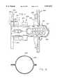
- FIG. 1is a top plan view of the foot care device of the present invention.
- FIG. 2is a bottom plan view of the foot care device shown in FIG. 1.
- FIG. 3is a side elevation view of the foot care device shown in FIG. 1.
- FIG. 4is a side elevation view of the foot care device shown in FIG. 1 including a partial cross-sectional view of the Achilles portion of the device.
- FIG. 5is a sectional view of the foot care device shown in FIG. 3 taken along line 5--5 of FIG. 3.
- FIG. 6is a sectional view of the foot care device shown in FIG. 3 taken along line 6--6 of FIG. 3.
- FIG. 7is a perspective view of the foot care device of the present invention as it appears partially secured in position about the foot, Achilles tendon, and leg of a person.
- FIG. 8is a partial bottom plan view of an alternative embodiment of the foot care device of the present invention including supplemental strap means.
- FIG. 9is a perspective view of the alternative embodiment of the present invention shown in FIG. 8, as it appears partially secured about the leg, ankle, and foot of a person.
- FIG. 10is a perspective view of the embodiment of the present invention of FIG. 8 showing an alternative method of securing the supplemental strap means.
- FIG. 11is a top plan view of an alternative embodiment of the foot care device of the present invention.
- FIG. 12is a cross sectional view of the foot care device of the present invention taken along lines 12--12.
- FIG. 13is a bottom plan view of the foot care device shown in FIG. 11.
- FIG. 14is a perspective view of the foot care device shown in FIG. 11.
- FIG. 15is an alternative cross-sectional view of the inflatable member of FIG. 1 taken along the lines 15--15.
- FIG. 1shows a top plan view of a foot care device 10 according to the present invention.
- Foot care device 10may be constructed of a lightweight cotton, gauze, paper or synthetic material which may be woven or non-woven material, or any other material which is breathable and suitable for use in a hospital, alternative care or home care environment.
- the materialmust be strong enough to be secured about the foot and leg of a patient, and capable of being comfortably placed in contact with the foot, ankle and leg of a patient.
- the selected materialshould minimize shear force on the patient's tissue and should provide adequate wicking characteristics such that moisture is drawn away from the skin of the lower leg and foot, keeping the foot and leg at a normal temperature. Further the material must be one of sufficient flexibility and pliability to conform readily to the shape of the patient's foot.
- an inflatable interior channel meansmay be formed within the device, and whereby the inflatable interior channel means may be inflated and air pressure may be maintained within the channel means.
- Foot care device 10comprises three interconnected and cooperating sections as major components: foot section 12, ankle section 9 and leg section 11.
- An inflatable interior channel 48extends throughout these three sections.
- Inflatable interior channel means 48is configured to form one or more air cushions which provide support to a patient's foot, ankle, or leg. (Best illustrated in FIGS. 3 and 4.) In other words, inflation of interior channel means 48 inflates foot cushioning portion 63, ankle support portion 61, and leg cushioning portion 62 of device 10 so as to form a soft, flexible supporting cushion around the lower leg, toe, and ankle areas of a patient's foot. Inflatable interior channel means 48 is constructed so as to readily conform to the anatomy of the foot of a patient in such a manner as to hold the foot securely and comfortably in a position which minimizes pressure on the heel. In this manner, formation of decubitus ulcers on the heel are substantially prevented.
- inflatable interior channel means 48interconnects foot section 12, ankle section 9 and leg section 11, and forms foot cushioning portion 63, ankle support portion 61 and leg cushioning portion 62 such that all three cushioning portions can be inflated through nozzle 45.
- inflatable interior channel means 48is inflated through nozzle 45, which may include a check valve, to a pressure which provides the desired support and comfort to a patient.
- Alternative embodimentsmay have different inflating configurations yet still remain within the scope of the present invention.
- Foot cushioning portion 63is preferably positioned to extend outwardly of the device past the toes of a patient such that contact between the patient's toes and objects in the patient's immediate vicinity, e.g., sheets and blankets of a hospital bed, is substantially prevented.
- foot section 12includes one or more foot strap means 2, a recessed foot portion 40, and in addition, partially includes heel opening 30.
- Recessed foot portion 40, non-inflated,may be provided with means 27, aperture, for exchanging air between the foot of a patient and the surrounding atmosphere.
- Foot strap means 2includes two elongated tabs, 15 and 16, one tab extending from each side of device 10.
- elongated tab 15is located on side A of device 10 and elongated tab 16 is located on side B of device 10.
- elongated tabs 15 and 16are adapted to include fastening means 22 and 23 respectively.
- Fastening means 22 and 23may comprise VelcroTM pieces but other known affixing means may be employed while remaining within the scope of the present invention.
- the proximal ends of elongated tabs 15 and 16include flared portions 90 and 91 which extend alongside foot section 12 in the direction of the toes of a patient such that foot section 12 and foot cushioning portion 63 will be brought into gentle but secure engagement with the foot of a patient when elongated tabs 15 and 16 are secured to short tabs 20 and 19. (Best illustrated in FIGS. 3 and 4.) As best illustrated in FIGS.
- elongated tabs 15 and 16are preferably affixed to foot section 12 along seam 95 on sides A and B respectively of device 10.
- Elongated tabs 15 and 16may be affixed to foot section 12 of device 10 by sewing, gluing or attaching them by other known means within seam 95 of device 10.
- elongated tabs 15 and 16may be formed as an integral part of device 10 during manufacture.
- Device 10is adapted to include a heel opening 30 interposed between foot section 12 and ankle section 9. Heel opening 30 is adapted to receive the heel of a patient, the heel being inserted therethrough, thereby permitting observation of the condition of the patient's heel without removing device 10.
- Ankle section 9includes means 13 for securing foot strap means 2.
- Means 13 for securing foot strap means 2includes two short tabs: side A short tab 20, and side B short tab 19.
- the distal ends of short tabs 20 and 19are adapted to include on their bottom facing surfaces (best illustrated in FIG. 2) means 4 and 5 for affixing elongated tabs 15 and 16 thereto.
- Means 4 and 5 for affixing elongated tabs 15 and 16are preferably VelcroTM pieces.
- other affixing meanswill be apparent to those skilled in the art and remain within the scope of the invention.
- short tab 20 and short tab 19are affixed to ankle section 9 of device 10 by sewing, gluing or attaching by other known means to seam 95 on sides A and B respectively of device 10.
- ankle support portion 61Also included in ankle section 9 is ankle support portion 61.
- Ankle support portion 61is effectively separated into two halves by Achilles crevice 46.
- Achilles crevice 46forms a recess in ankle support portion 61 which generally conforms to the Achilles tendon of a patient when the heel of the patient is inserted through heel opening 30.
- the remaining surface area of ankle support portion 61conforms to and supports the area of the patient's foot immediately surrounding the Achilles tendon and ankle, as best illustrated in FIG. 4.
- Leg section 11includes leg strap means 50, leg cushioning portion 62 and recessed leg portion 41.
- Recessed leg portion 41includes means for permitting air exchange 27.
- Recessed leg portion 41lies in the central area of leg section 11. Recessed leg portion 41 is uninflated and is substantially surrounded by leg cushioning portion 62.
- Leg strap means 50comprises two elongated rectangular tabs 52 and 53.
- Elongated rectangular tabs 52 and 53include affixing means 51 and 54 at their distal ends.
- Affixing means 51 and 54preferably comprise VelcroTM tabs configured so as to interlock with each other when leg strap means 50 is secured around the leg of a patient (as illustrated in FIGS. 3, 4, and 7).
- FIGS. 3 and 4illustrate device 10 as it appears secured about the foot 72, ankle 87 (shown in FIG. 4) and leg 73 of a patient.
- foot section 12is divided into a top section 99 and a bottom section 98 by seam 95.
- heel 71 of a patientis positioned in heel opening 30 (shown in FIG. 1) of device 10.
- Foot section 12 and leg section 11are folded toward one another until foot section 12 rests securely and comfortably against the foot 72 of the patient, while leg section 11 rests securely and comfortably against the leg 73 of the patient.
- Foot strap means 2are then affixed to means 13 for securing foot strap means 2.
- FIG. 7the latter is accomplished by first crossing one elongated tab, say 16, over the top of the foot 72 of the patient and toward fastening portion 4 of short tab 20, until fastening portion 23 of elongated tab 16 (best illustrated in FIG. 1) comes into contact with fastening portion 4 of short tab 20 (as best illustrated in FIG. 2). Fastening portion 23 of elongated tab 16 is then secured to fastening portion 4 of short tab 20. The action is subsequently repeated for elongated tab 15.
- Leg strap means 50is secured about the calf portion of the leg 73 of the patient.
- foot cushioning portion 63, ankle support portion 61, and leg cushioning portion 62are brought into gentle yet snug engagement with the sides of the foot 72, leg 73 and the ankle 87 of the patient.
- foot strap means 2being secured about the ankle of the patient, provides further stability to the patient's ankle. In this manner the ankle of the patient is held in advantageous alignment with the foot 72 and leg 73 of the patient.
- FIG. 6is a sectional view taken along lines 6--6 of FIG. 3.
- Achilles crevice 46provides pressure relief for Achilles tendon 70 of the patient.
- Ankle support portion 61which is inflated with air, provides support to both sides of Achilles tendon 70, allowing the tendon itself to project into Achilles crevice 46, thereby substantially limiting the contact between Achilles tendon 70 and device 10.
- FIG. 5is a sectional view taken along lines 5--5 of FIG. 3.
- FIG. 5shows leg cushioning means 62 as it supports leg 73 of a patient.
- Upper crevice 47provides pressure relief for portions of leg 73 of the patient.
- FIGS. 8, 9 and 10illustrate an alternative embodiment 100 of the device of the present invention.
- Device 100is similar to device 10 and like numerals are used to indicate like parts.
- device 100includes a supplemental strap means 180 (best illustrated in FIG. 8).
- Supplemental strap means 180provides additional support to hold and immobilize a patient's foot and lower leg. Such additional support is especially useful for patients suffering from a condition known as "foot drop" in which the angle between the sole of the foot and the axis of the leg is abnormally obtuse when the muscles are relaxed.
- Supplemental strap means 180comprises two elongated strips 181 and 182 which may be affixed at their distal ends to seam 195 of foot section 112 in the same manner as previously described for elongated tabs 15 and 16 of device 10.
- Elongated strips 181 and 182may be crossed over the foot 172 of a patient and affixed to short tabs (one shown) 105, thereby providing additional support to the foot 172 and ankle of a patient.
- elongated strips 181 and 182may be affixed to short tabs 104 and 105 in the manner shown in FIG. 10. That is, each elongated strip may be extended directly to the short tab located on the same side, without crossing over foot 172. This configuration supports the ankle in a manner which tends to hold the ankle in alignment with the foot and leg of the patient.
- FIG. 8is a bottom plan view of device 100 showing a preferred means for affixing elongated strips 182 and 181 to device 100.
- supplemental strap means 180comprises a single length of material, one end of which serves as elongated strip 181 and the other end of which serves as elongated strip 182.
- Supplemental strap 180is inserted through preformed slot 190 located on the bottom of recessed foot section 140 of device 100.
- FIG. 11shows an alternative embodiment 200 of the foot care device of the present invention.
- Like reference numeralsare used throughout FIG. 11 to indicate equivalent components to the embodiments shown in FIGS. 1-10.
- a foot strap meansis indicated at reference numeral 2
- equivalent foot strap meansare indicated at reference numeral 202.
- Device 200has additional features which allow device 200 to more readily conform to a wider range of foot sizes than the embodiments previously described herein.
- Device 200is similar to device 100 in that device 200 includes a supplemental strap means 180. However, device 200 differs from device 100 in some significant respects.
- device 100has a single means 13 for securing foot strap means 2. The same means 13 for securing foot strap means 2 may be used to secure supplemental strap means 180 of FIG. 8.
- device 200also includes means 213 for securing foot strap means 202
- device 200further includes means 313 for securing supplemental foot strap means 280.
- Means 213 and 313are similar in construction to means 13 and to each other. Means 213 is located in essentially the same position as means 13 of FIG. 1, and means 313 is located between means 213 and leg strap means 250.
- means 313 for securing supplemental strap means 280provides additional flexibility as to the placement of supplemental strap means 280.
- foot strap means 202may be secured to means 213 for securing foot strap means 202 as with the other embodiments.
- Supplemental foot strap means 280may be secured to means 313 for securing supplemental strap means 280. This feature allows device 200 to be conform to a variety of foot sizes and to varying patient needs.
- Elongated fastening strip 290which may be one of the adhering sides of a VelcroTM fastening device, extends along the bottom of foot section 212.
- Supplemental strap means 280is provided with the other adhering side of the VelcroTM fastener. Accordingly, supplemental strap means 280 may be affixed in a variety of positions along elongated fastening strip 290. In that manner supplemental strap means 280 may be positioned to secure foot section 212 comfortably about the foot of a patient, in conformity with the length of the patient's foot.
- a sponge-like material 99fills the interior channel means 48.
- the sponge material 99when shipped is preferably flat, and when it is to be used, the consumer opens the nozzle 45 and fills the sponge material 99 with air.
- the sponge material 99When filled by merely opening the nozzle 45, the sponge material 99 has the preferred air pressure. That air pressure, however can be added to or deflated to a desired alternative pressure by conventional inflation or deflation means.
Landscapes
- Health & Medical Sciences (AREA)
- Nursing (AREA)
- Orthopedic Medicine & Surgery (AREA)
- Engineering & Computer Science (AREA)
- Biomedical Technology (AREA)
- Heart & Thoracic Surgery (AREA)
- Vascular Medicine (AREA)
- Life Sciences & Earth Sciences (AREA)
- Animal Behavior & Ethology (AREA)
- General Health & Medical Sciences (AREA)
- Public Health (AREA)
- Veterinary Medicine (AREA)
- Orthopedics, Nursing, And Contraception (AREA)
- Nozzles (AREA)
Abstract
Description
Claims (22)
Priority Applications (1)
| Application Number | Priority Date | Filing Date | Title |
|---|---|---|---|
| US09/144,703US5957872A (en) | 1997-09-04 | 1998-09-01 | Heel care device and method |
Applications Claiming Priority (2)
| Application Number | Priority Date | Filing Date | Title |
|---|---|---|---|
| US5781797P | 1997-09-04 | 1997-09-04 | |
| US09/144,703US5957872A (en) | 1997-09-04 | 1998-09-01 | Heel care device and method |
Publications (1)
| Publication Number | Publication Date |
|---|---|
| US5957872Atrue US5957872A (en) | 1999-09-28 |
Family
ID=22012933
Family Applications (1)
| Application Number | Title | Priority Date | Filing Date |
|---|---|---|---|
| US09/144,703Expired - LifetimeUS5957872A (en) | 1997-09-04 | 1998-09-01 | Heel care device and method |
Country Status (5)
| Country | Link |
|---|---|
| US (1) | US5957872A (en) |
| CH (1) | CH694240A5 (en) |
| DE (1) | DE19882669B4 (en) |
| GB (1) | GB2346809B (en) |
| WO (1) | WO1999011204A1 (en) |
Cited By (44)
| Publication number | Priority date | Publication date | Assignee | Title |
|---|---|---|---|---|
| USD453969S1 (en) | 2001-04-09 | 2002-02-26 | Polymer Concepts, Inc. | Foot protector |
| US20020187332A1 (en)* | 1998-07-22 | 2002-12-12 | Flick Roland E. | Gelatinous composite article and construction |
| US20030028157A1 (en)* | 2001-07-13 | 2003-02-06 | Jusiak Joel T. | Support device with integrated pressure adjustment device and method of use |
| US6523201B1 (en)* | 1999-05-04 | 2003-02-25 | Eliza A. De Michele | Sleep support system |
| US6640810B1 (en) | 2001-06-22 | 2003-11-04 | Polymer Concepts, Inc. | Foot protector |
| US20030208848A1 (en)* | 2002-02-28 | 2003-11-13 | Flick Roland E. | Self-adjusting cushioning device |
| US6689079B2 (en) | 2001-07-13 | 2004-02-10 | Gaymar Industries, Inc. | Support device with pressure adjustment section and method of use |
| US6739001B2 (en) | 2001-04-27 | 2004-05-25 | Gaymar Industries, Inc. | Cushioning device including a restraint structure |
| US20040236258A1 (en)* | 2003-05-20 | 2004-11-25 | Michael Burns | Inflatable support, kit and method |
| US6878125B1 (en) | 2004-07-09 | 2005-04-12 | Robert Bentivegna | Inflatable support shoe for a foot cast |
| US20050145256A1 (en)* | 2003-12-24 | 2005-07-07 | Howard Mark E. | Orthopedic walker having a soft boot with a deformable insert |
| WO2005084136A2 (en) | 2004-03-10 | 2005-09-15 | R & D Supports | Immobilizing and supporting inflatable splint apparatus |
| US20060241541A1 (en)* | 2005-04-20 | 2006-10-26 | Sundaram Ravikumar | Therapeutic bandage for the heel of the foot |
| US20060247564A1 (en)* | 2005-05-02 | 2006-11-02 | Sundaram Ravikumar | Compression apparatus for applying localized pressure to an extremity |
| US20070095353A1 (en)* | 2005-10-27 | 2007-05-03 | Sundaram Ravikumar | Reconfigurable heel elevator |
| US20070161933A1 (en)* | 2005-10-27 | 2007-07-12 | Sundaram Ravikumar | Compression garment with heel elevation |
| WO2008032309A2 (en) | 2006-09-14 | 2008-03-20 | Ortho-Flex Ltd. | Inflatable splint |
| EP2140784A1 (en)* | 2008-07-03 | 2010-01-06 | Theo Kinsbergen | Pillow, packaging of the pillow and method for supporting parts of the body |
| USD608006S1 (en) | 2007-04-09 | 2010-01-12 | Tyco Healthcare Group Lp | Compression device |
| US7698765B2 (en) | 2004-04-30 | 2010-04-20 | Hill-Rom Services, Inc. | Patient support |
| US20100100018A1 (en)* | 2008-10-20 | 2010-04-22 | Breg, Inc. | Orthopedic walker boot having an inflatable bladder |
| USD618358S1 (en) | 2007-04-09 | 2010-06-22 | Tyco Healthcare Group Lp | Opening in an inflatable member for a pneumatic compression device |
| US7871387B2 (en) | 2004-02-23 | 2011-01-18 | Tyco Healthcare Group Lp | Compression sleeve convertible in length |
| WO2011025363A1 (en)* | 2009-07-07 | 2011-03-03 | Maxxcare B.V. | Heel protection device, buffer member and method |
| US20110087142A1 (en)* | 2005-10-27 | 2011-04-14 | Sun Scientific, Inc. | Compression garments with heel elevation |
| US8016779B2 (en) | 2007-04-09 | 2011-09-13 | Tyco Healthcare Group Lp | Compression device having cooling capability |
| US8021388B2 (en) | 2007-04-09 | 2011-09-20 | Tyco Healthcare Group Lp | Compression device with improved moisture evaporation |
| US8029450B2 (en) | 2007-04-09 | 2011-10-04 | Tyco Healthcare Group Lp | Breathable compression device |
| US8029451B2 (en) | 2005-12-12 | 2011-10-04 | Tyco Healthcare Group Lp | Compression sleeve having air conduits |
| US8034007B2 (en) | 2007-04-09 | 2011-10-11 | Tyco Healthcare Group Lp | Compression device with structural support features |
| US8070699B2 (en) | 2007-04-09 | 2011-12-06 | Tyco Healthcare Group Lp | Method of making compression sleeve with structural support features |
| US8109892B2 (en) | 2007-04-09 | 2012-02-07 | Tyco Healthcare Group Lp | Methods of making compression device with improved evaporation |
| US8114117B2 (en) | 2008-09-30 | 2012-02-14 | Tyco Healthcare Group Lp | Compression device with wear area |
| US8128584B2 (en) | 2007-04-09 | 2012-03-06 | Tyco Healthcare Group Lp | Compression device with S-shaped bladder |
| US8162861B2 (en) | 2007-04-09 | 2012-04-24 | Tyco Healthcare Group Lp | Compression device with strategic weld construction |
| US8235923B2 (en) | 2008-09-30 | 2012-08-07 | Tyco Healthcare Group Lp | Compression device with removable portion |
| US8506508B2 (en) | 2007-04-09 | 2013-08-13 | Covidien Lp | Compression device having weld seam moisture transfer |
| US8539647B2 (en) | 2005-07-26 | 2013-09-24 | Covidien Ag | Limited durability fastening for a garment |
| US20140031731A1 (en)* | 2012-07-26 | 2014-01-30 | Anna Waugh | Relating to a therapeutic foot support |
| US8652079B2 (en) | 2010-04-02 | 2014-02-18 | Covidien Lp | Compression garment having an extension |
| USD711000S1 (en) | 2011-09-26 | 2014-08-12 | Sun Scientific Inc. | Leg elevation apparatus |
| US9033906B2 (en) | 2010-08-12 | 2015-05-19 | Sun Scientific, Inc. | Therapeutic compression apparatus |
| US9205021B2 (en) | 2012-06-18 | 2015-12-08 | Covidien Lp | Compression system with vent cooling feature |
| US10751221B2 (en) | 2010-09-14 | 2020-08-25 | Kpr U.S., Llc | Compression sleeve with improved position retention |
Families Citing this family (9)
| Publication number | Priority date | Publication date | Assignee | Title |
|---|---|---|---|---|
| US6551280B1 (en) | 2000-06-30 | 2003-04-22 | Embro Corporation | Therapeutic device and system |
| DE102005037077B4 (en)* | 2004-08-07 | 2006-12-28 | Elfriede Linnemann | Heel and ankle protectors for decubitus prophylaxis |
| WO2011135078A1 (en)* | 2010-04-29 | 2011-11-03 | Decumed Aps | An inflatable and / or vaccumizable medical device |
| CA2772758C (en)* | 2011-03-29 | 2016-10-11 | Ehob Incorporated | Inflatable foot cushion |
| DE102011121301A1 (en)* | 2011-12-15 | 2013-06-20 | Bernd Schwerder | Device e.g. shoe, for e.g. preventing pressure points on foot of bedridden human, has pressure pad provided in edge area of sensitive regions to be protected, where device comprises soft and resilient material and positively encloses foot |
| DE202012101202U1 (en) | 2012-04-03 | 2012-04-27 | Eva-Maria Tiersch | Device for heel release |
| GB2536011B (en)* | 2015-03-03 | 2018-08-08 | Frontier Therapeutics Ltd | Limb support and limb support fastening arrangement |
| US12357488B2 (en) | 2020-10-14 | 2025-07-15 | Darco International, Inc. | Rear entry walker |
| DE102023122785A1 (en)* | 2023-08-24 | 2025-02-27 | Lohmann & Rauscher Gmbh | padding to relieve pressure on a wound |
Citations (15)
| Publication number | Priority date | Publication date | Assignee | Title |
|---|---|---|---|---|
| US3345654A (en)* | 1966-03-21 | 1967-10-10 | Ruth I Noble | Drop foot and heel guard for bed patients |
| US3351055A (en)* | 1963-11-26 | 1967-11-07 | Jobst Institute | Pressure bandage-splint and method of forming same |
| US4266298A (en)* | 1980-01-31 | 1981-05-12 | Marlene S. Mindey | Inflatable heel protector |
| US4730610A (en)* | 1985-05-06 | 1988-03-15 | Graebe Robert H | Foot and elbow cushion device |
| US5020523A (en)* | 1990-10-09 | 1991-06-04 | Capra Resources, Inc. | Foot and leg splint device |
| US5328445A (en)* | 1993-01-15 | 1994-07-12 | Ehob, Inc. | Inflatable foot cushion |
| US5372576A (en)* | 1993-06-10 | 1994-12-13 | Orthosis Corrective Systems Corp. | Therapeutic foot orthosis |
| US5389065A (en)* | 1993-06-15 | 1995-02-14 | Aircast, Inc. | Ankle brace with ATF compression |
| US5460600A (en)* | 1994-03-24 | 1995-10-24 | Select Medical Products | Universal foot splint |
| US5489259A (en)* | 1993-10-27 | 1996-02-06 | Sundance Enterprises, Inc. | Pressure-normalizing single-chambered static pressure device for supporting and protecting a body extremity |
| US5571077A (en)* | 1994-10-18 | 1996-11-05 | Lake Medical Products, Inc. | Self-supporting foot orthosis with pivotally mounted cover |
| US5577998A (en)* | 1995-02-03 | 1996-11-26 | Aircast, Incorporated | Walking brace |
| US5603690A (en)* | 1989-11-29 | 1997-02-18 | South Glamorgan Health Authority | Inflatable supports |
| US5613941A (en)* | 1992-09-24 | 1997-03-25 | Innovative Footwear Corporation | Joint support apparatus |
| US5833639A (en)* | 1995-10-27 | 1998-11-10 | Johnson & Johnson Professional, Inc. | Short leg walker |
Family Cites Families (2)
| Publication number | Priority date | Publication date | Assignee | Title |
|---|---|---|---|---|
| US5277695A (en)* | 1991-11-08 | 1994-01-11 | Aircast, Inc. | Adjustable ankle compress |
| US5378224A (en)* | 1993-06-09 | 1995-01-03 | Billotti; Joseph D. | Method for supporting body joints and brace therefor |
- 1998
- 1998-09-01USUS09/144,703patent/US5957872A/ennot_activeExpired - Lifetime
- 1998-09-04CHCH00455/00Apatent/CH694240A5/ennot_activeIP Right Cessation
- 1998-09-04GBGB0005368Apatent/GB2346809B/ennot_activeExpired - Lifetime
- 1998-09-04WOPCT/US1998/018391patent/WO1999011204A1/enactiveApplication Filing
- 1998-09-04DEDE19882669Tpatent/DE19882669B4/ennot_activeExpired - Lifetime
Patent Citations (16)
| Publication number | Priority date | Publication date | Assignee | Title |
|---|---|---|---|---|
| US3351055A (en)* | 1963-11-26 | 1967-11-07 | Jobst Institute | Pressure bandage-splint and method of forming same |
| US3345654A (en)* | 1966-03-21 | 1967-10-10 | Ruth I Noble | Drop foot and heel guard for bed patients |
| US4266298A (en)* | 1980-01-31 | 1981-05-12 | Marlene S. Mindey | Inflatable heel protector |
| US4266298B1 (en)* | 1980-01-31 | 1996-05-21 | Mindey Marlene S | Inflatable heel protector |
| US4730610A (en)* | 1985-05-06 | 1988-03-15 | Graebe Robert H | Foot and elbow cushion device |
| US5603690A (en)* | 1989-11-29 | 1997-02-18 | South Glamorgan Health Authority | Inflatable supports |
| US5020523A (en)* | 1990-10-09 | 1991-06-04 | Capra Resources, Inc. | Foot and leg splint device |
| US5613941A (en)* | 1992-09-24 | 1997-03-25 | Innovative Footwear Corporation | Joint support apparatus |
| US5328445A (en)* | 1993-01-15 | 1994-07-12 | Ehob, Inc. | Inflatable foot cushion |
| US5372576A (en)* | 1993-06-10 | 1994-12-13 | Orthosis Corrective Systems Corp. | Therapeutic foot orthosis |
| US5389065A (en)* | 1993-06-15 | 1995-02-14 | Aircast, Inc. | Ankle brace with ATF compression |
| US5489259A (en)* | 1993-10-27 | 1996-02-06 | Sundance Enterprises, Inc. | Pressure-normalizing single-chambered static pressure device for supporting and protecting a body extremity |
| US5460600A (en)* | 1994-03-24 | 1995-10-24 | Select Medical Products | Universal foot splint |
| US5571077A (en)* | 1994-10-18 | 1996-11-05 | Lake Medical Products, Inc. | Self-supporting foot orthosis with pivotally mounted cover |
| US5577998A (en)* | 1995-02-03 | 1996-11-26 | Aircast, Incorporated | Walking brace |
| US5833639A (en)* | 1995-10-27 | 1998-11-10 | Johnson & Johnson Professional, Inc. | Short leg walker |
Cited By (77)
| Publication number | Priority date | Publication date | Assignee | Title |
|---|---|---|---|---|
| US6843873B2 (en) | 1998-07-22 | 2005-01-18 | Gaymar Industries, Inc. | Method of making a gelatinous composite |
| US20020187332A1 (en)* | 1998-07-22 | 2002-12-12 | Flick Roland E. | Gelatinous composite article and construction |
| US6767621B2 (en) | 1998-07-22 | 2004-07-27 | Gaymar Industries, Inc. | Gelatinous composite article and construction |
| US6523201B1 (en)* | 1999-05-04 | 2003-02-25 | Eliza A. De Michele | Sleep support system |
| USD453969S1 (en) | 2001-04-09 | 2002-02-26 | Polymer Concepts, Inc. | Foot protector |
| US6739001B2 (en) | 2001-04-27 | 2004-05-25 | Gaymar Industries, Inc. | Cushioning device including a restraint structure |
| US6640810B1 (en) | 2001-06-22 | 2003-11-04 | Polymer Concepts, Inc. | Foot protector |
| US20030028157A1 (en)* | 2001-07-13 | 2003-02-06 | Jusiak Joel T. | Support device with integrated pressure adjustment device and method of use |
| US6689079B2 (en) | 2001-07-13 | 2004-02-10 | Gaymar Industries, Inc. | Support device with pressure adjustment section and method of use |
| WO2003005935A3 (en)* | 2001-07-13 | 2004-03-18 | Gaymar Ind Inc | Support device with pressure adjustment section and method of use |
| US6813790B2 (en) | 2002-02-28 | 2004-11-09 | Gaymar Industries, Inc. | Self-adjusting cushioning device |
| US20030208848A1 (en)* | 2002-02-28 | 2003-11-13 | Flick Roland E. | Self-adjusting cushioning device |
| US20040236258A1 (en)* | 2003-05-20 | 2004-11-25 | Michael Burns | Inflatable support, kit and method |
| US20050145256A1 (en)* | 2003-12-24 | 2005-07-07 | Howard Mark E. | Orthopedic walker having a soft boot with a deformable insert |
| US7871387B2 (en) | 2004-02-23 | 2011-01-18 | Tyco Healthcare Group Lp | Compression sleeve convertible in length |
| WO2005084136A2 (en) | 2004-03-10 | 2005-09-15 | R & D Supports | Immobilizing and supporting inflatable splint apparatus |
| US20050203451A1 (en)* | 2004-03-10 | 2005-09-15 | Daniel Reis | Immobilizing and supporting inflatable splint apparatus |
| WO2005084136A3 (en)* | 2004-03-10 | 2005-12-22 | R & D Supports | Immobilizing and supporting inflatable splint apparatus |
| US8142378B2 (en) | 2004-03-10 | 2012-03-27 | Daniel Reis | Immobilizing and supporting inflatable splint apparatus |
| US20080004555A1 (en)* | 2004-03-10 | 2008-01-03 | R & D Supports | Immobilizing and Supporting Inflatable Splint Apparatus |
| US7698765B2 (en) | 2004-04-30 | 2010-04-20 | Hill-Rom Services, Inc. | Patient support |
| US8146191B2 (en) | 2004-04-30 | 2012-04-03 | Hill-Rom Services, Inc. | Patient support |
| US6878125B1 (en) | 2004-07-09 | 2005-04-12 | Robert Bentivegna | Inflatable support shoe for a foot cast |
| US20060241541A1 (en)* | 2005-04-20 | 2006-10-26 | Sundaram Ravikumar | Therapeutic bandage for the heel of the foot |
| US7850629B2 (en) | 2005-05-02 | 2010-12-14 | Sundaram Ravikumar | Compression apparatus for applying localized pressure to an extremity |
| US20060247564A1 (en)* | 2005-05-02 | 2006-11-02 | Sundaram Ravikumar | Compression apparatus for applying localized pressure to an extremity |
| US8539647B2 (en) | 2005-07-26 | 2013-09-24 | Covidien Ag | Limited durability fastening for a garment |
| US9364037B2 (en) | 2005-07-26 | 2016-06-14 | Covidien Ag | Limited durability fastening for a garment |
| US8216165B2 (en) | 2005-10-27 | 2012-07-10 | Sundaram Ravikumar | Compression garments with heel elevation |
| US20070161933A1 (en)* | 2005-10-27 | 2007-07-12 | Sundaram Ravikumar | Compression garment with heel elevation |
| US20070095353A1 (en)* | 2005-10-27 | 2007-05-03 | Sundaram Ravikumar | Reconfigurable heel elevator |
| US7909787B2 (en) | 2005-10-27 | 2011-03-22 | Sundaram Ravikumar | Reconfigurable heel elevator |
| US20110087142A1 (en)* | 2005-10-27 | 2011-04-14 | Sun Scientific, Inc. | Compression garments with heel elevation |
| US7967766B2 (en) | 2005-10-27 | 2011-06-28 | Sundaram Ravikumar | Compression garment with heel elevation |
| US8079970B2 (en) | 2005-12-12 | 2011-12-20 | Tyco Healthcare Group Lp | Compression sleeve having air conduits formed by a textured surface |
| US8029451B2 (en) | 2005-12-12 | 2011-10-04 | Tyco Healthcare Group Lp | Compression sleeve having air conduits |
| WO2008032309A3 (en)* | 2006-09-14 | 2008-05-02 | R & D Supports Ltd | Inflatable splint |
| WO2008032309A2 (en) | 2006-09-14 | 2008-03-20 | Ortho-Flex Ltd. | Inflatable splint |
| US20090177132A1 (en)* | 2006-09-14 | 2009-07-09 | Ortho-Flex Ltd. | Inflatable Splint |
| US8016778B2 (en) | 2007-04-09 | 2011-09-13 | Tyco Healthcare Group Lp | Compression device with improved moisture evaporation |
| US8597215B2 (en) | 2007-04-09 | 2013-12-03 | Covidien Lp | Compression device with structural support features |
| US8029450B2 (en) | 2007-04-09 | 2011-10-04 | Tyco Healthcare Group Lp | Breathable compression device |
| US8016779B2 (en) | 2007-04-09 | 2011-09-13 | Tyco Healthcare Group Lp | Compression device having cooling capability |
| US8034007B2 (en) | 2007-04-09 | 2011-10-11 | Tyco Healthcare Group Lp | Compression device with structural support features |
| US8070699B2 (en) | 2007-04-09 | 2011-12-06 | Tyco Healthcare Group Lp | Method of making compression sleeve with structural support features |
| US9808395B2 (en) | 2007-04-09 | 2017-11-07 | Covidien Lp | Compression device having cooling capability |
| US8109892B2 (en) | 2007-04-09 | 2012-02-07 | Tyco Healthcare Group Lp | Methods of making compression device with improved evaporation |
| US9387146B2 (en) | 2007-04-09 | 2016-07-12 | Covidien Lp | Compression device having weld seam moisture transfer |
| US8128584B2 (en) | 2007-04-09 | 2012-03-06 | Tyco Healthcare Group Lp | Compression device with S-shaped bladder |
| USD618358S1 (en) | 2007-04-09 | 2010-06-22 | Tyco Healthcare Group Lp | Opening in an inflatable member for a pneumatic compression device |
| US9114052B2 (en) | 2007-04-09 | 2015-08-25 | Covidien Lp | Compression device with strategic weld construction |
| US8162861B2 (en) | 2007-04-09 | 2012-04-24 | Tyco Healthcare Group Lp | Compression device with strategic weld construction |
| US9107793B2 (en) | 2007-04-09 | 2015-08-18 | Covidien Lp | Compression device with structural support features |
| US9084713B2 (en) | 2007-04-09 | 2015-07-21 | Covidien Lp | Compression device having cooling capability |
| US8992449B2 (en) | 2007-04-09 | 2015-03-31 | Covidien Lp | Method of making compression sleeve with structural support features |
| US8740828B2 (en) | 2007-04-09 | 2014-06-03 | Covidien Lp | Compression device with improved moisture evaporation |
| US8506508B2 (en) | 2007-04-09 | 2013-08-13 | Covidien Lp | Compression device having weld seam moisture transfer |
| USD608006S1 (en) | 2007-04-09 | 2010-01-12 | Tyco Healthcare Group Lp | Compression device |
| US8021388B2 (en) | 2007-04-09 | 2011-09-20 | Tyco Healthcare Group Lp | Compression device with improved moisture evaporation |
| US8622942B2 (en) | 2007-04-09 | 2014-01-07 | Covidien Lp | Method of making compression sleeve with structural support features |
| US8721575B2 (en) | 2007-04-09 | 2014-05-13 | Covidien Lp | Compression device with s-shaped bladder |
| US10137052B2 (en) | 2008-04-07 | 2018-11-27 | Kpr U.S., Llc | Compression device with wear area |
| EP2140784A1 (en)* | 2008-07-03 | 2010-01-06 | Theo Kinsbergen | Pillow, packaging of the pillow and method for supporting parts of the body |
| US8235923B2 (en) | 2008-09-30 | 2012-08-07 | Tyco Healthcare Group Lp | Compression device with removable portion |
| US8632840B2 (en) | 2008-09-30 | 2014-01-21 | Covidien Lp | Compression device with wear area |
| US8114117B2 (en) | 2008-09-30 | 2012-02-14 | Tyco Healthcare Group Lp | Compression device with wear area |
| US20100100018A1 (en)* | 2008-10-20 | 2010-04-22 | Breg, Inc. | Orthopedic walker boot having an inflatable bladder |
| US8251932B2 (en) | 2008-10-20 | 2012-08-28 | Breg, Inc. | Orthopedic walker boot having an inflatable bladder |
| US20100100020A1 (en)* | 2008-10-20 | 2010-04-22 | Breg, Inc. | Orthopedic walker boot having a removable heel plate |
| US8251936B2 (en) | 2008-10-20 | 2012-08-28 | Breg, Inc. | Orthopedic walker boot having a removable heel plate |
| WO2011025363A1 (en)* | 2009-07-07 | 2011-03-03 | Maxxcare B.V. | Heel protection device, buffer member and method |
| US8652079B2 (en) | 2010-04-02 | 2014-02-18 | Covidien Lp | Compression garment having an extension |
| US9033906B2 (en) | 2010-08-12 | 2015-05-19 | Sun Scientific, Inc. | Therapeutic compression apparatus |
| US10751221B2 (en) | 2010-09-14 | 2020-08-25 | Kpr U.S., Llc | Compression sleeve with improved position retention |
| USD711000S1 (en) | 2011-09-26 | 2014-08-12 | Sun Scientific Inc. | Leg elevation apparatus |
| US9205021B2 (en) | 2012-06-18 | 2015-12-08 | Covidien Lp | Compression system with vent cooling feature |
| US20140031731A1 (en)* | 2012-07-26 | 2014-01-30 | Anna Waugh | Relating to a therapeutic foot support |
Also Published As
| Publication number | Publication date |
|---|---|
| DE19882669T1 (en) | 2000-08-03 |
| GB2346809A (en) | 2000-08-23 |
| WO1999011204A1 (en) | 1999-03-11 |
| GB2346809B (en) | 2002-04-24 |
| DE19882669B4 (en) | 2010-04-22 |
| CH694240A5 (en) | 2004-10-15 |
| GB0005368D0 (en) | 2000-04-26 |
Similar Documents
| Publication | Publication Date | Title |
|---|---|---|
| US5957872A (en) | Heel care device and method | |
| US6375633B1 (en) | Heel care device and method | |
| US6793639B2 (en) | Pelvic splint and associated method | |
| US5289828A (en) | Abduction pillow for orthopedic support | |
| US5827211A (en) | Ankle-foot-heel protective orthotic boot | |
| US4266298A (en) | Inflatable heel protector | |
| US6689079B2 (en) | Support device with pressure adjustment section and method of use | |
| JP2870949B2 (en) | Limb sleeve | |
| US6260221B1 (en) | Medical apparatus for the treatment and prevention of heel decubitus | |
| WO1998019638A1 (en) | Pneumatic achilles wrap | |
| WO1998019638A9 (en) | Pneumatic achilles wrap | |
| US4971044A (en) | Method of manufacturing a compressible sleeve | |
| EP0388200B1 (en) | Full length compressible sleeve | |
| US4263905A (en) | Decubitous boot | |
| US4926884A (en) | Method and means for preventing skin abrasions for patients having legs substantially locked in juxtaposition | |
| US6200284B1 (en) | Gelastic heel care device and method | |
| US2723663A (en) | Traction cuff | |
| EP2079408B1 (en) | Inflatable splint | |
| US4399815A (en) | Pneumatic therapeutic heel and ankle guard | |
| US5465736A (en) | Method and means for preventing skin abrasions for patients having legs substantially locked in juxtaposition | |
| PT824016E (en) | DEVICE FOR THE TREATMENT OF SCISSORING TISSUE | |
| US20060173393A1 (en) | Inflatable splint for stabilisation of the ankle | |
| US2324619A (en) | Bed comforter | |
| US20190314184A1 (en) | Medical Rehabilitation Boot And Method For Preventing Heel Decubitus | |
| CN119184947B (en) | Knee encircles cold compress device |
Legal Events
| Date | Code | Title | Description |
|---|---|---|---|
| AS | Assignment | Owner name:GAYMAR INDUSTRIES, INC., NEW YORK Free format text:ASSIGNMENT OF ASSIGNORS INTEREST;ASSIGNOR:FLICK, ROLAND E.;REEL/FRAME:009448/0074 Effective date:19980831 | |
| STCF | Information on status: patent grant | Free format text:PATENTED CASE | |
| AS | Assignment | Owner name:ANTARES CAPITAL CORPORATION, AS COLLATERAL AGENT, Free format text:SECURITY INTEREST;ASSIGNOR:GAYMAR INDUSTRIES, INC.;REEL/FRAME:011575/0778 Effective date:20010118 | |
| AS | Assignment | Owner name:ANTARES CAPITAL CORPORATION, AS COLLATERAL AGENT, Free format text:SECURITY AGREEMENT;ASSIGNOR:GAYMAR INDUSTRIES, INC.;REEL/FRAME:013791/0180 Effective date:20030214 | |
| AS | Assignment | Owner name:GAYMAR INDUSTRIES, INC., NEW YORK Free format text:RELEASE AND REASSIGNMENT;ASSIGNOR:ANTARES CAPITAL CORPORATION, AS COLLATERAL AGENT;REEL/FRAME:013835/0269 Effective date:20030214 | |
| FPAY | Fee payment | Year of fee payment:4 | |
| FPAY | Fee payment | Year of fee payment:8 | |
| AS | Assignment | Owner name:GENERAL ELECTRIC CAPITAL CORPORATION, AS COLLATERA Free format text:NOTICE OF CHANGE OF COLLATERAL AGENT- PATENT SECURITY AGREEMENT;ASSIGNOR:ANTARES CAPITAL CORPORATION, AS COLLATERAL AGENT;REEL/FRAME:022473/0593 Effective date:20090330 | |
| AS | Assignment | Owner name:GAYMAR INDUSTRIES, INC., NEW YORK Free format text:RELEASE BY SECURED PARTY;ASSIGNORS:GENERAL ELECTRIC CAPITAL CORPORATION;ANTARES CAPITAL CORPORATION;REEL/FRAME:025114/0273 Effective date:20101001 | |
| FEPP | Fee payment procedure | Free format text:PAT HOLDER NO LONGER CLAIMS SMALL ENTITY STATUS, ENTITY STATUS SET TO UNDISCOUNTED (ORIGINAL EVENT CODE: STOL); ENTITY STATUS OF PATENT OWNER: LARGE ENTITY | |
| FEPP | Fee payment procedure | Free format text:ENTITY STATUS SET TO UNDISCOUNTED (ORIGINAL EVENT CODE: BIG.); ENTITY STATUS OF PATENT OWNER: LARGE ENTITY | |
| FPAY | Fee payment | Year of fee payment:12 | |
| AS | Assignment | Owner name:STRYKER CORPORATION, MICHIGAN Free format text:ASSIGNMENT OF ASSIGNORS INTEREST;ASSIGNOR:GAYMAR INDUSTRIES, INC.;REEL/FRAME:027025/0001 Effective date:20110819 | |
| FEPP | Fee payment procedure | Free format text:PAYOR NUMBER ASSIGNED (ORIGINAL EVENT CODE: ASPN); ENTITY STATUS OF PATENT OWNER: LARGE ENTITY |