US5957539A - Process for excavating a cavity in a thin salt layer - Google Patents
Process for excavating a cavity in a thin salt layerDownload PDFInfo
- Publication number
- US5957539A US5957539AUS08/895,983US89598397AUS5957539AUS 5957539 AUS5957539 AUS 5957539AUS 89598397 AUS89598397 AUS 89598397AUS 5957539 AUS5957539 AUS 5957539A
- Authority
- US
- United States
- Prior art keywords
- void
- tunnel
- communication space
- duct
- injection
- Prior art date
- Legal status (The legal status is an assumption and is not a legal conclusion. Google has not performed a legal analysis and makes no representation as to the accuracy of the status listed.)
- Expired - Lifetime
Links
Images

Classifications
- E—FIXED CONSTRUCTIONS
- E21—EARTH OR ROCK DRILLING; MINING
- E21F—SAFETY DEVICES, TRANSPORT, FILLING-UP, RESCUE, VENTILATION, OR DRAINING IN OR OF MINES OR TUNNELS
- E21F17/00—Methods or devices for use in mines or tunnels, not covered elsewhere
- E21F17/16—Modification of mine passages or chambers for storage purposes, especially for liquids or gases
- E—FIXED CONSTRUCTIONS
- E21—EARTH OR ROCK DRILLING; MINING
- E21B—EARTH OR ROCK DRILLING; OBTAINING OIL, GAS, WATER, SOLUBLE OR MELTABLE MATERIALS OR A SLURRY OF MINERALS FROM WELLS
- E21B43/00—Methods or apparatus for obtaining oil, gas, water, soluble or meltable materials or a slurry of minerals from wells
- E21B43/28—Dissolving minerals other than hydrocarbons, e.g. by an alkaline or acid leaching agent
Definitions
- the inventionconcerns a process for excavating by dissolution, an underground cavity in a thin salt layer, for example an underground salt layer.
- the object of the inventionis to obtain, after excavation, a cavity for the storage of a fluid, in particular natural gas, in a salt cavern obtained after the dissolution process.
- the dissolution processhas to be controlled in order to ensure that the final cavity has a mechanically stable shape.
- the inventionconcerns a process for developing a tunnel-shaped cavern in such a th in salt layer.
- the blind tunnelextends between an open end and a closed end
- the blind tunnelcommunicates via its open end with the communication space
- the inventionproposes that, to excavate the cavity, the blind tunnel also be excavated by circulating the solvent in this tunnel, making the solvent pass into the tunnel via its open end from the communication space and recovering the resultant brine so that it can be extracted therefrom.
- a blind tunnelis a tunnel which is distinct from the communication space and has a single end communicating with said space.
- voiddesignates the initial state of a space or tunnel (before the solvent dissolves the salt). It could correspond to a preliminary borehole.
- a variant likewise enabling the dissolution action in the blind tunnel to be improvedconsists in:
- the injection and extraction ductsare produced at a spacing from each other;
- an elongate partis provided in the communication space void
- the inventionproposes disposing the inject ion and extraction ducts substantially coaxially, such that one of these ducts is located in the centre and is surrounded by the other, at least over part of its axial length. In this case only one hole has to be excavated in order to produce the two ducts.
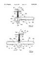
- FIG. 2shows in section a first cavity form obtained from the void of FIG. 1 after excavation by dissolution of some of the salt present in the salt layer;
- FIG. 3shows in section a second cavity form obtained after excavation by dissolution of some of the salt present in the salt layer
- FIG. 1shows a salt layer 1 in stratified form and comprised between two layers of other minerals present in the ground 10.
- An injection duct 16 and an extraction duct 18are disposed in two shafts, after excavation thereof, substantially vertically between ground level and a cavity void la excavated in the salt layer 1.
- These ductshave one end 16a, 18b located at ground level and one end 16b, 18a located in the cavity void 1a.
- the ends 16b, 18a located in the cavity void 1aare connected by a communication space void 4.
- the communication space void 4has been drilled proceeding from the duct 18.
- the drilling axis 13is shown in broken lines.
- the diameter of the voidis approximately 6 cm and preferably less than 10 cm.
- the communication space void 4has an elongate, substantially rectilinear and horizontal part 4c between an end part 4b, connected to the extraction duct 18, and a further end part 4a surrounding the injection duct 16 over part of its length, in the vicinity of its end 16b which forms a point of injection into the cavity.
- the injected watercirculates from the end 14a of the communication space towards the elongate part 14c of the communication space 14 and the blind tunnel 12.
- the wateris not introduced owing to the pressure at which it is injected into the blind tunnel but under the effect of a flow created by the dissolution of the salt.
- the brinepasses from the blind tunnel 12 towards the elongate horizontal part 14c of the communication space 14, such that the brine formed in the blind tunnel is recovered in the communication space so as to be extracted therefrom.
- the blind tunnel 12communicates with the communication space 14 solely via the open end, which enables the blind tunnel to be flooded with water by introducing water thereinto and recovering the brine formed by dissolution of the salt in the blind tunnel.
- FIG. 3the parts corresponding to those in FIG. 2 are denoted by the same number increased by 10.
- This Figureessentially differs from FIG. 2 in that the injection duct 26 and extraction duct 28 are coaxial. Since the injection duct 26 descends the furthest in the cavity 21a, it is located on the interior and the extraction duct 28 is located on the exterior. The extraction duct 28 surrounds the injection duct over the major part of its length.
- the communication spacehere no longer has a horizontal elongate part and is produced entirely around the injection duct 26 between the ends 26b, 28a of the injection and extraction ducts.
- the communication space voidcan easily be drilled at the same time as the extraction duct is drilled.
- the axis 23 of the blind tunnel voidis shown in broken lines.
- the water injected via the injection point 36brises since it is less dense than the brine present in the cavity and since the injection point is located below the open ends 32a, 42a of the blind holes.
- the wateris then distributed between the various blind tunnels and excavates them, becoming charged with salt as it does so.
- the resultant brinethen tends to descend in the end 34a of the communication space, as illustrated by the arrows 35c.
- the flow 35a of injected waterguides the brine towards the end 38a of the extraction duct 38, as illustrated by the arrows 35b.
- the brineis then extracted via the extraction duct 38.
Landscapes
- Engineering & Computer Science (AREA)
- Mining & Mineral Resources (AREA)
- Life Sciences & Earth Sciences (AREA)
- Geology (AREA)
- General Life Sciences & Earth Sciences (AREA)
- Geochemistry & Mineralogy (AREA)
- Physics & Mathematics (AREA)
- Environmental & Geological Engineering (AREA)
- Fluid Mechanics (AREA)
- Excavating Of Shafts Or Tunnels (AREA)
Abstract
Description
Claims (9)
Applications Claiming Priority (4)
| Application Number | Priority Date | Filing Date | Title |
|---|---|---|---|
| FR9609104AFR2751374B1 (en) | 1996-07-19 | 1996-07-19 | PROCESS FOR EXCAVATING A CAVITY IN A LOW-THICKNESS SALT MINE |
| FR9609104 | 1996-07-19 | ||
| EP97401582AEP0819834B1 (en) | 1996-07-19 | 1997-07-03 | Method for making a cavity in a thin-walled salt mine |
| FR97401582 | 1997-07-03 |
Publications (1)
| Publication Number | Publication Date |
|---|---|
| US5957539Atrue US5957539A (en) | 1999-09-28 |
Family
ID=26147846
Family Applications (1)
| Application Number | Title | Priority Date | Filing Date |
|---|---|---|---|
| US08/895,983Expired - LifetimeUS5957539A (en) | 1996-07-19 | 1997-07-17 | Process for excavating a cavity in a thin salt layer |
Country Status (1)
| Country | Link |
|---|---|
| US (1) | US5957539A (en) |
Cited By (50)
| Publication number | Priority date | Publication date | Assignee | Title |
|---|---|---|---|---|
| US6280000B1 (en) | 1998-11-20 | 2001-08-28 | Joseph A. Zupanick | Method for production of gas from a coal seam using intersecting well bores |
| US6412556B1 (en) | 2000-08-03 | 2002-07-02 | Cdx Gas, Inc. | Cavity positioning tool and method |
| US6425448B1 (en) | 2001-01-30 | 2002-07-30 | Cdx Gas, L.L.P. | Method and system for accessing subterranean zones from a limited surface area |
| US6454000B1 (en) | 1999-11-19 | 2002-09-24 | Cdx Gas, Llc | Cavity well positioning system and method |
| US6516616B2 (en) | 2001-03-12 | 2003-02-11 | Pomfret Storage Comapny, Llc | Storage of energy producing fluids and process thereof |
| US6598686B1 (en) | 1998-11-20 | 2003-07-29 | Cdx Gas, Llc | Method and system for enhanced access to a subterranean zone |
| US20030150213A1 (en)* | 2001-03-12 | 2003-08-14 | Carver Calvin R. | Storage of energy producing fluids and process thereof |
| US6662870B1 (en) | 2001-01-30 | 2003-12-16 | Cdx Gas, L.L.C. | Method and system for accessing subterranean deposits from a limited surface area |
| US6679322B1 (en) | 1998-11-20 | 2004-01-20 | Cdx Gas, Llc | Method and system for accessing subterranean deposits from the surface |
| US6681855B2 (en) | 2001-10-19 | 2004-01-27 | Cdx Gas, L.L.C. | Method and system for management of by-products from subterranean zones |
| US6708764B2 (en) | 2002-07-12 | 2004-03-23 | Cdx Gas, L.L.C. | Undulating well bore |
| US6725922B2 (en) | 2002-07-12 | 2004-04-27 | Cdx Gas, Llc | Ramping well bores |
| US6848508B2 (en) | 2001-10-30 | 2005-02-01 | Cdx Gas, Llc | Slant entry well system and method |
| US6942030B2 (en) | 2002-09-12 | 2005-09-13 | Cdx Gas, Llc | Three-dimensional well system for accessing subterranean zones |
| US6964308B1 (en) | 2002-10-08 | 2005-11-15 | Cdx Gas, Llc | Method of drilling lateral wellbores from a slant well without utilizing a whipstock |
| US6988548B2 (en) | 2002-10-03 | 2006-01-24 | Cdx Gas, Llc | Method and system for removing fluid from a subterranean zone using an enlarged cavity |
| US6991047B2 (en) | 2002-07-12 | 2006-01-31 | Cdx Gas, Llc | Wellbore sealing system and method |
| US6991048B2 (en) | 2002-07-12 | 2006-01-31 | Cdx Gas, Llc | Wellbore plug system and method |
| US7025154B2 (en) | 1998-11-20 | 2006-04-11 | Cdx Gas, Llc | Method and system for circulating fluid in a well system |
| US7073595B2 (en) | 2002-09-12 | 2006-07-11 | Cdx Gas, Llc | Method and system for controlling pressure in a dual well system |
| US7100687B2 (en) | 2003-11-17 | 2006-09-05 | Cdx Gas, Llc | Multi-purpose well bores and method for accessing a subterranean zone from the surface |
| US7134494B2 (en) | 2003-06-05 | 2006-11-14 | Cdx Gas, Llc | Method and system for recirculating fluid in a well system |
| US7163063B2 (en) | 2003-11-26 | 2007-01-16 | Cdx Gas, Llc | Method and system for extraction of resources from a subterranean well bore |
| US7207390B1 (en) | 2004-02-05 | 2007-04-24 | Cdx Gas, Llc | Method and system for lining multilateral wells |
| US7207395B2 (en) | 2004-01-30 | 2007-04-24 | Cdx Gas, Llc | Method and system for testing a partially formed hydrocarbon well for evaluation and well planning refinement |
| US7222670B2 (en) | 2004-02-27 | 2007-05-29 | Cdx Gas, Llc | System and method for multiple wells from a common surface location |
| US7264048B2 (en) | 2003-04-21 | 2007-09-04 | Cdx Gas, Llc | Slot cavity |
| US7299864B2 (en) | 2004-12-22 | 2007-11-27 | Cdx Gas, Llc | Adjustable window liner |
| US7353877B2 (en) | 2004-12-21 | 2008-04-08 | Cdx Gas, Llc | Accessing subterranean resources by formation collapse |
| US7360595B2 (en) | 2002-05-08 | 2008-04-22 | Cdx Gas, Llc | Method and system for underground treatment of materials |
| US7373984B2 (en) | 2004-12-22 | 2008-05-20 | Cdx Gas, Llc | Lining well bore junctions |
| US7419223B2 (en) | 2003-11-26 | 2008-09-02 | Cdx Gas, Llc | System and method for enhancing permeability of a subterranean zone at a horizontal well bore |
| US7571771B2 (en) | 2005-05-31 | 2009-08-11 | Cdx Gas, Llc | Cavity well system |
| US20110120704A1 (en)* | 2008-07-02 | 2011-05-26 | Bruno Best | Producing hydrocarbon fluid from a layer of oil sand |
| US8291974B2 (en) | 1998-11-20 | 2012-10-23 | Vitruvian Exploration, Llc | Method and system for accessing subterranean deposits from the surface and tools therefor |
| US8333245B2 (en) | 2002-09-17 | 2012-12-18 | Vitruvian Exploration, Llc | Accelerated production of gas from a subterranean zone |
| US8376052B2 (en) | 1998-11-20 | 2013-02-19 | Vitruvian Exploration, Llc | Method and system for surface production of gas from a subterranean zone |
| CN104533420A (en)* | 2014-12-19 | 2015-04-22 | 湖北双环科技股份有限公司 | Multistage-series well injection method for rock salt cavity |
| US20150137578A1 (en)* | 2012-06-05 | 2015-05-21 | Vale S.A. | Method of exploiting potassium salts from an underground deposit |
| US9365349B1 (en) | 2015-11-17 | 2016-06-14 | Air Liquide Large Industries U.S. Lp | Use of multiple storage caverns for product impurity control |
| US9399810B2 (en) | 2014-11-18 | 2016-07-26 | Air Liquide Large Industries U.S. Lp | Materials of construction for use in high pressure hydrogen storage in a salt cavern |
| US9482654B1 (en) | 2015-11-17 | 2016-11-01 | Air Liquide Large Industries U.S. Lp | Use of multiple storage caverns for product impurity control |
| US9573762B2 (en) | 2015-06-05 | 2017-02-21 | Air Liquide Large Industries U.S. Lp | Cavern pressure management |
| US9656807B2 (en) | 2014-05-08 | 2017-05-23 | Air Liquide Large Industries U.S. Lp | Hydrogen cavern pad gas management |
| CN107701189A (en)* | 2017-10-31 | 2018-02-16 | 中国科学院武汉岩土力学研究所 | The high large-scale gas storage twin-well method of construction of impurity salt mine |
| CN108561183A (en)* | 2018-04-09 | 2018-09-21 | 重庆大学 | Self-advancing type rotating jet horizontal well makes cavity method |
| CN112227985A (en)* | 2020-10-12 | 2021-01-15 | 中国科学院武汉岩土力学研究所 | Full-horizontal section expansion method for brine mining in butt-joint wells of ultra-deep salt mines |
| US20220010626A1 (en)* | 2018-11-16 | 2022-01-13 | PTRM Pty Ltd | Mining method |
| CN116427899A (en)* | 2023-04-12 | 2023-07-14 | 中国电建集团华东勘测设计研究院有限公司 | Halogen removing device and method suitable for high-impurity salt mine sediment |
| US20230294920A1 (en)* | 2022-03-17 | 2023-09-21 | Aramco Services Company | Method to enhance subsurface gas storage in salt caverns |
Citations (8)
| Publication number | Priority date | Publication date | Assignee | Title |
|---|---|---|---|---|
| US2822158A (en)* | 1949-03-05 | 1958-02-04 | Willard C Brinton | Method of fluid mining |
| US3339978A (en)* | 1965-05-14 | 1967-09-05 | Pittsburgh Plate Glass Co | Prevention of floor erosion of a solution mining cavity |
| US3347595A (en)* | 1965-05-03 | 1967-10-17 | Pittsburgh Plate Glass Co | Establishing communication between bore holes in solution mining |
| US3510167A (en)* | 1968-08-19 | 1970-05-05 | Hardy Salt Co | Methods of solution mining |
| US3873156A (en)* | 1973-01-15 | 1975-03-25 | Akzona Inc | Bedded underground salt deposit solution mining system |
| EP0066972A2 (en)* | 1981-05-20 | 1982-12-15 | Texasgulf Inc. | Solution mining of an inclined structure |
| US5246273A (en)* | 1991-05-13 | 1993-09-21 | Rosar Edward C | Method and apparatus for solution mining |
| WO1995010689A1 (en)* | 1993-10-13 | 1995-04-20 | Sandia National Laboratories | Horizontal natural gas storage caverns and methods for producing same |
- 1997
- 1997-07-17USUS08/895,983patent/US5957539A/ennot_activeExpired - Lifetime
Patent Citations (9)
| Publication number | Priority date | Publication date | Assignee | Title |
|---|---|---|---|---|
| US2822158A (en)* | 1949-03-05 | 1958-02-04 | Willard C Brinton | Method of fluid mining |
| US3347595A (en)* | 1965-05-03 | 1967-10-17 | Pittsburgh Plate Glass Co | Establishing communication between bore holes in solution mining |
| US3339978A (en)* | 1965-05-14 | 1967-09-05 | Pittsburgh Plate Glass Co | Prevention of floor erosion of a solution mining cavity |
| US3510167A (en)* | 1968-08-19 | 1970-05-05 | Hardy Salt Co | Methods of solution mining |
| US3873156A (en)* | 1973-01-15 | 1975-03-25 | Akzona Inc | Bedded underground salt deposit solution mining system |
| EP0066972A2 (en)* | 1981-05-20 | 1982-12-15 | Texasgulf Inc. | Solution mining of an inclined structure |
| US4411474A (en)* | 1981-05-20 | 1983-10-25 | Texasgulf Inc. | Solution mining of an inclined structure |
| US5246273A (en)* | 1991-05-13 | 1993-09-21 | Rosar Edward C | Method and apparatus for solution mining |
| WO1995010689A1 (en)* | 1993-10-13 | 1995-04-20 | Sandia National Laboratories | Horizontal natural gas storage caverns and methods for producing same |
Cited By (87)
| Publication number | Priority date | Publication date | Assignee | Title |
|---|---|---|---|---|
| US8505620B2 (en) | 1998-11-20 | 2013-08-13 | Vitruvian Exploration, Llc | Method and system for accessing subterranean deposits from the surface and tools therefor |
| US8479812B2 (en) | 1998-11-20 | 2013-07-09 | Vitruvian Exploration, Llc | Method and system for accessing subterranean deposits from the surface and tools therefor |
| US8291974B2 (en) | 1998-11-20 | 2012-10-23 | Vitruvian Exploration, Llc | Method and system for accessing subterranean deposits from the surface and tools therefor |
| US8297350B2 (en) | 1998-11-20 | 2012-10-30 | Vitruvian Exploration, Llc | Method and system for accessing subterranean deposits from the surface |
| US6439320B2 (en) | 1998-11-20 | 2002-08-27 | Cdx Gas, Llc | Wellbore pattern for uniform access to subterranean deposits |
| US6732792B2 (en) | 1998-11-20 | 2004-05-11 | Cdx Gas, Llc | Multi-well structure for accessing subterranean deposits |
| US6478085B2 (en) | 1998-11-20 | 2002-11-12 | Cdx Gas, Llp | System for accessing subterranean deposits from the surface |
| US9551209B2 (en) | 1998-11-20 | 2017-01-24 | Effective Exploration, LLC | System and method for accessing subterranean deposits |
| US6561288B2 (en) | 1998-11-20 | 2003-05-13 | Cdx Gas, Llc | Method and system for accessing subterranean deposits from the surface |
| US6575235B2 (en) | 1998-11-20 | 2003-06-10 | Cdx Gas, Llc | Subterranean drainage pattern |
| US6598686B1 (en) | 1998-11-20 | 2003-07-29 | Cdx Gas, Llc | Method and system for enhanced access to a subterranean zone |
| US6604580B2 (en) | 1998-11-20 | 2003-08-12 | Cdx Gas, Llc | Method and system for accessing subterranean zones from a limited surface area |
| US8813840B2 (en) | 1998-11-20 | 2014-08-26 | Efective Exploration, LLC | Method and system for accessing subterranean deposits from the surface and tools therefor |
| US8297377B2 (en) | 1998-11-20 | 2012-10-30 | Vitruvian Exploration, Llc | Method and system for accessing subterranean deposits from the surface and tools therefor |
| US6668918B2 (en) | 1998-11-20 | 2003-12-30 | Cdx Gas, L.L.C. | Method and system for accessing subterranean deposit from the surface |
| US6679322B1 (en) | 1998-11-20 | 2004-01-20 | Cdx Gas, Llc | Method and system for accessing subterranean deposits from the surface |
| US8511372B2 (en) | 1998-11-20 | 2013-08-20 | Vitruvian Exploration, Llc | Method and system for accessing subterranean deposits from the surface |
| US6688388B2 (en) | 1998-11-20 | 2004-02-10 | Cdx Gas, Llc | Method for accessing subterranean deposits from the surface |
| US6357523B1 (en)* | 1998-11-20 | 2002-03-19 | Cdx Gas, Llc | Drainage pattern with intersecting wells drilled from surface |
| US7025154B2 (en) | 1998-11-20 | 2006-04-11 | Cdx Gas, Llc | Method and system for circulating fluid in a well system |
| US8316966B2 (en) | 1998-11-20 | 2012-11-27 | Vitruvian Exploration, Llc | Method and system for accessing subterranean deposits from the surface and tools therefor |
| US6280000B1 (en) | 1998-11-20 | 2001-08-28 | Joseph A. Zupanick | Method for production of gas from a coal seam using intersecting well bores |
| US8469119B2 (en) | 1998-11-20 | 2013-06-25 | Vitruvian Exploration, Llc | Method and system for accessing subterranean deposits from the surface and tools therefor |
| US8464784B2 (en) | 1998-11-20 | 2013-06-18 | Vitruvian Exploration, Llc | Method and system for accessing subterranean deposits from the surface and tools therefor |
| US8434568B2 (en) | 1998-11-20 | 2013-05-07 | Vitruvian Exploration, Llc | Method and system for circulating fluid in a well system |
| US6964298B2 (en) | 1998-11-20 | 2005-11-15 | Cdx Gas, Llc | Method and system for accessing subterranean deposits from the surface |
| US6976533B2 (en) | 1998-11-20 | 2005-12-20 | Cdx Gas, Llc | Method and system for accessing subterranean deposits from the surface |
| US8371399B2 (en) | 1998-11-20 | 2013-02-12 | Vitruvian Exploration, Llc | Method and system for accessing subterranean deposits from the surface and tools therefor |
| US8376039B2 (en) | 1998-11-20 | 2013-02-19 | Vitruvian Exploration, Llc | Method and system for accessing subterranean deposits from the surface and tools therefor |
| US8376052B2 (en) | 1998-11-20 | 2013-02-19 | Vitruvian Exploration, Llc | Method and system for surface production of gas from a subterranean zone |
| US6454000B1 (en) | 1999-11-19 | 2002-09-24 | Cdx Gas, Llc | Cavity well positioning system and method |
| US7213644B1 (en) | 2000-08-03 | 2007-05-08 | Cdx Gas, Llc | Cavity positioning tool and method |
| US6412556B1 (en) | 2000-08-03 | 2002-07-02 | Cdx Gas, Inc. | Cavity positioning tool and method |
| US6986388B2 (en) | 2001-01-30 | 2006-01-17 | Cdx Gas, Llc | Method and system for accessing a subterranean zone from a limited surface area |
| US7036584B2 (en) | 2001-01-30 | 2006-05-02 | Cdx Gas, L.L.C. | Method and system for accessing a subterranean zone from a limited surface area |
| US6662870B1 (en) | 2001-01-30 | 2003-12-16 | Cdx Gas, L.L.C. | Method and system for accessing subterranean deposits from a limited surface area |
| US6425448B1 (en) | 2001-01-30 | 2002-07-30 | Cdx Gas, L.L.P. | Method and system for accessing subterranean zones from a limited surface area |
| US6826911B2 (en) | 2001-03-12 | 2004-12-07 | Pomfret Storage Company, Llc | Storage of energy producing fluids and process thereof |
| US20030150213A1 (en)* | 2001-03-12 | 2003-08-14 | Carver Calvin R. | Storage of energy producing fluids and process thereof |
| US6516616B2 (en) | 2001-03-12 | 2003-02-11 | Pomfret Storage Comapny, Llc | Storage of energy producing fluids and process thereof |
| US6681855B2 (en) | 2001-10-19 | 2004-01-27 | Cdx Gas, L.L.C. | Method and system for management of by-products from subterranean zones |
| US7048049B2 (en) | 2001-10-30 | 2006-05-23 | Cdx Gas, Llc | Slant entry well system and method |
| US6848508B2 (en) | 2001-10-30 | 2005-02-01 | Cdx Gas, Llc | Slant entry well system and method |
| US7360595B2 (en) | 2002-05-08 | 2008-04-22 | Cdx Gas, Llc | Method and system for underground treatment of materials |
| US6991047B2 (en) | 2002-07-12 | 2006-01-31 | Cdx Gas, Llc | Wellbore sealing system and method |
| US6991048B2 (en) | 2002-07-12 | 2006-01-31 | Cdx Gas, Llc | Wellbore plug system and method |
| US6725922B2 (en) | 2002-07-12 | 2004-04-27 | Cdx Gas, Llc | Ramping well bores |
| US6708764B2 (en) | 2002-07-12 | 2004-03-23 | Cdx Gas, L.L.C. | Undulating well bore |
| US6942030B2 (en) | 2002-09-12 | 2005-09-13 | Cdx Gas, Llc | Three-dimensional well system for accessing subterranean zones |
| US7073595B2 (en) | 2002-09-12 | 2006-07-11 | Cdx Gas, Llc | Method and system for controlling pressure in a dual well system |
| US7025137B2 (en) | 2002-09-12 | 2006-04-11 | Cdx Gas, Llc | Three-dimensional well system for accessing subterranean zones |
| US7090009B2 (en) | 2002-09-12 | 2006-08-15 | Cdx Gas, Llc | Three-dimensional well system for accessing subterranean zones |
| US8333245B2 (en) | 2002-09-17 | 2012-12-18 | Vitruvian Exploration, Llc | Accelerated production of gas from a subterranean zone |
| US6988548B2 (en) | 2002-10-03 | 2006-01-24 | Cdx Gas, Llc | Method and system for removing fluid from a subterranean zone using an enlarged cavity |
| US6964308B1 (en) | 2002-10-08 | 2005-11-15 | Cdx Gas, Llc | Method of drilling lateral wellbores from a slant well without utilizing a whipstock |
| US7264048B2 (en) | 2003-04-21 | 2007-09-04 | Cdx Gas, Llc | Slot cavity |
| US7134494B2 (en) | 2003-06-05 | 2006-11-14 | Cdx Gas, Llc | Method and system for recirculating fluid in a well system |
| US7100687B2 (en) | 2003-11-17 | 2006-09-05 | Cdx Gas, Llc | Multi-purpose well bores and method for accessing a subterranean zone from the surface |
| US7419223B2 (en) | 2003-11-26 | 2008-09-02 | Cdx Gas, Llc | System and method for enhancing permeability of a subterranean zone at a horizontal well bore |
| US7163063B2 (en) | 2003-11-26 | 2007-01-16 | Cdx Gas, Llc | Method and system for extraction of resources from a subterranean well bore |
| US7207395B2 (en) | 2004-01-30 | 2007-04-24 | Cdx Gas, Llc | Method and system for testing a partially formed hydrocarbon well for evaluation and well planning refinement |
| US7207390B1 (en) | 2004-02-05 | 2007-04-24 | Cdx Gas, Llc | Method and system for lining multilateral wells |
| US7222670B2 (en) | 2004-02-27 | 2007-05-29 | Cdx Gas, Llc | System and method for multiple wells from a common surface location |
| US7353877B2 (en) | 2004-12-21 | 2008-04-08 | Cdx Gas, Llc | Accessing subterranean resources by formation collapse |
| US7373984B2 (en) | 2004-12-22 | 2008-05-20 | Cdx Gas, Llc | Lining well bore junctions |
| US7299864B2 (en) | 2004-12-22 | 2007-11-27 | Cdx Gas, Llc | Adjustable window liner |
| US7571771B2 (en) | 2005-05-31 | 2009-08-11 | Cdx Gas, Llc | Cavity well system |
| US20110120704A1 (en)* | 2008-07-02 | 2011-05-26 | Bruno Best | Producing hydrocarbon fluid from a layer of oil sand |
| US20150137578A1 (en)* | 2012-06-05 | 2015-05-21 | Vale S.A. | Method of exploiting potassium salts from an underground deposit |
| US9546542B2 (en)* | 2012-06-05 | 2017-01-17 | Vale S.A. | Method of exploiting potassium salts from an underground deposit |
| US9656807B2 (en) | 2014-05-08 | 2017-05-23 | Air Liquide Large Industries U.S. Lp | Hydrogen cavern pad gas management |
| US9399810B2 (en) | 2014-11-18 | 2016-07-26 | Air Liquide Large Industries U.S. Lp | Materials of construction for use in high pressure hydrogen storage in a salt cavern |
| CN104533420A (en)* | 2014-12-19 | 2015-04-22 | 湖北双环科技股份有限公司 | Multistage-series well injection method for rock salt cavity |
| US9573762B2 (en) | 2015-06-05 | 2017-02-21 | Air Liquide Large Industries U.S. Lp | Cavern pressure management |
| US9365349B1 (en) | 2015-11-17 | 2016-06-14 | Air Liquide Large Industries U.S. Lp | Use of multiple storage caverns for product impurity control |
| US9482654B1 (en) | 2015-11-17 | 2016-11-01 | Air Liquide Large Industries U.S. Lp | Use of multiple storage caverns for product impurity control |
| CN107701189B (en)* | 2017-10-31 | 2019-12-10 | 中国科学院武汉岩土力学研究所 | Construction method of double wells for large-scale gas storage in high-impurity salt mine |
| CN107701189A (en)* | 2017-10-31 | 2018-02-16 | 中国科学院武汉岩土力学研究所 | The high large-scale gas storage twin-well method of construction of impurity salt mine |
| CN108561183A (en)* | 2018-04-09 | 2018-09-21 | 重庆大学 | Self-advancing type rotating jet horizontal well makes cavity method |
| US20220010626A1 (en)* | 2018-11-16 | 2022-01-13 | PTRM Pty Ltd | Mining method |
| CN112227985A (en)* | 2020-10-12 | 2021-01-15 | 中国科学院武汉岩土力学研究所 | Full-horizontal section expansion method for brine mining in butt-joint wells of ultra-deep salt mines |
| CN112227985B (en)* | 2020-10-12 | 2021-10-22 | 中国科学院武汉岩土力学研究所 | Full-horizontal section expansion method for brine mining in butt-joint wells of ultra-deep salt mines |
| US20230294920A1 (en)* | 2022-03-17 | 2023-09-21 | Aramco Services Company | Method to enhance subsurface gas storage in salt caverns |
| US20230296003A1 (en)* | 2022-03-17 | 2023-09-21 | Aramco Services Company | Method of enhancing carbon dioxide storage capacity in salt caverns |
| US12397994B2 (en)* | 2022-03-17 | 2025-08-26 | Saudi Arabian Oil Company | Method to enhance subsurface gas storage in salt caverns |
| US12428231B2 (en)* | 2022-03-17 | 2025-09-30 | Saudi Arabian Oil Company | Method of enhancing carbon dioxide storage capacity in salt caverns |
| CN116427899A (en)* | 2023-04-12 | 2023-07-14 | 中国电建集团华东勘测设计研究院有限公司 | Halogen removing device and method suitable for high-impurity salt mine sediment |
Similar Documents
| Publication | Publication Date | Title |
|---|---|---|
| US5957539A (en) | Process for excavating a cavity in a thin salt layer | |
| CA2210866A1 (en) | Process for excavating a cavity in a thin salt layer | |
| US3453832A (en) | Cast-in-place casings for concrete piles | |
| US2791886A (en) | Method for the construction of a cut-off wall | |
| RU2065973C1 (en) | Method for degassing accompanying seams | |
| CN107355226A (en) | TBM construction tunnel fault belts hole section processing structure | |
| DE10393535T5 (en) | mining system | |
| CN107201905A (en) | Shield center girff renovation technique at ambient pressure in upper-soft lower-hard ground | |
| CA2216029A1 (en) | Process for hollowing out a cavity formed of a plurality of sub-cavities in a thin layer of salt | |
| RU2123115C1 (en) | Method of controlling gas emission from worked out space | |
| CN113898345A (en) | Underground metal mine stage mining deep hole cutting groove-drawing method | |
| CN113565513A (en) | Upper and lower step reserved core soil excavation method for tunnel excavation | |
| KR100498536B1 (en) | Method for costructing anchors under the ground using high pressure grouting | |
| JP3648669B2 (en) | Bedrock storage facility and construction method thereof | |
| CN112709605B (en) | Seepage control construction method for underground water seal cave depot | |
| KR102195647B1 (en) | Deep cement mixing method for the prevention of strength reduction of modified materials on soft ground | |
| CN114247331A (en) | Top plate horizontal well tail end double-material mixing device and system and filling-following solidification method | |
| GB2258481A (en) | Mining an underground deposit | |
| JPH06123116A (en) | Ground hardening material injecting construction method | |
| CN109236335A (en) | Penetrate the anchor hole construction method for adjoining built supporting construction | |
| JP2006342560A (en) | Construction method of foundation pile | |
| JP2566522B2 (en) | Ground improvement method for tunnel excavation and its surroundings | |
| EP0498786B1 (en) | Method for limiting subsidence during the excavation of underground cavities | |
| SU969824A1 (en) | Method of constructing a pile foundation | |
| SU1500767A1 (en) | Method of leaching minerals from low-permeability formations |
Legal Events
| Date | Code | Title | Description |
|---|---|---|---|
| AS | Assignment | Owner name:GAZ DE FRANCE (G.D.F.) SERVICE NATIONAL, FRANCE Free format text:ASSIGNMENT OF ASSIGNORS INTEREST;ASSIGNORS:DURUP, JEAN-GERARD;BORIS, GUY;CHARNAVEL, YVON;REEL/FRAME:008931/0951 Effective date:19970909 | |
| STCF | Information on status: patent grant | Free format text:PATENTED CASE | |
| FEPP | Fee payment procedure | Free format text:PAYOR NUMBER ASSIGNED (ORIGINAL EVENT CODE: ASPN); ENTITY STATUS OF PATENT OWNER: LARGE ENTITY | |
| FPAY | Fee payment | Year of fee payment:4 | |
| FPAY | Fee payment | Year of fee payment:8 | |
| FPAY | Fee payment | Year of fee payment:12 | |
| AS | Assignment | Owner name:GDF SUEZ, FRANCE Free format text:CHANGE OF NAME;ASSIGNOR:GAZ DE FRANCE;REEL/FRAME:029277/0438 Effective date:20080716 Owner name:GAZ DE FRANCE SOCIETE ANONYME, FRANCE Free format text:CHANGE OF CORPORATE FORM;ASSIGNOR:GAZ DE FRANCE SERVICE NATIONAL;REEL/FRAME:029277/0406 Effective date:20041117 Owner name:GDF SUEZ, FRANCE Free format text:CHANGE OF ADDRESS;ASSIGNOR:GDF SUEZ;REEL/FRAME:029277/0445 Effective date:20090115 |