US5957343A - Controllable liquid dispensing device - Google Patents
Controllable liquid dispensing deviceDownload PDFInfo
- Publication number
- US5957343A US5957343AUS08/885,005US88500597AUS5957343AUS 5957343 AUS5957343 AUS 5957343AUS 88500597 AUS88500597 AUS 88500597AUS 5957343 AUS5957343 AUS 5957343A
- Authority
- US
- United States
- Prior art keywords
- inner chamber
- dispensing system
- volume
- sealing device
- outlet
- Prior art date
- Legal status (The legal status is an assumption and is not a legal conclusion. Google has not performed a legal analysis and makes no representation as to the accuracy of the status listed.)
- Expired - Lifetime
Links
Images


Classifications
- G—PHYSICS
- G01—MEASURING; TESTING
- G01F—MEASURING VOLUME, VOLUME FLOW, MASS FLOW OR LIQUID LEVEL; METERING BY VOLUME
- G01F11/00—Apparatus requiring external operation adapted at each repeated and identical operation to measure and separate a predetermined volume of fluid or fluent solid material from a supply or container, without regard to weight, and to deliver it
- G01F11/28—Apparatus requiring external operation adapted at each repeated and identical operation to measure and separate a predetermined volume of fluid or fluent solid material from a supply or container, without regard to weight, and to deliver it with stationary measuring chambers having constant volume during measurement
- G01F11/30—Apparatus requiring external operation adapted at each repeated and identical operation to measure and separate a predetermined volume of fluid or fluent solid material from a supply or container, without regard to weight, and to deliver it with stationary measuring chambers having constant volume during measurement with supply and discharge valves of the lift or plug-lift type
- G01F11/32—Apparatus requiring external operation adapted at each repeated and identical operation to measure and separate a predetermined volume of fluid or fluent solid material from a supply or container, without regard to weight, and to deliver it with stationary measuring chambers having constant volume during measurement with supply and discharge valves of the lift or plug-lift type for liquid or semiliquid
Definitions
- the present inventionrelates to a dispensing device for various liquids, and more particularly to a liquid dispensing device which allows precise control over the amount of liquid dispensed.
- Dispensing systemsare used for dispensing metered amounts of liquid or paste for a variety of applications.
- One such applicationis in the assembly of printed circuit boards and integrated circuit chips.
- Dispensing systemsare used in this application for the process of encapsulating the integrated circuits with an encapsulant material and in the process of under filling flip integrated circuit chips with an encapsulant.
- Prior art dispensing systemsare also used for dispensing dots or balls of liquid epoxy or solder onto circuit boards and integrated circuits. The liquid epoxy and solder is primarily used to connect components to a circuit board or within an integrated circuit.
- the dispensing systems described aboveinclude those manufactured and distributed by Camelot Systems, Inc., the assignee of the present invention under the name CAM/ALOT®.
- a pump and dispenser assemblyis mounted to a moving assembly for moving the pump and dispenser assembly along three mutually orthogonal axes (x, y, z), by servomotors controlled by a computer system or controller.
- a computer system or controllercontrols the pump and dispenser assembly along the horizontal x and y axes until it is located over the desired location.
- the pump and dispenser assemblyis then lowered along the vertical z axis until the nozzle is at an appropriate height over the substrate.
- the pump and dispenser assemblydispenses a dot of liquid, is then raised along the z axis, moved along the x and y axes to a next desired location, and is lowered along the vertical z axis to dispense the next liquid dot.
- the pump and dispenser assemblyincludes an auguring screw housed in an auguring chamber within a dispenser housing.
- the auguring screwis rotated within the chamber to provide a controlled amount of liquid.
- the pump and dispenser assemblyhas a nozzle for dispensing material onto a substrate.
- the liquid to be dispensed by the pump and dispenser assemblyis contained in a vertical, cylindrical syringe supported to the dispenser housing by a bracket, the top of the syringe is covered by a top piece having clamps providing a pressure tight seal between the syringe and the top piece.
- the top pieceincludes an adaptor for coupling to an air line to receive pressurized air.
- Embodiments of the present inventionprovide an apparatus and method for dispensing a controlled amount of material onto a substrate.
- a liquid dispensing systemincludes a material control device which cooperates with a switching device and a sealing device contained within a standard dispensing chamber.
- a standard power control systemsuch as a servomotor, in communication with the material control device, is used to selectively adjust the position of the material control device to dispense a controlled amount of material.
- a vacuumis created which draws material into the dispensing chamber.
- the materialremains within the dispensing chamber as the sealing device in the first position seals an opening leading to a dispensing tip.
- the switching devicemoves the sealing device to a second position.
- the sealing deviceallows material to exit through the opening at the dispensing tip.
- the material control deviceBy expanding the material control device, the material within the dispensing chamber is forced out the opening of the dispensing tip. In this manner, the precise amount of material to be dispensed onto the substrate can be controlled.
- the material control deviceincludes a screw and piston system.
- the pistonhas an opening in one portion thereof to be received by the screw by corresponding engagement teeth. As the piston mates with the screw, it is drawn away from the dispensing chamber. The screw can be disengaged from the piston by a reverse turning action on the screw.
- the switching deviceis a pneumatic cylinder which is connected to the head of the sealing device which may protrude from the dispensing device.
- the dispensing deviceincludes a retainer, having tapered edges to meet and seal with a first sealing portion of the sealing device when the sealing device is in the first position.
- the switching devicehas a failsafe position to prevent leaks of material from the dispensing device by ensuring that the sealing device remains in a closed position over the dispensing tip.
- an adjustment meansis provided at the base of the dispensing chamber which allows for adjusting the length of the opening for the dispensing tip.
- FIG. 1is a drawing of the dispensing system in accordance with one embodiment of the present invention.
- FIG. 2is a cross-sectional view of a material control device used in embodiments of the present invention.
- FIG. 3is a cross-sectional view of a dispensing device and a switching device used in embodiments of the present invention
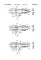
- FIG. 4Aillustrates a sealing device used in embodiments of the present invention in an initial purge position
- FIG. 4Billustrates the sealing device and material control device cooperating in a first position to draw material into the dispensing device
- FIG. 4Cillustrates the material control device and the sealing device cooperating in a second position to force material through a dispensing opening in the dispensing device.
- the present inventionwill now be described with reference to a dispensing system which is used to dispense viscous materials onto a substrate.
- a dispensing systemwhich is used to dispense viscous materials onto a substrate.
- embodiments of the present inventionare not limited to dispensing systems that dispense viscous materials onto substrates, but rather, the dispensing apparatus and methods in accordance with the embodiments of the present invention may be used in other applications requiring dispensing of a controlled amount of material from a container.
- the liquid dispensing system 10comprises a power control system 12 connected with a material control device 14 which is connected to a dispenser device 16.
- the material control device 14cooperates and interacts with the dispenser device 16 to deliver a controlled volume of material through a dispensing tip 22 and onto a substrate (not shown).
- a sealing device 20which is connected to a switching device 18.
- the switching devicecan move the sealing device 20 from a first position which allows material to enter into the dispensing chamber, but not exit the dispensing tip 22; and into a second position in which material is prevented from entering into the dispensing chamber, but may exit through the dispensing tip 22.
- the materialis drawn into the dispensing chamber when the sealing device is in the first position by a vacuum created in the dispensing chamber by the material control device.
- the power control system 12is a standard control system as is known in the art and is coupled to the material control device 14 to selectively determine the volume of material to be drawn into the chamber by displacing the material control device a selected distance.
- the switching device 18moves the sealing device 20 to a second position.
- the material control device 14is then returned to its original position forcing the material from the dispensing chamber through the dispensing tip 22 and onto the substrate.
- the material control device 14comprises a screw 30 and a piston 32.
- the piston 32may comprise a first portion 34 and a second portion 36.
- the first portion 34defines an opening 38 containing engagement teeth 40 to receive and mate with the screw 30.
- the second piston portion 36extends into the material control device chamber 58 (See FIG. 3).
- a piston with a diameter of 0.250 inchesis used. However, smaller or larger diameters may be used depending upon the volume of material to be dispensed.
- Self lubricating and abrasive resistant materialsare preferred.
- the rotation of the screw 30can be controlled so that when the screw mates with the piston 32, the second piston portion 36 is drawn away from the dispensing chamber and back through the material control device chamber 58 to create a vacuum within the chambers.
- the displacement distance of the second piston portion 36can be controlled by the number of turns made to the screw 30. By controlling the distance of displacement of the piston portion 36, it controls the amount of vacuum created in the chamber 58 and dispensing chamber 52. This in turn determines the amount of material which is drawn into the dispensing device 16 as will be shown herein.
- the dispensing device 16comprises a housing 50 which defines a chamber 52 for receiving material from an opening 54 which is to be dispensed through a second opening 60 and into a dispensing tip 22. Extending the length of the chamber 52 is the sealing device 20.
- the sealing device 20includes a first sealing portion 62 and a second sealing portion 64 connected by interconnect arm 66. The entire sealing device 20 is in connection with the switching device 18.
- the switching device 18may be implemented using a common switch or preferably a pneumatic cylinder which can be controlled through standard control systems that are known in the art.
- the switching device 18could also be driven from a cam, a wedge or rack and pinion, or a motor and screw, similar to the device shown in FIG. 2.
- the sealing device 20can be made from a range of material.
- the sealing devicemay be made from tungsten carbide, ceramic, or other hard materials (or a combination of the above).
- a stainless steel or other suitable materialmay be used.
- the first sealing portion 62 of the sealing device 20be located in a position which separates the opening 54 for the material entrance into the chamber 52 from the material control device chamber 58 and the material control device 14. In this manner, the first sealing portion 62 can create a seal between the material entrance opening 54 and the material control device chamber 58.
- a retaining device 56may be placed in the chamber 52 to assist in creating the seal with the first sealing portion 62 and also to prevent the first sealing portion 62 from rising to the level of the material entrance opening 54.
- the retaining device 56may have tapered edges to assist in the sealing process.
- the retaining devicemay be any of those known in the art.
- the first sealing portion 62may also be a ball and check valve or one of other similar sealing devices known in the art.
- the sealing device 20has a second sealing portion 64 connected by an interconnect arm 66 to the first sealing portion 62.
- This second sealing portion 64seals the opening above the dispensing head or tip 22 to prevent material from dispensing from the chamber 52.
- the first sealing portion 62, second sealing portion 64 and interconnect arm 66act in cooperation with each other so that when the switching device 18 moves the sealing device 20 from a first position to a second position, one of the seals created by either the first sealing portion 62 or the second sealing portion 64 is in an open position and the other seal is in a closed position.
- the dispensing device 16, switching device 18 and material control device 14can all be assembled and connected through various fastening means known in the art such as clamps, screws, bolts, pins, etc. In this manner, the entire assembly allows for easy construction, repair and cleaning.
- an adjustment device 80can be placed at the base of the dispensing device 16.
- the adjustment deviceallows for changes in the opening length for larger volumes of fluid flow.
- the adjustment device 80can comprise various known devices in the art such as screw on fasteners, twist caps, etc.
- FIG. 4Aillustrates the initial purge position of the dispensing device 10 before any material is entered into the chamber 52.
- a simple spacer device(not shown) is placed between the switching device 18 and the dispensing device 16. In doing so, this leaves the sealing device 20 in a half open/half closed position.
- the first sealing portion 62 and the second sealing portion 64do not complete or form seals anywhere within the chamber 52.
- material to be dispensedcan be sent into the chamber 52 through opening 54 and pass through the entire length of the chamber 52 and exit through the dispensing tip 22 via opening 60. This process purges any air from the chamber prior to dispensing.
- the switching device 18brings the sealing device 20 to the first position where the second sealing portion 64 seals the opening 60 over the dispensing tip 22.
- the first sealing portion 62does not form a seal and therefore allows an open pathway for material flow from the material opening 54 and into the lower portion of the chamber 52.
- the material control device 14is compressed a predetermined distance by the power control 12. This creates a vacuum to draw material through the material opening 54 and material supply (not shown) into the chamber 52.
- the liquid materialcan flow past the sealing device first portion 62 and past the retainer 56 and into the lower area of the chamber 52.
- the switching device 18moves the sealing device 20 to the second position after the volume of liquid has passed the first sealing portion 62. In this manner, the second sealing portion 64 is removed from the dispensing opening 60 which can allow for the material to escape and be dispensed onto the substrate (not shown).
- the material control device 14is returned to its initial position through the power control 12, preferably in the form of a servomotor.
- This returning force from the piston 36 and material control device 14forces the liquid in the chamber 52 to be pushed through opening 60 and through dispensing tip 22 onto a substrate.
- the interaction of the material control device 14, the switching device 18 and the sealing device 20allows for a distinct metered amount of liquid or paste to be provided to the substrate or depositing surface in a controlled manner.
Landscapes
- Physics & Mathematics (AREA)
- Fluid Mechanics (AREA)
- General Physics & Mathematics (AREA)
- Coating Apparatus (AREA)
Abstract
Description
Claims (21)
Priority Applications (9)
| Application Number | Priority Date | Filing Date | Title |
|---|---|---|---|
| US08/885,005US5957343A (en) | 1997-06-30 | 1997-06-30 | Controllable liquid dispensing device |
| US09/104,457US6085943A (en) | 1997-06-30 | 1998-06-24 | Controllable liquid dispensing device |
| CA002295722ACA2295722A1 (en) | 1997-06-30 | 1998-06-26 | Controllable liquid dispensing device |
| EP98931621AEP0993592A1 (en) | 1997-06-30 | 1998-06-26 | Controllable liquid dispensing device |
| KR1019997012514AKR20010014357A (en) | 1997-06-30 | 1998-06-26 | Controllable liquid dispensing device |
| JP50575599AJP4255517B2 (en) | 1997-06-30 | 1998-06-26 | Controllable liquid dispensing device |
| PCT/US1998/013283WO1999000646A1 (en) | 1997-06-30 | 1998-06-26 | Controllable liquid dispensing device |
| TW087110590ATW426800B (en) | 1997-06-30 | 1998-06-30 | Controllable liquid dispensing device |
| US09/611,502US6378737B1 (en) | 1997-06-30 | 2000-07-07 | Controllable liquid dispensing device |
Applications Claiming Priority (1)
| Application Number | Priority Date | Filing Date | Title |
|---|---|---|---|
| US08/885,005US5957343A (en) | 1997-06-30 | 1997-06-30 | Controllable liquid dispensing device |
Related Child Applications (1)
| Application Number | Title | Priority Date | Filing Date |
|---|---|---|---|
| US09/104,457Continuation-In-PartUS6085943A (en) | 1997-06-30 | 1998-06-24 | Controllable liquid dispensing device |
Publications (1)
| Publication Number | Publication Date |
|---|---|
| US5957343Atrue US5957343A (en) | 1999-09-28 |
Family
ID=25385920
Family Applications (1)
| Application Number | Title | Priority Date | Filing Date |
|---|---|---|---|
| US08/885,005Expired - LifetimeUS5957343A (en) | 1997-06-30 | 1997-06-30 | Controllable liquid dispensing device |
Country Status (4)
| Country | Link |
|---|---|
| US (1) | US5957343A (en) |
| CA (1) | CA2295722A1 (en) |
| TW (1) | TW426800B (en) |
| WO (1) | WO1999000646A1 (en) |
Cited By (36)
| Publication number | Priority date | Publication date | Assignee | Title |
|---|---|---|---|---|
| WO1999025169A1 (en) | 1997-11-10 | 1999-05-20 | Speedline Technologies, Inc. | Multiple head dispensing system and method |
| US6206964B1 (en)* | 1997-11-10 | 2001-03-27 | Speedline Technologies, Inc. | Multiple head dispensing system and method |
| US6214117B1 (en)* | 1998-03-02 | 2001-04-10 | Speedline Technologies, Inc. | Dispensing system and method |
| US6220487B1 (en) | 1998-10-16 | 2001-04-24 | Micro Robotics Systems, Inc. | Dispensing apparatus |
| WO2001055680A1 (en)* | 2000-01-26 | 2001-08-02 | Boehle Hartmut | Dosing device |
| US6378737B1 (en)* | 1997-06-30 | 2002-04-30 | Speedline Technologies, Inc. | Controllable liquid dispensing device |
| US6478200B1 (en)* | 1999-11-16 | 2002-11-12 | Imi Cornelius Inc. | Beverage dispense device |
| US20030155384A1 (en)* | 2002-02-20 | 2003-08-21 | Toyo Jidoki Co., Ltd. | Liquid filling nozzle and liquid filling apparatus |
| KR100454402B1 (en)* | 1999-07-29 | 2004-10-26 | 토레이 엔지니어링 컴퍼니, 리미티드 | Valve for intermittent feeding and apparatus for intermittent application |
| US20050056659A1 (en)* | 2003-09-15 | 2005-03-17 | Navarro Ramon M. | Sanitary fill valve assembly with adjustable flow regulator |
| US20050100457A1 (en)* | 2000-01-26 | 2005-05-12 | Dl Technology, Llc | System and method for control of fluid dispense pump |
| US6957783B1 (en) | 1999-01-26 | 2005-10-25 | Dl Technology Llc | Dispense tip with vented outlets |
| US6983867B1 (en) | 2002-04-29 | 2006-01-10 | Dl Technology Llc | Fluid dispense pump with drip prevention mechanism and method for controlling same |
| US20060097015A1 (en)* | 2004-10-28 | 2006-05-11 | Nordson Corporation | Method and system for dispensing liquid from a module having a flexible bellows seal |
| US20060108383A1 (en)* | 2004-11-22 | 2006-05-25 | Byerly David J | Device for dispensing a heated liquid having a flexible hydraulic seal |
| US7331482B1 (en) | 2003-03-28 | 2008-02-19 | Dl Technology, Llc | Dispense pump with heated pump housing and heated material reservoir |
| USRE40539E1 (en) | 1999-11-08 | 2008-10-14 | Dl Technology Llc | Fluid pump and cartridge |
| WO2009020256A1 (en)* | 2007-08-03 | 2009-02-12 | Sung-Gie Park | Fluid dispenser for dispensing fixed amount of fluid |
| US7744022B1 (en) | 1999-01-26 | 2010-06-29 | Dl Technology, Llc | Fluid dispense tips |
| US20100276522A1 (en)* | 2009-05-01 | 2010-11-04 | Dl Technology | Material dispense tips and methods for forming the same |
| US20110079618A1 (en)* | 2009-10-06 | 2011-04-07 | Nordson Corporation | Liquid dispensing module |
| US20130112719A1 (en)* | 2010-07-08 | 2013-05-09 | Sidel Participations | Filling device having a flow regulation system |
| US8690084B1 (en) | 2000-01-26 | 2014-04-08 | Dl Technology Llc | Fluid dispense tips |
| US8707559B1 (en) | 2007-02-20 | 2014-04-29 | Dl Technology, Llc | Material dispense tips and methods for manufacturing the same |
| US9057642B2 (en) | 2012-12-03 | 2015-06-16 | Illinois Tool Works Inc. | Method and apparatus for calibrating a dispenser |
| US9144818B2 (en) | 2013-03-13 | 2015-09-29 | Illinois Tool Works Inc. | Method and apparatus for dispensing a viscous material on a substrate |
| US9357686B2 (en) | 2013-11-14 | 2016-05-31 | Illinois Tool Works Inc. | Dispensing apparatus having substrate inverter system and clamping system, and method for dispensing a viscous material on a substrate |
| US9374905B2 (en) | 2013-09-30 | 2016-06-21 | Illinois Tool Works Inc. | Method and apparatus for automatically adjusting dispensing units of a dispenser |
| US9377114B2 (en) | 2012-04-25 | 2016-06-28 | Nordson Corporation | Pressure control valve for reactive adhesives |
| US9411779B2 (en) | 2012-09-28 | 2016-08-09 | Illinois Tool Works Inc. | Method of dispensing material based on edge detection |
| CN106015229A (en)* | 2016-06-06 | 2016-10-12 | 正信光电科技股份有限公司 | Gluing machine for photovoltaic modules |
| US9475078B2 (en) | 2012-10-29 | 2016-10-25 | Illinois Tool Works Inc. | Automated multiple head cleaner for a dispensing system and related method |
| US9662675B2 (en) | 2014-07-31 | 2017-05-30 | Illinois Tool Works Inc. | External inverter system for variable substrate thickness and method for rotating a substrate |
| US11370596B1 (en) | 2012-02-24 | 2022-06-28 | DL Technology, LLC. | Micro-volume dispense pump systems and methods |
| US11746656B1 (en) | 2019-05-13 | 2023-09-05 | DL Technology, LLC. | Micro-volume dispense pump systems and methods |
| EP4599944A1 (en)* | 2024-02-09 | 2025-08-13 | Nexperia B.V. | A dispensing device arranged for dispensing solder paste as well as a corresponding solder dot dispensing device and a related method |
Citations (27)
| Publication number | Priority date | Publication date | Assignee | Title |
|---|---|---|---|---|
| GB114905A (en)* | ||||
| US1184779A (en)* | 1914-11-17 | 1916-05-30 | James Shaw | Aerating fuel-pump for explosive-motors. |
| US1252875A (en)* | 1916-03-29 | 1918-01-08 | Ashmusen Mfg Company | Pump. |
| US1699236A (en)* | 1922-05-29 | 1929-01-15 | Gerson Stewart Corp Company | Liquid-dispensing valve |
| US2274241A (en)* | 1940-07-15 | 1942-02-24 | Savarian F Lemanski | Injector for internal combustion engines |
| US2410516A (en)* | 1945-09-24 | 1946-11-05 | Int Harvester Co | Bale loading device |
| US3586129A (en)* | 1969-07-07 | 1971-06-22 | Thw Inc | Metering device |
| US3921865A (en)* | 1975-01-30 | 1975-11-25 | Dale Electronics | Metering valve |
| US4043711A (en)* | 1975-04-24 | 1977-08-23 | Mikuni Kogyo Kabushiki Kaisha | Lubricating oil pump |
| US4572103A (en)* | 1984-12-20 | 1986-02-25 | Engel Harold J | Solder paste dispenser for SMD circuit boards |
| US4645431A (en)* | 1984-03-30 | 1987-02-24 | Sigma Enterprises, Inc. | Hydraulic pumping apparatus and method of operation |
| US4646969A (en)* | 1982-11-19 | 1987-03-03 | Ceskoslovenska Akademie Ved | Double acting mechanical pump liquid atomizer |
| US4708269A (en)* | 1985-07-10 | 1987-11-24 | Stork Bepak B.V. | Plunger-operated dispensing device |
| US4848606A (en)* | 1986-07-31 | 1989-07-18 | Tokyo Juki Industrial Co., Ltd. | Apparatus for dispensing a predetermined volume of paste-like fluid |
| US4967933A (en)* | 1989-02-27 | 1990-11-06 | Asymptotic Technologies, Inc. | Method and apparatus for dispensing viscous materials |
| US4974755A (en)* | 1989-04-20 | 1990-12-04 | Reagent Chemical & Research, Inc. | Dispensing valve assembly and system |
| US5044900A (en)* | 1990-03-01 | 1991-09-03 | Knight Tool Company, Inc. | Positive displacement shuttle pump |
| US5052338A (en)* | 1990-01-31 | 1991-10-01 | Asymptotic Technologies, Inc. | Apparatus for dispensing viscous materials a constant height above a workpiece surface |
| US5110615A (en)* | 1990-01-31 | 1992-05-05 | Asymptotic Technologies, Inc. | Method for dispensing viscous materials a constant height above a workpiece surface |
| US5137187A (en)* | 1991-02-20 | 1992-08-11 | H.G. Kalish | Anti-spray fluid dispensing nozzle |
| US5320250A (en)* | 1991-12-02 | 1994-06-14 | Asymptotic Technologies, Inc. | Method for rapid dispensing of minute quantities of viscous material |
| CH684850A5 (en)* | 1993-04-30 | 1995-01-13 | Water Line Sa | Dispensing apparatus for liquids |
| US5465879A (en)* | 1994-01-27 | 1995-11-14 | Asymptotic Technologies, Inc. | Disposable nozzle assembly for high speed viscous material droplet dispenser |
| WO1997013586A1 (en)* | 1995-10-13 | 1997-04-17 | Nordson Corporation | Flip chip underfill system and method |
| WO1997018054A1 (en)* | 1995-11-16 | 1997-05-22 | Nordson Corporation | Method and apparatus for dispensing small amounts of liquid material |
| US5666325A (en)* | 1995-07-31 | 1997-09-09 | Nordson Corporation | Method and apparatus for monitoring and controlling the dispensing of materials onto a substrate |
| US5765729A (en)* | 1996-02-08 | 1998-06-16 | Liquid Control Corporation | Dispenser for flowable materials |
- 1997
- 1997-06-30USUS08/885,005patent/US5957343A/ennot_activeExpired - Lifetime
- 1998
- 1998-06-26CACA002295722Apatent/CA2295722A1/ennot_activeAbandoned
- 1998-06-26WOPCT/US1998/013283patent/WO1999000646A1/ennot_activeApplication Discontinuation
- 1998-06-30TWTW087110590Apatent/TW426800B/ennot_activeIP Right Cessation
Patent Citations (28)
| Publication number | Priority date | Publication date | Assignee | Title |
|---|---|---|---|---|
| GB114905A (en)* | ||||
| US1184779A (en)* | 1914-11-17 | 1916-05-30 | James Shaw | Aerating fuel-pump for explosive-motors. |
| US1252875A (en)* | 1916-03-29 | 1918-01-08 | Ashmusen Mfg Company | Pump. |
| US1699236A (en)* | 1922-05-29 | 1929-01-15 | Gerson Stewart Corp Company | Liquid-dispensing valve |
| US2274241A (en)* | 1940-07-15 | 1942-02-24 | Savarian F Lemanski | Injector for internal combustion engines |
| US2410516A (en)* | 1945-09-24 | 1946-11-05 | Int Harvester Co | Bale loading device |
| US3586129A (en)* | 1969-07-07 | 1971-06-22 | Thw Inc | Metering device |
| US3921865A (en)* | 1975-01-30 | 1975-11-25 | Dale Electronics | Metering valve |
| US4043711A (en)* | 1975-04-24 | 1977-08-23 | Mikuni Kogyo Kabushiki Kaisha | Lubricating oil pump |
| US4646969A (en)* | 1982-11-19 | 1987-03-03 | Ceskoslovenska Akademie Ved | Double acting mechanical pump liquid atomizer |
| US4645431A (en)* | 1984-03-30 | 1987-02-24 | Sigma Enterprises, Inc. | Hydraulic pumping apparatus and method of operation |
| US4572103A (en)* | 1984-12-20 | 1986-02-25 | Engel Harold J | Solder paste dispenser for SMD circuit boards |
| US4708269A (en)* | 1985-07-10 | 1987-11-24 | Stork Bepak B.V. | Plunger-operated dispensing device |
| US4848606A (en)* | 1986-07-31 | 1989-07-18 | Tokyo Juki Industrial Co., Ltd. | Apparatus for dispensing a predetermined volume of paste-like fluid |
| US4967933A (en)* | 1989-02-27 | 1990-11-06 | Asymptotic Technologies, Inc. | Method and apparatus for dispensing viscous materials |
| US4974755A (en)* | 1989-04-20 | 1990-12-04 | Reagent Chemical & Research, Inc. | Dispensing valve assembly and system |
| US5052338A (en)* | 1990-01-31 | 1991-10-01 | Asymptotic Technologies, Inc. | Apparatus for dispensing viscous materials a constant height above a workpiece surface |
| US5110615A (en)* | 1990-01-31 | 1992-05-05 | Asymptotic Technologies, Inc. | Method for dispensing viscous materials a constant height above a workpiece surface |
| US5044900A (en)* | 1990-03-01 | 1991-09-03 | Knight Tool Company, Inc. | Positive displacement shuttle pump |
| US5137187A (en)* | 1991-02-20 | 1992-08-11 | H.G. Kalish | Anti-spray fluid dispensing nozzle |
| US5320250A (en)* | 1991-12-02 | 1994-06-14 | Asymptotic Technologies, Inc. | Method for rapid dispensing of minute quantities of viscous material |
| US5505777A (en)* | 1992-11-19 | 1996-04-09 | Asymptotic Technologies, Inc. | Computer controlled viscous fluid dispensing system |
| CH684850A5 (en)* | 1993-04-30 | 1995-01-13 | Water Line Sa | Dispensing apparatus for liquids |
| US5465879A (en)* | 1994-01-27 | 1995-11-14 | Asymptotic Technologies, Inc. | Disposable nozzle assembly for high speed viscous material droplet dispenser |
| US5666325A (en)* | 1995-07-31 | 1997-09-09 | Nordson Corporation | Method and apparatus for monitoring and controlling the dispensing of materials onto a substrate |
| WO1997013586A1 (en)* | 1995-10-13 | 1997-04-17 | Nordson Corporation | Flip chip underfill system and method |
| WO1997018054A1 (en)* | 1995-11-16 | 1997-05-22 | Nordson Corporation | Method and apparatus for dispensing small amounts of liquid material |
| US5765729A (en)* | 1996-02-08 | 1998-06-16 | Liquid Control Corporation | Dispenser for flowable materials |
Non-Patent Citations (6)
| Title |
|---|
| Engel, Jack, Selecting The Proper Dispensing Tip, Surface Mount Technology , Oct. 1990.* |
| Engel, Jack, Selecting The Proper Dispensing Tip, Surface Mount Technology, Oct. 1990. |
| Hogan, Brian, J. Adhesive Dispenser Provides ±2% Volume Repeatability, Design News, Apr. 11, 1994. |
| Hogan, Brian, J. Adhesive Dispenser Provides 2% Volume Repeatability, Design News , Apr. 11, 1994.* |
| International Search ing Authority, PCT Notification of Transmittal of International Search Report or the Declaration .* |
| International Search ing Authority, PCT Notification of Transmittal of International Search Report or the Declaration. |
Cited By (87)
| Publication number | Priority date | Publication date | Assignee | Title |
|---|---|---|---|---|
| US6378737B1 (en)* | 1997-06-30 | 2002-04-30 | Speedline Technologies, Inc. | Controllable liquid dispensing device |
| US6206964B1 (en)* | 1997-11-10 | 2001-03-27 | Speedline Technologies, Inc. | Multiple head dispensing system and method |
| WO1999025169A1 (en) | 1997-11-10 | 1999-05-20 | Speedline Technologies, Inc. | Multiple head dispensing system and method |
| US6214117B1 (en)* | 1998-03-02 | 2001-04-10 | Speedline Technologies, Inc. | Dispensing system and method |
| US6220487B1 (en) | 1998-10-16 | 2001-04-24 | Micro Robotics Systems, Inc. | Dispensing apparatus |
| US7744022B1 (en) | 1999-01-26 | 2010-06-29 | Dl Technology, Llc | Fluid dispense tips |
| US8480015B1 (en) | 1999-01-26 | 2013-07-09 | Dl Technology, Llc | Fluid dispense tips |
| US8056833B1 (en) | 1999-01-26 | 2011-11-15 | Dl Technology, Llc | Dispense tip with vented outlets |
| US9180482B1 (en) | 1999-01-26 | 2015-11-10 | DL Technology, LLC. | Fluid dispense tips |
| US7762480B1 (en) | 1999-01-26 | 2010-07-27 | DL Technology, LLC. | Dispense tip with vented outlets |
| US7178745B1 (en) | 1999-01-26 | 2007-02-20 | Dl Technology, Llc | Dispense tip with vented outlets |
| US9833807B2 (en) | 1999-01-26 | 2017-12-05 | DL Technology, LLC. | Fluid dispense tips |
| US6957783B1 (en) | 1999-01-26 | 2005-10-25 | Dl Technology Llc | Dispense tip with vented outlets |
| KR100454402B1 (en)* | 1999-07-29 | 2004-10-26 | 토레이 엔지니어링 컴퍼니, 리미티드 | Valve for intermittent feeding and apparatus for intermittent application |
| USRE40539E1 (en) | 1999-11-08 | 2008-10-14 | Dl Technology Llc | Fluid pump and cartridge |
| US8197582B1 (en) | 1999-11-08 | 2012-06-12 | DL Technology, LLC. | Fluid dispensing system having vacuum unit |
| US7905945B1 (en) | 1999-11-08 | 2011-03-15 | DL Technology, LLC. | Fluid dispensing system having vacuum unit and method of drawing a vacuum in a fluid dispensing system |
| US9228582B1 (en) | 1999-11-08 | 2016-01-05 | DL Technology, LLC. | Fluid pump and cartridge |
| US7448857B1 (en) | 1999-11-08 | 2008-11-11 | Dl Technology, Llc | Fluid pump and cartridge |
| US6478200B1 (en)* | 1999-11-16 | 2002-11-12 | Imi Cornelius Inc. | Beverage dispense device |
| WO2001055680A1 (en)* | 2000-01-26 | 2001-08-02 | Boehle Hartmut | Dosing device |
| US9573156B1 (en) | 2000-01-26 | 2017-02-21 | Dl Technology, Llc | Fluid dispense tips |
| US6892959B1 (en) | 2000-01-26 | 2005-05-17 | Dl Technology Llc | System and method for control of fluid dispense pump |
| US9242770B2 (en) | 2000-01-26 | 2016-01-26 | Dl Technology, Llc | Fluid dispense tips |
| US20050100457A1 (en)* | 2000-01-26 | 2005-05-12 | Dl Technology, Llc | System and method for control of fluid dispense pump |
| US7000853B2 (en) | 2000-01-26 | 2006-02-21 | Dl Technology, Llc | System and method for control of fluid dispense pump |
| US8690084B1 (en) | 2000-01-26 | 2014-04-08 | Dl Technology Llc | Fluid dispense tips |
| US6729507B2 (en)* | 2002-02-20 | 2004-05-04 | Toyo Jidoki Co., Ltd. | Liquid filling nozzle and liquid filling apparatus |
| US20030155384A1 (en)* | 2002-02-20 | 2003-08-21 | Toyo Jidoki Co., Ltd. | Liquid filling nozzle and liquid filling apparatus |
| US11364517B1 (en) | 2002-04-29 | 2022-06-21 | DL Technology, LLC. | Fluid dispense pump with drip prevention mechanism and method for controlling same |
| US7694857B1 (en) | 2002-04-29 | 2010-04-13 | Dl Technology, Llc | Fluid dispense pump with drip prevention mechanism and method for controlling same |
| US9108215B1 (en) | 2002-04-29 | 2015-08-18 | Dl Technology, Llc | Fluid dispense pump with drip prevention mechanism and method for controlling same |
| US9833808B1 (en) | 2002-04-29 | 2017-12-05 | Dl Technology, Llc | Fluid dispense pump with drip prevention mechanism and method for controlling same |
| US10814344B1 (en) | 2002-04-29 | 2020-10-27 | DL Technology, LLC. | Fluid dispense pump with drip prevention mechanism and method for controlling same |
| US8220669B1 (en) | 2002-04-29 | 2012-07-17 | Dl Technology, Llc | Fluid dispense pump with drip prevention mechanism and method for controlling same |
| US8701946B1 (en) | 2002-04-29 | 2014-04-22 | Dl Technology, Llc | Fluid dispense pump with drip prevention mechanism and method for controlling same |
| US6983867B1 (en) | 2002-04-29 | 2006-01-10 | Dl Technology Llc | Fluid dispense pump with drip prevention mechanism and method for controlling same |
| US7331482B1 (en) | 2003-03-28 | 2008-02-19 | Dl Technology, Llc | Dispense pump with heated pump housing and heated material reservoir |
| US20050056659A1 (en)* | 2003-09-15 | 2005-03-17 | Navarro Ramon M. | Sanitary fill valve assembly with adjustable flow regulator |
| US7156262B2 (en) | 2003-09-15 | 2007-01-02 | Navarro Ramon M | Sanitary fill valve assembly with adjustable flow regulator |
| US7617955B2 (en) | 2004-10-28 | 2009-11-17 | Nordson Corporation | Method and system for dispensing liquid from a module having a flexible bellows seal |
| US20060097015A1 (en)* | 2004-10-28 | 2006-05-11 | Nordson Corporation | Method and system for dispensing liquid from a module having a flexible bellows seal |
| US7296714B2 (en)* | 2004-11-22 | 2007-11-20 | Nordson Corporation | Device for dispensing a heated liquid having a flexible hydraulic seal |
| US20060108383A1 (en)* | 2004-11-22 | 2006-05-25 | Byerly David J | Device for dispensing a heated liquid having a flexible hydraulic seal |
| US10583454B1 (en) | 2007-02-20 | 2020-03-10 | Dl Technology, Llc | Material dispense tip |
| US8707559B1 (en) | 2007-02-20 | 2014-04-29 | Dl Technology, Llc | Material dispense tips and methods for manufacturing the same |
| US9486830B1 (en) | 2007-02-20 | 2016-11-08 | DL Technology, LLC. | Method for manufacturing a material dispense tip |
| US12303929B1 (en) | 2007-02-20 | 2025-05-20 | DL Technology, LLC. | Material dispense tips |
| US11292025B1 (en) | 2007-02-20 | 2022-04-05 | DL Technology, LLC. | Material dispense tips and methods for manufacturing the same |
| US11648581B1 (en) | 2007-02-20 | 2023-05-16 | DL Technology, LLC. | Method for manufacturing a material dispense tip |
| US12017247B1 (en) | 2007-02-20 | 2024-06-25 | DL Technology, LLC. | Material dispense tips |
| WO2009020256A1 (en)* | 2007-08-03 | 2009-02-12 | Sung-Gie Park | Fluid dispenser for dispensing fixed amount of fluid |
| US9272303B1 (en) | 2009-05-01 | 2016-03-01 | Dl Technology, Llc | Material dispense tips and methods for forming the same |
| US11420225B1 (en) | 2009-05-01 | 2022-08-23 | DL Technology, LLC. | Material dispense tips and methods for forming the same |
| US20100276522A1 (en)* | 2009-05-01 | 2010-11-04 | Dl Technology | Material dispense tips and methods for forming the same |
| US8864055B2 (en) | 2009-05-01 | 2014-10-21 | Dl Technology, Llc | Material dispense tips and methods for forming the same |
| US12145170B1 (en) | 2009-05-01 | 2024-11-19 | DL Technology, LLC. | Material dispense tips and methods for forming the same |
| US10722914B1 (en) | 2009-05-01 | 2020-07-28 | DL Technology, LLC. | Material dispense tips and methods for forming the same |
| US10105729B1 (en) | 2009-05-01 | 2018-10-23 | DL Technology, LLC. | Material dispense tips and methods for forming the same |
| US11738364B1 (en) | 2009-05-01 | 2023-08-29 | DL Technology, LLC. | Material dispense tips and methods for forming the same |
| US20110079618A1 (en)* | 2009-10-06 | 2011-04-07 | Nordson Corporation | Liquid dispensing module |
| US8333307B2 (en) | 2009-10-06 | 2012-12-18 | Nordson Corporation | Liquid dispensing module |
| US20130112719A1 (en)* | 2010-07-08 | 2013-05-09 | Sidel Participations | Filling device having a flow regulation system |
| US9114969B2 (en)* | 2010-07-08 | 2015-08-25 | Sidel Participations | Filling device having a flow regulation system |
| US11370596B1 (en) | 2012-02-24 | 2022-06-28 | DL Technology, LLC. | Micro-volume dispense pump systems and methods |
| US9377114B2 (en) | 2012-04-25 | 2016-06-28 | Nordson Corporation | Pressure control valve for reactive adhesives |
| US9779494B2 (en) | 2012-09-28 | 2017-10-03 | Illinois Tool Works Inc. | Apparatus for dispensing material based on edge detection |
| US9411779B2 (en) | 2012-09-28 | 2016-08-09 | Illinois Tool Works Inc. | Method of dispensing material based on edge detection |
| US9475078B2 (en) | 2012-10-29 | 2016-10-25 | Illinois Tool Works Inc. | Automated multiple head cleaner for a dispensing system and related method |
| US10010900B2 (en) | 2012-10-29 | 2018-07-03 | Illinois Tool Works Inc. | Automated multiple head cleaner for a dispensing system and related method |
| US9057642B2 (en) | 2012-12-03 | 2015-06-16 | Illinois Tool Works Inc. | Method and apparatus for calibrating a dispenser |
| US9144818B2 (en) | 2013-03-13 | 2015-09-29 | Illinois Tool Works Inc. | Method and apparatus for dispensing a viscous material on a substrate |
| US9636699B2 (en) | 2013-03-13 | 2017-05-02 | Illinois Tool Works Inc. | Method and apparatus for dispensing a viscous material on a substrate |
| US10966323B2 (en) | 2013-09-30 | 2021-03-30 | Illinois Tool Works Inc. | Method and apparatus for automatically adjusting dispensing units of a dispenser |
| US9936585B2 (en) | 2013-09-30 | 2018-04-03 | Illinois Tool Works Inc. | Method and apparatus for automatically adjusting dispensing units of a dispenser |
| US11395410B2 (en) | 2013-09-30 | 2022-07-19 | Illinois Tool Works Inc. | Method and apparatus for automatically adjusting dispensing units of a dispenser |
| US9775250B2 (en) | 2013-09-30 | 2017-09-26 | Illinois Tool Works Inc. | Method and apparatus for automatically adjusting dispensing units of a dispenser |
| US10244634B2 (en) | 2013-09-30 | 2019-03-26 | Illinois Tool Works Inc. | Method and apparatus for automatically adjusting dispensing units of a dispenser |
| US9374905B2 (en) | 2013-09-30 | 2016-06-21 | Illinois Tool Works Inc. | Method and apparatus for automatically adjusting dispensing units of a dispenser |
| US9357686B2 (en) | 2013-11-14 | 2016-05-31 | Illinois Tool Works Inc. | Dispensing apparatus having substrate inverter system and clamping system, and method for dispensing a viscous material on a substrate |
| US9662675B2 (en) | 2014-07-31 | 2017-05-30 | Illinois Tool Works Inc. | External inverter system for variable substrate thickness and method for rotating a substrate |
| CN106015229A (en)* | 2016-06-06 | 2016-10-12 | 正信光电科技股份有限公司 | Gluing machine for photovoltaic modules |
| CN106015229B (en)* | 2016-06-06 | 2018-06-26 | 正信光电科技股份有限公司 | Photovoltaic module adhesive supplier |
| US11746656B1 (en) | 2019-05-13 | 2023-09-05 | DL Technology, LLC. | Micro-volume dispense pump systems and methods |
| US12338821B1 (en) | 2019-05-13 | 2025-06-24 | DL Technology, LLC. | Micro-volume dispense pump systems and methods |
| EP4599944A1 (en)* | 2024-02-09 | 2025-08-13 | Nexperia B.V. | A dispensing device arranged for dispensing solder paste as well as a corresponding solder dot dispensing device and a related method |
| WO2025168788A1 (en)* | 2024-02-09 | 2025-08-14 | Nexperia B.V. | A dispensing device arranged for dispensing solder paste as well as a corresponding solder dot dispensing device and a related method |
Also Published As
| Publication number | Publication date |
|---|---|
| TW426800B (en) | 2001-03-21 |
| WO1999000646A1 (en) | 1999-01-07 |
| CA2295722A1 (en) | 1999-01-07 |
Similar Documents
| Publication | Publication Date | Title |
|---|---|---|
| US5957343A (en) | Controllable liquid dispensing device | |
| US6085943A (en) | Controllable liquid dispensing device | |
| US5971227A (en) | Liquid dispensing system with improved sealing augering screw and method for dispensing | |
| US8545931B2 (en) | Thin line conformal coating method | |
| US5927560A (en) | Dispensing pump for epoxy encapsulation of integrated circuits | |
| KR101769835B1 (en) | Discharge device and liquid dispensing device, and method for dispensing liquid | |
| KR100592504B1 (en) | Liquid Dispensing Method and Apparatus | |
| EP1029626B1 (en) | Method and apparatus for dispensing small amounts of liquid material | |
| US5195656A (en) | Accurately controlled fluid dispenser with upper and lower stroke adjusters | |
| CN1070377A (en) | Piston distribution device | |
| US20060193969A1 (en) | Method and apparatus for streaming a viscous material on a substrate | |
| US4942984A (en) | Dripless solder paste dispenser | |
| JP3342841B2 (en) | Liquid metering method and apparatus | |
| JPH10277457A (en) | Adhesive coating device | |
| US5779147A (en) | Dosing nozzle assembly and process for dosing liquid | |
| JP2000317352A (en) | Nozzle for liquid quantitative discharge device | |
| US7543720B2 (en) | Method and apparatus for dispensing small volumes of fluid | |
| JPH0733907Y2 (en) | Dispenser for small amount of liquid discharge | |
| KR20000056426A (en) | A fluid fixed quantity method and the dispenser | |
| JP2001278389A (en) | Device and method for filling liquid resin into syringe | |
| HK1236882A1 (en) | Liquid material discharge apparatus and method | |
| JPH03137959A (en) | Device for supplying a predetermined amount of fluid substance | |
| JPS63319078A (en) | Discharger | |
| HK1195283A (en) | Liquid material discharge apparatus and method |
Legal Events
| Date | Code | Title | Description |
|---|---|---|---|
| AS | Assignment | Owner name:CAMELOT SYSTEMS, INC., MASSACHUSETTS Free format text:ASSIGNMENT OF ASSIGNORS INTEREST;ASSIGNOR:CAVALLARO, WILLIAM;REEL/FRAME:008921/0410 Effective date:19980116 | |
| AS | Assignment | Owner name:SPEEDLINE TECHNOLOGIES, INC., MASSACHUSETTS Free format text:ASSIGNMENT OF ASSIGNORS INTEREST;ASSIGNOR:CAMELOT SYSTEMS, INC.;REEL/FRAME:009711/0824 Effective date:19981231 | |
| STCF | Information on status: patent grant | Free format text:PATENTED CASE | |
| FEPP | Fee payment procedure | Free format text:PAYOR NUMBER ASSIGNED (ORIGINAL EVENT CODE: ASPN); ENTITY STATUS OF PATENT OWNER: LARGE ENTITY | |
| FPAY | Fee payment | Year of fee payment:4 | |
| AS | Assignment | Owner name:SPEEDLINE HOLDINGS I, LLC, NEW YORK Free format text:NOTICE OF GRANT OF SECURITY INTEREST IN PATENTS;ASSIGNOR:SPEEDLINE TECHNOLOGIES, INC.;REEL/FRAME:014943/0593 Effective date:20040105 | |
| AS | Assignment | Owner name:KPS SPECIAL SITUATIONS FUND II L.P., NEW YORK Free format text:ASSIGNMENT OF ASSIGNORS INTEREST;ASSIGNOR:SPEEDLINE TECHNOLOGIES, INC.;REEL/FRAME:015460/0737 Effective date:20040521 | |
| AS | Assignment | Owner name:SPEEDLINE TECHNOLOGIES, INC., MASSACHUSETTS Free format text:RELEASE BY SECURED PARTY;ASSIGNOR:SPEEDLINE HOLDINGS I, LLC;REEL/FRAME:018480/0775 Effective date:20061106 | |
| FPAY | Fee payment | Year of fee payment:8 | |
| FPAY | Fee payment | Year of fee payment:12 |