US5956638A - Method for unlicensed band port to autonomously determine interference threshold and power level - Google Patents
Method for unlicensed band port to autonomously determine interference threshold and power levelDownload PDFInfo
- Publication number
- US5956638A US5956638AUS08/590,751US59075196AUS5956638AUS 5956638 AUS5956638 AUS 5956638AUS 59075196 AUS59075196 AUS 59075196AUS 5956638 AUS5956638 AUS 5956638A
- Authority
- US
- United States
- Prior art keywords
- transmission power
- channel
- level
- interference threshold
- sub
- Prior art date
- Legal status (The legal status is an assumption and is not a legal conclusion. Google has not performed a legal analysis and makes no representation as to the accuracy of the status listed.)
- Expired - Fee Related
Links
Images


Classifications
- H—ELECTRICITY
- H04—ELECTRIC COMMUNICATION TECHNIQUE
- H04W—WIRELESS COMMUNICATION NETWORKS
- H04W52/00—Power management, e.g. Transmission Power Control [TPC] or power classes
- H04W52/04—Transmission power control [TPC]
- H04W52/18—TPC being performed according to specific parameters
- H04W52/24—TPC being performed according to specific parameters using SIR [Signal to Interference Ratio] or other wireless path parameters
- H—ELECTRICITY
- H04—ELECTRIC COMMUNICATION TECHNIQUE
- H04B—TRANSMISSION
- H04B7/00—Radio transmission systems, i.e. using radiation field
Definitions
- the present inventionis directed to a wireless communication system and, more particularly, to a method for radio ports in the unlicensed personal communications spectrum to autonomously determine an interference threshold and transmission power level.
- the Federal Communications Commissionhas designated the frequency band between 1920 and 1930 MHz as an unlicensed band for isochronous personal communications services (UPCS). This unlicensed band will be used primarily to support wireless telephone and circuit-switched data.
- UPCSisochronous personal communications services
- the maximum permitted transmission power of 55 mW for 300 kHz bandwidthlimits UPCS to indoor use, because the power level is too low for effective use outdoors.
- FIG. 1is an example of a simple UPCS system 50.
- a customerhas a mobile terminal (MT) 52, such as a wireless telephone or key set, which is in wireless communication with a radio port (RP) 54 connected to a radio port control unit (RPCU) 56.
- RPradio port
- a UPCS systemmay have a number of RPs 54 connected to the same or a different RPCU 56.
- the RPCU 56may be connected to a communications network, such as an ordinary telephone line 58 which connects to a local switch 60.
- the switchconnects to a telephone network, such as a public switched telephone network (PSTN) 62.
- PSTNpublic switched telephone network
- the customermay have personal information, such as a telephone or personal communications number, call forwarding and routing information, account information, credit and billing information, and the like stored in a telephone network database, known as the Home Location Register (HLR) 64, servicing the customer's home area.
- HLRHome Location Register
- the 1920-1930 MHz bandwas previously allocated to licensed point-to-point microwave communication.
- the FCChas instituted strict requirements on the use of UPCS systems, at least until all of the point-to-point microwave systems are cleared from the band. It is expected that this clearing process may take as long as seven years. To this end, the FCC requires that UPCS components cannot transmit if they move outside of certain authorized areas. For this reason, it is generally believed that only large, geographically bound systems, such as Centrex and PBX systems may be used until the band is cleared. It also implicitly requires that the RP 54, not the MT 52 (which is capable of moving outside of authorized areas), must initiate communications.
- the UPCS bandis unlicensed, it is available for use without paying the FCC a license fee for each piece of radio equipment installed.
- the FCCrequires an etiquette for obtaining channels in the UPCS band. This etiquette is called the Listen-Before-Talk (LBT) etiquette.
- LBTListen-Before-Talk
- each RPmust find an available channel in the band on which to transmit.
- the FCChas divided the band into eight 1.25 MHz channels.
- “Narrow band”e.g., less than 625 kHz occupied signal bandwidth
- “Wide band” communications devicesare required to begin searching for available channels at the higher 3 MHz of the band. The following description will refer to narrow band communications devices, but the reader understands that it is equally applicable to wide band communications devices. Protocols in the UPCS spectrum may divide each 1.25 MHz channel into a number of system channels.
- the RP 54begins its search by measuring a first channel (e.g., randomly selected from the system channels contained in the bottom 3 MHz of the band) in the band to determine if interference below a threshold (the FCC requires the threshold to be no larger than 30 dB above a background level, except in special cases) is present. Interference above the threshold level indicates that the channel may already be taken by a nearby RP and is not available.
- the RPmonitors the channel for the threshold level of interference for 10 ms before it can transmit, to make sure that another RP has not already acquired the channel. If the channel has interference beyond the threshold at any time during the 10 ms period, it searches the next higher channel. An RP must acquire the first channel it monitors and detects no interference above the threshold for 10 ms.
- the RP 54Once the RP 54 has acquired a channel, it is required to transmit immediately on that channel to "advertise" its availability for communications with an MT 52. If the RP 54 does not establish communication with an MT within that 30 second time period, the RP must relinquish the channel, and begin again its search for an available channel.
- PACS-UBis a protocol which is adapted for use in the UPCS spectrum.
- the following descriptionuses the PACS-UB protocol to illustrate the present invention. The reader understands, however, the principles of the invention apply to any protocol operable in the UPCS spectrum or that uses an LBT etiquette.
- the PACS-UB protocolmeets the FCC UPCS requirements by using a "blinking beacon" protocol. This means that the RPs 54 transmit “beacon" signals that MTs 52 use to find RPs with which they can establish a communications channel.
- This "blinking beacon”is preferably accomplished using the PACS-UB hyperframe and superframe structures, illustrated in FIG. 2.
- FIG. 2illustrates a preferred PACS-UB hyperframe 200 which comprises 30 one second superframes 202.
- These superframes 202are system broadcast channel superframes (SBC-SF).
- SBC-SFsystem broadcast channel superframes
- An RPbroadcasts an access superframe when it is attempting to acquire a channel.
- FIG. 2shows an access superframe 202' in detail.
- the access superframe 202'is preferably divided into four phases 204, 206, 208, 210. These phases are:
- a first 200 ms period 204(phase A) during which an active RP 54 transmits incoming call alerts or short messages to the MT 52;
- phase Ba second 200 ms period 206 (phase B) during which an active RP 54 transmits system and other service information
- phase Ca 400 ms period 208 (phase C) for idle ports to select a channel on which to transmit based on signal strength
- phase Da third 200 ms period 210 (phase D) during which the MTs 52 select an RP 54 having the best signal strength to which the MT has access rights (i.e., the MT is from the same system).
- FIG. 3is a histogram 300 showing an RP's signal level measurements of the channels in an illustrative PACS-UB protocol system in the UPCS spectrum at a period in time.
- PACS-UBfurther divides each of the eight 1.25 MHZ channels into four 300 kHz system channels, providing 32 total channels.
- a threshold level This used to determine whether or not a channel is available to an RP. If this threshold is set to a high level, such as Th 1 in FIG. 3, very noisy channels will be accepted resulting in suboptimal performance. In FIG. 3, a relatively noisy channel such as channel 2 is below the threshold.
- a noisy channelsuch as channel 2 may be acquired even though much quieter channels, such as channels 9 and 11, are available.
- the FCCfixes a maximum level of 30 dB above a background noise level, which background level is about -118 dBm in a PACS-UB protocol system. However, this maximum level may be increased by up to 20 dB by reducing the RP's transmission power by a corresponding amount.
- the threshold levelis set very low, such as Th 3 in FIG. 3, only very quiet channels will be selected. Few, if any, channels meeting this low threshold may be available, thus preventing RPs from finding an available channel. In FIG. 3, only channel 31 is below the Th 3 level. If several RPs are searching for channels and these RPs "hear" approximately the same signal levels as this RP, this channel may be acquired, leaving no channels available for this and other RPs.
- an intermediate threshold levelsuch as Th 2
- Th 2an intermediate threshold level
- the signal levels for the channelschange over time with call arrivals and departures.
- Th 2may be the preferred threshold level.
- a different threshold levelmay be better for the signal levels measured at that time.
- FIG. 4is a chart 400 showing the number of times each of the 32 channels is selected in an illustrative PACS-UB system.
- the LBT protocolrequires an RP to select the first channel it encounters having less than the threshold level of interference for the 10 ms period.
- the LBT protocolalso requires an RP to begin its channel search in the lower 3 MHz of the band and search upward until an available channel is found. (For wide band systems, the search begins in the higher 3 MHz of the band.)
- These two requirementsresult in the lowest frequency channels being acquired more often than the higher frequency channels (the converse is true for wide bandwidth systems). This is illustrated in FIG. 4.
- the curve labeled "actual"indicates how often channels are acquired in a relatively simple UPCS system.
- the threshold levelshould be adjusted to an appropriate level which is neither too high nor too low for the relevant conditions of the system.
- the relevant conditionssuch as RP spacing, current UPCS spectrum usage, and local propagation conditions--vary from system to system and even from time to time within the same system.
- the optimal threshold valuemay differ between RPs in the same system, and may vary for each RP over time as the relevant conditions change. Thus, it is difficult or impossible to select a single threshold value that will provide a channel distribution approaching the ideal at all times even for a single system.
- the threshold levelin some instances, is related to the RP transmission power.
- the FCChas limited the maximum transmission power for devices operating in the UPCS spectrum.
- This maximum power levelis proportional to the square root of the transmission bandwidth. In the PACS-UB protocol, this maximum transmission power is about 17 dBm.
- the FCCallows the interference threshold to be increased from the 30 dB maximum, provided that the transmission power be decreased a corresponding amount below the maximum. For example, in a crowded, noisy environment, an RP may require an interference threshold of 35 dB.
- the FCCpermits the threshold to be increased to this level, provided that the transmission power is reduced by 5 dBm. Thus, in the PACS-UB example discussed here, the maximum transmission power is reduced to 12 dBm.
- FIG. 5is a diagram illustrating one floor of a building 500 having a UPCS system.
- the buildingcomprises three parts, an office suite 502, having a high density of RPs 54, a factory 504, having an intermediate density of RPs 54, and a warehouse 506, having a low density of RPs 54.
- the RPs' transmissionscreate coverage areas 508 which are indicated in FIG. 5 as a circle (or part of a circle).
- the RPs 54are arranged so that the entire area is covered by the coverage areas 508.
- an MT 52will be in wireless communication with an RP 54 regardless of the MTs location in the building 500.
- the coverage areas 508 in the office 502cover less area than those in the factory 504 or the warehouse 506 (some coverage area overlap is preferred to prevent gaps in the RP coverage).
- the transmission power of the office 502 RPs 54is lower than that of the RPs 54 in the factory 504 or the warehouse 506.
- the transmission power of the RPs 54 in an areaneed not be the same.
- RP 54'has a higher transmission power than RP 54".
- the interference thresholdmay change adaptively, and the transmission power should be able to change accordingly.
- each radio portadaptively, autonomously sets its interference threshold and/or transmission power levels. This may be done, for example, by the RP measuring the signal level on each channel and then setting the interference threshold and/or power level according to these measurements.
- t he interference thresholdis determined by measuring the signal level on each channel, ranking the channels in order of the measure d signal level, and using these rankings to determine the threshold.
- the transmission power levelmay be set with reference to the adaptive interference threshold. This level is determined by using the system and FCC power limitations and current propagation conditions to provide a satisfactory transmission level.
- the equation for determining the interference thresholdis:
- RSSI nis the ranked RF energy (e.g., signal level) detected by a received signal strength indicator (RSSI), wherein the rank is from lowest to highest (e.g., RSSI 2 is the second lowest RF energy); and
- RSSIreceived signal strength indicator
- kTBis a background noise level.
- the equation for determining the transmission power with respect to the interference thresholdis:
- TXis the transmission power
- TX maxis the maximum transmission power permitted by the FCC
- TX minis a system dependent minimum transmission power
- This the interference threshold.
- FIG. 1illustrates an unlicensed personal communications system
- FIG. 2illustrates a hyperframe/superframe structure of an illustrative PACS-UB system
- FIG. 3is a histogram showing signal levels for channels is an illustrative PACS-UB system in the UPCS;
- FIG. 4is a chart showing the number of times each channel is selected by an illustrative PACS-UB system in the spectrum
- FIG. 5is a diagram illustrating one floor of a building having a UPCS system
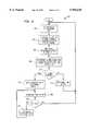
- FIG. 6is a flowchart of a preferred method of autonomously determining an interference threshold
- FIG. 7is a timing diagram illustrating a preferred method of autonomously determining interference threshold.
- the present inventionis a method for radio ports in a UPCS system to adaptively determine an interference threshold and/or transmission power level. This is preferably accomplished by measuring the signal strength on all of the channels and determining the threshold and/or level using these measurements.
- the optimal threshold valuemay differ between RPs in the same system, and may vary for each RP over time as the relevant conditions change.
- a method for adaptively, autonomously determining an interface threshold levelis provided. This allows each RP to choose a threshold value based on the channel signal levels at a particular moment in time.
- the LBT etiquetterequires an RP to measure the signal levels on the channels in the band.
- the RPmeasures the signal level it detects for all of the channels, ranks these channels in order of detected signal level, and uses these measurements to select an interference threshold level.
- the measurementsmay be taken by a received signal strength indicator (RSSI) in the RP used to measure the channel signal levels.
- RSSIreceived signal strength indicator
- This the interference threshold
- RSSI nis the ranked signal level detected by a received signal strength indicator, wherein the rank is from lowest to highest (e.g., RSSI 2 is the second quietest channel);
- kTBis a background noise level.
- Each RPchooses an optimal threshold for the interference conditions it experiences.
- the thresholdis chosen based on the second and third quietest channels (e.g., having the second and third lowest measured RF energies). For this equation, the threshold is always 2 dB higher than the level for the two best channels, to account for some inaccuracy or error in the measurement process. If the third best channel exceeds the level of the second best channel by less than 2 dB, the level is raised to that of the third best channel. Thus, if the two quietest channels are much quieter than the third quietest (e.g., more than 2 dB quieter), then the difference between the second and third quietest levels is added to the second quietest level. Otherwise a minimum amount of 2 dB is added to the second quietest level.
- FIG. 6is a flow chart 600 illustrating the inventive method for determining the interference threshold.
- an RPis operating within the PACS-UB protocol and is using the "stagger start" method described in the related application referred to above.
- the methodbegins by initializing the hyperframe timer (step 602). At a predetermined time, such as the last 40 ms of an RP's access superframe phase B 206, the RP measures the signal levels of each channel in the UPCS spectrum (step 604). If there are 32 channels, and all channels are measured in a total of 40 ms, then each channel is monitored for 1.25 ms. These 32 measurements give the RP an overview of the interference levels it detects in the band. Using these measurements, the channels are ranked in order of signal level and the threshold interference level is determined (step 606).
- the RPperforms the LBT etiquette during superframe phase C according to the RPs' assigned stagger start time and using the determined threshold (step 608).
- the RPmonitors a channel to determine if it is available to acquire. If it detects interference above the threshold interference level before 10 ms has expired, it abandons that channel and monitors the next channel. If it does not detect interference above the threshold level for the entire 10 ms period, it acquires that channel and immediately transmits on it.
- step 610If an RF channel is not acquired (step 610) (e.g., no channel has a signal level below the threshold), the hyperframe timer expires (e.g., 30 seconds) and the process begins again (step 612). If a channel is acquired (step 610) (e.g., the RP acquired the first channel having a signal level below the threshold), the RP begins transmitting (e.g., "advertising" its availability to MTs) on the acquired channel (step 614).
- a channele.g., the RP acquired the first channel having a signal level below the threshold
- the RPbegins transmitting (e.g., "advertising" its availability to MTs) on the acquired channel (step 614).
- step 616if the RP is not communicating with an MT (step 618), it relinquishes the channel and begins the process again. If the RP is communicating with an MT (step 618), the hyperframe timer is re-initialized (step 620) until the RP is no longer communicating with an MT.
- RP nis assigned a stagger start in phase C 208 of the next superframe SBC-SF i+1 . That is, SBC-SF i+1 is RP n 's access superframe.
- each RP that has its stagger start in that superframe 202e.g., the RPs which have this superframe as their access superframe
- the Th interval 706is the last 40 msec of superframe phase B 206.
- the RP having the first stagger start time(here RP 1 ) begins its channel search by measuring the RF energy on these channels during the "measure" interval 710.
- the idle time 708is the time between the beginning of phase C and the beginning of an RP's stagger started frequency search. Thus, the idle time for the RP having the first stagger start time is zero.
- the RPuses the adaptive interference level determined during the "Th" interval 706 to acquire, the first channel which, after being monitored for 10 ms, does not have a signal level above the threshold. After a frequency is acquired, the RP “advertises” its availability for communications with MTs 52 during an "Xmit” interval 712. Each RP performs the "measure” and "Xmit” intervals 710, 712 according to the assigned stagger start time.
- the transmission power levelIn applications where there are a number of competing systems in the same area, it is preferable for the transmission power level to be reduced proportionally to the interference threshold. This is because the competing systems are unlikely to be "stagger started” together. This results in direct competition for channels and an increased likelihood of co-channel interference.
- the transmission power of the RPs in the office 502is reduced to minimize the overlap between coverage area 508. The reduced coverage area results in a reduced likelihood of interference with nearby RPs from different systems which are not stagger started in relation to the RP and are competing for channels.
- the equation for determining the transmission power with respect to the interference thresholdis:
- TXis the transmission power
- TX maxis the maximum transmission power permitted by the FCC
- TX minis a system dependent minimum transmission power
- the transmission poweris determined to be the lower of either:
Landscapes
- Engineering & Computer Science (AREA)
- Computer Networks & Wireless Communication (AREA)
- Signal Processing (AREA)
- Mobile Radio Communication Systems (AREA)
- Monitoring And Testing Of Transmission In General (AREA)
- Transmitters (AREA)
- Measurement And Recording Of Electrical Phenomena And Electrical Characteristics Of The Living Body (AREA)
Abstract
Description
Th=Min(50,RSSI.sub.2 +Max(2,RSSI.sub.3 -RSSI.sub.2)-kTB)dB
TX=Min(+TX.sub.max,Max(TX.sub.min,TX.sub.max -(Th-30)))dB
Th=Min(50,RSSI.sub.2 +Max(2,RSSI.sub.3 -RSSI.sub.2)-kTB)dB
TX=Min(+TX.sub.max,Max(TX.sub.min,TX.sub.max-(Th- 30)))dBm
Claims (7)
Th=Min(50, RSSI.sub.2 +Max(2,RSSI.sub.3,-RSSI.sub.2)-kTB)db
TX=Min(+Tx.sub.MAX,Max(TX.sub.MIN,TX.sub.MAX -(Th-30)))
Th=Min(50,RSSI.sub.2 +Max(2,RSSI.sub.3 -RSSI.sub.2)-kTB)db
TX=Min(+TX.sub.MAX,Max(TX.sub.MIN,TX.sub.MAX -(Th-30)))
Priority Applications (10)
| Application Number | Priority Date | Filing Date | Title |
|---|---|---|---|
| US08/590,751US5956638A (en) | 1996-01-24 | 1996-01-24 | Method for unlicensed band port to autonomously determine interference threshold and power level |
| JP52680697AJP3561277B2 (en) | 1996-01-24 | 1996-03-27 | How Unlicensed Band Ports Voluntarily Determine Interference Thresholds and Power Levels |
| PCT/US1996/004276WO1997027680A1 (en) | 1996-01-24 | 1996-03-27 | Method for unlicensed band port to autonomously determine interference threshold and power level |
| KR1019980705681AKR100313467B1 (en) | 1996-01-24 | 1996-03-27 | Method for unlicensed band port to autonomously determine interference threshold and power level |
| CA002243202ACA2243202C (en) | 1996-01-24 | 1996-03-27 | Method for unlicensed band port to autonomously determine interference threshold and power level |
| CN96199720ACN1211358A (en) | 1996-01-24 | 1996-03-27 | Method for independent determination of interference thresholds and power levels for unregistered frequency band ports |
| AU54347/96AAU708295B2 (en) | 1996-01-24 | 1996-03-27 | Method for unlicensed band port to autonomously determine interference threshold and power level |
| EP96911466AEP0873600A4 (en) | 1996-01-24 | 1996-03-27 | Method for unlicensed band port to autonomously determine interference threshold and power level |
| MYPI96001515AMY113122A (en) | 1996-01-24 | 1996-04-20 | Method for unlicensed band port to autonomously determine interference threshold and power level |
| MX9805830AMX9805830A (en) | 1996-01-24 | 1998-07-20 | Method for unlicensed band port to autonomously determine interference threshold and power level. |
Applications Claiming Priority (1)
| Application Number | Priority Date | Filing Date | Title |
|---|---|---|---|
| US08/590,751US5956638A (en) | 1996-01-24 | 1996-01-24 | Method for unlicensed band port to autonomously determine interference threshold and power level |
Publications (1)
| Publication Number | Publication Date |
|---|---|
| US5956638Atrue US5956638A (en) | 1999-09-21 |
Family
ID=24363549
Family Applications (1)
| Application Number | Title | Priority Date | Filing Date |
|---|---|---|---|
| US08/590,751Expired - Fee RelatedUS5956638A (en) | 1996-01-24 | 1996-01-24 | Method for unlicensed band port to autonomously determine interference threshold and power level |
Country Status (10)
| Country | Link |
|---|---|
| US (1) | US5956638A (en) |
| EP (1) | EP0873600A4 (en) |
| JP (1) | JP3561277B2 (en) |
| KR (1) | KR100313467B1 (en) |
| CN (1) | CN1211358A (en) |
| AU (1) | AU708295B2 (en) |
| CA (1) | CA2243202C (en) |
| MX (1) | MX9805830A (en) |
| MY (1) | MY113122A (en) |
| WO (1) | WO1997027680A1 (en) |
Cited By (24)
| Publication number | Priority date | Publication date | Assignee | Title |
|---|---|---|---|---|
| US6230022B1 (en)* | 1997-12-27 | 2001-05-08 | Sony Corporation | Transmitting method and apparatus, and sending power controlling method |
| US6397090B1 (en)* | 1997-12-16 | 2002-05-28 | Samsung Electronics, Co., Ltd. | Power saving device for radio communication terminal |
| US6453166B1 (en)* | 1998-01-28 | 2002-09-17 | Ntt Mobile Communications Network Inc. | Communication channel selecting method and base station device |
| WO2002087093A1 (en)* | 2001-04-18 | 2002-10-31 | Vectrad Networks Corporation | System and method for adapting rf transmissions to mitigate the effects of certain interferences |
| US6611692B2 (en) | 1995-09-08 | 2003-08-26 | At&T Wireless Services, Inc. | Cordless cellular system |
| US20030161279A1 (en)* | 2001-01-16 | 2003-08-28 | Sherman Matthew J. | Method for enabling interoperability between data transmission systems conforming to IEEE 802.11 and HIPERLAN standards |
| WO2003092178A1 (en)* | 2002-04-26 | 2003-11-06 | Qualcomm, Incorporated | Dynamic noise floors in a wireless device |
| US6650907B1 (en)* | 1998-06-23 | 2003-11-18 | Siemens Aktiengesellschaft | Method for producing a semiconductor storage device |
| US20040028123A1 (en)* | 2002-04-22 | 2004-02-12 | Sugar Gary L. | System and method for real-time spectrum analysis in a radio device |
| US6714605B2 (en) | 2002-04-22 | 2004-03-30 | Cognio, Inc. | System and method for real-time spectrum analysis in a communication device |
| US6760671B1 (en)* | 2002-04-09 | 2004-07-06 | Cisco Technology, Inc. | Method and apparatus of low power energy detection for a WLAN |
| US6807163B1 (en)* | 1999-04-01 | 2004-10-19 | Ericsson Inc. | Adaptive rate channel scanning method for TDMA wireless communications |
| US20050002473A1 (en)* | 2002-04-22 | 2005-01-06 | Kloper David S. | Signal pulse detection scheme for use in real-time spectrum analysis |
| US20050130687A1 (en)* | 2002-04-26 | 2005-06-16 | Filipovic Daniel F. | Dynamic noise floors in a wireless device |
| WO2006040608A1 (en)* | 2004-10-12 | 2006-04-20 | Telefonaktiebolaget Lm Ericsson (Publ) | Early service loss or failure indication in an unlicensed mobile access network |
| US20060270371A1 (en)* | 2005-05-31 | 2006-11-30 | Sugar Gary L | Tracking short-term maximum power spectrum density for improved visibility of low duty cycle signals |
| US20070264939A1 (en)* | 2006-05-09 | 2007-11-15 | Cognio, Inc. | System and Method for Identifying Wireless Devices Using Pulse Fingerprinting and Sequence Analysis |
| US20090129273A1 (en)* | 2007-11-20 | 2009-05-21 | Azalea Networks | Method & apparatus for detecting and avoiding interference in a communications network |
| EP2398288A2 (en) | 2010-06-16 | 2011-12-21 | Essence Security International Ltd. | Adaptive thresholding in a wake-on-radio system |
| US20120269246A1 (en)* | 2011-04-20 | 2012-10-25 | Qualcomm Incorporated | Cognitive radio spectrum sensor employing peak-to-average ratio as the signal feature |
| US20120311173A1 (en)* | 2011-05-31 | 2012-12-06 | Broadcom Corporation | Dynamic Wireless Channel Selection And Protocol Control For Streaming Media |
| US9445278B2 (en) | 2014-04-11 | 2016-09-13 | Qualcomm Incorporated | Classification-based adaptive transmission in unlicensed spectrum |
| CN108513732A (en)* | 2018-01-04 | 2018-09-07 | 北京小米移动软件有限公司 | Data transmission method, device and user equipment |
| US20210307175A1 (en)* | 2017-11-29 | 2021-09-30 | Whoborn, Inc. | Communication system including antennas on substrate |
Families Citing this family (3)
| Publication number | Priority date | Publication date | Assignee | Title |
|---|---|---|---|---|
| US9480071B2 (en) | 2014-12-10 | 2016-10-25 | Qualcomm Incorporated | Intelligent skipping of interfering frequency measurements in UE measurement gaps |
| JP6625758B2 (en)* | 2016-09-02 | 2019-12-25 | 日本電信電話株式会社 | Wireless communication system and wireless communication method |
| KR102656638B1 (en) | 2020-05-15 | 2024-04-09 | 조성호 | Ultrasonic cleaning device with ultrasonic measuring instrument |
Citations (4)
| Publication number | Priority date | Publication date | Assignee | Title |
|---|---|---|---|---|
| US5203012A (en)* | 1992-02-10 | 1993-04-13 | Motorola, Inc. | Method and apparatus for optimum channel assignment |
| US5483669A (en)* | 1993-09-09 | 1996-01-09 | Hughes Aircraft Company | Dynamic thresholding for mobile assisted handoff in a digital cellular communication system |
| US5594943A (en)* | 1994-08-09 | 1997-01-14 | Pacific Communication Sciences, Inc. | Method and apparatus for efficient handoffs by mobile communication entities |
| US5669064A (en)* | 1994-03-17 | 1997-09-16 | Fujitsu Limited | Mobile method and apparatus for standby control in a communication system |
Family Cites Families (3)
| Publication number | Priority date | Publication date | Assignee | Title |
|---|---|---|---|---|
| US4905301A (en)* | 1988-07-28 | 1990-02-27 | Motorola, Inc. | Selective system scan for multizone radiotelephone subscriber units |
| JP2748656B2 (en)* | 1990-06-19 | 1998-05-13 | ソニー株式会社 | Mobile wireless communication method |
| US5204970A (en)* | 1991-01-31 | 1993-04-20 | Motorola, Inc. | Communication system capable of adjusting transmit power of a subscriber unit |
- 1996
- 1996-01-24USUS08/590,751patent/US5956638A/ennot_activeExpired - Fee Related
- 1996-03-27WOPCT/US1996/004276patent/WO1997027680A1/ennot_activeApplication Discontinuation
- 1996-03-27EPEP96911466Apatent/EP0873600A4/ennot_activeWithdrawn
- 1996-03-27CNCN96199720Apatent/CN1211358A/enactivePending
- 1996-03-27JPJP52680697Apatent/JP3561277B2/ennot_activeExpired - Fee Related
- 1996-03-27CACA002243202Apatent/CA2243202C/ennot_activeExpired - Fee Related
- 1996-03-27AUAU54347/96Apatent/AU708295B2/ennot_activeCeased
- 1996-03-27KRKR1019980705681Apatent/KR100313467B1/ennot_activeExpired - Fee Related
- 1996-04-20MYMYPI96001515Apatent/MY113122A/enunknown
- 1998
- 1998-07-20MXMX9805830Apatent/MX9805830A/ennot_activeApplication Discontinuation
Patent Citations (4)
| Publication number | Priority date | Publication date | Assignee | Title |
|---|---|---|---|---|
| US5203012A (en)* | 1992-02-10 | 1993-04-13 | Motorola, Inc. | Method and apparatus for optimum channel assignment |
| US5483669A (en)* | 1993-09-09 | 1996-01-09 | Hughes Aircraft Company | Dynamic thresholding for mobile assisted handoff in a digital cellular communication system |
| US5669064A (en)* | 1994-03-17 | 1997-09-16 | Fujitsu Limited | Mobile method and apparatus for standby control in a communication system |
| US5594943A (en)* | 1994-08-09 | 1997-01-14 | Pacific Communication Sciences, Inc. | Method and apparatus for efficient handoffs by mobile communication entities |
Cited By (46)
| Publication number | Priority date | Publication date | Assignee | Title |
|---|---|---|---|---|
| US6681118B2 (en) | 1995-09-08 | 2004-01-20 | At&T Wireless Services, Inc. | Method of providing cellular and landline cordless service using a dual mode mobile telephone |
| US7035646B2 (en) | 1995-09-08 | 2006-04-25 | Cingular Wireless Ii, Llc | Cordless cellular system |
| US20040152482A1 (en)* | 1995-09-08 | 2004-08-05 | At & T Wireless Services, Inc. | Cordless cellular system |
| US6611692B2 (en) | 1995-09-08 | 2003-08-26 | At&T Wireless Services, Inc. | Cordless cellular system |
| US6397090B1 (en)* | 1997-12-16 | 2002-05-28 | Samsung Electronics, Co., Ltd. | Power saving device for radio communication terminal |
| US6230022B1 (en)* | 1997-12-27 | 2001-05-08 | Sony Corporation | Transmitting method and apparatus, and sending power controlling method |
| US6453166B1 (en)* | 1998-01-28 | 2002-09-17 | Ntt Mobile Communications Network Inc. | Communication channel selecting method and base station device |
| US6650907B1 (en)* | 1998-06-23 | 2003-11-18 | Siemens Aktiengesellschaft | Method for producing a semiconductor storage device |
| US6807163B1 (en)* | 1999-04-01 | 2004-10-19 | Ericsson Inc. | Adaptive rate channel scanning method for TDMA wireless communications |
| US20030161279A1 (en)* | 2001-01-16 | 2003-08-28 | Sherman Matthew J. | Method for enabling interoperability between data transmission systems conforming to IEEE 802.11 and HIPERLAN standards |
| US7460501B2 (en)* | 2001-01-16 | 2008-12-02 | At&T Intellectual Property Ii, L.P. | Method for enabling interoperability between data transmission systems conforming to IEEE 802.11 and HIPERLAN standards |
| US20060002357A1 (en)* | 2001-01-16 | 2006-01-05 | Sherman Matthew J | Method for enabling interoperability between data transmission systems conforming to IEEE 802.11 and HIPERLAN standards |
| US7031274B2 (en)* | 2001-01-16 | 2006-04-18 | At&T Corp. | Method for enabling interoperability between data transmission systems conforming to IEEE 802.11 and HIPERLAN standards |
| WO2002087093A1 (en)* | 2001-04-18 | 2002-10-31 | Vectrad Networks Corporation | System and method for adapting rf transmissions to mitigate the effects of certain interferences |
| US7472027B1 (en)* | 2002-04-09 | 2008-12-30 | Cisco Technology, Inc. | Method and apparatus of low power energy detection for a WLAN |
| US6760671B1 (en)* | 2002-04-09 | 2004-07-06 | Cisco Technology, Inc. | Method and apparatus of low power energy detection for a WLAN |
| US7224752B2 (en) | 2002-04-22 | 2007-05-29 | Cognio, Inc. | System and method for real-time spectrum analysis in a communication device |
| US7254191B2 (en) | 2002-04-22 | 2007-08-07 | Cognio, Inc. | System and method for real-time spectrum analysis in a radio device |
| US20050002473A1 (en)* | 2002-04-22 | 2005-01-06 | Kloper David S. | Signal pulse detection scheme for use in real-time spectrum analysis |
| US20040028123A1 (en)* | 2002-04-22 | 2004-02-12 | Sugar Gary L. | System and method for real-time spectrum analysis in a radio device |
| US20040156440A1 (en)* | 2002-04-22 | 2004-08-12 | Sugar Gary L. | System and method for real-time spectrum analysis in a communication device |
| US20080019464A1 (en)* | 2002-04-22 | 2008-01-24 | Cognio, Inc. | Signal Pulse Detection Scheme for Use in Real-Time Spectrum Analysis |
| US6714605B2 (en) | 2002-04-22 | 2004-03-30 | Cognio, Inc. | System and method for real-time spectrum analysis in a communication device |
| US7606335B2 (en) | 2002-04-22 | 2009-10-20 | Cisco Technology, Inc. | Signal pulse detection scheme for use in real-time spectrum analysis |
| US7292656B2 (en) | 2002-04-22 | 2007-11-06 | Cognio, Inc. | Signal pulse detection scheme for use in real-time spectrum analysis |
| US8103301B2 (en)* | 2002-04-26 | 2012-01-24 | Qualcomm, Incorporated | Dynamic noise floors in a wireless device |
| WO2003092178A1 (en)* | 2002-04-26 | 2003-11-06 | Qualcomm, Incorporated | Dynamic noise floors in a wireless device |
| US20050130687A1 (en)* | 2002-04-26 | 2005-06-16 | Filipovic Daniel F. | Dynamic noise floors in a wireless device |
| WO2006040608A1 (en)* | 2004-10-12 | 2006-04-20 | Telefonaktiebolaget Lm Ericsson (Publ) | Early service loss or failure indication in an unlicensed mobile access network |
| US20060270371A1 (en)* | 2005-05-31 | 2006-11-30 | Sugar Gary L | Tracking short-term maximum power spectrum density for improved visibility of low duty cycle signals |
| US7835319B2 (en) | 2006-05-09 | 2010-11-16 | Cisco Technology, Inc. | System and method for identifying wireless devices using pulse fingerprinting and sequence analysis |
| US20070264939A1 (en)* | 2006-05-09 | 2007-11-15 | Cognio, Inc. | System and Method for Identifying Wireless Devices Using Pulse Fingerprinting and Sequence Analysis |
| US9860165B2 (en) | 2007-11-20 | 2018-01-02 | Aruba Networks, Inc. | Method and apparatus for detecting and avoiding interference in a communications network |
| US20090129273A1 (en)* | 2007-11-20 | 2009-05-21 | Azalea Networks | Method & apparatus for detecting and avoiding interference in a communications network |
| US8718561B2 (en)* | 2007-11-20 | 2014-05-06 | Aruba Networks, Inc. | Method and apparatus for detecting and avoiding interference in a communications network |
| US9078214B2 (en) | 2010-06-16 | 2015-07-07 | Essence Security International Ltd. | Adaptive thresholding in a Wake-On-Radio system |
| EP2398288A2 (en) | 2010-06-16 | 2011-12-21 | Essence Security International Ltd. | Adaptive thresholding in a wake-on-radio system |
| US20120269246A1 (en)* | 2011-04-20 | 2012-10-25 | Qualcomm Incorporated | Cognitive radio spectrum sensor employing peak-to-average ratio as the signal feature |
| US8594121B2 (en)* | 2011-04-20 | 2013-11-26 | Qualcomm Incorporated | Cognitive radio spectrum sensor employing peak-to-average ratio as the signal feature |
| US20120311173A1 (en)* | 2011-05-31 | 2012-12-06 | Broadcom Corporation | Dynamic Wireless Channel Selection And Protocol Control For Streaming Media |
| US9445278B2 (en) | 2014-04-11 | 2016-09-13 | Qualcomm Incorporated | Classification-based adaptive transmission in unlicensed spectrum |
| US20210307175A1 (en)* | 2017-11-29 | 2021-09-30 | Whoborn, Inc. | Communication system including antennas on substrate |
| US12061500B2 (en)* | 2017-11-29 | 2024-08-13 | Whoborn, Inc. | Communication system including antennas on substrate |
| CN108513732A (en)* | 2018-01-04 | 2018-09-07 | 北京小米移动软件有限公司 | Data transmission method, device and user equipment |
| CN108513732B (en)* | 2018-01-04 | 2022-07-01 | 北京小米移动软件有限公司 | Data transmission method, device and user equipment |
| US11483819B2 (en) | 2018-01-04 | 2022-10-25 | Beijing Xiaomi Mobile Software Co., Ltd. | Data transmission method and apparatus and user equipment |
Also Published As
| Publication number | Publication date |
|---|---|
| KR19990081963A (en) | 1999-11-15 |
| EP0873600A1 (en) | 1998-10-28 |
| CA2243202A1 (en) | 1997-07-31 |
| JPH11508106A (en) | 1999-07-13 |
| CN1211358A (en) | 1999-03-17 |
| MY113122A (en) | 2001-11-30 |
| KR100313467B1 (en) | 2001-12-12 |
| JP3561277B2 (en) | 2004-09-02 |
| MX9805830A (en) | 1998-10-31 |
| EP0873600A4 (en) | 2001-01-17 |
| WO1997027680A1 (en) | 1997-07-31 |
| CA2243202C (en) | 2001-08-07 |
| AU708295B2 (en) | 1999-07-29 |
| AU5434796A (en) | 1997-08-20 |
Similar Documents
| Publication | Publication Date | Title |
|---|---|---|
| US5956638A (en) | Method for unlicensed band port to autonomously determine interference threshold and power level | |
| US5822681A (en) | Method for assigning band port channels in an unlicensed personal communications system | |
| EP0288904B1 (en) | Microcellular communications system using macrodiversity | |
| JP5680834B2 (en) | System and method for managing power control of wireless maintenance channel | |
| JP2893951B2 (en) | Improved handover decision algorithm | |
| US5491717A (en) | Method for controlling transmission during handoff in a communication system | |
| US6388997B1 (en) | Timing adjustment control for efficient time division duplex communication | |
| EP0697163B1 (en) | Method and system for channel allocation using power control and mobile-assisted handover measurements | |
| US6584325B1 (en) | Subscriber unit and method of cell selection for a cellular communication system | |
| EP0914013B1 (en) | Apparatus and method for frequency band scanning in a mobile communication system | |
| US7468960B2 (en) | Network system comprising access points | |
| JP3248498B2 (en) | Mobile communication system | |
| US6351649B1 (en) | Mobile communication system | |
| US20050041605A1 (en) | Utra tdd time slots allocation | |
| US6081727A (en) | Transmission power control system capable of disabling communication of a mobile terminal which carries out an abnormal operation | |
| EP1075157B1 (en) | Radio link allocation judging method in mobile communication system and radio link controller | |
| US7010313B2 (en) | Communication system with controlled talk around mode | |
| EP0919102B1 (en) | Method of assigning cellular radio service to a radio unit in a fixed cellular radio system | |
| WO1997001254A1 (en) | An extended cell system | |
| JPH09107579A (en) | Free channel downlink transmission power control method | |
| KR100266540B1 (en) | Reduce method of synchronization time with pilot channel in fhma(frequency hopping/code division multiple-access) system | |
| Chang et al. | Performance of PACS-UB for unlicensed operation |
Legal Events
| Date | Code | Title | Description |
|---|---|---|---|
| AS | Assignment | Owner name:BELL COMMUNICATIONS RESEARCH, INC., NEW JERSEY Free format text:ASSIGNMENT OF ASSIGNORS INTEREST;ASSIGNORS:CHANG, LI-FUNG;NOERPEL, ANTHONY ROBERT;REEL/FRAME:008756/0880 Effective date:19960321 | |
| FPAY | Fee payment | Year of fee payment:4 | |
| AS | Assignment | Owner name:JPMORGAN CHASE BANK, N.A., AS ADMINISTRATIVE AGENT Free format text:SECURITY AGREEMENT;ASSIGNOR:TELCORDIA TECHNOLOGIES, INC.;REEL/FRAME:015886/0001 Effective date:20050315 | |
| FPAY | Fee payment | Year of fee payment:8 | |
| AS | Assignment | Owner name:TELCORDIA TECHNOLOGIES, INC., NEW JERSEY Free format text:TERMINATION AND RELEASE OF SECURITY INTEREST IN PATENT RIGHTS;ASSIGNOR:JPMORGAN CHASE BANK, N.A., AS ADMINISTRATIVE AGENT;REEL/FRAME:019520/0174 Effective date:20070629 Owner name:TELCORDIA TECHNOLOGIES, INC.,NEW JERSEY Free format text:TERMINATION AND RELEASE OF SECURITY INTEREST IN PATENT RIGHTS;ASSIGNOR:JPMORGAN CHASE BANK, N.A., AS ADMINISTRATIVE AGENT;REEL/FRAME:019520/0174 Effective date:20070629 | |
| AS | Assignment | Owner name:WILMINGTON TRUST COMPANY, AS COLLATERAL AGENT, DEL Free format text:SECURITY AGREEMENT;ASSIGNOR:TELCORDIA TECHNOLOGIES, INC.;REEL/FRAME:019562/0309 Effective date:20070629 Owner name:WILMINGTON TRUST COMPANY, AS COLLATERAL AGENT,DELA Free format text:SECURITY AGREEMENT;ASSIGNOR:TELCORDIA TECHNOLOGIES, INC.;REEL/FRAME:019562/0309 Effective date:20070629 | |
| FEPP | Fee payment procedure | Free format text:PAYER NUMBER DE-ASSIGNED (ORIGINAL EVENT CODE: RMPN); ENTITY STATUS OF PATENT OWNER: LARGE ENTITY Free format text:PAYOR NUMBER ASSIGNED (ORIGINAL EVENT CODE: ASPN); ENTITY STATUS OF PATENT OWNER: LARGE ENTITY | |
| AS | Assignment | Owner name:TELCORDIA TECHNOLOGIES, INC., NEW JERSEY Free format text:CHANGE OF NAME;ASSIGNOR:BELL COMMUNICATIONS RESEARCH, INC.;REEL/FRAME:022259/0906 Effective date:19990316 | |
| AS | Assignment | Owner name:TELCORDIA TECHNOLOGIES, INC., NEW JERSEY Free format text:RELEASE OF SECURITY INTEREST;ASSIGNOR:WILMINGTON TRUST COMPANY;REEL/FRAME:022408/0410 Effective date:20090220 Owner name:TELCORDIA TECHNOLOGIES, INC.,NEW JERSEY Free format text:RELEASE OF SECURITY INTEREST;ASSIGNOR:WILMINGTON TRUST COMPANY;REEL/FRAME:022408/0410 Effective date:20090220 | |
| AS | Assignment | Owner name:TELCORDIA LICENSING COMPANY LLC, NEW JERSEY Free format text:ASSIGNMENT OF ASSIGNORS INTEREST;ASSIGNOR:TELCORDIA TECHNOLOGIES, INC.;REEL/FRAME:022878/0821 Effective date:20090616 | |
| AS | Assignment | Owner name:TELCORDIA TECHNOLOGIES, INC.,NEW JERSEY Free format text:RELEASE;ASSIGNOR:WILMINGTON TRUST COMPANY, AS COLLATERAL AGENT;REEL/FRAME:024515/0622 Effective date:20100430 Owner name:TELCORDIA TECHNOLOGIES, INC., NEW JERSEY Free format text:RELEASE;ASSIGNOR:WILMINGTON TRUST COMPANY, AS COLLATERAL AGENT;REEL/FRAME:024515/0622 Effective date:20100430 | |
| AS | Assignment | Owner name:TTI INVENTIONS C LLC, DELAWARE Free format text:ASSIGNMENT OF ASSIGNORS INTEREST;ASSIGNOR:TELCORDIA LICENSING COMPANY LLC;REEL/FRAME:026036/0818 Effective date:20110125 | |
| REMI | Maintenance fee reminder mailed | ||
| LAPS | Lapse for failure to pay maintenance fees | ||
| STCH | Information on status: patent discontinuation | Free format text:PATENT EXPIRED DUE TO NONPAYMENT OF MAINTENANCE FEES UNDER 37 CFR 1.362 | |
| FP | Lapsed due to failure to pay maintenance fee | Effective date:20110921 |