US5956626A - Wireless communication device having an electromagnetic wave proximity sensor - Google Patents
Wireless communication device having an electromagnetic wave proximity sensorDownload PDFInfo
- Publication number
- US5956626A US5956626AUS08/656,823US65682396AUS5956626AUS 5956626 AUS5956626 AUS 5956626AUS 65682396 AUS65682396 AUS 65682396AUS 5956626 AUS5956626 AUS 5956626A
- Authority
- US
- United States
- Prior art keywords
- signal
- radiator
- wireless communication
- communication device
- reflected
- Prior art date
- Legal status (The legal status is an assumption and is not a legal conclusion. Google has not performed a legal analysis and makes no representation as to the accuracy of the status listed.)
- Expired - Lifetime
Links
Images


Classifications
- G—PHYSICS
- G08—SIGNALLING
- G08B—SIGNALLING OR CALLING SYSTEMS; ORDER TELEGRAPHS; ALARM SYSTEMS
- G08B3/00—Audible signalling systems; Audible personal calling systems
- G08B3/10—Audible signalling systems; Audible personal calling systems using electric transmission; using electromagnetic transmission
- G08B3/1008—Personal calling arrangements or devices, i.e. paging systems
- G08B3/1016—Personal calling arrangements or devices, i.e. paging systems using wireless transmission
- G08B3/1025—Paging receivers with audible signalling details
- G08B3/1041—Paging receivers with audible signalling details with alternative alert, e.g. remote or silent alert
- H—ELECTRICITY
- H04—ELECTRIC COMMUNICATION TECHNIQUE
- H04M—TELEPHONIC COMMUNICATION
- H04M19/00—Current supply arrangements for telephone systems
- H04M19/02—Current supply arrangements for telephone systems providing ringing current or supervisory tones, e.g. dialling tone or busy tone
- H04M19/04—Current supply arrangements for telephone systems providing ringing current or supervisory tones, e.g. dialling tone or busy tone the ringing-current being generated at the substations
- H04M19/047—Vibrating means for incoming calls
- H—ELECTRICITY
- H04—ELECTRIC COMMUNICATION TECHNIQUE
- H04W—WIRELESS COMMUNICATION NETWORKS
- H04W24/00—Supervisory, monitoring or testing arrangements
- H—ELECTRICITY
- H04—ELECTRIC COMMUNICATION TECHNIQUE
- H04W—WIRELESS COMMUNICATION NETWORKS
- H04W68/00—User notification, e.g. alerting and paging, for incoming communication, change of service or the like
- H—ELECTRICITY
- H04—ELECTRIC COMMUNICATION TECHNIQUE
- H04W—WIRELESS COMMUNICATION NETWORKS
- H04W88/00—Devices specially adapted for wireless communication networks, e.g. terminals, base stations or access point devices
- H04W88/02—Terminal devices
Definitions
- the present inventionrelates generally to wireless communication devices and, more particularly, to a wireless communication device having an electromagnetic wave proximity sensor.
- a wireless communication deviceoperates in a wireless communication system to provide a user of the device with portable communications.
- a wireless communication devicecommunicates with the wireless communication system or other wireless communication devices via electromagnetic signals, such as those in the radio frequency (RF) range, for example.
- the wireless communication devicemay communicate voice only, data only or both voice and data.
- the format of the electromagnetic signal communicated between the wireless communication device and the wireless communication system or other devicesmay be either analog or digital.
- Examples of wireless communication devicescomprise radiotelephones, pagers, one-way radios, two-way radios, personal data assistants, and personal notebooks.
- the radiotelephonescomprise cellular and cordless subscriber units.
- a cellular radiotelephone system forming the wireless communication systemfor example, is described in EIA/TIA INTERIM STANDARD, Cellular System Dual-Mode Mobile Station-Base Station Compatibility Standard, IS-54-B, Telecommunications Industry Association, April 92.
- Wireless communication devicesuse various alert techniques to indicate to a user of a wireless communication device that an incoming desired signal has been received. For example, a radiotelephone alerts the user when an incoming call signal is received, and a pager alerts the user when an incoming page signal is received.
- alert techniquesinclude audible, visual and tactile alert generators.
- the audible alert generatoris typically implemented with an acoustic transducer, i.e. a speaker, sometimes known as a ringer.
- the visual alert generatoris typically implemented with a display or a separate indicator.
- the tactile alert generatoris typically implemented with an axially offset counter-weight driven by a motor to cause a vibrating sensation.
- Audible alert generatorsare generally known in virtually all wireless communication devices. When a desired signal has been received, the wireless communication device activates the audible alert generator to produce a sound, such as a ring or beep, thereby alerting the user.
- a problem with audible alert generatorsis that the sound produced can be disturbing to others in environments where there is a low ambient noise level, and may not be heard by the user in environments where there is a high ambient noise level.
- Visual alert generatorsare generally known in most wireless communication devices. When a desired signal has been received, the wireless communication device activates the visual alert generator to produce a visual indicator, such as a flashing icon in the display or a flashing light, thereby alerting the user.
- a visual indicatorsuch as a flashing icon in the display or a flashing light
- a problem with visual alert generatorsis that the visual indicator produced can go undetected by the user for some period of time until the user actually looks at the visual indicator. Therefore, the audible alert generator is typically used as a primary alert and the visual alert generator is typically used as a secondary or redundant alert.
- Tactile alert generatorsare generally known in only some wireless communication devices. Tactile alert generators are typically used in wireless communication devices that are small enough to be portable and worn on the user such that the tactile sensation is felt. Some pagers and radiotelephones, for example, have the motor driving the axially offset counter-weight to produce a vibrating sensation against the user. When a desired signal has been received, the wireless communication device activates the tactile alert generator to produce a tactile sensation, such as vibration, thereby alerting the user.
- a problem with tactile alert generatorsis that the tactile sensation produced can go undetected by the user when the wireless communication device is not worn by the user or closely coupled to the user in some manner. Therefore, the tactile alert generator is typically used in environments where the ambient noise level is very low such that others in the area are not disturbed or environments where the ambient noise level very high such that the user is alerted when the audible alert cannot be heard.
- U.S. Pat. No. 4,918,438discloses a paging receiver for receiving a paging signal.
- the paging receiverdrives one of a tactile and audible alert for a first predetermined period of time, and automatically drives the other alert for a second period of time on lapse of the first predetermined period of time. Therefore, the paging receiver drives the alerts automatically and sequentially regardless of whether the paging receiver is on the user.
- operating this paging receiver independent of its location relative to the userhas disadvantages.
- the paging receiverdrives the tactile alert before the audible alert and the paging receiver is not on the user, the user is not alerted until the audible alert is generated during the second predetermined period of time.
- a calling party or the radiotelephone systemmay terminate a call during the first predetermined period of time before the paging receiver drives audible alert.
- the audible alertmay disturb others is in a quiet environment.
- U.S. Pat. No. 5,189,389discloses a paging receiver having an alert mode sensor for determining when the paging receiver is on and off a user.
- the paging receiveractivates a first alerting device when the paging receiver is determined to be on the user and activates a second alerting device when the paging receiver is determined to be off the user.
- the alert mode sensorsenses the position of a belt clip on the paging receiver or the position of the paging receiver in a battery charger.
- a motion sensor for a pagerdisclosed in Motorola Technical Publication, volume 14, page 60, December 1991, causes a silent (e.g. vibrator) alert device to be activated when motion of the pager is detected and causes an audible alert device to be activated when no motion of the pager is detected.
- a silent (e.g. vibrator) alert devicecauses a silent (e.g. vibrator) alert device to be activated when motion of the pager is detected and causes an audible alert device to be activated when no motion of the pager is detected.
- a capacitance sensor or an infrared sensor for a radiotelephone handsetdetermines the location of the radiotelephone handset relative to a user and controls circuitry in the radiotelephone handset responsive to the determined location.
- proximity sensorsinclude eddy-current sensors, variable reluctance sensors, Hall-effect sensors, reed switch sensors, reflective optical sensors, metal detecting sensors, and microwave sensors.
- the eddy-current sensorsare limited to applications that rely on a very large change in field disturbance to kill an oscillator.
- a killed oscillator circuitrequires a large change in reactance. Therefore, the size of a detected object needs to be large thereby yielding a coarse resolution system.
- variable reluctance sensorsare typically used to sense a toothed or binarily arranged, metallic wheel for sensing rotary position or speed.
- Hall-effect sensorsdetect a change in a polarity of a magnetic field. Therefore, a target is limited to a magnetic material. Hall-effect sensors are sensitive to a gap between the target and the sensor and typically have a limited temperature operating range.
- Reed switch sensorsdetect a change in a magnetic field. Therefore, a target is limited to a magnetic material.
- Reflective optical sensorsare generally fragile, are limited to a medium temperature range, have a medium resolution, and need a relatively clean environment to operate reliably.
- Metal detecting sensorstypically detect a shift in an oscillator frequency. They are typically used to detect large targets introduced into a radiating field based on a change in inductance attributable to permitivity, or permeability due to a permeable target intruding this field. This type of sensor technology requires a relatively large target needed to significantly shift the oscillator frequency.
- Microwave sensorsinclude those that work on a Doppler shift principle and those that work on a gross change in reactance.
- the Doppler shift type sensorsare normally used to measure the speed of a passing object. Although they may be adapted in a one or two-state encoders they are relatively more expensive and complex than other, simpler approaches.
- the second type of microwave based sensorslooks for a major change in an oscillator's reactive field by introducing a reactive target within the field thereby killing or starting the oscillator. This scheme is typically limited to sensing large changes in reactance.
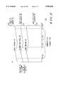
- FIG. 1illustrates a block diagram of a communication system for use in accordance with the present invention.
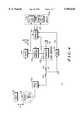
- FIG. 2illustrates a block diagram of a wireless communication device in accordance with an embodiment of the present invention.
- FIG. 3illustrates a graph providing an indication of a change in an electromagnetic field versus frequency in accordance with the present invention.
- FIG. 4illustrates a block diagram of a wireless communication device in accordance with a first embodiment of the present invention.
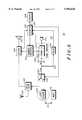
- FIG. 5illustrates a block diagram of a wireless communication device in accordance with a second embodiment of the present invention.
- FIG. 6illustrates a block diagram of a wireless communication device in accordance with a third embodiment of the present invention.
- FIG. 7illustrates a block diagram of a wireless communication device in accordance with a fourth embodiment of the present invention.
- FIG. 1is a block diagram of a communication system 100 for use in accordance with a the present invention.
- the communication system of FIG. 1generally comprises a wireless communication system 102 coupled to a wireline communication system 104.
- the wireless communication system 102generally comprises a switch 113 coupled to a plurality of remote stations 107, 109 and 111, and a plurality of wireless communication devices 101, 103 and 105.
- the communication system 100provides communications between the wireline communication system 104 and one or more wireless communication devices 101, 103 and 105, or among the wireless communication devices 101, 103 and 105 in the wireless communication network 102.
- the wireline communication network 104is a public switched telephone network.
- the remote stations 107, 109 and 111, the switch 113 and the wireline communication network 104are individually well known in the art, and hence no additional description is needed here except as may be necessary to facilitate the understanding of the present invention.
- the wireless communication system 102is a radiotelephone system, and in particular, a cellular radiotelephone system.
- the wireless communication system 102may comprise a cordless radiotelephone system, a satellite communication system, a paging system, a trunked radio system, a personal communication system (PCS), and the like.
- the wireline communication network 104need not be implemented in all of the alternative mentioned wireless communication systems, as is well known in the art. For example, all communications may be only wireless.
- the wireless communication devices 101, 103 and 105are radio subscriber units 101, 103 and 105, and in particular, cellular radiotelephone subscriber units.
- the wireless communication devices 101, 103 and 105may comprise cordless radiotelephones, pagers, one-way radios, two-way radios, personal data assistants, personal notebooks, remote controllers, and the like.
- the wireless communication devices 101, 103 and 105are portable devices that operate in a wireless communication system 102 to advantageously provide users of the devices 101, 103 and 105 with portable communications.
- the portable deviceis easily carried by a user and transferable to a battery charger, a holster, a hang-up cup, a vehicular adapter, and the like, as is well known in the art.
- the wireless communication devices 101, 103 and 105communicate with one of the plurality of remote stations 107, 109 and 111 via electromagnetic signals 121, 123 and 125 such as those in the radio frequency (RF) range, for example.
- the radio frequency signals 121, 123 and 125are radiotelephone calls transmitted and received by the radiotelephones 101, 103 and 105, respectively,.
- the wireless communication devices 101, 103 and 105may communicate voice only, data only, video or any combination thereof.
- the modulation of the electromagnetic signals communicated between the wireless communication devices 101, 103 and 105 and the fixed sites 107, 109 and 111may be either analog or digital.
- the electromagnetic signals 121, 123 and 125may be infra-red signals or any other signal capable of communicating information in a wireless environment.
- the remote stations 107, 109 and 111are land-base stations.
- the wireless communication devices 101, 103 and 105communicate with the remote stations 107, 109 and 111 which, in turn, couple two-way communication through the switch 113.
- Each of the remote stations 107, 109 and 111have a transmitter and/or a receiver.
- Remote station 107for example, has a transmitter 110 and a receiver 108.
- the remote stations 107, 109 and 111provide communications, throughout discrete radio coverage areas 115, 117, and 119, respectively, enabling the wireless communication devices 101, 103 and 105 to communicate with the wireless communication system 102 over predetermined geographic areas.
- the predetermined geographic areasrepresent cellular macro-cells.
- the predetermined geographic areas 115. 117, 119represent cellular mini-cells or micro-cells, as is well known in the art.
- the remote stations 107, 109 and 111may alternatively comprise satellites orbiting about the earth to communicate either directly with the wireless communication devices 101, 103 and 105 or through other land-base stations.
- the remote stations 107, 109 and 111may comprise cordless base stations in a cordless radiotelephone system.
- the remote stations 107, 109 and 111may comprise paging transmission and/or reception stations in a paging system.
- the switch 113is a telephone exchange, and in particular, a cellular telephone exchange.
- the switch 113may be a cordless telephone exchange such as used in PCS systems.
- the switch 113performs operations of call placement, control, interconnection with the wireline communication network 104, and the like.
- FIGS. 2 and 4-7illustrate block diagrams of a wireless communication device 101, for example, according to various embodiments of the present invention.
- FIG. 3illustrates a graph for supporting additional discussion relevant to the operation of FIG. 2.
- FIGS. 2 and 3provide a broad overview of a preferred embodiment of the present invention.
- FIGS. 4 and 5illustrate block diagrams of preferred embodiments of the wireless communication device 101 primarily having a transmitter, such as in a radiotelephone, for example.
- FIGS. 6 and 7illustrate block diagrams of preferred embodiments of the wireless communication device 101 primarily having a receiver, such as in a pager, for example. All of the discussion for the wireless communication device 101 in FIGS. 2 and 3 also applies to the embodiments of FIGS.
- FIG. 2illustrates a block diagram of a wireless communication device 101, for example, in accordance with the present invention.
- the wireless communication device 101is adapted for communicating with a remote station 107.
- the wireless communication device 101comprises a signal generator 200, a radiator 202, a sensor 204, a controller 206 and circuitry 208.
- the signal generator 200generates a forward signal 210 on line 211.
- the radiator 202coupled to the signal generator 200, radiates the forward signal 210 to produce an electromagnetic field 212 near the radiator 202.
- the electromagnetic field 212changes by a predetermined amount responsive to the proximity 214 of the radiator 202 to a predetermined object 216 external to the wireless communication device 101.
- the sensor 204coupled to the radiator 202, provides an indication 218 of the predetermined amount of change in the electromagnetic field 212.
- the controller 206coupled to the sensor 204, controls the circuitry 208 in the wireless communication device 101 responsive to the indication 218 of the predetermined amount of change in the electromagnetic field 212.
- the signal generator 200has an output terminal 220 providing the forward signal 210.
- the radiator 202has an input terminal 222.
- the input terminal 222 of the radiator 202is coupled to the output terminal 220 of the signal generator 200.
- the radiator 202radiates the forward signal 210 to produce the electromagnetic field 212 near the radiator 202.
- the electromagnetic field 212changes by the predetermined amount responsive to the proximity 214 of the radiator 202 to the predetermined object external 216 to the wireless communication device 101.
- the sensor 204has an input terminal 224 and an output terminal 226.
- the input terminal 224 of the sensor 204is coupled to the input terminal 222 of the radiator 202.
- the output terminal 226 of the sensor 204provides the indication 218 of the predetermined amount of change in the electromagnetic field 212.
- the controller 206has an input terminal 228 and an output terminal 230.
- the input terminal 228 of the controller 206is coupled to the output terminal 226 of the sensor 204.
- the output terminal 230 of the controller 206controls the circuitry 208 in the wireless communication device 101 responsive to the indication 218 of the predetermined amount of change in the electromagnetic field 212.
- the predetermined object 216 external to the wireless communication device 101is a portion of a human body 232.
- the predetermined object 216 external to the wireless communication device 101may be an element of a battery charger 234 adapted to charge a battery of the wireless communication device 101, an element of a hang-up cup 236 adapted to receive the wireless communication device 101, an element of a portable holster 238 adapted for carrying the wireless communication device 101, an element of a vehicular adapter 240 adapted for receiving the wireless communication device and the like.
- These objectsrepresent, by example, many of the objects that the wireless communication device 101 normally encounters during operation.
- the electromagnetic wave proximity sensor 201can replace or be used in conjunction with conventional proximity detection devices such as reed switches, mechanical switches, Hall-effect switches, and the like.
- the electromagnetic wave proximity detector 201is operated at times in accordance with initial design decisions. For example, the electromagnetic wave proximity detector 201 may operate periodically to periodically check for the presence of the object. Alternatively, the electromagnetic wave proximity detector 201 may be operated at predetermined times based on other operations of the controller 206. For example, the electromagnetic wave proximity detector 201 may operate when the wireless communication device 101 is being paged, while the wireless communication device 101 is in a call, and/or when the wireless communication device 101 is not in a call.
- the electromagnetic wave proximity detector 201may have a sensitivity level adjustment associated therewith permitting a user to adjust its sensitivity accordingly. This feature would be particularly useful when the object 216 is the human body 232. Therefore, the user could adjust the proximity detector's sensitivity to account for the location of the wireless communication device 101 on the user's body, the type of clothes being worn by the user, and the like.
- an element thereinwould provide an accurate target permitting the electromagnetic wave proximity detector 201 to accurately detect the location of the object near the electromagnetic field 212. Accurate detection is possible in these conditions because the design variables are predetermined. Therefore, in these types of application, the sensitivity level of the electromagnetic wave proximity detector 201 would typically be fixed.
- electromagnetic wave proximity detector 201may be adjustable to accurately detect the human body and fixed to detect an element of the objects 234, 236, 238 and 240.
- the electromagnetic wave proximity detector 201can activate two different sensing programs at different times to check for the different objects under different conditions.
- the radiator 202produces a reflected signal 242 on line 211 responsive to receiving the forward signal 210 on line 211.
- the reflected signal 242is typically produced due to a mismatch between the signal generator 200 and the radiator 202, as is well known in the art.
- the sensor 204provides the indication 218 of the predetermined amount of change in the electromagnetic field 212 responsive to at least one parameter of the forward signal 210 and at least one parameter of the reflected signal 242.
- the senor 204further comprises a signal sampler 246 and a signal detector 248.
- the signal sampler 246is a bidirectional coupler 254 having a first port 256 for sampling the reflected signal 242 on line 211 and having a second port 258 for sampling the forward signal 210 on line 211.
- Bi-directional couplersare generally well known in the art and will not be discussed in further detail.
- the at least one parameter of the forward sampled signal 252 and at least one parameter of the reflected sampled signal 250each include magnitude and phase.
- the signal detector 248further comprises a reflected magnitude detector 260, a reflected phase detector 262, a forward magnitude detector 264, and a forward phase detector 266.
- the reflected magnitude detector 260detects the magnitude of the reflected sampled signal 250.
- the reflected phase detector 262detects the phase of the reflected sampled signal 250.
- the forward magnitude detector 264detects the magnitude of the forward sampled signal 252.
- the forward phase detector 266detects the phase of the forward sampled signal 252.
- a detected magnitude of the reflected sampled signal 268, a detected phase of the reflected sampled signal 270, a detected magnitude of the forward sampled signal 272, and a detected phase of the forward sampled signal 274provide the indication 218 of the predetermined amount of change in the electromagnetic field 212.
- the reflected magnitude detector 260, the reflected phase detector 262, the forward magnitude detector 264, and the forward phase detector 266are implemented using conventional diode circuits.
- the reflected and forward magnitude detectors 260 and 264use a single diode as an envelope detector.
- the reflected and forward phase detectors 262 and 266use a bridge type diode arrangement.
- Other implementations for magnitude and phase detectorsmay be implemented as well known to those skilled in the art.
- the sensor 204may alternatively comprise a circuit to detect changes in an electric field of one radiator and a magnetic field of another radiator.
- a radiator 276 producing electromagnetic field 278is also shown in FIG. 2 in dotted lines.
- the dotted linesrepresent the radiator 278 as an alternative implementation for use with the wireless communication device 101.
- the second radiator 276, coupled to the signal generator 200,radiates the forward signal 210 at line 211 to produce the electromagnetic field 278.
- the electromagnetic field 278changes by a predetermined amount responsive to the proximity 280 of the second radiator 276 to the predetermined object 216 external to the wireless communication device 101.
- the sensor 204coupled to the first radiator 202 and the second radiator 276, provides an indication 218 of the predetermined amount of change in the electromagnetic field 212 of the first radiator 202 and the predetermined amount of change in the electromagnetic field 278 of the second radiator 276.
- the indication 218 of the predetermined amount of change in the electromagnetic field 212 of the first radiator 202is responsive to a change in an electric field 212 of the first radiator 202.
- the indication 218 of the predetermined amount of change in the electromagnetic field 278 of the second radiator 276is responsive to a change in a magnetic field of the second radiator 276.
- the first radiator 202 and the second radiator 276may be antenna elements of a diversity receiver structure. Alternatively, the first radiator 202 and/or the second radiator 276 may be used solely for the purpose of implementing the electromagnetic proximity wave sensor 201.
- a wireless communication device 101is adapted for communicating with a remote base station 107.
- the wireless communication device 101comprises the signal generator 200, the radiator 202, the bi-directional coupler 254, the signal detector 248 and the controller 206.
- the signal generator 200generates the forward signal 210.
- the radiator 202coupled to the signal generator 200, radiates the forward signal 210 to produce an electromagnetic field 212 near the radiator 202.
- the electromagnetic field 212changes by a predetermined amount responsive to the proximity 214 of the radiator 202 to the predetermined object 216 external to the wireless communication device 101.
- the radiator 202produces a reflected signal 242 responsive to receiving the forward signal 210.
- the bi-directional coupler 254coupled to the radiator 202, has a first port 256 for sampling the reflected signal 242 and has a second port 258 for sampling the forward signal 210 to produce a reflected sampled signal 250 and a forward sampled signal 252, respectively.
- the controller 206coupled to the signal detector 148, controls circuitry 208 in the wireless communication device 101 responsive to the detected magnitude and phase of the reflected sampled signal 250 and the detected magnitude and phase of the forward sampled signal 252.
- FIG. 3illustrates a graph 300 plotting the indication 218 of a change in an electromagnetic field 212 versus frequency 302 in accordance with the present invention.
- the graph 300represents how the controller 206 evaluates the information 218 provided by the sensor 204.
- the graph 300includes an upper predetermined threshold 304, a free space reference 306 and a lower predetermined threshold 308.
- the indication 218 of the predetermined amount of change in the electromagnetic field 212is desirable when it is outside a predetermined range of values 310 and is undesirable when it is inside the predetermined range of values 310.
- the changeis desirable when the object 216 is near to the radiator 202 (shown at 306 and 308), thereby causing the predetermined amount of change in the electromagnetic field 212.
- the changeis undesirable when the object 216 is far from the radiator 202 (shown at 310), thereby not causing the predetermined amount of change in the electromagnetic field 212.
- the indication 218 of the change in the electromagnetic field 212changes with the frequency 302 of the forward signal 210 at line 211.
- the representation of the change in the electromagnetic field 212 over the frequency in FIG. 3is only a sample of many variations that may be possible.
- the change is the electromagnetic field 212 over frequency 302depends upon the nature of the radiator 202, the nature of the object 216, a transmit or receive frequency band, the orientation between the radiator 202 and the object 216, the distance between the radiator 202 and the object 216, and the like. These factors need to be considered when designing the electromagnetic wave proximity detector 201 into the wireless communication device 101.
- the signal generator 200may generate the forward signal 210 at two different frequencies 312 and 314 in order for the sensor 204 to more accurately detect the indication 218 of the change in the electromagnetic field 212. Since there would typically be only one signal generator 200, the signal generator 200 would generate the forward signal 210 at a first frequency 312 at a first point in time and at a second frequency 314 at a second point in time.
- the radiator 202produces a reflected signal 242 at the first frequency 312 at the first point in time and at the second frequency 314 at the second point in time responsive to receiving the forward signal 210 generated at the first frequency 312 at the first point in time and at the second frequency 314 at the second point in time, respectively.
- the sensor 204provides the indication 218 of the predetermined amount of change in the electromagnetic field 212 responsive to the first frequency 312 and the second frequency 314 of the forward signal 210 and the first frequency 312 and the second frequency 314 of the reflected signal 242. Taking the measurements at two frequencies may be performed by the controller 206 alone or in combination with the range detection represented by the three thresholds 304, 306 and 308. Sampling the reflected signal 242 at two frequencies 312 and 314 increases the likelihood of a valid detection given the variation in the change in the electromagnetic field 212 over frequency 302.
- the forward signal 210is generated at the first frequency 312 at the first point in time on a control channel and the forward signal is generated at the second frequency 314 at the second point in time on a voice channel.
- the control channel and the voice channelrepresents one method of implementing the two frequency detection scheme. This method is preferred in a cellular radiotelephone application because the control channel is naturally on a different frequency than the voice channel during transmission of the forward signal 210.
- a further advantage of this method in a cellular radiotelephone applicationis that the switch between the control channel and the voice channel typically happens when the cellular radiotelephone is being paged by the cellular radiotelephone system. Therefore the electromagnetic wave proximity sensor 201 can operate before the cellular radiotelephone starts to ring to alert the user of an incoming call.
- the predetermined amount of change in the electromagnetic field 212is calibrated responsive to generating the forward signal 210 over a predetermined frequency band 320.
- the calibrationis performed during the initial design process.
- the calibrationmay be performed during the manufacture of the wireless communication device 101. This may be necessary due to the variation among components in a transmission lineup for each individual wireless communication device.
- FIG. 4illustrates a block diagram of a wireless communication device in accordance with a first embodiment of the present invention.
- the wireless communication device 101configured as a radiotelephone in the preferred embodiment, generally comprises an antenna 408, a duplexer 406, a receiver 404, a transmitter 402, a speaker 412, a microphone 414, a frequency synthesizer 410, the controller 206, a tactile alert device 416, and an audible alert device 418.
- the antenna 408, the duplexer 406, the receiver 404, the transmitter 402, the speaker 412, the microphone 414, the frequency synthesizer 410, the tactile alert device 416, and the audible alert device 418are each individually well known in the art, and hence no additional description need be given except as may be necessary to facilitate the understanding of the present invention. Further, the general operation of a radiotelephone is well known in the art and will not be described except as may be necessary to facilitate the understanding of the present invention.
- the audible alert device 418is a ringer.
- the audible alert device 418is operable to generate an audible alert when enabled by the controller 206.
- the tactile alert device 416is a vibrator.
- the tactile alert device 416is operable to generate a tactile alert when enabled by the controller 206.
- the signal generator 200is a radio frequency (RF) transmitter 402 for generating the forward signal 210 as a transmitted signal at a radio frequency.
- RFradio frequency
- the preferred transmit operating frequency bandis 824 MHz to 845 MHz.
- the forward signal 210is a communication signal including at least one of a voice signal and a data signal.
- the forward signal 210is generated as part of the radiotelephone's normal transmission during the set up or while in a phone call.
- the forward signal 210may be generated solely for the purpose of taking a proximity measurement, thereby not being related a phone call.
- the radiator 202is a monopole antenna 408 tuned to the operating frequency of 824 MHz to 845 MHz.
- the antenna 408is a tightly wound helical, normal mode antenna. However, any antenna construction may be used which would transmit in the desirable frequency band.
- the antenna 408forms the radiator 202.
- RFradio frequency
- the electromagnetic field 212changes by a predetermined amount responsive to the proximity 214 of the antenna 408 to the predetermined object 216 external to the radiotelephone.
- the sensor 204coupled to the antenna 408, provides an indication 218 of the predetermined amount of change in the electromagnetic field 212.
- the controller 206coupled to the sensor 204, controls the circuitry 208 in the radiotelephone 101 responsive to the indication 218 of the predetermined amount of change in the electromagnetic field 212.
- the electromagnetic field 212is a near field structure as opposed to a plain wave structure.
- the difference between these two structuresis well known in the art.
- the near fieldextends a few inches from the antenna 408. Therefore, at the preferred transmit frequency range of a cellular radiotelephone, the object 216 needs to come within a few inches of the antenna 408 in order for the sensor 204 to properly detect the object 216 within the electromagnetic field 212.
- a primary advantage of implementing an electromagnetic wave proximity detector 201 in a radiotelephoneis the high degree of integration among parts and functions of the radiotelephone.
- all of the parts of the proximity detector 201, including the transmitter 402, the antenna 408, the bidirectional coupler 254, the forward magnitude detector 264 of the signal detector 248 and the controllerare already implemented in the radiotelephone to perform traditional radiotelephone transmit functions, such as making a phone call.
- the bi-directional coupler 254 and the forward magnitude detector 264are used by radiotelephones for transmit power control, as is well known in the art.
- the parameters of the reflected signal 242can be compared against the parameters of the forward signal 210 to determine if there is a predetermined change in the electromagnetic field 212 due to the presence of the predetermined object.
- a traditional radiotelephonehas incorporated therein the parts needed to implement the electromagnetic wave proximity detector 201.
- the electromagnetic wave proximity detector 201preferably operates while the radiotelephone is transmitting a communication signal in a traditional fashion. Therefore, while the radiotelephone is setting up a call or in a call, the electromagnetic wave proximity detector 201 is operating. Alternatively, the electromagnetic wave proximity detector 201 may operate when the radiotelephone is not transmitting a communication signal. Using this method the transmitter would typically transmit the forward signal 210 at low power level so as not to interfere with the operation of the wireless communication system 202.
- the radiotelephone 101is adapted for communicating with a remote base station 107.
- the radiotelephone 101comprises the transmitter 402, the antenna 408, the bi-directional coupler 254, the signal detector 248 and the controller 206.
- the transmitter 402generates the forward signal 210 at the radio frequency.
- the forward signal 210is the communication signal including at least one of the voice signal and the data signal.
- the antenna 408, coupled to the transmitter 402,radiates the forward signal 210 at the radio frequency to produce an electromagnetic field 212 near the antenna 408 and to communicate with the remote RF receiver 108 adapted to receive the forward signal 210.
- the electromagnetic field 212changes by a predetermined amount responsive to the proximity 214 of the antenna 408 to a predetermined object 216 external to the radiotelephone 101.
- the antenna 408produces a reflected signal 242 responsive to receiving the forward signal 210.
- the bi-directional coupler 254, coupled to the antenna 408,has a first port 256 for sampling the reflected signal 242 and has a second port 258 for sampling the forward signal 210 to produce a reflected sampled signal 250 and a forward sampled signal 252, respectively.
- the controller 206coupled to the signal detector 248, controls circuitry 208 in the radiotelephone 101 responsive to the detected magnitude 268 and phase 270 of the reflected sampled signal 250 and the detected magnitude 272 and phase 274 of the forward sampled
- FIG. 5illustrates a block diagram of the radiotelephone 101 in accordance with a second embodiment of the present invention.
- the radiotelephone 101further comprises another radiator 502 and a switch 500.
- the antenna 408performs the traditional function of radiating the forward signal 210 at the radio frequency to communicate with the remote RF receiver 108 adapted to receive the forward signal 210.
- the radiator 502performs the additional function of proximity detection.
- the switch 500coupled to the transmitter 402, the antenna 408 and the radiator 502, selectively couples the transmitter 402 to the antenna 408 or the radiator 502.
- the controller 206controls the switch 500 to alternatively transmit a communication signal and sense the proximity of the object 216.
- the switchmay be eliminated wherein the transmitter 402, the duplex filter 406 and the radiator 502 are directly connected so that the proximity detector operates when a communication signal is transmitted.
- the radiator 502may be designed and located for optimal operation as a proximity detector.
- the radiator 502would typically be located within a housing of the radiotelephone.
- FIG. 6illustrates a block diagram of a wireless communication device 100 in accordance with a third embodiment of the present invention.
- the wireless communication device 100is a pager.
- the pager 101comprises a receiver 600, a receive filter 608, a local oscillator, a switch 606 and an antenna 610.
- the signal generator 200is a local oscillator 604 for generating the forward signal 210 at a predetermined frequency.
- the radiator 202is the antenna 610.
- the RF receiver 600coupled to the local oscillator 604 and the antenna 610, receives signals from the antenna 610 responsive to the predetermined frequency of the forward signal 210.
- the switch 606coupled to the local oscillator 604 and the antenna 610, selectively couples the local oscillator 604 to the antenna 610.
- the switch 606permits the forward signal 210 to by pass the receive filter 608 to reach the antenna 610.
- the switch 606is controlled by the controller 606 at line 614.
- a traditional pagercan having incorporated therein the electromagnetic wave proximity sensor 201. With the switch 606 in place, the pager can only operate the proximity detector 201 when the pager is not receiving a page.
- FIG. 7illustrates a block diagram of a wireless communication device in accordance with a fourth embodiment of the present invention.
- the pager 101further comprises the radiator 202 and the switch 606.
- the antenna 610performs the traditional function of receiving signals at the radio frequency to communicate with the remote RF transmitter 110.
- the RF receiver 600coupled to the local oscillator 604, and the antenna 610, receives signals from the antenna 610 responsive to the predetermined frequency of the forward signal 210.
- the radiator 202performs the additional function of proximity detection.
- the switch 606, coupled to the local oscillator 604, the antenna 610 and the radiator 202selectively couples the local oscillator 604 to the antenna 610 or the radiator 202.
- the controller 206controls the switch 606 to alternatively receive a communication signal and sense the proximity of the object 216.
- the switch 606may be eliminated wherein the receiver 600, the local oscillator 604, the receive filter 608 and the radiator 202 are directly connected so that the proximity detector operates when the local oscillator is generating the forward signal 210.
- the radiator 202provide advantages not realized by having only the antenna 610 as implemented in FIG. 5.
- the traditional antenna design and locationmay not provide the best operation as a proximity detector.
- the radiator 202may be designed and located for optimal operation as a proximity detector.
- the radiator 202would typically be located within a housing of the pager.
Landscapes
- Engineering & Computer Science (AREA)
- Physics & Mathematics (AREA)
- Computer Networks & Wireless Communication (AREA)
- Electromagnetism (AREA)
- General Physics & Mathematics (AREA)
- Signal Processing (AREA)
- Transmitters (AREA)
Abstract
Description
Claims (123)
Priority Applications (1)
| Application Number | Priority Date | Filing Date | Title |
|---|---|---|---|
| US08/656,823US5956626A (en) | 1996-06-03 | 1996-06-03 | Wireless communication device having an electromagnetic wave proximity sensor |
Applications Claiming Priority (1)
| Application Number | Priority Date | Filing Date | Title |
|---|---|---|---|
| US08/656,823US5956626A (en) | 1996-06-03 | 1996-06-03 | Wireless communication device having an electromagnetic wave proximity sensor |
Publications (1)
| Publication Number | Publication Date |
|---|---|
| US5956626Atrue US5956626A (en) | 1999-09-21 |
Family
ID=24634728
Family Applications (1)
| Application Number | Title | Priority Date | Filing Date |
|---|---|---|---|
| US08/656,823Expired - LifetimeUS5956626A (en) | 1996-06-03 | 1996-06-03 | Wireless communication device having an electromagnetic wave proximity sensor |
Country Status (1)
| Country | Link |
|---|---|
| US (1) | US5956626A (en) |
Cited By (113)
| Publication number | Priority date | Publication date | Assignee | Title |
|---|---|---|---|---|
| GB2349304A (en)* | 1999-02-24 | 2000-10-25 | Nec Corp | Portable terminal switches its call alert mode when inserted into a holder |
| US6240176B1 (en)* | 1998-06-18 | 2001-05-29 | Sony Electronics, Inc. | Method to alert a phone operator by magnetic means of an incoming call |
| US6339695B1 (en)* | 1999-05-05 | 2002-01-15 | Radioshack Corporation | Cordless phone data transfer |
| US20020010008A1 (en)* | 2000-06-30 | 2002-01-24 | Stephan Bork | Wireless communication device having intelligent alerting system |
| US20020102974A1 (en)* | 2001-01-26 | 2002-08-01 | Raith Alex Krister | Method for mating a mobile terminal with a cordless phone system |
| US6456856B1 (en)* | 1998-07-28 | 2002-09-24 | Koninklijke Philips Electronics N.V. | Mobile radio equipment forming antenna pattern to project user from radiation |
| US20020176546A1 (en)* | 2001-05-24 | 2002-11-28 | Mitsubishi Electric Research Laboratories, Inc. | Real-time audio buffering for telephone handsets |
| US6493550B1 (en)* | 1998-11-20 | 2002-12-10 | Ericsson Inc. | System proximity detection by mobile stations |
| US20030062907A1 (en)* | 2001-09-28 | 2003-04-03 | Siemens Information And Communication Mobile Llc | System and method for detecting the proximity of a body |
| US20030064761A1 (en)* | 2001-09-28 | 2003-04-03 | Siemens Information And Communication Mobile Llc | System and method for reducing SAR values |
| US20030068020A1 (en)* | 1999-01-29 | 2003-04-10 | Ameritech Corporation | Text-to-speech preprocessing and conversion of a caller's ID in a telephone subscriber unit and method therefor |
| US20030076168A1 (en)* | 2001-10-22 | 2003-04-24 | Tim Forrester | Systems and methods for controlling output power in a communication device |
| US6651651B1 (en)* | 1998-08-28 | 2003-11-25 | Smithkline Beecham Corporation | Dispenser |
| US20040127198A1 (en)* | 2002-12-30 | 2004-07-01 | Roskind James A. | Automatically changing a mobile device configuration based on environmental condition |
| US20040127197A1 (en)* | 2002-12-30 | 2004-07-01 | Roskind James A. | Automatically changing a mobile device configuration |
| US20040157648A1 (en)* | 2000-02-25 | 2004-08-12 | Charmed Technology, Inc. | Wearable computing device capable of responding intelligently to surroundings |
| US20040204000A1 (en)* | 2002-05-30 | 2004-10-14 | Aaron Dietrich | Mobile communication device including an array sensor |
| WO2005093453A1 (en)* | 2004-03-25 | 2005-10-06 | Wimcare Interactive Medicine Inc. | Private location detection system |
| US20050221791A1 (en)* | 2004-04-05 | 2005-10-06 | Sony Ericsson Mobile Communications Ab | Sensor screen saver |
| US7007558B1 (en) | 2002-05-24 | 2006-03-07 | Lake Charles Instruments, Inc. | Pulse transmitter |
| US20060073819A1 (en)* | 2004-10-04 | 2006-04-06 | Research In Motion Limited | Automatic audio intensity adjustment |
| US20060084480A1 (en)* | 2004-10-14 | 2006-04-20 | Motorola, Inc. | Apparatus and method for stimulating one or more areas on a wearer |
| US20060101596A1 (en)* | 2004-11-12 | 2006-05-18 | Smartpool, Inc. | Wheel arrangement for swimming pool cleaner |
| US20060128439A1 (en)* | 2004-12-13 | 2006-06-15 | Lg Electronics Inc. | Method for automatically switching incoming call signal output mode from vibration to ringtone using vibration detection unit in mobile communication terminal |
| US20060212585A1 (en)* | 2002-02-08 | 2006-09-21 | Eaton Eric T | System for providing continuity between session clients and method therefor |
| US7209753B2 (en) | 2000-09-07 | 2007-04-24 | Ericsson Inc. | Method to control the update frequency of a positioning device by a mobile terminal |
| US20070120874A1 (en)* | 2003-04-25 | 2007-05-31 | Macinnis Alexander G | Graphics display system with line buffer control scheme |
| US20070236497A1 (en)* | 2002-10-18 | 2007-10-11 | Sony Corporation | Information processing system and method, information processing apparatus, image-capturing device and method, recording medium, and program |
| US20070281614A1 (en)* | 2006-06-01 | 2007-12-06 | Motorola, Inc. | Method and apparatus for dual mode communications |
| US20070293188A1 (en)* | 2006-06-20 | 2007-12-20 | Philip John Houghton | Method and system for an audio speaker with proximity sensing |
| US20080051165A1 (en)* | 2006-08-28 | 2008-02-28 | Motorola, Inc. | Rf power control using proximity sensor |
| US20080122919A1 (en)* | 2006-11-27 | 2008-05-29 | Cok Ronald S | Image capture apparatus with indicator |
| US20080165002A1 (en)* | 2005-01-07 | 2008-07-10 | Optex Co., Ltd. | Microwave Sensor |
| US20090143113A1 (en)* | 2001-09-28 | 2009-06-04 | Agere Systems Incorporated | portable cell phone and a proximity regulation system for use with a portable cell phone |
| US20090284245A1 (en)* | 2008-05-13 | 2009-11-19 | Qualcomm Incorporated | Wireless power transfer for appliances and equipments |
| US20090305742A1 (en)* | 2008-06-05 | 2009-12-10 | Ruben Caballero | Electronic device with proximity-based radio power control |
| US20090311941A1 (en)* | 2005-06-18 | 2009-12-17 | Jkid Limited | Portable Device |
| US20100159829A1 (en)* | 2008-12-23 | 2010-06-24 | Mccormack Gary D | Tightly-coupled near-field communication-link connector-replacement chips |
| US20110012793A1 (en)* | 2009-07-17 | 2011-01-20 | Amm David T | Electronic devices with capacitive proximity sensors for proximity-based radio-frequency power control |
| US20110012794A1 (en)* | 2009-07-17 | 2011-01-20 | Schlub Robert W | Electronic devices with parasitic antenna resonating elements that reduce near field radiation |
| US20110050446A1 (en)* | 2009-09-01 | 2011-03-03 | Guidance IP, Ltd. | Proximity sensors |
| US20110102266A1 (en)* | 2009-10-30 | 2011-05-05 | Dwayne Andrew Folden | Wireless proximity probe and method of operating same |
| US20110159920A1 (en)* | 2009-12-28 | 2011-06-30 | Lehmann Harry V | Method and system to minimize radiation exposure from mobile phones and devices |
| USRE42738E1 (en) | 1997-10-28 | 2011-09-27 | Apple Inc. | Portable computers |
| US20110250928A1 (en)* | 2010-04-13 | 2011-10-13 | Schlub Robert W | Adjustable wireless circuitry with antenna-based proximity detector |
| US8050665B1 (en) | 2006-10-20 | 2011-11-01 | Avaya Inc. | Alert reminder trigger by motion-detector |
| US20120052804A1 (en)* | 2010-08-27 | 2012-03-01 | Compal Electronics, Inc. | Method for controlling function and electronic device applying thereof |
| US20120071108A1 (en)* | 2010-09-20 | 2012-03-22 | Mediatek Inc. | Radio Frequency Signal Control Module and Radio Frequency Signal Controlling Method |
| KR101188664B1 (en) | 2012-02-02 | 2012-10-09 | 김영준 | Method and device for wireless communication with mobile device using magnetic field |
| WO2012174350A1 (en)* | 2011-06-15 | 2012-12-20 | Waveconnex, Inc. | Proximity sensing and distance measurement using ehf signals |
| US8412798B1 (en) | 2009-10-03 | 2013-04-02 | Frank C. Wang | Content delivery system and method |
| US8462002B2 (en) | 2010-06-18 | 2013-06-11 | The Invention Science Fund I, Llc | Personal telecommunication device with target-based exposure control |
| US8463288B2 (en) | 2010-06-18 | 2013-06-11 | The Invention Science Fund I, Llc | Irradiation self-protection from user telecommunication device |
| US20130210477A1 (en)* | 2012-02-15 | 2013-08-15 | Microchip Technology Incorporated | Proximity Detection Using an Antenna and Directional Coupler Switch |
| US8519856B2 (en) | 2010-06-18 | 2013-08-27 | The Invention Science Fund I, Llc | Mapping system for irradiation protection |
| WO2013137892A1 (en) | 2012-03-15 | 2013-09-19 | Intel Corporation | Near field co (nfc) and proximity sensor for portable devices |
| US8577289B2 (en) | 2011-02-17 | 2013-11-05 | Apple Inc. | Antenna with integrated proximity sensor for proximity-based radio-frequency power control |
| WO2013164628A1 (en)* | 2012-05-03 | 2013-11-07 | University Of Ulster | Movement detection using a portable electronic device |
| US8581735B2 (en) | 2010-07-23 | 2013-11-12 | Blackberry Limited | Warning and preparatory system for a portable device |
| CN103460163A (en)* | 2011-04-04 | 2013-12-18 | 夏普株式会社 | Display device, information processing system and program |
| US8686865B2 (en) | 2010-06-18 | 2014-04-01 | The Invention Science Fund I, Llc | Interactive technique to reduce irradiation from external source |
| US8714459B2 (en) | 2011-05-12 | 2014-05-06 | Waveconnex, Inc. | Scalable high-bandwidth connectivity |
| US8794980B2 (en) | 2011-12-14 | 2014-08-05 | Keyssa, Inc. | Connectors providing HAPTIC feedback |
| US8804945B1 (en)* | 2005-11-17 | 2014-08-12 | Securus Technologies, Inc. | Detecting events occurring on remote telephone |
| US8811526B2 (en) | 2011-05-31 | 2014-08-19 | Keyssa, Inc. | Delta modulated low power EHF communication link |
| US8854224B2 (en) | 2009-02-10 | 2014-10-07 | Qualcomm Incorporated | Conveying device information relating to wireless charging |
| US8878393B2 (en) | 2008-05-13 | 2014-11-04 | Qualcomm Incorporated | Wireless power transfer for vehicles |
| US8909135B2 (en) | 2011-09-15 | 2014-12-09 | Keyssa, Inc. | Wireless communication with dielectric medium |
| US8929834B2 (en) | 2012-03-06 | 2015-01-06 | Keyssa, Inc. | System for constraining an operating parameter of an EHF communication chip |
| US8938497B1 (en) | 2009-10-03 | 2015-01-20 | Frank C. Wang | Content delivery system and method spanning multiple data processing systems |
| US9093745B2 (en) | 2012-05-10 | 2015-07-28 | Apple Inc. | Antenna and proximity sensor structures having printed circuit and dielectric carrier layers |
| US9125144B1 (en)* | 2006-10-20 | 2015-09-01 | Avaya Inc. | Proximity-based feature activation based on programmable profile |
| WO2015152887A1 (en)* | 2014-03-31 | 2015-10-08 | Hewlett-Packard Development Company, L.P. | Adjusting transmitted power output of an antenna of a device |
| US9191263B2 (en) | 2008-12-23 | 2015-11-17 | Keyssa, Inc. | Contactless replacement for cabled standards-based interfaces |
| US9203597B2 (en) | 2012-03-02 | 2015-12-01 | Keyssa, Inc. | Systems and methods for duplex communication |
| US9219956B2 (en) | 2008-12-23 | 2015-12-22 | Keyssa, Inc. | Contactless audio adapter, and methods |
| US9270769B1 (en)* | 2004-08-11 | 2016-02-23 | Aol Inc. | Mobile communications device |
| US9300342B2 (en) | 2013-04-18 | 2016-03-29 | Apple Inc. | Wireless device with dynamically adjusted maximum transmit powers |
| US9312924B2 (en) | 2009-02-10 | 2016-04-12 | Qualcomm Incorporated | Systems and methods relating to multi-dimensional wireless charging |
| US9350799B2 (en) | 2009-10-03 | 2016-05-24 | Frank C. Wang | Enhanced content continuation system and method |
| US9374154B2 (en) | 2012-09-14 | 2016-06-21 | Keyssa, Inc. | Wireless connections with virtual hysteresis |
| US9379445B2 (en) | 2014-02-14 | 2016-06-28 | Apple Inc. | Electronic device with satellite navigation system slot antennas |
| US9379450B2 (en) | 2011-03-24 | 2016-06-28 | Keyssa, Inc. | Integrated circuit with electromagnetic communication |
| US9398456B2 (en) | 2014-03-07 | 2016-07-19 | Apple Inc. | Electronic device with accessory-based transmit power control |
| US9407311B2 (en) | 2011-10-21 | 2016-08-02 | Keyssa, Inc. | Contactless signal splicing using an extremely high frequency (EHF) communication link |
| US9426660B2 (en) | 2013-03-15 | 2016-08-23 | Keyssa, Inc. | EHF secure communication device |
| US9444425B2 (en) | 2014-06-20 | 2016-09-13 | Apple Inc. | Electronic device with adjustable wireless circuitry |
| US9474099B2 (en) | 2008-12-23 | 2016-10-18 | Keyssa, Inc. | Smart connectors and associated communications links |
| US9515365B2 (en) | 2012-08-10 | 2016-12-06 | Keyssa, Inc. | Dielectric coupling systems for EHF communications |
| US9531425B2 (en) | 2012-12-17 | 2016-12-27 | Keyssa, Inc. | Modular electronics |
| US9553616B2 (en) | 2013-03-15 | 2017-01-24 | Keyssa, Inc. | Extremely high frequency communication chip |
| US9553353B2 (en) | 2012-03-28 | 2017-01-24 | Keyssa, Inc. | Redirection of electromagnetic signals using substrate structures |
| US9559425B2 (en) | 2014-03-20 | 2017-01-31 | Apple Inc. | Electronic device with slot antenna and proximity sensor |
| US9559790B2 (en) | 2012-01-30 | 2017-01-31 | Keyssa, Inc. | Link emission control |
| US9564680B2 (en) | 2009-12-28 | 2017-02-07 | Green Swan, Inc. | Removable and Replaceable Sound Tunnel Shell |
| US9583953B2 (en) | 2009-02-10 | 2017-02-28 | Qualcomm Incorporated | Wireless power transfer for portable enclosures |
| US9583838B2 (en) | 2014-03-20 | 2017-02-28 | Apple Inc. | Electronic device with indirectly fed slot antennas |
| US9614590B2 (en) | 2011-05-12 | 2017-04-04 | Keyssa, Inc. | Scalable high-bandwidth connectivity |
| CN106687880A (en)* | 2014-09-11 | 2017-05-17 | 三星电子株式会社 | Electronic device and grip sensing method |
| US9705204B2 (en) | 2011-10-20 | 2017-07-11 | Keyssa, Inc. | Low-profile wireless connectors |
| US9728858B2 (en) | 2014-04-24 | 2017-08-08 | Apple Inc. | Electronic devices with hybrid antennas |
| US9791490B2 (en) | 2014-06-09 | 2017-10-17 | Apple Inc. | Electronic device having coupler for tapping antenna signals |
| US9853746B2 (en) | 2012-01-30 | 2017-12-26 | Keyssa, Inc. | Shielded EHF connector assemblies |
| US9954579B2 (en) | 2008-12-23 | 2018-04-24 | Keyssa, Inc. | Smart connectors and associated communications links |
| US9960820B2 (en) | 2008-12-23 | 2018-05-01 | Keyssa, Inc. | Contactless data transfer systems and methods |
| US10049801B2 (en) | 2015-10-16 | 2018-08-14 | Keyssa Licensing, Inc. | Communication module alignment |
| US10218052B2 (en) | 2015-05-12 | 2019-02-26 | Apple Inc. | Electronic device with tunable hybrid antennas |
| US10290946B2 (en) | 2016-09-23 | 2019-05-14 | Apple Inc. | Hybrid electronic device antennas having parasitic resonating elements |
| US10305196B2 (en) | 2012-04-17 | 2019-05-28 | Keyssa, Inc. | Dielectric lens structures for EHF radiation |
| US10375221B2 (en) | 2015-04-30 | 2019-08-06 | Keyssa Systems, Inc. | Adapter devices for enhancing the functionality of other devices |
| US10447068B2 (en) | 2017-04-03 | 2019-10-15 | Nxp B.V. | Power management circuit |
| US10490881B2 (en) | 2016-03-10 | 2019-11-26 | Apple Inc. | Tuning circuits for hybrid electronic device antennas |
| US11368036B2 (en) | 2020-04-28 | 2022-06-21 | Nxp B.V. | Power management circuit |
Citations (25)
| Publication number | Priority date | Publication date | Assignee | Title |
|---|---|---|---|---|
| US3173091A (en)* | 1960-08-30 | 1965-03-09 | Westinghouse Electric Corp | Microwave detector apparatus |
| US3403335A (en)* | 1965-05-19 | 1968-09-24 | Amp Inc | Dielectric constant measurement means and method utilizing frequency sweep and fixed probe |
| US4173755A (en)* | 1977-05-02 | 1979-11-06 | Butler George N | Battery-operated body capacitance intrusion alarm apparatus |
| US4237448A (en)* | 1979-04-30 | 1980-12-02 | Motorola, Inc. | Pager with escalating audio alert signal level |
| US4313118A (en)* | 1980-06-30 | 1982-01-26 | Calvin Noel M | Microwave proximity sensor |
| US4439734A (en)* | 1980-06-23 | 1984-03-27 | Weber Harold J | Metal object locator including frequency shift detector |
| US4475089A (en)* | 1982-03-31 | 1984-10-02 | Honeywell Inc. | Proximity detector |
| US4536761A (en)* | 1982-02-12 | 1985-08-20 | Nippon Electric Co., Ltd. | Radio paging receiver having display control means |
| US4652864A (en)* | 1982-07-26 | 1987-03-24 | Calvin Noel M | Microwave proximity sensor |
| US4727337A (en)* | 1987-04-24 | 1988-02-23 | Motorola, Inc. | Protection circuit for RF power amplifiers |
| US4845422A (en)* | 1986-12-24 | 1989-07-04 | General Electric Company | Microwave proximity sensor |
| US4862061A (en)* | 1986-12-24 | 1989-08-29 | General Electric Company | Microwave proximity sensor |
| US4868488A (en)* | 1987-11-27 | 1989-09-19 | Schmall Karl Heinz | Use of a dielectric microwave resonator and sensor circuit for determining the position of a body |
| US4871997A (en)* | 1987-06-30 | 1989-10-03 | Tech-Age International Corporation | Proximity sensor apparatus |
| US4879759A (en)* | 1987-01-08 | 1989-11-07 | Nec Corporation | Holding structure for a paging receiver having extra functions |
| US4904992A (en)* | 1989-03-28 | 1990-02-27 | Motorola, Inc. | Radio with message reception and ambient noise level controlled indicator |
| US4918438A (en)* | 1986-05-30 | 1990-04-17 | Nec Corporation | Paging receiver having audible and vibrator annunciating means |
| JPH0456533A (en)* | 1990-06-26 | 1992-02-24 | Nec Corp | Selective call radio receiver |
| US5097227A (en)* | 1990-10-09 | 1992-03-17 | Texas Instruments Incorporated | Microwave oscillator position sensor |
| US5109545A (en)* | 1990-02-09 | 1992-04-28 | Rose Communications, Inc. | Proximal cable-less communication system with intentional signal path |
| US5124954A (en)* | 1989-09-28 | 1992-06-23 | Staalkat B.V. | Method of, and apparatus for, detecting the position of an object |
| US5189389A (en)* | 1990-04-23 | 1993-02-23 | Motorola, Inc. | Electronic device having position selectable alert modes |
| US5227764A (en)* | 1990-11-06 | 1993-07-13 | Alpine Electronics, Inc. | Electromagnetic proximity sensor |
| US5227667A (en)* | 1989-01-10 | 1993-07-13 | Omron Corporation | Microwave proximity switch |
| US5542105A (en)* | 1994-10-07 | 1996-07-30 | Motorola, Inc. | Position sense radio carry case apparatus and method of using same |
- 1996
- 1996-06-03USUS08/656,823patent/US5956626A/ennot_activeExpired - Lifetime
Patent Citations (25)
| Publication number | Priority date | Publication date | Assignee | Title |
|---|---|---|---|---|
| US3173091A (en)* | 1960-08-30 | 1965-03-09 | Westinghouse Electric Corp | Microwave detector apparatus |
| US3403335A (en)* | 1965-05-19 | 1968-09-24 | Amp Inc | Dielectric constant measurement means and method utilizing frequency sweep and fixed probe |
| US4173755A (en)* | 1977-05-02 | 1979-11-06 | Butler George N | Battery-operated body capacitance intrusion alarm apparatus |
| US4237448A (en)* | 1979-04-30 | 1980-12-02 | Motorola, Inc. | Pager with escalating audio alert signal level |
| US4439734A (en)* | 1980-06-23 | 1984-03-27 | Weber Harold J | Metal object locator including frequency shift detector |
| US4313118A (en)* | 1980-06-30 | 1982-01-26 | Calvin Noel M | Microwave proximity sensor |
| US4536761A (en)* | 1982-02-12 | 1985-08-20 | Nippon Electric Co., Ltd. | Radio paging receiver having display control means |
| US4475089A (en)* | 1982-03-31 | 1984-10-02 | Honeywell Inc. | Proximity detector |
| US4652864A (en)* | 1982-07-26 | 1987-03-24 | Calvin Noel M | Microwave proximity sensor |
| US4918438A (en)* | 1986-05-30 | 1990-04-17 | Nec Corporation | Paging receiver having audible and vibrator annunciating means |
| US4845422A (en)* | 1986-12-24 | 1989-07-04 | General Electric Company | Microwave proximity sensor |
| US4862061A (en)* | 1986-12-24 | 1989-08-29 | General Electric Company | Microwave proximity sensor |
| US4879759A (en)* | 1987-01-08 | 1989-11-07 | Nec Corporation | Holding structure for a paging receiver having extra functions |
| US4727337A (en)* | 1987-04-24 | 1988-02-23 | Motorola, Inc. | Protection circuit for RF power amplifiers |
| US4871997A (en)* | 1987-06-30 | 1989-10-03 | Tech-Age International Corporation | Proximity sensor apparatus |
| US4868488A (en)* | 1987-11-27 | 1989-09-19 | Schmall Karl Heinz | Use of a dielectric microwave resonator and sensor circuit for determining the position of a body |
| US5227667A (en)* | 1989-01-10 | 1993-07-13 | Omron Corporation | Microwave proximity switch |
| US4904992A (en)* | 1989-03-28 | 1990-02-27 | Motorola, Inc. | Radio with message reception and ambient noise level controlled indicator |
| US5124954A (en)* | 1989-09-28 | 1992-06-23 | Staalkat B.V. | Method of, and apparatus for, detecting the position of an object |
| US5109545A (en)* | 1990-02-09 | 1992-04-28 | Rose Communications, Inc. | Proximal cable-less communication system with intentional signal path |
| US5189389A (en)* | 1990-04-23 | 1993-02-23 | Motorola, Inc. | Electronic device having position selectable alert modes |
| JPH0456533A (en)* | 1990-06-26 | 1992-02-24 | Nec Corp | Selective call radio receiver |
| US5097227A (en)* | 1990-10-09 | 1992-03-17 | Texas Instruments Incorporated | Microwave oscillator position sensor |
| US5227764A (en)* | 1990-11-06 | 1993-07-13 | Alpine Electronics, Inc. | Electromagnetic proximity sensor |
| US5542105A (en)* | 1994-10-07 | 1996-07-30 | Motorola, Inc. | Position sense radio carry case apparatus and method of using same |
Non-Patent Citations (3)
| Title |
|---|
| "Audible Message Alert With Ear Proximity Detector For Portable Handsets," by Robert Louis Breeden Motorola, Inc., Technical Developments, vol. 12, Apr. 1991, pp. 102-103. |
| Audible Message Alert With Ear Proximity Detector For Portable Handsets, by Robert Louis Breeden Motorola, Inc., Technical Developments, vol. 12, Apr. 1991, pp. 102 103.* |
| Vibrator (Silent) Alert Revert To Audible Option Using Motion Sensor, by Dan Larson, Motorola, Technical Developments, vol. 14, Dec. 1991, p. 60.* |
Cited By (236)
| Publication number | Priority date | Publication date | Assignee | Title |
|---|---|---|---|---|
| USRE42738E1 (en) | 1997-10-28 | 2011-09-27 | Apple Inc. | Portable computers |
| USRE44103E1 (en) | 1997-10-28 | 2013-03-26 | Apple Inc. | Portable computers |
| USRE46548E1 (en) | 1997-10-28 | 2017-09-12 | Apple Inc. | Portable computers |
| USRE44855E1 (en) | 1997-10-28 | 2014-04-22 | Apple Inc. | Multi-functional cellular telephone |
| USRE45559E1 (en) | 1997-10-28 | 2015-06-09 | Apple Inc. | Portable computers |
| US6240176B1 (en)* | 1998-06-18 | 2001-05-29 | Sony Electronics, Inc. | Method to alert a phone operator by magnetic means of an incoming call |
| US6456856B1 (en)* | 1998-07-28 | 2002-09-24 | Koninklijke Philips Electronics N.V. | Mobile radio equipment forming antenna pattern to project user from radiation |
| US6651651B1 (en)* | 1998-08-28 | 2003-11-25 | Smithkline Beecham Corporation | Dispenser |
| US6493550B1 (en)* | 1998-11-20 | 2002-12-10 | Ericsson Inc. | System proximity detection by mobile stations |
| US20030068020A1 (en)* | 1999-01-29 | 2003-04-10 | Ameritech Corporation | Text-to-speech preprocessing and conversion of a caller's ID in a telephone subscriber unit and method therefor |
| GB2349304A (en)* | 1999-02-24 | 2000-10-25 | Nec Corp | Portable terminal switches its call alert mode when inserted into a holder |
| US6339695B1 (en)* | 1999-05-05 | 2002-01-15 | Radioshack Corporation | Cordless phone data transfer |
| US20040157648A1 (en)* | 2000-02-25 | 2004-08-12 | Charmed Technology, Inc. | Wearable computing device capable of responding intelligently to surroundings |
| US20020010008A1 (en)* | 2000-06-30 | 2002-01-24 | Stephan Bork | Wireless communication device having intelligent alerting system |
| US6954657B2 (en) | 2000-06-30 | 2005-10-11 | Texas Instruments Incorporated | Wireless communication device having intelligent alerting system |
| US7209753B2 (en) | 2000-09-07 | 2007-04-24 | Ericsson Inc. | Method to control the update frequency of a positioning device by a mobile terminal |
| US20020102974A1 (en)* | 2001-01-26 | 2002-08-01 | Raith Alex Krister | Method for mating a mobile terminal with a cordless phone system |
| US6885869B2 (en) | 2001-01-26 | 2005-04-26 | Ericsson Inc. | Method for mating a mobile terminal with a cordless phone system |
| US6771768B2 (en)* | 2001-05-24 | 2004-08-03 | Mitsubishi Electric Research Laboratories, Inc. | Real-time audio buffering for telephone handsets |
| US20020176546A1 (en)* | 2001-05-24 | 2002-11-28 | Mitsubishi Electric Research Laboratories, Inc. | Real-time audio buffering for telephone handsets |
| US8532594B2 (en) | 2001-09-28 | 2013-09-10 | Agere Systems, Inc. | Portable cell phone and a proximity regulation system for use with a portable cell phone |
| US20030062907A1 (en)* | 2001-09-28 | 2003-04-03 | Siemens Information And Communication Mobile Llc | System and method for detecting the proximity of a body |
| US7146139B2 (en)* | 2001-09-28 | 2006-12-05 | Siemens Communications, Inc. | System and method for reducing SAR values |
| US8140128B2 (en)* | 2001-09-28 | 2012-03-20 | Agere Systems Inc. | Portable cell phone and a proximity regulation system for use with a portable cell phone |
| US20090143113A1 (en)* | 2001-09-28 | 2009-06-04 | Agere Systems Incorporated | portable cell phone and a proximity regulation system for use with a portable cell phone |
| US7053629B2 (en)* | 2001-09-28 | 2006-05-30 | Siemens Communications, Inc. | System and method for detecting the proximity of a body |
| US7511513B2 (en) | 2001-09-28 | 2009-03-31 | Siemens Communications Inc. | System and method for detecting the proximity of a body |
| US20060139034A1 (en)* | 2001-09-28 | 2006-06-29 | Siemens Information And Communication Mobile, Llc | System and method for detecting the proximity of a body |
| US20030064761A1 (en)* | 2001-09-28 | 2003-04-03 | Siemens Information And Communication Mobile Llc | System and method for reducing SAR values |
| US20030076168A1 (en)* | 2001-10-22 | 2003-04-24 | Tim Forrester | Systems and methods for controlling output power in a communication device |
| US6710651B2 (en)* | 2001-10-22 | 2004-03-23 | Kyocera Wireless Corp. | Systems and methods for controlling output power in a communication device |
| US20060212585A1 (en)* | 2002-02-08 | 2006-09-21 | Eaton Eric T | System for providing continuity between session clients and method therefor |
| US7676583B2 (en) | 2002-02-08 | 2010-03-09 | Motorola, Inc. | System for providing continuity between session clients and method therefor |
| US7007558B1 (en) | 2002-05-24 | 2006-03-07 | Lake Charles Instruments, Inc. | Pulse transmitter |
| US20040204000A1 (en)* | 2002-05-30 | 2004-10-14 | Aaron Dietrich | Mobile communication device including an array sensor |
| US20100097466A1 (en)* | 2002-10-18 | 2010-04-22 | Sony Corporation | Information processing system and method, information processing apparatus, image-capturing device and method, recording medium, and program |
| US8803969B2 (en) | 2002-10-18 | 2014-08-12 | Sony Corporation | Event monitoring report and display system |
| US20070242903A1 (en)* | 2002-10-18 | 2007-10-18 | Sony Corporation | Information processing system and method, information processing apparatus, image-capturing device and method, recording medium, and program |
| US9729836B2 (en) | 2002-10-18 | 2017-08-08 | Sony Corporation | Information processing system and method, information processing apparatus, image-capturing device and method, recording medium, and program |
| US7840284B2 (en) | 2002-10-18 | 2010-11-23 | Sony Corporation | Information processing system and associated methodology of surveillance event monitoring |
| US20080002027A1 (en)* | 2002-10-18 | 2008-01-03 | Sony Corporation | Information processing system and method, information processing apparatus, image-capturing device and method, recording medium, and program |
| US7830410B2 (en) | 2002-10-18 | 2010-11-09 | Sony Corporation | Information processing system and method, information processing apparatus, image-capturing device and method, recording medium, and program |
| US9532014B2 (en) | 2002-10-18 | 2016-12-27 | Sony Corporation | Information processing system and method, information processing apparatus, image-capturing device and method, recording medium, and program |
| US20070236497A1 (en)* | 2002-10-18 | 2007-10-11 | Sony Corporation | Information processing system and method, information processing apparatus, image-capturing device and method, recording medium, and program |
| US9648288B2 (en) | 2002-10-18 | 2017-05-09 | Sony Corporation | Information processing system and method, information processing apparatus, image-capturing device and method, recording medium, and program |
| US8072491B2 (en) | 2002-10-18 | 2011-12-06 | Sony Corporation | Information processing system and method, information processing apparatus, image-capturing device and method, recording medium, and program |
| US7605841B2 (en)* | 2002-10-18 | 2009-10-20 | Sony Corporation | Information processing system and method, information processing apparatus, image-capturing device and method, recording medium, and program |
| US10356370B2 (en) | 2002-10-18 | 2019-07-16 | Sony Corporation | Information processing system and method, information processing apparatus, image-capturing device and method, recording medium, and program |
| US20070239286A1 (en)* | 2002-10-18 | 2007-10-11 | Sony Corporation | Information processing system and method, information processing apparatus, image-capturing device and method, recording medium, and program |
| US20040127198A1 (en)* | 2002-12-30 | 2004-07-01 | Roskind James A. | Automatically changing a mobile device configuration based on environmental condition |
| US20040127197A1 (en)* | 2002-12-30 | 2004-07-01 | Roskind James A. | Automatically changing a mobile device configuration |
| US20070120874A1 (en)* | 2003-04-25 | 2007-05-31 | Macinnis Alexander G | Graphics display system with line buffer control scheme |
| WO2005093453A1 (en)* | 2004-03-25 | 2005-10-06 | Wimcare Interactive Medicine Inc. | Private location detection system |
| US20050221791A1 (en)* | 2004-04-05 | 2005-10-06 | Sony Ericsson Mobile Communications Ab | Sensor screen saver |
| US9270769B1 (en)* | 2004-08-11 | 2016-02-23 | Aol Inc. | Mobile communications device |
| US20060073819A1 (en)* | 2004-10-04 | 2006-04-06 | Research In Motion Limited | Automatic audio intensity adjustment |
| US7260420B2 (en)* | 2004-10-14 | 2007-08-21 | Motorola, Inc. | Apparatus and method for stimulating one or more areas on a wearer |
| US20060084480A1 (en)* | 2004-10-14 | 2006-04-20 | Motorola, Inc. | Apparatus and method for stimulating one or more areas on a wearer |
| US20060101596A1 (en)* | 2004-11-12 | 2006-05-18 | Smartpool, Inc. | Wheel arrangement for swimming pool cleaner |
| US7797780B2 (en)* | 2004-11-12 | 2010-09-21 | Smartpool, Inc. | Wheel arrangement for swimming pool cleaner |
| US7912509B2 (en)* | 2004-12-13 | 2011-03-22 | Lg Electronics Inc. | Method for automatically switching incoming call signal output mode from vibration to ringtone using vibration detection unit in mobile communication terminal |
| US20060128439A1 (en)* | 2004-12-13 | 2006-06-15 | Lg Electronics Inc. | Method for automatically switching incoming call signal output mode from vibration to ringtone using vibration detection unit in mobile communication terminal |
| US20080165002A1 (en)* | 2005-01-07 | 2008-07-10 | Optex Co., Ltd. | Microwave Sensor |
| US20090311941A1 (en)* | 2005-06-18 | 2009-12-17 | Jkid Limited | Portable Device |
| US7927170B2 (en)* | 2005-06-18 | 2011-04-19 | Jkid Limited | Portable device |
| US8804945B1 (en)* | 2005-11-17 | 2014-08-12 | Securus Technologies, Inc. | Detecting events occurring on remote telephone |
| US20070281614A1 (en)* | 2006-06-01 | 2007-12-06 | Motorola, Inc. | Method and apparatus for dual mode communications |
| US20070293188A1 (en)* | 2006-06-20 | 2007-12-20 | Philip John Houghton | Method and system for an audio speaker with proximity sensing |
| US20080051165A1 (en)* | 2006-08-28 | 2008-02-28 | Motorola, Inc. | Rf power control using proximity sensor |
| US8050665B1 (en) | 2006-10-20 | 2011-11-01 | Avaya Inc. | Alert reminder trigger by motion-detector |
| US9125144B1 (en)* | 2006-10-20 | 2015-09-01 | Avaya Inc. | Proximity-based feature activation based on programmable profile |
| US7986336B2 (en)* | 2006-11-27 | 2011-07-26 | Eastman Kodak Company | Image capture apparatus with indicator |
| US20080122919A1 (en)* | 2006-11-27 | 2008-05-29 | Cok Ronald S | Image capture apparatus with indicator |
| US20090286470A1 (en)* | 2008-05-13 | 2009-11-19 | Qualcomm Incorporated | Repeaters for enhancement of wireless power transfer |
| US9236771B2 (en) | 2008-05-13 | 2016-01-12 | Qualcomm Incorporated | Method and apparatus for adaptive tuning of wireless power transfer |
| US9178387B2 (en) | 2008-05-13 | 2015-11-03 | Qualcomm Incorporated | Receive antenna for wireless power transfer |
| US20090284245A1 (en)* | 2008-05-13 | 2009-11-19 | Qualcomm Incorporated | Wireless power transfer for appliances and equipments |
| US9991747B2 (en) | 2008-05-13 | 2018-06-05 | Qualcomm Incorporated | Signaling charging in wireless power environment |
| US9184632B2 (en) | 2008-05-13 | 2015-11-10 | Qualcomm Incorporated | Wireless power transfer for furnishings and building elements |
| US9190875B2 (en) | 2008-05-13 | 2015-11-17 | Qualcomm Incorporated | Method and apparatus with negative resistance in wireless power transfers |
| US8611815B2 (en) | 2008-05-13 | 2013-12-17 | Qualcomm Incorporated | Repeaters for enhancement of wireless power transfer |
| US9954399B2 (en) | 2008-05-13 | 2018-04-24 | Qualcomm Incorporated | Reverse link signaling via receive antenna impedance modulation |
| US8878393B2 (en) | 2008-05-13 | 2014-11-04 | Qualcomm Incorporated | Wireless power transfer for vehicles |
| US8487478B2 (en)* | 2008-05-13 | 2013-07-16 | Qualcomm Incorporated | Wireless power transfer for appliances and equipments |
| US8965461B2 (en) | 2008-05-13 | 2015-02-24 | Qualcomm Incorporated | Reverse link signaling via receive antenna impedance modulation |
| US20090284218A1 (en)* | 2008-05-13 | 2009-11-19 | Qualcomm Incorporated | Method and apparatus for an enlarged wireless charging area |
| US9130407B2 (en) | 2008-05-13 | 2015-09-08 | Qualcomm Incorporated | Signaling charging in wireless power environment |
| US8629650B2 (en) | 2008-05-13 | 2014-01-14 | Qualcomm Incorporated | Wireless power transfer using multiple transmit antennas |
| US8892035B2 (en) | 2008-05-13 | 2014-11-18 | Qualcomm Incorporated | Repeaters for enhancement of wireless power transfer |
| US8417296B2 (en) | 2008-06-05 | 2013-04-09 | Apple Inc. | Electronic device with proximity-based radio power control |
| US20090305742A1 (en)* | 2008-06-05 | 2009-12-10 | Ruben Caballero | Electronic device with proximity-based radio power control |
| US10236938B2 (en) | 2008-12-23 | 2019-03-19 | Keyssa, Inc. | Contactless replacement for cabled standards-based interfaces |
| US9219956B2 (en) | 2008-12-23 | 2015-12-22 | Keyssa, Inc. | Contactless audio adapter, and methods |
| US8554136B2 (en) | 2008-12-23 | 2013-10-08 | Waveconnex, Inc. | Tightly-coupled near-field communication-link connector-replacement chips |
| US9565495B2 (en) | 2008-12-23 | 2017-02-07 | Keyssa, Inc. | Contactless audio adapter, and methods |
| US9819397B2 (en) | 2008-12-23 | 2017-11-14 | Keyssa, Inc. | Contactless replacement for cabled standards-based interfaces |
| US20100159829A1 (en)* | 2008-12-23 | 2010-06-24 | Mccormack Gary D | Tightly-coupled near-field communication-link connector-replacement chips |
| US9853696B2 (en) | 2008-12-23 | 2017-12-26 | Keyssa, Inc. | Tightly-coupled near-field communication-link connector-replacement chips |
| US9525463B2 (en) | 2008-12-23 | 2016-12-20 | Keyssa, Inc. | Contactless replacement for cabled standards-based interfaces |
| US9954579B2 (en) | 2008-12-23 | 2018-04-24 | Keyssa, Inc. | Smart connectors and associated communications links |
| US9474099B2 (en) | 2008-12-23 | 2016-10-18 | Keyssa, Inc. | Smart connectors and associated communications links |
| US10965347B2 (en) | 2008-12-23 | 2021-03-30 | Keyssa, Inc. | Tightly-coupled near-field communication-link connector-replacement chips |
| US10601470B2 (en) | 2008-12-23 | 2020-03-24 | Keyssa, Inc. | Contactless data transfer systems and methods |
| US9960820B2 (en) | 2008-12-23 | 2018-05-01 | Keyssa, Inc. | Contactless data transfer systems and methods |
| US10595124B2 (en) | 2008-12-23 | 2020-03-17 | Keyssa, Inc. | Full duplex contactless communication systems and methods for the use thereof |
| US9191263B2 (en) | 2008-12-23 | 2015-11-17 | Keyssa, Inc. | Contactless replacement for cabled standards-based interfaces |
| US10588002B2 (en) | 2008-12-23 | 2020-03-10 | Keyssa, Inc. | Smart connectors and associated communications links |
| US10142728B2 (en) | 2008-12-23 | 2018-11-27 | Keyssa, Inc. | Contactless audio adapter, and methods |
| US10243621B2 (en) | 2008-12-23 | 2019-03-26 | Keyssa, Inc. | Tightly-coupled near-field communication-link connector-replacement chips |
| US8854224B2 (en) | 2009-02-10 | 2014-10-07 | Qualcomm Incorporated | Conveying device information relating to wireless charging |
| US9583953B2 (en) | 2009-02-10 | 2017-02-28 | Qualcomm Incorporated | Wireless power transfer for portable enclosures |
| US9312924B2 (en) | 2009-02-10 | 2016-04-12 | Qualcomm Incorporated | Systems and methods relating to multi-dimensional wireless charging |
| US8947305B2 (en) | 2009-07-17 | 2015-02-03 | Apple Inc. | Electronic devices with capacitive proximity sensors for proximity-based radio-frequency power control |
| US8432322B2 (en) | 2009-07-17 | 2013-04-30 | Apple Inc. | Electronic devices with capacitive proximity sensors for proximity-based radio-frequency power control |
| US8466839B2 (en) | 2009-07-17 | 2013-06-18 | Apple Inc. | Electronic devices with parasitic antenna resonating elements that reduce near field radiation |
| US20110012794A1 (en)* | 2009-07-17 | 2011-01-20 | Schlub Robert W | Electronic devices with parasitic antenna resonating elements that reduce near field radiation |
| US20110012793A1 (en)* | 2009-07-17 | 2011-01-20 | Amm David T | Electronic devices with capacitive proximity sensors for proximity-based radio-frequency power control |
| US20110050446A1 (en)* | 2009-09-01 | 2011-03-03 | Guidance IP, Ltd. | Proximity sensors |
| US8629771B2 (en)* | 2009-09-01 | 2014-01-14 | John Anderson | Proximity sensors |
| US8938497B1 (en) | 2009-10-03 | 2015-01-20 | Frank C. Wang | Content delivery system and method spanning multiple data processing systems |
| US9247001B2 (en) | 2009-10-03 | 2016-01-26 | Frank C. Wang | Content delivery system and method |
| US8412798B1 (en) | 2009-10-03 | 2013-04-02 | Frank C. Wang | Content delivery system and method |
| US9525736B2 (en) | 2009-10-03 | 2016-12-20 | Frank C. Wang | Content continuation system and method |
| US9350799B2 (en) | 2009-10-03 | 2016-05-24 | Frank C. Wang | Enhanced content continuation system and method |
| US9854033B2 (en)* | 2009-10-03 | 2017-12-26 | Frank C. Wang | System for content continuation and handoff |
| US8159396B2 (en)* | 2009-10-30 | 2012-04-17 | General Electric Company | Wireless proximity probe and method of operating same |
| US20110102266A1 (en)* | 2009-10-30 | 2011-05-05 | Dwayne Andrew Folden | Wireless proximity probe and method of operating same |
| US9564680B2 (en) | 2009-12-28 | 2017-02-07 | Green Swan, Inc. | Removable and Replaceable Sound Tunnel Shell |
| US20110159920A1 (en)* | 2009-12-28 | 2011-06-30 | Lehmann Harry V | Method and system to minimize radiation exposure from mobile phones and devices |
| US9191055B2 (en)* | 2009-12-28 | 2015-11-17 | Green Swan, Inc. | Method and system to minimize radiation exposure from mobile phones and devices |
| CN103339796A (en)* | 2010-04-13 | 2013-10-02 | 苹果公司 | Adjustable wireless circuitry with antenna-based proximity detector |
| KR20140041939A (en)* | 2010-04-13 | 2014-04-04 | 애플 인크. | Adjustable wireless circuitry with antenna-based proximity detector |
| US9179299B2 (en) | 2010-04-13 | 2015-11-03 | Apple Inc. | Adjustable wireless circuitry with antenna-based proximity detector |
| US20140206297A1 (en)* | 2010-04-13 | 2014-07-24 | Apple Inc | Adjustable Wireless Circuitry with Antenna-Based Proximity Detector |
| CN103339796B (en)* | 2010-04-13 | 2016-11-23 | 苹果公司 | Adjustable radio-circuit with proximity detector based on antenna |
| KR101417560B1 (en)* | 2010-04-13 | 2014-07-08 | 애플 인크. | Adjustable wireless circuitry with antenna-based proximity detector |
| US9071336B2 (en)* | 2010-04-13 | 2015-06-30 | Apple Inc. | Adjustable wireless circuitry with antenna-based proximity detector |
| US20110250928A1 (en)* | 2010-04-13 | 2011-10-13 | Schlub Robert W | Adjustable wireless circuitry with antenna-based proximity detector |
| US8781420B2 (en)* | 2010-04-13 | 2014-07-15 | Apple Inc. | Adjustable wireless circuitry with antenna-based proximity detector |
| US8463288B2 (en) | 2010-06-18 | 2013-06-11 | The Invention Science Fund I, Llc | Irradiation self-protection from user telecommunication device |
| US8686865B2 (en) | 2010-06-18 | 2014-04-01 | The Invention Science Fund I, Llc | Interactive technique to reduce irradiation from external source |
| US8519856B2 (en) | 2010-06-18 | 2013-08-27 | The Invention Science Fund I, Llc | Mapping system for irradiation protection |
| US8810425B2 (en) | 2010-06-18 | 2014-08-19 | The Invention Science Fund I, Llc | Travel route mapping based on radiation exposure risks |
| US8462002B2 (en) | 2010-06-18 | 2013-06-11 | The Invention Science Fund I, Llc | Personal telecommunication device with target-based exposure control |
| US8717185B2 (en) | 2010-07-23 | 2014-05-06 | Blackberry Limited | Warning and preparatory system for a portable device |
| US8581735B2 (en) | 2010-07-23 | 2013-11-12 | Blackberry Limited | Warning and preparatory system for a portable device |
| US20120052804A1 (en)* | 2010-08-27 | 2012-03-01 | Compal Electronics, Inc. | Method for controlling function and electronic device applying thereof |
| US8913953B2 (en)* | 2010-08-27 | 2014-12-16 | Compal Electronics, Inc. | Method for changing operating mode of electronic device when human presence is detected and electronic device using the method |
| US20120071108A1 (en)* | 2010-09-20 | 2012-03-22 | Mediatek Inc. | Radio Frequency Signal Control Module and Radio Frequency Signal Controlling Method |
| US8577289B2 (en) | 2011-02-17 | 2013-11-05 | Apple Inc. | Antenna with integrated proximity sensor for proximity-based radio-frequency power control |
| US9444146B2 (en) | 2011-03-24 | 2016-09-13 | Keyssa, Inc. | Integrated circuit with electromagnetic communication |
| US9379450B2 (en) | 2011-03-24 | 2016-06-28 | Keyssa, Inc. | Integrated circuit with electromagnetic communication |
| CN103460163B (en)* | 2011-04-04 | 2016-03-30 | 夏普株式会社 | Display device, information handling system and program |
| CN103460163A (en)* | 2011-04-04 | 2013-12-18 | 夏普株式会社 | Display device, information processing system and program |
| US8757501B2 (en) | 2011-05-12 | 2014-06-24 | Waveconnex, Inc. | Scalable high-bandwidth connectivity |
| US8714459B2 (en) | 2011-05-12 | 2014-05-06 | Waveconnex, Inc. | Scalable high-bandwidth connectivity |
| US10601105B2 (en) | 2011-05-12 | 2020-03-24 | Keyssa, Inc. | Scalable high-bandwidth connectivity |
| US9614590B2 (en) | 2011-05-12 | 2017-04-04 | Keyssa, Inc. | Scalable high-bandwidth connectivity |
| US11923598B2 (en) | 2011-05-12 | 2024-03-05 | Molex, Llc | Scalable high-bandwidth connectivity |
| US8811526B2 (en) | 2011-05-31 | 2014-08-19 | Keyssa, Inc. | Delta modulated low power EHF communication link |
| US9515859B2 (en) | 2011-05-31 | 2016-12-06 | Keyssa, Inc. | Delta modulated low-power EHF communication link |
| US9322904B2 (en) | 2011-06-15 | 2016-04-26 | Keyssa, Inc. | Proximity sensing using EHF signals |
| US9444523B2 (en) | 2011-06-15 | 2016-09-13 | Keyssa, Inc. | Proximity sensing using EHF signals |
| US9722667B2 (en) | 2011-06-15 | 2017-08-01 | Keyssa, Inc. | Proximity sensing using EHF signals |
| US8897700B2 (en) | 2011-06-15 | 2014-11-25 | Keyssa, Inc. | Distance measurement using EHF signals |
| WO2012174350A1 (en)* | 2011-06-15 | 2012-12-20 | Waveconnex, Inc. | Proximity sensing and distance measurement using ehf signals |
| US10381713B2 (en) | 2011-09-15 | 2019-08-13 | Keyssa, Inc. | Wireless communications with dielectric medium |
| US10707557B2 (en) | 2011-09-15 | 2020-07-07 | Keyssa, Inc. | Wireless communication with dielectric medium |
| US8909135B2 (en) | 2011-09-15 | 2014-12-09 | Keyssa, Inc. | Wireless communication with dielectric medium |
| US9787349B2 (en) | 2011-09-15 | 2017-10-10 | Keyssa, Inc. | Wireless communication with dielectric medium |
| US10027018B2 (en) | 2011-09-15 | 2018-07-17 | Keyssa, Inc. | Wireless communication with dielectric medium |
| US9705204B2 (en) | 2011-10-20 | 2017-07-11 | Keyssa, Inc. | Low-profile wireless connectors |
| US9407311B2 (en) | 2011-10-21 | 2016-08-02 | Keyssa, Inc. | Contactless signal splicing using an extremely high frequency (EHF) communication link |
| US9647715B2 (en) | 2011-10-21 | 2017-05-09 | Keyssa, Inc. | Contactless signal splicing using an extremely high frequency (EHF) communication link |
| US9197011B2 (en) | 2011-12-14 | 2015-11-24 | Keyssa, Inc. | Connectors providing haptic feedback |
| US8794980B2 (en) | 2011-12-14 | 2014-08-05 | Keyssa, Inc. | Connectors providing HAPTIC feedback |
| US10110324B2 (en) | 2012-01-30 | 2018-10-23 | Keyssa, Inc. | Shielded EHF connector assemblies |
| US9559790B2 (en) | 2012-01-30 | 2017-01-31 | Keyssa, Inc. | Link emission control |
| US9853746B2 (en) | 2012-01-30 | 2017-12-26 | Keyssa, Inc. | Shielded EHF connector assemblies |
| US10236936B2 (en) | 2012-01-30 | 2019-03-19 | Keyssa, Inc. | Link emission control |
| US9900054B2 (en) | 2012-01-30 | 2018-02-20 | Keyssa, Inc. | Link emission control |
| KR101188664B1 (en) | 2012-02-02 | 2012-10-09 | 김영준 | Method and device for wireless communication with mobile device using magnetic field |
| US9197271B2 (en) | 2012-02-15 | 2015-11-24 | Microchip Technology Incorporated | Proximity detection using an antenna and directional coupler switch |
| US20130210477A1 (en)* | 2012-02-15 | 2013-08-15 | Microchip Technology Incorporated | Proximity Detection Using an Antenna and Directional Coupler Switch |
| US9144051B2 (en)* | 2012-02-15 | 2015-09-22 | Microchip Technology Incorporated | Proximity detection using an antenna and directional coupler switch |
| US9258027B2 (en) | 2012-02-15 | 2016-02-09 | Microchip Technology Incorporated | Proximity detection using an antenna and directional coupler switch |
| US9203597B2 (en) | 2012-03-02 | 2015-12-01 | Keyssa, Inc. | Systems and methods for duplex communication |
| US9300349B2 (en) | 2012-03-06 | 2016-03-29 | Keyssa, Inc. | Extremely high frequency (EHF) communication control circuit |
| US8929834B2 (en) | 2012-03-06 | 2015-01-06 | Keyssa, Inc. | System for constraining an operating parameter of an EHF communication chip |
| EP3012981A1 (en)* | 2012-03-15 | 2016-04-27 | Intel Corporation | Near field communication (nfc) and proximity sensor for portable devices |
| EP2826000A4 (en)* | 2012-03-15 | 2015-10-21 | Intel Corp | NEAR FIELD COMMUNICATION (NFC) AND PROXIMITY SENSOR FOR PORTABLE DEVICES |
| WO2013137892A1 (en) | 2012-03-15 | 2013-09-19 | Intel Corporation | Near field co (nfc) and proximity sensor for portable devices |
| US9553637B2 (en) | 2012-03-15 | 2017-01-24 | Intel Corporation | Near field communications (NFC) and proximity sensor for portable devices |
| CN104508687B (en)* | 2012-03-15 | 2017-07-18 | 英特尔公司 | Near Field Communication (NFC) and Proximity Sensors for Portable Devices |
| US9444522B2 (en) | 2012-03-15 | 2016-09-13 | Intel Corporation | Near field communications (NFC) coil and proximity sensor for portable devices |
| US9553353B2 (en) | 2012-03-28 | 2017-01-24 | Keyssa, Inc. | Redirection of electromagnetic signals using substrate structures |
| US10651559B2 (en) | 2012-03-28 | 2020-05-12 | Keyssa, Inc. | Redirection of electromagnetic signals using substrate structures |
| US10305196B2 (en) | 2012-04-17 | 2019-05-28 | Keyssa, Inc. | Dielectric lens structures for EHF radiation |
| WO2013164628A1 (en)* | 2012-05-03 | 2013-11-07 | University Of Ulster | Movement detection using a portable electronic device |
| US9093745B2 (en) | 2012-05-10 | 2015-07-28 | Apple Inc. | Antenna and proximity sensor structures having printed circuit and dielectric carrier layers |
| US10069183B2 (en) | 2012-08-10 | 2018-09-04 | Keyssa, Inc. | Dielectric coupling systems for EHF communications |
| US9515365B2 (en) | 2012-08-10 | 2016-12-06 | Keyssa, Inc. | Dielectric coupling systems for EHF communications |
| US9374154B2 (en) | 2012-09-14 | 2016-06-21 | Keyssa, Inc. | Wireless connections with virtual hysteresis |
| US10027382B2 (en) | 2012-09-14 | 2018-07-17 | Keyssa, Inc. | Wireless connections with virtual hysteresis |
| US9515707B2 (en) | 2012-09-14 | 2016-12-06 | Keyssa, Inc. | Wireless connections with virtual hysteresis |
| US9531425B2 (en) | 2012-12-17 | 2016-12-27 | Keyssa, Inc. | Modular electronics |
| US10033439B2 (en) | 2012-12-17 | 2018-07-24 | Keyssa, Inc. | Modular electronics |
| US10523278B2 (en) | 2012-12-17 | 2019-12-31 | Keyssa, Inc. | Modular electronics |
| US9894524B2 (en) | 2013-03-15 | 2018-02-13 | Keyssa, Inc. | EHF secure communication device |
| US10925111B2 (en) | 2013-03-15 | 2021-02-16 | Keyssa, Inc. | EHF secure communication device |
| US9960792B2 (en) | 2013-03-15 | 2018-05-01 | Keyssa, Inc. | Extremely high frequency communication chip |
| US10602363B2 (en) | 2013-03-15 | 2020-03-24 | Keyssa, Inc. | EHF secure communication device |
| US9553616B2 (en) | 2013-03-15 | 2017-01-24 | Keyssa, Inc. | Extremely high frequency communication chip |
| US9426660B2 (en) | 2013-03-15 | 2016-08-23 | Keyssa, Inc. | EHF secure communication device |
| US9300342B2 (en) | 2013-04-18 | 2016-03-29 | Apple Inc. | Wireless device with dynamically adjusted maximum transmit powers |
| US9379445B2 (en) | 2014-02-14 | 2016-06-28 | Apple Inc. | Electronic device with satellite navigation system slot antennas |
| US9398456B2 (en) | 2014-03-07 | 2016-07-19 | Apple Inc. | Electronic device with accessory-based transmit power control |
| US9559425B2 (en) | 2014-03-20 | 2017-01-31 | Apple Inc. | Electronic device with slot antenna and proximity sensor |
| US9583838B2 (en) | 2014-03-20 | 2017-02-28 | Apple Inc. | Electronic device with indirectly fed slot antennas |
| WO2015152887A1 (en)* | 2014-03-31 | 2015-10-08 | Hewlett-Packard Development Company, L.P. | Adjusting transmitted power output of an antenna of a device |
| US9728858B2 (en) | 2014-04-24 | 2017-08-08 | Apple Inc. | Electronic devices with hybrid antennas |
| US9791490B2 (en) | 2014-06-09 | 2017-10-17 | Apple Inc. | Electronic device having coupler for tapping antenna signals |
| US10571502B2 (en) | 2014-06-09 | 2020-02-25 | Apple Inc. | Electronic device having coupler for tapping antenna signals |
| US9444425B2 (en) | 2014-06-20 | 2016-09-13 | Apple Inc. | Electronic device with adjustable wireless circuitry |
| US9964991B2 (en) | 2014-09-11 | 2018-05-08 | Samsung Electronics Co., Ltd | Electronic device and grip sensing method |
| EP3192182A4 (en)* | 2014-09-11 | 2018-04-25 | Samsung Electronics Co., Ltd. | Electronic device and grip sensing method |
| CN106687880B (en)* | 2014-09-11 | 2020-04-24 | 三星电子株式会社 | Electronic device and grip sensing method |
| CN106687880A (en)* | 2014-09-11 | 2017-05-17 | 三星电子株式会社 | Electronic device and grip sensing method |
| US10375221B2 (en) | 2015-04-30 | 2019-08-06 | Keyssa Systems, Inc. | Adapter devices for enhancing the functionality of other devices |
| US10764421B2 (en) | 2015-04-30 | 2020-09-01 | Keyssa Systems, Inc. | Adapter devices for enhancing the functionality of other devices |
| US10218052B2 (en) | 2015-05-12 | 2019-02-26 | Apple Inc. | Electronic device with tunable hybrid antennas |
| US10049801B2 (en) | 2015-10-16 | 2018-08-14 | Keyssa Licensing, Inc. | Communication module alignment |
| US10490881B2 (en) | 2016-03-10 | 2019-11-26 | Apple Inc. | Tuning circuits for hybrid electronic device antennas |
| US10290946B2 (en) | 2016-09-23 | 2019-05-14 | Apple Inc. | Hybrid electronic device antennas having parasitic resonating elements |
| US10447068B2 (en) | 2017-04-03 | 2019-10-15 | Nxp B.V. | Power management circuit |
| US11368036B2 (en) | 2020-04-28 | 2022-06-21 | Nxp B.V. | Power management circuit |
Similar Documents
| Publication | Publication Date | Title |
|---|---|---|
| US5956626A (en) | Wireless communication device having an electromagnetic wave proximity sensor | |
| US5635897A (en) | Mobile phone alarm | |
| US6160489A (en) | Wireless communication device adapted to generate a plurality of distinctive tactile alert patterns | |
| EP1735917B1 (en) | Portable electronic devices including multi-mode matching circuits and methods of operating the same | |
| EP0581416B1 (en) | Alarm for reminding users of negligently left portable cellular telephone | |
| JP3312735B2 (en) | Audible alarm circuit for receiver | |
| JP2003152621A (en) | Wireless communication device and electronic equipment | |
| AU755854B2 (en) | Radio communications unit | |
| KR20040093484A (en) | Mobile terminal device and communication device system using the mobile terminal device | |
| US6301469B1 (en) | Method for automatically switching antenna mode in portable telephone | |
| AU707015B2 (en) | Antenna guided power control | |
| US20040203720A1 (en) | Personal communication device with transmitted RF power strength indicator and warning system | |
| JPH0621863A (en) | Wireless phone | |
| US6697648B1 (en) | Radio communication booster for portable radio transceivers | |
| WO2001069563A1 (en) | System for detecting the proximity of an object or a person | |
| JP3618621B2 (en) | Mobile communication terminal | |
| JP3033725B2 (en) | Mobile phone with vibrator | |
| JP2002101165A (en) | Proximity sensor unit, portable information terminal and radio communication system | |
| KR100567642B1 (en) | Personal communication device with transmitted rf power strength indicator and warning system | |
| JPH10336281A (en) | Portable radio communication equipment | |
| KR19980077644A (en) | Movement direction and distance tracking system and method | |
| KR0175587B1 (en) | Wireless telephone capable of displaying current time on a portable device and control method thereof | |
| JPH04119147U (en) | Out-of-range alarm sound generator for cordless telephones | |
| KR0152590B1 (en) | Telephone location detecting system | |
| KR100524678B1 (en) | method for alarming a position of the mobile communication terminal |
Legal Events
| Date | Code | Title | Description |
|---|---|---|---|
| AS | Assignment | Owner name:MOTOROLA, INC., ILLINOIS Free format text:ASSIGNMENT OF ASSIGNORS INTEREST;ASSIGNORS:KASCHKE, KEVIN D.;MOTTIER, MATTHEW DUANE;MOLLER, PAUL JOHN;REEL/FRAME:008037/0519;SIGNING DATES FROM 19960531 TO 19960603 | |
| STCF | Information on status: patent grant | Free format text:PATENTED CASE | |
| CC | Certificate of correction | ||
| FPAY | Fee payment | Year of fee payment:4 | |
| FPAY | Fee payment | Year of fee payment:8 | |
| AS | Assignment | Owner name:MOTOROLA MOBILITY, INC, ILLINOIS Free format text:ASSIGNMENT OF ASSIGNORS INTEREST;ASSIGNOR:MOTOROLA, INC;REEL/FRAME:025673/0558 Effective date:20100731 | |
| FPAY | Fee payment | Year of fee payment:12 | |
| AS | Assignment | Owner name:MOTOROLA MOBILITY LLC, ILLINOIS Free format text:CHANGE OF NAME;ASSIGNOR:MOTOROLA MOBILITY, INC.;REEL/FRAME:029216/0282 Effective date:20120622 | |
| AS | Assignment | Owner name:GOOGLE TECHNOLOGY HOLDINGS LLC, CALIFORNIA Free format text:ASSIGNMENT OF ASSIGNORS INTEREST;ASSIGNOR:MOTOROLA MOBILITY LLC;REEL/FRAME:034303/0001 Effective date:20141028 |