US5956355A - Method and apparatus for performing optical measurements using a rapidly frequency-tuned laser - Google Patents
Method and apparatus for performing optical measurements using a rapidly frequency-tuned laserDownload PDFInfo
- Publication number
- US5956355A US5956355AUS08/877,340US87734097AUS5956355AUS 5956355 AUS5956355 AUS 5956355AUS 87734097 AUS87734097 AUS 87734097AUS 5956355 AUS5956355 AUS 5956355A
- Authority
- US
- United States
- Prior art keywords
- frequency
- cavity
- optical
- external
- laser
- Prior art date
- Legal status (The legal status is an assumption and is not a legal conclusion. Google has not performed a legal analysis and makes no representation as to the accuracy of the status listed.)
- Expired - Lifetime
Links
Images


Classifications
- A—HUMAN NECESSITIES
- A61—MEDICAL OR VETERINARY SCIENCE; HYGIENE
- A61B—DIAGNOSIS; SURGERY; IDENTIFICATION
- A61B5/00—Measuring for diagnostic purposes; Identification of persons
- A61B5/0059—Measuring for diagnostic purposes; Identification of persons using light, e.g. diagnosis by transillumination, diascopy, fluorescence
- A61B5/0062—Arrangements for scanning
- A61B5/0066—Optical coherence imaging
- A—HUMAN NECESSITIES
- A61—MEDICAL OR VETERINARY SCIENCE; HYGIENE
- A61B—DIAGNOSIS; SURGERY; IDENTIFICATION
- A61B1/00—Instruments for performing medical examinations of the interior of cavities or tubes of the body by visual or photographical inspection, e.g. endoscopes; Illuminating arrangements therefor
- A61B1/00163—Optical arrangements
- A61B1/00174—Optical arrangements characterised by the viewing angles
- A61B1/00183—Optical arrangements characterised by the viewing angles for variable viewing angles
- A—HUMAN NECESSITIES
- A61—MEDICAL OR VETERINARY SCIENCE; HYGIENE
- A61B—DIAGNOSIS; SURGERY; IDENTIFICATION
- A61B3/00—Apparatus for testing the eyes; Instruments for examining the eyes
- A61B3/10—Objective types, i.e. instruments for examining the eyes independent of the patients' perceptions or reactions
- A61B3/1005—Objective types, i.e. instruments for examining the eyes independent of the patients' perceptions or reactions for measuring distances inside the eye, e.g. thickness of the cornea
- A—HUMAN NECESSITIES
- A61—MEDICAL OR VETERINARY SCIENCE; HYGIENE
- A61B—DIAGNOSIS; SURGERY; IDENTIFICATION
- A61B3/00—Apparatus for testing the eyes; Instruments for examining the eyes
- A61B3/10—Objective types, i.e. instruments for examining the eyes independent of the patients' perceptions or reactions
- A61B3/102—Objective types, i.e. instruments for examining the eyes independent of the patients' perceptions or reactions for optical coherence tomography [OCT]
- A—HUMAN NECESSITIES
- A61—MEDICAL OR VETERINARY SCIENCE; HYGIENE
- A61B—DIAGNOSIS; SURGERY; IDENTIFICATION
- A61B5/00—Measuring for diagnostic purposes; Identification of persons
- A61B5/0059—Measuring for diagnostic purposes; Identification of persons using light, e.g. diagnosis by transillumination, diascopy, fluorescence
- A61B5/0062—Arrangements for scanning
- A61B5/0064—Body surface scanning
- G—PHYSICS
- G01—MEASURING; TESTING
- G01B—MEASURING LENGTH, THICKNESS OR SIMILAR LINEAR DIMENSIONS; MEASURING ANGLES; MEASURING AREAS; MEASURING IRREGULARITIES OF SURFACES OR CONTOURS
- G01B11/00—Measuring arrangements characterised by the use of optical techniques
- G01B11/24—Measuring arrangements characterised by the use of optical techniques for measuring contours or curvatures
- G01B11/2441—Measuring arrangements characterised by the use of optical techniques for measuring contours or curvatures using interferometry
- G—PHYSICS
- G01—MEASURING; TESTING
- G01B—MEASURING LENGTH, THICKNESS OR SIMILAR LINEAR DIMENSIONS; MEASURING ANGLES; MEASURING AREAS; MEASURING IRREGULARITIES OF SURFACES OR CONTOURS
- G01B9/00—Measuring instruments characterised by the use of optical techniques
- G01B9/02—Interferometers
- G01B9/02001—Interferometers characterised by controlling or generating intrinsic radiation properties
- G01B9/02002—Interferometers characterised by controlling or generating intrinsic radiation properties using two or more frequencies
- G01B9/02004—Interferometers characterised by controlling or generating intrinsic radiation properties using two or more frequencies using frequency scans
- G—PHYSICS
- G01—MEASURING; TESTING
- G01B—MEASURING LENGTH, THICKNESS OR SIMILAR LINEAR DIMENSIONS; MEASURING ANGLES; MEASURING AREAS; MEASURING IRREGULARITIES OF SURFACES OR CONTOURS
- G01B9/00—Measuring instruments characterised by the use of optical techniques
- G01B9/02—Interferometers
- G01B9/02041—Interferometers characterised by particular imaging or detection techniques
- G01B9/02045—Interferometers characterised by particular imaging or detection techniques using the Doppler effect
- G—PHYSICS
- G01—MEASURING; TESTING
- G01B—MEASURING LENGTH, THICKNESS OR SIMILAR LINEAR DIMENSIONS; MEASURING ANGLES; MEASURING AREAS; MEASURING IRREGULARITIES OF SURFACES OR CONTOURS
- G01B9/00—Measuring instruments characterised by the use of optical techniques
- G01B9/02—Interferometers
- G01B9/02055—Reduction or prevention of errors; Testing; Calibration
- G01B9/02062—Active error reduction, i.e. varying with time
- G01B9/02067—Active error reduction, i.e. varying with time by electronic control systems, i.e. using feedback acting on optics or light
- G01B9/02069—Synchronization of light source or manipulator and detector
- G—PHYSICS
- G01—MEASURING; TESTING
- G01B—MEASURING LENGTH, THICKNESS OR SIMILAR LINEAR DIMENSIONS; MEASURING ANGLES; MEASURING AREAS; MEASURING IRREGULARITIES OF SURFACES OR CONTOURS
- G01B9/00—Measuring instruments characterised by the use of optical techniques
- G01B9/02—Interferometers
- G01B9/02055—Reduction or prevention of errors; Testing; Calibration
- G01B9/0207—Error reduction by correction of the measurement signal based on independently determined error sources, e.g. using a reference interferometer
- G01B9/02072—Error reduction by correction of the measurement signal based on independently determined error sources, e.g. using a reference interferometer by calibration or testing of interferometer
- G—PHYSICS
- G01—MEASURING; TESTING
- G01B—MEASURING LENGTH, THICKNESS OR SIMILAR LINEAR DIMENSIONS; MEASURING ANGLES; MEASURING AREAS; MEASURING IRREGULARITIES OF SURFACES OR CONTOURS
- G01B9/00—Measuring instruments characterised by the use of optical techniques
- G01B9/02—Interferometers
- G01B9/0209—Low-coherence interferometers
- G01B9/02091—Tomographic interferometers, e.g. based on optical coherence
- G—PHYSICS
- G01—MEASURING; TESTING
- G01J—MEASUREMENT OF INTENSITY, VELOCITY, SPECTRAL CONTENT, POLARISATION, PHASE OR PULSE CHARACTERISTICS OF INFRARED, VISIBLE OR ULTRAVIOLET LIGHT; COLORIMETRY; RADIATION PYROMETRY
- G01J1/00—Photometry, e.g. photographic exposure meter
- G—PHYSICS
- G01—MEASURING; TESTING
- G01N—INVESTIGATING OR ANALYSING MATERIALS BY DETERMINING THEIR CHEMICAL OR PHYSICAL PROPERTIES
- G01N21/00—Investigating or analysing materials by the use of optical means, i.e. using sub-millimetre waves, infrared, visible or ultraviolet light
- G01N21/17—Systems in which incident light is modified in accordance with the properties of the material investigated
- G01N21/47—Scattering, i.e. diffuse reflection
- G01N21/4795—Scattering, i.e. diffuse reflection spatially resolved investigating of object in scattering medium
- G—PHYSICS
- G02—OPTICS
- G02B—OPTICAL ELEMENTS, SYSTEMS OR APPARATUS
- G02B27/00—Optical systems or apparatus not provided for by any of the groups G02B1/00 - G02B26/00, G02B30/00
- G02B27/42—Diffraction optics, i.e. systems including a diffractive element being designed for providing a diffractive effect
- G02B27/4233—Diffraction optics, i.e. systems including a diffractive element being designed for providing a diffractive effect having a diffractive element [DOE] contributing to a non-imaging application
- G02B27/4244—Diffraction optics, i.e. systems including a diffractive element being designed for providing a diffractive effect having a diffractive element [DOE] contributing to a non-imaging application in wavelength selecting devices
- G—PHYSICS
- G02—OPTICS
- G02B—OPTICAL ELEMENTS, SYSTEMS OR APPARATUS
- G02B5/00—Optical elements other than lenses
- G02B5/18—Diffraction gratings
- G02B5/1828—Diffraction gratings having means for producing variable diffraction
- H—ELECTRICITY
- H01—ELECTRIC ELEMENTS
- H01S—DEVICES USING THE PROCESS OF LIGHT AMPLIFICATION BY STIMULATED EMISSION OF RADIATION [LASER] TO AMPLIFY OR GENERATE LIGHT; DEVICES USING STIMULATED EMISSION OF ELECTROMAGNETIC RADIATION IN WAVE RANGES OTHER THAN OPTICAL
- H01S3/00—Lasers, i.e. devices using stimulated emission of electromagnetic radiation in the infrared, visible or ultraviolet wave range
- H01S3/05—Construction or shape of optical resonators; Accommodation of active medium therein; Shape of active medium
- H01S3/08—Construction or shape of optical resonators or components thereof
- H01S3/081—Construction or shape of optical resonators or components thereof comprising three or more reflectors
- H01S3/0811—Construction or shape of optical resonators or components thereof comprising three or more reflectors incorporating a dispersive element, e.g. a prism for wavelength selection
- H01S3/0812—Construction or shape of optical resonators or components thereof comprising three or more reflectors incorporating a dispersive element, e.g. a prism for wavelength selection using a diffraction grating
- H—ELECTRICITY
- H01—ELECTRIC ELEMENTS
- H01S—DEVICES USING THE PROCESS OF LIGHT AMPLIFICATION BY STIMULATED EMISSION OF RADIATION [LASER] TO AMPLIFY OR GENERATE LIGHT; DEVICES USING STIMULATED EMISSION OF ELECTROMAGNETIC RADIATION IN WAVE RANGES OTHER THAN OPTICAL
- H01S5/00—Semiconductor lasers
- H01S5/10—Construction or shape of the optical resonator, e.g. extended or external cavity, coupled cavities, bent-guide, varying width, thickness or composition of the active region
- H01S5/14—External cavity lasers
- H01S5/141—External cavity lasers using a wavelength selective device, e.g. a grating or etalon
- A—HUMAN NECESSITIES
- A61—MEDICAL OR VETERINARY SCIENCE; HYGIENE
- A61B—DIAGNOSIS; SURGERY; IDENTIFICATION
- A61B2562/00—Details of sensors; Constructional details of sensor housings or probes; Accessories for sensors
- A61B2562/02—Details of sensors specially adapted for in-vivo measurements
- A61B2562/0233—Special features of optical sensors or probes classified in A61B5/00
- A61B2562/0242—Special features of optical sensors or probes classified in A61B5/00 for varying or adjusting the optical path length in the tissue
- A—HUMAN NECESSITIES
- A61—MEDICAL OR VETERINARY SCIENCE; HYGIENE
- A61B—DIAGNOSIS; SURGERY; IDENTIFICATION
- A61B5/00—Measuring for diagnostic purposes; Identification of persons
- A61B5/44—Detecting, measuring or recording for evaluating the integumentary system, e.g. skin, hair or nails
- A61B5/441—Skin evaluation, e.g. for skin disorder diagnosis
- A—HUMAN NECESSITIES
- A61—MEDICAL OR VETERINARY SCIENCE; HYGIENE
- A61B—DIAGNOSIS; SURGERY; IDENTIFICATION
- A61B5/00—Measuring for diagnostic purposes; Identification of persons
- A61B5/72—Signal processing specially adapted for physiological signals or for diagnostic purposes
- A61B5/7225—Details of analogue processing, e.g. isolation amplifier, gain or sensitivity adjustment, filtering, baseline or drift compensation
- B—PERFORMING OPERATIONS; TRANSPORTING
- B82—NANOTECHNOLOGY
- B82Y—SPECIFIC USES OR APPLICATIONS OF NANOSTRUCTURES; MEASUREMENT OR ANALYSIS OF NANOSTRUCTURES; MANUFACTURE OR TREATMENT OF NANOSTRUCTURES
- B82Y35/00—Methods or apparatus for measurement or analysis of nanostructures
- G—PHYSICS
- G11—INFORMATION STORAGE
- G11B—INFORMATION STORAGE BASED ON RELATIVE MOVEMENT BETWEEN RECORD CARRIER AND TRANSDUCER
- G11B7/00—Recording or reproducing by optical means, e.g. recording using a thermal beam of optical radiation by modifying optical properties or the physical structure, reproducing using an optical beam at lower power by sensing optical properties; Record carriers therefor
- G11B2007/0003—Recording, reproducing or erasing systems characterised by the structure or type of the carrier
- G11B2007/0009—Recording, reproducing or erasing systems characterised by the structure or type of the carrier for carriers having data stored in three dimensions, e.g. volume storage
- G11B2007/0013—Recording, reproducing or erasing systems characterised by the structure or type of the carrier for carriers having data stored in three dimensions, e.g. volume storage for carriers having multiple discrete layers
- H—ELECTRICITY
- H01—ELECTRIC ELEMENTS
- H01S—DEVICES USING THE PROCESS OF LIGHT AMPLIFICATION BY STIMULATED EMISSION OF RADIATION [LASER] TO AMPLIFY OR GENERATE LIGHT; DEVICES USING STIMULATED EMISSION OF ELECTROMAGNETIC RADIATION IN WAVE RANGES OTHER THAN OPTICAL
- H01S3/00—Lasers, i.e. devices using stimulated emission of electromagnetic radiation in the infrared, visible or ultraviolet wave range
- H01S3/05—Construction or shape of optical resonators; Accommodation of active medium therein; Shape of active medium
- H01S3/08—Construction or shape of optical resonators or components thereof
- H01S3/08004—Construction or shape of optical resonators or components thereof incorporating a dispersive element, e.g. a prism for wavelength selection
- H01S3/08009—Construction or shape of optical resonators or components thereof incorporating a dispersive element, e.g. a prism for wavelength selection using a diffraction grating
- H—ELECTRICITY
- H01—ELECTRIC ELEMENTS
- H01S—DEVICES USING THE PROCESS OF LIGHT AMPLIFICATION BY STIMULATED EMISSION OF RADIATION [LASER] TO AMPLIFY OR GENERATE LIGHT; DEVICES USING STIMULATED EMISSION OF ELECTROMAGNETIC RADIATION IN WAVE RANGES OTHER THAN OPTICAL
- H01S3/00—Lasers, i.e. devices using stimulated emission of electromagnetic radiation in the infrared, visible or ultraviolet wave range
- H01S3/05—Construction or shape of optical resonators; Accommodation of active medium therein; Shape of active medium
- H01S3/08—Construction or shape of optical resonators or components thereof
- H01S3/081—Construction or shape of optical resonators or components thereof comprising three or more reflectors
- H01S3/083—Ring lasers
- H—ELECTRICITY
- H01—ELECTRIC ELEMENTS
- H01S—DEVICES USING THE PROCESS OF LIGHT AMPLIFICATION BY STIMULATED EMISSION OF RADIATION [LASER] TO AMPLIFY OR GENERATE LIGHT; DEVICES USING STIMULATED EMISSION OF ELECTROMAGNETIC RADIATION IN WAVE RANGES OTHER THAN OPTICAL
- H01S5/00—Semiconductor lasers
- H01S5/06—Arrangements for controlling the laser output parameters, e.g. by operating on the active medium
- H01S5/062—Arrangements for controlling the laser output parameters, e.g. by operating on the active medium by varying the potential of the electrodes
- H01S5/0625—Arrangements for controlling the laser output parameters, e.g. by operating on the active medium by varying the potential of the electrodes in multi-section lasers
- H01S5/06255—Controlling the frequency of the radiation
- H—ELECTRICITY
- H01—ELECTRIC ELEMENTS
- H01S—DEVICES USING THE PROCESS OF LIGHT AMPLIFICATION BY STIMULATED EMISSION OF RADIATION [LASER] TO AMPLIFY OR GENERATE LIGHT; DEVICES USING STIMULATED EMISSION OF ELECTROMAGNETIC RADIATION IN WAVE RANGES OTHER THAN OPTICAL
- H01S5/00—Semiconductor lasers
- H01S5/10—Construction or shape of the optical resonator, e.g. extended or external cavity, coupled cavities, bent-guide, varying width, thickness or composition of the active region
- H01S5/12—Construction or shape of the optical resonator, e.g. extended or external cavity, coupled cavities, bent-guide, varying width, thickness or composition of the active region the resonator having a periodic structure, e.g. in distributed feedback [DFB] lasers
- H01S5/1206—Construction or shape of the optical resonator, e.g. extended or external cavity, coupled cavities, bent-guide, varying width, thickness or composition of the active region the resonator having a periodic structure, e.g. in distributed feedback [DFB] lasers having a non constant or multiplicity of periods
- H01S5/1215—Multiplicity of periods
- H—ELECTRICITY
- H01—ELECTRIC ELEMENTS
- H01S—DEVICES USING THE PROCESS OF LIGHT AMPLIFICATION BY STIMULATED EMISSION OF RADIATION [LASER] TO AMPLIFY OR GENERATE LIGHT; DEVICES USING STIMULATED EMISSION OF ELECTROMAGNETIC RADIATION IN WAVE RANGES OTHER THAN OPTICAL
- H01S5/00—Semiconductor lasers
- H01S5/10—Construction or shape of the optical resonator, e.g. extended or external cavity, coupled cavities, bent-guide, varying width, thickness or composition of the active region
- H01S5/14—External cavity lasers
- H01S5/141—External cavity lasers using a wavelength selective device, e.g. a grating or etalon
- H01S5/143—Littman-Metcalf configuration, e.g. laser - grating - mirror
- H—ELECTRICITY
- H01—ELECTRIC ELEMENTS
- H01S—DEVICES USING THE PROCESS OF LIGHT AMPLIFICATION BY STIMULATED EMISSION OF RADIATION [LASER] TO AMPLIFY OR GENERATE LIGHT; DEVICES USING STIMULATED EMISSION OF ELECTROMAGNETIC RADIATION IN WAVE RANGES OTHER THAN OPTICAL
- H01S5/00—Semiconductor lasers
- H01S5/10—Construction or shape of the optical resonator, e.g. extended or external cavity, coupled cavities, bent-guide, varying width, thickness or composition of the active region
- H01S5/14—External cavity lasers
- H01S5/146—External cavity lasers using a fiber as external cavity
Definitions
- the inventionrelates to the field of optical imaging and more specifically to the field of interferometric-based optical imaging.
- Interferometric optical imaginghas emerged as a powerful technology for high resolution ( ⁇ m) visualization of microstructural optical properties such as absorption, scattering, loss, birefringence, and spectroscopic analysis.
- Several embodiments of this imaging technologyrequire a mechanically scanned reference arm.
- OCDRoptical coherence domain reflectometry
- a longitudinally scanned reference arm and a broad bandwidth light sourceare used to create reflectivity profiles of a sample's optical properties. Due to the broad bandwidth of the optical source, as the reference arm mirror is translated, optical interference between reflections from the reference mirror and reflections or scattering sites within the sample, is detected at the photodetector when the respective path lengths are matched to within the source coherence length.
- OFDRoptical frequency domain reflectometry
- the present inventionseeks to overcome these limitations.
- One aspect of the inventionrelates to an OFDR system for obtaining spatial information about a sample.
- One embodimentincludes an external-cavity frequency-tuned laser.
- the external-cavity frequency-tuned laserincludes an optical gain medium and tuning elements in an external-cavity.
- the external-cavityincludes a wavelength selecting device, positioned to receive light from the optical gain medium and direct light back to the optical gain medium.
- the wavelength selecting devicetunes the center wavelength at the same rate as the longitudinal mode of the external cavity is tuned.
- the wavelength selecting deviceincludes an optical dispersion device and an angular scanning device positioned to transmit light from the optical gain medium to the dispersion device.
- the systemfurther includes an interferometer containing the object under study illuminated by the external-cavity frequency-tuned laser, and a detector positioned to receive light from the interferometer and to generate a signal in response thereto.
- An electronic processing unitis connected to the detector. The processing unit performs digital signal processing to extract spatial information in response to the signal from the detector.
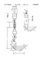
- FIG. 1is a block diagram of an embodiment of the invention with an embodiment of an external-cavity laser
- FIG. 2is an another embodiment of the external-cavity frequency-tunable laser shown in FIG. 1;
- FIG. 2ais another embodiment of the external-cavity frequency-tunable laser shown in FIG. 2 with the scanning mirror replaced by a AOTF unit;
- FIG. 3is an embodiment of a non-linear signal processing algorithm to compensate for non-linear frequency sweeps in the source
- FIG. 4is another embodiment of the invention using a tunable optical filter
- FIG. 5is yet another embodiment of the invention which is capable of producing images in multiple dimensions.
- FIG. 6is another embodiment of the invention in the form of a ring laser.
- an embodiment of an OCDR system 10includes an external-cavity frequency-tuned laser 14 which is rapidly and nearly continuously tunable, an interferometer 18, a processing unit 22 and a computer controller and display 26.
- light from the external-cavity frequency-tuned laser 14is divided by an optical coupler 30 into two beams. One beam is directed toward a reference mirror 34 and reflected back toward the coupler 30. The second beam is directed toward a sample 38. This light from coupler 30 impinges on the sample 38 by way of translatable probe 42. This probe 42 attached to a transverse scanning device 46 scans the beam across the sample 38.
- Transverse scanningmay be accomplished by a number of means including, but not limited to, moving mirrors, moving lenses, electrooptic deflector, or any other means to accomplish the translation of light across sample 38.
- the probe 42is stationary and the sample 38 is moved across the beam.
- Light reflected by the sample 38returns to the coupler 30 and combines with light reflected from the reference mirror 34.
- the recombined beamsform an interference pattern which is detected by photodetector 50.
- a signal generated by the photodetector 50is digitized and processed by the signal processor 22 and the result displayed on a computer controller and display 54.
- An embodiment of the external-cavity frequency-tunable laser shown in FIG. 1uses a broadbandwidth semiconductor 58 amplifier.
- the ends of the amplifier chip through which the optical beam propagatesare facets 59, 60 along the natural crystallographic cleavage planes of the chip. As such, they are parallel to each other.
- facets 59, 60along the natural crystallographic cleavage planes of the chip. As such, they are parallel to each other.
- Optical gainis provided by injecting current into the narrow stripe region defining the single spatial mode.
- some small reflectanceis required to provide oscillation in an external-cavity mode.
- the residual reflectance of the angled stripemay suffice if the external coating is appropriate, but it is preferable to have the stripe perpendicular to the output facet.
- an external-cavity laserhas portions of the cavity on both sides of the amplifier chip (double-ended external-cavity). In this case both amplifier facet reflectances, one at each end of the chip, must be suppressed.
- a semiconductor laseris shown in this embodiment, other embodiments utilize other optical gain media such as rare-earth doped fibers and other solid state gain media.
- a light beam exiting from the back facet 60is collimated by lens 62 and reflected from a steerable mirror 66.
- Embodiments of the steerable mirror 66includes a galvanometer, a PZT, an electro-optic beam deflector, or a voice coil driven mirror. The reflected light beam is directed to a wavelength selective element 70.
- the wavelength selective elementis a ruled grating.
- the ruled diffraction gratingoperates in the Littrow configuration, known in the art, which retro-reflects light of a wavelength obeying the diffraction condition determined by the angle of incidence and the grating ruling pitch.
- a dispersive prism followed by a mirroris used.
- An external-cavity for laser 14is formed between the partially reflective surface of the cleaved front facet surface 59 (or alternatively a partially transmissive surface in front of the laser) and the grating 70.
- the steerable mirror 66By angularly steering (arrow R) the steerable mirror 66, the laser 14 is frequency-tuned.
- the relative distance of the laser 58 to mirror 66 spacing, the laser 58 to grating 70 spacing, the grating angle ⁇ , and the grating rulingare properly selected nearly continuous frequency tuning can be accomplished.
- a conditionexists under which the frequency of a lasing axial cavity mode tunes at approximately the same rate as the grating center frequency thereby avoiding axial mode hop.
- Vis the distance from mirror 66 to grating 70
- L fis the fixed distance from the rotational axis of mirror 66 to laser front facet reflector 59
- ( ⁇ >45°)is the angle of incidence onto the grating at the scan center wavelength measured from a normal to its surface.
- This design criterionneglects dispersive effects, and provides first-order compensation for the axial mode tuning. Under the above spacing condition, there is a parabolic increase in the mode index about the center wavelength.
- a simple way to approximately compensate for this (and other dispersive effects)is to use a chirped Bragg grating in an optical fiber or optical planar waveguide to provide a quadratic phase shift to its reflected light. The compensation may be exact if a constant second derivative of phase with respect to frequency is used. However, this is a more stringent condition that requires carefully designing a chirped grating. It should be noted that with proper choice of grating length and chirp, nearly perfect mode compensation can be achieved over several percent of optical bandwidth without the stringent grating requirements just discussed.
- FIG. 2One embodiment of such external-cavity frequency-tuned laser using a chirped Bragg grating is shown in FIG. 2. Note that this embodiment is an example of a double-sided external-cavity, with optical elements on either side of the optical gain medium.
- a Bragg waveguide grating 80is used as a weak dispersive reflector to reflect light back into the external-cavity.
- the Bragg waveguide grating 80is also used as a transmissive output coupler.
- the rapid scanning Littrow steerable mirror 66 configuration of the previous embodimentis still used for linear frequency compensation, with a slight adjustment of the grating spacings to allow for a fixed component of cavity distance equal to one half the grating optical path length. That is: ##EQU2##
- a mode-hop, or change in mode orderis equivalent to having a different number of wavelengths in the cavity. If the wavelength increases at the same rate as the total cavity length increases, mode hops are not present.
- both the wavelength and the cavity lengthchange with tuning angle of mirror 66.
- the previous equationdefined a condition at which both the cavity length and retro-reflected wavelength tune with the same linear rate at the center of the tuning range.
- This tuninghas non-linear, primarily quadratic, components that cause the cavity length and wavelength changes to diverge on either side of the center of the tuning range. This divergence is referred to as a second-order deviation to the continuous tuning condition.
- the second-order correction conditionwhich if satisfied greatly extends the length range of non-mode hopping, is defined by: ##EQU3## where n is the average refractive index of the chirped Bragg grating, ⁇ 0 is the center optical frequency (and the Bragg frequency at the center of the grating), ⁇ r - ⁇ l is the chirp of the Bragg frequency across the grating (greater than or equal to the desired frequency sweep), and L g is the Bragg grating length.
- the distances V and L.sub. ⁇are experimentally adjusted near their nominal values for exact second and first order compensation, respectively.
- the fixed length L f in this embodimentis the fixed optical path length of the cavity that does not change with tuning conditions, extending from the center of the tuning mirror, through the collimating lenses and amplifier, to the interior side of the Bragg grating.
- an AOTFis used to replace the mechanically-scanned tuning mirror 66 of the embodiment of the external-cavity frequency-tunable laser shown in FIG. 2.
- the scanning mirror 66is replaced by a fixed diffraction grating 69.
- the AOTF 71is inserted in the collimated beam between the lens 62 and grating 69.
- the AOTF 71which is designed to impart no angular deviation to the beam as the AOTF is tuned, the diffraction angle from the grating 69 changes.
- the changing diffraction anglecauses a path length change in the beam retroreflected from the second Littrow grating 70 similar to that of the scanned mirror embodiment.
- the AOTFimparts a small optical frequency shift to the beam transmitted in one direction, but the frequency shift is reversed in the opposite direction, so that a beam propagating through a round trip in the cavity suffers no cumulative radio-frequency shifts.
- the output of the laseris sent into a Faraday isolator 84 and coupled into a fiber optic Michelson interferometer 18.
- the interferometeris constructed with angled fiber facets (not shown).
- the isolator 84 and angled fiber facetsserve to minimize reflections which can detrimentally effect the laser stability.
- One arm 88 of the interferometerleads to the reference mirror 34, the other to the probe module 47 that couples light to and from the sample 38 and performs transverse scanning 46.
- the probe module 47is scanned, alternatively in another embodiment the sample 38 is scanned laterally by translating the sample 38 perpendicular to the axis of the probe module 42 using linear translation stages or angular scanning devices as is known in the art.
- the light reflected from the reference mirror 34 and the sample 38are recombined by the beam splitter 30 and passed to the photodetector 50.
- a single photodetectoris shown, in another embodiment, double balanced detection is used as is known in the art, to cancel excess intensity noise from the source and sample-sample beat signals.
- the interformeteris modified from simple Michaelson interformeter as is known in the art.
- the signal generated by the photodetector 50 in response to the combined reflected lightis amplified, filtered and converted to a digital signal by an A/D converter and digitally processed by processor 22.
- analog signal processing techniquescould be used as is known in the art.
- the system 10When the angle (R) of the steerable mirror 60 is scanned in a saw-tooth pattern, the system 10 operates as a normal OFDR system with the added improvement of a nearly continuous frequency sweep as described in detail above.
- One embodiment of the device of FIG. 2(without the chirped Bragg grating) operated with a greater than 20 nm tuning range at 840 nm center frequency. Because the grating frequency does not vary linearly with mirror angle (R) (its wavelength tunes in a slightly non-linear manner with respect to incident angle), there is a slight frequency sweep non-linearity of the output spectrum that leads to decreased resolution. That is, the output frequency is not exactly linear in time and thus the beat frequencies between the reference reflector and a reflection from the sample will not be constant in time. The effects of such a non-linearity can be eliminated with post detection processing as described below or by altering (pre-distorting) the form of the scan from a saw tooth pattern.
- Normal and mechanically-resonant galvanometerscan be driven at video rates ( ⁇ 15 kHz) using a pure sinusoid.
- combinations of scanning mechanisms and frequency dispersive elementsare used to achieve very high rate tunable optical filters with a sinusoidal sweep pattern.
- rotating polygons, electro-optic beam deflectors, and tunable fiber Fabry Perot filtersmay be used with frequency dispersive elements to achieve high scanning rates, instead of the galvanometer and grating described above.
- the steerable mirroris a resonant galvanometer driven by a sinusoidal waveform, high speed -sinusoidal tuning of the laser frequency can be achieved.
- an auxiliary interferometer 96 in one embodimentis used to sample the signal produced by the photo-detector 50 at equal increments of the source frequency, as is known in the art.
- the auxiliary interferometer 96corrects for any non-linearity in frequency sweep by sampling the detected signal at equally spaced source frequency increments as is well known in the art.
- a separate calibration photodetectoris incorporated to measure the laser output power and used to adjust power of laser 14 or used to normalize the digitized signal in processing unit 22.
- the approach of using an auxiliary interferometer 96can partially correct for deviations from the ideal in the sweep of the optical source by providing signal trigger pulses at equally spaced increments in the source frequency, such approaches have several limitations, including hardware complexity and system performance limitations due to instabilities in the auxiliary interferometer 96 paths and processing electronics.
- correction for deviations from the ideal in the sweep of the optical sourceis performed by the signal processing of the detector signal.
- FIG. 3a flow diagram of an embodiment of a simplified version of the signal processing algorithm is shown.
- a portion of the periodic signal waveform generated by the detector 50is sampled over a monotonically increasing or decreasing period T at equally spaced time intervals using a precision clock (STEP 100).
- Non-uniform time samplescould also be used.
- the time axisis transformed to yield a beat signal characteristic of a linear frequency sweep with a transferred time axis (STEP 120).
- the new time axisis derived, several methods exist to process the data.
- the new time samplesare interpolated, with equal time increments in the new time axis coordinates, based on a linear or non-linear fit to the actual data values in the new time axis (STEP 130).
- standard Fourier analysis techniquessuch as the Fast Fourier Transform (FFT) are performed to obtain the reflectivity profile (STEP 140).
- FFTFast Fourier Transform
- Other algorithms to obtain the reflectivity profilesuch as maximum entropy and wavelet transforms, can also be used.
- A(t)is the amplitude of the electric field
- ⁇ ois the nominal center optical frequency
- tis time
- ⁇ (t)is the phase of the electric field.
- ⁇ (t)which describes the modulation of the optical carrier phase and frequency, includes a stochastic random phase component which is neglected for the purposes of this description.
- the detected photocurrentis proportional to the squared sum of the electric field reflected from the reference reflector 34, E r (t), and the reflected field from the sample 38, E s (t- ⁇ ), as given by the expression:
- ⁇is the relative delay between the reference reflection and the sample reflection and ⁇ is proportional to the relative distance into the sample 38.
- the signal component of interestwill consist of the cross term E r (t)•E s (t- ⁇ ).
- Other termsgive rise to DC components and signal-signal beat terms which can be removed by signal processing techniques as known in the art or by carefully selecting a nominal time delay between the sample and the reference so that the cross product of the signal and the signal beat noise does not spectrally interfere with the cross product of the reference and the signal spectrum.
- E r (t)is just a delayed and scaled version of E o (t) while, for a single reflection within the sample, E s (t- ⁇ ) is the product of a scaled and delayed version of E o (t) times the sample reflection coefficient r o Exp(j ⁇ r ), where r o and ⁇ r are the magnitude and phase of the reflection at ⁇ , respectively.
- r o and ⁇ rare the magnitude and phase of the reflection at ⁇ , respectively.
- f(t)is the modulated optical frequency about the optical carrier center frequency
- f o⁇ o /2 ⁇
- s(t)can be further simplified when f(x) is approximately constant over ⁇ , which is accurate for most of the applications of interest, to:
- Equation 11is functionally similar to equation 8 and thus standard Fourier analysis can be performed to derive r o and ⁇ . Since the time samples in equation 11 are not equally spaced, interpolated values of time and s(t) will generally have to be calculated before standard FFT algorithms can be applied. However other algorithms such as maximum entropy and wavelet transforms can be used for spectral estimation.
- the frequency sweep, f(t)will be periodic and can be broken up into monotonically increasing or decreasing segments where one-to-one mappings between frequency and time exist.
- f(t)changes from an increasing to a decreasing segment (or vise versa) it may be necessary to perform a windowing function to remove data which may not be of high fidelity during transitions.
- each segmentwill contain information about one axial reflectivity profile.
- Knowledge of the shape of the frequency sweep required by this embodiment of the algorithmic approachcan be obtained from the laser input if the behavior of the laser is well known. For example in a semiconductor laser where the frequency modulation response to current injection is known, then the laser frequency output is derivable from its input. In situations where the behavior is more complicated then optical calibration techniques can be used. For example one can use a calibrated narrowband optical filter (calibrated using a wavemeter for example) and time gating techniques to measure the relative time when the OFDR source frequency passes through the filter. By stepping the filter sequentially through the range of f(t), f(t) can be mapped out. Similarly one can use a laser of known frequency (using again a wavemeter) and perform gating using heterodyne techniques. Also various types of optical delay-lines and optical frequency discriminators (e.g. etalons, Fabry Perots, unbalanced Mach-Zehnder and Michelson interferometers) can be used to determine f(t).
- the OFDR systemitself can be used for calibration. If the sample is replaced with a simple and known reflection profile (e.g. a partially reflecting mirror) then with appropriate signal power normalization, the modulated frequency f(t) is contained in s(t) from, for example, equation 6. Using known curve fitting algorithms, f(t) can be derived since most of the parameters either are known (e.g. ⁇ o , ⁇ , ⁇ r , T o ) or can be derived by other means.
- a simple and known reflection profilee.g. a partially reflecting mirror
- f(t)can be derived since most of the parameters either are known (e.g. ⁇ o , ⁇ , ⁇ r , T o ) or can be derived by other means.
- f(t)is calibrated in real-time. Since calibration of f(t) can be determined in the manner described (or other techniques as is known in the art) then by placing a reference reflector (not shown) in the sample arm 88 one can perform calibration on a scan-to-scan basis increasing the accuracy of the reflectometry or imaging system. In such an embodiment it is important that the location of the reference reflector be such that the beat frequencies do not lie in a region that contains signals or otherwise interfere with the signal data collection.
- An alternative to placing the reference reflector in the sample armis to have the transverse scanning mechanism 46 point to a reference reflector periodically.
- an alternate embodiment of the systemuses an acousto-optic tunable filter 200 (AOTF) as a frequency tuning element.
- the AOTF 200has the desirable property that it has no moving parts.
- An AOTF configured in a double pass geometrycan produce an output frequency equal to the input frequency, a necessary condition for single-frequency operation.
- the poorer frequency resolution of an AOTF, plus the uncompensated nature of the cavity shown in FIG. 4would lead to mode hopping.
- a pair of gratings in a pulse compression/dispersion compensation geometry inserted in the cavityprovides a large degree of increased cavity mode separation and mode hop suppression.
- the embodiment shownincludes an alternate embodiment of the interferometer 18 utilizing a Faraday circulator 204.
- the laser source 141is coupled into a first port 208 of a Faraday circulator 204.
- Lightis passed from a second port of the Faraday circulator 212 where it is directed to a probe module 42.
- the probe module 42couples light to and from the sample 38 of interest and performs lateral scanning (Arrow L).
- the probe module 42in this embodiment, includes a reference reflection reflector 44.
- the reference reflector 44is a partially transmissive beam splitter (e.g. 10%).
- the reference reflectoris flat cleaved output end 45 of fiber 212.
- Reflected light from the reference and sample 38are coupled back to the Faraday circulator 204 and directed to the third port 216 of the Faraday circulator 204 where the light is guided to the photodetector 50 and the output signal processed by the processing unit 22.
- the magnitude of the reference reflectionis made as small as possible but sufficient to achieved shot-noise limited operation in the receiver as is known in the art. Ideally, this interferometeric approach can be more than 3 dB more efficient than the approach shown in FIG. 1 since no signal power is lost by being transmitted back toward the source by the coupler 30. Further, the reference reflection magnitude can be tailored to be as small as is practical.
- the Faraday circulator 204also helps to further isolate the laser source 141 from stray reflections.
- each reflectivity profileis interlaced with transverse scanning to produce a 2 or 3 dimensional image.
- direct acquisition of multiple longitudinal reflectivity profilescan be collected using an array detector as shown in the embodiment depicted in FIG. 5.
- the reference mirror 34may have any surface shape, from a simple planar mirror or a more complex 3-dimensional shape matched to the curvature of the sample 38 to optimize the data collection.
- the detector array 50is a one-or two-dimensional array. A one-dimensional embodiment of the array 50 can facilitate the capture of two-dimensional images.
- the imaging optics 248 in such an embodimentwould image a line in the sample 38 using anamorphic optics or cylindrical optics with appropriate lateral resolution and depth-of-field. The height of the line is selected for the application of interest.
- the imaging optics 248 in the detector arm 250magnify or demagnify the source image to map into the particular detector geometry.
- a two-dimensional embodiment of the arraypermits three-dimensional images to be acquired and the optics in such an embodiment map a transverse area of the sample into the transverse area of the detector 50.
- the imaging opticsalso map out the appropriate depth-of-field in the sample.
- the longitudinal (or depth into the sample) distance that the OFDR system images overwill be determined in part by the depth of field or confocal parameter of the imaging optics used to image into the sample.
- appropriate area detectorsinclude line and area CCD's (preferably with frame store areas for faster and more sensitive acquisition), PIN photodetector arrays, and CID detectors.
- FIG. 6shows another embodiment of a tunable laser source as a ring laser that can be used to perform reflectometry and imaging measurements.
- a fiber ringis shown, although free space embodiments are also possible.
- the fiber ringincludes an optical gain medium (300).
- the optical gain medium 300is a semiconductor with angled or appropriately antireflection coated facets to suppress lasing.
- the gain medium 300is a rare-earth doped fiber because it is small and readily compatible with fiber ring implementations.
- the fiberis doped with a dopant such as Yb, Er, Nd, and Tm or a Raman gain medium.
- Other embodimentsinclude solid state gain media.
- long-period fiber gratingsare spliced into the fiber ring so that the optical gain over the laser sweep range is relatively flat and broad.
- a faraday isolator 305is inserted in the ring to insure unidirectional operation and a faraday isolator 304 is installed at the output 308 to eliminate any feedback into the laser cavity.
- the ringmay be manufactured out of polarization maintaining fiber, single-polarization fiber, or contain fixed or adjustable polarization components.
- Every embodiment of the ring laserincludes a tunable optical filter 312.
- this filtermay be a fiber Fabry-Perot Filter, acousto-optic tunable filter (AOTF), or tunable mirror/grating as described previously.
- the tunable filtermay be driven in a saw-tooth or triangular fashion (if sufficient tuning bandwidth is available) or a sinusoidal or other drive fashion (if compensated for as described previously).
- a path length compensation element 316such as a Fiber Bragg reflector and Faraday circulator or other dispersive or path length compensating element, is included in the ring. As the tunable filter is tuned, this path length compensator 316, which includes an active or passive element, adjusts the total ring optical path length to maintain the lasing condition at the peak of the tunable filter 312.
- the path length compensator 316includes a free space coupling region over which the air gap is adjusted during the filter tuning.
- a frequency shifter 320such as an acousto-optic modulator (AOM), or serrodyne phase modulator (SPM) is inserted into the laser cavity.
- AOMacousto-optic modulator
- SPMserrodyne phase modulator
- the output frequency and throughput (loss) of the lightcan be controlled by the frequency and intensity of the radiofrequency drive 324 for the AOM.
- the optical filter 312is tuned at a rate that equals the frequency shift of the frequency shift element 320 divided by the round-trip propagation delay of the light around the ring then a narrow linewidth frequency sweep will be achieved.
- f 0 'is the rate (the prime (') indicating a derivative with respect to time) of tuning of the laser optical frequency
- f f 'is the tuning rate of the optical filter 312
- cis the speed of light
- f Braggis the frequency shift of frequency shifting element 320
- n g ( ⁇ )is the effective group index of refraction
- ⁇is the instantaneous optical wavelength
- Lis the cavity length
- the output frequencyis precisely incremented by an amount equal to the frequency shift imposed by the frequency shifter 320 every time the light circles around the ring.
- the filter center frequency tuning rateis equal to the frequency shift divided by the round trip propagation time. For example, if the AOM with a Bragg frequency shift of 600 MHz is used as a frequency shifting element 320; a fiber Fabry Perot filter is used as a tunable filter 312; a semiconductor optical amplifier 300 with a bandwidth of 50 nm ( ⁇ 6.25 THz) and center frequency of 1500 nm is used as a gain element; then, assuming a cavity length of ⁇ 19.2 m and a group index of refraction of 1.5, the round trip propagation time is ⁇ 96 ns. Therefore a bandwidth of 50 nm can be tuned in ⁇ 1 ms for a repetition rate of ⁇ 1 kHz.
- a standard AOM operating as a frequency shifter 320has a limited optical bandwidth for a fixed input and output angle.
- electro-optical modulatorsIn addition at the expense of additional hardware complexity, autonomous alignment techniques can be implemented and the AOM can be made to work over a broad bandwidth.
- an AOTFis used in place of the tunable filter 312, and the frequency shifter 320, combining their functions into one element.
- the AOTFhas the disadvantage that tuning the AOTF center wavelength requires that the AOTF radio frequency shift be changed leading to complexities in satisfying the above resonance condition. This limitation can result in mode hops and unacceptable laser linewidth which leads to poor system dynamic range.
- the mode hopsresult from the fact that if the filter optical center frequency is swept linearly in time, then the Bragg frequency shift will not be constant as was the case with an AOM, but rather will vary with time. This leads to the inability of the optical filter center frequency to track the laser frequency, resulting in mode hopping.
- the path length compensation element 316(passive or active) adjusts the round trip propagation delay (thereby changing the effective n g ( ⁇ ) in the above expression) to compensate for the change in Bragg frequency shift. That is, if the Bragg frequency shift must be increased by 1% to tune the AOTF from one end of the optical spectrum to the other, the path length compensation element 316 must increase the round trip propagation time by 1% also. This is accomplished using a passive device such as a Bragg fiber grating and a circulator or by using an active optical delay line such as a fiber stretcher or adjustable free space optical path element.
- the integrandcan be expressed as a quadratic function of frequency: ##EQU5## This results in the following equation to be solved for ⁇ (t): ##EQU6## From this expression, the corresponding time-dependent radio-frequency drive of the AOTF can be found.
- one embodimentcompensates for the non-linear frequency sweep with an auxiliary interferometer or with the signal processing algorithm described previously.
- a power calibration element 328is used to maintain a known intensity profile of the output waveform (e.g. uniform or raised-cosine).
- a coupler 332is used to remove a portion of the output light onto a photodetector which is included in the power calibration element 328. The output of this photodetector is compared to a reference level and the difference 336 is used to adjust the gain 340 of the optical gain medium 300.
- the difference 336'is used to control the throughput loss of the frequency shifter 320 or optical filter 312.
- the powercan simply be monitored and used as an input to the post-detection signal processing unit as described previously.
- the Bragg frequency shift of an AOMis adjusted to keep the laser at its resonance condition when a tunable filter Fabry Perot filter, whose center frequency can not be linearly tuned, is used as the tunable optical filter.
- the filterconsists of a cascade of optical filters such as an AOTF and a Fabry Perot filter.
- the specimenfor example a biological organism
- the specimenmay contain moving objects, for example blood flow, under measurement.
- the OFDR imaging designs and methods described hereinallow the extraction of velocity, position, and magnitude of reflections on a high resolution scale ( ⁇ 10 ⁇ m).
- the detected signalwill be a constant frequency sinusoid the magnitude of which is proportional to the reflectivity of the target.
- the received signalconsists of a chirped frequency sinusoid whose average or nominal frequency will be Doppler upshifted or downshifted depending on the relative motion of the object with respect to measurement system and the rate of the source frequency sweep.
- the chirpthe actual location of the target along with its velocity is obtained.
- the instantaneous beat frequency, ⁇ bgenerated by the OFDR system is approximately given by the equation: ##EQU7## where ⁇ 0 is the known starting optical frequency, ⁇ 1 is the known optical frequency sweep rate from that frequency, z is the unknown target range (with respect to the fixed reference mirror), v is the unknown target velocity (normal to the incident light beam), and c is the speed of light.
- the first termis a constant frequency proportional to the distance to the target; the second term is proportional to the velocity of the target and is the Doppler component; and the final term is the chirp in the beat frequency which is proportional to the target velocity times the optical frequency sweep scan rate.
- the beat signalwill consist of the sum of differently weighted multiple beat frequency terms.
- the optical technique of the present inventionwith its large frequency sweep rate (orders of magnitude larger than in rf or typical optical radar) enables a unique means of extracting Doppler information from a single sweep.
- a target at a certain distanceproduces a beat frequency which is proportional to its distance. If the target is moving, a Doppler offset is added to this beat frequency, and this combined beat frequency is broadened (chirped) by the target motion.
- Neither the range or Doppler offsetare known a priori. Further, in many situations there may be multiple targets with different ranges and velocities.
- a method of extracting both range and velocity informationmultiplies the digitized received waveform by a series of dechirping functions having quadratic time-dependent phase factors of the form exp(-jKt 2 ), each differing by the proportionality constant K.
- Kis related to a different Doppler velocity and the known optical frequency scan rate.
- Each of the series of dechirped waveformsis then Fourier transformed using an FFT or other suitable algorithm.
- the corresponding Doppler offsetis subtracted in the frequency domain from the transformed signal to provide the portion of the beat frequency arising from range.
- Each targetproduces a peak signal from a different distinct point in the range-velocity plane.
- chirped pulsesare sequentially incident onto the target and Doppler information is extracted by processing the reflected light across the multiple pulses, in a manner similar to that of 10.6 ⁇ m long-range optical radar.
- range and Doppler informationmay be extracted using the information contained in a complete cycle of swept frequency, as is known in the art of FM-CW radar systems.
- the reference frequencyis greater than the delayed return frequency from the target (for relatively large ranges, and smaller Doppler shifts)
- the reference frequencyis less than the delayed return frequency from the target.
- the difference frequency of the interferometric beat signalis the same for both portions of the sweep.
- the targetis moving, its frequency is Doppler shifted, so that the difference frequency between the reference and delayed Doppler-shifted return frequency from the target will not be the same during two half sweeps.
- the mean of the (Doppler shifted) target return positionswill give the target position, and the difference between the mean and individual spectra will give the Doppler shift.
Landscapes
- Physics & Mathematics (AREA)
- Health & Medical Sciences (AREA)
- Life Sciences & Earth Sciences (AREA)
- General Physics & Mathematics (AREA)
- Engineering & Computer Science (AREA)
- General Health & Medical Sciences (AREA)
- Surgery (AREA)
- Optics & Photonics (AREA)
- Nuclear Medicine, Radiotherapy & Molecular Imaging (AREA)
- Biophysics (AREA)
- Medical Informatics (AREA)
- Animal Behavior & Ethology (AREA)
- Heart & Thoracic Surgery (AREA)
- Public Health (AREA)
- Veterinary Medicine (AREA)
- Biomedical Technology (AREA)
- Radiology & Medical Imaging (AREA)
- Molecular Biology (AREA)
- Pathology (AREA)
- Electromagnetism (AREA)
- Spectroscopy & Molecular Physics (AREA)
- Ophthalmology & Optometry (AREA)
- Automation & Control Theory (AREA)
- Condensed Matter Physics & Semiconductors (AREA)
- Chemical & Material Sciences (AREA)
- Analytical Chemistry (AREA)
- Biochemistry (AREA)
- Immunology (AREA)
- Plasma & Fusion (AREA)
- Length Measuring Devices By Optical Means (AREA)
- Investigating Or Analysing Materials By Optical Means (AREA)
- Lasers (AREA)
- Spectrometry And Color Measurement (AREA)
Abstract
Description
E.sub.o (t)=A(t)Exp(j(ω.sub.o t+φ(t))) (1)
I(t)˜|E.sub.r (t)+E.sub.s (t-τ)|.sup.2 (2)
s(t)=r.sub.o cos (ω.sub.o τ+φ.sub.r +φ(t)-φ(t-τ)) (3)
=r.sub.o cos (ω.sub.o τ+φ.sub.r +2π∫dxf(x))x={t-τ, t} (4)s(t)≈r.sub.o cos (ω.sub.o τ+φ.sub.r +2πf(t-τ/2)τ)) (5)
s(t)≈r.sub.o cos (ω.sub.o τ+φ.sub.r +2πf(t)τ) (6)
φ(t)=(Δf/T.sub.o)t (7)
s(t)=r.sub.o cos (ω.sub.o τ+φ.sub.r +2π(Δf/T.sub.o)τt) (8)
f(t)=(Δf/2) sin (ω.sub.m t) (9)
s(t)=r.sub.o cos (ω.sub.o τ+φ.sub.r +2π(Δf/2)τ sin (ω.sub.m t)) (10)
S(t.sub.new)=r.sub.o cos (ω.sub.o τ+φ.sub.r +2π(Δf/T.sub.m)τt.sub.new) (11)
t.sub.new =(T.sub.o /Δf)f(t) (12)
S(t.sub.new)=r.sub.o cos (ω.sub.o τ+φ.sub.r +2π(Δf/T.sub.o)τt.sub.new) (13)
ƒ.sub.0 '=ƒ.sub.ƒ '=cƒ.sub.Bragg |(n.sub.g (λ)L)
Claims (13)
Priority Applications (3)
| Application Number | Priority Date | Filing Date | Title |
|---|---|---|---|
| US08/877,340US5956355A (en) | 1991-04-29 | 1997-06-17 | Method and apparatus for performing optical measurements using a rapidly frequency-tuned laser |
| PCT/US1998/000071WO1998035203A2 (en) | 1997-02-07 | 1998-02-04 | Method and apparatus for performing optical measurements using a rapidly frequency-tuned laser |
| US09/330,804US6160826A (en) | 1991-04-29 | 1999-06-11 | Method and apparatus for performing optical frequency domain reflectometry |
Applications Claiming Priority (9)
| Application Number | Priority Date | Filing Date | Title |
|---|---|---|---|
| US69287791A | 1991-04-29 | 1991-04-29 | |
| US08/033,194US5459570A (en) | 1991-04-29 | 1993-03-16 | Method and apparatus for performing optical measurements |
| US25294094A | 1994-06-02 | 1994-06-02 | |
| US49273895A | 1995-06-21 | 1995-06-21 | |
| US08/577,366US5748598A (en) | 1995-12-22 | 1995-12-22 | Apparatus and methods for reading multilayer storage media using short coherence length sources |
| US08/607,787US6134003A (en) | 1991-04-29 | 1996-02-27 | Method and apparatus for performing optical measurements using a fiber optic imaging guidewire, catheter or endoscope |
| US3748897P | 1997-02-07 | 1997-02-07 | |
| US08/877,340US5956355A (en) | 1991-04-29 | 1997-06-17 | Method and apparatus for performing optical measurements using a rapidly frequency-tuned laser |
| US08/916,759US5784352A (en) | 1995-07-21 | 1997-08-19 | Apparatus and method for accessing data on multilayered optical media |
Related Parent Applications (1)
| Application Number | Title | Priority Date | Filing Date |
|---|---|---|---|
| US08/607,787Continuation-In-PartUS6134003A (en) | 1991-04-29 | 1996-02-27 | Method and apparatus for performing optical measurements using a fiber optic imaging guidewire, catheter or endoscope |
Related Child Applications (1)
| Application Number | Title | Priority Date | Filing Date |
|---|---|---|---|
| US09/330,804DivisionUS6160826A (en) | 1991-04-29 | 1999-06-11 | Method and apparatus for performing optical frequency domain reflectometry |
Publications (1)
| Publication Number | Publication Date |
|---|---|
| US5956355Atrue US5956355A (en) | 1999-09-21 |
Family
ID=26714173
Family Applications (2)
| Application Number | Title | Priority Date | Filing Date |
|---|---|---|---|
| US08/877,340Expired - LifetimeUS5956355A (en) | 1991-04-29 | 1997-06-17 | Method and apparatus for performing optical measurements using a rapidly frequency-tuned laser |
| US09/330,804Expired - Fee RelatedUS6160826A (en) | 1991-04-29 | 1999-06-11 | Method and apparatus for performing optical frequency domain reflectometry |
Family Applications After (1)
| Application Number | Title | Priority Date | Filing Date |
|---|---|---|---|
| US09/330,804Expired - Fee RelatedUS6160826A (en) | 1991-04-29 | 1999-06-11 | Method and apparatus for performing optical frequency domain reflectometry |
Country Status (2)
| Country | Link |
|---|---|
| US (2) | US5956355A (en) |
| WO (1) | WO1998035203A2 (en) |
Cited By (289)
| Publication number | Priority date | Publication date | Assignee | Title |
|---|---|---|---|---|
| US20020036775A1 (en)* | 2000-08-08 | 2002-03-28 | Carl Zeiss Jena Gmbh | Method for increasing the spectral and spatial resolution of detectors |
| US6399404B2 (en)* | 1998-09-28 | 2002-06-04 | Nec Corporation | Fabricating method of optical semiconductor device |
| US20020141714A1 (en)* | 2001-02-17 | 2002-10-03 | Reed William Alfred | Grin-fiber lens based optical endoscopes |
| US20020140942A1 (en)* | 2001-02-17 | 2002-10-03 | Fee Michale Sean | Acousto-optic monitoring and imaging in a depth sensitive manner |
| US20020176452A1 (en)* | 2001-03-16 | 2002-11-28 | Lin Hong Tony | Digital control of actively mode-locked lasers |
| US20020176134A1 (en)* | 2001-05-24 | 2002-11-28 | Optinel Systems, Inc. | Dynamically reconfigurable add/drop multiplexer with low coherent cross-talk for optical communication networks |
| US6490390B1 (en)* | 2001-01-05 | 2002-12-03 | Phaethon Communications | Grating writing systems based on an acousto-optic element |
| US20030016706A1 (en)* | 2001-05-03 | 2003-01-23 | Flint Graham W. | Tunable single frequency filter for lasers |
| US20030035163A1 (en)* | 2001-08-15 | 2003-02-20 | Althouse Bryan L. | Optical channel monitor utilizing multiple fabry-perot filter pass-bands |
| US20030045798A1 (en)* | 2001-09-04 | 2003-03-06 | Richard Hular | Multisensor probe for tissue identification |
| US20030107743A1 (en)* | 2001-12-06 | 2003-06-12 | Van Wiggeren Gregory D. | Phase noise compensation in an interferometric system |
| US6580517B2 (en)* | 2000-03-01 | 2003-06-17 | Lambda Physik Ag | Absolute wavelength calibration of lithography laser using multiple element or tandem see through hollow cathode lamp |
| US20030118305A1 (en)* | 2001-02-17 | 2003-06-26 | Reed William Alfred | Grin fiber lenses |
| US6590910B2 (en)* | 2000-09-22 | 2003-07-08 | Calmar Optcom, Inc. | Actively mode-locked fiber laser with controlled chirp output |
| US20030128924A1 (en)* | 2001-12-20 | 2003-07-10 | Optinel Systems, Inc. | Wavelength tunable filter device for fiber optic systems |
| US20030128359A1 (en)* | 2002-01-10 | 2003-07-10 | Yokogawa Electric Corporation | Spectrometer |
| US20030133477A1 (en)* | 2002-01-05 | 2003-07-17 | Jian Lin | Stable and high speed full range laser wavelength tuning with reduced group delay and temperature variation compensation |
| US6597458B2 (en) | 2001-02-02 | 2003-07-22 | Texas Christian University | Method and system for stabilizing and demodulating an interferometer at quadrature |
| US6619864B2 (en) | 2001-03-15 | 2003-09-16 | Optinel Systems, Inc. | Optical channel monitor with continuous gas cell calibration |
| US20030184760A1 (en)* | 2000-09-13 | 2003-10-02 | Gerhard Bonnet | Optical device |
| US20030184758A1 (en)* | 2000-09-04 | 2003-10-02 | Anders Bjarklev | Optical amplification in coherence reflectometry |
| US6633593B2 (en)* | 2001-01-02 | 2003-10-14 | Spectrasensors, Inc. | Tunable semiconductor laser having cavity with wavelength selective mirror and Mach-Zehnder interferometer |
| US6654127B2 (en)* | 2001-03-01 | 2003-11-25 | Carl Zeiss Ophthalmic Systems, Inc. | Optical delay line |
| US6657727B1 (en)* | 1998-09-11 | 2003-12-02 | Joseph A. Izatt | Interferometers for optical coherence domain reflectometry and optical coherence tomography using nonreciprocal optical elements |
| US6687014B2 (en) | 2002-01-16 | 2004-02-03 | Infineon Technologies Ag | Method for monitoring the rate of etching of a semiconductor |
| US20040028329A1 (en)* | 2001-02-17 | 2004-02-12 | Reed William Alfred | Fiber devices using GRIN fiber lenses |
| US20040032886A1 (en)* | 2002-08-09 | 2004-02-19 | California Institute Of Technology | Tunable semiconductor lasers |
| US20040062483A1 (en)* | 2002-06-28 | 2004-04-01 | Shervin Taghavi-Larigani | Optical resonator and laser applications |
| US6731423B1 (en)* | 2001-08-15 | 2004-05-04 | Neumann Information Systems Inc | Optical amplifier and method |
| US20040109487A1 (en)* | 2002-12-06 | 2004-06-10 | Zhang Guangzhi G. | External cavity laser with dispersion compensation for mode-hop-free tuning |
| US6778307B2 (en)* | 2001-02-21 | 2004-08-17 | Beyond 3, Inc. | Method and system for performing swept-wavelength measurements within an optical system |
| US20040165639A1 (en)* | 2002-11-05 | 2004-08-26 | Jds Uniphase Corporation, State Of Incorporation: Delaware | Laser device |
| US20040169854A1 (en)* | 2003-02-28 | 2004-09-02 | Tuan Vo-Dinh | Integrated tunable optical sensor (ITOS) system |
| US6845108B1 (en) | 2001-05-14 | 2005-01-18 | Calmar Optcom, Inc. | Tuning of laser wavelength in actively mode-locked lasers |
| US20050018200A1 (en)* | 2002-01-11 | 2005-01-27 | Guillermo Tearney J. | Apparatus for low coherence ranging |
| US20050030550A1 (en)* | 2003-08-08 | 2005-02-10 | Mitutoyo Corporation | Method and apparatus for self-calibration of a tunable-source phase shifting interferometer |
| US20050113678A1 (en)* | 2002-01-15 | 2005-05-26 | Villard Joseph W. | Methods and compositions to reduce scattering of light during therapeutic and diagnostic imaging procedures |
| US6900943B2 (en)* | 2000-10-31 | 2005-05-31 | Forskningscenter Riso | Optical amplification in coherent optical frequency modulated continuous wave reflectometry |
| US20050171438A1 (en)* | 2003-12-09 | 2005-08-04 | Zhongping Chen | High speed spectral domain functional optical coherence tomography and optical doppler tomography for in vivo blood flow dynamics and tissue structure |
| US6950692B2 (en) | 1998-03-06 | 2005-09-27 | Imalux Corporation | Optical coherence tomography apparatus, optical fiber lateral scanner and a method for studying biological tissues in vivo |
| US20050254059A1 (en)* | 2004-05-14 | 2005-11-17 | Alphonse Gerard A | Low coherence interferometric system for optical metrology |
| US20050254060A1 (en)* | 2004-05-14 | 2005-11-17 | Alphonse Gerard A | Low coherence interferometry for detecting and characterizing plaques |
| US20050254061A1 (en)* | 2004-05-14 | 2005-11-17 | Alphonse Gerard A | Low coherence interferometry for detecting and characterizing plaques |
| US20050280828A1 (en)* | 2001-10-16 | 2005-12-22 | The General Hospital Corporation | Systems and methods for imaging a sample |
| US20060095065A1 (en)* | 2004-09-24 | 2006-05-04 | Tetsuaki Tanimura | Fluid occluding devices and methods |
| US20060103850A1 (en)* | 2004-11-12 | 2006-05-18 | Alphonse Gerard A | Single trace multi-channel low coherence interferometric sensor |
| US20060109477A1 (en)* | 2004-11-19 | 2006-05-25 | Yan Zhou | High efficiency balanced detection interferometer |
| US20060114473A1 (en)* | 2004-11-29 | 2006-06-01 | The General Hospital Corporation | Arrangements, devices, endoscopes, catheters and methods for performing optical imaging by simultaneously illuminating and detecting multiple points on a sample |
| US20060171503A1 (en)* | 2005-01-21 | 2006-08-03 | O'hara Keith E | Method to suppress artifacts in frequency-domain optical coherence tomography |
| US20060170919A1 (en)* | 2005-01-28 | 2006-08-03 | Anritsu Corporation | Optical spectrum analyzer |
| US20060187537A1 (en)* | 2005-01-20 | 2006-08-24 | Robert Huber | Mode locking methods and apparatus |
| US20060203859A1 (en)* | 2005-01-24 | 2006-09-14 | Cable Alex E | Compact multimode laser with rapid wavelength scanning |
| US20060241503A1 (en)* | 2005-02-10 | 2006-10-26 | Lightlab Imaging, Inc. | Optical coherence tomography apparatus and methods |
| US20070002327A1 (en)* | 2005-07-01 | 2007-01-04 | Yan Zhou | Fourier domain optical coherence tomography employing a swept multi-wavelength laser and a multi-channel receiver |
| US20070008545A1 (en)* | 2005-07-08 | 2007-01-11 | Feldchtein Felix I | Common path frequency domain optical coherence reflectometer and common path frequency domain optical coherence tomography device |
| US7184148B2 (en) | 2004-05-14 | 2007-02-27 | Medeikon Corporation | Low coherence interferometry utilizing phase |
| US20070051882A1 (en)* | 2005-09-08 | 2007-03-08 | Brooks Childers | System and method for monitoring a well |
| US20070055117A1 (en)* | 2004-05-14 | 2007-03-08 | Alphonse Gerard A | Low coherence interferometry utilizing phase |
| US7231243B2 (en) | 2000-10-30 | 2007-06-12 | The General Hospital Corporation | Optical methods for tissue analysis |
| JP2007178169A (en)* | 2005-12-27 | 2007-07-12 | Fujifilm Corp | Optical tomographic imaging system |
| US20070237194A1 (en)* | 2006-04-05 | 2007-10-11 | Ciena Corporation | Systems and methods for real-time compensation for non-linearity in optical sources for analog signal transmission |
| US20070260198A1 (en)* | 2003-04-25 | 2007-11-08 | Lightlab Imaging, Llc | Flush catheter with flow directing sheath |
| US20070279636A1 (en)* | 2004-08-27 | 2007-12-06 | Qun Li | All-fiber spectroscopic optical sensor |
| US20070278389A1 (en)* | 2006-06-02 | 2007-12-06 | Mahesh Ajgaonkar | Multi-channel low coherence interferometer |
| US20080021276A1 (en)* | 2006-07-21 | 2008-01-24 | Oncoscope, Inc. | Protective probe tip, particularly for use on a fiber-optic probe used in an endoscopic application |
| US7327463B2 (en) | 2004-05-14 | 2008-02-05 | Medrikon Corporation | Low coherence interferometry utilizing magnitude |
| US20080055579A1 (en)* | 2006-09-05 | 2008-03-06 | Joshua Monroe Cobb | Optical power modulation at high frequency |
| US7355716B2 (en) | 2002-01-24 | 2008-04-08 | The General Hospital Corporation | Apparatus and method for ranging and noise reduction of low coherence interferometry LCI and optical coherence tomography OCT signals by parallel detection of spectral bands |
| US7359057B2 (en) | 2005-08-26 | 2008-04-15 | Ball Aerospace & Technologies Corp. | Method and apparatus for measuring small shifts in optical wavelengths |
| US20080097225A1 (en)* | 2006-10-19 | 2008-04-24 | The General Hospital Corporation | Apparatus and method for obtaining and providing imaging information associated with at least one portion of a sample, and effecting such portion(s) |
| US7365859B2 (en) | 2004-09-10 | 2008-04-29 | The General Hospital Corporation | System and method for optical coherence imaging |
| US7366376B2 (en) | 2004-09-29 | 2008-04-29 | The General Hospital Corporation | System and method for optical coherence imaging |
| US20080117430A1 (en)* | 2006-11-17 | 2008-05-22 | Fujifilm Corporation | Method, apparatus, and program for processing tomographic images, and optical tomography system |
| US7382949B2 (en) | 2004-11-02 | 2008-06-03 | The General Hospital Corporation | Fiber-optic rotational device, optical system and method for imaging a sample |
| US20080140341A1 (en)* | 2006-07-10 | 2008-06-12 | The Board Of Trustees Of The University Of Illinois | Interferometric Synthetic Aperture Microscopy |
| US20080161696A1 (en)* | 2006-11-08 | 2008-07-03 | Lightlab Imaging, Inc. | Opto-acoustic imaging devices and methods |
| US20080165366A1 (en)* | 2007-01-10 | 2008-07-10 | Lightlab Imaging, Inc. | Methods and apparatus for swept-source optical coherence tomography |
| US20080195336A1 (en)* | 2004-10-08 | 2008-08-14 | Trajan Badju | Method and a System For Generating Three- or Two-Dimensional Images |
| US7418169B2 (en) | 2006-02-01 | 2008-08-26 | The General Hospital Corporation | Apparatus for controlling at least one of at least two sections of at least one fiber |
| US7447408B2 (en) | 2004-07-02 | 2008-11-04 | The General Hospital Corproation | Imaging system and related techniques |
| JP2008275528A (en)* | 2007-05-02 | 2008-11-13 | Fujifilm Corp | Compensation table generation method, apparatus, program, and tomographic image processing apparatus using the same |
| EP2008579A2 (en) | 2003-06-06 | 2008-12-31 | The General Hospital Corporation | Process and apparatus for a wavelength tuned light source |
| US20090073454A1 (en)* | 2007-09-19 | 2009-03-19 | Fujifilm Corporation | Optical tomography imaging system, contact area detecting method and image processing method using the same, and optical tomographic image obtaining method |
| US20090073456A1 (en)* | 2007-09-13 | 2009-03-19 | Duke University | Apparatuses, systems, and methods for low-coherence interferometry (lci) |
| US20090103792A1 (en)* | 2007-10-22 | 2009-04-23 | Visiongate, Inc. | Depth of Field Extension for Optical Tomography |
| US20090122320A1 (en)* | 2007-11-12 | 2009-05-14 | Lightlab Imaging, Inc. | Imaging catheter with integrated reference reflector |
| US7538859B2 (en) | 2006-02-01 | 2009-05-26 | The General Hospital Corporation | Methods and systems for monitoring and obtaining information of at least one portion of a sample using conformal laser therapy procedures, and providing electromagnetic radiation thereto |
| US7551293B2 (en) | 2003-11-28 | 2009-06-23 | The General Hospital Corporation | Method and apparatus for three-dimensional spectrally encoded imaging |
| US20090168071A1 (en)* | 2007-12-27 | 2009-07-02 | Fujifilm Corporation | Method and system for producing tomographic image by optical tomography |
| US20090177094A1 (en)* | 2008-01-08 | 2009-07-09 | Oncoscope, Inc. | Systems and methods for tissue examination, diagnostic, treatment, and/or monitoring |
| US20090174931A1 (en)* | 2005-01-20 | 2009-07-09 | Huber Robert A | Fourier domain mode locking: method and apparatus for control and improved performance |
| US7567349B2 (en) | 2003-03-31 | 2009-07-28 | The General Hospital Corporation | Speckle reduction in optical coherence tomography by path length encoded angular compounding |
| US20090198125A1 (en)* | 2008-02-01 | 2009-08-06 | Fujifilm Corporation | Oct optical probe and optical tomography imaging apparatus |
| US20090213387A1 (en)* | 2008-02-25 | 2009-08-27 | Fujifilm Corporation | Optical probe and optical tomographic image production apparatus using the probe |
| US20090290167A1 (en)* | 2008-05-15 | 2009-11-26 | Axsun Technologies, Inc. | Optical Coherence Tomography Laser with Integrated Clock |
| US20090306520A1 (en)* | 2008-06-02 | 2009-12-10 | Lightlab Imaging, Inc. | Quantitative methods for obtaining tissue characteristics from optical coherence tomography images |
| US7643153B2 (en)* | 2003-01-24 | 2010-01-05 | The General Hospital Corporation | Apparatus and method for ranging and noise reduction of low coherence interferometry LCI and optical coherence tomography OCT signals by parallel detection of spectral bands |
| WO2010006785A1 (en)* | 2008-07-16 | 2010-01-21 | Carl Zeiss Surgical Gmbh | Optical coherence tomography methods and systems |
| US20100014090A1 (en)* | 2005-10-11 | 2010-01-21 | Duke University | Systems and methods for endoscopic angle-resolved low coherence interferometry |
| US20100027025A1 (en)* | 2008-08-01 | 2010-02-04 | Koki Nakabayashi | Optical probe and optical tomographic imaging apparatus |
| US20100094127A1 (en)* | 2008-10-14 | 2010-04-15 | Lightlab Imaging, Inc. | Methods for stent strut detection and related measurement and display using optical coherence tomography |
| US7733497B2 (en) | 2003-10-27 | 2010-06-08 | The General Hospital Corporation | Method and apparatus for performing optical imaging using frequency-domain interferometry |
| US7742173B2 (en) | 2006-04-05 | 2010-06-22 | The General Hospital Corporation | Methods, arrangements and systems for polarization-sensitive optical frequency domain imaging of a sample |
| US7761139B2 (en) | 2003-01-24 | 2010-07-20 | The General Hospital Corporation | System and method for identifying tissue using low-coherence interferometry |
| US7782464B2 (en) | 2006-05-12 | 2010-08-24 | The General Hospital Corporation | Processes, arrangements and systems for providing a fiber layer thickness map based on optical coherence tomography images |
| US7796270B2 (en) | 2006-01-10 | 2010-09-14 | The General Hospital Corporation | Systems and methods for generating data based on one or more spectrally-encoded endoscopy techniques |
| US20100253949A1 (en)* | 2007-11-12 | 2010-10-07 | Lightlab Imaging, Inc. | Miniature Optical Elements for Fiber-Optic Beam Shaping |
| US20100259760A1 (en)* | 2007-10-04 | 2010-10-14 | Attocube Systems Ag | Device for position detection |
| US7843572B2 (en) | 2005-09-29 | 2010-11-30 | The General Hospital Corporation | Method and apparatus for optical imaging via spectral encoding |
| US7859679B2 (en)* | 2005-05-31 | 2010-12-28 | The General Hospital Corporation | System, method and arrangement which can use spectral encoding heterodyne interferometry techniques for imaging |
| US20100332174A1 (en)* | 2003-08-01 | 2010-12-30 | Ge Healthcare Bio-Sciences Ab | Method and apparatus for quantitating surface-binding optical resonance profiles |
| US7865231B2 (en) | 2001-05-01 | 2011-01-04 | The General Hospital Corporation | Method and apparatus for determination of atherosclerotic plaque type by measurement of tissue optical properties |
| US7884945B2 (en) | 2005-01-21 | 2011-02-08 | Massachusetts Institute Of Technology | Methods and apparatus for optical coherence tomography scanning |
| US7889348B2 (en) | 2005-10-14 | 2011-02-15 | The General Hospital Corporation | Arrangements and methods for facilitating photoluminescence imaging |
| US20110051148A1 (en)* | 2009-09-03 | 2011-03-03 | Axsun Technologies, Inc. | Filtered ASE Swept Source for OCT Medical Imaging |
| US20110051143A1 (en)* | 2009-09-03 | 2011-03-03 | Axsun Technologies, Inc. | ASE Swept Source with Self-Tracking Filter for OCT Medical Imaging |
| US7911621B2 (en) | 2007-01-19 | 2011-03-22 | The General Hospital Corporation | Apparatus and method for controlling ranging depth in optical frequency domain imaging |
| US20110071404A1 (en)* | 2009-09-23 | 2011-03-24 | Lightlab Imaging, Inc. | Lumen Morphology and Vascular Resistance Measurements Data Collection Systems, Apparatus and Methods |
| US20110071405A1 (en)* | 2009-09-23 | 2011-03-24 | Lightlab Imaging, Inc. | Apparatus, Systems, and Methods of in-vivo Blood Clearing in a Lumen |
| US7920271B2 (en) | 2006-08-25 | 2011-04-05 | The General Hospital Corporation | Apparatus and methods for enhancing optical coherence tomography imaging using volumetric filtering techniques |
| US7933021B2 (en) | 2007-10-30 | 2011-04-26 | The General Hospital Corporation | System and method for cladding mode detection |
| US7949019B2 (en) | 2007-01-19 | 2011-05-24 | The General Hospital | Wavelength tuning source based on a rotatable reflector |
| US20110151980A1 (en)* | 2009-12-22 | 2011-06-23 | Lightlab Imaging, Inc. | Torque limiter for an oct catheter |
| USRE42497E1 (en)* | 2003-05-06 | 2011-06-28 | Duke University | Fourier domain low-coherence interferometry for light scattering spectroscopy apparatus and method |
| US20110157596A1 (en)* | 2005-10-11 | 2011-06-30 | Duke University | Systems and methods for endoscopic angle-resolved low coherence interferometry |
| US7982879B2 (en) | 2006-02-24 | 2011-07-19 | The General Hospital Corporation | Methods and systems for performing angle-resolved fourier-domain optical coherence tomography |
| US20110178413A1 (en)* | 2010-01-19 | 2011-07-21 | Schmitt Joseph M | Intravascular optical coherence tomography system with pressure monitoring interface and accessories |
| US7995210B2 (en) | 2004-11-24 | 2011-08-09 | The General Hospital Corporation | Devices and arrangements for performing coherence range imaging using a common path interferometer |
| US8018598B2 (en) | 2004-05-29 | 2011-09-13 | The General Hospital Corporation | Process, system and software arrangement for a chromatic dispersion compensation using reflective layers in optical coherence tomography (OCT) imaging |
| US20110229897A1 (en)* | 2009-06-04 | 2011-09-22 | Lockheed Martin Corporation | Optical approach for microfluidic DNA electrophoresis detection |
| US20110243160A1 (en)* | 2008-12-18 | 2011-10-06 | Renishaw Plc | Frequency tuneable laser device |
| US8040608B2 (en) | 2007-08-31 | 2011-10-18 | The General Hospital Corporation | System and method for self-interference fluorescence microscopy, and computer-accessible medium associated therewith |
| US8045177B2 (en) | 2007-04-17 | 2011-10-25 | The General Hospital Corporation | Apparatus and methods for measuring vibrations using spectrally-encoded endoscopy |
| US8062316B2 (en) | 2008-04-23 | 2011-11-22 | Avinger, Inc. | Catheter system and method for boring through blocked vascular passages |
| US8081316B2 (en) | 2004-08-06 | 2011-12-20 | The General Hospital Corporation | Process, system and software arrangement for determining at least one location in a sample using an optical coherence tomography |
| US8097864B2 (en) | 2009-01-26 | 2012-01-17 | The General Hospital Corporation | System, method and computer-accessible medium for providing wide-field superresolution microscopy |
| US20120026505A1 (en)* | 2007-08-27 | 2012-02-02 | Axsun Technologies, Inc. | Swept Frequency Laser for FD OCT with Intracavity Element and Method of Operation |
| US8115919B2 (en) | 2007-05-04 | 2012-02-14 | The General Hospital Corporation | Methods, arrangements and systems for obtaining information associated with a sample using optical microscopy |
| US8145018B2 (en) | 2006-01-19 | 2012-03-27 | The General Hospital Corporation | Apparatus for obtaining information for a structure using spectrally-encoded endoscopy techniques and methods for producing one or more optical arrangements |
| US8175685B2 (en) | 2006-05-10 | 2012-05-08 | The General Hospital Corporation | Process, arrangements and systems for providing frequency domain imaging of a sample |
| US8208995B2 (en) | 2004-08-24 | 2012-06-26 | The General Hospital Corporation | Method and apparatus for imaging of vessel segments |
| US8218152B1 (en)* | 2007-12-04 | 2012-07-10 | The Board Of Trustees Of The University Of Illinois | Group refractive index reconstruction with broadband interferometric confocal microscopy |
| US8351665B2 (en) | 2005-04-28 | 2013-01-08 | The General Hospital Corporation | Systems, processes and software arrangements for evaluating information associated with an anatomical structure by an optical coherence ranging technique |
| US8358461B2 (en) | 2008-09-03 | 2013-01-22 | Lightlab Imaging Inc. | Wavelength-tunable light source |
| US8493568B2 (en) | 2009-07-06 | 2013-07-23 | National Taiwan University | Optical imaging apparatus and method |
| US20130222813A1 (en)* | 2008-07-02 | 2013-08-29 | Fujifilm Corporation | Calibration jig for optical tomographic imaging apparatus and method for generating a calibration conversion table |
| US8548571B2 (en) | 2009-12-08 | 2013-10-01 | Avinger, Inc. | Devices and methods for predicting and preventing restenosis |
| US8582109B1 (en) | 2011-08-01 | 2013-11-12 | Lightlab Imaging, Inc. | Swept mode-hopping laser system, methods, and devices for frequency-domain optical coherence tomography |
| US8582619B2 (en) | 2011-03-15 | 2013-11-12 | Lightlab Imaging, Inc. | Methods, systems, and devices for timing control in electromagnetic radiation sources |
| USRE44605E1 (en) | 2003-10-17 | 2013-11-19 | Axsun Technologies, Inc. | Integrated spectroscopy system |
| US8593619B2 (en) | 2008-05-07 | 2013-11-26 | The General Hospital Corporation | System, method and computer-accessible medium for tracking vessel motion during three-dimensional coronary artery microscopy |
| US20140031678A1 (en)* | 2012-07-25 | 2014-01-30 | Canon Kabushiki Kaisha | Method for driving wavelength-swept light source |
| US8644913B2 (en) | 2011-03-28 | 2014-02-04 | Avinger, Inc. | Occlusion-crossing devices, imaging, and atherectomy devices |
| US8687201B2 (en) | 2012-08-31 | 2014-04-01 | Lightlab Imaging, Inc. | Optical coherence tomography control systems and methods |
| US8696695B2 (en) | 2009-04-28 | 2014-04-15 | Avinger, Inc. | Guidewire positioning catheter |
| US8721077B2 (en) | 2011-04-29 | 2014-05-13 | The General Hospital Corporation | Systems, methods and computer-readable medium for determining depth-resolved physical and/or optical properties of scattering media by analyzing measured data over a range of depths |
| US8804126B2 (en) | 2010-03-05 | 2014-08-12 | The General Hospital Corporation | Systems, methods and computer-accessible medium which provide microscopic images of at least one anatomical structure at a particular resolution |
| US8831321B1 (en) | 2011-11-07 | 2014-09-09 | Lightlab Imaging, Inc. | Side branch detection methods, systems and devices |
| US8861910B2 (en) | 2008-06-20 | 2014-10-14 | The General Hospital Corporation | Fused fiber optic coupler arrangement and method for use thereof |
| US20150002853A1 (en)* | 2011-07-08 | 2015-01-01 | Chung Yuan Christian University | Miniature scan-free optical tomography system |
| US8926590B2 (en) | 2009-12-22 | 2015-01-06 | Lightlab Imaging, Inc. | Torque limiter for an OCT catheter |
| US8937724B2 (en) | 2008-12-10 | 2015-01-20 | The General Hospital Corporation | Systems and methods for extending imaging depth range of optical coherence tomography through optical sub-sampling |
| US8948613B2 (en) | 2010-03-17 | 2015-02-03 | Lightlab Imaging, Inc. | Intensity noise reduction methods and apparatus for interferometric sensing and imaging systems |
| US8953911B1 (en) | 2011-10-28 | 2015-02-10 | Lightlab Imaging, Inc. | Spectroscopic imaging probes, devices, and methods |
| US8965487B2 (en) | 2004-08-24 | 2015-02-24 | The General Hospital Corporation | Process, system and software arrangement for measuring a mechanical strain and elastic properties of a sample |
| US9060689B2 (en)* | 2005-06-01 | 2015-06-23 | The General Hospital Corporation | Apparatus, method and system for performing phase-resolved optical frequency domain imaging |
| US9069396B2 (en) | 2013-03-12 | 2015-06-30 | Lightlab Imaging, Inc. | Controller and user interface device, systems, and methods |
| US9069130B2 (en) | 2010-05-03 | 2015-06-30 | The General Hospital Corporation | Apparatus, method and system for generating optical radiation from biological gain media |
| US9087368B2 (en) | 2006-01-19 | 2015-07-21 | The General Hospital Corporation | Methods and systems for optical imaging or epithelial luminal organs by beam scanning thereof |
| US20150226606A1 (en)* | 2014-02-12 | 2015-08-13 | Agilent Technologies, Inc. | Method and Apparatus for Reducing Pointing-Error Noise |
| US9125562B2 (en) | 2009-07-01 | 2015-09-08 | Avinger, Inc. | Catheter-based off-axis optical coherence tomography imaging system |
| US9164240B2 (en) | 2011-03-31 | 2015-10-20 | Lightlab Imaging, Inc. | Optical buffering methods, apparatus, and systems for increasing the repetition rate of tunable light sources |
| US9178330B2 (en) | 2009-02-04 | 2015-11-03 | The General Hospital Corporation | Apparatus and method for utilization of a high-speed optical wavelength tuning source |
| US9173591B2 (en) | 2013-03-08 | 2015-11-03 | Lightlab Imaging, Inc. | Stent visualization and malapposition detection systems, devices, and methods |
| US9176319B2 (en) | 2007-03-23 | 2015-11-03 | The General Hospital Corporation | Methods, arrangements and apparatus for utilizing a wavelength-swept laser using angular scanning and dispersion procedures |
| US9254089B2 (en) | 2008-07-14 | 2016-02-09 | The General Hospital Corporation | Apparatus and methods for facilitating at least partial overlap of dispersed ration on at least one sample |
| US9274001B2 (en) | 2010-01-22 | 2016-03-01 | Duke University | Dual window processing schemes for spectroscopic optical coherence tomography (OCT) and fourier domain low coherence interferometry |
| US9295391B1 (en) | 2000-11-10 | 2016-03-29 | The General Hospital Corporation | Spectrally encoded miniature endoscopic imaging probe |
| US9330092B2 (en) | 2011-07-19 | 2016-05-03 | The General Hospital Corporation | Systems, methods, apparatus and computer-accessible-medium for providing polarization-mode dispersion compensation in optical coherence tomography |
| US9332942B2 (en) | 2008-01-28 | 2016-05-10 | The General Hospital Corporation | Systems, processes and computer-accessible medium for providing hybrid flourescence and optical coherence tomography imaging |
| US9341783B2 (en) | 2011-10-18 | 2016-05-17 | The General Hospital Corporation | Apparatus and methods for producing and/or providing recirculating optical delay(s) |
| US20160139251A1 (en)* | 2013-06-18 | 2016-05-19 | Canon Kabushiki Kaisha | Object information acquiring apparatus and control method thereof, and acoustic signal acquiring apparatus and control method thereof |
| US9345406B2 (en) | 2011-11-11 | 2016-05-24 | Avinger, Inc. | Occlusion-crossing devices, atherectomy devices, and imaging |
| US9345510B2 (en) | 2010-07-01 | 2016-05-24 | Avinger, Inc. | Atherectomy catheters with longitudinally displaceable drive shafts |
| US9345398B2 (en) | 2012-05-14 | 2016-05-24 | Avinger, Inc. | Atherectomy catheter drive assemblies |
| US9351698B2 (en) | 2013-03-12 | 2016-05-31 | Lightlab Imaging, Inc. | Vascular data processing and image registration systems, methods, and apparatuses |
| US9351642B2 (en) | 2009-03-12 | 2016-05-31 | The General Hospital Corporation | Non-contact optical system, computer-accessible medium and method for measurement at least one mechanical property of tissue using coherent speckle technique(s) |
| US9360297B2 (en) | 2013-05-02 | 2016-06-07 | Tomey Corporation | Optical coherence tomography device having a plurality of calibration reflecting surfaces |
| US9375158B2 (en) | 2007-07-31 | 2016-06-28 | The General Hospital Corporation | Systems and methods for providing beam scan patterns for high speed doppler optical frequency domain imaging |
| US9415550B2 (en) | 2012-08-22 | 2016-08-16 | The General Hospital Corporation | System, method, and computer-accessible medium for fabrication miniature endoscope using soft lithography |
| US9441948B2 (en) | 2005-08-09 | 2016-09-13 | The General Hospital Corporation | Apparatus, methods and storage medium for performing polarization-based quadrature demodulation in optical coherence tomography |
| US9464883B2 (en) | 2013-06-23 | 2016-10-11 | Eric Swanson | Integrated optical coherence tomography systems and methods |
| US9498247B2 (en) | 2014-02-06 | 2016-11-22 | Avinger, Inc. | Atherectomy catheters and occlusion crossing devices |
| US9498600B2 (en) | 2009-07-01 | 2016-11-22 | Avinger, Inc. | Atherectomy catheter with laterally-displaceable tip |
| US9510758B2 (en) | 2010-10-27 | 2016-12-06 | The General Hospital Corporation | Apparatus, systems and methods for measuring blood pressure within at least one vessel |
| US9557156B2 (en) | 2012-05-14 | 2017-01-31 | Avinger, Inc. | Optical coherence tomography with graded index fiber for biological imaging |
| US9557154B2 (en) | 2010-05-25 | 2017-01-31 | The General Hospital Corporation | Systems, devices, methods, apparatus and computer-accessible media for providing optical imaging of structures and compositions |
| US9592075B2 (en) | 2014-02-06 | 2017-03-14 | Avinger, Inc. | Atherectomy catheters devices having multi-channel bushings |
| US9610064B2 (en) | 2011-05-31 | 2017-04-04 | Desmond Adler | Multimodal imaging system, apparatus, and methods |
| US9629528B2 (en) | 2012-03-30 | 2017-04-25 | The General Hospital Corporation | Imaging system, method and distal attachment for multidirectional field of view endoscopy |
| US9668652B2 (en) | 2013-07-26 | 2017-06-06 | The General Hospital Corporation | System, apparatus and method for utilizing optical dispersion for fourier-domain optical coherence tomography |
| US9683928B2 (en) | 2013-06-23 | 2017-06-20 | Eric Swanson | Integrated optical system and components utilizing tunable optical sources and coherent detection and phased array for imaging, ranging, sensing, communications and other applications |
| US20170184483A1 (en)* | 2014-03-24 | 2017-06-29 | Colorado State University Research Foundation | Method and device for incoherent imaging with coherent diffractive reconstruction |
| US9702762B2 (en) | 2013-03-15 | 2017-07-11 | Lightlab Imaging, Inc. | Calibration and image processing devices, methods, and systems |
| US9733460B2 (en) | 2014-01-08 | 2017-08-15 | The General Hospital Corporation | Method and apparatus for microscopic imaging |
| JPWO2016056522A1 (en)* | 2014-10-08 | 2017-08-31 | 国立研究開発法人理化学研究所 | Optical response measuring apparatus and optical response measuring method |
| US9772238B2 (en) | 2014-08-28 | 2017-09-26 | Adelos, Inc. | Real-time fiber optic interferometry controller |
| US9777053B2 (en) | 2006-02-08 | 2017-10-03 | The General Hospital Corporation | Methods, arrangements and systems for obtaining information associated with an anatomical sample using optical microscopy |
| US9784681B2 (en) | 2013-05-13 | 2017-10-10 | The General Hospital Corporation | System and method for efficient detection of the phase and amplitude of a periodic modulation associated with self-interfering fluorescence |
| US9788790B2 (en) | 2009-05-28 | 2017-10-17 | Avinger, Inc. | Optical coherence tomography for biological imaging |
| US9795301B2 (en) | 2010-05-25 | 2017-10-24 | The General Hospital Corporation | Apparatus, systems, methods and computer-accessible medium for spectral analysis of optical coherence tomography images |
| US20170322072A1 (en)* | 2015-04-20 | 2017-11-09 | Panasonic Intellectual Property Management Co., Ltd. | Vibration visualization element including optical member |
| US9823127B2 (en) | 2010-01-22 | 2017-11-21 | Duke University | Systems and methods for deep spectroscopic imaging of biological samples with use of an interferometer and spectrometer |
| US20170343791A1 (en)* | 2016-05-30 | 2017-11-30 | Eric Swanson | Few-mode fiber endoscope |
| US9833221B2 (en) | 2013-03-15 | 2017-12-05 | Lightlab Imaging, Inc. | Apparatus and method of image registration |
| US9854979B2 (en) | 2013-03-15 | 2018-01-02 | Avinger, Inc. | Chronic total occlusion crossing devices with imaging |
| US9897538B2 (en) | 2001-04-30 | 2018-02-20 | The General Hospital Corporation | Method and apparatus for improving image clarity and sensitivity in optical coherence tomography using dynamic feedback to control focal properties and coherence gating |
| US9949754B2 (en) | 2011-03-28 | 2018-04-24 | Avinger, Inc. | Occlusion-crossing devices |
| US9996921B2 (en) | 2015-05-17 | 2018-06-12 | LIGHTLAB IMAGING, lNC. | Detection of metal stent struts |
| US10028725B2 (en) | 2013-03-11 | 2018-07-24 | Lightlab Imaging, Inc. | Friction torque limiter for an imaging catheter |
| US10056734B2 (en) | 2014-06-05 | 2018-08-21 | Renishaw Plc | Laser device |
| CN108700401A (en)* | 2016-02-23 | 2018-10-23 | 比约恩·哈布里希 | Measuring cavities with interferometric spectroscopy |
| US10109058B2 (en) | 2015-05-17 | 2018-10-23 | Lightlab Imaging, Inc. | Intravascular imaging system interfaces and stent detection methods |
| US10117576B2 (en) | 2013-07-19 | 2018-11-06 | The General Hospital Corporation | System, method and computer accessible medium for determining eye motion by imaging retina and providing feedback for acquisition of signals from the retina |
| US10130386B2 (en) | 2013-07-08 | 2018-11-20 | Avinger, Inc. | Identification of elastic lamina to guide interventional therapy |
| US10140712B2 (en) | 2015-05-17 | 2018-11-27 | Lightlab Imaging, Inc. | Detection of stent struts relative to side branches |
| US10172582B2 (en) | 2015-11-18 | 2019-01-08 | Lightlab Imaging, Inc. | X-ray image feature detection and registration systems and methods |
| US20190063897A1 (en)* | 2016-03-01 | 2019-02-28 | Heidelberg Engineering Gmbh | Method for signal processing in optical coherence tomography by means of a tunable light source |
| US10222956B2 (en) | 2015-05-17 | 2019-03-05 | Lightlab Imaging, Inc. | Intravascular imaging user interface systems and methods |
| US10228556B2 (en) | 2014-04-04 | 2019-03-12 | The General Hospital Corporation | Apparatus and method for controlling propagation and/or transmission of electromagnetic radiation in flexible waveguide(s) |
| US10241028B2 (en) | 2011-08-25 | 2019-03-26 | The General Hospital Corporation | Methods, systems, arrangements and computer-accessible medium for providing micro-optical coherence tomography procedures |
| US10285568B2 (en) | 2010-06-03 | 2019-05-14 | The General Hospital Corporation | Apparatus and method for devices for imaging structures in or at one or more luminal organs |
| US10335173B2 (en) | 2012-09-06 | 2019-07-02 | Avinger, Inc. | Re-entry stylet for catheter |
| US10357277B2 (en) | 2014-07-08 | 2019-07-23 | Avinger, Inc. | High speed chronic total occlusion crossing devices |
| US10363062B2 (en) | 2011-10-17 | 2019-07-30 | Avinger, Inc. | Atherectomy catheters and non-contact actuation mechanism for catheters |
| US20190245316A1 (en)* | 2018-02-06 | 2019-08-08 | Lumentum Operations Llc | Integrated component for an optical amplifier |
| US10426548B2 (en) | 2006-02-01 | 2019-10-01 | The General Hosppital Corporation | Methods and systems for providing electromagnetic radiation to at least one portion of a sample using conformal laser therapy procedures |
| US10453190B2 (en) | 2015-11-23 | 2019-10-22 | Lightlab Imaging, Inc. | Detection of and validation of shadows in intravascular images |
| US10453196B2 (en) | 2015-11-18 | 2019-10-22 | Lightlab Imaging, Inc. | Detection of stent struts relative to side branches |
| US10478072B2 (en) | 2013-03-15 | 2019-11-19 | The General Hospital Corporation | Methods and system for characterizing an object |
| WO2019224331A1 (en)* | 2018-05-25 | 2019-11-28 | Sacher Lasertechnik Gmbh | Laser diode assembly having an external resonator |
| US10533837B2 (en) | 2014-12-14 | 2020-01-14 | Cylite Pty Ltd | Multichannel optical receivers |
| US10534129B2 (en) | 2007-03-30 | 2020-01-14 | The General Hospital Corporation | System and method providing intracoronary laser speckle imaging for the detection of vulnerable plaque |
| US10548478B2 (en) | 2010-07-01 | 2020-02-04 | Avinger, Inc. | Balloon atherectomy catheters with imaging |
| US10568520B2 (en) | 2015-07-13 | 2020-02-25 | Avinger, Inc. | Micro-molded anamorphic reflector lens for image guided therapeutic/diagnostic catheters |
| US10593037B2 (en) | 2016-04-14 | 2020-03-17 | Lightlab Imaging, Inc. | Method, apparatus, and system to identify branches of a blood vessel |
| US10631754B2 (en) | 2016-05-16 | 2020-04-28 | Lightlab Imaging, Inc. | Intravascular absorbable stent detection and diagnostic methods and systems |
| US10646198B2 (en) | 2015-05-17 | 2020-05-12 | Lightlab Imaging, Inc. | Intravascular imaging and guide catheter detection methods and systems |
| US10655952B2 (en) | 2016-06-14 | 2020-05-19 | Panasonic Intellectual Property Management Co., Ltd. | Visualizer, measurement system, and measurement method |
| US10736494B2 (en) | 2014-01-31 | 2020-08-11 | The General Hospital Corporation | System and method for facilitating manual and/or automatic volumetric imaging with real-time tension or force feedback using a tethered imaging device |
| US10893806B2 (en) | 2013-01-29 | 2021-01-19 | The General Hospital Corporation | Apparatus, systems and methods for providing information regarding the aortic valve |
| US20210018312A1 (en)* | 2018-03-29 | 2021-01-21 | Nec Corporation | Optical coherence tomographic imager, optical coherence tomographic imaging method, and program |
| US10912462B2 (en) | 2014-07-25 | 2021-02-09 | The General Hospital Corporation | Apparatus, devices and methods for in vivo imaging and diagnosis |
| US10932670B2 (en) | 2013-03-15 | 2021-03-02 | Avinger, Inc. | Optical pressure sensor assembly |
| US11070021B2 (en)* | 2016-10-21 | 2021-07-20 | Fujikura Ltd. | Fiber laser device |
| US11096717B2 (en) | 2013-03-15 | 2021-08-24 | Avinger, Inc. | Tissue collection device for catheter |
| US11123047B2 (en) | 2008-01-28 | 2021-09-21 | The General Hospital Corporation | Hybrid systems and methods for multi-modal acquisition of intravascular imaging data and counteracting the effects of signal absorption in blood |
| US11152761B2 (en)* | 2012-02-10 | 2021-10-19 | Nkt Photonics A/S | Laser device |
| US11179028B2 (en) | 2013-02-01 | 2021-11-23 | The General Hospital Corporation | Objective lens arrangement for confocal endomicroscopy |
| CN113764978A (en)* | 2021-09-03 | 2021-12-07 | 中国科学院福建物质结构研究所 | A scanning laser light source for FMCW |
| US11224459B2 (en) | 2016-06-30 | 2022-01-18 | Avinger, Inc. | Atherectomy catheter with shapeable distal tip |
| US11256080B2 (en) | 2015-05-05 | 2022-02-22 | Eric Swanson | Fixed distal optics endoscope employing multicore fiber |
| US11278248B2 (en) | 2016-01-25 | 2022-03-22 | Avinger, Inc. | OCT imaging catheter with lag correction |
| US11287961B2 (en) | 2015-07-25 | 2022-03-29 | Lightlab Imaging, Inc. | Intravascular data visualization and interface systems and methods |
| US11284916B2 (en) | 2012-09-06 | 2022-03-29 | Avinger, Inc. | Atherectomy catheters and occlusion crossing devices |
| US11294040B1 (en) | 2021-05-10 | 2022-04-05 | Optowaves, Inc. | Time-of-interference light detection and ranging apparatus |
| US11344327B2 (en) | 2016-06-03 | 2022-05-31 | Avinger, Inc. | Catheter device with detachable distal end |
| US11344373B2 (en) | 2018-05-29 | 2022-05-31 | Lightlab Imaging, Inc. | Stent expansion display, systems, and methods |
| US20220214156A1 (en)* | 2019-05-16 | 2022-07-07 | Nec Corporation | Optical coherence tomography apparatus, imaging method, and non-transitory computer readable medium storing imaging program |
| US11382653B2 (en) | 2010-07-01 | 2022-07-12 | Avinger, Inc. | Atherectomy catheter |
| US11399863B2 (en) | 2016-04-01 | 2022-08-02 | Avinger, Inc. | Atherectomy catheter with serrated cutter |
| US11406412B2 (en) | 2012-05-14 | 2022-08-09 | Avinger, Inc. | Atherectomy catheters with imaging |
| US11452433B2 (en) | 2013-07-19 | 2022-09-27 | The General Hospital Corporation | Imaging apparatus and method which utilizes multidirectional field of view endoscopy |
| US11490826B2 (en) | 2009-07-14 | 2022-11-08 | The General Hospital Corporation | Apparatus, systems and methods for measuring flow and pressure within a vessel |
| US11490797B2 (en) | 2012-05-21 | 2022-11-08 | The General Hospital Corporation | Apparatus, device and method for capsule microscopy |
| US11520023B2 (en) | 2021-05-10 | 2022-12-06 | Optowaves, Inc. | High-speed time-of-interference light detection and ranging apparatus |
| CN116175283A (en)* | 2023-04-26 | 2023-05-30 | 山东科技大学 | Online flatness detection platform and detection method based on multi-joint robot |
| US11681093B2 (en) | 2020-05-04 | 2023-06-20 | Eric Swanson | Multicore fiber with distal motor |
| USRE49680E1 (en) | 2013-08-12 | 2023-10-03 | Adelos, Llc | Systems and methods for spread spectrum distributed acoustic sensor monitoring |
| US11793400B2 (en) | 2019-10-18 | 2023-10-24 | Avinger, Inc. | Occlusion-crossing devices |
| US11802759B2 (en) | 2020-05-13 | 2023-10-31 | Eric Swanson | Integrated photonic chip with coherent receiver and variable optical delay for imaging, sensing, and ranging applications |
| US11883107B2 (en) | 2016-09-28 | 2024-01-30 | Lightlab Imaging, Inc. | Stent planning systems and methods using vessel representation obtained via intravascular probe by determining stent effectiveness score and fractional flow reserve |
| US11892566B1 (en) | 2022-09-22 | 2024-02-06 | Optowaves, Inc. | Multiplexed light detection and ranging apparatus |
| US11923067B2 (en) | 2012-12-12 | 2024-03-05 | Lightlab Imaging, Inc. | Method and apparatus for automated determination of stent landing zones based on a maximum diameter of a segmented blood vessel data obtained by intravascular device |
| WO2024083734A1 (en)* | 2022-10-21 | 2024-04-25 | Ams International Ag | Detecting a distance and a relative velocity of a target using a frequency-modulated continuous wave laser device |
| US12036074B2 (en) | 2017-10-02 | 2024-07-16 | Lightlab Imaging, Inc. | Intravascular data collection probes and related assemblies |
| US12082912B2 (en) | 2009-09-23 | 2024-09-10 | Lightlab Imaging, Inc. | Lumen morphology and vascular resistance measurements data collection systems apparatus and methods |
| US12085387B1 (en) | 2023-09-23 | 2024-09-10 | Hamamatsu Photonics K.K. | Optical coherence tomography system for subsurface inspection |
| US12167867B2 (en) | 2018-04-19 | 2024-12-17 | Avinger, Inc. | Occlusion-crossing devices |
Families Citing this family (91)
| Publication number | Priority date | Publication date | Assignee | Title |
|---|---|---|---|---|
| US6111645A (en) | 1991-04-29 | 2000-08-29 | Massachusetts Institute Of Technology | Grating based phase control optical delay line |
| US6485413B1 (en) | 1991-04-29 | 2002-11-26 | The General Hospital Corporation | Methods and apparatus for forward-directed optical scanning instruments |
| GB2328739A (en)* | 1997-09-01 | 1999-03-03 | R D P Electronics Limited | Optical sensing |
| KR100315599B1 (en)* | 1998-11-19 | 2002-02-19 | 오길록 | A epitaxial growth system for VCSEL using real-time laser reflectometry and method of fabricating VCSEL using the same |
| US6191862B1 (en) | 1999-01-20 | 2001-02-20 | Lightlab Imaging, Llc | Methods and apparatus for high speed longitudinal scanning in imaging systems |
| DE19902783C2 (en)* | 1999-01-25 | 2002-11-07 | Ettemeyer Ag | measuring unit |
| JP2002544553A (en)* | 1999-05-18 | 2002-12-24 | キャンパス テクノロジーズ アーゲー | Optical signal detection or generation device |
| US6445939B1 (en) | 1999-08-09 | 2002-09-03 | Lightlab Imaging, Llc | Ultra-small optical probes, imaging optics, and methods for using same |
| US6281027B1 (en)* | 1999-09-15 | 2001-08-28 | Therma-Wave Inc | Spatial averaging technique for ellipsometry and reflectometry |
| US6673626B1 (en) | 2000-10-31 | 2004-01-06 | Science & Technology Corporation University Of New Mexico | Optoelectronic circuit for detecting changes in fluorescence lifetime |
| US6856400B1 (en) | 2000-12-14 | 2005-02-15 | Luna Technologies | Apparatus and method for the complete characterization of optical devices including loss, birefringence and dispersion effects |
| US6552797B2 (en)* | 2001-07-13 | 2003-04-22 | The United States Of America As Represented By The Secretary Of The Air Force | Freezing point measurement with OCDR and OCT technology |
| RU2231882C2 (en)* | 2002-03-12 | 2004-06-27 | Сычугов Владимир Александрович | Multifrequency source of laser radiation for fiber-optical communication systems |
| US7088455B1 (en)* | 2002-04-08 | 2006-08-08 | Providence Health Systems —Oregon | Methods and apparatus for material evaluation using laser speckle |
| US7079257B1 (en)* | 2002-04-08 | 2006-07-18 | Providence Health System | Methods and apparatus for evaluating mechanical and thermal strains in electronic materials, semiconductor materials, and other structures |
| DE60214441T2 (en)* | 2002-06-05 | 2006-12-21 | Agilent Technologies Deutschland Gmbh | WAVELENGTH TUNING RING RESONATOR |
| DE60332025D1 (en)* | 2002-08-07 | 2010-05-20 | Koninkl Philips Electronics Nv | OPTICAL COHERENCE TOMOGRAPHY |
| US7474407B2 (en)* | 2003-02-20 | 2009-01-06 | Applied Science Innovations | Optical coherence tomography with 3d coherence scanning |
| US20040190907A1 (en)* | 2003-03-25 | 2004-09-30 | General Instrument Corporation | All-optical reference clock for generating stable RF comb spectrum |
| US7286582B1 (en)* | 2003-10-08 | 2007-10-23 | Fay Jr Theodore Denis | Optical external cavities having brewster angle wedges |
| US7466726B2 (en)* | 2003-10-14 | 2008-12-16 | Polaronyx, Inc. | Fast continuously wavelength tuning single frequency fiber laser using tunable polymer optical filters |
| US20060063989A1 (en)* | 2004-08-19 | 2006-03-23 | Hogan Josh N | Compact non-invasive analysis system |
| JP4654357B2 (en)* | 2004-08-26 | 2011-03-16 | 日本電信電話株式会社 | Optical interference tomography light generator for biological tissue measurement and optical interference tomography device for biological tissue measurement |
| JP4527479B2 (en)* | 2004-09-10 | 2010-08-18 | サンテック株式会社 | Wavelength scanning fiber laser light source |
| WO2006039154A1 (en)* | 2004-09-29 | 2006-04-13 | Axsun Technologies, Inc. | Method and system for noise control in semiconductor spectroscopy system |
| US7157712B2 (en)* | 2004-09-29 | 2007-01-02 | Axsun Technologies, Inc. | Method and system for noise control in semiconductor spectroscopy system |
| CA2817631C (en)* | 2004-12-14 | 2015-06-02 | Luna Innovations Inc. | Compensating for time varying phase changes in interferometric measurements |
| EP1674823A1 (en)* | 2004-12-21 | 2006-06-28 | Davidson Instruments, Inc. | Tunable laser for dynamic measurement |
| JP4628820B2 (en)* | 2005-02-25 | 2011-02-09 | サンテック株式会社 | Wavelength scanning fiber laser light source |
| US8054466B1 (en)* | 2005-05-23 | 2011-11-08 | Axsun Technologies, Inc. | Spectroscopy wavelength and amplitude referencing system and method |
| JP4376837B2 (en) | 2005-08-05 | 2009-12-02 | サンテック株式会社 | Wavelength scanning laser light source |
| GB2432066A (en) | 2005-11-02 | 2007-05-09 | Oti Ophthalmic Technologies | Optical coherence tomography imaging using repeated scan at slowly changing wavelength |
| GB2432067A (en) | 2005-11-02 | 2007-05-09 | Oti Ophthalmic Technologies | Optical coherence tomography depth scanning with varying reference path difference over imaging array |
| US20070109554A1 (en)* | 2005-11-14 | 2007-05-17 | Feldchtein Felix I | Polarization sensitive optical coherence device for obtaining birefringence information |
| JP2008070350A (en)* | 2006-08-15 | 2008-03-27 | Fujifilm Corp | Optical tomographic imaging system |
| JP2008070349A (en)* | 2006-08-15 | 2008-03-27 | Fujifilm Corp | Optical tomographic imaging system |
| JP5541831B2 (en)* | 2006-12-07 | 2014-07-09 | 株式会社トプコン | Optical tomographic imaging apparatus and operating method thereof |
| KR100871097B1 (en)* | 2007-01-08 | 2008-11-28 | 김태근 | Optical Imaging System Based on Coherent Frequency Domain Reflectometry |
| US20090229651A1 (en)* | 2008-03-14 | 2009-09-17 | Fay Jr Theodore Denis | Solar energy production system |
| DE102008063225A1 (en) | 2008-12-23 | 2010-07-01 | Carl Zeiss Meditec Ag | Device for Swept Source Optical Coherence Domain Reflectometry |
| JP2012515576A (en) | 2009-01-20 | 2012-07-12 | ザ ジェネラル ホスピタル コーポレイション | Endoscopic biopsy device, system, and method |
| US8892191B2 (en)* | 2009-03-08 | 2014-11-18 | Oprobe, Llc | Methods of determining motion and distance during medical and veterinary procedures |
| JP5306269B2 (en)* | 2009-06-25 | 2013-10-02 | キヤノン株式会社 | Imaging apparatus and imaging method using optical coherence tomography |
| GB0913911D0 (en)* | 2009-08-10 | 2009-09-16 | Optos Plc | Improvements in or relating to laser scanning systems |
| US20110068279A1 (en)* | 2009-08-11 | 2011-03-24 | Fay Jr Theodore Denis | Ultra dark field microscope |
| DE102009043546A1 (en)* | 2009-09-30 | 2011-03-31 | Lios Technology Gmbh | Method and device for the spatially resolved measurement of mechanical quantities, in particular mechanical vibrations |
| US20120229813A1 (en)* | 2009-10-15 | 2012-09-13 | Eq Med Co., Ltd. | Wavelength detector and optical coherence tomography having the same |
| KR101131954B1 (en) | 2009-10-15 | 2012-03-29 | 이큐메드 주식회사 | Wavelength detector and optical coherence topography having the same |
| US8736582B2 (en)* | 2009-11-29 | 2014-05-27 | Kihong (Joshua) Kim | Time domain reflectometer touch screen sensor |
| US8508747B2 (en)* | 2010-02-17 | 2013-08-13 | Baker Hughes Incorporated | Systems and methods for optically generated trigger multiplication |
| US8334797B1 (en)* | 2010-04-20 | 2012-12-18 | Hrl Laboratories, Llc | Wideband high resolution time-stretched photonic analog-to-digital converter |
| US20110282331A1 (en) | 2010-05-13 | 2011-11-17 | Oprobe, Llc | Optical coherence tomography with multiple imaging instruments |
| US8693735B2 (en)* | 2011-03-01 | 2014-04-08 | University Of Louisville Research Foundation, Inc. | System and method for precision measurement of position, motion and resonances |
| US20140094697A1 (en) | 2011-05-27 | 2014-04-03 | Lightlab Imaging, Inc. | Optical coherence tomography and pressure based systems and methods |
| US10648918B2 (en) | 2011-08-03 | 2020-05-12 | Lightlab Imaging, Inc. | Systems, methods and apparatus for determining a fractional flow reserve (FFR) based on the minimum lumen area (MLA) and the constant |
| EP2662661A1 (en)* | 2012-05-07 | 2013-11-13 | Leica Geosystems AG | Measuring device with an interferometer and an absorption medium defining a thick line spectrum |
| EP2919658B1 (en) | 2012-11-19 | 2024-03-20 | Lightlab Imaging, Inc. | Interface devices, systems and methods for multimodal probes |
| US9968261B2 (en) | 2013-01-28 | 2018-05-15 | The General Hospital Corporation | Apparatus and method for providing diffuse spectroscopy co-registered with optical frequency domain imaging |
| US9474447B2 (en)* | 2013-03-21 | 2016-10-25 | Novartis Ag | Anamorphic lens for rotational scanning surgical laser probe |
| US9490607B2 (en) | 2014-03-07 | 2016-11-08 | Santec Corporation | External cavity laser with single mode-hop-free tuning |
| CN106456026B (en) | 2014-04-04 | 2020-09-18 | 圣犹达医疗系统公司 | Intravascular pressure and flow data diagnostic system, device and method |
| US9438263B1 (en) | 2014-05-02 | 2016-09-06 | Hrl Laboratories, Llc | Controllable opto-electronic time stretcher, an electro-optical analog to digital converter having non-uniform sampling using the same, and related methods of operation |
| US10869623B2 (en) | 2014-05-28 | 2020-12-22 | Santec Corporation | Non-invasive optical measurement of blood analyte |
| JP6682526B2 (en) | 2014-07-24 | 2020-04-15 | ライトラボ・イメージング・インコーポレーテッド | Method of operating a processor-based automated system for assessing endovascular stent deployment and processor-based automated system for assessing intravascular stent deployment |
| ES2912027T3 (en) | 2014-08-27 | 2022-05-24 | St Jude Medical Systems Ab | System for evaluating a cardiac system by determining the minimum ratio of PD/PA (distal pressure/arterial pressure) |
| US11311200B1 (en) | 2014-08-27 | 2022-04-26 | Lightlab Imaging, Inc. | Systems and methods to measure physiological flow in coronary arteries |
| US10499813B2 (en) | 2014-09-12 | 2019-12-10 | Lightlab Imaging, Inc. | Methods, systems and apparatus for temporal calibration of an intravascular imaging system |
| EP3229663B1 (en) | 2014-12-12 | 2021-02-24 | Lightlab Imaging, Inc. | Method to detect and display endovascular features |
| US10548520B2 (en) | 2015-04-01 | 2020-02-04 | Santec Corporation | Non-invasive optical measurement of blood analyte |
| EP4035586A1 (en) | 2015-04-16 | 2022-08-03 | Gentuity LLC | Micro-optic probes for neurology |
| JP6713149B2 (en) | 2015-06-01 | 2020-06-24 | サンテック株式会社 | Optical coherence tomography system for combining two wavelengths |
| CN107920747B (en) | 2015-07-25 | 2021-08-20 | 光学实验室成像公司 | Guide wire detection system, method and device |
| US10631718B2 (en) | 2015-08-31 | 2020-04-28 | Gentuity, Llc | Imaging system includes imaging probe and delivery devices |
| US9978140B2 (en) | 2016-04-26 | 2018-05-22 | Optos Plc | Retinal image processing |
| US10010247B2 (en) | 2016-04-26 | 2018-07-03 | Optos Plc | Retinal image processing |
| US10677580B2 (en) | 2016-04-27 | 2020-06-09 | Santec Corporation | Optical coherence tomography system using polarization switching |
| US9993153B2 (en) | 2016-07-06 | 2018-06-12 | Santec Corporation | Optical coherence tomography system and method with multiple apertures |
| US10426337B2 (en) | 2017-06-01 | 2019-10-01 | Santec Corporation | Flow imaging in an optical coherence tomography (OCT) system |
| US10408600B2 (en) | 2017-06-22 | 2019-09-10 | Santec Corporation | Optical coherence tomography with a fizeau-type interferometer |
| US10206567B2 (en) | 2017-07-12 | 2019-02-19 | Santec Corporation | Dual wavelength resampling system and method |
| US10502546B2 (en) | 2017-11-07 | 2019-12-10 | Santec Corporation | Systems and methods for variable-range fourier domain imaging |
| JP7160935B2 (en) | 2017-11-28 | 2022-10-25 | ジェンテュイティ・リミテッド・ライアビリティ・カンパニー | Imaging system |
| US11213200B2 (en) | 2018-03-22 | 2022-01-04 | Santec Corporation | Topographical imaging using combined sensing inputs |
| US11067671B2 (en) | 2018-04-17 | 2021-07-20 | Santec Corporation | LIDAR sensing arrangements |
| US10838047B2 (en) | 2018-04-17 | 2020-11-17 | Santec Corporation | Systems and methods for LIDAR scanning of an environment over a sweep of wavelengths |
| WO2020061001A1 (en) | 2018-09-17 | 2020-03-26 | Gentuity, Llc | Imaging system with optical pathway |
| US12364385B2 (en) | 2019-04-30 | 2025-07-22 | Gentuity, Llc | Imaging probe with fluid pressurization element |
| US12239412B2 (en) | 2019-05-21 | 2025-03-04 | Spryte Medical, Inc. | Systems and methods for OCT-guided treatment of a patient |
| CN110375779B (en)* | 2019-07-29 | 2021-06-04 | 武汉昊衡科技有限公司 | Device and method for improving OFDR frequency domain sampling rate |
| CN112615679B (en)* | 2020-12-31 | 2022-04-15 | 武汉邮电科学研究院有限公司 | Spatial coherent optical communication frequency tracking system and frequency shift tracking compensation method |
| US12313883B2 (en) | 2023-03-03 | 2025-05-27 | santec Holdings Corporation | Photonic beam steering device with wavelength sweep |
Citations (9)
| Publication number | Priority date | Publication date | Assignee | Title |
|---|---|---|---|---|
| GB2050684A (en)* | 1979-05-29 | 1981-01-07 | Spectra Physics | Stabilised dye laser |
| EP0469259A2 (en)* | 1990-08-01 | 1992-02-05 | Hewlett-Packard Company | Optical oscillator sweeper |
| US5161165A (en)* | 1991-09-26 | 1992-11-03 | Hewlett-Packard Company | Multimode stabilized external cavity laser |
| US5333049A (en)* | 1991-12-06 | 1994-07-26 | Hughes Aircraft Company | Apparatus and method for interferometrically measuring the thickness of thin films using full aperture irradiation |
| US5337144A (en)* | 1990-06-19 | 1994-08-09 | Applied Materials, Inc. | Etch rate monitor using collimated light and method of using same |
| EP0335691B1 (en)* | 1988-03-29 | 1995-01-25 | BRITISH TELECOMMUNICATIONS public limited company | Electrooptical semiconductor device assembly |
| US5392308A (en)* | 1993-01-07 | 1995-02-21 | Sdl, Inc. | Semiconductor laser with integral spatial mode filter |
| WO1995031694A1 (en)* | 1994-05-16 | 1995-11-23 | Zygo Corporation | Improved phase shifting interferometer and method for surface topography measurement |
| US5646731A (en)* | 1995-08-04 | 1997-07-08 | International Business Machines Corporation | Interferometric detecting/imaging method based on multi-pole sensing |
Family Cites Families (3)
| Publication number | Priority date | Publication date | Assignee | Title |
|---|---|---|---|---|
| US5136596A (en)* | 1989-09-26 | 1992-08-04 | Excel Technology, Inc. | Broadly tunable, high repetition rate solid state and dye lasers and uses thereof |
| US5524012A (en)* | 1994-10-27 | 1996-06-04 | New Focus, Inc. | Tunable, multiple frequency laser diode |
| JPH10341057A (en)* | 1997-06-06 | 1998-12-22 | Ando Electric Co Ltd | External resonator type wavelength-variable semiconductor laser optical source and wavelength variable method therefor |
- 1997
- 1997-06-17USUS08/877,340patent/US5956355A/ennot_activeExpired - Lifetime
- 1998
- 1998-02-04WOPCT/US1998/000071patent/WO1998035203A2/enactiveApplication Filing
- 1999
- 1999-06-11USUS09/330,804patent/US6160826A/ennot_activeExpired - Fee Related
Patent Citations (9)
| Publication number | Priority date | Publication date | Assignee | Title |
|---|---|---|---|---|
| GB2050684A (en)* | 1979-05-29 | 1981-01-07 | Spectra Physics | Stabilised dye laser |
| EP0335691B1 (en)* | 1988-03-29 | 1995-01-25 | BRITISH TELECOMMUNICATIONS public limited company | Electrooptical semiconductor device assembly |
| US5337144A (en)* | 1990-06-19 | 1994-08-09 | Applied Materials, Inc. | Etch rate monitor using collimated light and method of using same |
| EP0469259A2 (en)* | 1990-08-01 | 1992-02-05 | Hewlett-Packard Company | Optical oscillator sweeper |
| US5161165A (en)* | 1991-09-26 | 1992-11-03 | Hewlett-Packard Company | Multimode stabilized external cavity laser |
| US5333049A (en)* | 1991-12-06 | 1994-07-26 | Hughes Aircraft Company | Apparatus and method for interferometrically measuring the thickness of thin films using full aperture irradiation |
| US5392308A (en)* | 1993-01-07 | 1995-02-21 | Sdl, Inc. | Semiconductor laser with integral spatial mode filter |
| WO1995031694A1 (en)* | 1994-05-16 | 1995-11-23 | Zygo Corporation | Improved phase shifting interferometer and method for surface topography measurement |
| US5646731A (en)* | 1995-08-04 | 1997-07-08 | International Business Machines Corporation | Interferometric detecting/imaging method based on multi-pole sensing |
Cited By (613)
| Publication number | Priority date | Publication date | Assignee | Title |
|---|---|---|---|---|
| US6950692B2 (en) | 1998-03-06 | 2005-09-27 | Imalux Corporation | Optical coherence tomography apparatus, optical fiber lateral scanner and a method for studying biological tissues in vivo |
| US7362444B2 (en) | 1998-09-11 | 2008-04-22 | Case Western Reserve University | Interferometers for optical coherence domain reflectometry |
| US20040218189A1 (en)* | 1998-09-11 | 2004-11-04 | Izatt Joseph A. | Interferometers for optical coherence domain reflectometry and optical coherence tomography using nonreciprocal optical elements |
| US20070024868A1 (en)* | 1998-09-11 | 2007-02-01 | University Hospitals Of Cleveland | Interferometers for optical coherence domain reflectometry... |
| US6657727B1 (en)* | 1998-09-11 | 2003-12-02 | Joseph A. Izatt | Interferometers for optical coherence domain reflectometry and optical coherence tomography using nonreciprocal optical elements |
| US7102756B2 (en) | 1998-09-11 | 2006-09-05 | University Hospitals Of Cleveland | Interferometers for optical coherence tomography and reflectometry |
| US6399404B2 (en)* | 1998-09-28 | 2002-06-04 | Nec Corporation | Fabricating method of optical semiconductor device |
| US6580517B2 (en)* | 2000-03-01 | 2003-06-17 | Lambda Physik Ag | Absolute wavelength calibration of lithography laser using multiple element or tandem see through hollow cathode lamp |
| US20020036775A1 (en)* | 2000-08-08 | 2002-03-28 | Carl Zeiss Jena Gmbh | Method for increasing the spectral and spatial resolution of detectors |
| US6947133B2 (en)* | 2000-08-08 | 2005-09-20 | Carl Zeiss Jena Gmbh | Method for increasing the spectral and spatial resolution of detectors |
| US20030184758A1 (en)* | 2000-09-04 | 2003-10-02 | Anders Bjarklev | Optical amplification in coherence reflectometry |
| US6853457B2 (en) | 2000-09-04 | 2005-02-08 | Forskningscenter Riso | Optical amplification in coherence reflectometry |
| US20030184760A1 (en)* | 2000-09-13 | 2003-10-02 | Gerhard Bonnet | Optical device |
| US7061620B2 (en) | 2000-09-13 | 2006-06-13 | Gerhard Bonnet | Method and apparatus for three-dimensional object detection |
| EP1322907B1 (en)* | 2000-09-13 | 2011-01-19 | Gerhard Bonnet | Depth measurement using a frequency-shifted feedback laser |
| US6590910B2 (en)* | 2000-09-22 | 2003-07-08 | Calmar Optcom, Inc. | Actively mode-locked fiber laser with controlled chirp output |
| US9282931B2 (en) | 2000-10-30 | 2016-03-15 | The General Hospital Corporation | Methods for tissue analysis |
| US8032200B2 (en) | 2000-10-30 | 2011-10-04 | The General Hospital Corporation | Methods and systems for tissue analysis |
| US7231243B2 (en) | 2000-10-30 | 2007-06-12 | The General Hospital Corporation | Optical methods for tissue analysis |
| US6900943B2 (en)* | 2000-10-31 | 2005-05-31 | Forskningscenter Riso | Optical amplification in coherent optical frequency modulated continuous wave reflectometry |
| US9295391B1 (en) | 2000-11-10 | 2016-03-29 | The General Hospital Corporation | Spectrally encoded miniature endoscopic imaging probe |
| US6633593B2 (en)* | 2001-01-02 | 2003-10-14 | Spectrasensors, Inc. | Tunable semiconductor laser having cavity with wavelength selective mirror and Mach-Zehnder interferometer |
| US6490390B1 (en)* | 2001-01-05 | 2002-12-03 | Phaethon Communications | Grating writing systems based on an acousto-optic element |
| US6597458B2 (en) | 2001-02-02 | 2003-07-22 | Texas Christian University | Method and system for stabilizing and demodulating an interferometer at quadrature |
| US6760112B2 (en) | 2001-02-17 | 2004-07-06 | Lucent Technologies Inc. | Grin-fiber lens based optical endoscopes |
| US20040028329A1 (en)* | 2001-02-17 | 2004-02-12 | Reed William Alfred | Fiber devices using GRIN fiber lenses |
| US20020141714A1 (en)* | 2001-02-17 | 2002-10-03 | Reed William Alfred | Grin-fiber lens based optical endoscopes |
| US6839483B2 (en) | 2001-02-17 | 2005-01-04 | Lucent Technologies Inc. | Fiber devices using GRIN fiber lenses |
| US6802190B2 (en) | 2001-02-17 | 2004-10-12 | Lucent Technologies Inc. | Method of fabricating a GRIN fiber |
| US20020140942A1 (en)* | 2001-02-17 | 2002-10-03 | Fee Michale Sean | Acousto-optic monitoring and imaging in a depth sensitive manner |
| US20030118305A1 (en)* | 2001-02-17 | 2003-06-26 | Reed William Alfred | Grin fiber lenses |
| US6778307B2 (en)* | 2001-02-21 | 2004-08-17 | Beyond 3, Inc. | Method and system for performing swept-wavelength measurements within an optical system |
| US6654127B2 (en)* | 2001-03-01 | 2003-11-25 | Carl Zeiss Ophthalmic Systems, Inc. | Optical delay line |
| US6619864B2 (en) | 2001-03-15 | 2003-09-16 | Optinel Systems, Inc. | Optical channel monitor with continuous gas cell calibration |
| US6839363B2 (en) | 2001-03-16 | 2005-01-04 | Calmar Optcom, Inc. | Digital control of actively mode-locked lasers |
| US20020176452A1 (en)* | 2001-03-16 | 2002-11-28 | Lin Hong Tony | Digital control of actively mode-locked lasers |
| US9897538B2 (en) | 2001-04-30 | 2018-02-20 | The General Hospital Corporation | Method and apparatus for improving image clarity and sensitivity in optical coherence tomography using dynamic feedback to control focal properties and coherence gating |
| US7865231B2 (en) | 2001-05-01 | 2011-01-04 | The General Hospital Corporation | Method and apparatus for determination of atherosclerotic plaque type by measurement of tissue optical properties |
| US8050747B2 (en) | 2001-05-01 | 2011-11-01 | The General Hospital Corporation | Method and apparatus for determination of atherosclerotic plaque type by measurement of tissue optical properties |
| US8150496B2 (en) | 2001-05-01 | 2012-04-03 | The General Hospital Corporation | Method and apparatus for determination of atherosclerotic plaque type by measurement of tissue optical properties |
| US6816534B2 (en) | 2001-05-03 | 2004-11-09 | General Atomics | Tunable single frequency filter for lasers |
| US20030016706A1 (en)* | 2001-05-03 | 2003-01-23 | Flint Graham W. | Tunable single frequency filter for lasers |
| US6845108B1 (en) | 2001-05-14 | 2005-01-18 | Calmar Optcom, Inc. | Tuning of laser wavelength in actively mode-locked lasers |
| US6959153B2 (en) | 2001-05-24 | 2005-10-25 | Broadband Royalty Corporation | Dynamically reconfigurable add/drop multiplexer with low coherent cross-talk for optical communication networks |
| US20020176134A1 (en)* | 2001-05-24 | 2002-11-28 | Optinel Systems, Inc. | Dynamically reconfigurable add/drop multiplexer with low coherent cross-talk for optical communication networks |
| US6731423B1 (en)* | 2001-08-15 | 2004-05-04 | Neumann Information Systems Inc | Optical amplifier and method |
| US6993257B2 (en) | 2001-08-15 | 2006-01-31 | Broadband Royalty Corporation | Optical channel monitor utilizing multiple Fabry-Perot filter pass-bands |
| US20030035163A1 (en)* | 2001-08-15 | 2003-02-20 | Althouse Bryan L. | Optical channel monitor utilizing multiple fabry-perot filter pass-bands |
| US20030045798A1 (en)* | 2001-09-04 | 2003-03-06 | Richard Hular | Multisensor probe for tissue identification |
| US20050261568A1 (en)* | 2001-09-04 | 2005-11-24 | Bioluminate, Inc. | Multisensor probe for tissue identification |
| US20050280828A1 (en)* | 2001-10-16 | 2005-12-22 | The General Hospital Corporation | Systems and methods for imaging a sample |
| US7148970B2 (en) | 2001-10-16 | 2006-12-12 | The General Hospital Corporation | Systems and methods for imaging a sample |
| US6980299B1 (en) | 2001-10-16 | 2005-12-27 | General Hospital Corporation | Systems and methods for imaging a sample |
| US20030107743A1 (en)* | 2001-12-06 | 2003-06-12 | Van Wiggeren Gregory D. | Phase noise compensation in an interferometric system |
| US6900895B2 (en)* | 2001-12-06 | 2005-05-31 | Agilent Technologies, Inc. | Phase noise compensation in an interferometric system |
| US6738536B2 (en) | 2001-12-20 | 2004-05-18 | Optinel Systems, Inc. | Wavelength tunable filter device for fiber optic systems |
| US20030128924A1 (en)* | 2001-12-20 | 2003-07-10 | Optinel Systems, Inc. | Wavelength tunable filter device for fiber optic systems |
| US20040190828A1 (en)* | 2001-12-20 | 2004-09-30 | Optinel Systems, Inc. | Wavelength tunable filter device for fiber optic systems |
| US20030133477A1 (en)* | 2002-01-05 | 2003-07-17 | Jian Lin | Stable and high speed full range laser wavelength tuning with reduced group delay and temperature variation compensation |
| US6937627B2 (en)* | 2002-01-05 | 2005-08-30 | Jian Lin | Stable and high speed full range laser wavelength tuning with reduced group delay and temperature variation compensation |
| US6999169B2 (en)* | 2002-01-10 | 2006-02-14 | Yokogawa Electric Corporation | Spectrometer |
| US20030128359A1 (en)* | 2002-01-10 | 2003-07-10 | Yokogawa Electric Corporation | Spectrometer |
| US7310150B2 (en) | 2002-01-11 | 2007-12-18 | The General Hospital Corporation | Apparatus and method for low coherence ranging |
| US20050018200A1 (en)* | 2002-01-11 | 2005-01-27 | Guillermo Tearney J. | Apparatus for low coherence ranging |
| US7747315B2 (en) | 2002-01-15 | 2010-06-29 | Board Of Regents, The University Of Texas System | Methods and compositions to reduce scattering of light during therapeutic and diagnostic imaging procedures |
| US20100298716A1 (en)* | 2002-01-15 | 2010-11-25 | Board Of Regents, The University Of Texas System | Methods and compositions to reduce scattering of light during therapeutic and diagnostic imaging procedures |
| US7983736B2 (en) | 2002-01-15 | 2011-07-19 | Board Of Regents, The University Of Texas System | Methods and compositions to reduce scattering of light during therapeutic and diagnostic imaging procedures |
| US20050113678A1 (en)* | 2002-01-15 | 2005-05-26 | Villard Joseph W. | Methods and compositions to reduce scattering of light during therapeutic and diagnostic imaging procedures |
| US6687014B2 (en) | 2002-01-16 | 2004-02-03 | Infineon Technologies Ag | Method for monitoring the rate of etching of a semiconductor |
| US7643152B2 (en) | 2002-01-24 | 2010-01-05 | The General Hospital Corporation | Apparatus and method for ranging and noise reduction of low coherence interferometry LCI and optical coherence tomography OCT signals by parallel detection of spectral bands |
| US7630083B2 (en) | 2002-01-24 | 2009-12-08 | The General Hospital Corporation | Apparatus and method for ranging and noise reduction of low coherence interferometry LCI and optical coherence tomography OCT signals by parallel detection of spectral bands |
| US7872757B2 (en) | 2002-01-24 | 2011-01-18 | The General Hospital Corporation | Apparatus and method for ranging and noise reduction of low coherence interferometry LCI and optical coherence tomography OCT signals by parallel detection of spectral bands |
| US7355716B2 (en) | 2002-01-24 | 2008-04-08 | The General Hospital Corporation | Apparatus and method for ranging and noise reduction of low coherence interferometry LCI and optical coherence tomography OCT signals by parallel detection of spectral bands |
| US7797119B2 (en) | 2002-01-24 | 2010-09-14 | The General Hospital Corporation | Apparatus and method for rangings and noise reduction of low coherence interferometry LCI and optical coherence tomography OCT signals by parallel detection of spectral bands |
| US7903257B2 (en) | 2002-01-24 | 2011-03-08 | The General Hospital Corporation | Apparatus and method for ranging and noise reduction of low coherence interferometry (LCI) and optical coherence tomography (OCT) signals by parallel detection of spectral bands |
| US6999658B2 (en) | 2002-06-28 | 2006-02-14 | California Institute Of Technology | Optical resonator and laser applications |
| US20040062483A1 (en)* | 2002-06-28 | 2004-04-01 | Shervin Taghavi-Larigani | Optical resonator and laser applications |
| US20040032886A1 (en)* | 2002-08-09 | 2004-02-19 | California Institute Of Technology | Tunable semiconductor lasers |
| US7027476B2 (en)* | 2002-08-09 | 2006-04-11 | California Institute Of Technology | Tunable semiconductor lasers |
| US20040165639A1 (en)* | 2002-11-05 | 2004-08-26 | Jds Uniphase Corporation, State Of Incorporation: Delaware | Laser device |
| US7177340B2 (en)* | 2002-11-05 | 2007-02-13 | Jds Uniphase Corporation | Extended cavity laser device with bulk transmission grating |
| US6940879B2 (en) | 2002-12-06 | 2005-09-06 | New Focus, Inc. | External cavity laser with dispersion compensation for mode-hop-free tuning |
| WO2004054054A1 (en)* | 2002-12-06 | 2004-06-24 | New Focus, Inc. | External cavity laser with dispersion compensation for mode-hop-free tuning |
| US20040109487A1 (en)* | 2002-12-06 | 2004-06-10 | Zhang Guangzhi G. | External cavity laser with dispersion compensation for mode-hop-free tuning |
| US8174702B2 (en) | 2003-01-24 | 2012-05-08 | The General Hospital Corporation | Speckle reduction in optical coherence tomography by path length encoded angular compounding |
| US7643153B2 (en)* | 2003-01-24 | 2010-01-05 | The General Hospital Corporation | Apparatus and method for ranging and noise reduction of low coherence interferometry LCI and optical coherence tomography OCT signals by parallel detection of spectral bands |
| US7761139B2 (en) | 2003-01-24 | 2010-07-20 | The General Hospital Corporation | System and method for identifying tissue using low-coherence interferometry |
| US8054468B2 (en) | 2003-01-24 | 2011-11-08 | The General Hospital Corporation | Apparatus and method for ranging and noise reduction of low coherence interferometry LCI and optical coherence tomography OCT signals by parallel detection of spectral bands |
| US8559012B2 (en) | 2003-01-24 | 2013-10-15 | The General Hospital Corporation | Speckle reduction in optical coherence tomography by path length encoded angular compounding |
| US9226665B2 (en) | 2003-01-24 | 2016-01-05 | The General Hospital Corporation | Speckle reduction in optical coherence tomography by path length encoded angular compounding |
| US20040169854A1 (en)* | 2003-02-28 | 2004-09-02 | Tuan Vo-Dinh | Integrated tunable optical sensor (ITOS) system |
| US6965431B2 (en) | 2003-02-28 | 2005-11-15 | Ut-Battelle, Llc | Integrated tunable optical sensor (ITOS) system |
| US7567349B2 (en) | 2003-03-31 | 2009-07-28 | The General Hospital Corporation | Speckle reduction in optical coherence tomography by path length encoded angular compounding |
| US7625366B2 (en) | 2003-04-25 | 2009-12-01 | Lightlab Imaging, Llc | Flush catheter with flow directing sheath |
| US20070260198A1 (en)* | 2003-04-25 | 2007-11-08 | Lightlab Imaging, Llc | Flush catheter with flow directing sheath |
| USRE42497E1 (en)* | 2003-05-06 | 2011-06-28 | Duke University | Fourier domain low-coherence interferometry for light scattering spectroscopy apparatus and method |
| EP3002547A1 (en) | 2003-06-06 | 2016-04-06 | The General Hospital Corporation | Process and apparatus for a wavelength tuning source |
| USRE47675E1 (en) | 2003-06-06 | 2019-10-29 | The General Hospital Corporation | Process and apparatus for a wavelength tuning source |
| JP2018152604A (en)* | 2003-06-06 | 2018-09-27 | ザ ジェネラル ホスピタル コーポレイション | Wavelength tuning source apparatus and method of the same |
| US7724786B2 (en) | 2003-06-06 | 2010-05-25 | The General Hospital Corporation | Process and apparatus for a wavelength tuning source |
| EP2030563A2 (en) | 2003-06-06 | 2009-03-04 | The General Hospital Corporation | Process and apparatus for a wavelength tuning source |
| EP2030562A2 (en) | 2003-06-06 | 2009-03-04 | The General Hospital Corporation | Process and apparatus for a wavelength tuning source |
| US8416818B2 (en) | 2003-06-06 | 2013-04-09 | The General Hospital Corporation | Process and apparatus for a wavelength tuning source |
| JP2012015532A (en)* | 2003-06-06 | 2012-01-19 | General Hospital Corp | Apparatus and processor wavelength tuning source |
| EP2011434A2 (en) | 2003-06-06 | 2009-01-07 | The General Hospital Corporation | Process and apparatus for a wavelength tuned light source |
| US7519096B2 (en) | 2003-06-06 | 2009-04-14 | The General Hospital Corporation | Process and apparatus for a wavelength tuning source |
| US7995627B2 (en) | 2003-06-06 | 2011-08-09 | The General Hospital Corporation | Process and apparatus for a wavelength tuning source |
| EP2008579A2 (en) | 2003-06-06 | 2008-12-31 | The General Hospital Corporation | Process and apparatus for a wavelength tuned light source |
| US20100332174A1 (en)* | 2003-08-01 | 2010-12-30 | Ge Healthcare Bio-Sciences Ab | Method and apparatus for quantitating surface-binding optical resonance profiles |
| US8060328B2 (en)* | 2003-08-01 | 2011-11-15 | Ge Healthcare Bio-Sciences Ab | Method and apparatus for quantitating surface-binding optical resonance profiles |
| US20050030550A1 (en)* | 2003-08-08 | 2005-02-10 | Mitutoyo Corporation | Method and apparatus for self-calibration of a tunable-source phase shifting interferometer |
| US6992778B2 (en)* | 2003-08-08 | 2006-01-31 | Mitutoyo Corporation | Method and apparatus for self-calibration of a tunable-source phase shifting interferometer |
| USRE44605E1 (en) | 2003-10-17 | 2013-11-19 | Axsun Technologies, Inc. | Integrated spectroscopy system |
| US9812846B2 (en) | 2003-10-27 | 2017-11-07 | The General Hospital Corporation | Method and apparatus for performing optical imaging using frequency-domain interferometry |
| EP2278287A1 (en) | 2003-10-27 | 2011-01-26 | The General Hospital Corporation | Method and apparatus for performing optical imaging using frequency-domain interferometry |
| US7733497B2 (en) | 2003-10-27 | 2010-06-08 | The General Hospital Corporation | Method and apparatus for performing optical imaging using frequency-domain interferometry |
| US8355138B2 (en) | 2003-10-27 | 2013-01-15 | The General Hospital Corporation | Method and apparatus for performing optical imaging using frequency-domain interferometry |
| US8384909B2 (en) | 2003-10-27 | 2013-02-26 | The General Hospital Corporation | Method and apparatus for performing optical imaging using frequency-domain interferometry |
| EP2293031A2 (en) | 2003-10-27 | 2011-03-09 | The General Hospital Corporation | Method and apparatus for performing optical imaging using frequency-domain interferometry |
| US7969578B2 (en) | 2003-10-27 | 2011-06-28 | The General Hospital Corporation | Method and apparatus for performing optical imaging using frequency-domain interferometry |
| EP2270448B1 (en)* | 2003-10-27 | 2020-03-18 | The General Hospital Corporation | Method and apparatus for performing optical imaging using frequency-domain interferometry |
| EP2270447A1 (en) | 2003-10-27 | 2011-01-05 | The General Hospital Corporation | Method and apparatus for performing optical imaging using frequency-domain interferometry |
| EP3009815A3 (en)* | 2003-10-27 | 2016-08-24 | The General Hospital Corporation | Method and apparatus for performing optical imaging using frequency-domain interferometry |
| EP2280256A1 (en) | 2003-10-27 | 2011-02-02 | The General Hospital Corporation | Method and apparatus for performing optical imaging using frequency-domain interferometry |
| KR101321413B1 (en)* | 2003-10-27 | 2013-10-22 | 더 제너럴 하스피탈 코포레이션 | Method and apparatus for performing optical imaging using frequency-domain interferometry |
| TWI463177B (en)* | 2003-10-27 | 2014-12-01 | Gen Hospital Corp | Method and apparatus for performing optical imaging using frequency-domain interferometry |
| TWI397715B (en)* | 2003-10-27 | 2013-06-01 | Gen Hospital Corp | Method and apparatus for performing optical imaging using frequency-domain interferometry |
| US9377290B2 (en) | 2003-10-27 | 2016-06-28 | The General Hospital Corporation | Method and apparatus for performing optical imaging using frequency-domain interferometry |
| EP2270448A1 (en) | 2003-10-27 | 2011-01-05 | The General Hospital Corporation | Method and apparatus for performing optical imaging using frequency-domain interferometry |
| US8705046B2 (en) | 2003-10-27 | 2014-04-22 | The General Hospital Corporation | Method and apparatus for performing optical imaging using frequency-domain interferometry |
| KR101384553B1 (en)* | 2003-10-27 | 2014-04-11 | 더 제너럴 하스피탈 코포레이션 | Method and apparatus for performing optical imaging using frequency-domain interferometry |
| EP3009815A2 (en) | 2003-10-27 | 2016-04-20 | The General Hospital Corporation | Method and apparatus for performing optical imaging using frequency-domain interferometry |
| US7551293B2 (en) | 2003-11-28 | 2009-06-23 | The General Hospital Corporation | Method and apparatus for three-dimensional spectrally encoded imaging |
| US7359062B2 (en)* | 2003-12-09 | 2008-04-15 | The Regents Of The University Of California | High speed spectral domain functional optical coherence tomography and optical doppler tomography for in vivo blood flow dynamics and tissue structure |
| US20050171438A1 (en)* | 2003-12-09 | 2005-08-04 | Zhongping Chen | High speed spectral domain functional optical coherence tomography and optical doppler tomography for in vivo blood flow dynamics and tissue structure |
| US20050254059A1 (en)* | 2004-05-14 | 2005-11-17 | Alphonse Gerard A | Low coherence interferometric system for optical metrology |
| US20050254061A1 (en)* | 2004-05-14 | 2005-11-17 | Alphonse Gerard A | Low coherence interferometry for detecting and characterizing plaques |
| US7242480B2 (en) | 2004-05-14 | 2007-07-10 | Medeikon Corporation | Low coherence interferometry for detecting and characterizing plaques |
| US7327463B2 (en) | 2004-05-14 | 2008-02-05 | Medrikon Corporation | Low coherence interferometry utilizing magnitude |
| US7190464B2 (en) | 2004-05-14 | 2007-03-13 | Medeikon Corporation | Low coherence interferometry for detecting and characterizing plaques |
| US7184148B2 (en) | 2004-05-14 | 2007-02-27 | Medeikon Corporation | Low coherence interferometry utilizing phase |
| US20050254060A1 (en)* | 2004-05-14 | 2005-11-17 | Alphonse Gerard A | Low coherence interferometry for detecting and characterizing plaques |
| US20070055117A1 (en)* | 2004-05-14 | 2007-03-08 | Alphonse Gerard A | Low coherence interferometry utilizing phase |
| US7474408B2 (en) | 2004-05-14 | 2009-01-06 | Medeikon Corporation | Low coherence interferometry utilizing phase |
| US8018598B2 (en) | 2004-05-29 | 2011-09-13 | The General Hospital Corporation | Process, system and software arrangement for a chromatic dispersion compensation using reflective layers in optical coherence tomography (OCT) imaging |
| US8676013B2 (en) | 2004-07-02 | 2014-03-18 | The General Hospital Corporation | Imaging system using and related techniques |
| US9664615B2 (en) | 2004-07-02 | 2017-05-30 | The General Hospital Corporation | Imaging system and related techniques |
| US7809225B2 (en) | 2004-07-02 | 2010-10-05 | The General Hospital Corporation | Imaging system and related techniques |
| US7809226B2 (en) | 2004-07-02 | 2010-10-05 | The General Hospital Corporation | Imaging system and related techniques |
| US7925133B2 (en) | 2004-07-02 | 2011-04-12 | The General Hospital Corporation | Imaging system and related techniques |
| US8369669B2 (en) | 2004-07-02 | 2013-02-05 | The General Hospital Corporation | Imaging system and related techniques |
| US7447408B2 (en) | 2004-07-02 | 2008-11-04 | The General Hospital Corproation | Imaging system and related techniques |
| US8081316B2 (en) | 2004-08-06 | 2011-12-20 | The General Hospital Corporation | Process, system and software arrangement for determining at least one location in a sample using an optical coherence tomography |
| US9226660B2 (en) | 2004-08-06 | 2016-01-05 | The General Hospital Corporation | Process, system and software arrangement for determining at least one location in a sample using an optical coherence tomography |
| US9763623B2 (en) | 2004-08-24 | 2017-09-19 | The General Hospital Corporation | Method and apparatus for imaging of vessel segments |
| US8208995B2 (en) | 2004-08-24 | 2012-06-26 | The General Hospital Corporation | Method and apparatus for imaging of vessel segments |
| US9254102B2 (en) | 2004-08-24 | 2016-02-09 | The General Hospital Corporation | Method and apparatus for imaging of vessel segments |
| US8965487B2 (en) | 2004-08-24 | 2015-02-24 | The General Hospital Corporation | Process, system and software arrangement for measuring a mechanical strain and elastic properties of a sample |
| US7446877B2 (en)* | 2004-08-27 | 2008-11-04 | Bwt Property Inc. | All-fiber spectroscopic optical sensor |
| US20070279636A1 (en)* | 2004-08-27 | 2007-12-06 | Qun Li | All-fiber spectroscopic optical sensor |
| US7365859B2 (en) | 2004-09-10 | 2008-04-29 | The General Hospital Corporation | System and method for optical coherence imaging |
| USRE44042E1 (en) | 2004-09-10 | 2013-03-05 | The General Hospital Corporation | System and method for optical coherence imaging |
| US20060095065A1 (en)* | 2004-09-24 | 2006-05-04 | Tetsuaki Tanimura | Fluid occluding devices and methods |
| USRE43875E1 (en) | 2004-09-29 | 2012-12-25 | The General Hospital Corporation | System and method for optical coherence imaging |
| US7366376B2 (en) | 2004-09-29 | 2008-04-29 | The General Hospital Corporation | System and method for optical coherence imaging |
| USRE45512E1 (en) | 2004-09-29 | 2015-05-12 | The General Hospital Corporation | System and method for optical coherence imaging |
| EP1828711A4 (en)* | 2004-10-08 | 2012-12-05 | Sweden Ab Thorlabs | METHOD AND SYSTEM FOR GENERATING THREE OR TWIN-DIMENSIONAL IMAGES |
| US7847950B2 (en) | 2004-10-08 | 2010-12-07 | Thorlabs Sweden Ab | Method and a system for generating three- or two-dimensional images |
| US20080195336A1 (en)* | 2004-10-08 | 2008-08-14 | Trajan Badju | Method and a System For Generating Three- or Two-Dimensional Images |
| US7382949B2 (en) | 2004-11-02 | 2008-06-03 | The General Hospital Corporation | Fiber-optic rotational device, optical system and method for imaging a sample |
| US20060103850A1 (en)* | 2004-11-12 | 2006-05-18 | Alphonse Gerard A | Single trace multi-channel low coherence interferometric sensor |
| US7417740B2 (en) | 2004-11-12 | 2008-08-26 | Medeikon Corporation | Single trace multi-channel low coherence interferometric sensor |
| US7388672B2 (en) | 2004-11-19 | 2008-06-17 | Carl Ziess Meditec, Inc. | High efficiency balanced detection interferometer |
| US20080239294A1 (en)* | 2004-11-19 | 2008-10-02 | Yan Zhou | High efficiency balanced detection interferometer |
| US20060109477A1 (en)* | 2004-11-19 | 2006-05-25 | Yan Zhou | High efficiency balanced detection interferometer |
| US7508525B2 (en) | 2004-11-19 | 2009-03-24 | Carl Zeiss Meditec, Inc. | High efficiency balanced detection interferometer |
| US7995210B2 (en) | 2004-11-24 | 2011-08-09 | The General Hospital Corporation | Devices and arrangements for performing coherence range imaging using a common path interferometer |
| US8922781B2 (en)* | 2004-11-29 | 2014-12-30 | The General Hospital Corporation | Arrangements, devices, endoscopes, catheters and methods for performing optical imaging by simultaneously illuminating and detecting multiple points on a sample |
| US20060114473A1 (en)* | 2004-11-29 | 2006-06-01 | The General Hospital Corporation | Arrangements, devices, endoscopes, catheters and methods for performing optical imaging by simultaneously illuminating and detecting multiple points on a sample |
| US8315282B2 (en) | 2005-01-20 | 2012-11-20 | Massachusetts Institute Of Technology | Fourier domain mode locking: method and apparatus for control and improved performance |
| US8923349B2 (en) | 2005-01-20 | 2014-12-30 | Massachusettes Institute Of Technology | Fourier domain mode locking: method and apparatus for control and improved performance |
| US20090174931A1 (en)* | 2005-01-20 | 2009-07-09 | Huber Robert A | Fourier domain mode locking: method and apparatus for control and improved performance |
| US7414779B2 (en) | 2005-01-20 | 2008-08-19 | Massachusetts Institute Of Technology | Mode locking methods and apparatus |
| US20060187537A1 (en)* | 2005-01-20 | 2006-08-24 | Robert Huber | Mode locking methods and apparatus |
| WO2006079078A3 (en)* | 2005-01-20 | 2006-08-31 | Massachusetts Inst Technology | Mode locking methods and apparatus |
| US8405834B2 (en) | 2005-01-21 | 2013-03-26 | Massachusetts Institute Of Technology | Methods and apparatus for optical coherence tomography scanning |
| US20060171503A1 (en)* | 2005-01-21 | 2006-08-03 | O'hara Keith E | Method to suppress artifacts in frequency-domain optical coherence tomography |
| US7884945B2 (en) | 2005-01-21 | 2011-02-08 | Massachusetts Institute Of Technology | Methods and apparatus for optical coherence tomography scanning |
| US7330270B2 (en) | 2005-01-21 | 2008-02-12 | Carl Zeiss Meditec, Inc. | Method to suppress artifacts in frequency-domain optical coherence tomography |
| US20110134394A1 (en)* | 2005-01-21 | 2011-06-09 | Massachusetts Institute Of Technology | Methods and apparatus for optical coherence tomography scanning |
| US8351474B2 (en) | 2005-01-24 | 2013-01-08 | Thorlabs, Inc. | Compact multimode laser with rapid wavelength scanning |
| US20060203859A1 (en)* | 2005-01-24 | 2006-09-14 | Cable Alex E | Compact multimode laser with rapid wavelength scanning |
| US7843976B2 (en) | 2005-01-24 | 2010-11-30 | Thorlabs, Inc. | Compact multimode laser with rapid wavelength scanning |
| US20110032957A1 (en)* | 2005-01-24 | 2011-02-10 | Thorlabs, Inc. | Compact multimode laser with rapid wavelength scanning |
| US7365845B2 (en)* | 2005-01-28 | 2008-04-29 | Anritsu Corporation | Optical spectrum analyzer |
| US20060170919A1 (en)* | 2005-01-28 | 2006-08-03 | Anritsu Corporation | Optical spectrum analyzer |
| US7848791B2 (en) | 2005-02-10 | 2010-12-07 | Lightlab Imaging, Inc. | Optical coherence tomography apparatus and methods |
| US20060241503A1 (en)* | 2005-02-10 | 2006-10-26 | Lightlab Imaging, Inc. | Optical coherence tomography apparatus and methods |
| US8351665B2 (en) | 2005-04-28 | 2013-01-08 | The General Hospital Corporation | Systems, processes and software arrangements for evaluating information associated with an anatomical structure by an optical coherence ranging technique |
| US9326682B2 (en) | 2005-04-28 | 2016-05-03 | The General Hospital Corporation | Systems, processes and software arrangements for evaluating information associated with an anatomical structure by an optical coherence ranging technique |
| US7859679B2 (en)* | 2005-05-31 | 2010-12-28 | The General Hospital Corporation | System, method and arrangement which can use spectral encoding heterodyne interferometry techniques for imaging |
| US9060689B2 (en)* | 2005-06-01 | 2015-06-23 | The General Hospital Corporation | Apparatus, method and system for performing phase-resolved optical frequency domain imaging |
| US20070002327A1 (en)* | 2005-07-01 | 2007-01-04 | Yan Zhou | Fourier domain optical coherence tomography employing a swept multi-wavelength laser and a multi-channel receiver |
| US7391520B2 (en) | 2005-07-01 | 2008-06-24 | Carl Zeiss Meditec, Inc. | Fourier domain optical coherence tomography employing a swept multi-wavelength laser and a multi-channel receiver |
| US20070008545A1 (en)* | 2005-07-08 | 2007-01-11 | Feldchtein Felix I | Common path frequency domain optical coherence reflectometer and common path frequency domain optical coherence tomography device |
| US7426036B2 (en)* | 2005-07-08 | 2008-09-16 | Imalux Corporation | Common path frequency domain optical coherence reflectometer and common path frequency domain optical coherence tomography device |
| US9441948B2 (en) | 2005-08-09 | 2016-09-13 | The General Hospital Corporation | Apparatus, methods and storage medium for performing polarization-based quadrature demodulation in optical coherence tomography |
| US7359057B2 (en) | 2005-08-26 | 2008-04-15 | Ball Aerospace & Technologies Corp. | Method and apparatus for measuring small shifts in optical wavelengths |
| US7282698B2 (en) | 2005-09-08 | 2007-10-16 | Baker Hughes Incorporated | System and method for monitoring a well |
| US20070051882A1 (en)* | 2005-09-08 | 2007-03-08 | Brooks Childers | System and method for monitoring a well |
| US8149418B2 (en) | 2005-09-29 | 2012-04-03 | The General Hospital Corporation | Method and apparatus for optical imaging via spectral encoding |
| US8928889B2 (en) | 2005-09-29 | 2015-01-06 | The General Hospital Corporation | Arrangements and methods for providing multimodality microscopic imaging of one or more biological structures |
| US8384907B2 (en) | 2005-09-29 | 2013-02-26 | The General Hospital Corporation | Method and apparatus for optical imaging via spectral encoding |
| US9304121B2 (en) | 2005-09-29 | 2016-04-05 | The General Hospital Corporation | Method and apparatus for optical imaging via spectral encoding |
| US9513276B2 (en) | 2005-09-29 | 2016-12-06 | The General Hospital Corporation | Method and apparatus for optical imaging via spectral encoding |
| US7847949B2 (en) | 2005-09-29 | 2010-12-07 | The General Hospital Corporation | Method and apparatus for optical imaging via spectral encoding |
| US7843572B2 (en) | 2005-09-29 | 2010-11-30 | The General Hospital Corporation | Method and apparatus for optical imaging via spectral encoding |
| US8760663B2 (en) | 2005-09-29 | 2014-06-24 | The General Hospital Corporation | Method and apparatus for optical imaging via spectral encoding |
| US8289522B2 (en) | 2005-09-29 | 2012-10-16 | The General Hospital Corporation | Arrangements and methods for providing multimodality microscopic imaging of one or more biological structures |
| US7872759B2 (en) | 2005-09-29 | 2011-01-18 | The General Hospital Corporation | Arrangements and methods for providing multimodality microscopic imaging of one or more biological structures |
| US20100014090A1 (en)* | 2005-10-11 | 2010-01-21 | Duke University | Systems and methods for endoscopic angle-resolved low coherence interferometry |
| US8860945B2 (en) | 2005-10-11 | 2014-10-14 | Duke University | Systems and methods for endoscopic angle-resolved low coherence interferometry |
| US8537366B2 (en)* | 2005-10-11 | 2013-09-17 | Duke University | Systems and methods for endoscopic angle-resolved low coherence interferometry |
| US9687157B2 (en) | 2005-10-11 | 2017-06-27 | Duke University | Systems and methods for endoscopic angle-resolved low coherence interferometry |
| US7903254B2 (en) | 2005-10-11 | 2011-03-08 | Duke University | Systems and methods for endoscopic angle-resolved low coherence interferometry |
| US10292595B2 (en) | 2005-10-11 | 2019-05-21 | Duke University | Systems and methods for endoscopic angle-resolved low coherence interferometry |
| US20110157596A1 (en)* | 2005-10-11 | 2011-06-30 | Duke University | Systems and methods for endoscopic angle-resolved low coherence interferometry |
| US7889348B2 (en) | 2005-10-14 | 2011-02-15 | The General Hospital Corporation | Arrangements and methods for facilitating photoluminescence imaging |
| JP2007178169A (en)* | 2005-12-27 | 2007-07-12 | Fujifilm Corp | Optical tomographic imaging system |
| US7796270B2 (en) | 2006-01-10 | 2010-09-14 | The General Hospital Corporation | Systems and methods for generating data based on one or more spectrally-encoded endoscopy techniques |
| US9646377B2 (en) | 2006-01-19 | 2017-05-09 | The General Hospital Corporation | Methods and systems for optical imaging or epithelial luminal organs by beam scanning thereof |
| US8818149B2 (en) | 2006-01-19 | 2014-08-26 | The General Hospital Corporation | Spectrally-encoded endoscopy techniques, apparatus and methods |
| US9791317B2 (en) | 2006-01-19 | 2017-10-17 | The General Hospital Corporation | Spectrally-encoded endoscopy techniques and methods |
| US8145018B2 (en) | 2006-01-19 | 2012-03-27 | The General Hospital Corporation | Apparatus for obtaining information for a structure using spectrally-encoded endoscopy techniques and methods for producing one or more optical arrangements |
| US10987000B2 (en) | 2006-01-19 | 2021-04-27 | The General Hospital Corporation | Methods and systems for optical imaging or epithelial luminal organs by beam scanning thereof |
| US9516997B2 (en) | 2006-01-19 | 2016-12-13 | The General Hospital Corporation | Spectrally-encoded endoscopy techniques, apparatus and methods |
| US9087368B2 (en) | 2006-01-19 | 2015-07-21 | The General Hospital Corporation | Methods and systems for optical imaging or epithelial luminal organs by beam scanning thereof |
| US9186067B2 (en) | 2006-02-01 | 2015-11-17 | The General Hospital Corporation | Apparatus for applying a plurality of electro-magnetic radiations to a sample |
| US7418169B2 (en) | 2006-02-01 | 2008-08-26 | The General Hospital Corporation | Apparatus for controlling at least one of at least two sections of at least one fiber |
| US7538859B2 (en) | 2006-02-01 | 2009-05-26 | The General Hospital Corporation | Methods and systems for monitoring and obtaining information of at least one portion of a sample using conformal laser therapy procedures, and providing electromagnetic radiation thereto |
| US10426548B2 (en) | 2006-02-01 | 2019-10-01 | The General Hosppital Corporation | Methods and systems for providing electromagnetic radiation to at least one portion of a sample using conformal laser therapy procedures |
| US9186066B2 (en) | 2006-02-01 | 2015-11-17 | The General Hospital Corporation | Apparatus for applying a plurality of electro-magnetic radiations to a sample |
| US9777053B2 (en) | 2006-02-08 | 2017-10-03 | The General Hospital Corporation | Methods, arrangements and systems for obtaining information associated with an anatomical sample using optical microscopy |
| US7982879B2 (en) | 2006-02-24 | 2011-07-19 | The General Hospital Corporation | Methods and systems for performing angle-resolved fourier-domain optical coherence tomography |
| USRE46412E1 (en) | 2006-02-24 | 2017-05-23 | The General Hospital Corporation | Methods and systems for performing angle-resolved Fourier-domain optical coherence tomography |
| US20070237194A1 (en)* | 2006-04-05 | 2007-10-11 | Ciena Corporation | Systems and methods for real-time compensation for non-linearity in optical sources for analog signal transmission |
| US7742173B2 (en) | 2006-04-05 | 2010-06-22 | The General Hospital Corporation | Methods, arrangements and systems for polarization-sensitive optical frequency domain imaging of a sample |
| US7505496B2 (en) | 2006-04-05 | 2009-03-17 | Ciena Corporation | Systems and methods for real-time compensation for non-linearity in optical sources for analog signal transmission |
| US10413175B2 (en) | 2006-05-10 | 2019-09-17 | The General Hospital Corporation | Process, arrangements and systems for providing frequency domain imaging of a sample |
| US8175685B2 (en) | 2006-05-10 | 2012-05-08 | The General Hospital Corporation | Process, arrangements and systems for providing frequency domain imaging of a sample |
| US9364143B2 (en) | 2006-05-10 | 2016-06-14 | The General Hospital Corporation | Process, arrangements and systems for providing frequency domain imaging of a sample |
| US7782464B2 (en) | 2006-05-12 | 2010-08-24 | The General Hospital Corporation | Processes, arrangements and systems for providing a fiber layer thickness map based on optical coherence tomography images |
| US7488930B2 (en) | 2006-06-02 | 2009-02-10 | Medeikon Corporation | Multi-channel low coherence interferometer |
| US20070278389A1 (en)* | 2006-06-02 | 2007-12-06 | Mahesh Ajgaonkar | Multi-channel low coherence interferometer |
| US20080140341A1 (en)* | 2006-07-10 | 2008-06-12 | The Board Of Trustees Of The University Of Illinois | Interferometric Synthetic Aperture Microscopy |
| US7602501B2 (en)* | 2006-07-10 | 2009-10-13 | The Board Of Trustees Of The University Of Illinois | Interferometric synthetic aperture microscopy |
| US20080021276A1 (en)* | 2006-07-21 | 2008-01-24 | Oncoscope, Inc. | Protective probe tip, particularly for use on a fiber-optic probe used in an endoscopic application |
| US7920271B2 (en) | 2006-08-25 | 2011-04-05 | The General Hospital Corporation | Apparatus and methods for enhancing optical coherence tomography imaging using volumetric filtering techniques |
| US20080055579A1 (en)* | 2006-09-05 | 2008-03-06 | Joshua Monroe Cobb | Optical power modulation at high frequency |
| US7706420B2 (en)* | 2006-09-05 | 2010-04-27 | Corning Incorporated | Optical power modulation at high frequency |
| US8838213B2 (en) | 2006-10-19 | 2014-09-16 | The General Hospital Corporation | Apparatus and method for obtaining and providing imaging information associated with at least one portion of a sample, and effecting such portion(s) |
| US9968245B2 (en) | 2006-10-19 | 2018-05-15 | The General Hospital Corporation | Apparatus and method for obtaining and providing imaging information associated with at least one portion of a sample, and effecting such portion(s) |
| US20080097225A1 (en)* | 2006-10-19 | 2008-04-24 | The General Hospital Corporation | Apparatus and method for obtaining and providing imaging information associated with at least one portion of a sample, and effecting such portion(s) |
| US8449468B2 (en) | 2006-11-08 | 2013-05-28 | Lightlab Imaging, Inc. | Opto-acoustic imaging devices and methods |
| US8753281B2 (en) | 2006-11-08 | 2014-06-17 | Lightlab Imaging Inc. | Opto-acoustic imaging devices and methods |
| US20080161696A1 (en)* | 2006-11-08 | 2008-07-03 | Lightlab Imaging, Inc. | Opto-acoustic imaging devices and methods |
| US7935060B2 (en) | 2006-11-08 | 2011-05-03 | Lightlab Imaging, Inc. | Opto-acoustic imaging devices and methods |
| US20080117430A1 (en)* | 2006-11-17 | 2008-05-22 | Fujifilm Corporation | Method, apparatus, and program for processing tomographic images, and optical tomography system |
| US7864335B2 (en) | 2006-11-17 | 2011-01-04 | Fujifilm Corporation | Method, apparatus, and program for processing tomographic images, and optical tomography system |
| US20080165366A1 (en)* | 2007-01-10 | 2008-07-10 | Lightlab Imaging, Inc. | Methods and apparatus for swept-source optical coherence tomography |
| US20110216325A1 (en)* | 2007-01-10 | 2011-09-08 | Lightlab Imaging, Inc. | Methods and Apparatus for Swept-Source Optical Coherence Tomography |
| US9702687B2 (en) | 2007-01-10 | 2017-07-11 | Lightlab Imaging, Inc. | Methods and apparatus for swept-source optical coherence tomography |
| US7916387B2 (en)* | 2007-01-10 | 2011-03-29 | Lightlab Imaging, Inc. | Methods and apparatus for swept-source optical coherence tomography |
| US8902941B2 (en)* | 2007-01-10 | 2014-12-02 | Lightlab Imaging, Inc. | Methods and apparatus for swept-source optical coherence tomography |
| US8325419B2 (en) | 2007-01-10 | 2012-12-04 | Lightlab Imaging, Inc. | Methods and apparatus for swept-source optical coherence tomography |
| US20110101207A1 (en)* | 2007-01-10 | 2011-05-05 | Lightlab Imaging, Inc. | Methods and Apparatus for Swept-Source Optical Coherence Tomography |
| US7911621B2 (en) | 2007-01-19 | 2011-03-22 | The General Hospital Corporation | Apparatus and method for controlling ranging depth in optical frequency domain imaging |
| US7949019B2 (en) | 2007-01-19 | 2011-05-24 | The General Hospital | Wavelength tuning source based on a rotatable reflector |
| US9176319B2 (en) | 2007-03-23 | 2015-11-03 | The General Hospital Corporation | Methods, arrangements and apparatus for utilizing a wavelength-swept laser using angular scanning and dispersion procedures |
| US10534129B2 (en) | 2007-03-30 | 2020-01-14 | The General Hospital Corporation | System and method providing intracoronary laser speckle imaging for the detection of vulnerable plaque |
| US8045177B2 (en) | 2007-04-17 | 2011-10-25 | The General Hospital Corporation | Apparatus and methods for measuring vibrations using spectrally-encoded endoscopy |
| JP2008275528A (en)* | 2007-05-02 | 2008-11-13 | Fujifilm Corp | Compensation table generation method, apparatus, program, and tomographic image processing apparatus using the same |
| US7970578B2 (en)* | 2007-05-02 | 2011-06-28 | Fujifilm Corporation | Compensation table generation method, apparatus and computer program product, and tomography image processing apparatus using the same |
| US20090244546A1 (en)* | 2007-05-02 | 2009-10-01 | Fujifilm Corporation | Compensation table generation method, apparatus and computer program product, and tomography image processing apparatus using the same |
| US8115919B2 (en) | 2007-05-04 | 2012-02-14 | The General Hospital Corporation | Methods, arrangements and systems for obtaining information associated with a sample using optical microscopy |
| US9375158B2 (en) | 2007-07-31 | 2016-06-28 | The General Hospital Corporation | Systems and methods for providing beam scan patterns for high speed doppler optical frequency domain imaging |
| US9337619B2 (en)* | 2007-08-27 | 2016-05-10 | Axsun Technologies Llc | Swept frequency laser for FD OCT with intracavity element and method of operation |
| US20120026505A1 (en)* | 2007-08-27 | 2012-02-02 | Axsun Technologies, Inc. | Swept Frequency Laser for FD OCT with Intracavity Element and Method of Operation |
| US8040608B2 (en) | 2007-08-31 | 2011-10-18 | The General Hospital Corporation | System and method for self-interference fluorescence microscopy, and computer-accessible medium associated therewith |
| US20090073456A1 (en)* | 2007-09-13 | 2009-03-19 | Duke University | Apparatuses, systems, and methods for low-coherence interferometry (lci) |
| US20090073454A1 (en)* | 2007-09-19 | 2009-03-19 | Fujifilm Corporation | Optical tomography imaging system, contact area detecting method and image processing method using the same, and optical tomographic image obtaining method |
| US8040524B2 (en)* | 2007-09-19 | 2011-10-18 | Fujifilm Corporation | Optical tomography imaging system, contact area detecting method and image processing method using the same, and optical tomographic image obtaining method |
| US8570529B2 (en)* | 2007-10-04 | 2013-10-29 | Attocube Systems Ag | Device for position detection |
| US20100259760A1 (en)* | 2007-10-04 | 2010-10-14 | Attocube Systems Ag | Device for position detection |
| US20100321786A1 (en)* | 2007-10-22 | 2010-12-23 | Visiongate, Inc. | Depth of field extension for optical tomography |
| US20090103792A1 (en)* | 2007-10-22 | 2009-04-23 | Visiongate, Inc. | Depth of Field Extension for Optical Tomography |
| US7933010B2 (en) | 2007-10-22 | 2011-04-26 | Rahn J Richard | Depth of field extension for optical tomography |
| US7787112B2 (en) | 2007-10-22 | 2010-08-31 | Visiongate, Inc. | Depth of field extension for optical tomography |
| US7933021B2 (en) | 2007-10-30 | 2011-04-26 | The General Hospital Corporation | System and method for cladding mode detection |
| US20110007315A1 (en)* | 2007-11-12 | 2011-01-13 | Lightlab Imaging, Inc. | Imaging catheter with integrated reference reflector |
| US8582934B2 (en) | 2007-11-12 | 2013-11-12 | Lightlab Imaging, Inc. | Miniature optical elements for fiber-optic beam shaping |
| US8116605B2 (en) | 2007-11-12 | 2012-02-14 | Lightlab Imaging, Inc. | Imaging catheter with integrated reference reflector |
| US20100253949A1 (en)* | 2007-11-12 | 2010-10-07 | Lightlab Imaging, Inc. | Miniature Optical Elements for Fiber-Optic Beam Shaping |
| US9007696B2 (en) | 2007-11-12 | 2015-04-14 | Lightlab Imaging, Inc. | Imaging catheter with integrated reference reflector |
| US9404731B2 (en) | 2007-11-12 | 2016-08-02 | Lightlab Imaging, Inc. | Miniature optical elements for fiber-optic beam shaping |
| US20090122320A1 (en)* | 2007-11-12 | 2009-05-14 | Lightlab Imaging, Inc. | Imaging catheter with integrated reference reflector |
| US7813609B2 (en) | 2007-11-12 | 2010-10-12 | Lightlab Imaging, Inc. | Imaging catheter with integrated reference reflector |
| US9091524B2 (en) | 2007-11-12 | 2015-07-28 | Lightlab Imaging, Inc. | Miniature optical elements for fiber-optic beam shaping |
| US8503844B2 (en) | 2007-11-12 | 2013-08-06 | Lightlab Imaging, Inc. | Imaging catheter with integrated reference reflector |
| US9864140B2 (en) | 2007-11-12 | 2018-01-09 | Lightlab Imaging, Inc. | Miniature optical elements for fiber-optic beam shaping |
| US8218152B1 (en)* | 2007-12-04 | 2012-07-10 | The Board Of Trustees Of The University Of Illinois | Group refractive index reconstruction with broadband interferometric confocal microscopy |
| US20090168071A1 (en)* | 2007-12-27 | 2009-07-02 | Fujifilm Corporation | Method and system for producing tomographic image by optical tomography |
| US7944568B2 (en)* | 2007-12-27 | 2011-05-17 | Fujifilm Corporation | Method and system for producing tomographic image by optical tomography with processing of interference light signals |
| US20090177094A1 (en)* | 2008-01-08 | 2009-07-09 | Oncoscope, Inc. | Systems and methods for tissue examination, diagnostic, treatment, and/or monitoring |
| US11123047B2 (en) | 2008-01-28 | 2021-09-21 | The General Hospital Corporation | Hybrid systems and methods for multi-modal acquisition of intravascular imaging data and counteracting the effects of signal absorption in blood |
| US9332942B2 (en) | 2008-01-28 | 2016-05-10 | The General Hospital Corporation | Systems, processes and computer-accessible medium for providing hybrid flourescence and optical coherence tomography imaging |
| US20090198125A1 (en)* | 2008-02-01 | 2009-08-06 | Fujifilm Corporation | Oct optical probe and optical tomography imaging apparatus |
| US8054469B2 (en) | 2008-02-25 | 2011-11-08 | Fujifilm Corporation | Optical probe and optical tomographic image production apparatus using the probe |
| US20090213387A1 (en)* | 2008-02-25 | 2009-08-27 | Fujifilm Corporation | Optical probe and optical tomographic image production apparatus using the probe |
| US10869685B2 (en) | 2008-04-23 | 2020-12-22 | Avinger, Inc. | Catheter system and method for boring through blocked vascular passages |
| US8062316B2 (en) | 2008-04-23 | 2011-11-22 | Avinger, Inc. | Catheter system and method for boring through blocked vascular passages |
| US9918734B2 (en) | 2008-04-23 | 2018-03-20 | Avinger, Inc. | Catheter system and method for boring through blocked vascular passages |
| US8361097B2 (en) | 2008-04-23 | 2013-01-29 | Avinger, Inc. | Catheter system and method for boring through blocked vascular passages |
| US9572492B2 (en) | 2008-04-23 | 2017-02-21 | Avinger, Inc. | Occlusion-crossing devices, imaging, and atherectomy devices |
| US9173572B2 (en) | 2008-05-07 | 2015-11-03 | The General Hospital Corporation | System, method and computer-accessible medium for tracking vessel motion during three-dimensional coronary artery microscopy |
| US8593619B2 (en) | 2008-05-07 | 2013-11-26 | The General Hospital Corporation | System, method and computer-accessible medium for tracking vessel motion during three-dimensional coronary artery microscopy |
| US20090290167A1 (en)* | 2008-05-15 | 2009-11-26 | Axsun Technologies, Inc. | Optical Coherence Tomography Laser with Integrated Clock |
| US10184783B2 (en)* | 2008-05-15 | 2019-01-22 | Axsun Technologies, Inc. | Optical coherence tomography laser with integrated clock |
| US8564783B2 (en)* | 2008-05-15 | 2013-10-22 | Axsun Technologies, Inc. | Optical coherence tomography laser with integrated clock |
| US20180051978A1 (en)* | 2008-05-15 | 2018-02-22 | Axsun Technologies, Inc. | Optical Coherence Tomography Laser with Integrated Clock |
| US20140016135A1 (en)* | 2008-05-15 | 2014-01-16 | Axsun Technologies, Inc. | Optical Coherence Tomography Laser with Integrated Clock |
| US9791261B2 (en) | 2008-05-15 | 2017-10-17 | Axsun Technologies, Inc. | Optical coherence tomography laser with integrated clock |
| US9417051B2 (en)* | 2008-05-15 | 2016-08-16 | Axsun Technologies Llc | Optical coherence tomography laser with integrated clock |
| US11793462B2 (en) | 2008-06-02 | 2023-10-24 | Lightlab Imaging, Inc. | Intravascular measurement and data collection systems, apparatus and methods |
| US20090306520A1 (en)* | 2008-06-02 | 2009-12-10 | Lightlab Imaging, Inc. | Quantitative methods for obtaining tissue characteristics from optical coherence tomography images |
| US8861910B2 (en) | 2008-06-20 | 2014-10-14 | The General Hospital Corporation | Fused fiber optic coupler arrangement and method for use thereof |
| US9322639B2 (en) | 2008-07-02 | 2016-04-26 | Terumo Kabushiki Kaisha | Calibration jig for optical tomographic imaging apparatus and method for generating a calibration conversion table |
| US8885171B2 (en)* | 2008-07-02 | 2014-11-11 | Terumo Kabushiki Kaisha | Calibration jig for optical tomographic imaging apparatus and method for generating a calibration conversion table |
| US20130222813A1 (en)* | 2008-07-02 | 2013-08-29 | Fujifilm Corporation | Calibration jig for optical tomographic imaging apparatus and method for generating a calibration conversion table |
| US9254089B2 (en) | 2008-07-14 | 2016-02-09 | The General Hospital Corporation | Apparatus and methods for facilitating at least partial overlap of dispersed ration on at least one sample |
| US10835110B2 (en) | 2008-07-14 | 2020-11-17 | The General Hospital Corporation | Apparatus and method for facilitating at least partial overlap of dispersed ration on at least one sample |
| US8427653B2 (en) | 2008-07-16 | 2013-04-23 | Carl Zeiss Meditec Ag | Optical coherence tomography methods and systems |
| US20110176142A1 (en)* | 2008-07-16 | 2011-07-21 | Carl Zeiss Surgical Gmbh | Optical Coherence Tomography Methods and Systems |
| WO2010006785A1 (en)* | 2008-07-16 | 2010-01-21 | Carl Zeiss Surgical Gmbh | Optical coherence tomography methods and systems |
| US20100027025A1 (en)* | 2008-08-01 | 2010-02-04 | Koki Nakabayashi | Optical probe and optical tomographic imaging apparatus |
| US8810901B2 (en) | 2008-09-03 | 2014-08-19 | Lightlab Imaging, Inc. | Wavelength-tunable light source |
| US8358461B2 (en) | 2008-09-03 | 2013-01-22 | Lightlab Imaging Inc. | Wavelength-tunable light source |
| US20100094127A1 (en)* | 2008-10-14 | 2010-04-15 | Lightlab Imaging, Inc. | Methods for stent strut detection and related measurement and display using optical coherence tomography |
| US8478387B2 (en) | 2008-10-14 | 2013-07-02 | Lightlab Imaging, Inc. | Methods for stent strut detection and related measurement and display using optical coherence tomography |
| US9462950B2 (en) | 2008-10-14 | 2016-10-11 | Lightlab Imaging, Inc. | Methods for stent strut detection and related measurement and display using optical coherence tomography |
| US10335039B2 (en) | 2008-10-14 | 2019-07-02 | Lightlab Imaging, Inc. | Methods for stent strut detection and related measurement and display using optical coherence tomography |
| US8937724B2 (en) | 2008-12-10 | 2015-01-20 | The General Hospital Corporation | Systems and methods for extending imaging depth range of optical coherence tomography through optical sub-sampling |
| US20110243160A1 (en)* | 2008-12-18 | 2011-10-06 | Renishaw Plc | Frequency tuneable laser device |
| US9236712B2 (en)* | 2008-12-18 | 2016-01-12 | Renishaw Plc | Frequency tuneable laser device |
| US8097864B2 (en) | 2009-01-26 | 2012-01-17 | The General Hospital Corporation | System, method and computer-accessible medium for providing wide-field superresolution microscopy |
| US9178330B2 (en) | 2009-02-04 | 2015-11-03 | The General Hospital Corporation | Apparatus and method for utilization of a high-speed optical wavelength tuning source |
| US9351642B2 (en) | 2009-03-12 | 2016-05-31 | The General Hospital Corporation | Non-contact optical system, computer-accessible medium and method for measurement at least one mechanical property of tissue using coherent speckle technique(s) |
| US8696695B2 (en) | 2009-04-28 | 2014-04-15 | Avinger, Inc. | Guidewire positioning catheter |
| US9642646B2 (en) | 2009-04-28 | 2017-05-09 | Avinger, Inc. | Guidewire positioning catheter |
| US11076773B2 (en) | 2009-04-28 | 2021-08-03 | Avinger, Inc. | Guidewire positioning catheter |
| US11998311B2 (en) | 2009-04-28 | 2024-06-04 | Avinger, Inc. | Guidewire positioning catheter |
| US11839493B2 (en) | 2009-05-28 | 2023-12-12 | Avinger, Inc. | Optical coherence tomography for biological imaging |
| US10342491B2 (en) | 2009-05-28 | 2019-07-09 | Avinger, Inc. | Optical coherence tomography for biological imaging |
| US9788790B2 (en) | 2009-05-28 | 2017-10-17 | Avinger, Inc. | Optical coherence tomography for biological imaging |
| US11284839B2 (en) | 2009-05-28 | 2022-03-29 | Avinger, Inc. | Optical coherence tomography for biological imaging |
| US12178613B2 (en) | 2009-05-28 | 2024-12-31 | Avinger, Inc. | Optical coherence tomography for biological imaging |
| US20110229897A1 (en)* | 2009-06-04 | 2011-09-22 | Lockheed Martin Corporation | Optical approach for microfluidic DNA electrophoresis detection |
| US9067207B2 (en)* | 2009-06-04 | 2015-06-30 | University Of Virginia Patent Foundation | Optical approach for microfluidic DNA electrophoresis detection |
| US9125562B2 (en) | 2009-07-01 | 2015-09-08 | Avinger, Inc. | Catheter-based off-axis optical coherence tomography imaging system |
| US10052125B2 (en) | 2009-07-01 | 2018-08-21 | Avinger, Inc. | Atherectomy catheter with laterally-displaceable tip |
| US11717314B2 (en) | 2009-07-01 | 2023-08-08 | Avinger, Inc. | Atherectomy catheter with laterally-displaceable tip |
| US12089868B2 (en) | 2009-07-01 | 2024-09-17 | Avinger, Inc. | Methods of using atherectomy catheter with deflectable distal tip |
| US12053260B2 (en) | 2009-07-01 | 2024-08-06 | Avinger, Inc. | Catheter-based off-axis optical coherence tomography imaging system |
| US9498600B2 (en) | 2009-07-01 | 2016-11-22 | Avinger, Inc. | Atherectomy catheter with laterally-displaceable tip |
| US10729326B2 (en) | 2009-07-01 | 2020-08-04 | Avinger, Inc. | Catheter-based off-axis optical coherence tomography imaging system |
| US8493568B2 (en) | 2009-07-06 | 2013-07-23 | National Taiwan University | Optical imaging apparatus and method |
| US11490826B2 (en) | 2009-07-14 | 2022-11-08 | The General Hospital Corporation | Apparatus, systems and methods for measuring flow and pressure within a vessel |
| US9041936B2 (en) | 2009-09-03 | 2015-05-26 | Axsun Technologies, Inc. | ASE swept source with self-tracking filter for OCT medical imaging |
| US20110051143A1 (en)* | 2009-09-03 | 2011-03-03 | Axsun Technologies, Inc. | ASE Swept Source with Self-Tracking Filter for OCT Medical Imaging |
| US20110051148A1 (en)* | 2009-09-03 | 2011-03-03 | Axsun Technologies, Inc. | Filtered ASE Swept Source for OCT Medical Imaging |
| US8526472B2 (en) | 2009-09-03 | 2013-09-03 | Axsun Technologies, Inc. | ASE swept source with self-tracking filter for OCT medical imaging |
| US8670129B2 (en) | 2009-09-03 | 2014-03-11 | Axsun Technologies, Inc. | Filtered ASE swept source for OCT medical imaging |
| US9696471B2 (en) | 2009-09-03 | 2017-07-04 | Axsun Technologies Llc | Filtered ASE swept source for OCT medical imaging |
| US9526424B2 (en) | 2009-09-23 | 2016-12-27 | Lightlab Imaging, Inc. | Apparatus, systems, and methods of in-vivo blood clearing in a lumen |
| US9572495B2 (en) | 2009-09-23 | 2017-02-21 | Lightlab Imaging, Inc. | Optical coherence tomography lumen morphology and vascular resistance measurements methods for blood vessel evaluations |
| US20110071405A1 (en)* | 2009-09-23 | 2011-03-24 | Lightlab Imaging, Inc. | Apparatus, Systems, and Methods of in-vivo Blood Clearing in a Lumen |
| US20110071404A1 (en)* | 2009-09-23 | 2011-03-24 | Lightlab Imaging, Inc. | Lumen Morphology and Vascular Resistance Measurements Data Collection Systems, Apparatus and Methods |
| US12121325B2 (en) | 2009-09-23 | 2024-10-22 | Lightlab Imaging, Inc. | Lumen morphology and vascular resistance measurements data collection systems apparatus and methods |
| US12274532B2 (en) | 2009-09-23 | 2025-04-15 | Lightlab Imaging, Inc. | Lumen morphology and vascular resistance measurements data collection systems apparatus and methods |
| US12138017B2 (en) | 2009-09-23 | 2024-11-12 | Lightlab Imaging, Inc. | Lumen morphology and vascular resistance measurements data collection systems apparatus and methods |
| US8412312B2 (en) | 2009-09-23 | 2013-04-02 | Lightlab Imaging, Inc. | Apparatus, systems, and methods of in-vivo blood clearing in a lumen |
| US12285240B2 (en) | 2009-09-23 | 2025-04-29 | Lightlab Imaging, Inc. | Lumen morphology and vascular resistance measurements data collection systems apparatus and methods |
| US12082912B2 (en) | 2009-09-23 | 2024-09-10 | Lightlab Imaging, Inc. | Lumen morphology and vascular resistance measurements data collection systems apparatus and methods |
| US12426789B2 (en) | 2009-09-23 | 2025-09-30 | Lightlab Imaging, Inc. | Blood vessel lumen morphology and minimum lumen area measurements data collection by intravascular imaging systems for stenosis or stent planning |
| US12402796B2 (en) | 2009-09-23 | 2025-09-02 | Lightlab Imaging, Inc. | Lumen morphology and vascular resistance measurements data collection systems apparatus and methods |
| US9138147B2 (en) | 2009-09-23 | 2015-09-22 | Lightlab Imaging, Inc. | Lumen morphology image reconstruction based on the scan line data of OCT |
| US8548571B2 (en) | 2009-12-08 | 2013-10-01 | Avinger, Inc. | Devices and methods for predicting and preventing restenosis |
| US8926590B2 (en) | 2009-12-22 | 2015-01-06 | Lightlab Imaging, Inc. | Torque limiter for an OCT catheter |
| US20110151980A1 (en)* | 2009-12-22 | 2011-06-23 | Lightlab Imaging, Inc. | Torque limiter for an oct catheter |
| US8206377B2 (en) | 2009-12-22 | 2012-06-26 | Lightlab Imaging, Inc. | Torque limiter for an OCT catheter |
| US8676299B2 (en) | 2010-01-19 | 2014-03-18 | Lightlab Imaging, Inc. | Method of determining pressure in a vessel as measured by an optical pressure transducer in an optical coherence tomography system |
| US11058308B2 (en) | 2010-01-19 | 2021-07-13 | Lightlab Imaging, Inc. | Intravascular pressure sensing devices and methods |
| US8478384B2 (en) | 2010-01-19 | 2013-07-02 | Lightlab Imaging, Inc. | Intravascular optical coherence tomography system with pressure monitoring interface and accessories |
| US20110178413A1 (en)* | 2010-01-19 | 2011-07-21 | Schmitt Joseph M | Intravascular optical coherence tomography system with pressure monitoring interface and accessories |
| US9823127B2 (en) | 2010-01-22 | 2017-11-21 | Duke University | Systems and methods for deep spectroscopic imaging of biological samples with use of an interferometer and spectrometer |
| US9274001B2 (en) | 2010-01-22 | 2016-03-01 | Duke University | Dual window processing schemes for spectroscopic optical coherence tomography (OCT) and fourier domain low coherence interferometry |
| US8896838B2 (en) | 2010-03-05 | 2014-11-25 | The General Hospital Corporation | Systems, methods and computer-accessible medium which provide microscopic images of at least one anatomical structure at a particular resolution |
| US10463254B2 (en) | 2010-03-05 | 2019-11-05 | The General Hospital Corporation | Light tunnel and lens which provide extended focal depth of at least one anatomical structure at a particular resolution |
| US9081148B2 (en) | 2010-03-05 | 2015-07-14 | The General Hospital Corporation | Systems, methods and computer-accessible medium which provide microscopic images of at least one anatomical structure at a particular resolution |
| US9408539B2 (en) | 2010-03-05 | 2016-08-09 | The General Hospital Corporation | Systems, methods and computer-accessible medium which provide microscopic images of at least one anatomical structure at a particular resolution |
| US8804126B2 (en) | 2010-03-05 | 2014-08-12 | The General Hospital Corporation | Systems, methods and computer-accessible medium which provide microscopic images of at least one anatomical structure at a particular resolution |
| US9642531B2 (en) | 2010-03-05 | 2017-05-09 | The General Hospital Corporation | Systems, methods and computer-accessible medium which provide microscopic images of at least one anatomical structure at a particular resolution |
| US8948613B2 (en) | 2010-03-17 | 2015-02-03 | Lightlab Imaging, Inc. | Intensity noise reduction methods and apparatus for interferometric sensing and imaging systems |
| US9069130B2 (en) | 2010-05-03 | 2015-06-30 | The General Hospital Corporation | Apparatus, method and system for generating optical radiation from biological gain media |
| US9951269B2 (en) | 2010-05-03 | 2018-04-24 | The General Hospital Corporation | Apparatus, method and system for generating optical radiation from biological gain media |
| US9795301B2 (en) | 2010-05-25 | 2017-10-24 | The General Hospital Corporation | Apparatus, systems, methods and computer-accessible medium for spectral analysis of optical coherence tomography images |
| US9557154B2 (en) | 2010-05-25 | 2017-01-31 | The General Hospital Corporation | Systems, devices, methods, apparatus and computer-accessible media for providing optical imaging of structures and compositions |
| US10939825B2 (en) | 2010-05-25 | 2021-03-09 | The General Hospital Corporation | Systems, devices, methods, apparatus and computer-accessible media for providing optical imaging of structures and compositions |
| US10285568B2 (en) | 2010-06-03 | 2019-05-14 | The General Hospital Corporation | Apparatus and method for devices for imaging structures in or at one or more luminal organs |
| US9345510B2 (en) | 2010-07-01 | 2016-05-24 | Avinger, Inc. | Atherectomy catheters with longitudinally displaceable drive shafts |
| US10548478B2 (en) | 2010-07-01 | 2020-02-04 | Avinger, Inc. | Balloon atherectomy catheters with imaging |
| US11382653B2 (en) | 2010-07-01 | 2022-07-12 | Avinger, Inc. | Atherectomy catheter |
| US10349974B2 (en) | 2010-07-01 | 2019-07-16 | Avinger, Inc. | Atherectomy catheters with longitudinally displaceable drive shafts |
| US9510758B2 (en) | 2010-10-27 | 2016-12-06 | The General Hospital Corporation | Apparatus, systems and methods for measuring blood pressure within at least one vessel |
| US8582619B2 (en) | 2011-03-15 | 2013-11-12 | Lightlab Imaging, Inc. | Methods, systems, and devices for timing control in electromagnetic radiation sources |
| US8948228B2 (en) | 2011-03-15 | 2015-02-03 | Lightlab Imaging, Inc. | Methods, systems, and devices for timing control in electromagnetic radiation sources |
| US11134849B2 (en) | 2011-03-28 | 2021-10-05 | Avinger, Inc. | Occlusion-crossing devices, imaging, and atherectomy devices |
| US12257029B2 (en) | 2011-03-28 | 2025-03-25 | Avinger, Inc. | Occlusion-crossing devices, imaging, and atherectomy devices |
| US9949754B2 (en) | 2011-03-28 | 2018-04-24 | Avinger, Inc. | Occlusion-crossing devices |
| US10952763B2 (en) | 2011-03-28 | 2021-03-23 | Avinger, Inc. | Occlusion-crossing devices |
| US11903677B2 (en) | 2011-03-28 | 2024-02-20 | Avinger, Inc. | Occlusion-crossing devices, imaging, and atherectomy devices |
| US12137931B2 (en) | 2011-03-28 | 2024-11-12 | Avinger, Inc. | Occlusion-crossing devices |
| US8644913B2 (en) | 2011-03-28 | 2014-02-04 | Avinger, Inc. | Occlusion-crossing devices, imaging, and atherectomy devices |
| US9983356B2 (en) | 2011-03-31 | 2018-05-29 | Lightlab Imaging, Inc. | Optical buffer-based apparatus for increasing light source repetition rate |
| US9164240B2 (en) | 2011-03-31 | 2015-10-20 | Lightlab Imaging, Inc. | Optical buffering methods, apparatus, and systems for increasing the repetition rate of tunable light sources |
| US8721077B2 (en) | 2011-04-29 | 2014-05-13 | The General Hospital Corporation | Systems, methods and computer-readable medium for determining depth-resolved physical and/or optical properties of scattering media by analyzing measured data over a range of depths |
| US9610064B2 (en) | 2011-05-31 | 2017-04-04 | Desmond Adler | Multimodal imaging system, apparatus, and methods |
| US20150002853A1 (en)* | 2011-07-08 | 2015-01-01 | Chung Yuan Christian University | Miniature scan-free optical tomography system |
| US9330092B2 (en) | 2011-07-19 | 2016-05-03 | The General Hospital Corporation | Systems, methods, apparatus and computer-accessible-medium for providing polarization-mode dispersion compensation in optical coherence tomography |
| US8582109B1 (en) | 2011-08-01 | 2013-11-12 | Lightlab Imaging, Inc. | Swept mode-hopping laser system, methods, and devices for frequency-domain optical coherence tomography |
| US9488464B1 (en) | 2011-08-01 | 2016-11-08 | Lightlab Imaging, Inc. | Swept mode-hopping laser system, methods, and devices for frequency-domain optical coherence tomography |
| US10241028B2 (en) | 2011-08-25 | 2019-03-26 | The General Hospital Corporation | Methods, systems, arrangements and computer-accessible medium for providing micro-optical coherence tomography procedures |
| US10363062B2 (en) | 2011-10-17 | 2019-07-30 | Avinger, Inc. | Atherectomy catheters and non-contact actuation mechanism for catheters |
| US9341783B2 (en) | 2011-10-18 | 2016-05-17 | The General Hospital Corporation | Apparatus and methods for producing and/or providing recirculating optical delay(s) |
| US9435956B1 (en) | 2011-10-28 | 2016-09-06 | Lightlab Imaging, Inc. | Spectroscopic imaging probes, devices, and methods |
| US8953911B1 (en) | 2011-10-28 | 2015-02-10 | Lightlab Imaging, Inc. | Spectroscopic imaging probes, devices, and methods |
| US8831321B1 (en) | 2011-11-07 | 2014-09-09 | Lightlab Imaging, Inc. | Side branch detection methods, systems and devices |
| US12257003B2 (en) | 2011-11-11 | 2025-03-25 | Avinger, Inc. | Occlusion-crossing devices, atherectomy devices, and imaging |
| US9345406B2 (en) | 2011-11-11 | 2016-05-24 | Avinger, Inc. | Occlusion-crossing devices, atherectomy devices, and imaging |
| US11135019B2 (en) | 2011-11-11 | 2021-10-05 | Avinger, Inc. | Occlusion-crossing devices, atherectomy devices, and imaging |
| US11152761B2 (en)* | 2012-02-10 | 2021-10-19 | Nkt Photonics A/S | Laser device |
| US11699891B2 (en) | 2012-02-10 | 2023-07-11 | Nkt Photonics A/S | Laser device |
| US12255438B2 (en) | 2012-02-10 | 2025-03-18 | Nkt Photonics A/S | Laser device |
| US9629528B2 (en) | 2012-03-30 | 2017-04-25 | The General Hospital Corporation | Imaging system, method and distal attachment for multidirectional field of view endoscopy |
| US10244934B2 (en) | 2012-05-14 | 2019-04-02 | Avinger, Inc. | Atherectomy catheter drive assemblies |
| US11206975B2 (en) | 2012-05-14 | 2021-12-28 | Avinger, Inc. | Atherectomy catheter drive assemblies |
| US9345398B2 (en) | 2012-05-14 | 2016-05-24 | Avinger, Inc. | Atherectomy catheter drive assemblies |
| US11406412B2 (en) | 2012-05-14 | 2022-08-09 | Avinger, Inc. | Atherectomy catheters with imaging |
| US10952615B2 (en) | 2012-05-14 | 2021-03-23 | Avinger, Inc. | Optical coherence tomography with graded index fiber for biological imaging |
| US12171407B2 (en) | 2012-05-14 | 2024-12-24 | Avinger, Inc. | Atherectomy catheter drive assemblies |
| US9557156B2 (en) | 2012-05-14 | 2017-01-31 | Avinger, Inc. | Optical coherence tomography with graded index fiber for biological imaging |
| US11647905B2 (en) | 2012-05-14 | 2023-05-16 | Avinger, Inc. | Optical coherence tomography with graded index fiber for biological imaging |
| US11490797B2 (en) | 2012-05-21 | 2022-11-08 | The General Hospital Corporation | Apparatus, device and method for capsule microscopy |
| US20140031678A1 (en)* | 2012-07-25 | 2014-01-30 | Canon Kabushiki Kaisha | Method for driving wavelength-swept light source |
| US9415550B2 (en) | 2012-08-22 | 2016-08-16 | The General Hospital Corporation | System, method, and computer-accessible medium for fabrication miniature endoscope using soft lithography |
| US8687201B2 (en) | 2012-08-31 | 2014-04-01 | Lightlab Imaging, Inc. | Optical coherence tomography control systems and methods |
| US9417052B2 (en) | 2012-08-31 | 2016-08-16 | Lightlab Imaging, Inc. | Optical coherence tomography control systems and methods |
| US10335173B2 (en) | 2012-09-06 | 2019-07-02 | Avinger, Inc. | Re-entry stylet for catheter |
| US11284916B2 (en) | 2012-09-06 | 2022-03-29 | Avinger, Inc. | Atherectomy catheters and occlusion crossing devices |
| US11923067B2 (en) | 2012-12-12 | 2024-03-05 | Lightlab Imaging, Inc. | Method and apparatus for automated determination of stent landing zones based on a maximum diameter of a segmented blood vessel data obtained by intravascular device |
| US10893806B2 (en) | 2013-01-29 | 2021-01-19 | The General Hospital Corporation | Apparatus, systems and methods for providing information regarding the aortic valve |
| US11179028B2 (en) | 2013-02-01 | 2021-11-23 | The General Hospital Corporation | Objective lens arrangement for confocal endomicroscopy |
| US9173591B2 (en) | 2013-03-08 | 2015-11-03 | Lightlab Imaging, Inc. | Stent visualization and malapposition detection systems, devices, and methods |
| US10028725B2 (en) | 2013-03-11 | 2018-07-24 | Lightlab Imaging, Inc. | Friction torque limiter for an imaging catheter |
| US9989945B2 (en) | 2013-03-12 | 2018-06-05 | Lightlab Imaging, Inc. | Controller and user interface device, systems, and methods |
| US9069396B2 (en) | 2013-03-12 | 2015-06-30 | Lightlab Imaging, Inc. | Controller and user interface device, systems, and methods |
| US10687777B2 (en) | 2013-03-12 | 2020-06-23 | Lightlab Imaging, Inc. | Vascular data processing and image registration systems, methods, and apparatuses |
| US9351698B2 (en) | 2013-03-12 | 2016-05-31 | Lightlab Imaging, Inc. | Vascular data processing and image registration systems, methods, and apparatuses |
| US9907527B2 (en) | 2013-03-12 | 2018-03-06 | Lightlab Imaging, Inc. | Vascular data processing and image registration systems, methods, and apparatuses |
| US10331099B2 (en) | 2013-03-12 | 2019-06-25 | Lightlab Imaging, Inc. | Controller and user interface device, systems, and methods |
| US9833221B2 (en) | 2013-03-15 | 2017-12-05 | Lightlab Imaging, Inc. | Apparatus and method of image registration |
| US10932670B2 (en) | 2013-03-15 | 2021-03-02 | Avinger, Inc. | Optical pressure sensor assembly |
| US10722121B2 (en) | 2013-03-15 | 2020-07-28 | Avinger, Inc. | Chronic total occlusion crossing devices with imaging |
| US11723538B2 (en) | 2013-03-15 | 2023-08-15 | Avinger, Inc. | Optical pressure sensor assembly |
| US10478072B2 (en) | 2013-03-15 | 2019-11-19 | The General Hospital Corporation | Methods and system for characterizing an object |
| US10551251B2 (en) | 2013-03-15 | 2020-02-04 | Lightlab Imaging, Inc. | Calibration and image processing devices, methods, and systems |
| US9702762B2 (en) | 2013-03-15 | 2017-07-11 | Lightlab Imaging, Inc. | Calibration and image processing devices, methods, and systems |
| US9854979B2 (en) | 2013-03-15 | 2018-01-02 | Avinger, Inc. | Chronic total occlusion crossing devices with imaging |
| US11980386B2 (en) | 2013-03-15 | 2024-05-14 | Avinger, Inc. | Tissue collection device for catheter |
| US11890076B2 (en) | 2013-03-15 | 2024-02-06 | Avinger, Inc. | Chronic total occlusion crossing devices with imaging |
| US11096717B2 (en) | 2013-03-15 | 2021-08-24 | Avinger, Inc. | Tissue collection device for catheter |
| US9360297B2 (en) | 2013-05-02 | 2016-06-07 | Tomey Corporation | Optical coherence tomography device having a plurality of calibration reflecting surfaces |
| US9784681B2 (en) | 2013-05-13 | 2017-10-10 | The General Hospital Corporation | System and method for efficient detection of the phase and amplitude of a periodic modulation associated with self-interfering fluorescence |
| US20160139251A1 (en)* | 2013-06-18 | 2016-05-19 | Canon Kabushiki Kaisha | Object information acquiring apparatus and control method thereof, and acoustic signal acquiring apparatus and control method thereof |
| US11041710B2 (en) | 2013-06-23 | 2021-06-22 | Eric Swanson | Wavelength tunable laser device using frequency shifter |
| US10416288B2 (en) | 2013-06-23 | 2019-09-17 | Eric Swanson | Integrated optical system with photonic integrated circuit including coherent optical receiver and optical phased array |
| US11243346B2 (en) | 2013-06-23 | 2022-02-08 | Eric Swanson | Interferometric optical fiber measurement system with multicore optical fiber |
| US9683928B2 (en) | 2013-06-23 | 2017-06-20 | Eric Swanson | Integrated optical system and components utilizing tunable optical sources and coherent detection and phased array for imaging, ranging, sensing, communications and other applications |
| US11243347B2 (en) | 2013-06-23 | 2022-02-08 | Eric Swanson | Optical fiber system with photonic integrated circuit coupled to multicore optical fiber |
| US10191145B2 (en) | 2013-06-23 | 2019-01-29 | Eric Swanson | Integrated optical system with optical phased array photonic integrated circuit |
| US11397075B2 (en) | 2013-06-23 | 2022-07-26 | Eric Swanson | Photonic integrated receiver |
| US10422623B2 (en) | 2013-06-23 | 2019-09-24 | Eric Swanson | Wavelength tunable laser device |
| US9464883B2 (en) | 2013-06-23 | 2016-10-11 | Eric Swanson | Integrated optical coherence tomography systems and methods |
| US10876827B2 (en) | 2013-06-23 | 2020-12-29 | Eric Swanson | Multi-cavity wavelength tunable laser device |
| US10895525B2 (en) | 2013-06-23 | 2021-01-19 | Eric Swanson | Optical measurement system using multicore optical fiber |
| US10627485B2 (en) | 2013-06-23 | 2020-04-21 | Eric Swanson | Light detection and ranging system with photonic integrated circuit |
| US11579356B2 (en) | 2013-06-23 | 2023-02-14 | Eric Swanson | Integrated optical system with wavelength tuning and spatial switching |
| US20170299500A1 (en)* | 2013-06-23 | 2017-10-19 | Eric Swanson | Integrated Optical System with Optical Phased Array Photonic Integrated Circuit |
| US10132610B2 (en) | 2013-06-23 | 2018-11-20 | Eric Swanson | Integrated optical system |
| US10130386B2 (en) | 2013-07-08 | 2018-11-20 | Avinger, Inc. | Identification of elastic lamina to guide interventional therapy |
| US10806484B2 (en) | 2013-07-08 | 2020-10-20 | Avinger, Inc. | Identification of elastic lamina to guide interventional therapy |
| US11944342B2 (en) | 2013-07-08 | 2024-04-02 | Avinger, Inc. | Identification of elastic lamina to guide interventional therapy |
| US10117576B2 (en) | 2013-07-19 | 2018-11-06 | The General Hospital Corporation | System, method and computer accessible medium for determining eye motion by imaging retina and providing feedback for acquisition of signals from the retina |
| US11452433B2 (en) | 2013-07-19 | 2022-09-27 | The General Hospital Corporation | Imaging apparatus and method which utilizes multidirectional field of view endoscopy |
| US9668652B2 (en) | 2013-07-26 | 2017-06-06 | The General Hospital Corporation | System, apparatus and method for utilizing optical dispersion for fourier-domain optical coherence tomography |
| US10058250B2 (en) | 2013-07-26 | 2018-08-28 | The General Hospital Corporation | System, apparatus and method for utilizing optical dispersion for fourier-domain optical coherence tomography |
| USRE49680E1 (en) | 2013-08-12 | 2023-10-03 | Adelos, Llc | Systems and methods for spread spectrum distributed acoustic sensor monitoring |
| US9733460B2 (en) | 2014-01-08 | 2017-08-15 | The General Hospital Corporation | Method and apparatus for microscopic imaging |
| US10736494B2 (en) | 2014-01-31 | 2020-08-11 | The General Hospital Corporation | System and method for facilitating manual and/or automatic volumetric imaging with real-time tension or force feedback using a tethered imaging device |
| US9592075B2 (en) | 2014-02-06 | 2017-03-14 | Avinger, Inc. | Atherectomy catheters devices having multi-channel bushings |
| US10568655B2 (en) | 2014-02-06 | 2020-02-25 | Avinger, Inc. | Atherectomy catheters devices having multi-channel bushings |
| US10470795B2 (en) | 2014-02-06 | 2019-11-12 | Avinger, Inc. | Atherectomy catheters and occlusion crossing devices |
| US9498247B2 (en) | 2014-02-06 | 2016-11-22 | Avinger, Inc. | Atherectomy catheters and occlusion crossing devices |
| US9461443B2 (en)* | 2014-02-12 | 2016-10-04 | Agilent Technologies, Inc. | Optical system having reduced pointing-error noise |
| US20150226606A1 (en)* | 2014-02-12 | 2015-08-13 | Agilent Technologies, Inc. | Method and Apparatus for Reducing Pointing-Error Noise |
| US20170184483A1 (en)* | 2014-03-24 | 2017-06-29 | Colorado State University Research Foundation | Method and device for incoherent imaging with coherent diffractive reconstruction |
| US10073025B2 (en)* | 2014-03-24 | 2018-09-11 | Colorado State University Research Foundation | Method and device for incoherent imaging with coherent diffractive reconstruction |
| US10228556B2 (en) | 2014-04-04 | 2019-03-12 | The General Hospital Corporation | Apparatus and method for controlling propagation and/or transmission of electromagnetic radiation in flexible waveguide(s) |
| US10056734B2 (en) | 2014-06-05 | 2018-08-21 | Renishaw Plc | Laser device |
| US11931061B2 (en) | 2014-07-08 | 2024-03-19 | Avinger, Inc. | High speed chronic total occlusion crossing devices |
| US11147583B2 (en) | 2014-07-08 | 2021-10-19 | Avinger, Inc. | High speed chronic total occlusion crossing devices |
| US10357277B2 (en) | 2014-07-08 | 2019-07-23 | Avinger, Inc. | High speed chronic total occlusion crossing devices |
| US10912462B2 (en) | 2014-07-25 | 2021-02-09 | The General Hospital Corporation | Apparatus, devices and methods for in vivo imaging and diagnosis |
| US11333573B2 (en) | 2014-08-28 | 2022-05-17 | Adelos, Inc. | Noise management for optical time delay interferometry |
| US9772238B2 (en) | 2014-08-28 | 2017-09-26 | Adelos, Inc. | Real-time fiber optic interferometry controller |
| US10203264B2 (en) | 2014-08-28 | 2019-02-12 | Adelos, Inc. | Noise management for optical time delay interferometry |
| US10345224B2 (en) | 2014-10-08 | 2019-07-09 | Riken | Optical response measuring device and optical response measuring method |
| JPWO2016056522A1 (en)* | 2014-10-08 | 2017-08-31 | 国立研究開発法人理化学研究所 | Optical response measuring apparatus and optical response measuring method |
| US10533837B2 (en) | 2014-12-14 | 2020-01-14 | Cylite Pty Ltd | Multichannel optical receivers |
| US20170322072A1 (en)* | 2015-04-20 | 2017-11-09 | Panasonic Intellectual Property Management Co., Ltd. | Vibration visualization element including optical member |
| US10323978B2 (en)* | 2015-04-20 | 2019-06-18 | Panasonic Intellectual Property Management Co., Ltd. | Vibration visualization element including optical member |
| US11256080B2 (en) | 2015-05-05 | 2022-02-22 | Eric Swanson | Fixed distal optics endoscope employing multicore fiber |
| US11852802B2 (en) | 2015-05-05 | 2023-12-26 | Eric Swanson | Optical instrument for imaging and sensing using multicore fiber |
| US10713786B2 (en) | 2015-05-17 | 2020-07-14 | Lightlab Imaging, Inc. | Detection of metal stent struts |
| US10902599B2 (en) | 2015-05-17 | 2021-01-26 | Lightlab Imaging, Inc. | Stent detection methods and imaging system interfaces |
| US11367186B2 (en) | 2015-05-17 | 2022-06-21 | Lightlab Imaging, Inc. | Detection of metal stent struts |
| US9996921B2 (en) | 2015-05-17 | 2018-06-12 | LIGHTLAB IMAGING, lNC. | Detection of metal stent struts |
| US10646198B2 (en) | 2015-05-17 | 2020-05-12 | Lightlab Imaging, Inc. | Intravascular imaging and guide catheter detection methods and systems |
| US10140712B2 (en) | 2015-05-17 | 2018-11-27 | Lightlab Imaging, Inc. | Detection of stent struts relative to side branches |
| US11532087B2 (en) | 2015-05-17 | 2022-12-20 | Lightlab Imaging, Inc. | Stent detection methods and imaging system interfaces |
| US10109058B2 (en) | 2015-05-17 | 2018-10-23 | Lightlab Imaging, Inc. | Intravascular imaging system interfaces and stent detection methods |
| US10222956B2 (en) | 2015-05-17 | 2019-03-05 | Lightlab Imaging, Inc. | Intravascular imaging user interface systems and methods |
| US11627881B2 (en) | 2015-07-13 | 2023-04-18 | Avinger, Inc. | Micro-molded anamorphic reflector lens for image guided therapeutic/diagnostic catheters |
| US11974830B2 (en) | 2015-07-13 | 2024-05-07 | Avinger, Inc. | Micro-molded anamorphic reflector lens for image guided therapeutic/diagnostic catheters |
| US10568520B2 (en) | 2015-07-13 | 2020-02-25 | Avinger, Inc. | Micro-molded anamorphic reflector lens for image guided therapeutic/diagnostic catheters |
| US11033190B2 (en) | 2015-07-13 | 2021-06-15 | Avinger, Inc. | Micro-molded anamorphic reflector lens for image guided therapeutic/diagnostic catheters |
| US11768593B2 (en) | 2015-07-25 | 2023-09-26 | Lightlab Imaging, Inc. | Intravascular data visualization and interface systems and methods |
| US11287961B2 (en) | 2015-07-25 | 2022-03-29 | Lightlab Imaging, Inc. | Intravascular data visualization and interface systems and methods |
| US11020078B2 (en) | 2015-11-18 | 2021-06-01 | Lightlab Imaging, Inc. | X-ray image feature detection and registration systems and methods |
| US10453196B2 (en) | 2015-11-18 | 2019-10-22 | Lightlab Imaging, Inc. | Detection of stent struts relative to side branches |
| US10172582B2 (en) | 2015-11-18 | 2019-01-08 | Lightlab Imaging, Inc. | X-ray image feature detection and registration systems and methods |
| US12161500B2 (en) | 2015-11-18 | 2024-12-10 | Lightlab Imaging, Inc. | X-ray image feature detection and registration systems and methods |
| US10342502B2 (en) | 2015-11-18 | 2019-07-09 | Lightlab Imaging, Inc. | X-ray image feature detection and registration systems and methods |
| US11633167B2 (en) | 2015-11-18 | 2023-04-25 | Lightlab Imaging, Inc. | X-ray image feature detection and registration systems and methods |
| US10327726B2 (en) | 2015-11-18 | 2019-06-25 | Lightlab Imaging, Inc. | X-ray image feature detection and registration systems and methods |
| US11850089B2 (en) | 2015-11-19 | 2023-12-26 | Lightlab Imaging, Inc. | Intravascular imaging and guide catheter detection methods and systems |
| US10453190B2 (en) | 2015-11-23 | 2019-10-22 | Lightlab Imaging, Inc. | Detection of and validation of shadows in intravascular images |
| US11278248B2 (en) | 2016-01-25 | 2022-03-22 | Avinger, Inc. | OCT imaging catheter with lag correction |
| EP3420304B1 (en)* | 2016-02-23 | 2023-07-26 | Björn Habrich | Measuring a cavity by means of interference spectroscopy |
| CN108700401A (en)* | 2016-02-23 | 2018-10-23 | 比约恩·哈布里希 | Measuring cavities with interferometric spectroscopy |
| US10627210B2 (en)* | 2016-02-23 | 2020-04-21 | Björn Habrich | Measuring a cavity by means of interference spectroscopy |
| US10488179B2 (en)* | 2016-03-01 | 2019-11-26 | Heidelberg Engineering Gmbh | Method for signal processing in optical coherence tomography by means of a tunable light source |
| US20190063897A1 (en)* | 2016-03-01 | 2019-02-28 | Heidelberg Engineering Gmbh | Method for signal processing in optical coherence tomography by means of a tunable light source |
| US11957376B2 (en) | 2016-04-01 | 2024-04-16 | Avinger, Inc. | Atherectomy catheter with serrated cutter |
| US11399863B2 (en) | 2016-04-01 | 2022-08-02 | Avinger, Inc. | Atherectomy catheter with serrated cutter |
| US10593037B2 (en) | 2016-04-14 | 2020-03-17 | Lightlab Imaging, Inc. | Method, apparatus, and system to identify branches of a blood vessel |
| US11475560B2 (en) | 2016-04-14 | 2022-10-18 | Lightlab Imaging, Inc. | Method, apparatus, and system to identify branches of a blood vessel |
| US10631754B2 (en) | 2016-05-16 | 2020-04-28 | Lightlab Imaging, Inc. | Intravascular absorbable stent detection and diagnostic methods and systems |
| US10969571B2 (en)* | 2016-05-30 | 2021-04-06 | Eric Swanson | Few-mode fiber endoscope |
| US20170343791A1 (en)* | 2016-05-30 | 2017-11-30 | Eric Swanson | Few-mode fiber endoscope |
| US11774743B2 (en) | 2016-05-30 | 2023-10-03 | Eric Swanson | Few-mode optical fiber measurement instrument |
| US11344327B2 (en) | 2016-06-03 | 2022-05-31 | Avinger, Inc. | Catheter device with detachable distal end |
| US12279789B2 (en) | 2016-06-03 | 2025-04-22 | Avinger, Inc. | Catheter device with detachable distal end |
| US10655952B2 (en) | 2016-06-14 | 2020-05-19 | Panasonic Intellectual Property Management Co., Ltd. | Visualizer, measurement system, and measurement method |
| US12161360B2 (en) | 2016-06-30 | 2024-12-10 | Avinger, Inc. | Atherectomy catheter with shaped distal tip |
| US11224459B2 (en) | 2016-06-30 | 2022-01-18 | Avinger, Inc. | Atherectomy catheter with shapeable distal tip |
| US11883107B2 (en) | 2016-09-28 | 2024-01-30 | Lightlab Imaging, Inc. | Stent planning systems and methods using vessel representation obtained via intravascular probe by determining stent effectiveness score and fractional flow reserve |
| US11070021B2 (en)* | 2016-10-21 | 2021-07-20 | Fujikura Ltd. | Fiber laser device |
| US12036074B2 (en) | 2017-10-02 | 2024-07-16 | Lightlab Imaging, Inc. | Intravascular data collection probes and related assemblies |
| US12263047B2 (en) | 2017-10-02 | 2025-04-01 | Lightlab Imaging, Inc. | Intravascular data collection probes and related assemblies |
| US10923875B2 (en)* | 2018-02-06 | 2021-02-16 | Lumentum Operations Llc | Integrated component for an optical amplifier |
| US20190245316A1 (en)* | 2018-02-06 | 2019-08-08 | Lumentum Operations Llc | Integrated component for an optical amplifier |
| US11953320B2 (en)* | 2018-03-29 | 2024-04-09 | Nec Corporation | Optical coherence tomographic imager, optical coherence tomographic imaging method, and program |
| US20210018312A1 (en)* | 2018-03-29 | 2021-01-21 | Nec Corporation | Optical coherence tomographic imager, optical coherence tomographic imaging method, and program |
| US12167867B2 (en) | 2018-04-19 | 2024-12-17 | Avinger, Inc. | Occlusion-crossing devices |
| DE102018112561A1 (en)* | 2018-05-25 | 2019-11-28 | Sacher Lasertechnik Gmbh | Laser diode arrangement with an external resonator |
| US20210226419A1 (en)* | 2018-05-25 | 2021-07-22 | Sacher Lasertechnik Gmbh | Laser diode assembly having an external resonator |
| WO2019224331A1 (en)* | 2018-05-25 | 2019-11-28 | Sacher Lasertechnik Gmbh | Laser diode assembly having an external resonator |
| US12348005B2 (en)* | 2018-05-25 | 2025-07-01 | Sacher Lasertechnik Gmbh | Laser diode assembly having an external resonator |
| US11344373B2 (en) | 2018-05-29 | 2022-05-31 | Lightlab Imaging, Inc. | Stent expansion display, systems, and methods |
| US20220214156A1 (en)* | 2019-05-16 | 2022-07-07 | Nec Corporation | Optical coherence tomography apparatus, imaging method, and non-transitory computer readable medium storing imaging program |
| US11793400B2 (en) | 2019-10-18 | 2023-10-24 | Avinger, Inc. | Occlusion-crossing devices |
| US11681093B2 (en) | 2020-05-04 | 2023-06-20 | Eric Swanson | Multicore fiber with distal motor |
| US11802759B2 (en) | 2020-05-13 | 2023-10-31 | Eric Swanson | Integrated photonic chip with coherent receiver and variable optical delay for imaging, sensing, and ranging applications |
| US11520023B2 (en) | 2021-05-10 | 2022-12-06 | Optowaves, Inc. | High-speed time-of-interference light detection and ranging apparatus |
| US11294040B1 (en) | 2021-05-10 | 2022-04-05 | Optowaves, Inc. | Time-of-interference light detection and ranging apparatus |
| CN113764978B (en)* | 2021-09-03 | 2025-05-13 | 中国科学院福建物质结构研究所 | A scanning laser light source for FMCW |
| CN113764978A (en)* | 2021-09-03 | 2021-12-07 | 中国科学院福建物质结构研究所 | A scanning laser light source for FMCW |
| US11892566B1 (en) | 2022-09-22 | 2024-02-06 | Optowaves, Inc. | Multiplexed light detection and ranging apparatus |
| WO2024083734A1 (en)* | 2022-10-21 | 2024-04-25 | Ams International Ag | Detecting a distance and a relative velocity of a target using a frequency-modulated continuous wave laser device |
| CN116175283B (en)* | 2023-04-26 | 2023-07-14 | 山东科技大学 | Online flatness detection platform and detection method based on multi-joint robot |
| CN116175283A (en)* | 2023-04-26 | 2023-05-30 | 山东科技大学 | Online flatness detection platform and detection method based on multi-joint robot |
| US12085387B1 (en) | 2023-09-23 | 2024-09-10 | Hamamatsu Photonics K.K. | Optical coherence tomography system for subsurface inspection |
Also Published As
| Publication number | Publication date |
|---|---|
| WO1998035203A2 (en) | 1998-08-13 |
| US6160826A (en) | 2000-12-12 |
| WO1998035203A3 (en) | 1998-10-29 |
Similar Documents
| Publication | Publication Date | Title |
|---|---|---|
| US5956355A (en) | Method and apparatus for performing optical measurements using a rapidly frequency-tuned laser | |
| JP5934270B2 (en) | Laser source for optical coherence tomography with integrated clock | |
| US7414779B2 (en) | Mode locking methods and apparatus | |
| US9759983B2 (en) | Frequency comb source with large comb spacing | |
| US8836953B2 (en) | OCT system with phase sensitive interference signal sampling | |
| US9153928B2 (en) | Optical signal processing with modelocked lasers | |
| EP2136443A1 (en) | Wavelength scanning light source and optical coherence tomography device | |
| CN103181754A (en) | Method and apparatus for performing optical imaging using frequency-domain interferometry | |
| US8953167B2 (en) | OCT system with tunable clock system for flexible data acquisition | |
| US4236819A (en) | Imagery with constant range lines | |
| CN113534104A (en) | Frequency-modulated continuous wave laser imaging system based on Fourier domain mode-locked fiber laser | |
| CN215894939U (en) | Frequency modulation continuous wave laser imaging system based on Fourier domain mode locking fiber laser | |
| Pillet et al. | Wideband dual-frequency lidar-radar for high-resolution ranging, profilometry, and Doppler measurement | |
| Chatterjee et al. | Real-Time Electro-Optic Dual Comb Detection of Ultrasound Waves | |
| Reza et al. | High resolution optical frequency domain ranging with an integrated frequency shifted feedback (FSF) laser |
Legal Events
| Date | Code | Title | Description |
|---|---|---|---|
| AS | Assignment | Owner name:MASSACHUSETTS INSTITUTE OF TECHNOLOGY, MASSACHUSET Free format text:ASSIGNMENT OF ASSIGNORS INTEREST;ASSIGNORS:SWANSON, ERIC A.;CHINN, STEPHEN R.;REEL/FRAME:008623/0593 Effective date:19970612 | |
| AS | Assignment | Owner name:AIR FORCE, UNITED STATES OF AMERICA, VIRGINIA Free format text:CONFIRMATORY LICENSE;ASSIGNOR:MASSACHUSETTS INSTITUTE OF TECHNOLOGY;REEL/FRAME:009562/0509 Effective date:19980616 | |
| STCF | Information on status: patent grant | Free format text:PATENTED CASE | |
| CC | Certificate of correction | ||
| FPAY | Fee payment | Year of fee payment:4 | |
| FEPP | Fee payment procedure | Free format text:PETITION RELATED TO MAINTENANCE FEES FILED (ORIGINAL EVENT CODE: PMFP); ENTITY STATUS OF PATENT OWNER: LARGE ENTITY | |
| FEPP | Fee payment procedure | Free format text:PETITION RELATED TO MAINTENANCE FEES GRANTED (ORIGINAL EVENT CODE: PMFG); ENTITY STATUS OF PATENT OWNER: LARGE ENTITY | |
| FPAY | Fee payment | Year of fee payment:4 | |
| SULP | Surcharge for late payment | ||
| PRDP | Patent reinstated due to the acceptance of a late maintenance fee | Effective date:20050114 | |
| FEPP | Fee payment procedure | Free format text:PAYOR NUMBER ASSIGNED (ORIGINAL EVENT CODE: ASPN); ENTITY STATUS OF PATENT OWNER: LARGE ENTITY | |
| FPAY | Fee payment | Year of fee payment:8 | |
| FEPP | Fee payment procedure | Free format text:PAYER NUMBER DE-ASSIGNED (ORIGINAL EVENT CODE: RMPN); ENTITY STATUS OF PATENT OWNER: LARGE ENTITY Free format text:PAYOR NUMBER ASSIGNED (ORIGINAL EVENT CODE: ASPN); ENTITY STATUS OF PATENT OWNER: LARGE ENTITY | |
| FPAY | Fee payment | Year of fee payment:12 |