US5956346A - Broadband communication system using TV channel roll-off spectrum - Google Patents
Broadband communication system using TV channel roll-off spectrumDownload PDFInfo
- Publication number
- US5956346A US5956346AUS08/735,110US73511096AUS5956346AUS 5956346 AUS5956346 AUS 5956346AUS 73511096 AUS73511096 AUS 73511096AUS 5956346 AUS5956346 AUS 5956346A
- Authority
- US
- United States
- Prior art keywords
- client
- signals
- signal
- upconverter
- digital data
- Prior art date
- Legal status (The legal status is an assumption and is not a legal conclusion. Google has not performed a legal analysis and makes no representation as to the accuracy of the status listed.)
- Expired - Fee Related
Links
- 230000006854communicationEffects0.000titleclaimsabstractdescription14
- 238000004891communicationMethods0.000titleclaimsabstractdescription14
- 238000001228spectrumMethods0.000titleclaims32
- 238000000034methodMethods0.000claimsabstractdescription7
- 238000011144upstream manufacturingMethods0.000claimsdescription50
- 230000005540biological transmissionEffects0.000claimsdescription18
- 238000011084recoveryMethods0.000claimsdescription9
- 208000002925dental cariesDiseases0.000claims1
- 238000010586diagramMethods0.000description11
- 238000012360testing methodMethods0.000description8
- 230000000694effectsEffects0.000description5
- 238000007796conventional methodMethods0.000description4
- 238000010897surface acoustic wave methodMethods0.000description4
- 230000003247decreasing effectEffects0.000description3
- 230000007175bidirectional communicationEffects0.000description2
- 239000002131composite materialSubstances0.000description2
- 238000005070samplingMethods0.000description2
- 230000035945sensitivityEffects0.000description2
- 238000012546transferMethods0.000description2
- 239000000969carrierSubstances0.000description1
- 230000003750conditioning effectEffects0.000description1
- 238000013500data storageMethods0.000description1
- 238000007726management methodMethods0.000description1
- 238000012545processingMethods0.000description1
- 230000000135prohibitive effectEffects0.000description1
- 230000035755proliferationEffects0.000description1
- 230000001360synchronised effectEffects0.000description1
Images


Classifications
- H—ELECTRICITY
- H04—ELECTRIC COMMUNICATION TECHNIQUE
- H04L—TRANSMISSION OF DIGITAL INFORMATION, e.g. TELEGRAPHIC COMMUNICATION
- H04L12/00—Data switching networks
- H04L12/28—Data switching networks characterised by path configuration, e.g. LAN [Local Area Networks] or WAN [Wide Area Networks]
- H04L12/2801—Broadband local area networks
- H—ELECTRICITY
- H04—ELECTRIC COMMUNICATION TECHNIQUE
- H04N—PICTORIAL COMMUNICATION, e.g. TELEVISION
- H04N7/00—Television systems
- H04N7/10—Adaptations for transmission by electrical cable
Definitions
- the present inventionrelates generally to the use of the channel roll-off band of a television headend facility for data transfer in a network that carries digital data over RF frequency channels, and more particularly to the use of 2 MHz subchannels to transport data in a network, such as a full-duplex, asymmetric, hybrid network where the subchannels reside in the frequency range above and/or below the highest and lowest television channels a television headend facility is equipped to utilize.
- the present inventionprovides an apparatus and method for increasing the quality throughput of data to be transmitted over a television subscriber network without decreasing the channels available for television programming by using the roll-off band of television headend equipment for carrying digital data.
- a television headend facilityis able to provide access to the Internet without having to decrease television programming and without having to upgrade its equipment to provide more television channel capacity.
- An embodiment of the present inventionalso provides an efficient scheme for subdividing roll-off band bandwidth from a standard television channel bandwidth (e.g., 6 MHz) into plural subchannels of data rates that match the data rate of the network to which client devices are connected. By subdividing, one can reduce the overall effect of noise ingress, near-end cross talk, intermodulation, and sensitivity to frequency response on the client devices receiving data over the roll-off band channel.
- a standard television channel bandwidthe.g., 6 MHz
- a further object of an embodiment of the present inventionis to provide a radio frequency (RF) data channel whose throughput is approximately equal to the Ethernet 10 Mbit/sec standard.
- RFradio frequency
- a further object of the present inventionis to reduce the effect of near-end cross talk on clients receiving data in a network over a channel residing in the roll-off band.
- Another object of the present inventionis to reduce the effect of intermodulation on clients receiving data in a network over a channel residing in the roll-off band.
- a further object of the present inventionis to reduce the effect of sensitivity to frequency response variations on clients receiving data in a network over a channel residing in the roll-off band.
- a further object of the present inventionis to improve the bit error rate of roll-off band channels used for transmission of digital data.
- FIG. 1is a block diagram of a channelizer according to an embodiment of the present invention
- FIG. 2is a block diagram of a data recovery device according to an embodiment of the present invention.
- FIG. 3is a block diagram of a channelizer according to another embodiment of the present invention.
- FIG. 4is a block diagram of a data recovery device according to another embodiment of the present invention.
- FIG. 5is a block diagram of a hybrid access system in which the channelizer of the present invention may be employed
- FIG. 6ais a block diagram of a hybrid access system point of presence (POP) in which the channelizer of the present invention may be employed;
- POPpoint of presence
- FIG. 6bis a block diagram of a downstream router
- FIG. 6cis a block diagram of an upstream router
- FIGS. 7a, b and care block diagrams of a hybrid access system depicting upstream channels and high speed downstream links to respective client devices in which an embodiment of the present invention is employed.
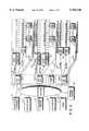
- FIG. 1depicts a three-way channelizer in which three 2 Mhz data channels are combined into one 6 MHz channel and upconverted to an RF frequency in the roll-off band of the television headend equipment.
- television headend equipmentis capable of utilizing television channels ranging in frequency from 44 MHz to top ends of 440 MHz, 550 MHz, 750 MHz, 803 MHz and 1 GHZ.
- the roll-off bandis made up of bandwidth above and below the television channel range of the headend equipment.
- the channelization schemesmay also be altered to accommodate 8 Mhz channels utilized in Europe and elsewhere. Additionally, other channel widths can be used to accommodate the data, such as a 6 MHz channel carrying one data channel.
- three digital data serial streamsare input into three modulators 101A-C.
- the modulatorsuse a common clock to modulate three data input streams by quadrature amplitude modulation (QAM).
- QAMquadrature amplitude modulation
- Other forms of modulationsuch as vestigial side band (e.g., 4VSB or 8VSB modulation), may be used.
- 64QAM modulationprovides a data throughput of about 1.536 or 1.648 megasymbols per second per subchannel.
- each of the modulated data streamsare low pass filtered by filters 102A-C.
- Filters 102A-Care preferably elliptically-shaped Butterworth filters having 7 or 9 poles and a cut-off frequency of about 2.5 MHz.
- the three filtered signalsare then upconverted in upconverters 103A-C using conventional techniques.
- the upconverters 103A-Cupconvert the signals to intermediate frequency (IF) signals centered about 42 MHz (subchannel A), 44 MHz (subchannel B) and 46 MHz (subchannel C), respectively.
- IFintermediate frequency
- the reason that the data streams are modulated and later upconvertedis that present circuit limitations prevent direct modulation using 64 QAM. It is to be understood that the scope of the present invention does not exclude direct QAM modulation to intermediate frequencies (IF) for further conditioning and processing by standard television components.
- IF filters 104A-Care 2 MHz wide surface-acoustic-wave (SAW) filters.
- SAWsurface-acoustic-wave
- the resulting signals on the respective channelsare then combined in adder 105 and again IF filtered by IF filter 106.
- the output of IF filter 106is supplied to upconverter 107 where the IF composite signal is upconverted again using techniques common to an RF frequency in the roll-off band of television headend equipment.
- the frequencycan be above the last usable television channel, or below television channel 2. If multiple channelizers are used in accordance with this invention, both the upper and the lower roll-off band may be used. Although it is possible to utilize the roll-off band with a 30 Mbit/sec bit stream being placed into a 6 Mhz channel, it is preferable to place 10 Mbit/sec bit streams into 2 MHz subchannels because the filter needed on a 6 MHz channel would be cost prohibitive.
- the data recovery circuit of FIG. 2located at a receiving end of a data transmission, it is seen that data received from the network flows to a client over a specific subchannel.
- the particular subchannelis defined by the tuned frequency of tuner 111.
- the incoming RF signalsare supplied to the tuner 111 in which a specific 2 Mhz television subchannel frequency is selected (or tuned).
- tuner 111may tune to the RF frequency of 49 MHz, representing subchannel A of the first 6 MHz channel below television channel 2. That signal is then downconverted to an IF frequency centered at 44 MHz in downconverter 112 and run through an IF filter 113, preferably one matching IF filters 104A-C in FIG. 1.
- the filtered signalis then downconverted at downconverter 115 to baseband and filtered again at filter 116 preferably using a filter matching filters 102A-C used on the modulating end.
- the digital datais then recovered from the baseband signal in data recovery circuit 117 using conventional techniques such as baseband sampling at four, eight or sixteen times the symbol rate.
- three digital data serial streamspreferably each utilizing the same clock signal, are input into three modulators 121A-C.
- These modulators 121A-Cvestigial sideband modulate (VSB) the three input data streams by carriers of 42.950 MHz, 44.950 MHz and 46.950 MHz, respectively.
- VSBvestigial sideband modulate
- 4VSBis utilized.
- any other acceptable form of modulationmay be used.
- IF filters 124A-Care 2 MHz wide surface-acoustic-wave (SAW) filters.
- IF filter 126The output of IF filter 126 is fed to upconverter 127 where the IF composite signal is upconverted again using conventional techniques to an RF frequency in the roll-off band.
- the datathen flows to a client over a specific subchannel.
- the incoming RF signalsare fed into a tuner 131 in which a specific roll-off subchannel frequency is selected. That signal is then downconverted to an IF frequency centered at 44 MHz in downconverter 132 and run through an IF filter 133, preferably one matching IF filters 124A-C in FIG. 3.
- the filtered signalis then fed to synchronous detector 135 followed by low pass filter 136.
- Filter 136is preferably an elliptically-shaped Butterworth filter with 7 or 9 poles and a cut-off frequency of about 2.5 MHz.
- the digital datais then recovered from the baseband signal in data recovery circuit 137 using conventional techniques, such as sampling at two times the symbol rate.
- datamay be transmitted from a client to a television headend facility utilizing as well by modulating (as described above) a single data bit stream for transmission over the roll-off band.
- FIG. 5is a detailed schematic drawing of a hybrid access system 1 in which the channelizer and data recovery device is employed respectively at the cable television headend 28 and a the remote link adapters 29 in order to permit the channelizing of three 2 MHz subchannels into a 6 Mhz channel transmitted from headend 28 via an RF frequency in the roll-off band to plural remote like adapters 29.
- FIG. 5shows a remote link adapter (RLA) and client workstation 29 connected through hybrid access system 1 to a variety of entities connected to a backbone network 20 such as Internet, including information providers 21, corporations 22, government agencies 23, universities 24, and others 25.
- a backbone networkis one which is typically not directly connected to a client.
- Hybrid access system 1includes hybrid access system (HAS) points of presence (POPs) 26 and other points of presence 27.
- HAS POPs 26include individual HAS POPs 26 (1)-26(3) which enable communication over a broadband network, either by upstream and downstream cable communications or by downstream cable and upstream telephone communications or various other hybrid configurations (e.g., wireless or satellite).
- a hybrid access system utilizing the present inventionmay include: (1) a hybrid access configuration which uses the downstream cable television roll-off band and upstream public switch telephone network (PSTN), wireless RF communications or integrated services digital network (ISDN) telephone lines; (2) a hybrid access configuration which uses the downstream wireless television roll-off band and upstream public switch telephone network (PSTN), wireless RF communications or integrated services digital network (ISDN) telephone lines; (3) a hybrid access configuration which uses both the downstream and upstream cable television roll-off band; (4) a hybrid access configuration which uses both the downstream and upstream wireless television roll-off band; and (5) a hybrid access configuration with the downstream satellite television roll-off band and upstream PSTN, wireless RF communications or ISDN telephone channels.
- PSTNpublic switch telephone network
- ISDNintegrated services digital network
- Backbone network 20such as the Internet which includes a plurality of Internet serves 20 connected to HAS POPs 26 each including a plurality of host computers and/or servers, collectively referred to as hybrid servers.
- Hybrid access system 1further includes broadcast units such as, a cable television headend 28, independent upstream channels 28, and RLA 29.
- broadcast unitssuch as, a cable television headend 28, independent upstream channels 28, and RLA 29.
- U.S. Pat. No. 5,347,304 (1994) assigned to Hybrid Networks, Inc., describing an example of an RLA,is hereby expressly referenced and incorporated herein in its entirety.
- An RLAmay receive analog broadcast signals including encoded digital information which the RLA decodes and provides to a data terminal or computer.
- the downstream flow of informationproceeds from HAS POPs 26(1)-26(3) through cable television headend or television transmitters 28 via the television roll-off band or cell sites 30 and through RLA and client workstation 29.
- Upstream information flowproceeds in one case from RLA and client workstation 29 through independent upstream channels 28 to HASPOP 26(1) and then to backbone network 20 along T1 or T3 or other digital lines.
- upstream informationproceeds from client workstation through RLA 29 through the cable television network, and cable television headend 28 to hybrid access system point of presence and then through T1, T3, or other digital lines to backbone network 20.
- the outputs of the cable television headends or television transmitters 28include the use of the high speed downstream broadband RF roll-off band connected to respective remote clients 29.
- Hybrid access system 1further includes a plurality of cell sites 30 connected through high speed links to a corresponding hybrid access system point of presence 5.
- the outputs of cell sites 30include the use of the high speed downstream roll-off band connected to selected remote clients 29.
- a particular remote client 29can be connected via an independent lower speed upstream channel to a hybrid access system point of presence 26 as discussed below or via a similar independent lower speed upstream channel to another point of presence system 27.
- lower speedit is meant as a speed reduced from the speed of the high speed link used to transmit information downstream.
- a particular hybrid access system point of presence 5can be connected via duplex high speed links to a plurality of cable television headends or television transmitters, to a plurality of cell sites 30, or a combination of cable television headends or television transmitters 28 and cell sites 30.
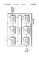
- FIG. 6ais a schematic drawing of a point of presence (POP) system 26(1) according to the present invention, including-host computers or servers 39 and a POP local area network, i.e., LAN switch 33 to which host computers or servers 39 are connected. Further connected to LAN switch 33 are one or more downstream and one or more upstream hybrid access system point of presence routers, respectively 34 and 35, one or more dial-up routers 36, a network management system 37, and conventional routers 38. Connected to POP LAN switch 33 are one or more data storage elements or systems (not shown). Each downstream hybrid access system point of presence router 34 is connected with a high speed link to a television transmitter or cable television headend for transmission of data via the roll-off band for example.
- POPpoint of presence
- each upstream hybrid access system point of presence router 35is connected to a plurality of independent upstream channels, which operate at a lower speed than the downstream high speed links to television transmitters or cable television headends.
- Each dial-up router 36is connected to a plurality of independent upstream channels operating at a lower speed than the indicated downstream high speed links.
- Each conventional router 38is connected along a high speed line to wide area network (WAN) lines to selected information providers, Internet, or other nodes or businesses.
- POP LAN switch 33may be connected directly along a high speed line to wide area network (WAN) lines to selected information providers, Internet, or other nodes or businesses.
- FIG. 6bis a block diagram of hybrid downstream router 34 for use with the present invention.
- downstream router 34includes network interface 34a, link interface 34F, and network interface 34g.
- Downstream router 34 and physical interface 34eare connected to POP LAN switch 33 for sending and receiving information, and physical interface 34e, link interface 34f, and network interface 34g are serially connected to each other and to controller 34d for bi-directional communication of selected information.
- controller 34dis connected directly to each of physical interface 34e and link interface 34f along indicated lines to accomplish control and messaging functions.
- Downstream router 34 and physical interface 34care connected to cable television headends, television broadcast sites, cell cites or the like, to communicate information primarily or exclusively in a unidirectional or downstream direction via the television roll-off band and physical interface 34c, link interface 34b, and network interface 34a are serially connected to each other and to controller 34d for selected communication of selected information. Additionally, controller 34d is connected directly to each of physical interface 34c and link interface 34b along indicated lines to accomplish control and messaging functions. Downstream router 34 may include one or more of physical interfaces 34c. Router 34 may be a bridge without network interfaces 34a and 34g or a connection without network interfaces 34a and 34g and without link interfaces 34b and 34f. Router 34 can also be a gateway.
- FIG. 6cis a block diagram of upstream router 35 for use with the present invention.
- upstream router 35includes network interface 35a, link interface 35b, physical interface 35c, controller 35d, physical interface 35e, link interface 35f, and network interface 35g.
- Upstream router 35 and physical interface 35eare connected to POP LAN switch 33 for sending and receiving information, and physical interface 35e, link interface 35f, and network interface 35g are serially connected to each other and to controller 35d for bi-directional communication of selected information.
- controller 35dis connected directly to each other physical interface 35e and link interface 35f along indicated lines to accomplish control and messaging functions.
- Upstream router 35 and physical interface 35care connected to upsteam channels, e.g.
- Upstream router 35may include one or more of physical interfaces 35c.
- Router 35may be a bridge without network interfaces 35a and 35g or a connection without network interfaces 35a and 35g and without link interfaces 35b and 35f. Router 35 can also be a gateway.
- FIGS. 7a-care drawings of a hybrid access system 1 in which a remote client having a workstation 2 is connected to LAN 61, as shown respectively in FIGS. 7b and 7c, can communicate with a selected information provider 21 including LAN 50, bridge or router 51 connected to LAN 50, and dial-up router 52 connected to LAN 50 through a hybrid access system point of presence 5.
- HAS POP 5is connected along a high speed link to bridge or router 51.
- HAS POP 5is linked to other information providers to receive selected information items.
- dial-up router 52is connected to a plurality of upstream channels.
- first and second clientsadditionally show respective first and second clients, in one case including workstation 2 which includes RLA 60 and in the other instance including RLA 60 and a local area network (LAN) 61 connected to RLA 60.
- First client 29(1)is connected to an upstream channel from client workstation 2
- second client 29(2)is connected to an upstream channel directly from RLA 60.
- RLA 60receives input information, particularly radio frequency (RF) information along one of respective input subchannels in the roll-off band connected thereto.
- RFradio frequency
- any number subchannels or channelscould be used at any reasonable bandwidth.
- these roll-off subchannels or channelsneed not be of uniform bandwidth.
- one subchannelcould be a 4 MHz subchannel and another a 2 MHz subchannel.
- a testwas conducted in which a bit error rate tester was connected to a 64QAM modulator. A 30 Mbit/sec digital data stream was then passed through the modulator and upconverted to an RF signal of a standard television channel frequency within the range of television channels a television headend was capable of utilizing. The RF signal was then downconverted and demodulated at a simulated client. Bit errors in the range of 1 ⁇ 10-5 were experienced. The test configuration was then altered so that the same data stream was upconverted to an RF frequency centered at 483 MHz through a television headend with a top available television channel frequency of 440 MHz. That data stream was recovered at a simulated client and bit errors in the range of 3.8 ⁇ 10-5 were experienced.
- the bit error rate testerwas then connected to a channel divider utilizing 64QAM according to the present invention.
- Three data streams of 10 Mbit/sec eachwere then fed into the respective inputs of the channel divider according to the present invention (as shown in FIG. 1) and one of those bit streams was recovered at a simulated client (as shown in FIG. 2).
- This testwas repeated for each of the three data streams. Under this test of the utilization of subchannels, bit errors in the range of 1 ⁇ 10-8 were experienced.
- the test configurationwas then altered so that the same data streams were then upconverted to an RF frequency centered at 483 MHz through a television headend with a top available television channel frequency of 440 MHz.
- One of the three data streamswas recovered at a simulated client. The test was repeated for each of the three data streams under this test and bit errors in the range of 1.7 ⁇ 10-7 were experienced.
Landscapes
- Engineering & Computer Science (AREA)
- Signal Processing (AREA)
- Multimedia (AREA)
- Computer Networks & Wireless Communication (AREA)
- Two-Way Televisions, Distribution Of Moving Picture Or The Like (AREA)
- Television Systems (AREA)
Abstract
Description
Claims (43)
Priority Applications (3)
| Application Number | Priority Date | Filing Date | Title |
|---|---|---|---|
| US08/735,110US5956346A (en) | 1996-10-22 | 1996-10-22 | Broadband communication system using TV channel roll-off spectrum |
| PCT/US1997/014794WO1998008345A2 (en) | 1996-08-22 | 1997-08-22 | System for use in television roll-off band channels for data transfer over a network |
| AU47994/97AAU4799497A (en) | 1996-08-22 | 1997-08-22 | System for use in television roll-off band channels for data transfer over a network |
Applications Claiming Priority (1)
| Application Number | Priority Date | Filing Date | Title |
|---|---|---|---|
| US08/735,110US5956346A (en) | 1996-10-22 | 1996-10-22 | Broadband communication system using TV channel roll-off spectrum |
Publications (1)
| Publication Number | Publication Date |
|---|---|
| US5956346Atrue US5956346A (en) | 1999-09-21 |
Family
ID=24954405
Family Applications (1)
| Application Number | Title | Priority Date | Filing Date |
|---|---|---|---|
| US08/735,110Expired - Fee RelatedUS5956346A (en) | 1996-08-22 | 1996-10-22 | Broadband communication system using TV channel roll-off spectrum |
Country Status (3)
| Country | Link |
|---|---|
| US (1) | US5956346A (en) |
| AU (1) | AU4799497A (en) |
| WO (1) | WO1998008345A2 (en) |
Cited By (44)
| Publication number | Priority date | Publication date | Assignee | Title |
|---|---|---|---|---|
| JP2000244890A (en)* | 1999-02-16 | 2000-09-08 | Koninkl Philips Electronics Nv | Method for transmitting return signal from video communication signal distribution network to satellite |
| US6157682A (en)* | 1998-03-30 | 2000-12-05 | Nortel Networks Corporation | Wideband receiver with bandwidth extension |
| US6433835B1 (en) | 1998-04-17 | 2002-08-13 | Encamera Sciences Corporation | Expanded information capacity for existing communication transmission systems |
| US20020152303A1 (en)* | 2000-10-17 | 2002-10-17 | Steve Dispensa | Performance management system |
| US6570913B1 (en) | 1999-04-05 | 2003-05-27 | Cisco Technology, Inc. | Method and apparatus for selecting optimum frequency for upstream data transmission in a network system utilizing cable modems |
| US6574797B1 (en) | 1999-01-08 | 2003-06-03 | Cisco Technology, Inc. | Method and apparatus for locating a cleaner bandwidth in a frequency channel for data transmission |
| US20040008765A1 (en)* | 2001-12-18 | 2004-01-15 | Wonzoo Chung | Joint adaptive optimization of soft decision device and feedback equalizer |
| US6742044B1 (en) | 2000-05-10 | 2004-05-25 | Cisco Technology, Inc. | Distributed network traffic load balancing technique implemented without gateway router |
| US6751191B1 (en) | 1999-06-29 | 2004-06-15 | Cisco Technology, Inc. | Load sharing and redundancy scheme |
| US6775840B1 (en) | 1997-12-19 | 2004-08-10 | Cisco Technology, Inc. | Method and apparatus for using a spectrum analyzer for locating ingress noise gaps |
| US6789125B1 (en) | 2000-05-10 | 2004-09-07 | Cisco Technology, Inc. | Distributed network traffic load balancing technique implemented without gateway router |
| US6795858B1 (en) | 2000-12-29 | 2004-09-21 | Cisco Technology, Inc. | Method and apparatus for metric based server selection |
| US20050025179A1 (en)* | 2003-07-31 | 2005-02-03 | Cisco Technology, Inc. | Distributing and balancing traffic flow in a virtual gateway |
| US6981056B1 (en) | 2000-06-28 | 2005-12-27 | Cisco Technology, Inc. | Wide area load balancing of web traffic |
| US7002937B1 (en) | 2000-10-17 | 2006-02-21 | Sprint Communications Company L.P. | Access based on termination in a wireless communication system |
| US7062562B1 (en) | 2001-04-11 | 2006-06-13 | Cisco Technology, Inc. | Methods and apparatus for content server selection |
| US7062571B1 (en) | 2000-06-30 | 2006-06-13 | Cisco Technology, Inc. | Efficient IP load-balancing traffic distribution using ternary CAMs |
| US7069324B1 (en) | 2000-06-30 | 2006-06-27 | Cisco Technology, Inc. | Methods and apparatus slow-starting a web cache system |
| US20060140164A1 (en)* | 2004-12-29 | 2006-06-29 | Cisco Technology, Inc. | Methods and apparatus for using DHCP for home address management of nodes attached to an edge device and for performing mobility and address management as a proxy home agent |
| US7072979B1 (en) | 2000-06-28 | 2006-07-04 | Cisco Technology, Inc. | Wide area load balancing of web traffic |
| US7080138B1 (en) | 2001-04-11 | 2006-07-18 | Cisco Technology, Inc. | Methods and apparatus for content server selection |
| US7085287B1 (en) | 2001-06-27 | 2006-08-01 | Cisco Technology, Inc. | Map routing technique implemented in access networks |
| US7113494B1 (en) | 2000-10-17 | 2006-09-26 | Sprint Communications Company L.P. | Broadband wireless communications using multiple contention channels |
| US20060251097A1 (en)* | 1999-10-13 | 2006-11-09 | Cisco Technology, Inc. | Downstream channel change technique implemented in an access network |
| US7227863B1 (en) | 2001-11-09 | 2007-06-05 | Cisco Technology, Inc. | Methods and apparatus for implementing home agent redundancy |
| US7227838B1 (en) | 2001-12-14 | 2007-06-05 | Cisco Technology, Inc. | Enhanced internal router redundancy |
| US7266080B1 (en) | 2000-10-17 | 2007-09-04 | Sprint Communications Company L.P. | Access based on a rate in a wireless communication system |
| US7287072B1 (en) | 2000-10-17 | 2007-10-23 | Sprint Communications Company L.P. | Remote monitoring information management |
| US7349430B1 (en) | 2001-06-27 | 2008-03-25 | Cisco Technology, Inc. | Addressing scheme implemented in access networks |
| US7395348B1 (en) | 2000-06-05 | 2008-07-01 | Cisco Technology, Inc. | Network cache-based content routing |
| US7580482B2 (en) | 2003-02-19 | 2009-08-25 | Endres Thomas J | Joint, adaptive control of equalization, synchronization, and gain in a digital communications receiver |
| US20090234968A1 (en)* | 2008-03-13 | 2009-09-17 | Cisco Technology, Inc. | Server selection for routing content to a client using application layer redirection |
| US7720997B1 (en) | 2001-12-19 | 2010-05-18 | Cisco Technology, Inc. | Path selection system |
| US7814232B2 (en) | 2003-03-28 | 2010-10-12 | Cisco Technology, Inc. | Network address translation with gateway load distribution |
| US7840988B1 (en) | 2004-05-07 | 2010-11-23 | Cisco Technology, Inc. | Front-end structure for access network line card |
| US7881208B1 (en) | 2001-06-18 | 2011-02-01 | Cisco Technology, Inc. | Gateway load balancing protocol |
| US7966409B1 (en) | 2000-01-18 | 2011-06-21 | Cisco Technology, Inc. | Routing protocol based redundancy design for shared-access networks |
| US8180883B1 (en) | 2004-08-02 | 2012-05-15 | Cisco Technology, Inc. | Method and system for processing directives included in management events |
| USRE44661E1 (en) | 2000-01-18 | 2013-12-24 | Cisco Technology, Inc. | Method for a cable modem to rapidly switch to a backup CMTS |
| US8635305B1 (en) | 2001-12-19 | 2014-01-21 | Cisco Technology, Inc. | Mechanisms for providing differentiated services within a web cache |
| US20160248497A1 (en)* | 2015-02-25 | 2016-08-25 | Sed Systems, A Division Of Calian Ltd. | Multichannel signal modulator for use in broadcast satellite applications |
| US9461732B2 (en) | 2014-08-15 | 2016-10-04 | SEAKR Engineering, Inc. | Integrated mixed-signal ASIC with ADC, DAC, and DSP |
| US10917163B2 (en) | 2014-08-15 | 2021-02-09 | SEAKR Engineering, Inc. | Integrated mixed-signal RF transceiver with ADC, DAC, and DSP and high-bandwidth coherent recombination |
| US20240232108A9 (en)* | 2020-12-09 | 2024-07-11 | Arris Enterprises Llc | Dynamic dma buffer management |
Families Citing this family (1)
| Publication number | Priority date | Publication date | Assignee | Title |
|---|---|---|---|---|
| SE0104420D0 (en) | 2001-12-27 | 2001-12-27 | Dican Internat Ab | Method and device for bidirectional data transfer |
Citations (3)
| Publication number | Priority date | Publication date | Assignee | Title |
|---|---|---|---|---|
| US5530471A (en)* | 1993-10-30 | 1996-06-25 | Ant Nachrichtentechnik Gmbh | Radio and television distribution system |
| US5553064A (en)* | 1994-04-05 | 1996-09-03 | Stanford Telecommunications, Inc. | High speed bidirectional digital cable transmission system |
| US5610916A (en)* | 1995-03-16 | 1997-03-11 | Bell Atlantic Network Services, Inc. | Shared receiving systems utilizing telephone cables as video drops |
Family Cites Families (4)
| Publication number | Priority date | Publication date | Assignee | Title |
|---|---|---|---|---|
| US5557316A (en)* | 1990-09-28 | 1996-09-17 | Ictv, Inc. | System for distributing broadcast television services identically on a first bandwidth portion of a plurality of express trunks and interactive services over a second bandwidth portion of each express trunk on a subscriber demand basis |
| US5528283A (en)* | 1992-06-22 | 1996-06-18 | Alcatel Network Systems, Inc. | Switched video distribution apparatus |
| US5534933A (en)* | 1993-10-26 | 1996-07-09 | Samsung Electronics Co., Ltd. | Apparatus for processing NTSC TV signals having digital signals on quadrature-phase video carrier |
| US5550596A (en)* | 1994-11-25 | 1996-08-27 | Thomson Multimedia Sa | Digital television signal processing system including a co-channel rejection filter |
- 1996
- 1996-10-22USUS08/735,110patent/US5956346A/ennot_activeExpired - Fee Related
- 1997
- 1997-08-22AUAU47994/97Apatent/AU4799497A/ennot_activeAbandoned
- 1997-08-22WOPCT/US1997/014794patent/WO1998008345A2/enactiveApplication Filing
Patent Citations (4)
| Publication number | Priority date | Publication date | Assignee | Title |
|---|---|---|---|---|
| US5530471A (en)* | 1993-10-30 | 1996-06-25 | Ant Nachrichtentechnik Gmbh | Radio and television distribution system |
| US5553064A (en)* | 1994-04-05 | 1996-09-03 | Stanford Telecommunications, Inc. | High speed bidirectional digital cable transmission system |
| US5610916A (en)* | 1995-03-16 | 1997-03-11 | Bell Atlantic Network Services, Inc. | Shared receiving systems utilizing telephone cables as video drops |
| US5646942A (en)* | 1995-03-16 | 1997-07-08 | Bell Atlantic Network Services, Inc. | Simulcast transmission of digital programs to shared antenna receiving systems |
Cited By (73)
| Publication number | Priority date | Publication date | Assignee | Title |
|---|---|---|---|---|
| US6775840B1 (en) | 1997-12-19 | 2004-08-10 | Cisco Technology, Inc. | Method and apparatus for using a spectrum analyzer for locating ingress noise gaps |
| US6157682A (en)* | 1998-03-30 | 2000-12-05 | Nortel Networks Corporation | Wideband receiver with bandwidth extension |
| US6433835B1 (en) | 1998-04-17 | 2002-08-13 | Encamera Sciences Corporation | Expanded information capacity for existing communication transmission systems |
| US20040100588A1 (en)* | 1998-04-17 | 2004-05-27 | Hartson Ted E. | Expanded information capacity for existing communication transmission systems |
| US7333153B2 (en) | 1998-04-17 | 2008-02-19 | Dotcast, Inc. | Expanded information capacity for existing communication transmission systems |
| US6574797B1 (en) | 1999-01-08 | 2003-06-03 | Cisco Technology, Inc. | Method and apparatus for locating a cleaner bandwidth in a frequency channel for data transmission |
| US7509670B1 (en) | 1999-01-08 | 2009-03-24 | Cisco Technology, Inc. | Method and apparatus for locating a cleaner bandwidth in a frequency channel for data transmission |
| US6868255B1 (en)* | 1999-02-16 | 2005-03-15 | Koninklijke Philips Electronics N.V. | Method of transmitting return signals to a satellite from a videocommunication signal distribution network |
| JP2000244890A (en)* | 1999-02-16 | 2000-09-08 | Koninkl Philips Electronics Nv | Method for transmitting return signal from video communication signal distribution network to satellite |
| US6570913B1 (en) | 1999-04-05 | 2003-05-27 | Cisco Technology, Inc. | Method and apparatus for selecting optimum frequency for upstream data transmission in a network system utilizing cable modems |
| US9276834B2 (en) | 1999-06-29 | 2016-03-01 | Cisco Technology, Inc. | Load sharing and redundancy scheme |
| US6751191B1 (en) | 1999-06-29 | 2004-06-15 | Cisco Technology, Inc. | Load sharing and redundancy scheme |
| US8077604B1 (en) | 1999-06-29 | 2011-12-13 | Cisco Technology, Inc. | Load sharing and redundancy scheme |
| US7006431B1 (en) | 1999-06-29 | 2006-02-28 | Cisco Technology, Inc. | Load sharing and redundancy scheme |
| US7672230B2 (en) | 1999-10-13 | 2010-03-02 | Cisco Technology, Inc. | Downstream channel change technique implemented in an access network |
| US7656890B2 (en) | 1999-10-13 | 2010-02-02 | Cisco Technology, Inc. | Downstream channel change technique implemented in an access network |
| US20060251097A1 (en)* | 1999-10-13 | 2006-11-09 | Cisco Technology, Inc. | Downstream channel change technique implemented in an access network |
| US7966409B1 (en) | 2000-01-18 | 2011-06-21 | Cisco Technology, Inc. | Routing protocol based redundancy design for shared-access networks |
| USRE44661E1 (en) | 2000-01-18 | 2013-12-24 | Cisco Technology, Inc. | Method for a cable modem to rapidly switch to a backup CMTS |
| US6789125B1 (en) | 2000-05-10 | 2004-09-07 | Cisco Technology, Inc. | Distributed network traffic load balancing technique implemented without gateway router |
| US6742044B1 (en) | 2000-05-10 | 2004-05-25 | Cisco Technology, Inc. | Distributed network traffic load balancing technique implemented without gateway router |
| US7401159B1 (en) | 2000-05-10 | 2008-07-15 | Cisco Technology, Inc. | Distributed network traffic load balancing technique implemented without gateway router |
| US7725598B2 (en) | 2000-06-05 | 2010-05-25 | Cisco Technology, Inc. | Network cache-based content routing |
| US20080222305A1 (en)* | 2000-06-05 | 2008-09-11 | Cisco Technology, Inc. | Network cache-based content routing |
| US7395348B1 (en) | 2000-06-05 | 2008-07-01 | Cisco Technology, Inc. | Network cache-based content routing |
| US6981056B1 (en) | 2000-06-28 | 2005-12-27 | Cisco Technology, Inc. | Wide area load balancing of web traffic |
| US7072979B1 (en) | 2000-06-28 | 2006-07-04 | Cisco Technology, Inc. | Wide area load balancing of web traffic |
| US7062571B1 (en) | 2000-06-30 | 2006-06-13 | Cisco Technology, Inc. | Efficient IP load-balancing traffic distribution using ternary CAMs |
| US7069324B1 (en) | 2000-06-30 | 2006-06-27 | Cisco Technology, Inc. | Methods and apparatus slow-starting a web cache system |
| US20020152303A1 (en)* | 2000-10-17 | 2002-10-17 | Steve Dispensa | Performance management system |
| US7266080B1 (en) | 2000-10-17 | 2007-09-04 | Sprint Communications Company L.P. | Access based on a rate in a wireless communication system |
| US7287072B1 (en) | 2000-10-17 | 2007-10-23 | Sprint Communications Company L.P. | Remote monitoring information management |
| US7904542B1 (en) | 2000-10-17 | 2011-03-08 | Sprint Communications Company L.P. | Probe device for testing broadband wireless system |
| US7113494B1 (en) | 2000-10-17 | 2006-09-26 | Sprint Communications Company L.P. | Broadband wireless communications using multiple contention channels |
| US7843963B1 (en) | 2000-10-17 | 2010-11-30 | Sprint Communications Company L.P. | Probe device for determining channel information in a broadband wireless system |
| US7002937B1 (en) | 2000-10-17 | 2006-02-21 | Sprint Communications Company L.P. | Access based on termination in a wireless communication system |
| US6795858B1 (en) | 2000-12-29 | 2004-09-21 | Cisco Technology, Inc. | Method and apparatus for metric based server selection |
| US7080138B1 (en) | 2001-04-11 | 2006-07-18 | Cisco Technology, Inc. | Methods and apparatus for content server selection |
| US7062562B1 (en) | 2001-04-11 | 2006-06-13 | Cisco Technology, Inc. | Methods and apparatus for content server selection |
| US7881208B1 (en) | 2001-06-18 | 2011-02-01 | Cisco Technology, Inc. | Gateway load balancing protocol |
| US7085287B1 (en) | 2001-06-27 | 2006-08-01 | Cisco Technology, Inc. | Map routing technique implemented in access networks |
| US7349430B1 (en) | 2001-06-27 | 2008-03-25 | Cisco Technology, Inc. | Addressing scheme implemented in access networks |
| US7672332B1 (en) | 2001-06-27 | 2010-03-02 | Cisco Technology, Inc. | Map routing technique implemented in access networks |
| US7227863B1 (en) | 2001-11-09 | 2007-06-05 | Cisco Technology, Inc. | Methods and apparatus for implementing home agent redundancy |
| US7693048B1 (en) | 2001-12-14 | 2010-04-06 | Cisco Technology, Inc. | Enhanced internal router redundancy |
| US7227838B1 (en) | 2001-12-14 | 2007-06-05 | Cisco Technology, Inc. | Enhanced internal router redundancy |
| US7180942B2 (en) | 2001-12-18 | 2007-02-20 | Dotcast, Inc. | Joint adaptive optimization of soft decision device and feedback equalizer |
| US20040008765A1 (en)* | 2001-12-18 | 2004-01-15 | Wonzoo Chung | Joint adaptive optimization of soft decision device and feedback equalizer |
| USRE42558E1 (en) | 2001-12-18 | 2011-07-19 | Omereen Wireless, Llc | Joint adaptive optimization of soft decision device and feedback equalizer |
| US7720997B1 (en) | 2001-12-19 | 2010-05-18 | Cisco Technology, Inc. | Path selection system |
| US8635305B1 (en) | 2001-12-19 | 2014-01-21 | Cisco Technology, Inc. | Mechanisms for providing differentiated services within a web cache |
| US8194791B2 (en) | 2003-02-19 | 2012-06-05 | Omereen Wireless, Llc | Joint, adaptive control of equalization, synchronization, and gain in a digital communications receiver |
| US7580482B2 (en) | 2003-02-19 | 2009-08-25 | Endres Thomas J | Joint, adaptive control of equalization, synchronization, and gain in a digital communications receiver |
| US7814232B2 (en) | 2003-03-28 | 2010-10-12 | Cisco Technology, Inc. | Network address translation with gateway load distribution |
| US20050025179A1 (en)* | 2003-07-31 | 2005-02-03 | Cisco Technology, Inc. | Distributing and balancing traffic flow in a virtual gateway |
| US7593346B2 (en) | 2003-07-31 | 2009-09-22 | Cisco Technology, Inc. | Distributing and balancing traffic flow in a virtual gateway |
| US7840988B1 (en) | 2004-05-07 | 2010-11-23 | Cisco Technology, Inc. | Front-end structure for access network line card |
| US8180883B1 (en) | 2004-08-02 | 2012-05-15 | Cisco Technology, Inc. | Method and system for processing directives included in management events |
| US8059661B2 (en) | 2004-12-29 | 2011-11-15 | Cisco Technology, Inc. | Methods and apparatus for using DHCP for home address management of nodes attached to an edge device and for performing mobility and address management as a proxy home agent |
| US20060140164A1 (en)* | 2004-12-29 | 2006-06-29 | Cisco Technology, Inc. | Methods and apparatus for using DHCP for home address management of nodes attached to an edge device and for performing mobility and address management as a proxy home agent |
| US8667175B2 (en) | 2008-03-13 | 2014-03-04 | Cisco Technology, Inc. | Server selection for routing content to a client using application layer redirection |
| US20090234968A1 (en)* | 2008-03-13 | 2009-09-17 | Cisco Technology, Inc. | Server selection for routing content to a client using application layer redirection |
| US10218430B2 (en) | 2014-08-15 | 2019-02-26 | SEAKR Engineering, Inc. | Integrated mixed-signal ASIC with DAC and DSP |
| US9461732B2 (en) | 2014-08-15 | 2016-10-04 | SEAKR Engineering, Inc. | Integrated mixed-signal ASIC with ADC, DAC, and DSP |
| US10243650B2 (en) | 2014-08-15 | 2019-03-26 | SEAKR Engineering, Inc. | Integrated mixed-signal ASIC with ADC and DSP |
| US10917163B2 (en) | 2014-08-15 | 2021-02-09 | SEAKR Engineering, Inc. | Integrated mixed-signal RF transceiver with ADC, DAC, and DSP and high-bandwidth coherent recombination |
| US11329718B2 (en) | 2014-08-15 | 2022-05-10 | SEAKR Engineering, Inc. | Integrated mixed-signal ASIC with ADC, DAC, and DSP |
| US11711139B2 (en) | 2014-08-15 | 2023-07-25 | SEAKR Engineering, Inc. | Integrated mixed-signal ASIC with ADC, DAC, and DSP |
| US12255729B2 (en) | 2014-08-15 | 2025-03-18 | Seakr Engineering, Llc | Integrated mixed-signal ASIC with ADC, DAC, and DSP |
| US20160248497A1 (en)* | 2015-02-25 | 2016-08-25 | Sed Systems, A Division Of Calian Ltd. | Multichannel signal modulator for use in broadcast satellite applications |
| US10651927B2 (en)* | 2015-02-25 | 2020-05-12 | Sed Systems, A Division Of Calian Ltd. | Multichannel signal modulator for use in broadcast satellite applications |
| US20240232108A9 (en)* | 2020-12-09 | 2024-07-11 | Arris Enterprises Llc | Dynamic dma buffer management |
| US12265493B2 (en)* | 2020-12-09 | 2025-04-01 | Arris Enterprises Llc | Dynamic DMA buffer management |
Also Published As
| Publication number | Publication date |
|---|---|
| AU4799497A (en) | 1998-03-06 |
| WO1998008345A2 (en) | 1998-02-26 |
| WO1998008345A3 (en) | 1998-07-09 |
Similar Documents
| Publication | Publication Date | Title |
|---|---|---|
| US5956346A (en) | Broadband communication system using TV channel roll-off spectrum | |
| US5959660A (en) | Subchannelization scheme for use in a broadband communications system | |
| WO1998008345A9 (en) | System for use in television roll-off band channels for data transfer over a network | |
| US5825829A (en) | Modulator for a broadband communications system | |
| US9015774B2 (en) | Intelligent device system and method for distribution of digital signals on a wideband signal distribution system | |
| US5521943A (en) | COFDM combined encoder modulation for digital broadcasting sound and video with PSK, PSK/AM, and QAM techniques | |
| WO1998008345B1 (en) | System for use in television roll-off band channels for data transfer over a network | |
| USRE35774E (en) | Remote link adapter for use in TV broadcast data transmission system | |
| EP0763291B1 (en) | Frequency agile broadband communications system | |
| US7298796B2 (en) | Coaxial cable communications systems and methods employing single and multiple sinewave modulation and demodulation techniques | |
| US4092596A (en) | Data transmission and reception system | |
| US6665296B1 (en) | Network access communication system | |
| KR101058819B1 (en) | Multi-Channel Broadband Content Distribution System | |
| US6272681B1 (en) | Cable modem optimized for high-speed data transmission from the home to the cable head | |
| US20020083475A1 (en) | Intelligent device system and method for distribution of digital signals on a wideband signal distribution system | |
| US6496982B1 (en) | Device and method relating to cable TV networks | |
| EP1097591A1 (en) | Optimized system for distributing television and telecommunication services from a peripheral node to user terminals | |
| JP3128602B2 (en) | Digital transmission equipment | |
| KR100237708B1 (en) | Broadband Wireless Subscriber Network System based on Cable Modem | |
| Sari | Some design issues in local multipoint distribution systems | |
| US20220393849A1 (en) | Full duplex wireless communication system with single master clock | |
| JPH0648818B2 (en) | Information transmission method | |
| McMullin | RF and system requirements for cable modem applications | |
| MXPA02006552A (en) | Rf back channel for dtv. | |
| JPH11346212A (en) | Broadband information system for distribution and interaction services |
Legal Events
| Date | Code | Title | Description |
|---|---|---|---|
| AS | Assignment | Owner name:HYBRID NETWORKS, INC., CALIFORNIA Free format text:ASSIGNMENT OF ASSIGNORS INTEREST;ASSIGNOR:LEVAN, WILLIAM;REEL/FRAME:008276/0315 Effective date:19961018 | |
| AS | Assignment | Owner name:HYBR WIRELESS INDUSTRIES LIMITED, CHANNEL ISLANDS Free format text:ASSIGNMENT OF ASSIGNORS INTEREST;ASSIGNOR:LONDON PACIFIC LIFE & ANNUITY COMPANY, A NORTH CAROLINA STOCK LIFE INSURER;REEL/FRAME:013117/0667 Effective date:20020531 | |
| AS | Assignment | Owner name:LONDON PACIFIC LIFE & ANNUITY COMPANY, NORTH CAROL Free format text:ASSIGNMENT OF ASSIGNORS INTEREST;ASSIGNOR:HYBRID NETWORKS, INC.;REEL/FRAME:013117/0854 Effective date:20020521 | |
| FEPP | Fee payment procedure | Free format text:PAT HOLDER CLAIMS SMALL ENTITY STATUS, ENTITY STATUS SET TO SMALL (ORIGINAL EVENT CODE: LTOS); ENTITY STATUS OF PATENT OWNER: LARGE ENTITY | |
| REFU | Refund | Free format text:REFUND - PAYMENT OF MAINTENANCE FEE, 4TH YEAR, LARGE ENTITY (ORIGINAL EVENT CODE: R1551); ENTITY STATUS OF PATENT OWNER: LARGE ENTITY Free format text:REFUND - SURCHARGE FOR LATE PAYMENT, LARGE ENTITY (ORIGINAL EVENT CODE: R1554); ENTITY STATUS OF PATENT OWNER: LARGE ENTITY | |
| REMI | Maintenance fee reminder mailed | ||
| FPAY | Fee payment | Year of fee payment:4 | |
| SULP | Surcharge for late payment | ||
| AS | Assignment | Owner name:HYBRID PATENTS INCORPORATED, TEXAS Free format text:ASSIGNMENT OF ASSIGNORS INTEREST;ASSIGNOR:HYBR WIRELESS INDUSRIES LIMITED;REEL/FRAME:013974/0614 Effective date:20030307 | |
| AS | Assignment | Owner name:HYBRID PATENTS INCORPORATED, TEXAS Free format text:ASSIGNMENT OF ASSIGNORS INTEREST;ASSIGNOR:HYBR WIRELESS INDUSTRIES LIMITED;REEL/FRAME:014532/0235 Effective date:20030307 | |
| FEPP | Fee payment procedure | Free format text:PAT HOLDER NO LONGER CLAIMS SMALL ENTITY STATUS, ENTITY STATUS SET TO UNDISCOUNTED (ORIGINAL EVENT CODE: STOL); ENTITY STATUS OF PATENT OWNER: LARGE ENTITY | |
| REFU | Refund | Free format text:REFUND - PAYMENT OF MAINTENANCE FEE, 8TH YR, SMALL ENTITY (ORIGINAL EVENT CODE: R2552); ENTITY STATUS OF PATENT OWNER: LARGE ENTITY | |
| FPAY | Fee payment | Year of fee payment:8 | |
| REMI | Maintenance fee reminder mailed | ||
| LAPS | Lapse for failure to pay maintenance fees | ||
| STCH | Information on status: patent discontinuation | Free format text:PATENT EXPIRED DUE TO NONPAYMENT OF MAINTENANCE FEES UNDER 37 CFR 1.362 | |
| FP | Lapsed due to failure to pay maintenance fee | Effective date:20110921 |