US5956158A - Scanner powered by peripheral bus - Google Patents
Scanner powered by peripheral busDownload PDFInfo
- Publication number
- US5956158A US5956158AUS08/829,962US82996297AUS5956158AUS 5956158 AUS5956158 AUS 5956158AUS 82996297 AUS82996297 AUS 82996297AUS 5956158 AUS5956158 AUS 5956158A
- Authority
- US
- United States
- Prior art keywords
- platen
- scanner
- motor
- memory
- cis
- Prior art date
- Legal status (The legal status is an assumption and is not a legal conclusion. Google has not performed a legal analysis and makes no representation as to the accuracy of the status listed.)
- Expired - Lifetime
Links
Images


Classifications
- H—ELECTRICITY
- H04—ELECTRIC COMMUNICATION TECHNIQUE
- H04N—PICTORIAL COMMUNICATION, e.g. TELEVISION
- H04N1/00—Scanning, transmission or reproduction of documents or the like, e.g. facsimile transmission; Details thereof
- H04N1/46—Colour picture communication systems
- H04N1/48—Picture signal generators
- H04N1/482—Picture signal generators using the same detector device sequentially for different colour components
- H04N1/484—Picture signal generators using the same detector device sequentially for different colour components with sequential colour illumination of the original
- H—ELECTRICITY
- H04—ELECTRIC COMMUNICATION TECHNIQUE
- H04N—PICTORIAL COMMUNICATION, e.g. TELEVISION
- H04N1/00—Scanning, transmission or reproduction of documents or the like, e.g. facsimile transmission; Details thereof
- H04N1/04—Scanning arrangements, i.e. arrangements for the displacement of active reading or reproducing elements relative to the original or reproducing medium, or vice versa
- H04N1/12—Scanning arrangements, i.e. arrangements for the displacement of active reading or reproducing elements relative to the original or reproducing medium, or vice versa using the sheet-feed movement or the medium-advance or the drum-rotation movement as the slow scanning component, e.g. arrangements for the main-scanning
- H04N1/121—Feeding arrangements
- H04N1/1215—Feeding using one or more cylindrical platens or rollers in the immediate vicinity of the main scanning line
- H—ELECTRICITY
- H04—ELECTRIC COMMUNICATION TECHNIQUE
- H04N—PICTORIAL COMMUNICATION, e.g. TELEVISION
- H04N1/00—Scanning, transmission or reproduction of documents or the like, e.g. facsimile transmission; Details thereof
- H04N1/04—Scanning arrangements, i.e. arrangements for the displacement of active reading or reproducing elements relative to the original or reproducing medium, or vice versa
- H04N1/19—Scanning arrangements, i.e. arrangements for the displacement of active reading or reproducing elements relative to the original or reproducing medium, or vice versa using multi-element arrays
- H04N1/191—Scanning arrangements, i.e. arrangements for the displacement of active reading or reproducing elements relative to the original or reproducing medium, or vice versa using multi-element arrays the array comprising a one-dimensional array, or a combination of one-dimensional arrays, or a substantially one-dimensional array, e.g. an array of staggered elements
- H04N1/192—Simultaneously or substantially simultaneously scanning picture elements on one main scanning line
- H04N1/193—Simultaneously or substantially simultaneously scanning picture elements on one main scanning line using electrically scanned linear arrays, e.g. linear CCD arrays
Definitions
- the present inventionrelates to sheet-fed scanners, and in particular to scanners connected by a peripheral bus to a host computer.
- a typical sheet-fed scannerincludes a roller, or platen, with a resilient, high friction material on the outside of the platen.
- the platenis rotated by a motor to draw paper into the scanner.
- the paperis typically moved between the roller and a contact image sensor (CIS).
- CIScontact image sensor
- the contact image sensorwill typically have a line of LEDs, with different color LEDs for a color scanner. Alternately, fewer or one LED could be used, with an optical element spreading the light to all the pixel positions of a line.
- Such a scannercan either connect to a peripheral bus of a host computer, or could be embedded in a computer, such as being embedded in a laptop.
- a separate power cordwill connect to line power or to the computer's line power in the laptop for providing the power needed to drive the scanner's motor, CIS sensor, and other electronics.
- a number of other different types of peripheral devicesconnect to a computer.
- mice, joysticks, trackballs, touchpads, etc.can be connected to the peripheral port of a computer or embedded in a laptop.
- USBuniversal serial bus
- the recently developed universal serial bus (USB)provides four connectors, two for data and two for power and ground. Power can be obtained from the host computer's 5 volt supply (which is actually 4.5-5.5 volts). However, only 2.2 watts of power are available.
- a typical scannerdue to the high power requirements of the motor for the platen, and the power requirements of the CIS scanner, typically requires in the neighborhood of 12 watts of power, an order of magnitude higher than the power available over the USB.
- the present inventionprovides a scanner powered by the limited power available on a peripheral bus.
- the scanner of the present inventioncan operate within the 2.2 watts provided over a USB connector.
- the present inventionis the result of a unique combination of features and unusual tradeoffs.
- the scanner of the present inventionuses a CIS sensor which uses optics to distribute light from each light emitter to multiple pixel positions, preferably using a single LED for each color.
- An electric motor for driving the platenuses rare earth magnets to limit the power required.
- the plateninstead of the traditional method of biasing the CIS scanner against the platen with a spring, the platen itself is spring-biased.
- the moveable spring biasing of a platenis possible because a worm drive motor is used allowing a helical thread on the worm drive to contact the platen gears as they move up and down as biased.
- the spring biasing of the platenrather than the CIS sensor, eliminates binding, or torque twisting, between the two, thus reducing the torque and required power.
- the helical thread of the worm gearhas a single point of contact with a gear on the platen, further limiting the friction and allowing the platen to move up and down with respect to the stationary motor.
- control circuitry for the scanneris also configured to limit power consumption with non-obvious tradeoffs.
- DACdigital-to-analog converter
- the digital pulses themselvesare used, with their duty cycle being varied and filtered to provide the necessary analog signal.
- only the most significant bits for designating the motor speedare used to limit the amount of circuitry needed to calculate the speed. Although this appears to produce an inaccurate speed, because of the feedback, the correct speed is quickly achieved without impairing performance, while allowing a significant reduction in the number of transistors, capacitance, and accordingly the power consumption of the control circuitry.
- the digital controller circuitalso operates on a 3.3 volt power supply to further reduce power, with the 5 volt power from the host computer being reduced accordingly. Additionally, the sensor drive circuit for the CIS sensor provides different levels of power for different color LEDs, as well as different amounts of time, to even out the intensity of each color and ensure that excess power is not used for any particular color.
- the platen itselfis preferably made of a harder material than a typical scanner to limit the footprint of the platen on the paper (the amount of the platen in contact with the paper due to compression at the point of contact). This reduces the amount of power required to drive the platen, while at the same time providing sufficient friction to grip the paper when used in combination with the other features of the invention. Additionally, a smaller diameter platen than the prior art is used, preferably less than 15 mm and optimally about 13 mm. This reduces the torque-arm of the platen, further reducing the power consumption of the drive motor.
- FIG. 1is a diagram of a computer system incorporating the present invention.
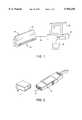
- FIG. 2is a diagram of a USB connector.
- FIG. 3is a perspective, broken-away view of a portion of a scanner according to the present invention.
- FIG. 4is a perspective, exploded view of a scanner according to the present invention.
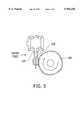
- FIG. 5is a diagram of the worm gear of the present invention.
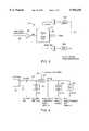
- FIG. 6is a block diagram of the electronic control circuitry of the present invention.
- FIG. 7is a block diagram showing the ASIC of FIG. 6 in more detail.
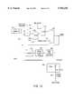
- FIG. 8is a block diagram of the analog signal processor of FIG. 6.
- FIG. 9is a block diagram of the power supply system.
- FIG. 10is a block diagram of the motor speed control DAC replacement circuit.
- FIG. 1is a diagram of a computer system including a scanner 19 according to the present invention.
- the scanneris connected by a bus 34 to a computer 36.
- the computer 36includes a monitor 38 and is controlled by software provided on a disk 40.
- the scannerhas a front side 42 for feeding sheets of the paper, and a back side 44 which could also be used for feeding paper, such as by attaching a sheet feeder, if desired.
- FIG. 1An alternative embodiment to that shown in FIG. 1 would be for a laptop computer (not shown), in which the scanner would be embedded in the laptop, preferably in front of the keyboard on the laptop. In either embodiment, power could be provided over the peripheral bus 34 either externally or internally to the computer.
- FIG. 2illustrates a connector having parts 12 and 14 for a USB.
- the USBincludes four conductors which connect to pins 16.
- Pins 16include two data pins, and a power and ground pin.
- the USBis designated to provide 5 volt power at a maximum of 2.2 watts.
- the data rateis a maximum of 12 mega bits per second.
- a USEis shown, the present invention can be used with other types of parallel ports providing power.
- an SCSI port, a game port, or a modified parallel portmight be used.
- FIGS. 3-5illustrate certain mechanical aspects of the scanner according to the present invention necessary to understand the invention.
- a more detailed description of the mechanical construction of a preferred embodimentis set forth in a copending application entitled "Peripheral Bus Powered Document Scanning Device", filed even date herewith, application Ser. No. 08/831,848, filed Apr. 1, 1997, incorporated herein by reference.
- a brief description of some aspects of the mechanical construction set forth in that applicationare necessary to an understanding of this invention, and will be set forth below. For more details, reference should be made to such copending application.
- FIG. 3is a diagram of a partially assembled scanner 100. This partially assembled view exposes the platen 210 and drive gear 230 attached to one end of the platen. Drive gear 230 interfaces with a helical thread on a worm drive gear 225, which is connected to the shaft of a motor 220. The platen is biased up against CIS module 205 by a pair of springs 240. The figure also shows end plates 115, 120, frame members 105 and 110, and a slot 115a within which a bearing 215 is positioned on top of spring 240.
- FIG. 4is a more detailed, exploded view of the scanner of FIG. 3.
- a bearing rest 235is shown between bearing 215 and spring 240.
- bearings 215are plastic roller bearings which reduce torque and power requirements.
- the inventionuses a weaker spring 240 on the end opposite the motor, further reducing the torque on the motor and thus the required power.
- this spring opposite the motoris approximately 30 percent weaker than the other spring.
- FIG. 4also shows a document arm 250 on a bar 245.
- this arm memberwill rotate the bar, which rotates the document flag, which triggers the sensor 262 providing a signal indicating that a sheet is being fed into the scanner to activate the scanner.
- Only a single document armis placed in the center of the scanner to ensure that the document, especially documents which are narrower than the scanner, are inserted in the center. This avoids differences in friction and torque due to the sheet being between the roller and the CIS sensor on only one side or the other of the scanner, which would allow a slight twisting of the platen due to the spring force. By requiring that the sheet be fed in the center, this effect is minimized.
- FIG. 5shows another view of motor 220 with its worm drive helical thread gear 225 engaging gear 230 connected to the platen.
- the use of a worm driveis not an obvious choice for a low power application, because of the relative inefficiency of a worm drive.
- the particular design of the present inventionprovides for a 48:1 reduction ratio in a very small space to provide an offsetting power reduction.
- the designallows gear 230 to move up and down with respect to stationary helical gear 225 as the platen is biased by springs 240 of FIGS. 3 and 4.
- the teeth of gear 230 and the helical thread of gear 225are designed so that there is a single point of contact at all times (avoiding multiple points of contact), with the peak of the teeth on gear 230 never reaching the root of the thread on gear 225.
- the teethnever jam into the root, and the larger than standard diameter of the tooth on worm 225 ensures that the drive does not disengage.
- the designthus allows gear 230 to move up and down while maintaining the single point of contact, and the single point of contact limits the frictional losses, thus limiting the power required.
- the ability to move the platen up and down with respect to the motorallows the platen to be spring biased against the CIS module, rather than vice-versa, thus minimizing any torque twisting or binding effect, with a corresponding reduction in the required power.
- Motor 220is preferably a rare-earth magnet motor which operates on 5 volts and 1 watt of power.
- the motoris preferably a stepping motor, which preferably provides 20 steps per rotation.
- the size of the step, the 48:1 reduction, and the diameter of the platenpreferably provide a minimal step distance of 1/600 inch.
- the worm driveis preferably a non-enveloping, single start drive, with a single thread tooth helically wound.
- the platen itselfis preferably less than 15 mm in diameter, and more preferably approximately 13 mm, or, more exactly, 12.94 mm.
- a harder rubber overmold with a high durometer ratingis used.
- NBR rubberis used having a durometer reading of 85+/-5 DUA, and a coefficient of friction between the roller and the paper of approximately 0.8.
- the use of a harder rollerprovides a smaller footprint against the paper when the roller or platen is biased against the CIS module with the paper in-between.
- the footprintis the amount that the roller is compressed under pressure from the springs, which provides friction and resistance to the turning of the motor, and thus affects the power. By limiting the footprint to a narrow line, the power consumption is reduced.
- the CIS sensoris preferably designed with a minimum number of LEDs to limit the power consumption.
- some CIS sensorsuse an array of LEDs in a line to illuminate the different pixel positions of the paper.
- an optical elementsuch as a light pipe
- the light emitted by an LEDcan be directed to a number of pixel positions.
- a single LEDcan illuminate all the pixel positions for a particular color LED.
- three LEDsare used, with the preferred colors being blue, green, and red/orange.
- An example of the use of such a light pipeis set forth in a copending application of the same assignee, entitled “Color Scanner Using Both Variable LED Exposure Time And Photodetector Output Compensation", filed Jun.
- FIG. 6is a block diagram of the electronic control circuitry for the present invention.
- an ASIC chip 600has the custom circuitry for providing the processing functions of the invention.
- ASIC 600includes analog control, a data manager, and a host interface.
- the analog controlprovides a motor control signal on lines 608 to motor and motor drivers 220.
- LED timing signals on lines 610 and CIS timing signals on lines 612are provided to LED drivers and CIS sensor 205.
- ASIC 600interfaces over an image data bus 614 to a calibration data and image FIFO memory 618, and over data bus 614 to a USB descriptor memory 620.
- ASIC 600interfaces with a USB transceiver 622, which in turn interfaces with the USB connector 34 connected to the host computer.
- an analog signal processor 624receives an analog video signal output from the sensor on lines 626 and provides the image data on a bus 628 to ASIC 600, which can then store the data in memory 618. Timing signals from ASIC 600 are provided on lines 630 to an ADC 616 in analog processor 624 (see FIG. 8).
- calibration data from memory 618is loaded over a calibration data bus 617 into analog processor 624.
- minimum and maximum values to correct for differences in the intensity of light at different colors provided to each pixel positionare provided.
- the ASIC 600controls the LED and CIS timing to provide more power to the blue LEDs, for example, to compensate for differences in intensity at the same power.
- lesser poweris provided to the higher intensity red/orange LED to limit wasted power. This is described in more detail in the application Ser. No. 08/497,459.
- USB transceiver 622is preferably a driver manufactured by Philips which operates on 3.3 volts.
- USB descriptor memory 620stores the descriptors which would be requested by the host pursuant to the USB interface description in order to describe the peripheral.
- the circuitry of FIG. 6is designed to match the 12 MHz speed of the USB.
- 12 MHzis a relatively slow speed compared to internal switching times of integrated circuits, including integrated circuits designed to operate at 3.3 volts. Since faster switching speeds require more power, the design of this circuitry purposely uses slower switching speed devices to further limit the power consumption.
- a low end, lower speed ASICcan be used, such as Part No. KG 7763, made by Samsung.
- FIG. 7illustrates an internal organization of ASIC 600 in more detail.
- a register bank 646includes data, control, and command registers.
- Memory manager circuit 648is connected to a host interface 606 and a scan engine timing and control block 602, as well as the memories over data bus 614.
- Memory 618includes both calibration and image data. As discussed above, the calibration information is used to calibrate an image data analog-to-digital converter 616 in processor 624 (see FIG. 8), with its associated minimum and maximum value DACs 625.
- the image memorystores the image scan before transmission through the memory manager and the host interface to the host computer. Typically, the scanning speed is related to the available memory space in the image memory in memory 618. If the memory gets close to full, the scanning speed is slowed down and vice versa.
- FIG. 8is a block diagram of the analog signal processor 624 of FIG. 6.
- the video signal on lines 626is provided through an amplifier 627 to analog-to-digital converter 616. From there, digital data is provided over image data bus 628 to ASIC 600. Calibration data on bus 617 is provided to DACs 625A and 625B. These set the minimum and maximum of ADC 616.
- memory buses 614, 617 and 628could all be the same memory bus, with a common address bus 629 (as shown in FIG. 6) determining where the data is being transmitted.
- FIG. 9illustrates the power distribution of the present invention.
- Five volt poweris provided on line 670 from USB cable 34. This power is provided directly to certain circuitry of digital ASIC 600.
- a voltage regulator 634generates 3.3 volts for most of the digital ASIC 600, and also for the USB transceiver circuit 622.
- a switch 672is used to suspend power to the remaining circuitry under the control of a suspend signal on line 674 from ASIC 600.
- the voltage which can be suspendedis provided directly from switch 672 to the image memory, USB memory, DACs and LEDs.
- a voltage converter 676converts the 5 volts into a negative 5 volts which is needed by the LEDs, the CIS sensor, and analog processing circuit 624.
- a filter 678provides the necessary filtered signal needed by the motor itself, as well as the positive 5 volts needed by the analog processing circuit 624, ADC 616 and the CIS sensor.
- Voltage regulator 634provides 3.3 volts to most of the control circuitry. A 3.3 volt level can still be provided when the power slips to 4.5 volts.
- the USBis specified to have the power between 4.5 and 5.5 volts. Thus, the circuitry must be able to deal with this uncertain amount of exact power being provided from the host computer.
- a new method for determining the motor speedis used.
- the midway or some other threshold point of the image buffer or memorywas used, with the motor being accelerated when the image buffer was less than the threshold, and being decelerated when it was more than the threshold, with the threshold position being the triggering point.
- a more optimum method of calculating the speedwhich would use less power, was desired. It was determined that a result-oriented approach drove a design which was effective, yet simple, requiring few components and less power. In particular, the speed is simply a linear function of the emptiness of the image memory.
- the simple binary inversion of an already available parameterprovides the maximum value for the speed calculation circuitry. Since the host computer reads the data in small packets, the image buffer emptiness variable changes smoothly and it becomes in effect the speed yielded by the hardware loop.
- the speed valueis then used to regulate the frequency of the predefined motor waveforms: short periods or high frequency for high speeds and long periods for low speeds.
- the motor inductor currentshave a shape that looks like something between a square wave and a sinewave. These waves are generated by "microstepping" a method of changing currents a little at each step, thus assuring a smooth motor operation.
- This scannerhas only 128 microsteps for a full wave period. Such a low number is possible because the motor currents are generated by an external voltage to current driver.
- the present inventionis dynamically responsive to the USB bandwidth. This bandwidth is not constant, and depends upon what other peripherals are connected to the USB, and their usage of the USB.
- the FIFO memoryprovides data to the host computer as bandwidth is available, the scan engine controls the scanning speed in response to the amount of data in the FIFO memory.
- the present inventiontakes advantage of this characteristic, and can simplify calculations and reduce the number of bits required for certain control information. For example, instead of specifying 16-bits for the speed value of the motor, only the nine most significant bits need be used to provide rough accuracy. Because the motor is adjusted relative to the amount of data in the FIFO, this provides feedback which will adjust quickly for any inaccuracy in the specification of the motor speed.
- the USB protocolcalls for data to be sent in packets of 64 bytes. Accordingly, there is no need to determine whether the FIFO memory is some value under 64 bytes, but merely if it exceeds 64 bytes so there is enough data for a packet. Accordingly, less resolution is needed for this purpose in determining the fullness of the FIFO memory.
- 1K byteis used as the minimum accuracy so that a significant number of packets can be filled before a transmission is initiated.
- the significance of the reduced number of bits for the different types of control informationis the reduction of additional circuitry and power consumption necessary to process the additional bits.
- the capability of the architecture to predefine the video output range through the DACsallows more power savings.
- the DACs outputset the minimum and maximum value for the video input to the ADC
- the use of the extreme binary values 00 and FFwill translate into the maximum video range of 0 to 2.5 volts.
- the LEDs on timewill be adjusted to match this voltage range.
- the binary rangeis reduced (from FF to F0, E0 etc.)
- the calibration procedurewill be forced to reduce the LED on-time in order to reduce the video output and in order to not saturate the ADC. This will result in power saving.
- the binary numberis further reduced image quality may be affected.
- the architectureprovides the ability to tune up the video range for the minimum power consumption that still meets image quality specifications. By maintaining a sufficient signal to noise ratio, image quality is not degraded.
- An adder/subtractor 654combines a speed increment value from a register 662 with a speed value on lines 664. This speed increment value can be set depending on what size steps are desired. Preferably, a range from 0 to 2.55 is provided. In one mode of operation, an accelerate/decelerate signal on lines 666 control adder/subtractor 654. This signal can be determined by when the FIFO buffer passes a threshold.
- a comparator 668is used to compare the output of adder/subtractor 654 with a FIFO available signal on lines 670.
- the FIFO available signalcould indicate simply the emptiness of the image buffer, as discussed above.
- a second comparator 672limits the speed to a maximum specified speed.
- the speed valueis clocked through a gate 674 by a speed clock 676.
- a speed clockhas two programmable values, of every 2.6 or 0.66 milliseconds.
- the speed signal on line 664is provided to a counter 676 which is essentially a microstep generator.
- the outputis provided to a lookup table 678, to select a sinewave value.
- Thisis then provided to a duty cycle generator 680, which is a counter that provides a signal having a duty cycle which is high for an amount of time corresponding to the sinewave digital value from lookup table 678.
- this signalis provided to a filter 682 and to the voltage control line 608.
- Adder/subtractor 654can be implemented as a 2's complement adder. This simplifies the circuitry needed for the subtraction operation.
- the 2's complement adderneed not be completely accurate, providing additional simplification.
- 2's complementis typically done by inverting the number to be subtracted, giving its complement, and adding 1 to it. However, the 1 can be ignored since the result will only be off a single bit, and will be compensated for by feedback, as discussed above.
- the subtractor circuitryis simplified, requiring less transistors and less power consumption.
- the present inventionmay be embodied in other specific forms without departing from the spirit or essential characteristics thereof.
- the inventioncan work with any low power source, not just a low power peripheral bus.
- the inventioncould work with a battery powered unit, for example. Accordingly, the foregoing description is intended to be illustrative, but not limiting, of the scope of the invention as set forth in the following claims.
Landscapes
- Engineering & Computer Science (AREA)
- Multimedia (AREA)
- Signal Processing (AREA)
- Facsimile Scanning Arrangements (AREA)
- Image Input (AREA)
- Facsimiles In General (AREA)
Abstract
Description
Claims (16)
Priority Applications (7)
| Application Number | Priority Date | Filing Date | Title |
|---|---|---|---|
| US08/829,962US5956158A (en) | 1997-04-01 | 1997-04-01 | Scanner powered by peripheral bus |
| TW087104814ATW366644B (en) | 1997-04-01 | 1998-03-31 | Scanner powered by peripheral bus |
| AU70996/98AAU7099698A (en) | 1997-04-01 | 1998-03-31 | Scanner powered by peripheral bus |
| CNB988038951ACN1159903C (en) | 1997-04-01 | 1998-03-31 | Scanner driven by external bus |
| EP98917973AEP1013075A4 (en) | 1997-04-01 | 1998-03-31 | Scanner powered by peripheral bus |
| JP54195498AJP2001526854A (en) | 1997-04-01 | 1998-03-31 | Scanner driven by peripheral bus |
| PCT/US1998/006402WO1998044721A1 (en) | 1997-04-01 | 1998-03-31 | Scanner powered by peripheral bus |
Applications Claiming Priority (1)
| Application Number | Priority Date | Filing Date | Title |
|---|---|---|---|
| US08/829,962US5956158A (en) | 1997-04-01 | 1997-04-01 | Scanner powered by peripheral bus |
Publications (1)
| Publication Number | Publication Date |
|---|---|
| US5956158Atrue US5956158A (en) | 1999-09-21 |
Family
ID=25256009
Family Applications (1)
| Application Number | Title | Priority Date | Filing Date |
|---|---|---|---|
| US08/829,962Expired - LifetimeUS5956158A (en) | 1997-04-01 | 1997-04-01 | Scanner powered by peripheral bus |
Country Status (7)
| Country | Link |
|---|---|
| US (1) | US5956158A (en) |
| EP (1) | EP1013075A4 (en) |
| JP (1) | JP2001526854A (en) |
| CN (1) | CN1159903C (en) |
| AU (1) | AU7099698A (en) |
| TW (1) | TW366644B (en) |
| WO (1) | WO1998044721A1 (en) |
Cited By (38)
| Publication number | Priority date | Publication date | Assignee | Title |
|---|---|---|---|---|
| WO2001024584A1 (en)* | 1999-09-29 | 2001-04-05 | Color Kinetics, Inc. | Systems and methods for calibrating light output by light-emitting diodes |
| US20010030775A1 (en)* | 2000-04-14 | 2001-10-18 | Nobukazu Suzuki | Image reading apparatus and its control method |
| US20020015174A1 (en)* | 2000-08-02 | 2002-02-07 | Kenichi Nanpei | Image reading apparatus and its control method |
| EP1204272A1 (en)* | 2000-11-02 | 2002-05-08 | Syscan Technology (Shenzhen) Co., Limited | Scanner powered from a univeral serial port |
| US6398205B1 (en)* | 1996-12-25 | 2002-06-04 | Minolta Co., Ltd. | Sheet feeder unit |
| US6486977B1 (en)* | 1998-05-18 | 2002-11-26 | Mustek Systems Inc. | Scanner with a built-in microcontroller |
| US20030107779A1 (en)* | 2001-12-11 | 2003-06-12 | Umax Data Systems Inc | Method and system for promoting scanning speed |
| US20030184803A1 (en)* | 2002-03-28 | 2003-10-02 | Brother Kogyo Kabushiki Kaisha | Imaging apparatus having image data storing function |
| US6661537B1 (en) | 1998-09-16 | 2003-12-09 | Hewlett-Packard Development Company, L.P. | Optical scanner with inclined platen |
| US6696982B2 (en)* | 1999-04-07 | 2004-02-24 | Matsushita Electric Industrial Co., Ltd. | Vehicle terminal apparatus and an information transmitting system |
| US6704124B2 (en) | 1998-09-16 | 2004-03-09 | Syscan (Shenzhen) Technology Co., Limited | Mobile scanners |
| US20040085597A1 (en)* | 2002-11-04 | 2004-05-06 | Chen-Ho Lee | Method of removing memory of scanning apparatus |
| US6791724B2 (en) | 2001-06-04 | 2004-09-14 | Hewlett-Packard Development Company, L.P. | Imaging device with media clamp |
| US6791720B1 (en) | 2000-07-28 | 2004-09-14 | Lite-On Technology Corporation | Portable scanning apparatus |
| US6809844B1 (en)* | 1999-09-15 | 2004-10-26 | Avision Inc. | Scanner which adjusts the image induced voltage by controlling the exposure time of the sensors |
| US20050073792A1 (en)* | 2003-10-02 | 2005-04-07 | Randolph Bullock | EMC immunity improvements to USB interface |
| US20050141208A1 (en)* | 2003-10-14 | 2005-06-30 | Susumu Niinuma | Electronic device including interface terminal and power supply cable connected thereto |
| US20050162715A1 (en)* | 1998-11-11 | 2005-07-28 | Canon Kabushiki Kaisha | Control method for document scanning device |
| US20050174613A1 (en)* | 2004-02-05 | 2005-08-11 | Tan Hin L. | Digital scanning systems and methods for scanning multi-sided cards and documents |
| US20060012819A1 (en)* | 2004-07-13 | 2006-01-19 | Haas William R | Imaging device power management system and method |
| US20060098224A1 (en)* | 2004-11-09 | 2006-05-11 | Konica Minolta Business Technologies, Inc. | Image processing system, image processor and image processing program |
| US20060238830A1 (en)* | 2005-04-21 | 2006-10-26 | Peter Dikeman | Color image capture system |
| US20070070435A1 (en)* | 2001-11-01 | 2007-03-29 | Kuo-Jeng Wang | Method and system for increasing scanning speed |
| US7227634B2 (en) | 2002-08-01 | 2007-06-05 | Cunningham David W | Method for controlling the luminous flux spectrum of a lighting fixture |
| US7240444B1 (en)* | 2004-07-12 | 2007-07-10 | Rodriguez Jose R | Computer typing aid |
| US20080144916A1 (en)* | 2002-11-27 | 2008-06-19 | 3M Innovative Properties Company | Loading and ejection systems for biological growth plate scanner |
| US20080297644A1 (en)* | 2004-06-30 | 2008-12-04 | Nadir Farchtchian | Light-Emitting Diode Arrangement, Optical Recording Device and Method for the Pulsed Operation of at Least One Light-Emitting Diode |
| US20090135603A1 (en)* | 2002-11-27 | 2009-05-28 | 3M Innovative Properties Company | Back side plate illumination for biological growth plate scanner |
| US20100056049A1 (en)* | 2008-09-04 | 2010-03-04 | Darwin Hu | Wireless Mobile Telescanners |
| US20100238519A1 (en)* | 2001-07-31 | 2010-09-23 | Kuo-Jeng Wang | Scanning speed control device and method |
| US20110102582A1 (en)* | 2002-11-27 | 2011-05-05 | 3M Innovative Properties Company | Biological growth plate scanner |
| US20110153220A1 (en)* | 2008-03-04 | 2011-06-23 | Bolea Phillip A | Processing of biological growth media based on measured manufacturing characteristics |
| US20110206263A1 (en)* | 2003-09-05 | 2011-08-25 | 3M Innovative Properties Company | Counting biological agents on biological growth plates |
| US20110205603A1 (en)* | 2010-01-19 | 2011-08-25 | Shifrin Rafael | Sheet-fed laptop scanner |
| US20110222095A1 (en)* | 2010-03-10 | 2011-09-15 | Thomas Sheng | Multifunction device for quick execution of functions and execution method thereof |
| DE102011001399A1 (en)* | 2011-03-18 | 2012-09-20 | Universität Siegen | Signal generator for simultaneous generation of voltages, has control unit that temporally generates controllable clock signal for controlling updating of parameter data of digital/analog converter |
| US8355183B2 (en) | 2001-07-31 | 2013-01-15 | Transpacific Systems, Llc | Scanning speed control device and method |
| US8417013B2 (en) | 2008-03-04 | 2013-04-09 | 3M Innovative Properties Company | Information management in automated processing of biological growth media |
Families Citing this family (4)
| Publication number | Priority date | Publication date | Assignee | Title |
|---|---|---|---|---|
| CN100337195C (en)* | 2002-08-14 | 2007-09-12 | 虹光精密工业(苏州)有限公司 | Typesetting work application program of image and document produced by scanning of several scanning instruments at the time and its method |
| CN100389431C (en)* | 2003-03-24 | 2008-05-21 | 虹光精密工业〔苏州〕有限公司 | Scanning instrument capable of regulating scanning unit position |
| CN107809557A (en)* | 2011-04-15 | 2018-03-16 | 上海派腾特商务咨询有限公司 | Mini scanner |
| US10747366B2 (en)* | 2015-11-23 | 2020-08-18 | Hewlett-Packard Development Company, L.P. | Calibration data identification |
Citations (6)
| Publication number | Priority date | Publication date | Assignee | Title |
|---|---|---|---|---|
| US4733308A (en)* | 1985-08-14 | 1988-03-22 | Hitachi, Ltd. | Control method of vertical scan speed |
| US5239387A (en)* | 1989-11-30 | 1993-08-24 | Hewlett-Packard Company | Buffering control for accommodating variable data exchange rates |
| US5495347A (en)* | 1991-11-06 | 1996-02-27 | Gold Star Co., Ltd. | Color contact image sensor |
| US5537229A (en)* | 1990-04-20 | 1996-07-16 | Nikon Corporation | Method and apparatus for rapid scanning of color images |
| US5612811A (en)* | 1992-06-10 | 1997-03-18 | Nikon Corporation | Scanning device |
| US5729361A (en)* | 1995-06-30 | 1998-03-17 | Logitech, Inc. | Color scanner using both variable led exposure time and photo detector output compensation |
Family Cites Families (1)
| Publication number | Priority date | Publication date | Assignee | Title |
|---|---|---|---|---|
| KR920005856B1 (en)* | 1988-04-25 | 1992-07-23 | 소니 가부시기가이샤 | Color picture reading device |
- 1997
- 1997-04-01USUS08/829,962patent/US5956158A/ennot_activeExpired - Lifetime
- 1998
- 1998-03-31JPJP54195498Apatent/JP2001526854A/ennot_activeCeased
- 1998-03-31WOPCT/US1998/006402patent/WO1998044721A1/ennot_activeApplication Discontinuation
- 1998-03-31AUAU70996/98Apatent/AU7099698A/ennot_activeAbandoned
- 1998-03-31CNCNB988038951Apatent/CN1159903C/ennot_activeExpired - Fee Related
- 1998-03-31TWTW087104814Apatent/TW366644B/ennot_activeIP Right Cessation
- 1998-03-31EPEP98917973Apatent/EP1013075A4/ennot_activeWithdrawn
Patent Citations (6)
| Publication number | Priority date | Publication date | Assignee | Title |
|---|---|---|---|---|
| US4733308A (en)* | 1985-08-14 | 1988-03-22 | Hitachi, Ltd. | Control method of vertical scan speed |
| US5239387A (en)* | 1989-11-30 | 1993-08-24 | Hewlett-Packard Company | Buffering control for accommodating variable data exchange rates |
| US5537229A (en)* | 1990-04-20 | 1996-07-16 | Nikon Corporation | Method and apparatus for rapid scanning of color images |
| US5495347A (en)* | 1991-11-06 | 1996-02-27 | Gold Star Co., Ltd. | Color contact image sensor |
| US5612811A (en)* | 1992-06-10 | 1997-03-18 | Nikon Corporation | Scanning device |
| US5729361A (en)* | 1995-06-30 | 1998-03-17 | Logitech, Inc. | Color scanner using both variable led exposure time and photo detector output compensation |
Cited By (57)
| Publication number | Priority date | Publication date | Assignee | Title |
|---|---|---|---|---|
| US6398205B1 (en)* | 1996-12-25 | 2002-06-04 | Minolta Co., Ltd. | Sheet feeder unit |
| US6486977B1 (en)* | 1998-05-18 | 2002-11-26 | Mustek Systems Inc. | Scanner with a built-in microcontroller |
| US6459506B1 (en) | 1998-09-16 | 2002-10-01 | Syscan, Inc. | Lightweight dual-mode mobile scanner powered from a universal serial bus port |
| US6704124B2 (en) | 1998-09-16 | 2004-03-09 | Syscan (Shenzhen) Technology Co., Limited | Mobile scanners |
| US6661537B1 (en) | 1998-09-16 | 2003-12-09 | Hewlett-Packard Development Company, L.P. | Optical scanner with inclined platen |
| US20050162715A1 (en)* | 1998-11-11 | 2005-07-28 | Canon Kabushiki Kaisha | Control method for document scanning device |
| US7742201B2 (en)* | 1998-11-11 | 2010-06-22 | Canon Kabushiki Kaisha | Control method for document scanning device |
| US6696982B2 (en)* | 1999-04-07 | 2004-02-24 | Matsushita Electric Industrial Co., Ltd. | Vehicle terminal apparatus and an information transmitting system |
| US6809844B1 (en)* | 1999-09-15 | 2004-10-26 | Avision Inc. | Scanner which adjusts the image induced voltage by controlling the exposure time of the sensors |
| WO2001024584A1 (en)* | 1999-09-29 | 2001-04-05 | Color Kinetics, Inc. | Systems and methods for calibrating light output by light-emitting diodes |
| US7482565B2 (en) | 1999-09-29 | 2009-01-27 | Philips Solid-State Lighting Solutions, Inc. | Systems and methods for calibrating light output by light-emitting diodes |
| US6995877B2 (en)* | 2000-04-14 | 2006-02-07 | Canon Kabushiki Kaisha | Image reading apparatus and its control method |
| US20010030775A1 (en)* | 2000-04-14 | 2001-10-18 | Nobukazu Suzuki | Image reading apparatus and its control method |
| US6791720B1 (en) | 2000-07-28 | 2004-09-14 | Lite-On Technology Corporation | Portable scanning apparatus |
| US20020015174A1 (en)* | 2000-08-02 | 2002-02-07 | Kenichi Nanpei | Image reading apparatus and its control method |
| EP1204272A1 (en)* | 2000-11-02 | 2002-05-08 | Syscan Technology (Shenzhen) Co., Limited | Scanner powered from a univeral serial port |
| US6791724B2 (en) | 2001-06-04 | 2004-09-14 | Hewlett-Packard Development Company, L.P. | Imaging device with media clamp |
| US8218183B2 (en)* | 2001-07-31 | 2012-07-10 | Transpacific Systems, Llc | Scanning speed control device and method |
| US20100238519A1 (en)* | 2001-07-31 | 2010-09-23 | Kuo-Jeng Wang | Scanning speed control device and method |
| US8355183B2 (en) | 2001-07-31 | 2013-01-15 | Transpacific Systems, Llc | Scanning speed control device and method |
| US20070070435A1 (en)* | 2001-11-01 | 2007-03-29 | Kuo-Jeng Wang | Method and system for increasing scanning speed |
| US20060268355A1 (en)* | 2001-12-11 | 2006-11-30 | Transpacific Ip, Ltd. | Method and system for promoting scanning speed |
| US7420715B2 (en)* | 2001-12-11 | 2008-09-02 | Transpacific Ip, Ltd. | Method and system for promoting scanning speed |
| US20030107779A1 (en)* | 2001-12-11 | 2003-06-12 | Umax Data Systems Inc | Method and system for promoting scanning speed |
| US7911643B2 (en)* | 2002-03-28 | 2011-03-22 | Brother Kogyo Kabushiki Kaisha | Imaging apparatus having image data storing function |
| US20030184803A1 (en)* | 2002-03-28 | 2003-10-02 | Brother Kogyo Kabushiki Kaisha | Imaging apparatus having image data storing function |
| US7227634B2 (en) | 2002-08-01 | 2007-06-05 | Cunningham David W | Method for controlling the luminous flux spectrum of a lighting fixture |
| US20040085597A1 (en)* | 2002-11-04 | 2004-05-06 | Chen-Ho Lee | Method of removing memory of scanning apparatus |
| US7460257B2 (en) | 2002-11-04 | 2008-12-02 | Chen-Ho Lee | Technique for transferring image information from a scanning apparatus |
| US8759080B2 (en) | 2002-11-27 | 2014-06-24 | 3M Innovative Properties Company | Back side plate illumination for biological growth plate scanner |
| US20110102582A1 (en)* | 2002-11-27 | 2011-05-05 | 3M Innovative Properties Company | Biological growth plate scanner |
| US20080144916A1 (en)* | 2002-11-27 | 2008-06-19 | 3M Innovative Properties Company | Loading and ejection systems for biological growth plate scanner |
| US20090135603A1 (en)* | 2002-11-27 | 2009-05-28 | 3M Innovative Properties Company | Back side plate illumination for biological growth plate scanner |
| US8094916B2 (en)* | 2002-11-27 | 2012-01-10 | 3M Innovative Properties Company | Biological growth plate scanner |
| US20110206263A1 (en)* | 2003-09-05 | 2011-08-25 | 3M Innovative Properties Company | Counting biological agents on biological growth plates |
| US8260026B2 (en) | 2003-09-05 | 2012-09-04 | 3M Innovative Properties Company | Counting biological agents on biological growth plates |
| US7085117B2 (en)* | 2003-10-02 | 2006-08-01 | Axiohm Transaction Solutions, Inc. | EMC immunity improvements to USB interface |
| US20050073792A1 (en)* | 2003-10-02 | 2005-04-07 | Randolph Bullock | EMC immunity improvements to USB interface |
| US20050141208A1 (en)* | 2003-10-14 | 2005-06-30 | Susumu Niinuma | Electronic device including interface terminal and power supply cable connected thereto |
| US7329969B2 (en)* | 2003-10-15 | 2008-02-12 | Teac Corporation | Electronic device including interface terminal and power supply cable connected thereto |
| US20050174613A1 (en)* | 2004-02-05 | 2005-08-11 | Tan Hin L. | Digital scanning systems and methods for scanning multi-sided cards and documents |
| US7505162B2 (en)* | 2004-02-05 | 2009-03-17 | Electronic Document Technology Pte., Ltd. | Digital scanning systems and methods for scanning multi-sided cards and documents |
| US20080297644A1 (en)* | 2004-06-30 | 2008-12-04 | Nadir Farchtchian | Light-Emitting Diode Arrangement, Optical Recording Device and Method for the Pulsed Operation of at Least One Light-Emitting Diode |
| US8482663B2 (en)* | 2004-06-30 | 2013-07-09 | Osram Opto Semiconductors Gmbh | Light-emitting diode arrangement, optical recording device and method for the pulsed operation of at least one light-emitting diode |
| US7240444B1 (en)* | 2004-07-12 | 2007-07-10 | Rodriguez Jose R | Computer typing aid |
| GB2416934A (en)* | 2004-07-13 | 2006-02-08 | Hewlett Packard Development Co | Power management system for an imaging device |
| US20060012819A1 (en)* | 2004-07-13 | 2006-01-19 | Haas William R | Imaging device power management system and method |
| US20060098224A1 (en)* | 2004-11-09 | 2006-05-11 | Konica Minolta Business Technologies, Inc. | Image processing system, image processor and image processing program |
| US8179544B2 (en)* | 2004-11-09 | 2012-05-15 | Konica Minolta Business Technologies, Inc. | Image processing system, image processor and image processing program |
| US20060238830A1 (en)* | 2005-04-21 | 2006-10-26 | Peter Dikeman | Color image capture system |
| US20110153220A1 (en)* | 2008-03-04 | 2011-06-23 | Bolea Phillip A | Processing of biological growth media based on measured manufacturing characteristics |
| US8417013B2 (en) | 2008-03-04 | 2013-04-09 | 3M Innovative Properties Company | Information management in automated processing of biological growth media |
| US9933446B2 (en) | 2008-03-04 | 2018-04-03 | 3M Innovative Properties Company | Processing of biological growth media based on measured manufacturing characteristics |
| US20100056049A1 (en)* | 2008-09-04 | 2010-03-04 | Darwin Hu | Wireless Mobile Telescanners |
| US20110205603A1 (en)* | 2010-01-19 | 2011-08-25 | Shifrin Rafael | Sheet-fed laptop scanner |
| US20110222095A1 (en)* | 2010-03-10 | 2011-09-15 | Thomas Sheng | Multifunction device for quick execution of functions and execution method thereof |
| DE102011001399A1 (en)* | 2011-03-18 | 2012-09-20 | Universität Siegen | Signal generator for simultaneous generation of voltages, has control unit that temporally generates controllable clock signal for controlling updating of parameter data of digital/analog converter |
Also Published As
| Publication number | Publication date |
|---|---|
| AU7099698A (en) | 1998-10-22 |
| CN1159903C (en) | 2004-07-28 |
| EP1013075A1 (en) | 2000-06-28 |
| CN1256838A (en) | 2000-06-14 |
| WO1998044721A1 (en) | 1998-10-08 |
| TW366644B (en) | 1999-08-11 |
| EP1013075A4 (en) | 2003-04-02 |
| JP2001526854A (en) | 2001-12-18 |
Similar Documents
| Publication | Publication Date | Title |
|---|---|---|
| US5956158A (en) | Scanner powered by peripheral bus | |
| US5182450A (en) | Handheld image scanner with automatic movement control | |
| US5999203A (en) | Printer assembly with easily loaded paper cartridge | |
| TW577034B (en) | Liquid crystal display adaptive to visual field angle | |
| EP0641114B1 (en) | Low cost scanner for existing ink jet printer | |
| US8006106B2 (en) | Method and system for flexibly supplying power to a high-end graphics card using an off-card voltage converter module | |
| US6275309B1 (en) | Lightweight mobile scanners | |
| CN1639759A (en) | Configurable panel controller and flexible display interface | |
| US7227550B2 (en) | Processing module for a computer system device | |
| KR19990083056A (en) | A control circuitry for reducing power and electromagnetic interference in conveying video data | |
| WO2004019271A2 (en) | Intra-oral camera coupled directly and independently to a computer | |
| US20100232485A1 (en) | Single conductor bidirectional communication link | |
| CN101206848B (en) | Multi-color gamut control display | |
| US20030074588A1 (en) | Electronic apparatus capable of using an external power source and a bus power source simultaneously | |
| TW529288B (en) | Image reading apparatus and its control method | |
| KR100239119B1 (en) | The communication of monitor and pc | |
| EP0336403B1 (en) | Image reading apparatus | |
| CN1893605A (en) | Electronic apparatus and control method thereof | |
| JPH0566853A (en) | Portable small-sized data processor | |
| US8314582B2 (en) | Method of controlling motor in image reading apparatus | |
| JP2001223837A (en) | Picture reader provided with usb interface means | |
| JP3703260B2 (en) | Image processing device | |
| US20020079858A1 (en) | Scanner that controls stepping motor torque | |
| KR200327350Y1 (en) | Pan/tilt camera haven't serial port connection jack | |
| JPH07283910A (en) | Image input device |
Legal Events
| Date | Code | Title | Description |
|---|---|---|---|
| AS | Assignment | Owner name:LOGITECH INCORPORATED, CALIFORNIA Free format text:ASSIGNMENT OF ASSIGNORS INTEREST;ASSIGNORS:MCVICAR, DAVID;MAGGI, SERGIO;REUSENS, EMMANUEL;AND OTHERS;REEL/FRAME:008745/0981;SIGNING DATES FROM 19970828 TO 19970909 | |
| AS | Assignment | Owner name:STORM TECHNOLOGY, INC., CALIFORNIA Free format text:ASSIGNMENT OF ASSIGNORS INTEREST;ASSIGNOR:LOGITECH, INC.;REEL/FRAME:009038/0553 Effective date:19980312 | |
| STCF | Information on status: patent grant | Free format text:PATENTED CASE | |
| AS | Assignment | Owner name:SILITEK CORPORATION, TAIWAN Free format text:ASSIGNMENT OF ASSIGNORS INTEREST;ASSIGNOR:ROBERTSON, JEROME E., TRUSTEE IN BANKRUPTCY FOR STORM TECHNOLOGIES, INC.;REEL/FRAME:012447/0810 Effective date:20010320 | |
| FEPP | Fee payment procedure | Free format text:PAT HOLDER NO LONGER CLAIMS SMALL ENTITY STATUS, ENTITY STATUS SET TO UNDISCOUNTED (ORIGINAL EVENT CODE: STOL); ENTITY STATUS OF PATENT OWNER: LARGE ENTITY | |
| FPAY | Fee payment | Year of fee payment:4 | |
| AS | Assignment | Owner name:LITE-ON TECHNOLOGY CORPORATION, TAIWAN Free format text:MERGER;ASSIGNOR:SILITEK CORPORATION;REEL/FRAME:014499/0322 Effective date:20021113 | |
| FPAY | Fee payment | Year of fee payment:8 | |
| FPAY | Fee payment | Year of fee payment:12 |