US5956122A - Iris recognition apparatus and method - Google Patents
Iris recognition apparatus and methodDownload PDFInfo
- Publication number
- US5956122A US5956122AUS09/105,062US10506298AUS5956122AUS 5956122 AUS5956122 AUS 5956122AUS 10506298 AUS10506298 AUS 10506298AUS 5956122 AUS5956122 AUS 5956122A
- Authority
- US
- United States
- Prior art keywords
- view
- field
- human
- iris
- light
- Prior art date
- Legal status (The legal status is an assumption and is not a legal conclusion. Google has not performed a legal analysis and makes no representation as to the accuracy of the status listed.)
- Expired - Lifetime
Links
Images


Classifications
- A—HUMAN NECESSITIES
- A61—MEDICAL OR VETERINARY SCIENCE; HYGIENE
- A61B—DIAGNOSIS; SURGERY; IDENTIFICATION
- A61B3/00—Apparatus for testing the eyes; Instruments for examining the eyes
- A61B3/10—Objective types, i.e. instruments for examining the eyes independent of the patients' perceptions or reactions
- A61B3/12—Objective types, i.e. instruments for examining the eyes independent of the patients' perceptions or reactions for looking at the eye fundus, e.g. ophthalmoscopes
- A61B3/1216—Objective types, i.e. instruments for examining the eyes independent of the patients' perceptions or reactions for looking at the eye fundus, e.g. ophthalmoscopes for diagnostics of the iris
- G—PHYSICS
- G06—COMPUTING OR CALCULATING; COUNTING
- G06V—IMAGE OR VIDEO RECOGNITION OR UNDERSTANDING
- G06V40/00—Recognition of biometric, human-related or animal-related patterns in image or video data
- G06V40/10—Human or animal bodies, e.g. vehicle occupants or pedestrians; Body parts, e.g. hands
- G06V40/18—Eye characteristics, e.g. of the iris
- G06V40/19—Sensors therefor
Definitions
- the present inventionrelates to apparatus and methods for determining whether a person is recognized by reference to the eyes of this person. More particularly, the present invention relates to apparatus and methods for recognizing humans by their distinct and individual iris patterns. Most specifically, the present invention relates to an apparatus and method for determining where in a field of view the eyes of a person to be recognized are located, so that closer inspection of the eyes and of the iris of at least one of these eyes can be conducted for recognition purposes.
- the IriScan technologyis believed to require a person who wishes to be identified to look with a selected eye through a portal.
- the portalleads into a machine which captures an image of the iris of the eye so presented.
- the Sensar Companyis believed to use IriScan technology in their Sensar Secure identification system.
- Another system believed to by similaris offered by Oki Electric Industries Co. Ltd. Of Japan, and is known as an Iris Personal Identification System. This latter system is believed to rely upon a video camera which captures a visible light image of the subject, and a pattern recognition software which picks out the subjects face from the background image. Once the subject's face is identified in the field of view then further pattern recognition is conducted to identify and locate a selected eye on the subject's face.
- This locationis then provided to a servo system which directs a fine-focus telephoto video camera toward the location of the person's selected eye.
- This fine focus video camerathen captures an image of the selected eye of the subject, including the iris of this eye, for further processing into a "bar code" pattern which allows definite recognition of the subject.
- the image processing burden on an identification systemis substantial in order to pick out the person's face, and the selected eye of a person, and to do this job fast enough to allow such a system to be accepted for use.
- the systemscan be used at airports for passenger identification, and at ATM machines, for example.
- the identification of the person before the machinemust be performed in a matter of a few seconds, or desirably less.
- the pattern recognition softwaremistakenly directs the fine focus video camera to a location other than the selected eye of the person, the system will not capture an image of an eye it can recognize even when the subject should be recognizable to the system.
- This inability of the current technology to reliably and quickly locate a selected eye of a person within a field of view to be surveyedrepresents a serious shortcoming in the conventional technology, and one which must be overcome if iris identification systems are to receive widespread public acceptance.
- the present inventionprovides a method of locating human iris in a field of view including the steps of beaming light into the field of view, causing the beamed light to be reflected in part from the retina of a human in the field of view, and detecting the reflection of this beamed light from the retina of a person in the field of view.
- this inventionprovides apparatus for locating and identifying a human by reference to the iris pattern of the human in a field of view of the apparatus, and including a projector for beaming light into the field of view, a detector for detecting the reflection of the beamed light from the retina of a human in the field of view and producing a detection signal, processing means for determining from the detection signal the direction to the iris of the human in the field of view, and this processor providing servo signals to a servo driving a camera to align with the direction of the human iris in the field of view.
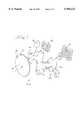
- FIG. 1provides a perspective and somewhat diagrammatic view of a human approaching a kiosk (such as a banking ATM machine) which embodies a iris recognition apparatus according to the present invention
- FIG. 2is a fragmentary view of the face of the human seen in FIG. 1, but is taken from the point of view of the machine seen in FIG. 1;
- FIG. 3is a diagrammatic representation of the face of the human and a surrounding field of view as seen in FIG. 2, and as viewed in near-infrared light;
- FIG. 3aprovides a ray-trace diagram of light entering a human eye, and being in part reflected from the retina of this eye;
- FIG. 4provides a fragmentary and diagrammatic view of the image of a human iris as this image is produced on a component of the apparatus;
- FIG. 5is an extreme close up view of the iris of the human's right eye as seen in FIG. 2, and is presented as this iris is viewed by a visible-light video camera of the apparatus;
- FIG. 6is a schematic view of certain elements of the apparatus.
- FIGS. 7 and 8each present respective schematic illustrations of alternative embodiments of the invention.
- FIG. 1Viewing first FIG. 1 for an overview of the context in which the present invention may be found, it is seen that a human 10 is approaching a machine kiosk 12, which may be a bank ATM, an airline ticket dispensing machine, a security station, or another type of machine needing to recognize the people who want to use is or who pass by it, for example.
- the kiosk 12is merely exemplary, and that apparatus 12a embodying the present invention may be utilized in contexts other than a bank ATM.
- the recognition apparatus 12a embodying the present inventionmight be utilized at an airport to identify persons who want to buy tickets, or passengers who are ticketed to board a particular aircraft, or to identify authorized airport personnel who have access to the baggage loading area or aircraft maintenance area of an airport.
- Other contexts in which apparatus 12a embodying the present invention might be usedare industrial, government, police, or military sites where access to the site or facility is to be controlled. Such access can be controlled by reference to the identification of personnel by use of their unique and individual iris patterns.
- the apparatus 12a within machine 12includes a motion detector 14 so that the approach of the human 10 is detected.
- This detection of an approaching personcan a greeting image to be displayed on a display screen 16 (perhaps along with an audio greeting issued from a speaker 18).
- the human 10is prompted to look toward this area of the apparatus 12a.
- Adjacent to the screen 16are located both an infrared detector 20 and a visible light fine-focus video camera 22. The detector 20 and camera 22 are close together so that parallax is not significant between the points of view of these two devices.
- the detector 20 and camera 22may be partially or fully concealed beneath a transparent (and possibly outwardly reflective) window of the machine 12.
- the human 10may not be aware of the apparatus 12a, or of the mechanism by which the machine 12 will recognize this person.
- FIG. 2the face of the human 10 is seen from the point of view of the machine 12. It will be understood that the machine 12 does not actually obtain or detect the full facial view of the human 10 as is seen in FIG. 2, and that this drawing Figure is simply provided for purposes of explanation and better understanding of the machine 12.
- the human face seen in FIG. 2has two eyes, a selected one of which is to be precisely located so that the image of the iris of this eye can be captured and converted into a somewhat circular version of a "bar code.”
- the bar codewill uniquely identify the particular person 10.
- the right-hand eye 10a of the person 10has been selected for identification purposes, and a reticule pattern 24 is illustrated on FIG. 2 for reference purposes only. This reticule pattern indicates a direction to the iris of the eye 10a from the point of view of the detector 20 and video camera 22.
- FIG. 3provides a representation of the image seen in near infrared light in a field of view 26 extending outwardly from detector 20 in front of machine 12.
- this field of view 26which is to be surveyed by the apparatus 12a.
- this field of viewis depicted at the approximate plane occupied by the person 10 by a dashed box indicated with the numeral 3.
- the field of view seen in FIG. 3extends outwardly of machine 12 as a solid angle from detector 20, as is generally indicated by the dashed lines 26 of FIG. 1.
- the field of view 26has a range envelope extending from about 18 inches in front of the machine 12 to about 15 feet in front of this machine.
- the image seen in FIG. 3is filtered or adjusted so that it is contrast-differentiated. That is, only features of the image having a certain contrast level above the reminder of the scene are depicted.
- substantially the only objects seen in this field of view above the certain contrast levelare the two glowing locations of the pupils of the two eyes of the human 10.
- FIG. 3aprovides a diagrammatic representation of a human eye, along with a ray trace diagram of light entering this eye.
- the entering lightis focused by the lens of the eye on the retina, and is in part reflected from this retina to be returned outwardly of the lens of the eye substantially toward its point of origin.
- the machine 12includes a source of near infrared light, and this light is in part reflected from the retina's of a human in order to produce the image seen in FIG. 3.
- the machine 12includes a source of light 28, which is a source of near infrared light beamed into the field of view 26.
- the source of light 28includes a lens 30 (which is also seen on the kiosk in FIG. 1), and a light emitting diode (LED) 32.
- the LED 32is powered by a power supply 34, receiving a control input 34a from a control system, generally indicated with the numeral 36.
- the machine 12In order to receive near infrared light reflected from the 25 retina of a human, and to detect the location of the pupil formed by the iris of the human's eye, the machine 12 also includes a objective lens 38 which provides a broad angle of view, indicated by the numeral 40 (which provides the field of view 26), and focuses light from this field of view onto an image capture device 42.
- image capture device 42One apparatus that may be used for image capture device 42 is a charge coupled device (CCD).
- the CCD 42includes an array of light responsive elements (commonly known as pixels). Typically these light responsive elements (i.e., the pixels) will be 200 ⁇ 200 or greater in resolution, for example.
- Another device that might be used as image capture device 42is a CMOS image chip. In each case, the image capture device 42 will be responsive to light in the near infrared portion of the spectrum.
- FIG. 4illustrates a fragmentary view of a portion of the array of pixels 42a the CCD 42, on which the outline indicated by circle 10a indicates a group of the pixels which are illuminated by the reflected light from the eye 10a seen in FIGS. 2 and 3.
- the pixels 42aare in this case about 7 in number, and have a group location which is possible of determination, as will be explained. Because the location of the group of pixels illuminated within circle 10a of FIG. 4 10 is analogous to the location of the eye 10a in the field of view seen in FIG. 3, the reference location reticule 24 is also provided on FIG. 4.
- a video image signal produced by CCD 42is provided to a multiplexer 44, and subsequently is provided in multiplexed form to a input/output (I/O) interface circuit 46 of the control system 36.
- the I/O circuit 46has other inputs from elements of the machine 10 as will be further described below.
- the machine 10includes a gimbal mount 50 for this camera, which is moved in a horizontal plane by a servo motor 52 and in a vertical plane by a servo motor 54. Both of these servo motors receive inputs from the control circuit 36 and have position feed back outputs to this control system, each of which are indicated by the arrow symbols on FIG. 6.
- the outputs from the motors 52 and 54are indicated as respective input arrows on I/O interface circuit 46.
- the cameral 48similarly has a focus servo motor 56. This focus servo motor 56 also has an input from the control circuit 36, and a position feedback to this control circuit. From the video camera 48, a cable 58 provides a video signal to a video signal processor 60.
- FIG. 5illustrates that because of the position information developed at processor 60 from the image provided by CCD 42 (i.e., about the position of the eye 10a), the camera 48 is directed by action of the servo motors 52 and 54 to point at this eye. Further, the servo motor 56 is actuated to focus this camera, allowing a fine-focus close-up image of the eye 10a to be captured by camera 48.
- well known softwareis utilized in a processor 62 having associated local memory 64 to request comparison between the captured iris image of FIG. 5 and a bank of known iris images. This comparison may be accomplished by acquiring the known iris images via a data link 66 with a local server data base computer 68.
- the known iris imagesmay be acquired by means of a data link 70 and modem 72 giving access to a remote server data base computer (not illustrated).
- the processor 62 and associated memory 64are employed to perform local operation controls of the machine 12, as is indicated by I/O circuit 74 having outputs (as are indicated by the arrows on FIG. 6), and particularly indicated by arrow 76 to a servo controller 78 for the servo motors 52, 54, and 56.
- the microprocessor 62performs the necessary operations to detect a pupil pair, locate a selected iris based on the location of the pupil pair, determine a direction to the selected iris, and direct the fine-focus video cameral along the determined direction to allow capture of a video image of the selected iris.
- the processor 62may also be used locally to conduct a comparison between the captured iris image and known (i.e., known iris images), or this comparison may be handed off to a data base server computer (such as computer 68) either directly (i.e., by link 66) or by means of a remote link such as the telephone modem connection 72.
- the first embodiment of FIG. 1employs three apertures 20, 22, and 30 in order to effect beaming of IR light into the field of view of the apparatus (via aperture 30), and recovery of an image for a wide field of view camera (via aperture 20), and for recovery of the image for the narrow field of view camera (via aperture 22).
- FIGS. 7 and 8alternative embodiments of the invention are depicted.
- One of these embodimentsreduces the number of apertures to one, while still using two cameras.
- the other alternative embodimentalso reduces the number of apertures to one, and also reduces the number of cameras to one, although this camera is a variable-focus (i.e., zoom telephoto) type.
- FIGS. 7 and 8features of FIGS. 7 and 8 which are the same or which are analogous in structure or function to features of FIGS. 1-6 are referenced on FIGS. 7 and 8 using the same numeral used above, but with an "a" suffix added for FIG. 7, and with a "b" suffix added for the embodiment of FIG. 8.
- the apparatus 12aaprovides a single aperture 62 on the front of a machine (the machine is not shown in FIGS. 7 and 8, this feature having been illustrated in earlier drawing Figures).
- This single aperture 62may be defined by a window member 62', which also may have spectral filter properties if desired.
- the mirror 64is both reflective and transmissive in some respects.
- both visible light and infrared light received via the window 62'are in part reflected from the scanner mirror 64, and in part are passed though this scanner mirror 64.
- a scanner servo 66is drivingly connected to mirror 64 so that this mirror is controllably pivotal in a horizontal plane.
- the reflection from mirror 64can be selectively scanned in a horizontal plane.
- the first scanner mirror 64located behind the first scanner mirror 64 is a fixed position, fixed focus, wide field of view camera 68.
- Camera 68is stationary and its view through the mirror 64 is not affected by the selective pivoting of this mirror so that an image in both the visible light and in the near-infrared light portions of the spectrum can be captured by camera 68.
- a second scanner mirror 70Disposed to receive reflected light from mirror 64 is a second scanner mirror 70.
- the scanner mirror 70is also of beam splitter type, so that a portion of the light reflected to this mirror from mirror 64 passes through the mirror 70, and another portion is reflected from the mirror 70.
- Mirror 70is also associated with a scanner servo 72 so that the reflection from this mirror can be selectively scanned in a vertical plane.
- a light source 28aLocated behind the mirror 70 (with respect to light reflected toward this mirror from mirror 64, is a light source 28a.
- This light source 28amay be provided by a light emitting diode 32a.
- a lens 30aAssociated with the LED 32a, which spreads the light from this LED in both the vertical and horizontal planes.
- Some light from this light emitting diode 32apasses through the mirror 70, and is reflected from the mirror 64. Because of the lens 30a, the light from LED 32a is sufficiently dispersed that it covers the entire field of view of the camera 68 regardless of the angular position of scanner mirror 64.
- a fixed position, fixed focus, narrow field of view (i.e., telephoto) camera 74Disposed to receive light reflected from the second scanner mirror 70 is a fixed position, fixed focus, narrow field of view (i.e., telephoto) camera 74.
- Camera 74is capable of capturing an image in at least the visible light portion of the spectrum.
- the apparatus of FIG. 7is associated with a control system like that seen at numeral 36 of FIG. 6.
- the LED 32aprovides infrared illumination of the field of view in front of the kiosk or other machine with which the apparatus of FIG. 7 is utilized. This light is projected outwardly through aperture 62. Some of the IR light is reflected from the retinas of any person in the field of view of the apparatus which also has this apparatus in their field of view, and is returned via aperture 62 as well. This reflected light allows the location of the irises of this person to be "seen" by camera 68 (recalling the image of FIG. 3).
- the control system associated with camera 68is able to control scanners 64/66 and 70/72 so that the image of the selected one of these reflections is directed to camera 74.
- the camera 74is of telephoto and fixed narrow field of view type, and captures a visible light image of the iris surrounding the illuminated retina seen through this iris. In this way an image of the selected iris can be captures for recognition purposes.
- FIG. 8presents another alternative embodiment of the invention, which also requires only a single aperture into the field of view to be surveyed.
- the apparatus 12ab of FIG. 8bears some similarities to that of FIG. 7, so that similar features are referenced with the same numeral having a "b" suffix added, as was explained above.
- FIG. 8shows that apparatus 12ab includes a single window 62b defining a single aperture 62b', behind which is located a scanner mirror 64b moved by a scanning servo 66b.
- Mirror 64breflects light received via aperture 62b toward a scanner mirror 70b which is moved pivotally by a scanner servo 72b.
- Mirror 64balso allows light from a near infrared light source 28b to be beamed into the field of view of the apparatus via aperture 62b.
- the lightoriginates from a near infrared LED 32b, and is dispersed by lens 30b.
- a singular camera 74bLight received from the field of view of the apparatus via aperture 62b, and reflected from mirrors 64b and 70b, is directed toward a singular camera 74b.
- the camera 74bis associated with a zoom telephoto lens 76 and is responsive to light both in the visible and in the near infrared portions of the spectrum.
- the lens 76has a servo 76a under control of the control system 36 (again, not shown in FIG. 8) so that the field of view of this camera 74 is selectively variable.
- the control systemutilizes a wide field of view of camera 74b (i.e., by setting lens 76 to a wide field of view) in order to survey the entire field of view of the apparatus in the IR portion of the spectrum to locate reflective retinas.
- the servos 66b, and 72bare controlled to bring a selected one of the reflections into a centered position in the field of view of camera 74.
- the field of view of camera 74bis narrowed and made more telephoto by operation of servo 76a.
- the field of view of the camera 74bbecomes narrower, and simultaneously provides a more telephoto view of the iris around the reflective retina as seen by this camera. In this way, a visible light image of the iris is obtained.
- the apparatus of FIG. 8determines whether any of the people having these irises are recognized.
- An advantage of the present inventionresults from its freedom from the need to use complex image pattern recognition software in order to pick out from a cluttered visible-light image that portion of the image representing a human face.
- the human face portion of the imageis conventionally desired in order to locate the irises for recognition.
- the present inventionrelies upon the retro-reflective nature of the human retina, and the fact that this retina can be imaged as seen through the pupil (i.e., the opening of the iris) using near infrared light.
- the use of this imaging methodologyresults in a pair of human eyes being seen as two glowing spots against a field of comparatively lower brightness.
Landscapes
- Engineering & Computer Science (AREA)
- Health & Medical Sciences (AREA)
- Life Sciences & Earth Sciences (AREA)
- General Health & Medical Sciences (AREA)
- Ophthalmology & Optometry (AREA)
- Physics & Mathematics (AREA)
- Biophysics (AREA)
- Medical Informatics (AREA)
- Theoretical Computer Science (AREA)
- General Physics & Mathematics (AREA)
- Human Computer Interaction (AREA)
- Biomedical Technology (AREA)
- Heart & Thoracic Surgery (AREA)
- Multimedia (AREA)
- Molecular Biology (AREA)
- Surgery (AREA)
- Animal Behavior & Ethology (AREA)
- Public Health (AREA)
- Veterinary Medicine (AREA)
- Measurement Of The Respiration, Hearing Ability, Form, And Blood Characteristics Of Living Organisms (AREA)
- Image Input (AREA)
Abstract
Description
Claims (20)
Priority Applications (2)
| Application Number | Priority Date | Filing Date | Title |
|---|---|---|---|
| US09/105,062US5956122A (en) | 1998-06-26 | 1998-06-26 | Iris recognition apparatus and method |
| PCT/US1999/014033WO2000000079A1 (en) | 1998-06-26 | 1999-06-22 | Iris recognition apparatus and method |
Applications Claiming Priority (1)
| Application Number | Priority Date | Filing Date | Title |
|---|---|---|---|
| US09/105,062US5956122A (en) | 1998-06-26 | 1998-06-26 | Iris recognition apparatus and method |
Publications (1)
| Publication Number | Publication Date |
|---|---|
| US5956122Atrue US5956122A (en) | 1999-09-21 |
Family
ID=22303850
Family Applications (1)
| Application Number | Title | Priority Date | Filing Date |
|---|---|---|---|
| US09/105,062Expired - LifetimeUS5956122A (en) | 1998-06-26 | 1998-06-26 | Iris recognition apparatus and method |
Country Status (2)
| Country | Link |
|---|---|
| US (1) | US5956122A (en) |
| WO (1) | WO2000000079A1 (en) |
Cited By (98)
| Publication number | Priority date | Publication date | Assignee | Title |
|---|---|---|---|---|
| US6119096A (en)* | 1997-07-31 | 2000-09-12 | Eyeticket Corporation | System and method for aircraft passenger check-in and boarding using iris recognition |
| WO2001037169A1 (en)* | 1999-11-15 | 2001-05-25 | Eye Ticket Corporation | System and method for managing reservations and boarding for plural transportation carriers |
| WO2001064029A1 (en)* | 2000-03-03 | 2001-09-07 | Id+Plus Ltd | Method and apparatus for livestock identification |
| US6289113B1 (en)* | 1998-11-25 | 2001-09-11 | Iridian Technologies, Inc. | Handheld iris imaging apparatus and method |
| US20010026632A1 (en)* | 2000-03-24 | 2001-10-04 | Seiichiro Tamai | Apparatus for identity verification, a system for identity verification, a card for identity verification and a method for identity verification, based on identification by biometrics |
| US20020033896A1 (en)* | 2000-09-18 | 2002-03-21 | Kouichi Hatano | Iris identifying apparatus |
| EP1041522A3 (en)* | 1999-04-01 | 2002-05-08 | Ncr International Inc. | Self service terminal |
| FR2819327A1 (en)* | 2001-01-10 | 2002-07-12 | Sagem | OPTICAL IDENTIFICATION DEVICE |
| US20020093645A1 (en)* | 2000-11-02 | 2002-07-18 | Heacock Gregory L. | System for capturing an image of the retina for identification |
| US6453057B1 (en) | 2000-11-02 | 2002-09-17 | Retinal Technologies, L.L.C. | Method for generating a unique consistent signal pattern for identification of an individual |
| US6494363B1 (en)* | 2000-01-13 | 2002-12-17 | Ncr Corporation | Self-service terminal |
| US20020191076A1 (en)* | 2000-10-16 | 2002-12-19 | Jyoji Wada | Iris imaging apparatus |
| WO2003052741A1 (en) | 2001-12-13 | 2003-06-26 | Unisys Corporation | Split interface handling of border crossing data |
| US20030120934A1 (en)* | 2001-01-10 | 2003-06-26 | Ortiz Luis Melisendro | Random biometric authentication apparatus |
| US20030149549A1 (en)* | 2002-01-23 | 2003-08-07 | Radica China Ltd. | Optical controller |
| US20030163710A1 (en)* | 2001-01-10 | 2003-08-28 | Ortiz Luis Melisendro | Random biometric authentication utilizing unique biometric signatures |
| WO2003065145A3 (en)* | 2002-02-01 | 2003-12-04 | Amnon Rasin | Personalized boarding pass |
| USD483760S1 (en) | 2002-06-11 | 2003-12-16 | Bundesdruckerei Gmbh | Apparatus for checking persons and/or documents |
| USD483761S1 (en) | 2002-06-11 | 2003-12-16 | Bundesdruckerei Gmbh | Apparatus for checking persons and/or documents |
| EP1241614A3 (en)* | 2001-03-15 | 2003-12-17 | Lg Electronics Inc. | Apparatus and method for adjusting focus position in iris recognition system |
| EP1241634A3 (en)* | 2001-03-15 | 2004-01-07 | Lg Electronics Inc. | Display device of operation limit angle and distance in iris recognition system |
| US20040020983A1 (en)* | 2000-10-20 | 2004-02-05 | Torsten Feige | Method and device for identifying an eye that is to be treated in operations |
| US6695207B1 (en) | 2000-02-04 | 2004-02-24 | Carroll Boyd Norris, Jr. | System for secure, identity authenticated, and immediate financial transactions as well as activation of varied instrumentalities |
| US20040037452A1 (en)* | 2000-10-07 | 2004-02-26 | Qritek Co., Ltd., | Iris identification system and method and computer readable storage medium stored therein computer executable instructions to implement iris identification method |
| US6700998B1 (en)* | 1999-04-23 | 2004-03-02 | Oki Electric Industry Co, Ltd. | Iris registration unit |
| US20040044418A1 (en)* | 2001-07-30 | 2004-03-04 | Tim Goldstein | System and method for controlling electronic devices |
| US6760467B1 (en)* | 1999-03-23 | 2004-07-06 | Lg Electronics Inc. | Falsification discrimination method for iris recognition system |
| US6785406B1 (en)* | 1999-07-19 | 2004-08-31 | Sony Corporation | Iris authentication apparatus |
| US20040190759A1 (en)* | 2003-03-25 | 2004-09-30 | Caldwell Lloyd M. | Positive patient identification |
| US20050024516A1 (en)* | 2003-07-31 | 2005-02-03 | Robert Fish | Digital camera |
| US20050102502A1 (en)* | 2003-09-26 | 2005-05-12 | Hallgrim Sagen | Method and system for identification |
| FR2864290A1 (en)* | 2003-12-18 | 2005-06-24 | Sagem | Iris recognition method for protected site access control, involves simultaneously acquiring eye image in infrared and visible spectra, determining external boundary of iris, and extracting spectral distribution from visible spectrum image |
| US20060088193A1 (en)* | 2004-10-21 | 2006-04-27 | Muller David F | Method and system for generating a combined retina/iris pattern biometric |
| US20060140454A1 (en)* | 2004-12-07 | 2006-06-29 | Northcott Malcolm J | Iris imaging using reflection from the eye |
| US20060147095A1 (en)* | 2005-01-03 | 2006-07-06 | Usher David B | Method and system for automatically capturing an image of a retina |
| US20060204050A1 (en)* | 2005-02-28 | 2006-09-14 | Kabushiki Kaisha Toshiba | Face authenticating apparatus and entrance and exit management apparatus |
| US20060236121A1 (en)* | 2005-04-14 | 2006-10-19 | Ibm Corporation | Method and apparatus for highly secure communication |
| US20060236120A1 (en)* | 2005-04-14 | 2006-10-19 | Ibm Corporation | Method and apparatus employing stress detection for highly secure communication |
| US20060239670A1 (en)* | 2005-04-04 | 2006-10-26 | Dixon Cleveland | Explicit raytracing for gimbal-based gazepoint trackers |
| US20070076231A1 (en)* | 2005-09-30 | 2007-04-05 | Fuji Photo Film Co., Ltd. | Order processing apparatus and method for printing |
| US20070216798A1 (en)* | 2004-12-07 | 2007-09-20 | Aoptix Technologies, Inc. | Post processing of iris images to increase image quality |
| US7284700B1 (en) | 2003-06-19 | 2007-10-23 | Populex Corp. | Advanced voting system and method |
| US7306148B1 (en) | 2001-07-26 | 2007-12-11 | Populex Corp. | Advanced voting system and method |
| US20080002863A1 (en)* | 2004-12-07 | 2008-01-03 | Aoptix Technologies, Inc. | Iris imaging using reflection from the eye |
| US20080012699A1 (en)* | 2006-07-11 | 2008-01-17 | Crowley Christopher W | Passenger screening system and method |
| US20080187183A1 (en)* | 2004-06-01 | 2008-08-07 | Donald Martin Monro | Identification of Image Characteristics |
| US20080246917A1 (en)* | 2007-04-05 | 2008-10-09 | Honeywell International Inc. | Common face and iris imaging optics |
| US20080315874A1 (en)* | 2007-06-22 | 2008-12-25 | Crowley Christopher W | Passenger inspection system and methods for using the same |
| US20090046899A1 (en)* | 2007-01-26 | 2009-02-19 | Aoptix Technology Parkway | Combined iris imager and wavefront sensor |
| US20090060348A1 (en)* | 2007-08-28 | 2009-03-05 | Donald Martin Monro | Determination of Image Similarity |
| US7593550B2 (en) | 2005-01-26 | 2009-09-22 | Honeywell International Inc. | Distance iris recognition |
| US20100002912A1 (en)* | 2005-01-10 | 2010-01-07 | Solinsky James C | Facial feature evaluation based on eye location |
| US20100039682A1 (en)* | 2008-08-18 | 2010-02-18 | Waterloo Industries, Inc. | Systems And Arrangements For Object Identification |
| US7761453B2 (en) | 2005-01-26 | 2010-07-20 | Honeywell International Inc. | Method and system for indexing and searching an iris image database |
| US20100263031A1 (en)* | 2005-08-05 | 2010-10-14 | Sharp Kabushiki Kaisha | Communication device and communication system |
| US20100281043A1 (en)* | 2006-10-23 | 2010-11-04 | Donald Martin Monro | Fuzzy Database Matching |
| US20110001827A1 (en)* | 2001-01-10 | 2011-01-06 | Ortiz Luis M | Methods and systems for providing enhanced security over, while also facilitating access through, secured points of entry |
| US7933507B2 (en) | 2006-03-03 | 2011-04-26 | Honeywell International Inc. | Single lens splitter camera |
| US20110199475A1 (en)* | 2010-02-12 | 2011-08-18 | Utechzone Co., Ltd. | Customer serving system |
| WO2011124512A2 (en) | 2010-04-09 | 2011-10-13 | Donald Martin Monro | Image template masking |
| US8045764B2 (en) | 2005-01-26 | 2011-10-25 | Honeywell International Inc. | Expedient encoding system |
| US8050463B2 (en) | 2005-01-26 | 2011-11-01 | Honeywell International Inc. | Iris recognition system having image quality metrics |
| US8049812B2 (en) | 2006-03-03 | 2011-11-01 | Honeywell International Inc. | Camera with auto focus capability |
| US8063889B2 (en) | 2007-04-25 | 2011-11-22 | Honeywell International Inc. | Biometric data collection system |
| US8064647B2 (en) | 2006-03-03 | 2011-11-22 | Honeywell International Inc. | System for iris detection tracking and recognition at a distance |
| US8085993B2 (en) | 2006-03-03 | 2011-12-27 | Honeywell International Inc. | Modular biometrics collection system architecture |
| US8090246B2 (en) | 2008-08-08 | 2012-01-03 | Honeywell International Inc. | Image acquisition system |
| US8090157B2 (en) | 2005-01-26 | 2012-01-03 | Honeywell International Inc. | Approaches and apparatus for eye detection in a digital image |
| US8092021B1 (en) | 2007-01-26 | 2012-01-10 | Aoptix Technologies, Inc. | On-axis illumination for iris imaging |
| US8098901B2 (en) | 2005-01-26 | 2012-01-17 | Honeywell International Inc. | Standoff iris recognition system |
| US8213782B2 (en) | 2008-08-07 | 2012-07-03 | Honeywell International Inc. | Predictive autofocusing system |
| US8280119B2 (en) | 2008-12-05 | 2012-10-02 | Honeywell International Inc. | Iris recognition system using quality metrics |
| US8436907B2 (en) | 2008-05-09 | 2013-05-07 | Honeywell International Inc. | Heterogeneous video capturing system |
| US8442276B2 (en) | 2006-03-03 | 2013-05-14 | Honeywell International Inc. | Invariant radial iris segmentation |
| US20130155253A1 (en)* | 2011-12-15 | 2013-06-20 | Research In Motion Limited | Apparatus and method for controlling a camera and infrared illuminator in an electronic device |
| US8472681B2 (en) | 2009-06-15 | 2013-06-25 | Honeywell International Inc. | Iris and ocular recognition system using trace transforms |
| US8630464B2 (en) | 2009-06-15 | 2014-01-14 | Honeywell International Inc. | Adaptive iris matching using database indexing |
| US8705808B2 (en) | 2003-09-05 | 2014-04-22 | Honeywell International Inc. | Combined face and iris recognition system |
| US8723941B1 (en)* | 2010-06-29 | 2014-05-13 | Bank Of America Corporation | Handicap-accessible ATM |
| US8742887B2 (en) | 2010-09-03 | 2014-06-03 | Honeywell International Inc. | Biometric visitor check system |
| US9019370B2 (en) | 2010-06-29 | 2015-04-28 | Bank Of America Corporation | ATM including enhanced privacy features |
| US9846739B2 (en) | 2006-10-23 | 2017-12-19 | Fotonation Limited | Fast database matching |
| US9953149B2 (en) | 2014-08-28 | 2018-04-24 | Facetec, Inc. | Facial recognition authentication system including path parameters |
| CN109360310A (en)* | 2018-10-11 | 2019-02-19 | 中控智慧科技股份有限公司 | Biometric discrimination method, systems-on-a-chip and channel unit |
| US10614204B2 (en) | 2014-08-28 | 2020-04-07 | Facetec, Inc. | Facial recognition authentication system including path parameters |
| US10698995B2 (en) | 2014-08-28 | 2020-06-30 | Facetec, Inc. | Method to verify identity using a previously collected biometric image/data |
| US10803160B2 (en) | 2014-08-28 | 2020-10-13 | Facetec, Inc. | Method to verify and identify blockchain with user question data |
| US10915618B2 (en) | 2014-08-28 | 2021-02-09 | Facetec, Inc. | Method to add remotely collected biometric images / templates to a database record of personal information |
| US11054556B2 (en) | 2016-01-21 | 2021-07-06 | 3M Innovative Properties Company | Optical camouflage filters |
| US11256792B2 (en) | 2014-08-28 | 2022-02-22 | Facetec, Inc. | Method and apparatus for creation and use of digital identification |
| US11269121B2 (en) | 2016-01-21 | 2022-03-08 | 3M Innovative Properties Company | Optical camouflage filters |
| US11448808B2 (en) | 2017-01-04 | 2022-09-20 | 3M Innovative Properties Company | Color compensating optical filters having low refractive index layer |
| US11525949B2 (en) | 2016-10-20 | 2022-12-13 | 3M Innovative Properties Company | Device optical window camouflage |
| USD987653S1 (en) | 2016-04-26 | 2023-05-30 | Facetec, Inc. | Display screen or portion thereof with graphical user interface |
| US12130900B2 (en) | 2014-08-28 | 2024-10-29 | Facetec, Inc. | Method and apparatus to dynamically control facial illumination |
| US12160422B2 (en) | 2022-04-04 | 2024-12-03 | Bank Of America Corporation | Device manipulation system for counteracting facial recognition authentication security malfeasance |
| US12177214B2 (en) | 2022-05-04 | 2024-12-24 | Bank Of America Corporation | Data obfuscation authentication security display session system |
| USD1074689S1 (en) | 2016-04-26 | 2025-05-13 | Facetec, Inc. | Display screen or portion thereof with animated graphical user interface |
Families Citing this family (1)
| Publication number | Priority date | Publication date | Assignee | Title |
|---|---|---|---|---|
| WO2002015559A2 (en) | 2000-08-10 | 2002-02-21 | The Regents Of The University Of California | High-resolution digital image processing in the analysis of pathological materials |
Citations (5)
| Publication number | Priority date | Publication date | Assignee | Title |
|---|---|---|---|---|
| US4641349A (en)* | 1985-02-20 | 1987-02-03 | Leonard Flom | Iris recognition system |
| US5291560A (en)* | 1991-07-15 | 1994-03-01 | Iri Scan Incorporated | Biometric personal identification system based on iris analysis |
| US5471542A (en)* | 1993-09-27 | 1995-11-28 | Ragland; Richard R. | Point-of-gaze tracker |
| US5572596A (en)* | 1994-09-02 | 1996-11-05 | David Sarnoff Research Center, Inc. | Automated, non-invasive iris recognition system and method |
| US5729619A (en)* | 1995-08-08 | 1998-03-17 | Northrop Grumman Corporation | Operator identity, intoxication and drowsiness monitoring system and method |
- 1998
- 1998-06-26USUS09/105,062patent/US5956122A/ennot_activeExpired - Lifetime
- 1999
- 1999-06-22WOPCT/US1999/014033patent/WO2000000079A1/enactiveApplication Filing
Patent Citations (5)
| Publication number | Priority date | Publication date | Assignee | Title |
|---|---|---|---|---|
| US4641349A (en)* | 1985-02-20 | 1987-02-03 | Leonard Flom | Iris recognition system |
| US5291560A (en)* | 1991-07-15 | 1994-03-01 | Iri Scan Incorporated | Biometric personal identification system based on iris analysis |
| US5471542A (en)* | 1993-09-27 | 1995-11-28 | Ragland; Richard R. | Point-of-gaze tracker |
| US5572596A (en)* | 1994-09-02 | 1996-11-05 | David Sarnoff Research Center, Inc. | Automated, non-invasive iris recognition system and method |
| US5729619A (en)* | 1995-08-08 | 1998-03-17 | Northrop Grumman Corporation | Operator identity, intoxication and drowsiness monitoring system and method |
Cited By (168)
| Publication number | Priority date | Publication date | Assignee | Title |
|---|---|---|---|---|
| US6119096A (en)* | 1997-07-31 | 2000-09-12 | Eyeticket Corporation | System and method for aircraft passenger check-in and boarding using iris recognition |
| US6289113B1 (en)* | 1998-11-25 | 2001-09-11 | Iridian Technologies, Inc. | Handheld iris imaging apparatus and method |
| US6760467B1 (en)* | 1999-03-23 | 2004-07-06 | Lg Electronics Inc. | Falsification discrimination method for iris recognition system |
| EP1041522A3 (en)* | 1999-04-01 | 2002-05-08 | Ncr International Inc. | Self service terminal |
| US6583864B1 (en) | 1999-04-01 | 2003-06-24 | Ncr Corporation | Self service terminal |
| US6700998B1 (en)* | 1999-04-23 | 2004-03-02 | Oki Electric Industry Co, Ltd. | Iris registration unit |
| US6785406B1 (en)* | 1999-07-19 | 2004-08-31 | Sony Corporation | Iris authentication apparatus |
| WO2001037169A1 (en)* | 1999-11-15 | 2001-05-25 | Eye Ticket Corporation | System and method for managing reservations and boarding for plural transportation carriers |
| US6494363B1 (en)* | 2000-01-13 | 2002-12-17 | Ncr Corporation | Self-service terminal |
| EP1117076A3 (en)* | 2000-01-13 | 2005-03-30 | Ncr International Inc. | Self-service terminal |
| US6695207B1 (en) | 2000-02-04 | 2004-02-24 | Carroll Boyd Norris, Jr. | System for secure, identity authenticated, and immediate financial transactions as well as activation of varied instrumentalities |
| US20040139348A1 (en)* | 2000-02-04 | 2004-07-15 | Norris Carroll Boyd | System for secure, identity authenticated, and immediate financial transactions as well as activation of varied instrumentalities |
| US6957771B2 (en) | 2000-02-04 | 2005-10-25 | Norris Jr Carroll Boyd | System for secure, identity authenticated, and immediate financial transactions as well as activation of varied instrumentalities |
| WO2001064029A1 (en)* | 2000-03-03 | 2001-09-07 | Id+Plus Ltd | Method and apparatus for livestock identification |
| US20010026632A1 (en)* | 2000-03-24 | 2001-10-04 | Seiichiro Tamai | Apparatus for identity verification, a system for identity verification, a card for identity verification and a method for identity verification, based on identification by biometrics |
| US20020033896A1 (en)* | 2000-09-18 | 2002-03-21 | Kouichi Hatano | Iris identifying apparatus |
| US6992717B2 (en)* | 2000-09-18 | 2006-01-31 | Oki Electric Industry Co., Ltd. | Iris identifying apparatus |
| US7277561B2 (en) | 2000-10-07 | 2007-10-02 | Qritek Co., Ltd. | Iris identification |
| US20040037452A1 (en)* | 2000-10-07 | 2004-02-26 | Qritek Co., Ltd., | Iris identification system and method and computer readable storage medium stored therein computer executable instructions to implement iris identification method |
| US20020191076A1 (en)* | 2000-10-16 | 2002-12-19 | Jyoji Wada | Iris imaging apparatus |
| US20040020983A1 (en)* | 2000-10-20 | 2004-02-05 | Torsten Feige | Method and device for identifying an eye that is to be treated in operations |
| US20080115206A1 (en)* | 2000-10-20 | 2008-05-15 | Carl Zeiss Meditec Ag | Method and device for identifying an eye that is to be treated in operations |
| US7320685B2 (en)* | 2000-10-20 | 2008-01-22 | Carl Zeiss Meditec Ag | Method and device for identifying an eye that is to be treated in operations |
| US6453057B1 (en) | 2000-11-02 | 2002-09-17 | Retinal Technologies, L.L.C. | Method for generating a unique consistent signal pattern for identification of an individual |
| US6757409B2 (en) | 2000-11-02 | 2004-06-29 | Retinal Technologies, Inc. | Method for generating a unique and consistent signal pattern for identification of an individual |
| US7224822B2 (en) | 2000-11-02 | 2007-05-29 | Retinal Technologies, L.L.C. | System for capturing an image of the retina for identification |
| US20040037453A1 (en)* | 2000-11-02 | 2004-02-26 | John Marshall | Method for generating a unique and consistent signal pattern for identification of an individual |
| US6993161B2 (en) | 2000-11-02 | 2006-01-31 | Retinal Technologies, Llc | Method for generating a unique and consistent signal pattern for identification of an individual |
| US20020093645A1 (en)* | 2000-11-02 | 2002-07-18 | Heacock Gregory L. | System for capturing an image of the retina for identification |
| US7719566B2 (en) | 2001-01-10 | 2010-05-18 | Sagem Securite | Optical identification device |
| US8462994B2 (en) | 2001-01-10 | 2013-06-11 | Random Biometrics, Llc | Methods and systems for providing enhanced security over, while also facilitating access through, secured points of entry |
| US7921297B2 (en) | 2001-01-10 | 2011-04-05 | Luis Melisendro Ortiz | Random biometric authentication utilizing unique biometric signatures |
| WO2002056261A1 (en)* | 2001-01-10 | 2002-07-18 | Sagem Sa | Optical identification device |
| US20030120934A1 (en)* | 2001-01-10 | 2003-06-26 | Ortiz Luis Melisendro | Random biometric authentication apparatus |
| US20110001827A1 (en)* | 2001-01-10 | 2011-01-06 | Ortiz Luis M | Methods and systems for providing enhanced security over, while also facilitating access through, secured points of entry |
| US7793109B2 (en) | 2001-01-10 | 2010-09-07 | Mesa Digital, Llc | Random biometric authentication apparatus |
| US8499164B2 (en) | 2001-01-10 | 2013-07-30 | Random Biometrics | Biometric authentication utilizing unique biometric signatures and portable electronic devices |
| US20100194571A1 (en)* | 2001-01-10 | 2010-08-05 | Ortiz Luis M | Point of entry authorization utilizing rfid enabled profile and biometric data |
| US20030163710A1 (en)* | 2001-01-10 | 2003-08-28 | Ortiz Luis Melisendro | Random biometric authentication utilizing unique biometric signatures |
| FR2819327A1 (en)* | 2001-01-10 | 2002-07-12 | Sagem | OPTICAL IDENTIFICATION DEVICE |
| EP1241614A3 (en)* | 2001-03-15 | 2003-12-17 | Lg Electronics Inc. | Apparatus and method for adjusting focus position in iris recognition system |
| EP1241634A3 (en)* | 2001-03-15 | 2004-01-07 | Lg Electronics Inc. | Display device of operation limit angle and distance in iris recognition system |
| US20080103881A1 (en)* | 2001-07-26 | 2008-05-01 | Morganstein Sanford J | Advanced Voting System and Method |
| US8074883B2 (en) | 2001-07-26 | 2011-12-13 | Populex Corp. | Touch screen input and identity verification transaction processing system |
| US20110178852A1 (en)* | 2001-07-26 | 2011-07-21 | Populex Corp. | Advanced Voting System and Method |
| US7913905B2 (en) | 2001-07-26 | 2011-03-29 | Populex Corp. | Advanced voting system and method |
| US7306148B1 (en) | 2001-07-26 | 2007-12-11 | Populex Corp. | Advanced voting system and method |
| US8584943B2 (en) | 2001-07-26 | 2013-11-19 | Populex Corp. | Identity verification and document validity processing system |
| US6920283B2 (en) | 2001-07-30 | 2005-07-19 | Hewlett-Packard Development Company, L.P. | System and method for controlling electronic devices |
| US6885818B2 (en) | 2001-07-30 | 2005-04-26 | Hewlett-Packard Development Company, L.P. | System and method for controlling electronic devices |
| US20040044418A1 (en)* | 2001-07-30 | 2004-03-04 | Tim Goldstein | System and method for controlling electronic devices |
| WO2003052741A1 (en) | 2001-12-13 | 2003-06-26 | Unisys Corporation | Split interface handling of border crossing data |
| US6836751B2 (en) | 2002-01-23 | 2004-12-28 | Radica China Ltd. | Optical controller |
| US20030149549A1 (en)* | 2002-01-23 | 2003-08-07 | Radica China Ltd. | Optical controller |
| WO2003065145A3 (en)* | 2002-02-01 | 2003-12-04 | Amnon Rasin | Personalized boarding pass |
| US20050256724A1 (en)* | 2002-02-01 | 2005-11-17 | Amnon Rasin | Personalized boarding pass |
| USD483761S1 (en) | 2002-06-11 | 2003-12-16 | Bundesdruckerei Gmbh | Apparatus for checking persons and/or documents |
| USD483760S1 (en) | 2002-06-11 | 2003-12-16 | Bundesdruckerei Gmbh | Apparatus for checking persons and/or documents |
| US20040190759A1 (en)* | 2003-03-25 | 2004-09-30 | Caldwell Lloyd M. | Positive patient identification |
| US7436986B2 (en) | 2003-03-25 | 2008-10-14 | Bausch & Lomb Incorporated | Positive patient identification |
| US7284700B1 (en) | 2003-06-19 | 2007-10-23 | Populex Corp. | Advanced voting system and method |
| US20050024516A1 (en)* | 2003-07-31 | 2005-02-03 | Robert Fish | Digital camera |
| US8705808B2 (en) | 2003-09-05 | 2014-04-22 | Honeywell International Inc. | Combined face and iris recognition system |
| US20050102502A1 (en)* | 2003-09-26 | 2005-05-12 | Hallgrim Sagen | Method and system for identification |
| WO2005062235A1 (en)* | 2003-12-18 | 2005-07-07 | Sagem Defense Securite | Method and device for iris recognition |
| US20070110284A1 (en)* | 2003-12-18 | 2007-05-17 | Rieul Francois | Method and apparatus for iris recognition |
| CN100377166C (en)* | 2003-12-18 | 2008-03-26 | 萨甘安全防护公司 | Method and device for iris recognition |
| US7693307B2 (en)* | 2003-12-18 | 2010-04-06 | Sagem Defense Securite | Method and apparatus for iris recognition |
| FR2864290A1 (en)* | 2003-12-18 | 2005-06-24 | Sagem | Iris recognition method for protected site access control, involves simultaneously acquiring eye image in infrared and visible spectra, determining external boundary of iris, and extracting spectral distribution from visible spectrum image |
| KR100835365B1 (en) | 2003-12-18 | 2008-06-04 | 사겡 데팡스 세큐리떼 | Method and device for iris recognition |
| US20080187183A1 (en)* | 2004-06-01 | 2008-08-07 | Donald Martin Monro | Identification of Image Characteristics |
| US7650020B2 (en) | 2004-06-01 | 2010-01-19 | Donald Martin Monro | Identification of image characteristics |
| US20060088193A1 (en)* | 2004-10-21 | 2006-04-27 | Muller David F | Method and system for generating a combined retina/iris pattern biometric |
| US7248720B2 (en)* | 2004-10-21 | 2007-07-24 | Retica Systems, Inc. | Method and system for generating a combined retina/iris pattern biometric |
| US20070216798A1 (en)* | 2004-12-07 | 2007-09-20 | Aoptix Technologies, Inc. | Post processing of iris images to increase image quality |
| US20060140454A1 (en)* | 2004-12-07 | 2006-06-29 | Northcott Malcolm J | Iris imaging using reflection from the eye |
| US7418115B2 (en)* | 2004-12-07 | 2008-08-26 | Aoptix Technologies, Inc. | Iris imaging using reflection from the eye |
| US20080002863A1 (en)* | 2004-12-07 | 2008-01-03 | Aoptix Technologies, Inc. | Iris imaging using reflection from the eye |
| US7869627B2 (en) | 2004-12-07 | 2011-01-11 | Aoptix Technologies, Inc. | Post processing of iris images to increase image quality |
| US7428320B2 (en)* | 2004-12-07 | 2008-09-23 | Aoptix Technologies, Inc. | Iris imaging using reflection from the eye |
| WO2006063076A3 (en)* | 2004-12-07 | 2006-12-14 | Aoptix Technologies | Iris imaging using reflection from the eye |
| EP1820142A4 (en)* | 2004-12-07 | 2010-03-10 | Aoptix Technologies | Iris imaging using reflection from the eye |
| US20060147095A1 (en)* | 2005-01-03 | 2006-07-06 | Usher David B | Method and system for automatically capturing an image of a retina |
| US7809171B2 (en) | 2005-01-10 | 2010-10-05 | Battelle Memorial Institute | Facial feature evaluation based on eye location |
| US20100002912A1 (en)* | 2005-01-10 | 2010-01-07 | Solinsky James C | Facial feature evaluation based on eye location |
| US7593550B2 (en) | 2005-01-26 | 2009-09-22 | Honeywell International Inc. | Distance iris recognition |
| US8285005B2 (en) | 2005-01-26 | 2012-10-09 | Honeywell International Inc. | Distance iris recognition |
| US8090157B2 (en) | 2005-01-26 | 2012-01-03 | Honeywell International Inc. | Approaches and apparatus for eye detection in a digital image |
| US8488846B2 (en) | 2005-01-26 | 2013-07-16 | Honeywell International Inc. | Expedient encoding system |
| US7761453B2 (en) | 2005-01-26 | 2010-07-20 | Honeywell International Inc. | Method and system for indexing and searching an iris image database |
| US8098901B2 (en) | 2005-01-26 | 2012-01-17 | Honeywell International Inc. | Standoff iris recognition system |
| US8050463B2 (en) | 2005-01-26 | 2011-11-01 | Honeywell International Inc. | Iris recognition system having image quality metrics |
| US8045764B2 (en) | 2005-01-26 | 2011-10-25 | Honeywell International Inc. | Expedient encoding system |
| US20060262187A1 (en)* | 2005-02-28 | 2006-11-23 | Kabushiki Kaisha Toshiba | Face identification apparatus and entrance and exit management apparatus |
| US20060204050A1 (en)* | 2005-02-28 | 2006-09-14 | Kabushiki Kaisha Toshiba | Face authenticating apparatus and entrance and exit management apparatus |
| US7686451B2 (en)* | 2005-04-04 | 2010-03-30 | Lc Technologies, Inc. | Explicit raytracing for gimbal-based gazepoint trackers |
| US20060239670A1 (en)* | 2005-04-04 | 2006-10-26 | Dixon Cleveland | Explicit raytracing for gimbal-based gazepoint trackers |
| US20060236120A1 (en)* | 2005-04-14 | 2006-10-19 | Ibm Corporation | Method and apparatus employing stress detection for highly secure communication |
| US20060236121A1 (en)* | 2005-04-14 | 2006-10-19 | Ibm Corporation | Method and apparatus for highly secure communication |
| US20100263031A1 (en)* | 2005-08-05 | 2010-10-14 | Sharp Kabushiki Kaisha | Communication device and communication system |
| US20070076231A1 (en)* | 2005-09-30 | 2007-04-05 | Fuji Photo Film Co., Ltd. | Order processing apparatus and method for printing |
| US8442276B2 (en) | 2006-03-03 | 2013-05-14 | Honeywell International Inc. | Invariant radial iris segmentation |
| US7933507B2 (en) | 2006-03-03 | 2011-04-26 | Honeywell International Inc. | Single lens splitter camera |
| US8761458B2 (en) | 2006-03-03 | 2014-06-24 | Honeywell International Inc. | System for iris detection, tracking and recognition at a distance |
| US8049812B2 (en) | 2006-03-03 | 2011-11-01 | Honeywell International Inc. | Camera with auto focus capability |
| US8064647B2 (en) | 2006-03-03 | 2011-11-22 | Honeywell International Inc. | System for iris detection tracking and recognition at a distance |
| US8085993B2 (en) | 2006-03-03 | 2011-12-27 | Honeywell International Inc. | Modular biometrics collection system architecture |
| US20080012699A1 (en)* | 2006-07-11 | 2008-01-17 | Crowley Christopher W | Passenger screening system and method |
| US7511514B2 (en) | 2006-07-11 | 2009-03-31 | Ge Security, Inc. | Passenger screening system and method |
| US20100281043A1 (en)* | 2006-10-23 | 2010-11-04 | Donald Martin Monro | Fuzzy Database Matching |
| US9846739B2 (en) | 2006-10-23 | 2017-12-19 | Fotonation Limited | Fast database matching |
| US20090046899A1 (en)* | 2007-01-26 | 2009-02-19 | Aoptix Technology Parkway | Combined iris imager and wavefront sensor |
| US8025399B2 (en) | 2007-01-26 | 2011-09-27 | Aoptix Technologies, Inc. | Combined iris imager and wavefront sensor |
| US8092021B1 (en) | 2007-01-26 | 2012-01-10 | Aoptix Technologies, Inc. | On-axis illumination for iris imaging |
| US8111879B2 (en) | 2007-04-05 | 2012-02-07 | Honeywell International Inc. | Face and iris imaging system and method |
| WO2008124427A1 (en)* | 2007-04-05 | 2008-10-16 | Honeywell International Inc. | Common face and iris imaging optics |
| US20080246917A1 (en)* | 2007-04-05 | 2008-10-09 | Honeywell International Inc. | Common face and iris imaging optics |
| US8063889B2 (en) | 2007-04-25 | 2011-11-22 | Honeywell International Inc. | Biometric data collection system |
| US7750631B2 (en) | 2007-06-22 | 2010-07-06 | Morpho Detection, Inc. | Passenger inspection system and methods for using the same |
| US20080315874A1 (en)* | 2007-06-22 | 2008-12-25 | Crowley Christopher W | Passenger inspection system and methods for using the same |
| US20090060348A1 (en)* | 2007-08-28 | 2009-03-05 | Donald Martin Monro | Determination of Image Similarity |
| US8436907B2 (en) | 2008-05-09 | 2013-05-07 | Honeywell International Inc. | Heterogeneous video capturing system |
| US8213782B2 (en) | 2008-08-07 | 2012-07-03 | Honeywell International Inc. | Predictive autofocusing system |
| US8090246B2 (en) | 2008-08-08 | 2012-01-03 | Honeywell International Inc. | Image acquisition system |
| US20100039682A1 (en)* | 2008-08-18 | 2010-02-18 | Waterloo Industries, Inc. | Systems And Arrangements For Object Identification |
| US8280119B2 (en) | 2008-12-05 | 2012-10-02 | Honeywell International Inc. | Iris recognition system using quality metrics |
| US8472681B2 (en) | 2009-06-15 | 2013-06-25 | Honeywell International Inc. | Iris and ocular recognition system using trace transforms |
| US8630464B2 (en) | 2009-06-15 | 2014-01-14 | Honeywell International Inc. | Adaptive iris matching using database indexing |
| US20110199475A1 (en)* | 2010-02-12 | 2011-08-18 | Utechzone Co., Ltd. | Customer serving system |
| WO2011124512A2 (en) | 2010-04-09 | 2011-10-13 | Donald Martin Monro | Image template masking |
| US8577094B2 (en) | 2010-04-09 | 2013-11-05 | Donald Martin Monro | Image template masking |
| US8723941B1 (en)* | 2010-06-29 | 2014-05-13 | Bank Of America Corporation | Handicap-accessible ATM |
| US9019370B2 (en) | 2010-06-29 | 2015-04-28 | Bank Of America Corporation | ATM including enhanced privacy features |
| US8742887B2 (en) | 2010-09-03 | 2014-06-03 | Honeywell International Inc. | Biometric visitor check system |
| US9413939B2 (en)* | 2011-12-15 | 2016-08-09 | Blackberry Limited | Apparatus and method for controlling a camera and infrared illuminator in an electronic device |
| US20130155253A1 (en)* | 2011-12-15 | 2013-06-20 | Research In Motion Limited | Apparatus and method for controlling a camera and infrared illuminator in an electronic device |
| US10698995B2 (en) | 2014-08-28 | 2020-06-30 | Facetec, Inc. | Method to verify identity using a previously collected biometric image/data |
| US12130900B2 (en) | 2014-08-28 | 2024-10-29 | Facetec, Inc. | Method and apparatus to dynamically control facial illumination |
| US10262126B2 (en) | 2014-08-28 | 2019-04-16 | Facetec, Inc. | Facial recognition authentication system including path parameters |
| US10614204B2 (en) | 2014-08-28 | 2020-04-07 | Facetec, Inc. | Facial recognition authentication system including path parameters |
| US9953149B2 (en) | 2014-08-28 | 2018-04-24 | Facetec, Inc. | Facial recognition authentication system including path parameters |
| US10776471B2 (en) | 2014-08-28 | 2020-09-15 | Facetec, Inc. | Facial recognition authentication system including path parameters |
| US10803160B2 (en) | 2014-08-28 | 2020-10-13 | Facetec, Inc. | Method to verify and identify blockchain with user question data |
| US10915618B2 (en) | 2014-08-28 | 2021-02-09 | Facetec, Inc. | Method to add remotely collected biometric images / templates to a database record of personal information |
| US12423398B2 (en) | 2014-08-28 | 2025-09-23 | Facetec, Inc. | Facial recognition authentication system and method |
| US11157606B2 (en) | 2014-08-28 | 2021-10-26 | Facetec, Inc. | Facial recognition authentication system including path parameters |
| US11256792B2 (en) | 2014-08-28 | 2022-02-22 | Facetec, Inc. | Method and apparatus for creation and use of digital identification |
| US12346423B2 (en) | 2014-08-28 | 2025-07-01 | Facetec, Inc. | Authentication system |
| US12182244B2 (en) | 2014-08-28 | 2024-12-31 | Facetec, Inc. | Method and apparatus for user verification |
| US12141254B2 (en) | 2014-08-28 | 2024-11-12 | Facetec, Inc. | Method to add remotely collected biometric images or templates to a database record of personal information |
| US11562055B2 (en) | 2014-08-28 | 2023-01-24 | Facetec, Inc. | Method to verify identity using a previously collected biometric image/data |
| US11574036B2 (en) | 2014-08-28 | 2023-02-07 | Facetec, Inc. | Method and system to verify identity |
| US11657132B2 (en) | 2014-08-28 | 2023-05-23 | Facetec, Inc. | Method and apparatus to dynamically control facial illumination |
| US11991173B2 (en) | 2014-08-28 | 2024-05-21 | Facetec, Inc. | Method and apparatus for creation and use of digital identification |
| US11693938B2 (en) | 2014-08-28 | 2023-07-04 | Facetec, Inc. | Facial recognition authentication system including path parameters |
| US11727098B2 (en) | 2014-08-28 | 2023-08-15 | Facetec, Inc. | Method and apparatus for user verification with blockchain data storage |
| US11874910B2 (en) | 2014-08-28 | 2024-01-16 | Facetec, Inc. | Facial recognition authentication system including path parameters |
| US12216298B2 (en) | 2016-01-21 | 2025-02-04 | 3M Innovative Properties Company | Optical camouflage filters |
| US11269121B2 (en) | 2016-01-21 | 2022-03-08 | 3M Innovative Properties Company | Optical camouflage filters |
| US12352991B2 (en) | 2016-01-21 | 2025-07-08 | 3M Innovative Properties Company | Optical systems and optical filters |
| US11054556B2 (en) | 2016-01-21 | 2021-07-06 | 3M Innovative Properties Company | Optical camouflage filters |
| USD987653S1 (en) | 2016-04-26 | 2023-05-30 | Facetec, Inc. | Display screen or portion thereof with graphical user interface |
| USD1074689S1 (en) | 2016-04-26 | 2025-05-13 | Facetec, Inc. | Display screen or portion thereof with animated graphical user interface |
| US11525949B2 (en) | 2016-10-20 | 2022-12-13 | 3M Innovative Properties Company | Device optical window camouflage |
| US11448808B2 (en) | 2017-01-04 | 2022-09-20 | 3M Innovative Properties Company | Color compensating optical filters having low refractive index layer |
| CN109360310A (en)* | 2018-10-11 | 2019-02-19 | 中控智慧科技股份有限公司 | Biometric discrimination method, systems-on-a-chip and channel unit |
| US12160422B2 (en) | 2022-04-04 | 2024-12-03 | Bank Of America Corporation | Device manipulation system for counteracting facial recognition authentication security malfeasance |
| US12177214B2 (en) | 2022-05-04 | 2024-12-24 | Bank Of America Corporation | Data obfuscation authentication security display session system |
Also Published As
| Publication number | Publication date |
|---|---|
| WO2000000079A1 (en) | 2000-01-06 |
Similar Documents
| Publication | Publication Date | Title |
|---|---|---|
| US5956122A (en) | Iris recognition apparatus and method | |
| JP6461406B1 (en) | Apparatus, system and method for improved face detection and recognition in a vehicle inspection security system | |
| EP1854297B1 (en) | Entry control point device, system and method | |
| EP0989517B1 (en) | Determining the position of eyes through detection of flashlight reflection and correcting defects in a captured frame | |
| US8433103B2 (en) | Long distance multimodal biometric system and method | |
| US6652099B2 (en) | Apparatus for focusing iris images of both eyes | |
| US7574021B2 (en) | Iris recognition for a secure facility | |
| JP3271750B2 (en) | Iris identification code extraction method and device, iris recognition method and device, data encryption device | |
| KR100854890B1 (en) | Iris Registration and Recognition Method Using Multiple Illumination of Iris Recognition System | |
| US6760467B1 (en) | Falsification discrimination method for iris recognition system | |
| CN100418112C (en) | Face imaging system for recording and automatic identification confirmation | |
| US7627147B2 (en) | Method and apparatus for obtaining iris biometric information from a moving subject | |
| US20060120707A1 (en) | Eye image pickup apparatus, iris authentication apparatus and portable terminal device having iris authentication function | |
| EP1341119A2 (en) | Iris recognition system | |
| US20050084179A1 (en) | Method and apparatus for performing iris recognition from an image | |
| KR20000035840A (en) | Apparatus for the iris acquiring images | |
| KR20050048413A (en) | Apparatus and method for discriminating person using infrared rays | |
| KR100347058B1 (en) | Method for photographing and recognizing a face | |
| US20080285812A1 (en) | Personal Identification Method and Apparatus | |
| JP2021179890A (en) | Image recognition device, authentication system, image recognition method, and program | |
| JP3813023B2 (en) | Iris recognition device | |
| JP3342810B2 (en) | Iris image acquisition device | |
| EP1096417A2 (en) | Spurious fingerprint rejection by variable illumination | |
| KR100443674B1 (en) | Distance measuring method and apparatus of iris recognition system | |
| KR100557037B1 (en) | Eye position indicator of iris recognition system |
Legal Events
| Date | Code | Title | Description |
|---|---|---|---|
| AS | Assignment | Owner name:LITTON SYSTEMS, INC., CALIFORNIA Free format text:ASSIGNMENT OF ASSIGNORS INTEREST;ASSIGNOR:DOSTER, RODNEY;REEL/FRAME:009483/0971 Effective date:19980727 | |
| STCF | Information on status: patent grant | Free format text:PATENTED CASE | |
| FEPP | Fee payment procedure | Free format text:PAYOR NUMBER ASSIGNED (ORIGINAL EVENT CODE: ASPN); ENTITY STATUS OF PATENT OWNER: LARGE ENTITY | |
| FEPP | Fee payment procedure | Free format text:PAYER NUMBER DE-ASSIGNED (ORIGINAL EVENT CODE: RMPN); ENTITY STATUS OF PATENT OWNER: LARGE ENTITY Free format text:PAYOR NUMBER ASSIGNED (ORIGINAL EVENT CODE: ASPN); ENTITY STATUS OF PATENT OWNER: LARGE ENTITY | |
| FPAY | Fee payment | Year of fee payment:4 | |
| REMI | Maintenance fee reminder mailed | ||
| FPAY | Fee payment | Year of fee payment:8 | |
| FEPP | Fee payment procedure | Free format text:PAYOR NUMBER ASSIGNED (ORIGINAL EVENT CODE: ASPN); ENTITY STATUS OF PATENT OWNER: LARGE ENTITY Free format text:PAYER NUMBER DE-ASSIGNED (ORIGINAL EVENT CODE: RMPN); ENTITY STATUS OF PATENT OWNER: LARGE ENTITY | |
| AS | Assignment | Owner name:L-3 COMMUNICATIONS CORPORATION, NEW YORK Free format text:ASSIGNMENT OF ASSIGNORS INTEREST;ASSIGNOR:NORTHROP GRUMMAN GUIDANCE AND ELECTRONICS COMPANY, INC.;REEL/FRAME:023180/0962 Effective date:20080418 Owner name:NORTHROP GRUMMAN GUIDANCE AND ELECTRONICS COMPANY, Free format text:CHANGE OF NAME;ASSIGNOR:LITTON SYSTEMS, INC.;REEL/FRAME:023180/0884 Effective date:20070917 | |
| AS | Assignment | Owner name:L-3 COMUNICATIONS CORPORATION, NEW YORK Free format text:CORRECTIVE ASSIGNMENT TO CORRECT THE REPLACE SCHEDULE IN ORIGINAL ASSIGNMENT PREVIOUSLY RECORDED ON REEL 023180 FRAME 0962. ASSIGNOR(S) HEREBY CONFIRMS THE ASSIGNMENT;ASSIGNOR:NORTHROP GRUMMAN GUIDANCE AND ELECTRONICS COMPANY, INC.;REEL/FRAME:025897/0345 Effective date:20080418 | |
| FPAY | Fee payment | Year of fee payment:12 | |
| AS | Assignment | Owner name:L-3 COMMUNICATIONS CORPORATION, NEW YORK Free format text:CORRECTIVE ASSIGNMENT TO ADD OMITTED NUMBERS FROM THE ORIGINAL DOCUMENT, PREVIOUSLY RECORDED ON REEL 023180, FRAME 0884;ASSIGNOR:NORTHROP GRUMMAN GUIDANCE AND ELECTRONICS COMPANY, INC.;REEL/FRAME:026423/0191 Effective date:20080603 |