US5955713A - Tilt switch array for electronic orientation detection - Google Patents
Tilt switch array for electronic orientation detectionDownload PDFInfo
- Publication number
- US5955713A US5955713AUS08/943,780US94378097AUS5955713AUS 5955713 AUS5955713 AUS 5955713AUS 94378097 AUS94378097 AUS 94378097AUS 5955713 AUS5955713 AUS 5955713A
- Authority
- US
- United States
- Prior art keywords
- tilt switch
- switch array
- housing
- electrode
- conducting
- Prior art date
- Legal status (The legal status is an assumption and is not a legal conclusion. Google has not performed a legal analysis and makes no representation as to the accuracy of the status listed.)
- Expired - Fee Related
Links
- 238000001514detection methodMethods0.000titledescription6
- 229910052751metalInorganic materials0.000claimsdescription8
- 239000002184metalSubstances0.000claimsdescription8
- 238000013016dampingMethods0.000claimsdescription4
- 239000012530fluidSubstances0.000claimsdescription4
- 239000004020conductorSubstances0.000abstractdescription6
- 238000005259measurementMethods0.000abstract4
- QSHDDOUJBYECFT-UHFFFAOYSA-NmercuryChemical compound[Hg]QSHDDOUJBYECFT-UHFFFAOYSA-N0.000description5
- 230000005484gravityEffects0.000description4
- 229910052753mercuryInorganic materials0.000description4
- 241001465754MetazoaSpecies0.000description3
- 238000003491arrayMethods0.000description3
- 230000004048modificationEffects0.000description3
- 238000012986modificationMethods0.000description3
- RYGMFSIKBFXOCR-UHFFFAOYSA-NCopperChemical compound[Cu]RYGMFSIKBFXOCR-UHFFFAOYSA-N0.000description2
- 229910052802copperInorganic materials0.000description2
- 239000010949copperSubstances0.000description2
- PCHJSUWPFVWCPO-UHFFFAOYSA-NgoldChemical compound[Au]PCHJSUWPFVWCPO-UHFFFAOYSA-N0.000description2
- 229910052737goldInorganic materials0.000description2
- 239000010931goldSubstances0.000description2
- 238000004519manufacturing processMethods0.000description2
- 238000000926separation methodMethods0.000description2
- 241001417523PlesiopidaeSpecies0.000description1
- 230000001133accelerationEffects0.000description1
- 230000007797corrosionEffects0.000description1
- 238000005260corrosionMethods0.000description1
- -1for exampleSubstances0.000description1
- 239000011521glassSubstances0.000description1
- 239000011261inert gasSubstances0.000description1
- 230000000284resting effectEffects0.000description1
Images


Classifications
- H—ELECTRICITY
- H01—ELECTRIC ELEMENTS
- H01H—ELECTRIC SWITCHES; RELAYS; SELECTORS; EMERGENCY PROTECTIVE DEVICES
- H01H35/00—Switches operated by change of a physical condition
- H01H35/02—Switches operated by change of position, inclination or orientation of the switch itself in relation to gravitational field
Definitions
- This inventionrelates in general to an apparatus for detecting the orientation of an object, and particularly to a tilt switch for detecting a particular orientation.
- Tilt switches and jitter switchesare used in portable electronic devices, such as radio transceivers and paging units, to detect whether the unit is in an non-vertical orientation, and to detect movement of the device.
- Tilt switchesmay be used for generating a signal when non-vertical orientation is detected, for example in "mandown" situations where police officers are injured.
- tilt switches operating as jitter switchescan be used for detecting continued motion of a portable device, the lack of such motion typically causing the generation of an alert signal.
- a conventional tilt switchincludes a glass envelope that contains a ball of mercury.
- a pair of electrodesare situated at one end of the envelope and the mercury forms an electrical contact between the electrodes when the switch is oriented so that the mercury extends to the ends of the envelope containing the electrodes, thus forming an electrical contact therebetween.
- the use of several individual tilt switchesmay take up significant real-estate in the device, and the individual switches must typically be mounted in precise orientation relative to each other in order for the combination of tilt switches to be effective.
- Such a tilt switchshould take up less volume within the device, and require that the orientation of only the single tilt switch within the device be precisely established, rather than the orientation of a number of switches.
- one particular embodiment of the present inventionis directed to a tilt switch having an outer housing and an inner assembly disposed within the outer housing, the inner assembly having a first pair of apertured, opposing sides.
- a first plateis disposed between each respective side of the first pair of opposing sides and the outer housing, each first plate having a projection thereon to form an electrode region.
- the first platesare electrically isolated from each other and from the inner assembly, each electrode region and associated aperture perimeter in a respective opposing side together forming a switch gap.
- An electrically conductive elementis movable within the inner assembly, so as to make electrical contact across one of the switch gaps by contacting one of the electrode regions and an associated aperture perimeter.
- a tilt switch arrayin another particular embodiment, includes a housing having a first axis and a first detector having first and second electrodes aligned parallel to the first axis.
- the electrodesare disposed within the housing so as to oppose each other to form a first space therebetween.
- a first conductorhas a perimeter substantially surrounding the first electrode and a second conductor has a perimeter substantially surrounding the second electrode.
- the first and second conductorsare each nonparallel with respect to the first axis.
- a conducting elementis movable within the first space so as to contact an electrode and an associated conductor.
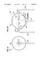
- FIG. 1Aillustrates an end view of a single axis tilt switch according to one embodiment of the invention
- FIG. 1Billustrates a side view of the single axis tilt switch of FIG. 1A
- FIG. 2illustrates a single axis tilt switch array according to another embodiment of the present invention
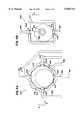
- FIG. 3Aillustrates a cross-section through a two axis tilt switch array according to another embodiment of the invention
- FIG. 3Billustrates an orthogonal view through the tilt switch array of FIG. 3A, as viewed through section 3B--3B;
- FIG. 4Aillustrates a cross-section through a two axis tilt switch array according to another embodiment of the invention
- FIG. 4Billustrates an orthogonal view through the tilt switch array of FIG. 4A, as viewed through section 4B--4B;
- FIG. 5illustrates another multi-axis tilt switch array according to another embodiment of the present invention
- FIG. 6illustrates a schematic cross section through the multi-axis tilt switch array of FIG. 5;
- FIG. 7Aillustrates an embodiment of an inner housing for a three axis tilt switch array in unfolded form
- FIG. 7Billustrates the inner housing of FIG. 7B in folded form
- FIG. 8illustrates the geometry of a ring and an electrode of a tilt switch gap.
- a single tilt switch unitincludes two or more tilt switch gaps, each of which can be closed by a metal ball, or other conducting element, free to move within the device.
- the tilt switch gapsare arranged along orthogonal axes, so that the orientation of these orthogonal axes relative to a downwards position may be measured.
- the present inventionhas application in small electronic devices in which an up/down orientation is to be measured. Examples of such electronic devices include radio transceivers, pagers, devices for locating buried electrical utilities and also electronic animal collars, as taught in U.S. Pat. No. 5,794,569.
- One advantage provided by the inventionconcerns the degree of control over the cone angle over which the tilt switch provides an "up" signal.
- FIGS. 1A and 1Billustrate one particular embodiment for the invention for detecting the orientation of a tilt switch array, generally indicated as 100, relative to an upward position direction.
- FIG. 1Aillustrates an end view of such a tilt switch array 100 and
- FIG. 1Billustrates a cross section through the tilt switch array 100.
- the tilt switch array 100includes two centered electrodes 102 and 104 that are diametrically opposed and lying along a single axis of the tilt switch 100.
- the electrodes 102 and 104are connected to respective external leads 106 and 108.
- the electrodes 102 and 104are enclosed within a housing 110 with respective insulating seals 112 and 114 to allow the electrodes 102 and 104 to pass through from inside the housing.
- a conducting ball 116is disposed within the housing 110 and is free to move within the housing 110 under external forces, as may be imparted to the ball 116 by gravity or acceleration due to motion.
- the outer surface of the housing 110is connected to a housing electrode 118.
- the housing 110is electrically conducting, so that there is an electrically conductive path from the housing electrode 118 to, for example, the second lead 108 through the housing 110, the ball 116, and the second electrode 104, when the ball 116 simultaneously contacts the inner surface of the housing 110 and the electrode 104, as illustrated.
- the housingis shaped so that those portions of the housing 110 surrounding the electrodes 102 and 104 form an angle, in this case 45°, relative to the axis lying between the electrodes 102 and 104.
- the housing 110includes a frustrated conical portion 120 surrounding the first electrode 102, and a second frustrated conical section 122 surrounding the second electrode 104.
- the ball 116contacts the second electrode 104 and the right portion 122 of the housing 110 when the electrode 104 points in an upward direction or points within a cone no more than 45° away from an upward direction.
- the second electrode 104is defined to point in the direction A, as shown.
- the second tilt switch between the housing lead 118 and the second lead 108is closed when the second electrode 104 is pointing within ⁇ 45° of an upward direction.
- the first tilt switch between the first lead 106 and the housing lead 118is closed when the ball 116 simultaneously contacts the first portion 120 of the housing 110 and the first electrode 102.
- the switch between the first lead and the housing lead 118is closed when the first electrode 102 points within ⁇ 45° of an upward direction.
- the first electrode 102is defined to point in the direction labeled "B.”
- the tilt switch array 200includes a housing 210 with first and second leads 206 and 208 and a housing lead 218 for attachment to an external circuit.
- the housing 210has first and second conical portions 220 and 222 around respective first and second electrodes 202 and 204.
- a ball 216is contained within the housing 210 and is free to move around therein, to form contacts between the housing 210 and either of the electrodes 202 and 204.
- the tilt switch array 200is similar to that illustrated in FIG. 1, except the electrodes 202 and 204 have round heads.
- Each electrode 202 and 204may be a semi-tubular rivet with respective leads 206 and 208 contacted inside the respective tubes. Insulating bushings 212 and 214 electrically insulate the housing 210 from the electrodes 202 and 204.
- Both of the single axis tilt switch arrays 100 and 200may include gas-tight sealed housings 110 and 210 where the housing is filled with an inert gas in order to prevent corrosion of the electrically conducting surfaces within the housings 110 and 210.
- the inner surface of the housing 110 and 210may be plated with a highly conducting metal, for example, gold or copper.
- the electrodes 102 and 104, and 202 and 204, and the electrically conducting balls 116 and 216may also be coated with a highly conducting metal such as gold or copper.
- angle of the frustrated conical sections of the housingsmay be chosen to be either larger or smaller than 45° in order to close the tilt switch when it is aligned within a larger or smaller angle relative to the upwards direction,
- the single axis tilt switch arraysmay be modified to accept a second pair of electrodes disposed along an axis orthogonal to the axis between the first pair of electrodes so that the tilt switch array may be used for detecting orientation along two different axes relative to an upward direction.
- a third pair of electrodesmay be provided along an axis mutually orthogonal to the first two electrode axes in order to permit the detection of the orientation of the tilt switch array along three directions.
- FIGS. 3A and 3Billustrate one particular embodiment of the invention that permits the detection of the orientation of two orthogonal axes relative to an upward direction.
- the tilt switch array 300includes an insulated housing 310 that has two pairs of mutually orthogonally arranged electrodes therein.
- the first pair of electrodes 302 and 304are disposed along the x-axis, and the second pair of electrodes 306 and 308 are disposed along the z-axis, orthogonal to the x-axis.
- Each electrode 302, 304, 306, and 308has an associated lead extending outwardly from the housing 310 for connection to an external circuit.
- Surrounding each electrode 302, 304, 306, and 308is a respective metallic ring 312, 314, 316, and 318.
- Each ring 312, 314, 316, and 318has an associated lead 332, 334, 336, and 338 extending through the housing 310 for connection to the external circuit.
- the external circuitpermits the user to determine which particular tilt switch, i.e. electrode/ring combination in the tilt switch array, is closed by the ball 320.
- each ring relative to its respective electrodeis chosen so that the tilt switch array 300 can detect when an electrode is directed to within ⁇ 45° of an upward direction.
- the ball 320rests on the electrode 306 and its associated ring 316, thus closing the electrical gap therebetween. If the tilt switch array 300 is tilted so that the z-axis is directed at more than a selected angle, ⁇ s , then the ball 320 falls out from the gap between the electrode 306 and ring 316. The ball 320 may then find another stable position in a gap between another electrode 302, 304, or 308 and its associated ring 312, 314 and 318 that points to within ⁇ s of an upward direction. In certain applications, ⁇ s may be selected to be 45°.
- this embodimentmay be adapted for detection of orientation along three axes, with the addition of a third pair of electrodes oriented orthogonally to the first two pairs of electrodes, and with concomitant rings surrounding the electrodes.
- FIGS. 4A and 4BAnother particular embodiment of a two-axis tilt switch array 400 is illustrated in FIGS. 4A and 4B.
- an insulated housing 410has disposed therein four electrodes 402, 404, 406, and 408, in pairs directed along orthogonal axes x and z.
- Each electrode 402, 404, 406, and 408has an associated lead 422, 424, 246, and 428 for connection to an external circuit for determining the orientation of the tilt switch array 400.
- a conducting liner 412is positioned within the housing 410, the liner 412 substantially covering the inner surface of the housing 410, apart from those portions immediately surrounding the electrodes 402, 404, 406, and 408.
- the lining 412is electrically isolated from each of the electrodes 402, 404, 406, and 408 by gaps therebetween.
- the walls of the housing 410form frustrated conical portions surrounding each of the electrodes 402, 404, 406, and 408 in a manner similar to that shown in FIGS. 1A and 2.
- the ball 420is free to move within the housing 410, and forms an electrical contact between the lining 412 and any electrode 402, 404, 406 or 408 that is pointing in a direction within ⁇ 45° of an upward direction.
- the orientation of two axes of the tilt switch array 400namely the x and z-axes, relative to an upward direction may be determined in response to which of the tilt switches formed by the electrodes 402, 404, 406, and 408 and the lining 412 is closed by the ball 420.
- FIG. 5illustrates one particular embodiment of the invention for detecting orientation of the tilt switch array 500 relative to two orthogonal axes.
- the tilt switch array 500detects orientation of the x- and z-axes relative to the upward direction.
- FIG. 5illustrates an exploded view of the tilt switch array 500.
- the housing 502 and lid 504enclose all the components, other than electrical connections (not shown).
- Inside the housing 502is an inner assembly 506.
- the inner assembly 506has apertures 508 on opposing walls 510. Plates 512a-512d are inserted between the opposing walls 510 and the housing 502. Each plate 512a-512d has a raised portion 514 in the center, raised in the direction of the conducting ball 516 which is centrally located but free to move within the inner assembly 506.
- the tilt switch array 500operates in the following manner, which is described with reference to FIG. 6, a schematic cross-section in the x-z plane of the tilt switch array 500.
- the plates 512a-512dare electrically isolated from each other, and from the inner assembly 506, which acts as a common.
- the ball 516falls to the lowest point within the inner assembly 506 under the pull of gravity. Over a wide range of angles, this position is reached when the conducting ball 516 rests against the raised portion 514 and the edge of the aperture 508.
- the conducting ball 516bridges the gap between the raised portion 514 and the edge of the aperture 508, forming an electrically conducting path therebetween.
- Each of the plates 512a-512dis connected to a controller 518, as is the inner assembly 506.
- the controller 518detects which of the plates 512a-512d is in electrical contact with the inner assembly 506, then the orientation of the tilt switch array 500 relative to a downward direction can be obtained.
- the controllerdetermines that the array's +z axis is pointing upwards.
- Reorientation of the tilt switch array 500 so that the conducting ball 516 bridges the gap between the assembly 506 and one of the other plates 512a, 512b, 512dis detected by the controller 518 when another plate 512a, 512b or 512d is connected to the inner assembly 506 by the conducting ball 516.
- the embodiment illustrated in FIG. 5is for illustrative purposes only and does not limit the invention.
- the plates 512a-512dmay be replaced by other components that provide contact for the ball 516, that is centrally located within the aperture 508 of the inner assembly 506.
- the inner assembly 506may simply be a number of separate conducting rings with their apertures positioned around the respective raised portions 514.
- the conducting ball 516may be formed of metal, or of a conducting rubber.
- the conducting ball 516may also be a ball of mercury, particularly if the tilt switch array 500 is built sufficiently small that the surface tension of the mercury is sufficient to maintain an overall ball-like shape.
- the tilt switch array 500need not detect the orientation of two axes, but may be used simply to detect the orientation of one axis, for example, the orientation of the z-axis. This may be achieved by removing the +x and -x plates 512a and 512b, or by simply ignoring the information generated by the +x and -x plates. It will further be appreciated that the inner assembly 506 may be provided with opposing walls on all six sides, each with an aperture 508 therein. Additionally, the tilt 30 switch array 500 may be provided with three pairs of plates 512 orthogonally arranged. Such an embodiment permits the detection of which axis out of all three axes is closest to being vertical.
- the inner assemblymay be formed from a single, stamped metal sheet which is folded into shape.
- FIG. 7Aillustrates a single stamping 700 which may be folded at joints 702 to form the inner housing 700 shown in FIG. 7B.
- the inner housingmay be essentially cubic, as illustrated.
- the inner assembly 700is illustrated having six apertures 704, one aperture 704 in each side wall, providing for a tilt switch array operational with respect to three orthogonal axes.
- an important parameter for the user of the tilt switch array 500is the range of angle through which the tilt switch array 500 may be tilted before the ball 516 leaves the gap between the raised portion 514 and the side of the aperture 508, thus opening the circuit.
- FIG. 8schematically illustrates a raised portion 814 and one edge of a ring, or aperture 808, with a ball 816 resting therebetween.
- the ball 816is assumed to be spherical, and its center of mass at the center of the sphere.
- FIG. 8illustrates a cross-section taken through the plane described by the center of the ball 816 and the point of contact 822 and 824 on the electrode 814 and the ring 808, respectively.
- the dashed lines 826 and 828indicate different vertical axes.
- the first vertical axis 826illustrates the situation where the ring 808 is horizontally placed relative the electrode 814.
- a vertical line from the ball's center of gravity, at X 820intersects the line L, length a, lying between the contacting points 822 and 824. Therefore, the ball 816 sits in the gap between the electrode 814 and the ring 808.
- the angle, ⁇ cthrough which the tilt switch array can be rotated before a he ball 816 falls out from the ring can be shown to be given by ##EQU1##
- the designer of the tilt switch arraymay select the angular tilt range over which the tilt switch array indicates that a particular axis of the tilt switch array is pointing downwards.
- the critical angle ⁇ cmay be set at 45°. Therefore, as the tilt switch array 600 is rotated, the ball 516 escapes from one aperture 508 and is immediately trapped by an adjacent aperture 508. Therefore, as the array 600 is rotated, there is very little "dead time" when the ball 516 is not trapped in one of the gaps of a tilt switch.
- the critical anglemay be set to be small, for example, ranging from 5° to 10°. In this case, there is a wide range of orientation angles over which none of the tilt switches in the tilt switch array are closed.
- the point of the electrode that contacts the ballmay not lie in the plane of the ring. It will be appreciated that, in such a case, the separation distance between the electrode and its associated ring/conducting perimeter and the diameter of the ball may be selected to provide a predetermined critical angle.
- the tilt switch arrays disclosed hereinmay be used as jitter switches for detecting motion in addition to detecting orientation.
- the conducting ballmakes interrupted contact with one or more of the tilt switches in the array due to its motion.
- the tilt switch arrayis used in an electronic unit that is attached to a pet animal, such as a dog, then the motion of the dog as it walks or runs may cause the conducting ball within the tilt switch array to make only intermittent contact with one or more of the tilt switches within the array. The detection of such intermittent operation may be used as an indicator that the animal is in motion.
- Jitter operation of a switchmay be slowed by providing a damping fluid within the tilt switch array. Viscous forces act on the conducting ball to slow the movement of the ball within the housing under small applied forces, and so the response time of the ball may be increased. Accordingly, the addition of damping fluid may increase the amount of motion required to initiate jitter-type operation.
Landscapes
- Switches Operated By Changes In Physical Conditions (AREA)
Abstract
Description
Claims (17)
Priority Applications (1)
| Application Number | Priority Date | Filing Date | Title |
|---|---|---|---|
| US08/943,780US5955713A (en) | 1997-10-03 | 1997-10-03 | Tilt switch array for electronic orientation detection |
Applications Claiming Priority (1)
| Application Number | Priority Date | Filing Date | Title |
|---|---|---|---|
| US08/943,780US5955713A (en) | 1997-10-03 | 1997-10-03 | Tilt switch array for electronic orientation detection |
Publications (1)
| Publication Number | Publication Date |
|---|---|
| US5955713Atrue US5955713A (en) | 1999-09-21 |
Family
ID=25480245
Family Applications (1)
| Application Number | Title | Priority Date | Filing Date |
|---|---|---|---|
| US08/943,780Expired - Fee RelatedUS5955713A (en) | 1997-10-03 | 1997-10-03 | Tilt switch array for electronic orientation detection |
Country Status (1)
| Country | Link |
|---|---|
| US (1) | US5955713A (en) |
Cited By (50)
| Publication number | Priority date | Publication date | Assignee | Title |
|---|---|---|---|---|
| US6115929A (en)* | 1997-07-02 | 2000-09-12 | Casio Computer Co., Ltd. | Tilt detecting device |
| US6236001B1 (en)* | 1999-08-03 | 2001-05-22 | Wayne W. Shymko | Scoop with weigh scale |
| US6247239B1 (en)* | 1997-05-16 | 2001-06-19 | Asahi Kogaku Kogyo Kabushiki Kaisha | Clinometric sensor |
| US6375572B1 (en) | 1999-10-04 | 2002-04-23 | Nintendo Co., Ltd. | Portable game apparatus with acceleration sensor and information storage medium storing a game progam |
| USD470823S1 (en) | 2002-04-18 | 2003-02-25 | Ufer Robert P | Acceleration switch |
| USD474159S1 (en) | 2002-01-25 | 2003-05-06 | Robert P. Ufer | Acceleration switch |
| US6568094B2 (en)* | 2001-01-12 | 2003-05-27 | Chyi-Yiing Wu | Compact optical calibrating apparatus for multiple orientations |
| US20030196878A1 (en)* | 2002-02-07 | 2003-10-23 | Alps Electric Co., Ltd. | Tilt detector |
| US20030204962A1 (en)* | 2000-04-14 | 2003-11-06 | Mangerson Mark M. | Orientation sensor |
| US20040029640A1 (en)* | 1999-10-04 | 2004-02-12 | Nintendo Co., Ltd. | Game system and game information storage medium used for same |
| US20050047130A1 (en)* | 2003-08-29 | 2005-03-03 | Waters Michael A. | Picture light apparatus and method |
| US20050091862A1 (en)* | 2003-10-29 | 2005-05-05 | Hiram Diaz | Inclination angle reader and method for using same |
| US6908386B2 (en) | 2002-05-17 | 2005-06-21 | Nintendo Co., Ltd. | Game device changing sound and an image in accordance with a tilt operation |
| US20050195091A1 (en)* | 2004-03-08 | 2005-09-08 | Nuvo Holdings, Llc | Tilt Sensor Apparatus and Method Therefor |
| US20050195081A1 (en)* | 2004-03-08 | 2005-09-08 | Studnicki Adam A. | Asset tag with event detection capabilities |
| US20060065114A1 (en)* | 2004-09-27 | 2006-03-30 | Vincent Edwards | Switch |
| US20070012552A1 (en)* | 2005-07-14 | 2007-01-18 | Tien-Ming Chou | Jerk-initiated switch |
| US20070214669A1 (en)* | 2006-03-20 | 2007-09-20 | Van Luchene Andrew S | Automated Leveling Apparatus |
| US20080140339A1 (en)* | 2006-12-08 | 2008-06-12 | Terry Michele Ciccaglione | Six face, multi-event, orientation sensor |
| US20080135384A1 (en)* | 2006-03-20 | 2008-06-12 | Leviathan Entertainment | Automated Leveling Apparatus |
| GB2420109B (en)* | 2004-09-27 | 2008-08-20 | Autocraft Engineering 1991 Ltd | Switch |
| US20080228432A1 (en)* | 2007-03-14 | 2008-09-18 | Computime, Ltd. | Electrical Device with a Selected Orientation for Operation |
| US20080301956A1 (en)* | 2007-06-07 | 2008-12-11 | Wen-Jan Hong | Inclination-detecting device |
| US20090294261A1 (en)* | 2008-05-28 | 2009-12-03 | Pociejewski Peter J | Automotive acceleration alarm to inform the driver of when to limit excessive acceleration to decrease gasoline consumption |
| US20100072098A1 (en)* | 2008-09-25 | 2010-03-25 | Babaco Alarm Systems, Inc. | Shred box with alarm system |
| US7716008B2 (en) | 2007-01-19 | 2010-05-11 | Nintendo Co., Ltd. | Acceleration data processing program, and storage medium, and acceleration data processing apparatus for use with the same |
| US20100176961A1 (en)* | 2009-01-13 | 2010-07-15 | Nelson Donald M | Cargo Loading Trailer |
| US7774155B2 (en) | 2006-03-10 | 2010-08-10 | Nintendo Co., Ltd. | Accelerometer-based controller |
| US7927216B2 (en) | 2005-09-15 | 2011-04-19 | Nintendo Co., Ltd. | Video game system with wireless modular handheld controller |
| US8089458B2 (en) | 2000-02-22 | 2012-01-03 | Creative Kingdoms, Llc | Toy devices and methods for providing an interactive play experience |
| US8157651B2 (en) | 2005-09-12 | 2012-04-17 | Nintendo Co., Ltd. | Information processing program |
| US8226493B2 (en) | 2002-08-01 | 2012-07-24 | Creative Kingdoms, Llc | Interactive play devices for water play attractions |
| US8267786B2 (en) | 2005-08-24 | 2012-09-18 | Nintendo Co., Ltd. | Game controller and game system |
| US8308563B2 (en) | 2005-08-30 | 2012-11-13 | Nintendo Co., Ltd. | Game system and storage medium having game program stored thereon |
| US8313379B2 (en) | 2005-08-22 | 2012-11-20 | Nintendo Co., Ltd. | Video game system with wireless modular handheld controller |
| US8409003B2 (en) | 2005-08-24 | 2013-04-02 | Nintendo Co., Ltd. | Game controller and game system |
| US8475275B2 (en) | 2000-02-22 | 2013-07-02 | Creative Kingdoms, Llc | Interactive toys and games connecting physical and virtual play environments |
| US8608535B2 (en) | 2002-04-05 | 2013-12-17 | Mq Gaming, Llc | Systems and methods for providing an interactive game |
| KR101352435B1 (en) | 2012-09-07 | 2014-01-20 | 주식회사 동부하이텍 | A semiconductor device and a method of manufactur ing the same |
| KR101352434B1 (en)* | 2012-09-07 | 2014-01-22 | 주식회사 동부하이텍 | A semiconductor device and a method of manufactur ing the same |
| US8671582B2 (en)* | 2012-08-01 | 2014-03-18 | Shockwatch, Inc. | Tilt indicator |
| US8702515B2 (en) | 2002-04-05 | 2014-04-22 | Mq Gaming, Llc | Multi-platform gaming system using RFID-tagged toys |
| US8708821B2 (en) | 2000-02-22 | 2014-04-29 | Creative Kingdoms, Llc | Systems and methods for providing interactive game play |
| US8753165B2 (en) | 2000-10-20 | 2014-06-17 | Mq Gaming, Llc | Wireless toy systems and methods for interactive entertainment |
| US8758136B2 (en) | 1999-02-26 | 2014-06-24 | Mq Gaming, Llc | Multi-platform gaming systems and methods |
| US20140187681A1 (en)* | 2012-12-31 | 2014-07-03 | Virginia Tech Intellectual Properties, Inc. | Jellyfish-inspired tilt sensor and artificial mesoglea |
| US9011248B2 (en) | 2005-08-22 | 2015-04-21 | Nintendo Co., Ltd. | Game operating device |
| WO2015157860A1 (en)* | 2014-04-16 | 2015-10-22 | Hendrie William S | Door alarm |
| US9446319B2 (en) | 2003-03-25 | 2016-09-20 | Mq Gaming, Llc | Interactive gaming toy |
| US12044548B2 (en) | 2020-01-14 | 2024-07-23 | Shock Watch, Inc. | Tilt indicator |
Citations (12)
| Publication number | Priority date | Publication date | Assignee | Title |
|---|---|---|---|---|
| US2450780A (en)* | 1946-02-15 | 1948-10-05 | Durakool Inc | Electrode mounting means for mercury switches and relays |
| US3729602A (en)* | 1971-10-27 | 1973-04-24 | R Myers | Tilt responsive switch with ball contact actuating structure |
| US3812308A (en)* | 1972-08-23 | 1974-05-21 | Technar Inc | Ball actuated inertia switch |
| US3927286A (en)* | 1972-06-13 | 1975-12-16 | Foehl Artur | Inertia type switch having bridging ball contactor and plural, concentric conductive ring array |
| US4090040A (en)* | 1976-05-31 | 1978-05-16 | Ole Berland | Hearing aid with acoustical frequency response modification |
| US4135067A (en)* | 1976-03-30 | 1979-01-16 | Fifth Dimension, Inc. | Tilt switch and holder |
| US4467154A (en)* | 1983-05-04 | 1984-08-21 | U. S. Plastics Corporation | Gravity switch and method of making same |
| US4513183A (en)* | 1983-05-04 | 1985-04-23 | U.S. Plastics Corporation | Gravity switch |
| US4618746A (en)* | 1984-06-05 | 1986-10-21 | Seb S.A. | Ball actuated position sensitive switch |
| US4668846A (en)* | 1985-12-31 | 1987-05-26 | Klumpp Henry B | Gravity sensing switch for detecting inclination |
| US5006676A (en)* | 1989-12-26 | 1991-04-09 | Motorola Inc. | Movement sensor switch |
| US5630280A (en)* | 1995-05-01 | 1997-05-20 | The Fredericks Company | Dual axis electrolytic tilt sensor |
- 1997
- 1997-10-03USUS08/943,780patent/US5955713A/ennot_activeExpired - Fee Related
Patent Citations (12)
| Publication number | Priority date | Publication date | Assignee | Title |
|---|---|---|---|---|
| US2450780A (en)* | 1946-02-15 | 1948-10-05 | Durakool Inc | Electrode mounting means for mercury switches and relays |
| US3729602A (en)* | 1971-10-27 | 1973-04-24 | R Myers | Tilt responsive switch with ball contact actuating structure |
| US3927286A (en)* | 1972-06-13 | 1975-12-16 | Foehl Artur | Inertia type switch having bridging ball contactor and plural, concentric conductive ring array |
| US3812308A (en)* | 1972-08-23 | 1974-05-21 | Technar Inc | Ball actuated inertia switch |
| US4135067A (en)* | 1976-03-30 | 1979-01-16 | Fifth Dimension, Inc. | Tilt switch and holder |
| US4090040A (en)* | 1976-05-31 | 1978-05-16 | Ole Berland | Hearing aid with acoustical frequency response modification |
| US4467154A (en)* | 1983-05-04 | 1984-08-21 | U. S. Plastics Corporation | Gravity switch and method of making same |
| US4513183A (en)* | 1983-05-04 | 1985-04-23 | U.S. Plastics Corporation | Gravity switch |
| US4618746A (en)* | 1984-06-05 | 1986-10-21 | Seb S.A. | Ball actuated position sensitive switch |
| US4668846A (en)* | 1985-12-31 | 1987-05-26 | Klumpp Henry B | Gravity sensing switch for detecting inclination |
| US5006676A (en)* | 1989-12-26 | 1991-04-09 | Motorola Inc. | Movement sensor switch |
| US5630280A (en)* | 1995-05-01 | 1997-05-20 | The Fredericks Company | Dual axis electrolytic tilt sensor |
Cited By (155)
| Publication number | Priority date | Publication date | Assignee | Title |
|---|---|---|---|---|
| US6247239B1 (en)* | 1997-05-16 | 2001-06-19 | Asahi Kogaku Kogyo Kabushiki Kaisha | Clinometric sensor |
| US6341428B1 (en)* | 1997-07-02 | 2002-01-29 | Casio Computer Co., Ltd. | Tilt detecting device |
| US6115929A (en)* | 1997-07-02 | 2000-09-12 | Casio Computer Co., Ltd. | Tilt detecting device |
| US9861887B1 (en) | 1999-02-26 | 2018-01-09 | Mq Gaming, Llc | Multi-platform gaming systems and methods |
| US8758136B2 (en) | 1999-02-26 | 2014-06-24 | Mq Gaming, Llc | Multi-platform gaming systems and methods |
| US8888576B2 (en) | 1999-02-26 | 2014-11-18 | Mq Gaming, Llc | Multi-media interactive play system |
| US9186585B2 (en) | 1999-02-26 | 2015-11-17 | Mq Gaming, Llc | Multi-platform gaming systems and methods |
| US10300374B2 (en) | 1999-02-26 | 2019-05-28 | Mq Gaming, Llc | Multi-platform gaming systems and methods |
| US9468854B2 (en) | 1999-02-26 | 2016-10-18 | Mq Gaming, Llc | Multi-platform gaming systems and methods |
| US9731194B2 (en) | 1999-02-26 | 2017-08-15 | Mq Gaming, Llc | Multi-platform gaming systems and methods |
| US6236001B1 (en)* | 1999-08-03 | 2001-05-22 | Wayne W. Shymko | Scoop with weigh scale |
| US7601066B1 (en) | 1999-10-04 | 2009-10-13 | Nintendo Co., Ltd. | Game system and game information storage medium used for same |
| US6641482B2 (en) | 1999-10-04 | 2003-11-04 | Nintendo Co., Ltd. | Portable game apparatus with acceleration sensor and information storage medium storing a game program |
| US8562402B2 (en) | 1999-10-04 | 2013-10-22 | Nintendo Co., Ltd. | Game system and game information storage medium used for same |
| US10046231B2 (en) | 1999-10-04 | 2018-08-14 | Nintendo Co., Ltd. | Game system and game information storage medium used for same |
| US6375572B1 (en) | 1999-10-04 | 2002-04-23 | Nintendo Co., Ltd. | Portable game apparatus with acceleration sensor and information storage medium storing a game progam |
| US20040029640A1 (en)* | 1999-10-04 | 2004-02-12 | Nintendo Co., Ltd. | Game system and game information storage medium used for same |
| US20090325698A1 (en)* | 1999-10-04 | 2009-12-31 | Nintendo Co., Ltd. | Game system and game information storage medium used for same |
| US9138645B2 (en) | 1999-10-04 | 2015-09-22 | Nintendo Co., Ltd. | Game system and game information storage medium used for same |
| US9205332B2 (en) | 1999-10-04 | 2015-12-08 | Nintendo Co., Ltd. | Game system and game information storage medium used for same |
| US9579565B2 (en) | 1999-10-04 | 2017-02-28 | Nintendo Co., Ltd. | Game system and game information storage medium used for same |
| US9205331B2 (en) | 1999-10-04 | 2015-12-08 | Nintendo Co., Ltd. | Mobile wireless handset and system including mobile wireless handset |
| US20070178974A1 (en)* | 1999-10-04 | 2007-08-02 | Nintendo Co., Ltd. | Game system and game information storage medium used for same |
| US7223173B2 (en) | 1999-10-04 | 2007-05-29 | Nintendo Co., Ltd. | Game system and game information storage medium used for same |
| US8708821B2 (en) | 2000-02-22 | 2014-04-29 | Creative Kingdoms, Llc | Systems and methods for providing interactive game play |
| US8531050B2 (en) | 2000-02-22 | 2013-09-10 | Creative Kingdoms, Llc | Wirelessly powered gaming device |
| US8164567B1 (en) | 2000-02-22 | 2012-04-24 | Creative Kingdoms, Llc | Motion-sensitive game controller with optional display screen |
| US8184097B1 (en) | 2000-02-22 | 2012-05-22 | Creative Kingdoms, Llc | Interactive gaming system and method using motion-sensitive input device |
| US9579568B2 (en) | 2000-02-22 | 2017-02-28 | Mq Gaming, Llc | Dual-range wireless interactive entertainment device |
| US9713766B2 (en) | 2000-02-22 | 2017-07-25 | Mq Gaming, Llc | Dual-range wireless interactive entertainment device |
| US8089458B2 (en) | 2000-02-22 | 2012-01-03 | Creative Kingdoms, Llc | Toy devices and methods for providing an interactive play experience |
| US9149717B2 (en) | 2000-02-22 | 2015-10-06 | Mq Gaming, Llc | Dual-range wireless interactive entertainment device |
| US8368648B2 (en) | 2000-02-22 | 2013-02-05 | Creative Kingdoms, Llc | Portable interactive toy with radio frequency tracking device |
| US8475275B2 (en) | 2000-02-22 | 2013-07-02 | Creative Kingdoms, Llc | Interactive toys and games connecting physical and virtual play environments |
| US8915785B2 (en) | 2000-02-22 | 2014-12-23 | Creative Kingdoms, Llc | Interactive entertainment system |
| US8491389B2 (en) | 2000-02-22 | 2013-07-23 | Creative Kingdoms, Llc. | Motion-sensitive input device and interactive gaming system |
| US8814688B2 (en) | 2000-02-22 | 2014-08-26 | Creative Kingdoms, Llc | Customizable toy for playing a wireless interactive game having both physical and virtual elements |
| US8790180B2 (en) | 2000-02-22 | 2014-07-29 | Creative Kingdoms, Llc | Interactive game and associated wireless toy |
| US10307671B2 (en) | 2000-02-22 | 2019-06-04 | Mq Gaming, Llc | Interactive entertainment system |
| US8169406B2 (en) | 2000-02-22 | 2012-05-01 | Creative Kingdoms, Llc | Motion-sensitive wand controller for a game |
| US9474962B2 (en) | 2000-02-22 | 2016-10-25 | Mq Gaming, Llc | Interactive entertainment system |
| US9814973B2 (en) | 2000-02-22 | 2017-11-14 | Mq Gaming, Llc | Interactive entertainment system |
| US10188953B2 (en) | 2000-02-22 | 2019-01-29 | Mq Gaming, Llc | Dual-range wireless interactive entertainment device |
| US8686579B2 (en) | 2000-02-22 | 2014-04-01 | Creative Kingdoms, Llc | Dual-range wireless controller |
| US6732440B2 (en)* | 2000-04-14 | 2004-05-11 | Gateway, Inc. | Orientation sensor |
| US20030204962A1 (en)* | 2000-04-14 | 2003-11-06 | Mangerson Mark M. | Orientation sensor |
| US9931578B2 (en) | 2000-10-20 | 2018-04-03 | Mq Gaming, Llc | Toy incorporating RFID tag |
| US8753165B2 (en) | 2000-10-20 | 2014-06-17 | Mq Gaming, Llc | Wireless toy systems and methods for interactive entertainment |
| US10307683B2 (en) | 2000-10-20 | 2019-06-04 | Mq Gaming, Llc | Toy incorporating RFID tag |
| US8961260B2 (en) | 2000-10-20 | 2015-02-24 | Mq Gaming, Llc | Toy incorporating RFID tracking device |
| US9480929B2 (en) | 2000-10-20 | 2016-11-01 | Mq Gaming, Llc | Toy incorporating RFID tag |
| US9320976B2 (en) | 2000-10-20 | 2016-04-26 | Mq Gaming, Llc | Wireless toy systems and methods for interactive entertainment |
| US6568094B2 (en)* | 2001-01-12 | 2003-05-27 | Chyi-Yiing Wu | Compact optical calibrating apparatus for multiple orientations |
| US8711094B2 (en) | 2001-02-22 | 2014-04-29 | Creative Kingdoms, Llc | Portable gaming device and gaming system combining both physical and virtual play elements |
| US8913011B2 (en) | 2001-02-22 | 2014-12-16 | Creative Kingdoms, Llc | Wireless entertainment device, system, and method |
| US10179283B2 (en) | 2001-02-22 | 2019-01-15 | Mq Gaming, Llc | Wireless entertainment device, system, and method |
| US8248367B1 (en) | 2001-02-22 | 2012-08-21 | Creative Kingdoms, Llc | Wireless gaming system combining both physical and virtual play elements |
| US9737797B2 (en) | 2001-02-22 | 2017-08-22 | Mq Gaming, Llc | Wireless entertainment device, system, and method |
| US9162148B2 (en) | 2001-02-22 | 2015-10-20 | Mq Gaming, Llc | Wireless entertainment device, system, and method |
| US9393491B2 (en) | 2001-02-22 | 2016-07-19 | Mq Gaming, Llc | Wireless entertainment device, system, and method |
| US10758818B2 (en) | 2001-02-22 | 2020-09-01 | Mq Gaming, Llc | Wireless entertainment device, system, and method |
| US8384668B2 (en) | 2001-02-22 | 2013-02-26 | Creative Kingdoms, Llc | Portable gaming device and gaming system combining both physical and virtual play elements |
| USD474159S1 (en) | 2002-01-25 | 2003-05-06 | Robert P. Ufer | Acceleration switch |
| US6706978B2 (en) | 2002-02-07 | 2004-03-16 | Alps Electric Co., Ltd. | Tilt detector |
| US20030196878A1 (en)* | 2002-02-07 | 2003-10-23 | Alps Electric Co., Ltd. | Tilt detector |
| US10478719B2 (en) | 2002-04-05 | 2019-11-19 | Mq Gaming, Llc | Methods and systems for providing personalized interactive entertainment |
| US9272206B2 (en) | 2002-04-05 | 2016-03-01 | Mq Gaming, Llc | System and method for playing an interactive game |
| US11278796B2 (en) | 2002-04-05 | 2022-03-22 | Mq Gaming, Llc | Methods and systems for providing personalized interactive entertainment |
| US8608535B2 (en) | 2002-04-05 | 2013-12-17 | Mq Gaming, Llc | Systems and methods for providing an interactive game |
| US10507387B2 (en) | 2002-04-05 | 2019-12-17 | Mq Gaming, Llc | System and method for playing an interactive game |
| US9463380B2 (en) | 2002-04-05 | 2016-10-11 | Mq Gaming, Llc | System and method for playing an interactive game |
| US10010790B2 (en) | 2002-04-05 | 2018-07-03 | Mq Gaming, Llc | System and method for playing an interactive game |
| US9616334B2 (en) | 2002-04-05 | 2017-04-11 | Mq Gaming, Llc | Multi-platform gaming system using RFID-tagged toys |
| US8702515B2 (en) | 2002-04-05 | 2014-04-22 | Mq Gaming, Llc | Multi-platform gaming system using RFID-tagged toys |
| US8827810B2 (en) | 2002-04-05 | 2014-09-09 | Mq Gaming, Llc | Methods for providing interactive entertainment |
| USD470823S1 (en) | 2002-04-18 | 2003-02-25 | Ufer Robert P | Acceleration switch |
| US6908386B2 (en) | 2002-05-17 | 2005-06-21 | Nintendo Co., Ltd. | Game device changing sound and an image in accordance with a tilt operation |
| US8226493B2 (en) | 2002-08-01 | 2012-07-24 | Creative Kingdoms, Llc | Interactive play devices for water play attractions |
| US9993724B2 (en) | 2003-03-25 | 2018-06-12 | Mq Gaming, Llc | Interactive gaming toy |
| US10369463B2 (en) | 2003-03-25 | 2019-08-06 | Mq Gaming, Llc | Wireless interactive game having both physical and virtual elements |
| US10022624B2 (en) | 2003-03-25 | 2018-07-17 | Mq Gaming, Llc | Wireless interactive game having both physical and virtual elements |
| US10583357B2 (en) | 2003-03-25 | 2020-03-10 | Mq Gaming, Llc | Interactive gaming toy |
| US9707478B2 (en) | 2003-03-25 | 2017-07-18 | Mq Gaming, Llc | Motion-sensitive controller and associated gaming applications |
| US9039533B2 (en) | 2003-03-25 | 2015-05-26 | Creative Kingdoms, Llc | Wireless interactive game having both physical and virtual elements |
| US11052309B2 (en) | 2003-03-25 | 2021-07-06 | Mq Gaming, Llc | Wireless interactive game having both physical and virtual elements |
| US8373659B2 (en) | 2003-03-25 | 2013-02-12 | Creative Kingdoms, Llc | Wirelessly-powered toy for gaming |
| US9770652B2 (en) | 2003-03-25 | 2017-09-26 | Mq Gaming, Llc | Wireless interactive game having both physical and virtual elements |
| US9446319B2 (en) | 2003-03-25 | 2016-09-20 | Mq Gaming, Llc | Interactive gaming toy |
| US9393500B2 (en) | 2003-03-25 | 2016-07-19 | Mq Gaming, Llc | Wireless interactive game having both physical and virtual elements |
| US8961312B2 (en) | 2003-03-25 | 2015-02-24 | Creative Kingdoms, Llc | Motion-sensitive controller and associated gaming applications |
| US20050047130A1 (en)* | 2003-08-29 | 2005-03-03 | Waters Michael A. | Picture light apparatus and method |
| US7066619B2 (en)* | 2003-08-29 | 2006-06-27 | Waters Michael A | LED picture light apparatus and method |
| US7055255B2 (en) | 2003-10-29 | 2006-06-06 | Hiram Diaz | Inclination angle reader and method for using same |
| US20050091862A1 (en)* | 2003-10-29 | 2005-05-05 | Hiram Diaz | Inclination angle reader and method for using same |
| US20050195091A1 (en)* | 2004-03-08 | 2005-09-08 | Nuvo Holdings, Llc | Tilt Sensor Apparatus and Method Therefor |
| US20050195081A1 (en)* | 2004-03-08 | 2005-09-08 | Studnicki Adam A. | Asset tag with event detection capabilities |
| US7088258B2 (en)* | 2004-03-08 | 2006-08-08 | Nuvo Holdings, Llc | Tilt sensor apparatus and method therefor |
| US7598883B2 (en) | 2004-03-08 | 2009-10-06 | Sgs Technologies, L.L.C. | Tilt sensor apparatus and method therefor |
| US20070188338A1 (en)* | 2004-03-08 | 2007-08-16 | Nuvo Holdings, Llc | Tilt sensor apparatus and method therefor |
| US7190278B2 (en) | 2004-03-08 | 2007-03-13 | Nuvo Holdings, Llc | Asset tag with event detection capabilities |
| US7255037B2 (en)* | 2004-09-27 | 2007-08-14 | Vincent Edwards | Switch |
| US20060065114A1 (en)* | 2004-09-27 | 2006-03-30 | Vincent Edwards | Switch |
| GB2420109B (en)* | 2004-09-27 | 2008-08-20 | Autocraft Engineering 1991 Ltd | Switch |
| US9675878B2 (en) | 2004-09-29 | 2017-06-13 | Mq Gaming, Llc | System and method for playing a virtual game by sensing physical movements |
| US7230193B2 (en)* | 2005-07-14 | 2007-06-12 | Tien-Ming Chou | Jerk-initiated switch |
| US20070012552A1 (en)* | 2005-07-14 | 2007-01-18 | Tien-Ming Chou | Jerk-initiated switch |
| US10661183B2 (en) | 2005-08-22 | 2020-05-26 | Nintendo Co., Ltd. | Game operating device |
| US9700806B2 (en) | 2005-08-22 | 2017-07-11 | Nintendo Co., Ltd. | Game operating device |
| US9498728B2 (en) | 2005-08-22 | 2016-11-22 | Nintendo Co., Ltd. | Game operating device |
| US9011248B2 (en) | 2005-08-22 | 2015-04-21 | Nintendo Co., Ltd. | Game operating device |
| US8313379B2 (en) | 2005-08-22 | 2012-11-20 | Nintendo Co., Ltd. | Video game system with wireless modular handheld controller |
| US10238978B2 (en) | 2005-08-22 | 2019-03-26 | Nintendo Co., Ltd. | Game operating device |
| US10155170B2 (en) | 2005-08-22 | 2018-12-18 | Nintendo Co., Ltd. | Game operating device with holding portion detachably holding an electronic device |
| US9227138B2 (en) | 2005-08-24 | 2016-01-05 | Nintendo Co., Ltd. | Game controller and game system |
| US8409003B2 (en) | 2005-08-24 | 2013-04-02 | Nintendo Co., Ltd. | Game controller and game system |
| US8870655B2 (en) | 2005-08-24 | 2014-10-28 | Nintendo Co., Ltd. | Wireless game controllers |
| US9498709B2 (en) | 2005-08-24 | 2016-11-22 | Nintendo Co., Ltd. | Game controller and game system |
| US9044671B2 (en) | 2005-08-24 | 2015-06-02 | Nintendo Co., Ltd. | Game controller and game system |
| US10137365B2 (en) | 2005-08-24 | 2018-11-27 | Nintendo Co., Ltd. | Game controller and game system |
| US8267786B2 (en) | 2005-08-24 | 2012-09-18 | Nintendo Co., Ltd. | Game controller and game system |
| US8834271B2 (en) | 2005-08-24 | 2014-09-16 | Nintendo Co., Ltd. | Game controller and game system |
| US11027190B2 (en) | 2005-08-24 | 2021-06-08 | Nintendo Co., Ltd. | Game controller and game system |
| US8308563B2 (en) | 2005-08-30 | 2012-11-13 | Nintendo Co., Ltd. | Game system and storage medium having game program stored thereon |
| US8708824B2 (en) | 2005-09-12 | 2014-04-29 | Nintendo Co., Ltd. | Information processing program |
| US8157651B2 (en) | 2005-09-12 | 2012-04-17 | Nintendo Co., Ltd. | Information processing program |
| US8430753B2 (en) | 2005-09-15 | 2013-04-30 | Nintendo Co., Ltd. | Video game system with wireless modular handheld controller |
| US7927216B2 (en) | 2005-09-15 | 2011-04-19 | Nintendo Co., Ltd. | Video game system with wireless modular handheld controller |
| USRE45905E1 (en) | 2005-09-15 | 2016-03-01 | Nintendo Co., Ltd. | Video game system with wireless modular handheld controller |
| US7774155B2 (en) | 2006-03-10 | 2010-08-10 | Nintendo Co., Ltd. | Accelerometer-based controller |
| WO2007109680A3 (en)* | 2006-03-20 | 2008-05-15 | Leviathan Entertainment | Automated leveling apparatus |
| US20080135384A1 (en)* | 2006-03-20 | 2008-06-12 | Leviathan Entertainment | Automated Leveling Apparatus |
| US7568291B2 (en)* | 2006-03-20 | 2009-08-04 | Leviathan | Automated leveling apparatus |
| US20070214669A1 (en)* | 2006-03-20 | 2007-09-20 | Van Luchene Andrew S | Automated Leveling Apparatus |
| US20080140339A1 (en)* | 2006-12-08 | 2008-06-12 | Terry Michele Ciccaglione | Six face, multi-event, orientation sensor |
| US8035497B2 (en) | 2006-12-08 | 2011-10-11 | International Business Machines Corporation | Multi-face, multi-event, orientation sensor |
| US7880598B2 (en) | 2006-12-08 | 2011-02-01 | International Business Machines Corporation | Six face, multi-event, orientation sensor |
| US7716008B2 (en) | 2007-01-19 | 2010-05-11 | Nintendo Co., Ltd. | Acceleration data processing program, and storage medium, and acceleration data processing apparatus for use with the same |
| US7999789B2 (en)* | 2007-03-14 | 2011-08-16 | Computime, Ltd. | Electrical device with a selected orientation for operation |
| US20080228432A1 (en)* | 2007-03-14 | 2008-09-18 | Computime, Ltd. | Electrical Device with a Selected Orientation for Operation |
| US20080301956A1 (en)* | 2007-06-07 | 2008-12-11 | Wen-Jan Hong | Inclination-detecting device |
| US20090294261A1 (en)* | 2008-05-28 | 2009-12-03 | Pociejewski Peter J | Automotive acceleration alarm to inform the driver of when to limit excessive acceleration to decrease gasoline consumption |
| US20100072098A1 (en)* | 2008-09-25 | 2010-03-25 | Babaco Alarm Systems, Inc. | Shred box with alarm system |
| US9945753B2 (en)* | 2009-01-13 | 2018-04-17 | United Aeronautical Corp. | Cargo loading trailer |
| US20100176961A1 (en)* | 2009-01-13 | 2010-07-15 | Nelson Donald M | Cargo Loading Trailer |
| US8671582B2 (en)* | 2012-08-01 | 2014-03-18 | Shockwatch, Inc. | Tilt indicator |
| US9354055B2 (en) | 2012-08-01 | 2016-05-31 | Shockwatch, Inc. | Tilt indicator |
| KR101352435B1 (en) | 2012-09-07 | 2014-01-20 | 주식회사 동부하이텍 | A semiconductor device and a method of manufactur ing the same |
| KR101352434B1 (en)* | 2012-09-07 | 2014-01-22 | 주식회사 동부하이텍 | A semiconductor device and a method of manufactur ing the same |
| US9156681B2 (en) | 2012-09-07 | 2015-10-13 | Dongbu Hitek Co., Ltd. | Semiconductor device and method for manufacturing the same |
| US9171783B2 (en) | 2012-09-07 | 2015-10-27 | Dongbu Hitek Co., Ltd. | Semiconductor device and method for manufacturing the same |
| US20140187681A1 (en)* | 2012-12-31 | 2014-07-03 | Virginia Tech Intellectual Properties, Inc. | Jellyfish-inspired tilt sensor and artificial mesoglea |
| US9146104B2 (en)* | 2012-12-31 | 2015-09-29 | Virgina Tech Intellectual Properties, Inc. | Jellyfish-inspired tilt sensor and artificial mesoglea |
| US9959718B2 (en) | 2014-04-16 | 2018-05-01 | William S. Hendrie | Door alarm |
| WO2015157860A1 (en)* | 2014-04-16 | 2015-10-22 | Hendrie William S | Door alarm |
| US12044548B2 (en) | 2020-01-14 | 2024-07-23 | Shock Watch, Inc. | Tilt indicator |
Similar Documents
| Publication | Publication Date | Title |
|---|---|---|
| US5955713A (en) | Tilt switch array for electronic orientation detection | |
| KR100946453B1 (en) | Omnidirectional tilt and vibration sensor | |
| US4628160A (en) | Electrical tilt switch | |
| KR890005281B1 (en) | Sensor | |
| US6505409B2 (en) | Inclinometer | |
| JPH0587518U (en) | Tilt sensor | |
| US5625955A (en) | Tilt sensor | |
| US7326867B2 (en) | Omnidirectional tilt and vibration sensor | |
| US7067748B1 (en) | Omnidirectional tilt and vibration sensor | |
| KR100197064B1 (en) | Earthquake detecting element | |
| JP3376424B2 (en) | Angle detection switch | |
| JP3644799B2 (en) | Tilt sensor | |
| US4032733A (en) | Omnidirectional inertia switch | |
| JPS6236100Y2 (en) | ||
| RU2071032C1 (en) | Device for detection of mechanical actions | |
| JP2933619B1 (en) | Motion sensor and motion sensor | |
| US5354958A (en) | Jitter switch | |
| JP3006828B2 (en) | Motion detection device | |
| US4649240A (en) | Electric tilt switch with a liquid contact closer | |
| JP3080926B2 (en) | Sensor | |
| JP2872199B2 (en) | Tilt vibration sensor | |
| RU2596034C1 (en) | Angular position sensor | |
| JP4038535B2 (en) | Shock vibration detection switch | |
| JP4212723B2 (en) | Tilt switch | |
| JP2001208770A (en) | Non-directional impact sensor |
Legal Events
| Date | Code | Title | Description |
|---|---|---|---|
| AS | Assignment | Owner name:JOINT TECHNO CONCEPTS INTENATIONAL, INC., MASSACHU Free format text:ASSIGNMENT OF ASSIGNORS INTEREST;ASSIGNOR:TITUS, JOHN S.;REEL/FRAME:008765/0764 Effective date:19971003 Owner name:AERODYNE CONTROLS CORPORATION, NEW YORK Free format text:ASSIGNMENT OF ASSIGNORS INTEREST;ASSIGNORS:TETRAULT, LEONARD P.;PETERS, JOHN, JR.;REEL/FRAME:008765/0767 Effective date:19971002 | |
| AS | Assignment | Owner name:CIRCLE SEAL COMPANY, CALIFORNIA Free format text:ASSIGNMENT OF ASSIGNORS INTEREST;ASSIGNOR:AERODYNE CONTROLS CORPORATION;REEL/FRAME:008876/0034 Effective date:19971218 | |
| FEPP | Fee payment procedure | Free format text:PAT HOLDER CLAIMS SMALL ENTITY STATUS, ENTITY STATUS SET TO SMALL (ORIGINAL EVENT CODE: LTOS); ENTITY STATUS OF PATENT OWNER: SMALL ENTITY | |
| FPAY | Fee payment | Year of fee payment:4 | |
| AS | Assignment | Owner name:DAVID & MAURA-JEAN PAQUETTE, MASSACHUSETTS Free format text:ASSIGNMENT OF ASSIGNORS INTEREST;ASSIGNOR:JOINT TECHNO CONCEPTS INTERNATIONAL, INC.;REEL/FRAME:016323/0040 Effective date:20050202 | |
| REMI | Maintenance fee reminder mailed | ||
| LAPS | Lapse for failure to pay maintenance fees | ||
| STCH | Information on status: patent discontinuation | Free format text:PATENT EXPIRED DUE TO NONPAYMENT OF MAINTENANCE FEES UNDER 37 CFR 1.362 | |
| FP | Lapsed due to failure to pay maintenance fee | Effective date:20070921 |