US5954984A - Heat retentive food servingware with temperature self-regulating phase change core - Google Patents
Heat retentive food servingware with temperature self-regulating phase change coreDownload PDFInfo
- Publication number
- US5954984A US5954984AUS08/902,803US90280397AUS5954984AUS 5954984 AUS5954984 AUS 5954984AUS 90280397 AUS90280397 AUS 90280397AUS 5954984 AUS5954984 AUS 5954984A
- Authority
- US
- United States
- Prior art keywords
- magnetic field
- impedance
- food
- temperature
- value
- Prior art date
- Legal status (The legal status is an assumption and is not a legal conclusion. Google has not performed a legal analysis and makes no representation as to the accuracy of the status listed.)
- Expired - Lifetime
Links
- 235000013305foodNutrition0.000titleclaimsabstractdescription117
- 230000008859changeEffects0.000titleclaimsdescription43
- 238000010438heat treatmentMethods0.000claimsabstractdescription202
- 230000005291magnetic effectEffects0.000claimsabstractdescription181
- 230000006698inductionEffects0.000claimsabstractdescription87
- 239000007787solidSubstances0.000claimsabstractdescription24
- 239000003302ferromagnetic materialSubstances0.000claimsabstractdescription21
- 238000010792warmingMethods0.000claimsabstractdescription20
- 230000001939inductive effectEffects0.000claimsabstractdescription11
- 239000000463materialSubstances0.000claimsdescription61
- 238000000034methodMethods0.000claimsdescription36
- 230000005294ferromagnetic effectEffects0.000claimsdescription18
- 238000001514detection methodMethods0.000claimsdescription16
- 229910000881Cu alloyInorganic materials0.000claimsdescription12
- 239000011230binding agentSubstances0.000claimsdescription12
- 230000002829reductive effectEffects0.000claimsdescription10
- 230000001965increasing effectEffects0.000claimsdescription8
- YOCUPQPZWBBYIX-UHFFFAOYSA-Ncopper nickelChemical compound[Ni].[Cu]YOCUPQPZWBBYIX-UHFFFAOYSA-N0.000claimsdescription7
- 230000008878couplingEffects0.000claimsdescription4
- 238000010168coupling processMethods0.000claimsdescription4
- 238000005859coupling reactionMethods0.000claimsdescription4
- 230000001105regulatory effectEffects0.000claimsdescription4
- 230000000717retained effectEffects0.000claimsdescription3
- 230000001276controlling effectEffects0.000claimsdescription2
- 230000000875corresponding effectEffects0.000claims13
- 230000002596correlated effectEffects0.000claims4
- 230000001172regenerating effectEffects0.000claims2
- 239000012782phase change materialSubstances0.000abstractdescription47
- 239000012071phaseSubstances0.000abstractdescription24
- 230000009466transformationEffects0.000abstractdescription23
- 239000007790solid phaseSubstances0.000abstractdescription15
- 238000002844meltingMethods0.000abstractdescription11
- 230000008018meltingEffects0.000abstractdescription11
- 239000012858resilient materialSubstances0.000abstractdescription4
- 230000000694effectsEffects0.000abstractdescription3
- 239000011162core materialSubstances0.000description70
- PXHVJJICTQNCMI-UHFFFAOYSA-NNickelChemical compound[Ni]PXHVJJICTQNCMI-UHFFFAOYSA-N0.000description38
- 229910052751metalInorganic materials0.000description34
- 239000002184metalSubstances0.000description34
- 239000000203mixtureSubstances0.000description34
- 229920005862polyolPolymers0.000description29
- 150000003077polyolsChemical class0.000description29
- 229910000859α-FeInorganic materials0.000description26
- 238000010411cookingMethods0.000description22
- RYGMFSIKBFXOCR-UHFFFAOYSA-NCopperChemical compound[Cu]RYGMFSIKBFXOCR-UHFFFAOYSA-N0.000description21
- 229910045601alloyInorganic materials0.000description21
- 239000000956alloySubstances0.000description21
- 239000010949copperSubstances0.000description21
- 229910052802copperInorganic materials0.000description20
- 230000008901benefitEffects0.000description19
- 239000008188pelletSubstances0.000description18
- 240000007154Coffea arabicaSpecies0.000description17
- 235000016213coffeeNutrition0.000description17
- 235000013353coffee beverageNutrition0.000description17
- 238000005338heat storageMethods0.000description17
- 230000007704transitionEffects0.000description16
- 239000004593EpoxySubstances0.000description15
- 229910052759nickelInorganic materials0.000description15
- 230000035699permeabilityEffects0.000description15
- 239000003822epoxy resinSubstances0.000description13
- 229920000647polyepoxidePolymers0.000description13
- 239000000843powderSubstances0.000description13
- 239000010410layerSubstances0.000description12
- QXJQHYBHAIHNGG-UHFFFAOYSA-NtrimethylolethaneChemical compoundOCC(C)(CO)COQXJQHYBHAIHNGG-UHFFFAOYSA-N0.000description11
- 239000001993waxSubstances0.000description11
- 239000002245particleSubstances0.000description10
- 229920005989resinPolymers0.000description10
- 239000011347resinSubstances0.000description10
- 239000000654additiveSubstances0.000description9
- 230000000996additive effectEffects0.000description9
- 239000003570airSubstances0.000description9
- IISBACLAFKSPIT-UHFFFAOYSA-Nbisphenol AChemical classC=1C=C(O)C=CC=1C(C)(C)C1=CC=C(O)C=C1IISBACLAFKSPIT-UHFFFAOYSA-N0.000description9
- 239000000853adhesiveSubstances0.000description8
- 230000001070adhesive effectEffects0.000description8
- 238000013461designMethods0.000description8
- 239000003063flame retardantSubstances0.000description8
- 239000004033plasticSubstances0.000description8
- 229920003023plasticPolymers0.000description8
- 239000000758substrateSubstances0.000description8
- 235000003166Opuntia robustaNutrition0.000description7
- 244000218514Opuntia robustaSpecies0.000description7
- 229910052782aluminiumInorganic materials0.000description7
- XAGFODPZIPBFFR-UHFFFAOYSA-NaluminiumChemical compound[Al]XAGFODPZIPBFFR-UHFFFAOYSA-N0.000description7
- 230000033228biological regulationEffects0.000description7
- 238000005253claddingMethods0.000description7
- 239000011232storage materialSubstances0.000description7
- 229910000990Ni alloyInorganic materials0.000description6
- 239000003795chemical substances by applicationSubstances0.000description6
- 239000011159matrix materialSubstances0.000description6
- 150000002739metalsChemical class0.000description6
- SLCVBVWXLSEKPL-UHFFFAOYSA-Nneopentyl glycolChemical compoundOCC(C)(C)COSLCVBVWXLSEKPL-UHFFFAOYSA-N0.000description6
- KZNNRLXBDAAMDZ-UHFFFAOYSA-Noxo(oxoalumanyloxy)alumane trihydrateChemical compoundO.O.O.O=[Al]O[Al]=OKZNNRLXBDAAMDZ-UHFFFAOYSA-N0.000description6
- WXZMFSXDPGVJKK-UHFFFAOYSA-NpentaerythritolChemical compoundOCC(CO)(CO)COWXZMFSXDPGVJKK-UHFFFAOYSA-N0.000description6
- 239000010935stainless steelSubstances0.000description6
- 229910001220stainless steelInorganic materials0.000description6
- 239000004020conductorSubstances0.000description5
- 239000000470constituentSubstances0.000description5
- 230000004907fluxEffects0.000description5
- 238000009413insulationMethods0.000description5
- 238000004519manufacturing processMethods0.000description5
- 235000012054mealsNutrition0.000description5
- 238000005259measurementMethods0.000description5
- 229920003986novolacPolymers0.000description5
- 238000012546transferMethods0.000description5
- 238000007792additionMethods0.000description4
- 239000000919ceramicSubstances0.000description4
- 150000001875compoundsChemical class0.000description4
- 238000010586diagramMethods0.000description4
- 229920001971elastomerPolymers0.000description4
- 238000004070electrodepositionMethods0.000description4
- 235000015114espressoNutrition0.000description4
- 239000007788liquidSubstances0.000description4
- 239000007791liquid phaseSubstances0.000description4
- 239000000696magnetic materialSubstances0.000description4
- 238000002156mixingMethods0.000description4
- 150000005846sugar alcoholsPolymers0.000description4
- 238000012360testing methodMethods0.000description4
- 235000018734Sambucus australisNutrition0.000description3
- 244000180577Sambucus australisSpecies0.000description3
- 230000002159abnormal effectEffects0.000description3
- PNEYBMLMFCGWSK-UHFFFAOYSA-Naluminium oxideInorganic materials[O-2].[O-2].[O-2].[Al+3].[Al+3]PNEYBMLMFCGWSK-UHFFFAOYSA-N0.000description3
- 235000013361beverageNutrition0.000description3
- 229910010293ceramic materialInorganic materials0.000description3
- 238000009713electroplatingMethods0.000description3
- 239000008393encapsulating agentSubstances0.000description3
- 239000006260foamSubstances0.000description3
- 229920001903high density polyethylenePolymers0.000description3
- 239000004700high-density polyethyleneSubstances0.000description3
- 239000012774insulation materialSubstances0.000description3
- 230000008569processEffects0.000description3
- 238000003303reheatingMethods0.000description3
- 230000002441reversible effectEffects0.000description3
- 238000003860storageMethods0.000description3
- 238000000844transformationMethods0.000description3
- XLYOFNOQVPJJNP-UHFFFAOYSA-NwaterSubstancesOXLYOFNOQVPJJNP-UHFFFAOYSA-N0.000description3
- -12-hydroxy-methyl-2-methyl-1,3-propanediolNeopentyl glycolChemical compound0.000description2
- XEEYBQQBJWHFJM-UHFFFAOYSA-NIronChemical compound[Fe]XEEYBQQBJWHFJM-UHFFFAOYSA-N0.000description2
- 241001516476VandaSpecies0.000description2
- 238000002441X-ray diffractionMethods0.000description2
- HCHKCACWOHOZIP-UHFFFAOYSA-NZincChemical compound[Zn]HCHKCACWOHOZIP-UHFFFAOYSA-N0.000description2
- 125000001931aliphatic groupChemical group0.000description2
- AZDRQVAHHNSJOQ-UHFFFAOYSA-NalumaneChemical group[AlH3]AZDRQVAHHNSJOQ-UHFFFAOYSA-N0.000description2
- ADCOVFLJGNWWNZ-UHFFFAOYSA-Nantimony trioxideChemical compoundO=[Sb]O[Sb]=OADCOVFLJGNWWNZ-UHFFFAOYSA-N0.000description2
- 238000013459approachMethods0.000description2
- 238000004140cleaningMethods0.000description2
- 239000011248coating agentSubstances0.000description2
- 238000000576coating methodMethods0.000description2
- 238000001816coolingMethods0.000description2
- 238000005336crackingMethods0.000description2
- 239000013078crystalSubstances0.000description2
- 230000007423decreaseEffects0.000description2
- 230000001419dependent effectEffects0.000description2
- 235000021186dishesNutrition0.000description2
- 239000002019doping agentSubstances0.000description2
- 239000004615ingredientSubstances0.000description2
- 229910052500inorganic mineralInorganic materials0.000description2
- 239000012212insulatorSubstances0.000description2
- 230000000670limiting effectEffects0.000description2
- 239000007769metal materialSubstances0.000description2
- 239000011707mineralSubstances0.000description2
- CRSOQBOWXPBRES-UHFFFAOYSA-NneopentaneChemical compoundCC(C)(C)CCRSOQBOWXPBRES-UHFFFAOYSA-N0.000description2
- KPSSIOMAKSHJJG-UHFFFAOYSA-Nneopentyl alcoholChemical compoundCC(C)(C)COKPSSIOMAKSHJJG-UHFFFAOYSA-N0.000description2
- 238000013021overheatingMethods0.000description2
- 230000036961partial effectEffects0.000description2
- 229920001281polyalkylenePolymers0.000description2
- 229920005903polyol mixturePolymers0.000description2
- 238000002360preparation methodMethods0.000description2
- 230000005855radiationEffects0.000description2
- 239000000126substanceSubstances0.000description2
- 239000002344surface layerSubstances0.000description2
- 229920003002synthetic resinPolymers0.000description2
- 239000000057synthetic resinSubstances0.000description2
- 239000011701zincSubstances0.000description2
- 229910052725zincInorganic materials0.000description2
- DAVHYGRQIMGCKE-UHFFFAOYSA-N1,1-diamino-2,2-bis(hydroxymethyl)propane-1,3-diolChemical compoundNC(O)(C(CO)(CO)CO)NDAVHYGRQIMGCKE-UHFFFAOYSA-N0.000description1
- YWDCHWKTXIDULS-UHFFFAOYSA-N1-amino-2,2-bis(hydroxymethyl)propane-1,3-diolChemical compoundNC(O)C(CO)(CO)COYWDCHWKTXIDULS-UHFFFAOYSA-N0.000description1
- HVOBSBRYQIYZNY-UHFFFAOYSA-N2-[2-(2-aminoethylamino)ethylamino]ethanolChemical compoundNCCNCCNCCOHVOBSBRYQIYZNY-UHFFFAOYSA-N0.000description1
- WACQLQIAUWURGA-UHFFFAOYSA-N3-hydroxy-2,2-bis(hydroxymethyl)propanoic acidChemical compoundOCC(CO)(CO)C(O)=OWACQLQIAUWURGA-UHFFFAOYSA-N0.000description1
- 235000008733Citrus aurantifoliaNutrition0.000description1
- 235000010919Copernicia pruniferaNutrition0.000description1
- 244000180278Copernicia pruniferaSpecies0.000description1
- WHXSMMKQMYFTQS-UHFFFAOYSA-NLithiumChemical compound[Li]WHXSMMKQMYFTQS-UHFFFAOYSA-N0.000description1
- 229910001289Manganese-zinc ferriteInorganic materials0.000description1
- 239000004698PolyethyleneSubstances0.000description1
- 229910001035Soft ferriteInorganic materials0.000description1
- 235000011941Tilia x europaeaNutrition0.000description1
- ZJCCRDAZUWHFQH-UHFFFAOYSA-NTrimethylolpropaneChemical compoundCCC(CO)(CO)COZJCCRDAZUWHFQH-UHFFFAOYSA-N0.000description1
- 229920001807Urea-formaldehydePolymers0.000description1
- JIYIUPFAJUGHNL-UHFFFAOYSA-N[O--].[O--].[O--].[O--].[O--].[O--].[O--].[O--].[O--].[O--].[O--].[O--].[O--].[O--].[O--].[O--].[O--].[O--].[O--].[O--].[Mn++].[Mn++].[Mn++].[Fe+3].[Fe+3].[Fe+3].[Fe+3].[Fe+3].[Fe+3].[Fe+3].[Fe+3].[Fe+3].[Fe+3].[Zn++].[Zn++]Chemical compound[O--].[O--].[O--].[O--].[O--].[O--].[O--].[O--].[O--].[O--].[O--].[O--].[O--].[O--].[O--].[O--].[O--].[O--].[O--].[O--].[Mn++].[Mn++].[Mn++].[Fe+3].[Fe+3].[Fe+3].[Fe+3].[Fe+3].[Fe+3].[Fe+3].[Fe+3].[Fe+3].[Fe+3].[Zn++].[Zn++]JIYIUPFAJUGHNL-UHFFFAOYSA-N0.000description1
- 230000009471actionEffects0.000description1
- 230000003213activating effectEffects0.000description1
- 239000012080ambient airSubstances0.000description1
- 150000001412aminesChemical class0.000description1
- 230000015572biosynthetic processEffects0.000description1
- 239000004841bisphenol A epoxy resinSubstances0.000description1
- 150000001642boronic acid derivativesChemical class0.000description1
- 235000008429breadNutrition0.000description1
- 239000000872bufferSubstances0.000description1
- 235000021170buffetNutrition0.000description1
- 239000003990capacitorSubstances0.000description1
- 230000015556catabolic processEffects0.000description1
- 150000008280chlorinated hydrocarbonsChemical class0.000description1
- 229910017052cobaltInorganic materials0.000description1
- 239000010941cobaltSubstances0.000description1
- GUTLYIVDDKVIGB-UHFFFAOYSA-Ncobalt atomChemical compound[Co]GUTLYIVDDKVIGB-UHFFFAOYSA-N0.000description1
- 238000013329compoundingMethods0.000description1
- 230000006835compressionEffects0.000description1
- 238000007906compressionMethods0.000description1
- 230000008602contractionEffects0.000description1
- TVZPLCNGKSPOJA-UHFFFAOYSA-Ncopper zincChemical compound[Cu].[Zn]TVZPLCNGKSPOJA-UHFFFAOYSA-N0.000description1
- 230000007797corrosionEffects0.000description1
- 238000005260corrosionMethods0.000description1
- 230000003247decreasing effectEffects0.000description1
- 238000006731degradation reactionMethods0.000description1
- 210000003298dental enamelAnatomy0.000description1
- 238000001035dryingMethods0.000description1
- 238000005538encapsulationMethods0.000description1
- 238000004146energy storageMethods0.000description1
- 238000002474experimental methodMethods0.000description1
- 239000002902ferrimagnetic materialSubstances0.000description1
- 239000000796flavoring agentSubstances0.000description1
- 235000019634flavorsNutrition0.000description1
- 239000012530fluidSubstances0.000description1
- 235000013611frozen foodNutrition0.000description1
- 230000004927fusionEffects0.000description1
- 235000021472generally recognized as safeNutrition0.000description1
- 239000011521glassSubstances0.000description1
- 150000002334glycolsChemical class0.000description1
- 230000005484gravityEffects0.000description1
- 230000020169heat generationEffects0.000description1
- 239000008240homogeneous mixtureSubstances0.000description1
- BHEPBYXIRTUNPN-UHFFFAOYSA-Nhydridophosphorus(.) (triplet)Chemical compound[PH]BHEPBYXIRTUNPN-UHFFFAOYSA-N0.000description1
- 229930195733hydrocarbonNatural products0.000description1
- 150000002430hydrocarbonsChemical class0.000description1
- 230000003993interactionEffects0.000description1
- 229910052742ironInorganic materials0.000description1
- 238000002955isolationMethods0.000description1
- 239000004571limeSubstances0.000description1
- 229910052744lithiumInorganic materials0.000description1
- 230000005923long-lasting effectEffects0.000description1
- 230000005415magnetizationEffects0.000description1
- WJZHMLNIAZSFDO-UHFFFAOYSA-Nmanganese zincChemical compound[Mn].[Zn]WJZHMLNIAZSFDO-UHFFFAOYSA-N0.000description1
- WPBNNNQJVZRUHP-UHFFFAOYSA-Lmanganese(2+);methyl n-[[2-(methoxycarbonylcarbamothioylamino)phenyl]carbamothioyl]carbamate;n-[2-(sulfidocarbothioylamino)ethyl]carbamodithioateChemical compound[Mn+2].[S-]C(=S)NCCNC([S-])=S.COC(=O)NC(=S)NC1=CC=CC=C1NC(=S)NC(=O)OCWPBNNNQJVZRUHP-UHFFFAOYSA-L0.000description1
- 229910001092metal group alloyInorganic materials0.000description1
- 239000012768molten materialSubstances0.000description1
- QELJHCBNGDEXLD-UHFFFAOYSA-Nnickel zincChemical compound[Ni].[Zn]QELJHCBNGDEXLD-UHFFFAOYSA-N0.000description1
- 150000002825nitrilesChemical class0.000description1
- 230000000474nursing effectEffects0.000description1
- 239000003973paintSubstances0.000description1
- 230000005298paramagnetic effectEffects0.000description1
- 230000000737periodic effectEffects0.000description1
- 239000003208petroleumSubstances0.000description1
- 229920001568phenolic resinPolymers0.000description1
- 239000005011phenolic resinSubstances0.000description1
- 150000003014phosphoric acid estersChemical class0.000description1
- 239000000049pigmentSubstances0.000description1
- 238000007747platingMethods0.000description1
- 229920001084poly(chloroprene)Polymers0.000description1
- 239000004417polycarbonateSubstances0.000description1
- 229920000515polycarbonatePolymers0.000description1
- ODGAOXROABLFNM-UHFFFAOYSA-NpolynoxylinChemical compoundO=C.NC(N)=OODGAOXROABLFNM-UHFFFAOYSA-N0.000description1
- 230000009467reductionEffects0.000description1
- 238000011160researchMethods0.000description1
- 230000000284resting effectEffects0.000description1
- 238000012552reviewMethods0.000description1
- 239000004576sandSubstances0.000description1
- 238000000646scanning calorimetryMethods0.000description1
- 238000007789sealingMethods0.000description1
- 238000000926separation methodMethods0.000description1
- 239000013464silicone adhesiveSubstances0.000description1
- 229920002379silicone rubberPolymers0.000description1
- 239000004945silicone rubberSubstances0.000description1
- 239000002356single layerSubstances0.000description1
- 238000005476solderingMethods0.000description1
- 238000006467substitution reactionMethods0.000description1
- 230000002459sustained effectEffects0.000description1
- 229920005992thermoplastic resinPolymers0.000description1
- 229920001187thermosetting polymerPolymers0.000description1
- 229940034610toothpasteDrugs0.000description1
- 239000000606toothpasteSubstances0.000description1
- 230000001988toxicityEffects0.000description1
- 231100000419toxicityToxicity0.000description1
- 238000005406washingMethods0.000description1
- 238000004804windingMethods0.000description1
Images


Classifications
- A—HUMAN NECESSITIES
- A47—FURNITURE; DOMESTIC ARTICLES OR APPLIANCES; COFFEE MILLS; SPICE MILLS; SUCTION CLEANERS IN GENERAL
- A47J—KITCHEN EQUIPMENT; COFFEE MILLS; SPICE MILLS; APPARATUS FOR MAKING BEVERAGES
- A47J41/00—Thermally-insulated vessels, e.g. flasks, jugs, jars
- A47J41/0038—Thermally-insulated vessels, e.g. flasks, jugs, jars comprising additional heating or cooling means, i.e. use of thermal energy in addition to stored material
- A47J41/005—Thermally-insulated vessels, e.g. flasks, jugs, jars comprising additional heating or cooling means, i.e. use of thermal energy in addition to stored material comprising heat or cold producing means, i.e. energy transfer from outside the vessel
- A—HUMAN NECESSITIES
- A47—FURNITURE; DOMESTIC ARTICLES OR APPLIANCES; COFFEE MILLS; SPICE MILLS; SUCTION CLEANERS IN GENERAL
- A47G—HOUSEHOLD OR TABLE EQUIPMENT
- A47G23/00—Other table equipment
- A47G23/04—Containers with means for keeping food cool or hot
- A—HUMAN NECESSITIES
- A47—FURNITURE; DOMESTIC ARTICLES OR APPLIANCES; COFFEE MILLS; SPICE MILLS; SUCTION CLEANERS IN GENERAL
- A47J—KITCHEN EQUIPMENT; COFFEE MILLS; SPICE MILLS; APPARATUS FOR MAKING BEVERAGES
- A47J36/00—Parts, details or accessories of cooking-vessels
- A47J36/24—Warming devices
- A47J36/2483—Warming devices with electrical heating means
- H—ELECTRICITY
- H05—ELECTRIC TECHNIQUES NOT OTHERWISE PROVIDED FOR
- H05B—ELECTRIC HEATING; ELECTRIC LIGHT SOURCES NOT OTHERWISE PROVIDED FOR; CIRCUIT ARRANGEMENTS FOR ELECTRIC LIGHT SOURCES, IN GENERAL
- H05B6/00—Heating by electric, magnetic or electromagnetic fields
- H05B6/02—Induction heating
- H05B6/10—Induction heating apparatus, other than furnaces, for specific applications
- H05B6/12—Cooking devices
- H—ELECTRICITY
- H05—ELECTRIC TECHNIQUES NOT OTHERWISE PROVIDED FOR
- H05B—ELECTRIC HEATING; ELECTRIC LIGHT SOURCES NOT OTHERWISE PROVIDED FOR; CIRCUIT ARRANGEMENTS FOR ELECTRIC LIGHT SOURCES, IN GENERAL
- H05B6/00—Heating by electric, magnetic or electromagnetic fields
- H05B6/02—Induction heating
- H05B6/36—Coil arrangements
- H—ELECTRICITY
- H05—ELECTRIC TECHNIQUES NOT OTHERWISE PROVIDED FOR
- H05B—ELECTRIC HEATING; ELECTRIC LIGHT SOURCES NOT OTHERWISE PROVIDED FOR; CIRCUIT ARRANGEMENTS FOR ELECTRIC LIGHT SOURCES, IN GENERAL
- H05B2213/00—Aspects relating both to resistive heating and to induction heating, covered by H05B3/00 and H05B6/00
- H05B2213/05—Heating plates with pan detection means
Definitions
- the present inventionrelates to heat retentive food servingware.
- the preferred servingware of the present inventioncomprises a heat retentive core including a solid-to-solid phase change material, a resilient material permitting expansion of the phase change material, and an inductive heating element for temperature regulation of the phase change material.
- the servingware of the inventionis capable of temperature self-regulation when heated by a magnetic induction cooking device.
- Heat retentive serving devicesfor keeping food warm until the food can be served are known in the prior art.
- Heat retentive serving devicesgenerally include a server base and an insulated dome for the base.
- the most common commercially used server baseis designed to support standard dishware for holding food.
- Prior art examples of such a server baseare shown in U.S. Pat. No. 4,246,884 to Vandas, and are available from companies such as the Seco Products Corporation, and the Carter-Hoffman Corporation. Seco Products, for example, manufactures such products under the names "System 7" and "System 9".
- the server baseis typically comprised of a stainless steel "pellet” or base with some type of heat storage material sealed therein, a synthetic resin underliner for insulation, and a standard ceramic dinner plate resting on the pellet.
- Common heat storage materials in the pelletinclude metals and wax.
- Prior art heat retentive serversare typically used in the following manner. First, stacks of stainless steel pellets are pre-heated in an oven-type heated pellet dispenser. Simultaneously, stacks of separate dinner plates are heated in the same or a similar heated dispenser. After sufficient heat has been stored in the stainless steel pellets and dishes, the heat retentive servers are assembled during meal make-up.
- U.S. Pat. No. 3,557,774 to Kreis, U.S. Pat. No. 3,837,330 to Lanigan et al., and U.S. Pat. No. 4,086,907 to Rothschilddisclose examples of server bases having some type of metal or metal alloy as a heat retentive material.
- Each of the devices disclosed in these referencesincludes variations in the structure of the server base for controlling metal expansion and trapped air expansion within the server base.
- many commercial server bases with metal heat storage materialare in use today, they do not keep food hot long enough for many institutional food service operations. For example, due to the storage of only sensible heat, and the low specific heat, high thermal conductivity and high density of metals, these server bases either have to be extremely massive or be pre-heated to severe temperatures to match the performance of server bases using phase change materials.
- U.S. Pat. No.3,148,676 to Truog et al., U.S. Pat. No. 3,734,077 to Murdough et al., and the Vandas referencedisclose examples of wax-core server bases using solid-to-liquid phase change materials as a heat storage material.
- These referencesdisclose a petroleum based, carnauba, or synthetic wax having a relatively high specific heat and a relatively low melting point, such as between about 170-270° F.
- Structural differences of the devices disclosed in these referencesinclude variations of expandable wall designs to prevent rupture of the base upon fusion/expansion of the wax and various means for improving the heat transfer from the wax to the top surface of the server base.
- wax-core server basesare used by institutional food servers today, including the above noted System 7 and System 9 devices manufactured by Seco Products Corporation. Most commercially available wax core heat retentive servers claim to keep food above 140° F. for more than 30 minutes, some for longer than one hour.
- the Sepahpur referencediscloses a heat retaining server constructed with all non-metallic materials that is designed to store heat by exposing wet sand encapsulated in its base to microwaves.
- the Sepahpur devicedoes not address the vapor pressure problem encountered when the water therein turns to steam.
- prior art heat retentive serversare bulky. In institutional serving application, the bulkiness demands large transport carts for delivery of multiple meals to patients, increasing the costs of equipment, and potentially causing undue strain on workers who deliver them.
- Prior art heat retentive serversrequire special washing treatment and special racks for proper drying.
- Prior art heat retentive server basesalso typically comprise multiple pieces that demand extra manpower and time to assemble during meal make-up and demand excessive space to store when not in use.
- prior art server bases with long temperature holding times, i.e. with wax core basesmay leak molten wax from their seams during normal use. This problem presents safety hazards to institutional workers and diners.
- restaurantsgenerally resort to pre-heating standard ceramic dinner plates and/or special metal dishware in cooking ovens.
- Restaurantsalso use infrared heaters to keep food warm prior to serving.
- These methodsare relatively inefficient and time consuming.
- such methodsresult in only the outer layer of food being heated, allowing the food to cool and dehydrate significantly prior to being consumed by a patron.
- Other known servingware heating devicesinclude electrically powered buffets, warming trays, and aluminum heat conductive trays heated by candles, sterno or burners.
- a novel serverthat to address the problems posed for institutional food servers by prior art servers. It is desirable that a novel server not only be compatible with present commercially available pre-heating equipment, but be capable of being preheated by convenient new methods to significantly decrease preparation time, reduce manpower required, and lessen safety concerns. It is also desirable that a novel heat retentive server and novel pre-heating methods be convenient, efficient, and effective enough to open new markets for their use, i.e. restaurants, caterers and individual consumers. Finally, it is desirable to provide a novel heat retentive server having structural features, especially the heat storage material therein, that is directly transferable to all manner of other servingware for use in all market segments.
- a solid-to-solid phase change materialshould preferably be used. Many such materials are known. For example, a large number of solid-to-solid phase change materials were evaluated by the National Aeronautics and Space Administration (NASA) during the 1960s as thermal capacitors to passively buffer the temperature swings experienced by earth orbiting satellites. See Hale et al., Phase Change Materials Handbook, NASA Report B72-10464 (March 1972).
- NASHNational Aeronautics and Space Administration
- phase change materials evaluated by NASAwere a few materials which exhibited solid-to-solid transformations with large enthalpies. Though these solid state phase change materials were not used in space applications, extensive prior art research data quantify the thermal energy storage properties of a series of solid state phase change materials. Such solid state phase change materials have several potential advantages over the solid-to-liquid phase change materials currently used in prior art heat retentive servers. These possible advantages include less stringent containment requirements, greater design flexibility, and greater potential for efficient heat transfer to and from the phase change material.
- U.S. Pat. No. 4,983,798 to Eckler et al.shows a warming device and food storage container using one type of solid-to-solid phase change material, discrete solid particles of pure polyols and polyol mixtures, as the heat storage medium.
- the Eckler referencediscloses that these polyols are lossy at microwave frequencies, particularly at the 2450 MHz frequency of commercial microwave ovens.
- a modest amount (220 g) of pure polyol, or mixture of pure polyolsrequires many hours in a conventional oven to store sufficient heat so as to trigger the solid-to-solid phase transformation throughout the material.
- a solid-to-solid phase change material aloneis not enough to satisfy the desires listed above.
- An alternative method to pre-heat an improved heat retentive server employing a solid-to-solid phase change materialis necessary.
- the preferred alternate heating methodis magnetic induction heating.
- Magnetic induction heatingemploys alternating magnetic fields such as those produced in an induction coil to induce an electric current in a body including ferromagnetic material placed in the magnetic field.
- the induced current in the bodycreates "eddy currents" which then cause the body to undergo joule heating in direct relation to the power, I 2 R, of the current through the body.
- the joule heatingeffect heats the body so that the body may be used to raise the temperature of objects in contact with the body.
- magnetic inductionas a means of pre-heating an improved heat retentive server allows an important feature not exploited in prior art heat retentive servers. That feature is temperature self-regulation without the need for thermal contact between the server and the magnetic induction heating device.
- Many commercially available magnetic induction cooking rangeshave temperature controls that allow regulation of the temperature of a cooking utensil's bottom surface when the surface is in direct contact with the support surface of the cooking range. Typically, this is done via a feedback circuit using a transducer attached to the underside of the magnetic induction cooktop.
- a novel heat retentive servermay be constructed that is temperature self-regulating without direct heating of its bottom surface.
- Temperature self-regulating magnetic induction heating elementsare known and have been used in furnaces and electric soldering equipment. The following discussion highlights the theory behind these prior art elements.
- T cCurie temperature
- ⁇ rthe relative magnetic permeability of the material drops rapidly from a value of between about 100 and 1000, depending upon the metal or alloy, to a value of about 1.
- This automatic, reversible, switch-like change in relative magnetic permeabilitydirectly affects the concentration of induced eddy current flow in a ferromagnetic heating element.
- Equation 2Equation 2
- ⁇is the angular frequency of the applied field in seconds -1
- ⁇is the electrical resistivity of the element in ohm-m
- the frequency and the magnitude of the induced current in the induction heating elementare kept constant (by regulating the frequency and current in the primary winding of the magnetic induction heating device).
- the relative magnetic permeability, ⁇ rof the heating element is relatively high. Therefore, the skin depth of the element is small.
- the induced current flowing through the elementPrior to the temperature of the heating element reaching the Curie temperature, the induced current flowing through the element is highly concentrated in the surface region of the element. This high concentration provides a relatively small path for the current flow through, increasing the resistance of the element. As a result, the joule heating rate of the heating element is high and the heating element heats rapidly below the Curie temperature.
- the induced current flowing through the heating elementis permitted to spread further into the interior of the element.
- the resultant lower concentration of currentreduces the resistance.
- the joule heating rate of the heating elementdrops significantly, enough so that the heating of the element slows. Since the ratio of maximum heating rate to minimum heating rate determines the range over which the heating element can adequately maintain constant temperature, this ratio and the corresponding ratio, R max /R min , are significant indications of the temperature self-regulation performance of the heating element.
- the resistance of a heating element strip one unit wide, one unit long, and one skin depth thickis:
- R surfaceis called the surface resistivity and may be considered as the effective AC resistivity of a material. Since achieving the most rigid temperature self-regulation requires achieving the highest ratio of R max /R min , we find from using Equation 4 that this means achieving the highest ratio of: ##EQU1##
- the heat retentive, temperature self-regulating, food retaining apparatus of the present inventionaddresses the prior art problems discussed above. More particularly, the food retaining apparatus includes an improved heat retentive core, and a heating element configured for regulating the temperature of the core using no load detection circuitry of conventional magnetic induction heaters.
- the food retaining apparatusincludes a food retaining means, a heat retentive core operably coupled with the food retaining means, and a magnetic induction heating element.
- the coreis provided for transferring heat to the food retaining means.
- the heating elementis in thermal contact with the core for heating the core.
- the food retaining meansincludes a substantially rigid, heatable, food-contacting wall defining a cavity.
- the coreis positioned in the cavity and includes a matrix of a phase change material and a resilient material.
- the phase change materialstores latent heat during a phase transformation occurring at a phase transformation temperature.
- the resilient materialpermits expansion of the phase change material within the matrix during the phase transformation.
- the food contacting wall and corecooperably provide a heat retentive apparatus.
- the phase change materialis preferably a solid state phase change material that undergoes a solid-to-solid phase change at a phase transformation temperature.
- Exemplary phase change materialsinclude pentaerythritol (C 5 H 12 O 4 ), pentaglycerine (C 5 H 12 O 3 ), also called trimethylolethane, neopentyl glycol (C 5 H 12 O 2 ), neopentyl alcohol (C 5 H 12 O), and neopentane (C 5 H 12 ). These materials reversibly store large amounts of latent heat per unit mass, each at a unique constant transformation temperature well below their respective melting points. Furthermore, these transformation temperatures may be adjusted over a wide range of temperatures from 25° C. to 188° C.
- the preferred heat retentive core of the servingware of this inventioncomprises an appropriate heat retentive material in thermal contact with some form of ferromagnetic heating element, yielding an improved heat retentive server which can be heated by magnetic induction.
- the solid-state phase change materialshould not be in direct physical contact with a metal so as to prevent the degradation of the heat storage capacity of the polyol crystals after a limited number of cycles.
- the heating elementaccordingly includes ferromagnetic material responsive to a magnetic field for inducing an electric current in the element for joule heating of the element.
- the ferromagnetic materialhas a Curie temperature between the phase transformation temperature and melting temperature of the phase change material.
- the elementis configured to heat the core to a temperature above the phase transformation temperature of the phase change material. Once above this temperature, the phase change material is able to release the stored energy to keep the food-contacting wall of the food retaining means warm for extended periods.
- Magnetic induction as a heating methodhas several advantages over microwave heating. For example, since the radiation frequency range is so much lower, radiation hazards are much less. This allows more design flexibility in designing heating devices that heat large numbers of heat retentive servingware containing a solid-state heat storage material in a short amount of time. Another advantage is that ferromagnetic materials have been shown to be efficient heat generators upon exposure to alternating magnetic fields in the same frequency range (from 20 kHz to 50 kHz) as that currently being used in commercially available magnetic induction cooking devices. As a result, the electronics necessary for magnetic induction heating of ferromagnetic heating elements is relatively inexpensive and readily available.
- the ferromagnetic materialis preferably designed to self-regulate indefinitely about a temperature just above the phase change temperature of the solid-state phase change material but well below the melting temperature thereof.
- Temperature self-regulationpermits a device to be heated with magnetic induction for an indefinite period of time without fear of thermal runaway. Such a safety feature allows flexibility in the use of magnetic induction heating devices for the servers and related servingware. Temperature self-regulation also permits the device to double as a temperature holding device and heat retentive server.
- Restaurantsmay place the heat retentive servingware upon a magnetic induction cook top or other magnetic induction device to hold food retained by the servingware at a relatively constant temperature for an indefinite period prior to serving it to customers. Once served, the heat retentive material keeps the food warm throughout the meal.
- the present inventive food retaining apparatusmay also be used with an improved magnetic induction heater for heating several servingware pieces at once.
- a stack of such food retaining apparatusacts as an electromagnetic core consisting of ferrimagnetic material, increasing the magnetic flux of the magnetic field applied.
- the magnetic flux within the coreincreases as a multiple proportion to the relative permeability of the core material.
- the resultant magnetic fieldis focused within and throughout the extent of the core.
- This principlecan also be applied to improve the performance of this invention.
- a stack of food retaining apparatusemulates a ferrite core.
- the magnetic field created by an induction coilmay be focused through several apparatus in a stack, providing heat generation in more than one apparatus at a time.
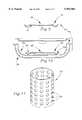
- FIG. 1is a cross-sectional view of a heat retentive food retaining apparatus having a temperature self-regulating core constructed in accordance with a preferred embodiment of the present invention.
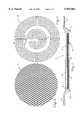
- FIG. 2is a plan view of a heating element of the apparatus of FIG. 1.
- FIG. 3is a cross-sectional view of a member of the heating element of FIG. 2.
- FIG. 4is an alternative embodiment of the apparatus of the present invention.
- FIG. 5is an alternative embodiment of the heating element of the apparatus of FIG. 1.
- FIG. 6is a schematic illustration of a temperature self-regulating, food warming device of the present invention.
- FIG. 6Ais a flow diagram of a conventional no load detection circuit.
- FIG. 6Bis a flow diagram of an alternative no load detection circuit.
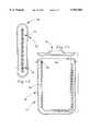
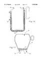
- FIG. 7is an elevational view in partial section of coffee carafe constructed in accordance with an alternative embodiment of the present invention.
- FIG. 8is a plan view of a heating element constructed in accordance with an alternative embodiment of the present invention.
- FIG. 9is a sectional view of the heating element of FIG. 8 taken along line 9--9.
- FIG. 10is a sectional view of a pan including the heating element of FIG. 8.
- FIG. 11is a perspective view of a cylindrical heating element constructed in accordance with an alternative embodiment of the present invention.
- FIG. 12is a sectional view of a heat retentive pellet.
- FIG. 13is a sectional view of a pot constructed in accordance with an alternative embodiment of the present invention.
- FIG. 14is an elevational view in partial section of a food warming device constructed in accordance with an alternative embodiment of the present invention.
- FIG. 15is a sectional view of a coffee cup constructed in accordance with an alternative embodiment of the present invention.
- FIG. 16is a graph illustrating variations in the ferromagnetic Curie temperature T c of Ni--Cu alloys of varying compositions.
- FIG. 1A heat retentive, temperature self-regulating food retaining apparatus 10 constructed in accordance with a preferred embodiment of the present invention is illustrated in FIG. 1.
- the food retaining apparatus 10broadly includes a body 12, a heat retentive core 14, and a magnetic induction heating element 16 imbedded in the core 14.
- the body 12is provided as a food retaining means and includes a generally rigid, food-contacting wall 18, and an annular rim portion 20.
- the wall 18includes a downwardly extending wall portion 22 and defines a cavity 24 configured for receiving the core 14.
- the body 12is constructed from a vitrified ceramic material that has been glazed. Of course, glass, plastic materials, or any other suitable material may also be used.
- the body 12possesses a heat resistance of at least 100° C. (212° F.) and is essentially transparent to electromagnetic energy in both the RF and microwave frequency ranges.
- the food retaining apparatus 10is shaped similar to a conventional plate, and is compatible with commercially available insulated domes. Therefore, the body 12 is generally circular with an outside diameter matching the inside diameter of the dome to be used. Such domes typically have an inside diameter of between about 73/4"-9".
- the wall 18may present a decorative style or design.
- any manner of servingware bodymay be substituted for the above described body 12 so long as the servingware body comprises an open cavity for receiving the heat storage composition of this invention.
- Any shape or type of heat retentive servingwarewill still retain all the advantages of this invention.
- Other contemplated types of heat retentive servingwareinclude bowls, platters, cups, bread plates, all manner of specialized serving dishes, beverage containers, etc.
- the heat retentive core 14is comprised of a heat storage composition matrix of solid state phase change material, ferrite material, a fire retardant additive, and a flexible epoxy binder.
- the heating element 16is imbedded in the core 14 for selective heating of the core 14.
- the solid state phase change materialis advantageously selected from the group consisting of polyhydroxy compounds (e.g., polyhydric alcohols (polyols) and glycols), and the C 2 -C 4 polyalkylenes.
- polyhydroxy compoundsinclude trimethylol ethane, also known as pentaglycerine, pentaerythritol, neopentyl glycol, trimethylol propane, monoaminopentaerythritol, diaminopentaerythritol, tris (hydroxymethyl) acetic acid, cross-linked, high density polyethylene (HDPE) or a mixture of such compounds.
- the C 2 -C 4 polyalkyleneis preferably a cross-linked high density polyethylene.
- Solid state phase change materialprovides sensible heat storage as well as reversible latent heat storage through solid-to-solid, crystalline phase transformations.
- Phase change materialstores vast amounts of latent thermal energy about a single phase transition temperature. The latent thermal energy is emitted in a narrow temperature band centered about a temperature slightly lower than the transition temperature.
- Table 1is taken from "Solid State Phase Transitions in Pentaerythritol and Related Polyhydric Alcohols", Solar Energy Materials, 13 (1986) p. 134, by Benson et al., and shows the thermal properties for some of the above-mentioned polyols.
- the amount of latent thermal energy stored by neopentyl glycol and trimethylol ethaneis comparable to the energy stored by the finest available waxes currently being used in commercially available heat retentive servers, approximately 160 kJ/kg.
- the amount of latent thermal energy stored by pentaerythritolis significantly higher.
- solid state phase change materialshave other more significant advantages over conventional waxes.
- One advantageis that the crystalline phase transition temperature of the solid state phase change materials of the invention can be adjusted over the temperature range of between about 7-200° C. (45-392° F.) by selecting certain of the above-mentioned phase change materials, alone or in suitable mixtures, depending upon the specific phase transition temperature desired.
- Another advantage of the solid state phase change materials over waxesis that the latent heat is stored in a solid-to-solid rather than a solid-to-liquid transition.
- This advantageis a multiple one.
- containmentbecomes less critical and therefore easier. Since during normal use no molten material will exist within the servingware, leakage of dangerously hot fluids is avoided.
- thermal expansion during a crystalline solid-to-solid phase transitionis minimal compared to the expansion undergone by a wax during a solid-to-liquid transition, less room for expansion is required and simpler containment designs may be employed.
- permanently increasing the thermal conductivity of a solid-to-solid phase change material such as a polyolis much easier than doing so for a solid-to-liquid phase change material.
- Trimethylol ethaneis the preferred polyol for use in the heat retentive servingware of this invention.
- the phase transformation temperature of trimethylol ethane of approximately 81° C. (178° F.)is ideal for storage of latent heat in commercially available oven-type heated base dispensers. This material releases its stored latent heat at a temperature less than 81° C. (178° F.) but well above that required to maintain food at temperatures above 60° C. (140° F.) for extended periods of time.
- trimethylol ethaneis extremely low in toxicity, has been approved for food contact use by the FDA, and is readily available at relatively low cost.
- the ferrite powderincreases the magnetic flux density within the heat retentive core for a given magnetic field strength produced by an induction coil.
- the powderincreases the thermal conductivity of the heat retentive core, allowing heat to be transferred throughout the heat storage polyol material more quickly.
- the ferrite powderincreases the magnetic flux density of the food retaining apparatus 10 so that the apparatus 10 is heated more quickly and more efficiently by a magnetic induction heating coil.
- the ferritecan permit several adjacent or stacked plates to be heated simultaneously by a single induction coil.
- the ferritealso increases the generally low thermal conductivity of the polyol material. Ferrites, being ceramic materials in a fully oxidized state, should not degrade the heat storage capacity of the polyol crystals. No known prior art has taught the addition of ferrites to polyols so as to allow them to improve their thermal conductivity while at the same time allow more efficient heating by magnetic induction.
- the ferrite powderpreferably has a high initial permeability, high microwave (particularly 2450 MHz) lossiness, and low lossiness for the RF magnetic induction frequency used to heat the servingware.
- Many commercially available ferriteswhich have been used for years as core materials for transformers and other electrical equipment fit this profile. Such commercial uses require high magnification of the magnetic flux density while having little energy loss at low frequencies due to eddy current production. It is known that ferrites can possess any range of properties by compounding them with zinc, manganese, cobalt, nickel, lithium, iron, or copper as disclosed in two publications: Ferrites, by J. Smit and H. P. J. Wijn, John Wiley and Sons, New York, 1959, page 1, etc. and Ferrites: A Review of Materials and Applications, by F.
- the fire retardant additiveis preferably selected from the group consisting of alpha-alumina trihydrate, the phosphate esters, chlorinated hydrocarbons, bromated hydrocarbons, antimony trioxide, borates, polyols containing phosphorous, and brominated bisphenol A.
- the additiveis added to the polyol/ferrite powder mixture prior to mixing with flexible epoxy binder during core manufacture.
- Alpha-alumina trihydrateis the most preferred fire retardant additive. When alpha-alumina trihydrate is exposed to fire, the hydrate decomposes endothermically, releasing most of its chemically bound water, and acts as a heat sink to absorb the heat of the fire.
- alpha-alumina trihydrateSeveral properties of alpha-alumina trihydrate are advantageous for use in this invention. Being a ceramic, it can be obtained in powder form with average particle size below 10 microns. Micron sized particles allow for homogeneous mixing with the polyol and ferrite in powder form.
- Alpha-alumina trihydrateis also readily available, relatively inexpensive, safe to handle, an has a "generally recognized as safe" (GRAS) rating from the FDA. Finely ground alpha-alumina trihydrate, for example, is used as a constituent in toothpaste.
- GRASgenerally recognized as safe
- the flexible epoxy binderserves as a binder for the heat retentive composition, an encapsulant for the solid state phase change material, an adhesive to maintain thermal contact between the heat retentive core 14 and the body 12, a thermal expansion equalizer (permitting expansion of the solid state phase change material within the composition matrix during phase transformation) and a slow energy release from the polyol to the body 12. Furthermore, the flexible epoxy binder is capable of maintaining its properties at continuous operating temperatures of up to 177° C. (350° F.) and peak temperatures of 204° C. (400° F.).
- the flexible epoxymaintains the thermal contact between the ferrite and the polyol.
- the flexible epoxycoats each particle of the solid state phase change material, acting to keep such particles from contacting the heating element 16. Such contact would eventually degrade the heat storage performance of the polyol.
- the binderacts as a safety encapsulant should gross overheating of the heat retentive apparatus 10 result in the solid state phase change material becoming partially or fully molten.
- the binderensures a long lasting bond between the core 14 and the body 12 by permitting expansion of the phase change material during a phase transformation of between about 5-15% of the volume of the phase change material prior to the transformation.
- the binderensures a slow, steady conduction of heat from the encapsulated polyol to the food-contacting wall 18 and the food contacting the wall 18.
- the preferred flexible epoxy binderis a mixture of three resins and two curing agents.
- the resinsinclude bisphenol A resin, such as Dow D.E.R. 383 resin, novolak epoxy resin, such as Dow D.E.N. 431 resin, and a flexible epoxy resin additive, such as an aliphatic diepoxide.
- Dow D.E.R. 732 resinis a suitable aliphatic diepoxide.
- the curing agentincludes cycloaliphatic amine, such as Ancamine 1770 available from Air Products and Chemicals, Inc., and N-(2-hydroxy ethyl) diethylene triamine, such as Ancamine T also available from Air Products and Chemicals, Inc. Many blend ratios of these three resins and two curing agent may be employed for the products of this invention, depending upon the regulation temperature desired.
- One preferred resin mixture for low temperature applicationincludes 56% by weight bisphenol A resin, 14% by weight novolak epoxy resin, and 30% by weight flexible epoxy resin additive.
- the flexible epoxy resin additivemay be lowered to 25% or raised to 40% by weight while keeping the ratio of bisphenol A to novolak epoxy resin the same.
- the optimum parts per weight of curing agent per hundred parts of this epoxy resin mixtureis about 11 phr Ancamine T and 5 phr Ancamine 1770.
- Another preferred resin mixture for higher temperature applicationsincludes 70% by weight novolak epoxy resin, 10% by weight bisphenol A epoxy resin, and 20% by weight flexible epoxy resin additive.
- the flexible epoxy resin additivemay be lowered to 10% or raised to 30% while keeping the ratio of novolak epoxy resin to bisphenol A the same.
- the optimum parts per weight of curing agent per hundred parts of this epoxy resin mixtureis about 12 phr Ancamine T and 5 phr Ancamine 1700.
- the heating element 16 of this inventionhas several preferred features.
- the element 16is self-regulative at a temperature that is above the phase change temperature, but below the melting temperature of the solid-state phase change material in the core 14.
- the element 16is also self-regulative when heated by commercially available magnetic induction cooking devices that do not employ circuitry to maintain induced current within the heating element 16 at nearly constant levels.
- the element 16transfers heat uniformly to substantially the entire core 14. In addition, the element 16 should take up a minimal space within the core 14.
- the heating element 16 of the present inventionis temperature self-regulating when heated by commercially available magnetic induction cooking devices that do not employ circuitry to maintain induced current within the heating element at nearly constant levels. As noted above, such prior art cooking devices typically employ circuitry designed to prohibit excessively high currents from flowing through the inverter circuit, and hence through the load.
- the heating element 16 of the present inventionis designed to have an impedance when heated above the Curie temperature, whose magnitude, Z min , is below that which triggers the no load detection circuitry of a commercially available magnetic induction cooking device to interrupt its magnetic field generation.
- Z detector 1the magnitude of load impedance that triggers the no load detection circuitry shall be referred to as Z detector 1 .
- the heating element 16also has an impedance when at a temperature less than the Curie temperature whose magnitude, Z max , is significantly greater than Z detector so as to achieve a significant heating rate.
- the impedance, Z, of the element 16is proportional to the equation ( ⁇ /2) 1/2 .
- the maximum impedance, Z maxof the heating element occurs just prior to the Curie temperature, and obeys the following proportionality relationship:
- the minimum impedance, Z minof the heating element occurs just after the Curie temperature, and obeys the following proportionality relationship:
- the heating element 16is constructed from materials to allow a relatively large difference between Z min and Z max . This allows Z min to be designed below Z detector while allowing Z max to be high enough to achieve acceptable heating rates and efficiencies for virtually all commercially available cooking devices.
- the principle of the temperature self-regulating heating element 16is that at a regulation temperature very near its Curie temperature, the impedance of the element 16 drops to a level so that the no-load detection system circuitry of a commercially available cooking device de-energizes the current flowing through the induction heating coil, thereby eliminating magnetic field production and thus interrupting the joule heating of the element 16.
- the impedance of the element 16increases to a level well above that required for the "no-load" detection system circuitry to re-energize the switching elements of the inverter, thereby re-emitting the changing magnetic field.
- joule heatingis re-established. Because this heating/cooling cycle is reversible, the heating element self-regulates about the regulation temperature.
- a flow diagramis illustrated that corresponds to the actions of the conventional no load detection circuitry.
- a magnetic fieldis generated.
- the impedance of the element 16, Z measuredis detected at numeral 1002.
- Z measuredis then compared with Z detector , numeral 1004, and if Z measured is less than Z detector , representative of the temperature of the element 16 being greater than the Curie temperature, the magnetic field is interrupted, numeral 1006.
- the fieldis periodically regenerated so that the impedance of the element 16 may again be detected.
- the fieldwill be interrupted again if Z measured remains below Z detector .
- Z measuredrises above Z detector , representative of a drop in the temperature of the element below the Curie temperature, the magnetic field will remain generated. This series of detector and comparison is continuously repeated while the cooking device is used.
- the temperature at which the heating element 16 self-regulatesmay be adjusted by altering the distance between the heating element 16 and the source of the magnetic field.
- the effective load impedance that the heating element 16 presents to the magnetic induction circuitryis dependent upon the distance between the heating element 16 and the induction heating coil.
- Z maxand thus the difference between Z max and Z detector , is inversely proportional to the distance between the element 16 and the magnetic field source. Because the impedance of the element 16 drops to Z min over a given, finite temperature range, the temperature at which the impedance of the element 16 drops below Z detector may be adjusted throughout the range by adjusting the distance between the element 16 and the magnetic field source.
- FIG. 6BAn alternative method of detecting the impedance of the heating element 16, Z measured , and determining when to interrupt the magnetic field is illustrated in FIG. 6B.
- the alternative methodis configured to eliminate the dependence of the temperature of self-regulation on the distance between the heating element 16 and the magnetic source.
- two comparisonsare made in determining whether to interrupt the magnetic field.
- the first comparisons, numeral 2004,is similar to the comparison shown in the method of FIG. 6A, the measured impedance, Z measured , is compared with a predetermined impedance level, Z 1 . If Z measured is less than Z 1 , the circuitry will interrupt the magnetic field and will cause periodic measurements of the impedance of the heating element 16 to be made. As long as Z measured is greater than Z 1 , a second comparison is made.
- the second comparison, reference numeral 2008is based on the absolute value of the change in the impedance,
- the second comparisoneffectively eliminates the dependence of the self-regulation temperature on the distance between the heating element 16 and the magnetic induction heating coil because the absolute value of the rate of change of the impedance of heating element 16 between Z max and Z min ,
- Testsshow that
- the reason that the first comparison is still neededis that the second comparison alone would not interrupt the magnetic field (after two measurements) if either no load or a heating element already well above its Curie temperature were placed upon the magnetic induction cooking device.
- the heating element 16may be constructed from a single pure ferromagnetic metal or single ferromagnetic alloy having a relative magnetic permeability which drops significantly at temperatures above the Curie temperature.
- the ratio of ⁇ T ⁇ Tc / ⁇ T>Tcis sufficiently close to 1, therefore, the difference between Z max and Z min depends upon the difference between ⁇ r ,T ⁇ Tc and ⁇ r ,T>Tc. Because ⁇ r ,T ⁇ Tc has values which fall in the range from 100 to 1000 for most ferromagnetic metals, and ⁇ r ,T>Tc is approximately equal to one, the difference is significant.
- the ferromagnetic materialis preferably composed of an alloy of nickel with either aluminum, zinc, or copper.
- nickel alloyed with coppershows a linear relationship between the ferromagnetic Curie temperature and the composition percentages. This linear relationship and the miscibility of nickel and copper in each other make an alloy of nickel and copper attractive for use as the material of the heating element 16.
- a greater difference between Z max and Z mincan be achieved when both the electrical resistivity, ⁇ , and the relative magnetic permeability, ⁇ r , of the heating element are made to drop dramatically just after the Curie temperature.
- the characteristicsare yielded when the heating element 16 is constructed from a substrate 26 of non-magnetic material and a layer 28 surrounding the substrate 26 of ferromagnetic material, illustrated in FIG. 3.
- the non-magnetic materialhas high thermal and electrical conductivity, while the ferromagnetic material has low electrical conductivity.
- the impedance of the heating element at temperatures above the Curie temperature, Z minbecomes less due to both a drop in relative magnetic permeability and a drop in electrical resistivity.
- Z maxit is also necessary to maintain the value of Z max high enough to achieve the desirable large difference between Z max and Z min noted above.
- a heating element with a copper or aluminum core and a cladding of a nickel-copper alloyis particularly practical.
- One method to achieve the desired alloy claddingis via electrodeposition.
- the ratio of nickel to copper in the alloy claddingis adjusted primarily by changing the ratio of nickel to copper in the electroplating bath.
- the thickness of the nickel-copper platingis manipulated by adjusting the electroplating time.
- the preferred element 16 of food retaining apparatus 10includes a substrate 26 constructed from aluminum, and a layer 28 surrounding the substrate 26 of a ferromagnetic alloy, as illustrated in FIG. 3.
- the alloyis composed of approximately 78 percent nickel and 22 percent copper, yielding a Curie temperature of approximately 100° C. (212° F.), a temperature above the phase change temperature of trimethylol ethane, 81° C., but well below its melting temperature of 197° C.
- the electrodeposition of the cladded layer 28has an advantage in that only selected complete circuit paths of the inductive heating element may be clad, reducing the cost of the heating element.
- the relatively thinner layer 28may also be bonded to the relatively thicker sheet of copper or aluminum substrate.
- the thin sheet of the desired nickel-copper alloymay be produced by melting the constituent metals together and then forming the sheet as has been described in this disclosure.
- electro-conducting and thermally conducting, temperature resistant bonding methods or agents capable of withstanding the different thermal expansion rates of the substrate and claddingare known in the prior art.
- food retaining apparatus 10includes an element 16 constructed solely from an alloy of approximately 78 percent nickel and 22 percent copper.
- the Curie temperature of the alloyis approximately 100° C. (212° F.), a temperature above the phase change temperature of the preferred phase change material, trimethylol ethane, 81° C. (178° F.), but well below the melting temperature of 197° C. (387° F.) of the phase change material.
- Including copperimproves the thermal conductivity of nickel, thus effecting more efficient transfer of heat throughout the heating element and throughout the heat retentive core.
- the proper proportions of the pure metalsare melted together to form ingots of the alloy. These ingots are then converted into strip or sheet form from which the heating elements may be fabricated, as discussed in more detail below.
- the advantage of the single metal approachis the ease of fabrication after the ingots have been produced.
- a disadvantage of this approachis the higher cost and bulkiness of the element constructed from such an alloy. For example, in order to get the full benefit of the difference between Z max and Z min from a strip of homogeneous nickel/copper alloy, it should be at least one skin depth thick in each temperature range, that is, at temperatures both below and above its Curie temperature.
- the skin depthincreases to approximately 0.038 inches under the same conditions. This latter value of skin depth necessitates a relatively bulky heating element. The material costs of the heating element, of course, increase with bulk.
- the material used to make the heating elementpreferably consists of a core of non-magnetic material with high thermal and electrical conductivity clad with a thin surface layer of a ferromagnetic material of low electrical conductivity.
- the cladding designs described aboveoffer the advantages of reduced cost and bulkiness relative to the heating element constructed entirely from a single ferromagnetic alloy. For example, only a relatively thin surface layer of the nickel-copper alloy need be plated or adhered (approximately 1.5 to 1.8 skin depths) on the much thicker copper or aluminum substrate (approximately 1 skin depth).
- the heating element 16constructed in accordance with a preferred form is illustrated.
- the form of element 16permits element 16 to conduct heat to the core 14 evenly.
- the preferred form of element 16is that of an expanded metal sheet die cut into the shape required to substantially fill the cavity 24 of body 12. Expanded metal sheet begins as ordinary metal sheeting or strip. It is simultaneously slit and stretched by shaped tools which determine the pattern and number of openings. Strand dimensions, width and thickness, overall thickness of the expanded metal sheet, and weight per square inch are controlled variables.
- the Exmet Corporation of Naugatuck, Conn.produces expanded metal to virtually any specification.
- One square foot of ordinary metal sheetingresults in two to three square feet of expanded metal sheet.
- An overall thickness of over 0.100 inchmay result from an ordinary metal sheet thickness of 0.005 inch. This ability to create large overall thicknesses from very thin metal sheet allows the heating element 16 to transfer its heat uniformly to the core 14 while taking up minimal volume of the core 14.
- the size, shape, and number of openings per square inch of the element 16are important specifications.
- the heating element 16has the shape of a circular disc.
- the diameter of the element 16is slightly smaller than the inner diameter of the cavity of the body 12.
- the original sheet thickness of the metal of the elementis approximately from 0.015 to 0.020 inches thick.
- the overall expanded thickness of heating element 16is slightly less than overall thickness of the heat retentive core 14 itself.
- the food retaining apparatusincludes a core retaining cap 30.
- the cap 30is provided to encapsulate the core 14 within the cavity 24, and presents a durable, waterproof, aesthetic surface for the bottom of the apparatus 10.
- the capis constructed from a flexible synthetic resin configured for adhering to the body 12 and permitting slight expansions and contractions of the core to maintain integrity throughout consecutive heat/cool cycles.
- the cap 30may be constructed from the same plastic material as body 12 and then either adhered or welded to body 12.
- the cap 30is preferably constructed from the same flexible epoxy mixture described above for use in the core 14.
- a fire retardant selected from the group noted above, in fine powder form,may be dispensed with the epoxy mixture.
- a pigment of choiceis added for aesthetic purposes.
- the preferred thickness of cap 30is approximately 0.0625 inches.
- the cap 30may alternatively be constructed from material that includes thermoset plastics, such as urea-formaldehyde or phenolic resins, or thermoplastic resins with comparable properties to the flexible epoxy mixture described in this disclosure.
- Food retaining apparatus 10is constructed in the following manner.
- the body 12is provided and turned upside down so that the heating element 16 may be placed into the cavity 24 of body 12.
- the element 16is positioned to rest on the generally flat surface of the cavity 24.
- Several drops of silicone adhesive, such as RTV 102,are then placed upon the heating element to adhere the element 16 to the body 12. After the adhesive has cured, the heating element is in proper position and the heat retentive composition is ready to be placed within the cavity 24 of body 12.
- composition for forming the coreis mixed.
- the preferred polyol, ferrite, and fire retardantwhich are in a dry state, are blended together to yield a homogenous mixture.
- the approximate percentages by weight of the polyol, ferrite and fire retardant for optimum performance of the heat retentive dinner plateare as follows:
- ferrite powder and/or fire retardantmay be eliminated from the dry mixture, in which case its respective percentage by weight would be replaced by polyol.
- the total mass of the dry constituents of the heat retentive composition used in a piece of heat retentive servingware of this inventiondepends upon the size, geometry, and desired heat storage capacity of the servingware.
- the flexible epoxy componentsare then thoroughly mixed, and added to the homogeneously mixed dry constituents under high shear.
- the proper ratio of flexible epoxy to dry constituentsis such that all particles of the polyol may be thoroughly wetted by the epoxy, thus providing the desired encapsulation. It has been found that the optimum percentages by weight of dry and wet ingredients are approximately:
- the height of the mixture above the surface of the heating element 16should be kept low so that joule heating from the heating element 16 during magnetic induction heating may more easily be transferred to all parts of the core 14 formed by the mixture. If the desired thickness of core 14 is significantly greater than the thickest available heating element 16, tests have shown that a layer or layers of copper or aluminum expanded metal mesh may be attached to the heating element 16 (on surface side of the cavity 24 next to the body 12) to provide excellent thermal conductivity while not prohibiting temperature self-regulation of the core 14.
- the apparatus 10is oven cured for approximately 1 hour at about 93° C. (200° F.) and approximately 1 hour at about 121° C. (250° F.). Oven curing the apparatus 10 permits the mixture to set and form the core 14.
- the core retaining capis then poured into place into the cavity 24 of the body 12 so that it covers the core 14. Care is taken to remove air from beneath the level surface of the cap 30.
- the thickness of the cap 30 that covers the surface of the heat retentive compositionshould be chosen so as to provide a durable cover for the bottom of the apparatus 10. The preferred thickness of this layer is approximately 0.0625 inches.
- the food retaining apparatus 10is pre-heated either by being placed into a convection oven at approximately 121° C. (250° F.) for at least one hour, on a magnetic induction cook top for an indeterminate amount of time. Food is then placed upon the top surface of the server so as to keep the food warm for a substantially longer period of time than the prior art devices. An insulated cover placed over the food further prolongs the holding time.
- the alternative embodimentincludes a sheet 32 of sponge rubber positioned beneath the core 14 and above the cap 30.
- the sheet 32decreases the heat losses through the bottom of the apparatus 10.
- the rubber sponge materialis preferably a medium density closed cell silicone rubber sponge sheeting. Other sponge materials with high heat resistance and good flammability rating such as neoprene or nitrile may also be used. The sheeting is about 0.0625 inches thick.
- the die-cut rubber sponge 24may be purchased from Lamatek, Inc. of New Jersey.
- the sheet 32is die cut into the shape of the core 14 and placed on the core 14 prior to curing of the core so that the sheet 32 adheres to the tacky mixture. Care is taken to prevent air pocket formation between the rubber sponge 24 and the mixture. The mixture is then oven cured, and the cap 30 is poured and cured.
- the alternative element 34is relatively thin compared with the preferred element 16, and is used in applications requiring a lower profile.
- the alternative element 34may be constructed from a single, ferromagnetic alloy, or from a non-magnetic substrate having a ferromagnetic layer.
- the alternative element 34is in the shape of a single layer, annular, flat spiral coil with a center terminal end 36 ohmically connected to an outer terminal end 38 by a flat strip 40.
- the strip 40is electrically isolated from all other points of the flat spiral coil. The isolation is accomplished by insulating the coil with a thin layer of temperature resistant paint, enamel, epoxy or other suitable material.
- an adhesiveis used for insulating the strip 40 and coupling the strip 40 with the coil, such as a ceramic adhesive available from Aremco Products, Inc., Ossining, N.Y., or a high-temperature epoxy filled with thermally conductive materials such as alumina.
- the spiral coilis die-cut from a sheet of conducting material. Several nearly identically shaped spiral coils may be advantageously made from the same sheet of conducting material, reducing material costs.
- the element 34may include a switch inbetween end 38 and strip 40 for opening and closing of the electric circuit created by the coil and strip 40.
- the switchmay be used for selectively activating and deactivating the element 34.
- the device 42broadly includes a magnetic induction heater 44 and the food retaining apparatus 10 described above positioned on the heater 44.
- the heaterincludes a holder 46 for holding the apparatus 10, a magnetic field generator 48 and a no load or abnormal load detector 50.
- the generator 48provides a means for generating a magnetic field through the space above the holder 46.
- the no load detector 50provides a means for detecting the impedance of a body positioned on the holder 46 in the magnetic field, and for interrupting the magnetic field when the detected impedance is less than a predetermined value. The operation of detector 50 and interaction with food retaining apparatus 10 are described above.
- the energy efficiency of device 42will be greater than the prior art devices since power is consumed only when the food retaining apparatus 10, or another inductive heating item, is placed on the holder 46.
- the heating element 16will temperature self-regulate the entire core 14 and thus the food retaining apparatus 10 indefinitely while on the heater 44. The user need not worry about thermal runaway of food retaining apparatus 10 since it may be left upon the heater indefinitely, allowing great flexibility of use.
- the heat retentive core 14will keep the food hot for an extended period of time after the apparatus 10 has been removed from the heater.
- the food warming device 42includes an insulated, closable metal cabinet for accepting a column, or several columns, of vertically stacked food retaining apparatus 10.
- the heater 44is positioned within the cabinet.
- a lidis provided for closing the cabinet.
- the magnetic generator of the alternative food warming deviceincludes a magnetic field coil, such as those used in the scanning devices currently being employed in industry to harden metals by magnetic induction. These coils are solenoid shaped with sufficient length to create a nearly uniform magnetic field within the center of the solenoid. The intensity of this magnetic field is increased within the center of the tube by the inherent magnetization of the ferrite material in the dinner plates centered within the induction coil. Electromagnetic shielding to reduce electromagnetic emissions from this device are provided by the metal cabinet and other magnetic shielding methods known in the art.
- the coilis driven by a simple worm gear running down the length of the cabinet, infusing several of the food retaining apparatus 10 at once with energy via magnetic induction.
- This deviceis able to heat the stack of heat retentive dinner plates relatively efficiently and quickly compared with the 1 to 2 hour time required by oven-type heated base dispensers currently used by most hospitals.
- the food retaining apparatus 10are hot only in their center regions, adjacent to the core 14, leaving the rim portion 20 cool to the touch. As a result, unloading and handling the plates is relatively safer than in the prior art.
- the food warming device 42includes an insulated, closable plastic or metal cabinet for accepting a column, or several columns of vertically stacked food retaining apparatus 10, each positioned upon its own heater 44.
- a dooris provided for closing the cabinet.
- the food warming deviceincludes a conveyor belt for transporting a plurality of food warming apparatus 10 between entry and exit positions. Magnetic field generators and no load detectors are positioned along the conveyor so that the food retaining apparatus 10 may be brought to an operating temperature.
- the devicemay be designed to accept a plurality of apparatus 10 either stacked horizontally or vertically.
- an alternative temperature self-regulating food retaining apparatus 100is shown in the form of a coffee carafe.
- the apparatus 100broadly includes a coffee carafe top 102 and a lower portion 104 threadably coupled with the top 102.
- the threaded couplingpermits separation of the top 102 from the lower portion 104 for cleaning.
- the top 102 and lower portion 104may be alternatively adhesively attached to each other.
- the lower portion 104includes a solid sheet heating element 106 for heating of the contents of the apparatus 100.
- the heating element 106is thermally insulated from the non-metallic outside wall of the lower portion 104 via either foam insulation, an air gap, a vacuum space, or any other means of thermal insulation known in the prior art.
- the coffee carafe top 102 as shownis insulated with double clear plastic walls having an air gap in between. The more well insulated the contents of the apparatus 100, the less energy input from the magnetic induction heater 44 is required to maintain the contents at a constant temperature.
- the height adjuster 108is simply a threaded cap 110 that serves as a holder for the coffee carafe.
- the threaded cap 110is rotated by the user to raise the coffee carafe or lower it above a factory set height so as to lower or raise the coffee holding temperature. Since the hold temperature/height relationship appears to be linear, the cap height adjuster is easily calibrated and factory set for a selected hold temperature.
- FIGS. 8 and 9An alternative heating element 150 is configured to be positioned within a food retaining device and is shown in FIGS. 8 and 9.
- the heating element 150is generally disc-shaped and includes structure defining a plurality of apertures 152 through the element 150.
- the element 150may alternatively be of other shapes and sizes.
- a plurality of dimples 154are formed in the element 150. The dimples 154 act to raise the disc from the floor of the food retaining device so that food within the device is permitted to flow through the apertures 152.
- thermally insulated food retaining devicesmay be designed to be extremely energy efficient temperature self-regulating holding devices.
- a typical plastic steam table pan 158has been converted to a temperature self-regulating, thermally insulated device 156.
- the heating element 150is positioned within the pan 158 to permit magnetic induction heating of the contents of the pan 158.
- the device 156includes the pan 158 and an outer sleeve 160 spaced from the pan 158.
- the sleeve 160is preferably constructed from a plastic material such as polycarbonate. While the space between the liner 158 and sleeve 160 provides thermal insulation between the contents of the pan 156 and the sleeve 160, further insulation may be obtained by lining or coating the interior surface of the sleeve 160 with a prior art insulation material.
- a prior art insulation materialis a low emissivity coating, such as that found on film used to thermally insulate office windows. Experimentation using such film available from 3M Corporation has shown that heat losses may be reduced by approximately 25%.
- heating element 150in a device such as 156 is that the element may be conveniently removed and washed periodically. This convenient cleaning ability is especially important for water tanks where mineral deposits build up on conventional heating elements over time. Furthermore, due to the magnetic field frequencies employed in magnetic induction cooking devices, typically in the range 20-50 Khz, the ultrasonic vibrations induced in the element 150 act to resist the buildup of mineral deposits, such as lime, and corrosion.
- a cylindrical heating element 200is shown in FIG. 11.
- the element 200includes open upper and lower ends and wall structure defining a plurality of apertures 202 therethrough.
- the heating element 200is configured for use in reheating of chilled or frozen foods.
- the foodis placed in a suitable container, such as a poly bag, and the heating element 200 is placed within the food.
- the foodis then reheated simply by positioning it so that the heating element 200 is within a magnetic field for inducing a current in the element 200, heating the element 200 and thus reheating the food.
- An advantage of reheating food in such a manneris that it may be done in the same container as it was stored. Furthermore, no overheating of the food can occur because of the temperature self-regulation feature of the element 200.
- a heat retentive pellet 250is illustrated in FIG. 12.
- the pelletincludes an encapsulating shell 252, a heat retentive core 254 positioned within the shell 252, and a heating element 256 embedded in the core 254.
- the core 254 and heating element 256are comparable with core 14 and element 16, respectively, of the preferred embodiment.
- the pellet 250provides a self-contained unit that is capable of storing latent heat for heating of the area surrounding the pellet 250.
- the pellet, or a plurality of pelletsmay be heated via the food warming device 42 described in the disclosure.
- Such a pelletis particularly useful when inserted into an insulated food cart, such as that manufactured by Cambro Manufacturing Company. Tests have shown that a pellet 250 prototype containing 500 g of polyol can increase the temperature holding ability of a Cambro 400MPC insulated by more than 50%.
- a food warming pot 300 employing several of the features of the present inventionis shown in FIG. 13.
- the pot 300includes a lid 301, a body 302 and a liner 304 inserted within the body 302.
- a heating element 306is provided between the body 302 and liner 304 for magnetic induction heating of the contents of the pot 300.
- the heating element 306is similar to element 34 described earlier in this disclosure except that the element 306 is configured to surround the linear 304. By providing the heating element 306 that is configured to surround the majority of the contents of the pot 300, the contents may be more evenly and effectively heated.
- An insulation material 308is additionally provided between the body 302 and liner 304 for insulating the pot 300.
- the insulation material 308may be constructed from the heat retentive matrix described above, but may also be foam or any other suitable insulator.
- the temperature at which self-regulation occursmay be adjusted by varying the distance between the magnetic induction heating element and the magnetic field source.
- variation in the temperature of self-regulationmay be achieved by incorporating a plurality of heating elements, each constructed from material having unique Curie temperatures.
- FIG. 14illustrates a food container 350 in the form of a beverage pitcher including first and second heating elements 352, 354.
- the heating elements 352, 354are similar to element 34 described earlier in this disclosure except that the elements 352, 354 are configured to surround the beverage pitcher.
- a switch 356is coupled with each of the elements 352, 354 for selectively opening and closing the circuits defined by the elements 352, 354. As a result, a user may selectively open the circuit of the first element 352 in order to have the container 350 heated to the self-regulation temperature of the second element 354, and vice versa. Therefore, the switch 356 provides a means for adjusting the temperature of self-regulation.
- the cup 400includes a body 410 constructed from ceramic material.
- the body 410defines a lower cavity 420.
- Heat conductive material 430such as powdered alumina, or the heat retentive matrix of this invention, is positioned within the cavity 420, and a heating element 440 is positioned within the material 430.
- a lower wall 450is provided for encapsulating the material 430 and element 440 within the cavity 420.
- a pair of apertures 460are formed in the wall 450 and may be sealed by an adhesive, such as Ceramabond 569, available from Aremco Products, Inc. of Ossining, N.Y.
- the cup 400is constructed in a multi step process. First, the body 410 is formed presenting cavity 420. Next, the cup 400 is inverted, and the element 440 is positioned within cavity 420. The lower wall 450 having apertures 460 is then positioned to encapsulate the heating element 440 while permitting air flow between the cavity 420 and the ambient air. At this point, the cup 400 is fired, glazed and fired again. After the cup 400 has cooled, the cavity 420 is filled with the material 430. As noted above, the material 430 is preferably a powdered alumina that exhibits sufficient heat conductivity while preventing excessive expansion during heating of the element 440 so as to prevent cracking of the cup 400.
- a layer of foammay be positioned beneath the material 430 for permitting expansion of the material 430 without cracking of the cup 400.
- a phase change materialsuch as that described above, may be substituted for material 430.
- the cup 400is ready for use.
- the cup 400may be heated by magnetic induction prior to being filled with coffee so that the coffee is not cooled by contacting the body 410.
- the cup 400may be advantageously used to inhibit an undesired reduction in the temperature of the coffee.
- the cup 400may be heated by magnetic induction as it is being filled with espresso, thus regulating the temperature of the espresso until the cup is filled and removed.
Landscapes
- Physics & Mathematics (AREA)
- Engineering & Computer Science (AREA)
- Food Science & Technology (AREA)
- Thermal Sciences (AREA)
- Electromagnetism (AREA)
- Cookers (AREA)
- Non-Reversible Transmitting Devices (AREA)
- Central Heating Systems (AREA)
- Thermotherapy And Cooling Therapy Devices (AREA)
- Devices For Warming Or Keeping Food Or Tableware Hot (AREA)
- Fish Paste Products (AREA)
- Baking, Grill, Roasting (AREA)
- Control Of Resistance Heating (AREA)
Abstract
Description
j(x)=j.sub.0 e.sup.-x/δ ( 1)
δ=(2ρ/ωμ).sup.1/2 ( 2)
R.sub.surface =ρ/δ (3)
R.sub.surface =(ωμρ/2).sup.1/2 ( 4)
TABLE 1__________________________________________________________________________ Latent Heat Melting Latent Heat of Transition Molecular of Melting Tempera- Transition TemperatureName Formula Weight (kJ/kg) ture (° C.) (kJ/kg) (° C.)__________________________________________________________________________Pentaerythritol C.sub.5 H.sub.12 O.sub.4 136.15 36.8 258-260 303 184-185 2,2-Bis(hydroxymethyl)-1,3 propanediol!Trimethylol ethane C.sub.5 H.sub.12 O.sub.3 120.15 44.6 197-198 193 81(2-hydroxy-methyl-2-methyl-1,3-propanediolNeopentyl glycol C.sub.5 H.sub.12 O.sub.2 104.15 45.3 125-126 131 40-43(2,2-dimethyl-1,3 propanediol)__________________________________________________________________________
Z.sub.max α(μ.sub.r,T<Tc *ρ.sub.T<Tc) (7)
Z.sub.min α(μ.sub.r,T>Tc *ρ.sub.T>Tc) (8)
______________________________________ Polyol 67% Ferrite Powder 17% Fire Retardant 17%______________________________________
______________________________________dry ingredients 67%flexible epoxy resin 33%______________________________________
Claims (39)
Priority Applications (10)
| Application Number | Priority Date | Filing Date | Title |
|---|---|---|---|
| US08/902,803US5954984A (en) | 1996-07-31 | 1997-07-30 | Heat retentive food servingware with temperature self-regulating phase change core |
| AT97935242TATE306803T1 (en) | 1996-07-31 | 1997-07-31 | HEAT STORAGE BOWL WITH TEMPERATURE SELF-REGULATING STATE-CHANGING HEAT CARRIER |
| EP97935242AEP0916235B1 (en) | 1996-07-31 | 1997-07-31 | Heat retentive food servingware with temperature self-regulating phase change core |
| JP50915198AJP2002516021A (en) | 1996-07-31 | 1997-07-31 | Food Insulator with Self-Regulating Temperature Phase Transition Core |
| DE69736003TDE69736003T2 (en) | 1996-07-31 | 1997-07-31 | HEAT STORAGE BOWL WITH TEMPERATURE SELF-STRAINING STATE-CHANGING HEAT CARRIER |
| AU38228/97AAU735781B2 (en) | 1996-07-31 | 1997-07-31 | Heat retentive food servingware with temperature self-regulating phase change core |
| CN97197173ACN1132505C (en) | 1996-07-31 | 1997-07-31 | Heat retentive food servingware with temperature self-regulating phase change core |
| PCT/US1997/013494WO1998005184A1 (en) | 1996-07-31 | 1997-07-31 | Heat retentive food servingware with temperature self-regulating phase change core |
| CA002261693ACA2261693C (en) | 1996-07-31 | 1997-07-31 | Heat retentive food servingware with temperature self-regulating phase change core |
| ES97935242TES2253780T3 (en) | 1996-07-31 | 1997-07-31 | APPLIANCE FOR FOOD HEATING WITH TEMPERATURE PHASE MODIFICATION NUCLEUS. |
Applications Claiming Priority (4)
| Application Number | Priority Date | Filing Date | Title |
|---|---|---|---|
| US68898796A | 1996-07-31 | 1996-07-31 | |
| US3581597P | 1997-01-13 | 1997-01-13 | |
| US4407497P | 1997-04-24 | 1997-04-24 | |
| US08/902,803US5954984A (en) | 1996-07-31 | 1997-07-30 | Heat retentive food servingware with temperature self-regulating phase change core |
Related Parent Applications (1)
| Application Number | Title | Priority Date | Filing Date |
|---|---|---|---|
| US68898796AContinuation-In-Part | 1996-07-31 | 1996-07-31 |
Publications (1)
| Publication Number | Publication Date |
|---|---|
| US5954984Atrue US5954984A (en) | 1999-09-21 |
Family
ID=27488331
Family Applications (1)
| Application Number | Title | Priority Date | Filing Date |
|---|---|---|---|
| US08/902,803Expired - LifetimeUS5954984A (en) | 1996-07-31 | 1997-07-30 | Heat retentive food servingware with temperature self-regulating phase change core |
Country Status (10)
| Country | Link |
|---|---|
| US (1) | US5954984A (en) |
| EP (1) | EP0916235B1 (en) |
| JP (1) | JP2002516021A (en) |
| CN (1) | CN1132505C (en) |
| AT (1) | ATE306803T1 (en) |
| AU (1) | AU735781B2 (en) |
| CA (1) | CA2261693C (en) |
| DE (1) | DE69736003T2 (en) |
| ES (1) | ES2253780T3 (en) |
| WO (1) | WO1998005184A1 (en) |
Cited By (80)
| Publication number | Priority date | Publication date | Assignee | Title |
|---|---|---|---|---|
| WO2001028296A1 (en)* | 1999-05-26 | 2001-04-19 | Aladdin Temp-Rite, Llc | Heat retentive food storage/delivery container and system |
| US6316753B2 (en)* | 1998-05-19 | 2001-11-13 | Thermal Solutions, Inc. | Induction heating, temperature self-regulating |
| US6384387B1 (en) | 2000-02-15 | 2002-05-07 | Vesture Corporation | Apparatus and method for heated food delivery |
| US6483089B1 (en) | 1999-05-26 | 2002-11-19 | Aladdin Temp-Rite, Llc | Heat retentive food storage/delivery container and system |
| WO2003007767A1 (en)* | 2001-07-20 | 2003-01-30 | Thermotic Developments Limited | Device for the heating of products |
| US6534753B1 (en) | 2000-06-15 | 2003-03-18 | Wilmington Research And Development Corporation | Backup power supply charged by induction driven power supply for circuits accompanying portable heated container |
| US6555789B2 (en) | 2000-02-15 | 2003-04-29 | Vesture Corporation | Apparatus and method for heated food delivery |
| US6635855B1 (en)* | 1999-01-22 | 2003-10-21 | Marino Scaburri | System for heating of bodies in general by induction, especially for cooking food |
| WO2004075703A1 (en)* | 2003-02-25 | 2004-09-10 | Hubert Eric Walter | Appliance for heating meals |
| US20050011883A1 (en)* | 2003-06-27 | 2005-01-20 | S.C. Johnson And Son, Inc. | Dispenser assemblies and systems including a heat storage unit |
| US20050184059A1 (en)* | 2003-06-27 | 2005-08-25 | Clothier Brian L. | Dispenser assemblies and systems including a heat storage unit |
| US6953919B2 (en) | 2003-01-30 | 2005-10-11 | Thermal Solutions, Inc. | RFID-controlled smart range and method of cooking and heating |
| US20050242086A1 (en)* | 2004-04-28 | 2005-11-03 | Mamoru Imura | Radio frequency identification controlled heatable objects |
| US20050252904A1 (en)* | 2004-05-11 | 2005-11-17 | Grabowski Brian M | Heated delivery system |
| US20050285735A1 (en)* | 2004-04-28 | 2005-12-29 | Mamoru Imura | Tag assembly for radio frequency identification controlled heatable objects |
| WO2005122854A1 (en)* | 2004-06-17 | 2005-12-29 | Herving Staale | A device for maintaining temperature in food and drink |
| US20060112834A1 (en)* | 2004-04-28 | 2006-06-01 | Mamoru Imura | Pressure cooker |
| US20070145034A1 (en)* | 2004-04-28 | 2007-06-28 | Mamoru Imura | Stovetop interface, system and methods of temperature control of cookware, and methods of cooking using numerical temperature control |
| EP1393594A4 (en)* | 2001-05-21 | 2007-07-18 | Thermal Solutions Inc | Heat retentive inductive-heatable laminated matrix |
| US20070181563A1 (en)* | 2006-02-05 | 2007-08-09 | Clean Baking Products, Bvba | Plastic food processing utensils comprising a magnetically susceptible component, methods of using, methods of making, and products and apparatus comprising same |
| US20070246037A1 (en)* | 2004-04-30 | 2007-10-25 | Cantu Homaro R | Cooking and serving system and methods |
| US20070256336A1 (en)* | 2006-05-05 | 2007-11-08 | Lung Wai Choi | Induction ironing apparatus and method |
| US20070263699A1 (en)* | 2006-05-09 | 2007-11-15 | Thermal Solutions, Inc. | Magnetic element temperature sensors |
| US20080035548A1 (en)* | 2006-08-01 | 2008-02-14 | Quos, Inc. | Multi-functional filtration and ultra-pure water generator |
| EP1912481A2 (en) | 2003-06-27 | 2008-04-16 | S.C.Johnson & Son, Inc | Dispenser assemblies and systems including a heat storage unit |
| US20080175753A1 (en)* | 2007-01-23 | 2008-07-24 | Thermal Solutions, Inc. | Microwire-controlled autoclave and method |
| US20090084777A1 (en)* | 2006-10-02 | 2009-04-02 | Oh Doo Yong | Cooking device having an induction heating element |
| US7573005B2 (en) | 2004-04-22 | 2009-08-11 | Thermal Solutions, Inc. | Boil detection method and computer program |
| US20090199994A1 (en)* | 2005-01-27 | 2009-08-13 | Sk Kaken Co., Ltd | Composition for heat-storage object formation, heat-storage object, and process for producing heat-storage object |
| US20100000980A1 (en)* | 2008-07-02 | 2010-01-07 | Bogdan Popescu | Induction Heating System with Versatile Inductive Cartridge |
| US20110100980A1 (en)* | 2009-03-13 | 2011-05-05 | Takeshi Kitaizumi | Induction heating cooker and kitchen unit having the same |
| US20120037615A1 (en)* | 2009-05-06 | 2012-02-16 | Gastros Ag | Induction Cookware for Keeping Food Warm |
| US20120118874A1 (en)* | 2008-05-20 | 2012-05-17 | Phillip Williams | Induction Cook-Top Apparatus |
| US8258441B2 (en) | 2006-05-09 | 2012-09-04 | Tsi Technologies Llc | Magnetic element temperature sensors |
| US8263906B2 (en) | 2010-05-11 | 2012-09-11 | Cambro Manufacturing Company | Food warming system |
| US20130015177A1 (en)* | 2011-07-14 | 2013-01-17 | Tsi Technologies Llc | Induction heating system employing induction-heated switched-circuit vessels |
| US8618749B2 (en) | 1999-06-21 | 2013-12-31 | Access Business Group International Llc | Inductively coupled ballast circuit |
| US20140116270A1 (en)* | 2011-06-20 | 2014-05-01 | Roberto Marcato | Thermo plate |
| US8893977B2 (en) | 2010-04-08 | 2014-11-25 | Access Business Group International Llc | Point of sale inductive systems and methods |
| US9012818B1 (en)* | 2010-03-18 | 2015-04-21 | Food Equipment Technologies Company, Inc. | Beverage heating assembly and method |
| CN105029991A (en)* | 2015-07-13 | 2015-11-11 | 浙江飞剑工贸有限公司 | Manufacturing process of three-layer vacuum cup provided with phase-change materials |
| US20160007414A1 (en)* | 2013-03-08 | 2016-01-07 | Electrolux Appliances Aktiebolag | Induction hob |
| WO2015200074A3 (en)* | 2014-06-23 | 2016-03-17 | Ember Technologies, Inc. | Heated or cooled dishware and drinkware |
| US9293617B2 (en) | 2012-12-10 | 2016-03-22 | Honeywell International Inc. | Copolymer of phase change material for thermal management of PV modules |
| US9299594B2 (en) | 2010-07-27 | 2016-03-29 | Taiwan Semiconductor Manufacturing Company, Ltd. | Substrate bonding system and method of modifying the same |
| US20160095170A1 (en)* | 2014-09-29 | 2016-03-31 | Jane Sunghee Kim | Paper cookware |
| CN105476376A (en)* | 2015-12-22 | 2016-04-13 | 征茂德 | Temperature control cup |
| CN105476385A (en)* | 2015-12-22 | 2016-04-13 | 苏州征之魂专利技术服务有限公司 | Heat insulation cup |
| WO2016069349A1 (en)* | 2014-10-28 | 2016-05-06 | Tempra Technology, Inc. | Heat retaining dish assembly and method of heating same |
| US20160153091A1 (en)* | 2014-03-31 | 2016-06-02 | Spp Technologies Co., Ltd. | Heating Device and Plasma Processing Apparatus Provided Therewith |
| US20160286610A1 (en)* | 2014-01-10 | 2016-09-29 | Electrolux Appliances Aktiebolag | Induction cooker |
| US9510398B1 (en)* | 2012-10-29 | 2016-11-29 | The Boeing Company | Induction heating apparatus |
| US20170079326A1 (en)* | 2014-05-21 | 2017-03-23 | Philip Morris Products S.A. | Inductive heating device and system for aerosol-generation |
| US20170140958A1 (en)* | 2014-05-19 | 2017-05-18 | Tokyo Electron Limited | Heater power feeding mechanism |
| CN107135563A (en)* | 2017-06-20 | 2017-09-05 | 上海墨岛节能材料科技有限公司 | It is a kind of can quick-recovery soon self-heating thermal insulation device |
| US9782036B2 (en) | 2015-02-24 | 2017-10-10 | Ember Technologies, Inc. | Heated or cooled portable drinkware |
| US9801482B1 (en) | 2016-05-12 | 2017-10-31 | Ember Technologies, Inc. | Drinkware and plateware and active temperature control module for same |
| US9814331B2 (en)* | 2010-11-02 | 2017-11-14 | Ember Technologies, Inc. | Heated or cooled dishware and drinkware |
| US9848729B2 (en)* | 2011-11-01 | 2017-12-26 | Kenyon International, Inc. | Vibrating cooking system |
| US9863695B2 (en) | 2016-05-02 | 2018-01-09 | Ember Technologies, Inc. | Heated or cooled drinkware |
| US9955529B2 (en) | 2009-01-06 | 2018-04-24 | Access Business Group International Llc | Smart cookware |
| US9967924B2 (en) | 2014-02-25 | 2018-05-08 | James Heczko | Package for storing consumable product, induction heating apparatus for heating package and system including same |
| US20180184489A1 (en)* | 2016-12-22 | 2018-06-28 | Whirlpool Corporation | Induction burner element having a plurality of single piece frames |
| US10010213B2 (en) | 2010-11-02 | 2018-07-03 | Ember Technologies, Inc. | Heated or cooled dishware and drinkware and food containers |
| DE102017104727A1 (en) | 2017-03-07 | 2018-09-13 | Miele & Cie. Kg | Cookware for use with an induction hob |
| US20190110643A1 (en)* | 2017-10-14 | 2019-04-18 | Gloria Contreras | Smart charger plate |
| US10383476B2 (en) | 2016-09-29 | 2019-08-20 | Ember Technologies, Inc. | Heated or cooled drinkware |
| US10433672B2 (en) | 2018-01-31 | 2019-10-08 | Ember Technologies, Inc. | Actively heated or cooled infant bottle system |
| US20200146477A1 (en)* | 2017-07-13 | 2020-05-14 | Ember Technologies, Inc. | Plateware with active temperature control |
| US10670323B2 (en) | 2018-04-19 | 2020-06-02 | Ember Technologies, Inc. | Portable cooler with active temperature control |
| US10989466B2 (en) | 2019-01-11 | 2021-04-27 | Ember Technologies, Inc. | Portable cooler with active temperature control |
| US11118827B2 (en) | 2019-06-25 | 2021-09-14 | Ember Technologies, Inc. | Portable cooler |
| US11162716B2 (en) | 2019-06-25 | 2021-11-02 | Ember Technologies, Inc. | Portable cooler |
| US11668508B2 (en) | 2019-06-25 | 2023-06-06 | Ember Technologies, Inc. | Portable cooler |
| US11737599B2 (en) | 2016-09-21 | 2023-08-29 | Egc Operating Company Llc | Heated dome for food service |
| USD1005781S1 (en) | 2021-01-29 | 2023-11-28 | Duke Manufacturing Co. | Liner for a food holding well |
| US11912465B2 (en) | 2021-01-27 | 2024-02-27 | Duke Manufacturing Co. | Liner for food receiver of food holding apparatus |
| US11950726B2 (en) | 2010-11-02 | 2024-04-09 | Ember Technologies, Inc. | Drinkware container with active temperature control |
| US12013157B2 (en) | 2020-04-03 | 2024-06-18 | Ember Lifesciences, Inc. | Portable cooler with active temperature control |
| US12108512B2 (en) | 2019-06-06 | 2024-10-01 | Kenyon International, Inc. | Cooktop mat with control window |
Families Citing this family (33)
| Publication number | Priority date | Publication date | Assignee | Title |
|---|---|---|---|---|
| DE19729661A1 (en)* | 1997-07-11 | 1999-01-14 | Ego Elektro Geraetebau Gmbh | Heating system especially for electric cooking operations |
| US6005233A (en)* | 1997-07-15 | 1999-12-21 | Aladdin Synergetics, Inc. | Pressure relief system for inductively heated heat retentive server |
| US6232585B1 (en)* | 1998-05-19 | 2001-05-15 | Thermal Solutions, Inc. | Temperature self-regulating food delivery system |
| DE10018938A1 (en)* | 2000-04-17 | 2001-10-18 | Merck Patent Gmbh | Storage media for latent heat storage |
| US7102103B2 (en) | 2003-02-14 | 2006-09-05 | Carrier Commercial Refrigeration, Inc. | Banquet cart including heat retention material |
| CN100384358C (en)* | 2005-06-30 | 2008-04-30 | 哈尔滨工业大学 | food warmer |
| WO2007071568A1 (en)* | 2005-12-20 | 2007-06-28 | Arcelik Anonim Sirketi | A cooking container for induction heaters |
| EP1880646B1 (en)* | 2006-07-21 | 2010-04-14 | Schmalz Distributions-Systeme AG | Device for providing food and method for providing prepared food |
| DE102007036334A1 (en)* | 2007-08-02 | 2009-02-05 | Electrolux Home Products Corporation N.V. | Base unit for inductive heating of e.g. coffee in coffee brew unit, has control system controlling operation of induction coil so that operation of coil is stably suppressible during measurement of value or range of measured parameter |
| US8448809B2 (en) | 2007-10-15 | 2013-05-28 | Millercoors, Llc | Thermal barrier liner for containers |
| CA2752775C (en)* | 2007-10-15 | 2013-03-12 | Coors Brewing Company | Insulated beverage container and method |
| DE102008035686A1 (en) | 2008-05-30 | 2009-12-03 | Hupfer Metallwerke Gmbh & Co. Kg | Arrangement for inductive heating of dishes arranged on plates |
| GB0919913D0 (en)* | 2009-11-13 | 2009-12-30 | Mcwilliams Kevin | Product warming device |
| US9259886B2 (en) | 2009-12-15 | 2016-02-16 | The Boeing Company | Curing composites out-of-autoclave using induction heating with smart susceptors |
| JP5759116B2 (en)* | 2010-06-28 | 2015-08-05 | 理想科学工業株式会社 | Inkjet printing device |
| US9820339B2 (en)* | 2011-09-29 | 2017-11-14 | The Boeing Company | Induction heating using induction coils in series-parallel circuits |
| DE202012104657U1 (en)* | 2012-11-30 | 2014-03-05 | Wik Far East Ltd. | Electric device for heating a particular liquid food |
| JP2014113222A (en)* | 2012-12-06 | 2014-06-26 | Shinano Kagaku Kogyo Kk | Dish and heating device for dish |
| DE102013206870A1 (en)* | 2013-04-16 | 2014-10-16 | E.G.O. Elektro-Gerätebau GmbH | Induction heating device with an induction coil and method for producing an induction heater |
| ITMI20131731A1 (en)* | 2013-10-17 | 2015-04-18 | Tavola S R L | HEATING SYSTEM FOR INDUCTION HEATING OF THE TYPE PROVIDED WITH A PORCELAIN HOLDER TRAY |
| CN103932562A (en)* | 2014-04-08 | 2014-07-23 | 陈华 | Dinner plate allowed to be heated |
| DE202015102627U1 (en)* | 2015-05-21 | 2016-08-25 | Stephanie Steinhagen | Heat storage unit |
| CN106983265A (en)* | 2017-04-28 | 2017-07-28 | 镇江华源晋昌电器有限公司 | A kind of heat storing and heat preserving kettle |
| FR3067239B1 (en)* | 2017-06-08 | 2019-09-27 | Seb S.A. | DEVICE FOR HEATING A COOKING CONTAINER |
| CN107374256A (en)* | 2017-09-11 | 2017-11-24 | 刘岩松 | Cup is not scalded in one kind insulation |
| FR3073701B1 (en)* | 2017-11-13 | 2019-10-11 | Seb S.A. | DEVICE FOR LIMITING OR REGULATING TEMPERATURE FOR A KITCHEN UTENSIL |
| KR102551348B1 (en) | 2017-12-28 | 2023-07-05 | 제이티 인터내셔널 소시에떼 아노님 | Induction Heating Assemblies for Steam Generators |
| CN108378651B (en)* | 2018-05-28 | 2024-05-03 | 北京梦之墨科技有限公司 | Thermos cup |
| BE1026686B1 (en)* | 2018-10-05 | 2020-05-07 | Promeco Nv | Method for producing crockery filled with phase transition material |
| CN109171399A (en)* | 2018-11-19 | 2019-01-11 | 北矿科技股份有限公司 | A kind of heating and thermal insulation magnetic cup |
| JP7429518B2 (en)* | 2019-11-01 | 2024-02-08 | パーソルエクセルHrパートナーズ株式会社 | liquid heating device |
| CN113242623B (en)* | 2021-05-13 | 2024-04-30 | 烟台大学 | Pipeline type fluid temperature rising device for metal electromagnetic induction heating-phase change heat storage |
| DE202022101796U1 (en) | 2022-04-04 | 2023-07-07 | Eric Mäurer | Inductive dinnerware |
Citations (42)
| Publication number | Priority date | Publication date | Assignee | Title |
|---|---|---|---|---|
| US1975438A (en)* | 1931-09-09 | 1934-10-02 | Ugine Infra | Magnetic muffle or other body and method of varying the magnetic transformation thereof |
| US1975436A (en)* | 1929-11-08 | 1934-10-02 | Ugine Infra | Method of heating by induction and furnace therefor |
| US1975437A (en)* | 1931-01-28 | 1934-10-02 | Ugine Infra | Induction heated furnace |
| US3734077A (en)* | 1972-03-15 | 1973-05-22 | American Hospital Supply Corp | Heat-retaining food server |
| US3745290A (en)* | 1972-03-01 | 1973-07-10 | Gen Electric | Inductively heatable utensils or vessels for heating,serving and storing food |
| US3777094A (en)* | 1971-09-09 | 1973-12-04 | Environment One Corp | Thermally insulated cookware for dynamic induction field heating and cooking apparatus |
| US3916872A (en)* | 1974-04-05 | 1975-11-04 | Kreis Ag | Heat storage dish |
| US3978307A (en)* | 1972-11-15 | 1976-08-31 | Matsushita Electric Industrial Co., Ltd. | Induction heating apparatus with protective circuit arrangement |
| US3979572A (en)* | 1974-10-29 | 1976-09-07 | Mitsubishi Denki Kabushiki Kaisha | Induction heating apparatus |
| US4020310A (en)* | 1975-03-20 | 1977-04-26 | Souder Jr James J | Container for inductively heating food |
| US4110587A (en)* | 1975-03-20 | 1978-08-29 | Patents Licensing International, Ltd. | Method and apparatus for heating food |
| US4115676A (en)* | 1976-02-10 | 1978-09-19 | Tokyo Shibaura Electric Co., Ltd. | Induction heating apparatus |
| US4235282A (en)* | 1976-12-31 | 1980-11-25 | Filippis Modeste De | Heating and refrigerating tray cabinet for distributing hot and cold dishes |
| US4246884A (en)* | 1979-08-17 | 1981-01-27 | Mcgraw-Edison Company | Plate warmer |
| US4256945A (en)* | 1979-08-31 | 1981-03-17 | Iris Associates | Alternating current electrically resistive heating element having intrinsic temperature control |
| US4266108A (en)* | 1979-03-28 | 1981-05-05 | The Pillsbury Company | Microwave heating device and method |
| US4527031A (en)* | 1984-06-13 | 1985-07-02 | Aparicio Luis R | Electromechanical system for generating heat in metallic vessels |
| US4533807A (en)* | 1982-04-27 | 1985-08-06 | Asahi Kogyo Kabushiki Kaisha | Cooking utensil for induction cooking apparatus |
| US4544818A (en)* | 1982-07-29 | 1985-10-01 | Asahi Giken Kogyo Kabushiki Kaisha | Cooking utensil for induction cooking apparatus |
| US4567877A (en)* | 1984-07-30 | 1986-02-04 | Bahman Sepahpur | Heat storage food container |
| US4572864A (en)* | 1985-01-04 | 1986-02-25 | The United States Of America As Represented By The United States Department Of Energy | Composite materials for thermal energy storage |
| US4614852A (en)* | 1985-07-30 | 1986-09-30 | Nippon Light Metal Company Limited | Electromagnetic induction heating cooking utensil |
| US4625098A (en)* | 1984-10-16 | 1986-11-25 | Joe Do S | Cookware having integrally formed natural stone bottoms and method of manufacturing the same |
| US4646935A (en)* | 1985-01-18 | 1987-03-03 | Clad Metals, Inc. | Induction cooking utensils |
| US4774395A (en)* | 1984-12-18 | 1988-09-27 | Matsushita Electric Industrial Co., Ltd. | Electric heat storage apparatus employing pentaerythritol heat storage compositions |
| US4776386A (en)* | 1985-04-29 | 1988-10-11 | Hermann Meier | Apparatus for cooling, storing and reheating food using induction heating |
| US4914267A (en)* | 1982-12-01 | 1990-04-03 | Metcal, Inc. | Connector containing fusible material and having intrinsic temperature control |
| US4982722A (en)* | 1989-06-06 | 1991-01-08 | Aladdin Synergetics, Inc. | Heat retentive server with phase change core |
| US4983798A (en)* | 1989-04-18 | 1991-01-08 | Eckler Paul E | Warming devices and method using a material with a solid-solid phase change |
| US4987828A (en)* | 1987-12-01 | 1991-01-29 | Electricite De France - Service National | Inductive heating apparatus for cooking thin dishes such as omelets, quiches or the like |
| US5125391A (en)* | 1991-10-10 | 1992-06-30 | Servolift Eastern Corporation | Heat-retaining food service container |
| US5129314A (en)* | 1992-02-07 | 1992-07-14 | Hu Loong Chiang | Electric wok |
| US5194708A (en)* | 1990-08-24 | 1993-03-16 | Metcal, Inc. | Transverse electric heater |
| US5202150A (en)* | 1991-03-13 | 1993-04-13 | The United States Of America As Represented By The United States Department Of Energy | Microwave impregnation of porous materials with thermal energy storage materials |
| US5227597A (en)* | 1990-02-16 | 1993-07-13 | Electric Power Research Institute | Rapid heating, uniform, highly efficient griddle |
| US5254380A (en)* | 1985-11-22 | 1993-10-19 | University Of Dayton | Dry powder mixes comprising phase change materials |
| US5424519A (en)* | 1993-09-21 | 1995-06-13 | Battelle Memorial Institute | Microwaved-activated thermal storage material; and method |
| US5466915A (en)* | 1992-10-07 | 1995-11-14 | Berndorf Luzern A.G. | Tray transport cart having electromagnetic induction heaters for heating meals to be placed on the trays |
| US5487329A (en)* | 1994-04-15 | 1996-01-30 | Vesta Ag & Co. Ohg | Cooking or boiling pot |
| US5603858A (en)* | 1995-06-02 | 1997-02-18 | Aladdin Synergetics, Inc. | Heat retentive server for induction heating |
| US5611328A (en)* | 1995-09-19 | 1997-03-18 | Seco Products Corporation | Heat retentive food service base |
| US5643485A (en)* | 1988-04-15 | 1997-07-01 | Midwest Research Institute | Cooking utensil with improved heat retention |
Family Cites Families (3)
| Publication number | Priority date | Publication date | Assignee | Title |
|---|---|---|---|---|
| US4454403A (en) | 1980-12-01 | 1984-06-12 | Raytheon Company | Microwave heating method and apparatus |
| US5052369A (en)* | 1985-12-13 | 1991-10-01 | Johnson Kendrick A | Heat retaining food container |
| US5079398A (en) | 1989-11-27 | 1992-01-07 | Pre Finish Metals Incorporated | Container with ferrite coating and method of making ferrite-coated sheet |
- 1997
- 1997-07-30USUS08/902,803patent/US5954984A/ennot_activeExpired - Lifetime
- 1997-07-31ATAT97935242Tpatent/ATE306803T1/ennot_activeIP Right Cessation
- 1997-07-31ESES97935242Tpatent/ES2253780T3/ennot_activeExpired - Lifetime
- 1997-07-31EPEP97935242Apatent/EP0916235B1/ennot_activeExpired - Lifetime
- 1997-07-31DEDE69736003Tpatent/DE69736003T2/ennot_activeExpired - Lifetime
- 1997-07-31JPJP50915198Apatent/JP2002516021A/ennot_activeCeased
- 1997-07-31WOPCT/US1997/013494patent/WO1998005184A1/enactiveIP Right Grant
- 1997-07-31AUAU38228/97Apatent/AU735781B2/ennot_activeExpired
- 1997-07-31CACA002261693Apatent/CA2261693C/ennot_activeExpired - Lifetime
- 1997-07-31CNCN97197173Apatent/CN1132505C/ennot_activeExpired - Lifetime
Patent Citations (42)
| Publication number | Priority date | Publication date | Assignee | Title |
|---|---|---|---|---|
| US1975436A (en)* | 1929-11-08 | 1934-10-02 | Ugine Infra | Method of heating by induction and furnace therefor |
| US1975437A (en)* | 1931-01-28 | 1934-10-02 | Ugine Infra | Induction heated furnace |
| US1975438A (en)* | 1931-09-09 | 1934-10-02 | Ugine Infra | Magnetic muffle or other body and method of varying the magnetic transformation thereof |
| US3777094A (en)* | 1971-09-09 | 1973-12-04 | Environment One Corp | Thermally insulated cookware for dynamic induction field heating and cooking apparatus |
| US3745290A (en)* | 1972-03-01 | 1973-07-10 | Gen Electric | Inductively heatable utensils or vessels for heating,serving and storing food |
| US3734077A (en)* | 1972-03-15 | 1973-05-22 | American Hospital Supply Corp | Heat-retaining food server |
| US3978307A (en)* | 1972-11-15 | 1976-08-31 | Matsushita Electric Industrial Co., Ltd. | Induction heating apparatus with protective circuit arrangement |
| US3916872A (en)* | 1974-04-05 | 1975-11-04 | Kreis Ag | Heat storage dish |
| US3979572A (en)* | 1974-10-29 | 1976-09-07 | Mitsubishi Denki Kabushiki Kaisha | Induction heating apparatus |
| US4110587A (en)* | 1975-03-20 | 1978-08-29 | Patents Licensing International, Ltd. | Method and apparatus for heating food |
| US4020310A (en)* | 1975-03-20 | 1977-04-26 | Souder Jr James J | Container for inductively heating food |
| US4115676A (en)* | 1976-02-10 | 1978-09-19 | Tokyo Shibaura Electric Co., Ltd. | Induction heating apparatus |
| US4235282A (en)* | 1976-12-31 | 1980-11-25 | Filippis Modeste De | Heating and refrigerating tray cabinet for distributing hot and cold dishes |
| US4266108A (en)* | 1979-03-28 | 1981-05-05 | The Pillsbury Company | Microwave heating device and method |
| US4246884A (en)* | 1979-08-17 | 1981-01-27 | Mcgraw-Edison Company | Plate warmer |
| US4256945A (en)* | 1979-08-31 | 1981-03-17 | Iris Associates | Alternating current electrically resistive heating element having intrinsic temperature control |
| US4533807A (en)* | 1982-04-27 | 1985-08-06 | Asahi Kogyo Kabushiki Kaisha | Cooking utensil for induction cooking apparatus |
| US4544818A (en)* | 1982-07-29 | 1985-10-01 | Asahi Giken Kogyo Kabushiki Kaisha | Cooking utensil for induction cooking apparatus |
| US4914267A (en)* | 1982-12-01 | 1990-04-03 | Metcal, Inc. | Connector containing fusible material and having intrinsic temperature control |
| US4527031A (en)* | 1984-06-13 | 1985-07-02 | Aparicio Luis R | Electromechanical system for generating heat in metallic vessels |
| US4567877A (en)* | 1984-07-30 | 1986-02-04 | Bahman Sepahpur | Heat storage food container |
| US4625098A (en)* | 1984-10-16 | 1986-11-25 | Joe Do S | Cookware having integrally formed natural stone bottoms and method of manufacturing the same |
| US4774395A (en)* | 1984-12-18 | 1988-09-27 | Matsushita Electric Industrial Co., Ltd. | Electric heat storage apparatus employing pentaerythritol heat storage compositions |
| US4572864A (en)* | 1985-01-04 | 1986-02-25 | The United States Of America As Represented By The United States Department Of Energy | Composite materials for thermal energy storage |
| US4646935A (en)* | 1985-01-18 | 1987-03-03 | Clad Metals, Inc. | Induction cooking utensils |
| US4776386A (en)* | 1985-04-29 | 1988-10-11 | Hermann Meier | Apparatus for cooling, storing and reheating food using induction heating |
| US4614852A (en)* | 1985-07-30 | 1986-09-30 | Nippon Light Metal Company Limited | Electromagnetic induction heating cooking utensil |
| US5254380A (en)* | 1985-11-22 | 1993-10-19 | University Of Dayton | Dry powder mixes comprising phase change materials |
| US4987828A (en)* | 1987-12-01 | 1991-01-29 | Electricite De France - Service National | Inductive heating apparatus for cooking thin dishes such as omelets, quiches or the like |
| US5643485A (en)* | 1988-04-15 | 1997-07-01 | Midwest Research Institute | Cooking utensil with improved heat retention |
| US4983798A (en)* | 1989-04-18 | 1991-01-08 | Eckler Paul E | Warming devices and method using a material with a solid-solid phase change |
| US4982722A (en)* | 1989-06-06 | 1991-01-08 | Aladdin Synergetics, Inc. | Heat retentive server with phase change core |
| US5227597A (en)* | 1990-02-16 | 1993-07-13 | Electric Power Research Institute | Rapid heating, uniform, highly efficient griddle |
| US5194708A (en)* | 1990-08-24 | 1993-03-16 | Metcal, Inc. | Transverse electric heater |
| US5202150A (en)* | 1991-03-13 | 1993-04-13 | The United States Of America As Represented By The United States Department Of Energy | Microwave impregnation of porous materials with thermal energy storage materials |
| US5125391A (en)* | 1991-10-10 | 1992-06-30 | Servolift Eastern Corporation | Heat-retaining food service container |
| US5129314A (en)* | 1992-02-07 | 1992-07-14 | Hu Loong Chiang | Electric wok |
| US5466915A (en)* | 1992-10-07 | 1995-11-14 | Berndorf Luzern A.G. | Tray transport cart having electromagnetic induction heaters for heating meals to be placed on the trays |
| US5424519A (en)* | 1993-09-21 | 1995-06-13 | Battelle Memorial Institute | Microwaved-activated thermal storage material; and method |
| US5487329A (en)* | 1994-04-15 | 1996-01-30 | Vesta Ag & Co. Ohg | Cooking or boiling pot |
| US5603858A (en)* | 1995-06-02 | 1997-02-18 | Aladdin Synergetics, Inc. | Heat retentive server for induction heating |
| US5611328A (en)* | 1995-09-19 | 1997-03-18 | Seco Products Corporation | Heat retentive food service base |
Non-Patent Citations (15)
| Title |
|---|
| Carter Hoffmann Corp.; Patient meal make up and delivery systems offer you better choices.* |
| Carter-Hoffmann Corp.; Patient meal make-up and delivery systems offer you better choices. |
| Metcal, The SmartHeat Company; Metcal SSC Soldering Cartridges.* |
| Metcal, The SmartHeat Company; Metcal STSS Systems.* |
| Metcal, The SmartHeat Company; Metcal Tips and Accessories.* |
| Seco Products Corporation; Healthcare Mini Catalog.* |
| Seco Products Corporation; System 9 9 Unitized Base.* |
| Seco Products Corporation; System 9 Combination Base/China Dispenser Base/Tray Dispenser.* |
| Seco Products Corporation; System 9 Molded Cover for 9 Unitized Base, System 7 Molded Cover for 7 3/4 Unitized Base.* |
| Seco Products Corporation; System 9-9" Unitized Base. |
| Seco Products Corporation; System 9-Combination Base/China Dispenser Base/Tray Dispenser. |
| Seco Products Corporation; System 9-Molded Cover for 9" Unitized Base, System 7-Molded Cover for 7-3/4" Unitized Base. |
| Seco Products Corporation; Unitized Base Dispenser.* |
| Therma systems Corporation; Solutions Made Easy.* |
| Therma-systems Corporation; Solutions Made Easy. |
Cited By (166)
| Publication number | Priority date | Publication date | Assignee | Title |
|---|---|---|---|---|
| US6316753B2 (en)* | 1998-05-19 | 2001-11-13 | Thermal Solutions, Inc. | Induction heating, temperature self-regulating |
| US6444961B2 (en)* | 1998-05-19 | 2002-09-03 | Thermal Solutions, Inc. | Induction heating pizza delivery systems |
| US6504135B2 (en)* | 1998-05-19 | 2003-01-07 | Thermal Solutions, Inc. | Temperature self-regulating food delivery system |
| US6635855B1 (en)* | 1999-01-22 | 2003-10-21 | Marino Scaburri | System for heating of bodies in general by induction, especially for cooking food |
| US6350972B1 (en) | 1999-05-26 | 2002-02-26 | Aladdin Temp-Rite, Llc | Induction-based heated delivery container system |
| US6483089B1 (en) | 1999-05-26 | 2002-11-19 | Aladdin Temp-Rite, Llc | Heat retentive food storage/delivery container and system |
| WO2001028296A1 (en)* | 1999-05-26 | 2001-04-19 | Aladdin Temp-Rite, Llc | Heat retentive food storage/delivery container and system |
| US9590456B2 (en) | 1999-06-21 | 2017-03-07 | Access Business Group International Llc | Inductively coupled ballast circuit |
| US9397524B2 (en) | 1999-06-21 | 2016-07-19 | Access Business Group International Llc | Inductively coupled ballast circuit |
| US10014722B2 (en) | 1999-06-21 | 2018-07-03 | Philips Ip Ventures B.V. | Inductively coupled ballast circuit |
| US8618749B2 (en) | 1999-06-21 | 2013-12-31 | Access Business Group International Llc | Inductively coupled ballast circuit |
| US9299493B2 (en) | 1999-06-21 | 2016-03-29 | Access Business Group International Llc | Inductively coupled ballast circuit |
| US6555789B2 (en) | 2000-02-15 | 2003-04-29 | Vesture Corporation | Apparatus and method for heated food delivery |
| US6861628B2 (en) | 2000-02-15 | 2005-03-01 | Vesture Corporation | Apparatus and method for heated food delivery |
| US6555799B2 (en) | 2000-02-15 | 2003-04-29 | Vesture Corporation | Apparatus and method for heated food delivery |
| US6989517B2 (en) | 2000-02-15 | 2006-01-24 | Vesture Corporation | Apparatus and method for heated food delivery |
| US6384387B1 (en) | 2000-02-15 | 2002-05-07 | Vesture Corporation | Apparatus and method for heated food delivery |
| US6566634B2 (en) | 2000-06-15 | 2003-05-20 | Wilmington Research And Development Corporation | Induction driven power supply for circuits accompanying portable heated items |
| US6534753B1 (en) | 2000-06-15 | 2003-03-18 | Wilmington Research And Development Corporation | Backup power supply charged by induction driven power supply for circuits accompanying portable heated container |
| EP1393594A4 (en)* | 2001-05-21 | 2007-07-18 | Thermal Solutions Inc | Heat retentive inductive-heatable laminated matrix |
| WO2003007767A1 (en)* | 2001-07-20 | 2003-01-30 | Thermotic Developments Limited | Device for the heating of products |
| USRE42513E1 (en) | 2003-01-30 | 2011-07-05 | Hr Technology, Inc. | RFID—controlled smart range and method of cooking and heating |
| US6953919B2 (en) | 2003-01-30 | 2005-10-11 | Thermal Solutions, Inc. | RFID-controlled smart range and method of cooking and heating |
| US20060219704A1 (en)* | 2003-02-25 | 2006-10-05 | Appliance for heating meals | |
| US7615727B2 (en) | 2003-02-25 | 2009-11-10 | Mgs Modular Galley Systems Ag | Appliance for heating meals |
| WO2004075703A1 (en)* | 2003-02-25 | 2004-09-10 | Hubert Eric Walter | Appliance for heating meals |
| US20050184059A1 (en)* | 2003-06-27 | 2005-08-25 | Clothier Brian L. | Dispenser assemblies and systems including a heat storage unit |
| EP1912481A2 (en) | 2003-06-27 | 2008-04-16 | S.C.Johnson & Son, Inc | Dispenser assemblies and systems including a heat storage unit |
| US20050011883A1 (en)* | 2003-06-27 | 2005-01-20 | S.C. Johnson And Son, Inc. | Dispenser assemblies and systems including a heat storage unit |
| US7208707B2 (en) | 2003-06-27 | 2007-04-24 | S.C. Johnson & Son, Inc. | Dispenser assemblies and systems including a heat storage unit |
| US7227108B2 (en) | 2003-06-27 | 2007-06-05 | S.C. Johnson & Son, Inc. | Dispenser assemblies and systems including a heat storage unit |
| US20070131676A1 (en)* | 2003-06-27 | 2007-06-14 | Clothier Brian L | Dispenser assemblies and systems including a heat storage unit |
| US7573005B2 (en) | 2004-04-22 | 2009-08-11 | Thermal Solutions, Inc. | Boil detection method and computer program |
| US7935914B2 (en) | 2004-04-28 | 2011-05-03 | Mamoru Imura | Pressure cooker |
| US20060112834A1 (en)* | 2004-04-28 | 2006-06-01 | Mamoru Imura | Pressure cooker |
| US20050242086A1 (en)* | 2004-04-28 | 2005-11-03 | Mamoru Imura | Radio frequency identification controlled heatable objects |
| US20050285735A1 (en)* | 2004-04-28 | 2005-12-29 | Mamoru Imura | Tag assembly for radio frequency identification controlled heatable objects |
| US8212189B2 (en) | 2004-04-28 | 2012-07-03 | Mamoru Imura | Stovetop interface, system and methods of temperature control of cookware, and methods of cooking using numerical temperature control |
| US7157675B2 (en) | 2004-04-28 | 2007-01-02 | Imura International U.S.A. Inc. | Radio frequency identification controlled heatable objects |
| US7875836B2 (en) | 2004-04-28 | 2011-01-25 | Mamoru Imura | Tag assembly for radio frequency identification controlled heatable objects |
| US20070145034A1 (en)* | 2004-04-28 | 2007-06-28 | Mamoru Imura | Stovetop interface, system and methods of temperature control of cookware, and methods of cooking using numerical temperature control |
| US7690294B2 (en) | 2004-04-30 | 2010-04-06 | Cantu Homaro R | Cooking and serving system and methods |
| US20070246037A1 (en)* | 2004-04-30 | 2007-10-25 | Cantu Homaro R | Cooking and serving system and methods |
| US20050252904A1 (en)* | 2004-05-11 | 2005-11-17 | Grabowski Brian M | Heated delivery system |
| US7034254B2 (en) | 2004-05-11 | 2006-04-25 | The Scott Fetzer Company | Heated delivery system |
| US20080000895A1 (en)* | 2004-06-17 | 2008-01-03 | Stale Herving | Device for Maintaining Temperature in Food and Drink |
| US7750273B2 (en) | 2004-06-17 | 2010-07-06 | Herving Staale | Induction cooking mat for maintaining temperature in food and drink |
| WO2005122854A1 (en)* | 2004-06-17 | 2005-12-29 | Herving Staale | A device for maintaining temperature in food and drink |
| US8045846B2 (en)* | 2005-01-27 | 2011-10-25 | Sk Kaken Co., Ltd. | Composition for heat-storage object formation, heat-storage object, and process for producing heat-storage object |
| US20090199994A1 (en)* | 2005-01-27 | 2009-08-13 | Sk Kaken Co., Ltd | Composition for heat-storage object formation, heat-storage object, and process for producing heat-storage object |
| US20070181563A1 (en)* | 2006-02-05 | 2007-08-09 | Clean Baking Products, Bvba | Plastic food processing utensils comprising a magnetically susceptible component, methods of using, methods of making, and products and apparatus comprising same |
| US7681342B2 (en) | 2006-05-05 | 2010-03-23 | Lung Wai Choi | Induction ironing apparatus and method |
| US20070256336A1 (en)* | 2006-05-05 | 2007-11-08 | Lung Wai Choi | Induction ironing apparatus and method |
| US7794142B2 (en) | 2006-05-09 | 2010-09-14 | Tsi Technologies Llc | Magnetic element temperature sensors |
| US20070263699A1 (en)* | 2006-05-09 | 2007-11-15 | Thermal Solutions, Inc. | Magnetic element temperature sensors |
| US8258441B2 (en) | 2006-05-09 | 2012-09-04 | Tsi Technologies Llc | Magnetic element temperature sensors |
| US20080035548A1 (en)* | 2006-08-01 | 2008-02-14 | Quos, Inc. | Multi-functional filtration and ultra-pure water generator |
| US20090084777A1 (en)* | 2006-10-02 | 2009-04-02 | Oh Doo Yong | Cooking device having an induction heating element |
| US8192080B2 (en) | 2007-01-23 | 2012-06-05 | Tsi Technologies Llc | Microwire-controlled autoclave and method |
| US20080175753A1 (en)* | 2007-01-23 | 2008-07-24 | Thermal Solutions, Inc. | Microwire-controlled autoclave and method |
| US10652958B2 (en) | 2008-05-20 | 2020-05-12 | Kenyon International, Inc. | Induction cook-top apparatus |
| US10064246B2 (en) | 2008-05-20 | 2018-08-28 | Kenyon International, Inc. | Induction cook-top apparatus |
| US20120118874A1 (en)* | 2008-05-20 | 2012-05-17 | Phillip Williams | Induction Cook-Top Apparatus |
| US9095005B2 (en)* | 2008-05-20 | 2015-07-28 | Kenyon International, Inc. | Induction cook-top apparatus |
| US20100000980A1 (en)* | 2008-07-02 | 2010-01-07 | Bogdan Popescu | Induction Heating System with Versatile Inductive Cartridge |
| US9955529B2 (en) | 2009-01-06 | 2018-04-24 | Access Business Group International Llc | Smart cookware |
| US20110100980A1 (en)* | 2009-03-13 | 2011-05-05 | Takeshi Kitaizumi | Induction heating cooker and kitchen unit having the same |
| US8878108B2 (en)* | 2009-03-13 | 2014-11-04 | Panasonic Corporation | Induction heating cooker and kitchen unit having the same |
| US20120037615A1 (en)* | 2009-05-06 | 2012-02-16 | Gastros Ag | Induction Cookware for Keeping Food Warm |
| US9012818B1 (en)* | 2010-03-18 | 2015-04-21 | Food Equipment Technologies Company, Inc. | Beverage heating assembly and method |
| US9424446B2 (en) | 2010-04-08 | 2016-08-23 | Access Business Group International Llc | Point of sale inductive systems and methods |
| US8893977B2 (en) | 2010-04-08 | 2014-11-25 | Access Business Group International Llc | Point of sale inductive systems and methods |
| US9027840B2 (en) | 2010-04-08 | 2015-05-12 | Access Business Group International Llc | Point of sale inductive systems and methods |
| US8263906B2 (en) | 2010-05-11 | 2012-09-11 | Cambro Manufacturing Company | Food warming system |
| US9978628B2 (en) | 2010-07-27 | 2018-05-22 | Taiwan Semiconductor Manufacturing Company, Ltd. | Bonding method including adjusting surface contours of a bonding system |
| US9299594B2 (en) | 2010-07-27 | 2016-03-29 | Taiwan Semiconductor Manufacturing Company, Ltd. | Substrate bonding system and method of modifying the same |
| US11771261B2 (en) | 2010-11-02 | 2023-10-03 | Ember Technologies, Inc. | Drinkware container with active temperature control |
| US10010213B2 (en) | 2010-11-02 | 2018-07-03 | Ember Technologies, Inc. | Heated or cooled dishware and drinkware and food containers |
| US10188229B2 (en) | 2010-11-02 | 2019-01-29 | Ember Technologies, Inc. | Heated or cooled dishware and drinkware |
| US11771260B2 (en) | 2010-11-02 | 2023-10-03 | Ember Technologies, Inc. | Drinkware container with active temperature control |
| US11083332B2 (en) | 2010-11-02 | 2021-08-10 | Ember Technologies, Inc. | Portable cooler container with active temperature control |
| US11950726B2 (en) | 2010-11-02 | 2024-04-09 | Ember Technologies, Inc. | Drinkware container with active temperature control |
| US10743708B2 (en) | 2010-11-02 | 2020-08-18 | Ember Technologies, Inc. | Portable cooler container with active temperature control |
| US11089891B2 (en) | 2010-11-02 | 2021-08-17 | Ember Technologies, Inc. | Portable cooler container with active temperature control |
| US12185870B2 (en) | 2010-11-02 | 2025-01-07 | Ember Technologies, Inc. | Drinkware with active temperature control |
| US9814331B2 (en)* | 2010-11-02 | 2017-11-14 | Ember Technologies, Inc. | Heated or cooled dishware and drinkware |
| US9974401B2 (en) | 2010-11-02 | 2018-05-22 | Ember Technologies, Inc. | Heated or cooled dishware and drinkware |
| US12035843B2 (en) | 2010-11-02 | 2024-07-16 | Ember Technologies, Inc. | Dishware or serverware with active temperature control |
| US20140116270A1 (en)* | 2011-06-20 | 2014-05-01 | Roberto Marcato | Thermo plate |
| CN103988576B (en)* | 2011-07-14 | 2017-02-15 | Tsi技术有限公司 | Induction heating system employing induction-heated switched-circuit vessels |
| CN103988576A (en)* | 2011-07-14 | 2014-08-13 | Tsi技术有限公司 | Induction heating system employing induction-heated switched-circuit vessels |
| WO2013010095A3 (en)* | 2011-07-14 | 2013-03-07 | Tsi Technologies Llc | Induction heating system employing induction-heated switched-circuit vessels |
| AU2012280942B2 (en)* | 2011-07-14 | 2016-02-04 | Tsi Technologies Llc | Induction heating system employing induction-heated switched-circuit vessels |
| US9486109B2 (en)* | 2011-07-14 | 2016-11-08 | Tsi Technologies Llc | Induction heating system employing induction-heated switched-circuit vessels |
| US20130015177A1 (en)* | 2011-07-14 | 2013-01-17 | Tsi Technologies Llc | Induction heating system employing induction-heated switched-circuit vessels |
| US10098370B2 (en) | 2011-11-01 | 2018-10-16 | Kenyon Technologies, Llc | Vibrating cooking system |
| US9848729B2 (en)* | 2011-11-01 | 2017-12-26 | Kenyon International, Inc. | Vibrating cooking system |
| US11439164B2 (en) | 2011-11-01 | 2022-09-13 | Kenyon Technologies, Llc | Vibrating cooking system |
| US11751590B2 (en) | 2011-11-01 | 2023-09-12 | Kenyon Technologies, Llc | Vibrating cooking system |
| US9510398B1 (en)* | 2012-10-29 | 2016-11-29 | The Boeing Company | Induction heating apparatus |
| US9293617B2 (en) | 2012-12-10 | 2016-03-22 | Honeywell International Inc. | Copolymer of phase change material for thermal management of PV modules |
| AU2014224800B2 (en)* | 2013-03-08 | 2018-04-12 | Electrolux Appliances Aktiebolag | Induction hob |
| US20160007414A1 (en)* | 2013-03-08 | 2016-01-07 | Electrolux Appliances Aktiebolag | Induction hob |
| US20160286610A1 (en)* | 2014-01-10 | 2016-09-29 | Electrolux Appliances Aktiebolag | Induction cooker |
| US10904956B2 (en) | 2014-02-25 | 2021-01-26 | James Heczko | Beverage package with induction heater |
| US9967924B2 (en) | 2014-02-25 | 2018-05-08 | James Heczko | Package for storing consumable product, induction heating apparatus for heating package and system including same |
| US10327288B2 (en) | 2014-02-25 | 2019-06-18 | James Heczko | Beverage package with induction heater |
| US20160153091A1 (en)* | 2014-03-31 | 2016-06-02 | Spp Technologies Co., Ltd. | Heating Device and Plasma Processing Apparatus Provided Therewith |
| US20170140958A1 (en)* | 2014-05-19 | 2017-05-18 | Tokyo Electron Limited | Heater power feeding mechanism |
| US11756806B2 (en)* | 2014-05-19 | 2023-09-12 | Tokyo Electron Limited | Heater power feeding mechanism |
| US20210366741A1 (en)* | 2014-05-19 | 2021-11-25 | Tokyo Electron Limited | Heater power feeding mechanism |
| US9717277B2 (en)* | 2014-05-21 | 2017-08-01 | Philip Morris Products S.A. | Inductive heating device and system for aerosol-generation |
| US20170079326A1 (en)* | 2014-05-21 | 2017-03-23 | Philip Morris Products S.A. | Inductive heating device and system for aerosol-generation |
| WO2015200074A3 (en)* | 2014-06-23 | 2016-03-17 | Ember Technologies, Inc. | Heated or cooled dishware and drinkware |
| US20160095170A1 (en)* | 2014-09-29 | 2016-03-31 | Jane Sunghee Kim | Paper cookware |
| WO2016069349A1 (en)* | 2014-10-28 | 2016-05-06 | Tempra Technology, Inc. | Heat retaining dish assembly and method of heating same |
| US11141011B2 (en)* | 2014-10-28 | 2021-10-12 | Tempra Technology, Inc. | Heat retaining dish assembly and method of heating same |
| US10413119B2 (en) | 2015-02-24 | 2019-09-17 | Ember Technologies, Inc. | Heated or cooled portable drinkware |
| US9782036B2 (en) | 2015-02-24 | 2017-10-10 | Ember Technologies, Inc. | Heated or cooled portable drinkware |
| US10098498B2 (en) | 2015-02-24 | 2018-10-16 | Ember Technologies, Inc. | Heated or cooled portable drinkware |
| CN105029991B (en)* | 2015-07-13 | 2016-09-14 | 浙江飞剑工贸有限公司 | A manufacturing process of a three-layer vacuum cup with phase change materials |
| CN105029991A (en)* | 2015-07-13 | 2015-11-11 | 浙江飞剑工贸有限公司 | Manufacturing process of three-layer vacuum cup provided with phase-change materials |
| CN105476376A (en)* | 2015-12-22 | 2016-04-13 | 征茂德 | Temperature control cup |
| CN105476385A (en)* | 2015-12-22 | 2016-04-13 | 苏州征之魂专利技术服务有限公司 | Heat insulation cup |
| US9863695B2 (en) | 2016-05-02 | 2018-01-09 | Ember Technologies, Inc. | Heated or cooled drinkware |
| US9801482B1 (en) | 2016-05-12 | 2017-10-31 | Ember Technologies, Inc. | Drinkware and plateware and active temperature control module for same |
| US11871860B2 (en) | 2016-05-12 | 2024-01-16 | Ember Technologies, Inc. | Drinkware with active temperature control |
| US10182674B2 (en) | 2016-05-12 | 2019-01-22 | Ember Technologies, Inc. | Drinkware with active temperature control |
| US11737599B2 (en) | 2016-09-21 | 2023-08-29 | Egc Operating Company Llc | Heated dome for food service |
| US10383476B2 (en) | 2016-09-29 | 2019-08-20 | Ember Technologies, Inc. | Heated or cooled drinkware |
| US11665790B2 (en)* | 2016-12-22 | 2023-05-30 | Whirlpool Corporation | Induction burner element having a plurality of single piece frames |
| US20180184489A1 (en)* | 2016-12-22 | 2018-06-28 | Whirlpool Corporation | Induction burner element having a plurality of single piece frames |
| DE102017104727A1 (en) | 2017-03-07 | 2018-09-13 | Miele & Cie. Kg | Cookware for use with an induction hob |
| CN107135563A (en)* | 2017-06-20 | 2017-09-05 | 上海墨岛节能材料科技有限公司 | It is a kind of can quick-recovery soon self-heating thermal insulation device |
| US20200146477A1 (en)* | 2017-07-13 | 2020-05-14 | Ember Technologies, Inc. | Plateware with active temperature control |
| US20190110643A1 (en)* | 2017-10-14 | 2019-04-18 | Gloria Contreras | Smart charger plate |
| US11395559B2 (en) | 2018-01-31 | 2022-07-26 | Ember Technologies, Inc. | Infant bottle system |
| US11517145B2 (en) | 2018-01-31 | 2022-12-06 | Ember Technologies, Inc. | Infant bottle system |
| US10433672B2 (en) | 2018-01-31 | 2019-10-08 | Ember Technologies, Inc. | Actively heated or cooled infant bottle system |
| US12410964B2 (en) | 2018-04-19 | 2025-09-09 | Yeti Coolers, Llc | Portable cooler with active temperature control |
| US11067327B2 (en) | 2018-04-19 | 2021-07-20 | Ember Technologies, Inc. | Portable cooler with active temperature control |
| US10941972B2 (en) | 2018-04-19 | 2021-03-09 | Ember Technologies, Inc. | Portable cooler with active temperature control |
| US11927382B2 (en) | 2018-04-19 | 2024-03-12 | Ember Technologies, Inc. | Portable cooler with active temperature control |
| US10852047B2 (en) | 2018-04-19 | 2020-12-01 | Ember Technologies, Inc. | Portable cooler with active temperature control |
| US10670323B2 (en) | 2018-04-19 | 2020-06-02 | Ember Technologies, Inc. | Portable cooler with active temperature control |
| US10989466B2 (en) | 2019-01-11 | 2021-04-27 | Ember Technologies, Inc. | Portable cooler with active temperature control |
| US12108512B2 (en) | 2019-06-06 | 2024-10-01 | Kenyon International, Inc. | Cooktop mat with control window |
| US11719480B2 (en) | 2019-06-25 | 2023-08-08 | Ember Technologies, Inc. | Portable container |
| US12320584B2 (en) | 2019-06-25 | 2025-06-03 | Yeti Coolers, Llc | Portable cooler |
| US12366399B2 (en) | 2019-06-25 | 2025-07-22 | Yeti Coolers, Llc | Portable container |
| US11118827B2 (en) | 2019-06-25 | 2021-09-14 | Ember Technologies, Inc. | Portable cooler |
| US12372288B2 (en) | 2019-06-25 | 2025-07-29 | Yeti Coolers, Llc | Portable cooler |
| US11162716B2 (en) | 2019-06-25 | 2021-11-02 | Ember Technologies, Inc. | Portable cooler |
| US11365926B2 (en) | 2019-06-25 | 2022-06-21 | Ember Technologies, Inc. | Portable cooler |
| US12146706B1 (en) | 2019-06-25 | 2024-11-19 | Ember Technologies, Inc. | Portable cooler |
| US11668508B2 (en) | 2019-06-25 | 2023-06-06 | Ember Technologies, Inc. | Portable cooler |
| US11466919B2 (en) | 2019-06-25 | 2022-10-11 | Ember Technologies, Inc. | Portable cooler |
| US12379145B2 (en) | 2019-06-25 | 2025-08-05 | Yeti Coolers, Llc | Portable container |
| US12331991B2 (en) | 2019-06-25 | 2025-06-17 | Yeti Coolers, Llc | Portable cooler |
| US12352493B2 (en) | 2019-06-25 | 2025-07-08 | Yeti Coolers, Llc | Portable container |
| US12013157B2 (en) | 2020-04-03 | 2024-06-18 | Ember Lifesciences, Inc. | Portable cooler with active temperature control |
| US12240654B2 (en) | 2021-01-27 | 2025-03-04 | Duke Manufacturing Co. | Liner for food receiver of food holding apparatus |
| US11912465B2 (en) | 2021-01-27 | 2024-02-27 | Duke Manufacturing Co. | Liner for food receiver of food holding apparatus |
| USD1082430S1 (en) | 2021-01-29 | 2025-07-08 | Duke Manufacturing Co. | Liner for food holding well |
| USD1091238S1 (en) | 2021-01-29 | 2025-09-02 | Duke Manufacturing Co. | Liner for a food holding well |
| USD1005781S1 (en) | 2021-01-29 | 2023-11-28 | Duke Manufacturing Co. | Liner for a food holding well |
Also Published As
| Publication number | Publication date |
|---|---|
| JP2002516021A (en) | 2002-05-28 |
| DE69736003T2 (en) | 2006-09-14 |
| AU3822897A (en) | 1998-02-20 |
| AU735781B2 (en) | 2001-07-12 |
| EP0916235B1 (en) | 2005-10-12 |
| WO1998005184A1 (en) | 1998-02-05 |
| CA2261693C (en) | 2005-06-14 |
| EP0916235A1 (en) | 1999-05-19 |
| ES2253780T3 (en) | 2006-06-01 |
| EP0916235A4 (en) | 2000-05-17 |
| DE69736003D1 (en) | 2006-07-06 |
| CA2261693A1 (en) | 1998-02-05 |
| ATE306803T1 (en) | 2005-10-15 |
| CN1132505C (en) | 2003-12-24 |
| CN1227701A (en) | 1999-09-01 |
Similar Documents
| Publication | Publication Date | Title |
|---|---|---|
| US5954984A (en) | Heat retentive food servingware with temperature self-regulating phase change core | |
| AU705653B2 (en) | Heat retentive server for induction heating | |
| EP1393594B1 (en) | Heat retentive inductive-heatable laminated matrix | |
| US3745290A (en) | Inductively heatable utensils or vessels for heating,serving and storing food | |
| US6504135B2 (en) | Temperature self-regulating food delivery system | |
| US6108489A (en) | Food warning device containing a rechargeable phase change material | |
| US6232585B1 (en) | Temperature self-regulating food delivery system | |
| US20010042747A1 (en) | Temperature self-regulating food delivery system | |
| KR20000029724A (en) | Heat retentive food servingware with temperature self-regulating phase change core | |
| MXPA99001025A (en) | Heat retentive food servingware with temperature self-regulating phase change core | |
| WO2003049504A1 (en) | Heat retentive food tray with cover | |
| JP3391733B2 (en) | Electromagnetic induction insulated container for delivery | |
| JP2001052848A (en) | Electromagnetic induction heating device | |
| AU718895B2 (en) | Heat retentive server for induction heating | |
| JP2000311775A (en) | Electromagnetic induction heating warmer | |
| JP2000311774A (en) | Induction heating tools | |
| JP2001257065A (en) | Electromagnetic induction heating device | |
| HK1081045B (en) | Heat retentive inductive-heatable laminated matrix |
Legal Events
| Date | Code | Title | Description |
|---|---|---|---|
| AS | Assignment | Owner name:THERMAL SOLUTIONS, INC., KANSAS Free format text:ASSIGNMENT OF ASSIGNORS INTEREST;ASSIGNORS:ABLAH, AMIL J.;CLOTHIER, BRIAN;REEL/FRAME:008973/0892 Effective date:19970808 | |
| STCF | Information on status: patent grant | Free format text:PATENTED CASE | |
| CC | Certificate of correction | ||
| FPAY | Fee payment | Year of fee payment:4 | |
| REMI | Maintenance fee reminder mailed | ||
| CC | Certificate of correction | ||
| FPAY | Fee payment | Year of fee payment:8 | |
| AS | Assignment | Owner name:FRANKE USA HOLDINGS, INC.,TENNESSEE Free format text:SECURITY AGREEMENT;ASSIGNOR:THERMAL SOLUTIONS, INC.;REEL/FRAME:023892/0232 Effective date:20100202 Owner name:FRANKE USA HOLDINGS, INC., TENNESSEE Free format text:SECURITY AGREEMENT;ASSIGNOR:THERMAL SOLUTIONS, INC.;REEL/FRAME:023892/0232 Effective date:20100202 | |
| AS | Assignment | Owner name:HR TECHNOLOGY, INC.,KANSAS Free format text:CHANGE OF NAME;ASSIGNOR:THERMAL SOLUTIONS, INC.;REEL/FRAME:024480/0214 Effective date:20100402 Owner name:TSI SUB LLC,KANSAS Free format text:ASSIGNMENT OF ASSIGNORS INTEREST;ASSIGNOR:HR TECHNOLOGY, INC. (F/K/A THERMAL SOLUTIONS, INC.);REEL/FRAME:024480/0673 Effective date:20100505 Owner name:HR TECHNOLOGY, INC., KANSAS Free format text:CHANGE OF NAME;ASSIGNOR:THERMAL SOLUTIONS, INC.;REEL/FRAME:024480/0214 Effective date:20100402 Owner name:TSI SUB LLC, KANSAS Free format text:ASSIGNMENT OF ASSIGNORS INTEREST;ASSIGNOR:HR TECHNOLOGY, INC. (F/K/A THERMAL SOLUTIONS, INC.);REEL/FRAME:024480/0673 Effective date:20100505 | |
| AS | Assignment | Owner name:TSI TECHNOLOGIES LLC,KANSAS Free format text:MERGER;ASSIGNOR:TSI SUB LLC;REEL/FRAME:024506/0647 Effective date:20100405 Owner name:TSI TECHNOLOGIES LLC, KANSAS Free format text:MERGER;ASSIGNOR:TSI SUB LLC;REEL/FRAME:024506/0647 Effective date:20100405 | |
| FEPP | Fee payment procedure | Free format text:PAT HOLDER NO LONGER CLAIMS SMALL ENTITY STATUS, ENTITY STATUS SET TO UNDISCOUNTED (ORIGINAL EVENT CODE: STOL); ENTITY STATUS OF PATENT OWNER: LARGE ENTITY | |
| REFU | Refund | Free format text:REFUND - PAYMENT OF MAINTENANCE FEE, 12TH YR, SMALL ENTITY (ORIGINAL EVENT CODE: R2553); ENTITY STATUS OF PATENT OWNER: LARGE ENTITY | |
| FPAY | Fee payment | Year of fee payment:12 | |
| AS | Assignment | Owner name:FRANKE USA HOLDINGS, INC., TENNESSEE Free format text:RELEASE BY SECURED PARTY;ASSIGNOR:THERMAL SOLUTIONS, INC.;REEL/FRAME:037848/0909 Effective date:20151201 | |
| AS | Assignment | Owner name:MICROWIRE, LLC, KANSAS Free format text:SECURITY INTEREST;ASSIGNOR:TSI TECHNOLOGIES LLC;REEL/FRAME:037949/0799 Effective date:20151201 |