US5954680A - Near hyperthermic heater wound covering - Google Patents
Near hyperthermic heater wound coveringDownload PDFInfo
- Publication number
- US5954680A US5954680AUS08/786,714US78671497AUS5954680AUS 5954680 AUS5954680 AUS 5954680AUS 78671497 AUS78671497 AUS 78671497AUS 5954680 AUS5954680 AUS 5954680A
- Authority
- US
- United States
- Prior art keywords
- heater
- wound
- wound covering
- layer
- temperature
- Prior art date
- Legal status (The legal status is an assumption and is not a legal conclusion. Google has not performed a legal analysis and makes no representation as to the accuracy of the status listed.)
- Expired - Lifetime
Links
Images


Classifications
- A—HUMAN NECESSITIES
- A61—MEDICAL OR VETERINARY SCIENCE; HYGIENE
- A61F—FILTERS IMPLANTABLE INTO BLOOD VESSELS; PROSTHESES; DEVICES PROVIDING PATENCY TO, OR PREVENTING COLLAPSING OF, TUBULAR STRUCTURES OF THE BODY, e.g. STENTS; ORTHOPAEDIC, NURSING OR CONTRACEPTIVE DEVICES; FOMENTATION; TREATMENT OR PROTECTION OF EYES OR EARS; BANDAGES, DRESSINGS OR ABSORBENT PADS; FIRST-AID KITS
- A61F7/00—Heating or cooling appliances for medical or therapeutic treatment of the human body
- A61F7/007—Heating or cooling appliances for medical or therapeutic treatment of the human body characterised by electric heating
- A—HUMAN NECESSITIES
- A61—MEDICAL OR VETERINARY SCIENCE; HYGIENE
- A61F—FILTERS IMPLANTABLE INTO BLOOD VESSELS; PROSTHESES; DEVICES PROVIDING PATENCY TO, OR PREVENTING COLLAPSING OF, TUBULAR STRUCTURES OF THE BODY, e.g. STENTS; ORTHOPAEDIC, NURSING OR CONTRACEPTIVE DEVICES; FOMENTATION; TREATMENT OR PROTECTION OF EYES OR EARS; BANDAGES, DRESSINGS OR ABSORBENT PADS; FIRST-AID KITS
- A61F13/00—Bandages or dressings; Absorbent pads
- A61F13/02—Adhesive bandages or dressings
- A61F13/023—Adhesive bandages or dressings wound covering film layers without a fluid retention layer
- A—HUMAN NECESSITIES
- A61—MEDICAL OR VETERINARY SCIENCE; HYGIENE
- A61F—FILTERS IMPLANTABLE INTO BLOOD VESSELS; PROSTHESES; DEVICES PROVIDING PATENCY TO, OR PREVENTING COLLAPSING OF, TUBULAR STRUCTURES OF THE BODY, e.g. STENTS; ORTHOPAEDIC, NURSING OR CONTRACEPTIVE DEVICES; FOMENTATION; TREATMENT OR PROTECTION OF EYES OR EARS; BANDAGES, DRESSINGS OR ABSORBENT PADS; FIRST-AID KITS
- A61F7/00—Heating or cooling appliances for medical or therapeutic treatment of the human body
- A61F7/02—Compresses or poultices for effecting heating or cooling
- A61F7/03—Compresses or poultices for effecting heating or cooling thermophore, i.e. self-heating, e.g. using a chemical reaction
- A—HUMAN NECESSITIES
- A61—MEDICAL OR VETERINARY SCIENCE; HYGIENE
- A61M—DEVICES FOR INTRODUCING MEDIA INTO, OR ONTO, THE BODY; DEVICES FOR TRANSDUCING BODY MEDIA OR FOR TAKING MEDIA FROM THE BODY; DEVICES FOR PRODUCING OR ENDING SLEEP OR STUPOR
- A61M1/00—Suction or pumping devices for medical purposes; Devices for carrying-off, for treatment of, or for carrying-over, body-liquids; Drainage systems
- A61M1/84—Drainage tubes; Aspiration tips
- A61M1/85—Drainage tubes; Aspiration tips with gas or fluid supply means, e.g. for supplying rinsing fluids or anticoagulants
- A—HUMAN NECESSITIES
- A61—MEDICAL OR VETERINARY SCIENCE; HYGIENE
- A61M—DEVICES FOR INTRODUCING MEDIA INTO, OR ONTO, THE BODY; DEVICES FOR TRANSDUCING BODY MEDIA OR FOR TAKING MEDIA FROM THE BODY; DEVICES FOR PRODUCING OR ENDING SLEEP OR STUPOR
- A61M3/00—Medical syringes, e.g. enemata; Irrigators
- A61M3/02—Enemata; Irrigators
- A61M3/0279—Cannula; Nozzles; Tips; their connection means
- A61M3/0283—Cannula; Nozzles; Tips; their connection means with at least two inner passageways, a first one for irrigating and a second for evacuating
- A—HUMAN NECESSITIES
- A61—MEDICAL OR VETERINARY SCIENCE; HYGIENE
- A61M—DEVICES FOR INTRODUCING MEDIA INTO, OR ONTO, THE BODY; DEVICES FOR TRANSDUCING BODY MEDIA OR FOR TAKING MEDIA FROM THE BODY; DEVICES FOR PRODUCING OR ENDING SLEEP OR STUPOR
- A61M35/00—Devices for applying media, e.g. remedies, on the human body
- A61M35/30—Gas therapy for therapeutic treatment of the skin
- A—HUMAN NECESSITIES
- A61—MEDICAL OR VETERINARY SCIENCE; HYGIENE
- A61F—FILTERS IMPLANTABLE INTO BLOOD VESSELS; PROSTHESES; DEVICES PROVIDING PATENCY TO, OR PREVENTING COLLAPSING OF, TUBULAR STRUCTURES OF THE BODY, e.g. STENTS; ORTHOPAEDIC, NURSING OR CONTRACEPTIVE DEVICES; FOMENTATION; TREATMENT OR PROTECTION OF EYES OR EARS; BANDAGES, DRESSINGS OR ABSORBENT PADS; FIRST-AID KITS
- A61F7/00—Heating or cooling appliances for medical or therapeutic treatment of the human body
- A61F2007/0001—Body part
- A—HUMAN NECESSITIES
- A61—MEDICAL OR VETERINARY SCIENCE; HYGIENE
- A61F—FILTERS IMPLANTABLE INTO BLOOD VESSELS; PROSTHESES; DEVICES PROVIDING PATENCY TO, OR PREVENTING COLLAPSING OF, TUBULAR STRUCTURES OF THE BODY, e.g. STENTS; ORTHOPAEDIC, NURSING OR CONTRACEPTIVE DEVICES; FOMENTATION; TREATMENT OR PROTECTION OF EYES OR EARS; BANDAGES, DRESSINGS OR ABSORBENT PADS; FIRST-AID KITS
- A61F7/00—Heating or cooling appliances for medical or therapeutic treatment of the human body
- A61F2007/0059—Heating or cooling appliances for medical or therapeutic treatment of the human body with an open fluid circuit
- A61F2007/006—Heating or cooling appliances for medical or therapeutic treatment of the human body with an open fluid circuit of gas
- A—HUMAN NECESSITIES
- A61—MEDICAL OR VETERINARY SCIENCE; HYGIENE
- A61F—FILTERS IMPLANTABLE INTO BLOOD VESSELS; PROSTHESES; DEVICES PROVIDING PATENCY TO, OR PREVENTING COLLAPSING OF, TUBULAR STRUCTURES OF THE BODY, e.g. STENTS; ORTHOPAEDIC, NURSING OR CONTRACEPTIVE DEVICES; FOMENTATION; TREATMENT OR PROTECTION OF EYES OR EARS; BANDAGES, DRESSINGS OR ABSORBENT PADS; FIRST-AID KITS
- A61F7/00—Heating or cooling appliances for medical or therapeutic treatment of the human body
- A61F2007/0086—Heating or cooling appliances for medical or therapeutic treatment of the human body with a thermostat
- A—HUMAN NECESSITIES
- A61—MEDICAL OR VETERINARY SCIENCE; HYGIENE
- A61F—FILTERS IMPLANTABLE INTO BLOOD VESSELS; PROSTHESES; DEVICES PROVIDING PATENCY TO, OR PREVENTING COLLAPSING OF, TUBULAR STRUCTURES OF THE BODY, e.g. STENTS; ORTHOPAEDIC, NURSING OR CONTRACEPTIVE DEVICES; FOMENTATION; TREATMENT OR PROTECTION OF EYES OR EARS; BANDAGES, DRESSINGS OR ABSORBENT PADS; FIRST-AID KITS
- A61F7/00—Heating or cooling appliances for medical or therapeutic treatment of the human body
- A61F2007/0091—Heating or cooling appliances for medical or therapeutic treatment of the human body inflatable
- A—HUMAN NECESSITIES
- A61—MEDICAL OR VETERINARY SCIENCE; HYGIENE
- A61F—FILTERS IMPLANTABLE INTO BLOOD VESSELS; PROSTHESES; DEVICES PROVIDING PATENCY TO, OR PREVENTING COLLAPSING OF, TUBULAR STRUCTURES OF THE BODY, e.g. STENTS; ORTHOPAEDIC, NURSING OR CONTRACEPTIVE DEVICES; FOMENTATION; TREATMENT OR PROTECTION OF EYES OR EARS; BANDAGES, DRESSINGS OR ABSORBENT PADS; FIRST-AID KITS
- A61F7/00—Heating or cooling appliances for medical or therapeutic treatment of the human body
- A61F2007/0095—Heating or cooling appliances for medical or therapeutic treatment of the human body with a temperature indicator
- A—HUMAN NECESSITIES
- A61—MEDICAL OR VETERINARY SCIENCE; HYGIENE
- A61F—FILTERS IMPLANTABLE INTO BLOOD VESSELS; PROSTHESES; DEVICES PROVIDING PATENCY TO, OR PREVENTING COLLAPSING OF, TUBULAR STRUCTURES OF THE BODY, e.g. STENTS; ORTHOPAEDIC, NURSING OR CONTRACEPTIVE DEVICES; FOMENTATION; TREATMENT OR PROTECTION OF EYES OR EARS; BANDAGES, DRESSINGS OR ABSORBENT PADS; FIRST-AID KITS
- A61F7/00—Heating or cooling appliances for medical or therapeutic treatment of the human body
- A61F7/02—Compresses or poultices for effecting heating or cooling
- A61F2007/0225—Compresses or poultices for effecting heating or cooling connected to the body or a part thereof
- A61F2007/0226—Compresses or poultices for effecting heating or cooling connected to the body or a part thereof adhesive, self-sticking
- A—HUMAN NECESSITIES
- A61—MEDICAL OR VETERINARY SCIENCE; HYGIENE
- A61F—FILTERS IMPLANTABLE INTO BLOOD VESSELS; PROSTHESES; DEVICES PROVIDING PATENCY TO, OR PREVENTING COLLAPSING OF, TUBULAR STRUCTURES OF THE BODY, e.g. STENTS; ORTHOPAEDIC, NURSING OR CONTRACEPTIVE DEVICES; FOMENTATION; TREATMENT OR PROTECTION OF EYES OR EARS; BANDAGES, DRESSINGS OR ABSORBENT PADS; FIRST-AID KITS
- A61F7/00—Heating or cooling appliances for medical or therapeutic treatment of the human body
- A61F7/02—Compresses or poultices for effecting heating or cooling
- A61F2007/0244—Compresses or poultices for effecting heating or cooling with layers
- A61F2007/0249—Compresses or poultices for effecting heating or cooling with layers with a layer having low heat transfer capability
- A61F2007/0255—Compresses or poultices for effecting heating or cooling with layers with a layer having low heat transfer capability with a reflective layer
- A—HUMAN NECESSITIES
- A61—MEDICAL OR VETERINARY SCIENCE; HYGIENE
- A61F—FILTERS IMPLANTABLE INTO BLOOD VESSELS; PROSTHESES; DEVICES PROVIDING PATENCY TO, OR PREVENTING COLLAPSING OF, TUBULAR STRUCTURES OF THE BODY, e.g. STENTS; ORTHOPAEDIC, NURSING OR CONTRACEPTIVE DEVICES; FOMENTATION; TREATMENT OR PROTECTION OF EYES OR EARS; BANDAGES, DRESSINGS OR ABSORBENT PADS; FIRST-AID KITS
- A61F7/00—Heating or cooling appliances for medical or therapeutic treatment of the human body
- A61F7/02—Compresses or poultices for effecting heating or cooling
- A61F2007/0295—Compresses or poultices for effecting heating or cooling for heating or cooling or use at more than one temperature
- A—HUMAN NECESSITIES
- A61—MEDICAL OR VETERINARY SCIENCE; HYGIENE
- A61F—FILTERS IMPLANTABLE INTO BLOOD VESSELS; PROSTHESES; DEVICES PROVIDING PATENCY TO, OR PREVENTING COLLAPSING OF, TUBULAR STRUCTURES OF THE BODY, e.g. STENTS; ORTHOPAEDIC, NURSING OR CONTRACEPTIVE DEVICES; FOMENTATION; TREATMENT OR PROTECTION OF EYES OR EARS; BANDAGES, DRESSINGS OR ABSORBENT PADS; FIRST-AID KITS
- A61F13/00—Bandages or dressings; Absorbent pads
- A61F2013/00089—Wound bandages
- A61F2013/0017—Wound bandages possibility of applying fluid
- A61F2013/00174—Wound bandages possibility of applying fluid possibility of applying pressure
- A—HUMAN NECESSITIES
- A61—MEDICAL OR VETERINARY SCIENCE; HYGIENE
- A61F—FILTERS IMPLANTABLE INTO BLOOD VESSELS; PROSTHESES; DEVICES PROVIDING PATENCY TO, OR PREVENTING COLLAPSING OF, TUBULAR STRUCTURES OF THE BODY, e.g. STENTS; ORTHOPAEDIC, NURSING OR CONTRACEPTIVE DEVICES; FOMENTATION; TREATMENT OR PROTECTION OF EYES OR EARS; BANDAGES, DRESSINGS OR ABSORBENT PADS; FIRST-AID KITS
- A61F13/00—Bandages or dressings; Absorbent pads
- A61F2013/00089—Wound bandages
- A61F2013/00187—Wound bandages insulating; warmth or cold applying
- A61F2013/00195—Wound bandages insulating; warmth or cold applying electric warmer
- A—HUMAN NECESSITIES
- A61—MEDICAL OR VETERINARY SCIENCE; HYGIENE
- A61F—FILTERS IMPLANTABLE INTO BLOOD VESSELS; PROSTHESES; DEVICES PROVIDING PATENCY TO, OR PREVENTING COLLAPSING OF, TUBULAR STRUCTURES OF THE BODY, e.g. STENTS; ORTHOPAEDIC, NURSING OR CONTRACEPTIVE DEVICES; FOMENTATION; TREATMENT OR PROTECTION OF EYES OR EARS; BANDAGES, DRESSINGS OR ABSORBENT PADS; FIRST-AID KITS
- A61F13/00—Bandages or dressings; Absorbent pads
- A61F2013/00089—Wound bandages
- A61F2013/00187—Wound bandages insulating; warmth or cold applying
- A61F2013/002—Wound bandages insulating; warmth or cold applying with temperature control
- A—HUMAN NECESSITIES
- A61—MEDICAL OR VETERINARY SCIENCE; HYGIENE
- A61F—FILTERS IMPLANTABLE INTO BLOOD VESSELS; PROSTHESES; DEVICES PROVIDING PATENCY TO, OR PREVENTING COLLAPSING OF, TUBULAR STRUCTURES OF THE BODY, e.g. STENTS; ORTHOPAEDIC, NURSING OR CONTRACEPTIVE DEVICES; FOMENTATION; TREATMENT OR PROTECTION OF EYES OR EARS; BANDAGES, DRESSINGS OR ABSORBENT PADS; FIRST-AID KITS
- A61F13/00—Bandages or dressings; Absorbent pads
- A61F2013/00089—Wound bandages
- A61F2013/00187—Wound bandages insulating; warmth or cold applying
- A61F2013/00204—Wound bandages insulating; warmth or cold applying insulating
- A61F2013/00212—Wound bandages insulating; warmth or cold applying insulating infrared absorbing or reflecting
- A—HUMAN NECESSITIES
- A61—MEDICAL OR VETERINARY SCIENCE; HYGIENE
- A61F—FILTERS IMPLANTABLE INTO BLOOD VESSELS; PROSTHESES; DEVICES PROVIDING PATENCY TO, OR PREVENTING COLLAPSING OF, TUBULAR STRUCTURES OF THE BODY, e.g. STENTS; ORTHOPAEDIC, NURSING OR CONTRACEPTIVE DEVICES; FOMENTATION; TREATMENT OR PROTECTION OF EYES OR EARS; BANDAGES, DRESSINGS OR ABSORBENT PADS; FIRST-AID KITS
- A61F13/00—Bandages or dressings; Absorbent pads
- A61F2013/00361—Plasters
- A61F2013/00544—Plasters form or structure
- A61F2013/0057—Plasters form or structure with openable cover
- A—HUMAN NECESSITIES
- A61—MEDICAL OR VETERINARY SCIENCE; HYGIENE
- A61F—FILTERS IMPLANTABLE INTO BLOOD VESSELS; PROSTHESES; DEVICES PROVIDING PATENCY TO, OR PREVENTING COLLAPSING OF, TUBULAR STRUCTURES OF THE BODY, e.g. STENTS; ORTHOPAEDIC, NURSING OR CONTRACEPTIVE DEVICES; FOMENTATION; TREATMENT OR PROTECTION OF EYES OR EARS; BANDAGES, DRESSINGS OR ABSORBENT PADS; FIRST-AID KITS
- A61F13/00—Bandages or dressings; Absorbent pads
- A61F2013/00361—Plasters
- A61F2013/00795—Plasters special helping devices
- A61F2013/00825—Plasters special helping devices protection of wound surround
- A—HUMAN NECESSITIES
- A61—MEDICAL OR VETERINARY SCIENCE; HYGIENE
- A61F—FILTERS IMPLANTABLE INTO BLOOD VESSELS; PROSTHESES; DEVICES PROVIDING PATENCY TO, OR PREVENTING COLLAPSING OF, TUBULAR STRUCTURES OF THE BODY, e.g. STENTS; ORTHOPAEDIC, NURSING OR CONTRACEPTIVE DEVICES; FOMENTATION; TREATMENT OR PROTECTION OF EYES OR EARS; BANDAGES, DRESSINGS OR ABSORBENT PADS; FIRST-AID KITS
- A61F13/00—Bandages or dressings; Absorbent pads
- A61F2013/00361—Plasters
- A61F2013/00795—Plasters special helping devices
- A61F2013/00829—Plasters special helping devices rigid or semi-rigid backing
- A61F2013/00834—Plasters special helping devices rigid or semi-rigid backing as a frame
- A—HUMAN NECESSITIES
- A61—MEDICAL OR VETERINARY SCIENCE; HYGIENE
- A61F—FILTERS IMPLANTABLE INTO BLOOD VESSELS; PROSTHESES; DEVICES PROVIDING PATENCY TO, OR PREVENTING COLLAPSING OF, TUBULAR STRUCTURES OF THE BODY, e.g. STENTS; ORTHOPAEDIC, NURSING OR CONTRACEPTIVE DEVICES; FOMENTATION; TREATMENT OR PROTECTION OF EYES OR EARS; BANDAGES, DRESSINGS OR ABSORBENT PADS; FIRST-AID KITS
- A61F13/00—Bandages or dressings; Absorbent pads
- A61F2013/00361—Plasters
- A61F2013/00846—Plasters with transparent or translucent part
- A61F2013/00851—Plasters with transparent or translucent part with grid or reference marks
- A—HUMAN NECESSITIES
- A61—MEDICAL OR VETERINARY SCIENCE; HYGIENE
- A61F—FILTERS IMPLANTABLE INTO BLOOD VESSELS; PROSTHESES; DEVICES PROVIDING PATENCY TO, OR PREVENTING COLLAPSING OF, TUBULAR STRUCTURES OF THE BODY, e.g. STENTS; ORTHOPAEDIC, NURSING OR CONTRACEPTIVE DEVICES; FOMENTATION; TREATMENT OR PROTECTION OF EYES OR EARS; BANDAGES, DRESSINGS OR ABSORBENT PADS; FIRST-AID KITS
- A61F13/00—Bandages or dressings; Absorbent pads
- A61F2013/00361—Plasters
- A61F2013/00855—Plasters pervious to air or vapours
- A61F2013/00868—Plasters pervious to air or vapours thin film
- A—HUMAN NECESSITIES
- A61—MEDICAL OR VETERINARY SCIENCE; HYGIENE
- A61F—FILTERS IMPLANTABLE INTO BLOOD VESSELS; PROSTHESES; DEVICES PROVIDING PATENCY TO, OR PREVENTING COLLAPSING OF, TUBULAR STRUCTURES OF THE BODY, e.g. STENTS; ORTHOPAEDIC, NURSING OR CONTRACEPTIVE DEVICES; FOMENTATION; TREATMENT OR PROTECTION OF EYES OR EARS; BANDAGES, DRESSINGS OR ABSORBENT PADS; FIRST-AID KITS
- A61F13/00—Bandages or dressings; Absorbent pads
- A61F2013/00361—Plasters
- A61F2013/00855—Plasters pervious to air or vapours
- A61F2013/00872—Plasters pervious to air or vapours with controlled oxygen permeability
- A—HUMAN NECESSITIES
- A61—MEDICAL OR VETERINARY SCIENCE; HYGIENE
- A61F—FILTERS IMPLANTABLE INTO BLOOD VESSELS; PROSTHESES; DEVICES PROVIDING PATENCY TO, OR PREVENTING COLLAPSING OF, TUBULAR STRUCTURES OF THE BODY, e.g. STENTS; ORTHOPAEDIC, NURSING OR CONTRACEPTIVE DEVICES; FOMENTATION; TREATMENT OR PROTECTION OF EYES OR EARS; BANDAGES, DRESSINGS OR ABSORBENT PADS; FIRST-AID KITS
- A61F13/00—Bandages or dressings; Absorbent pads
- A61F2013/00361—Plasters
- A61F2013/00902—Plasters containing means
- A61F2013/00906—Plasters containing means for transcutaneous or transdermal drugs application
- A—HUMAN NECESSITIES
- A61—MEDICAL OR VETERINARY SCIENCE; HYGIENE
- A61F—FILTERS IMPLANTABLE INTO BLOOD VESSELS; PROSTHESES; DEVICES PROVIDING PATENCY TO, OR PREVENTING COLLAPSING OF, TUBULAR STRUCTURES OF THE BODY, e.g. STENTS; ORTHOPAEDIC, NURSING OR CONTRACEPTIVE DEVICES; FOMENTATION; TREATMENT OR PROTECTION OF EYES OR EARS; BANDAGES, DRESSINGS OR ABSORBENT PADS; FIRST-AID KITS
- A61F13/00—Bandages or dressings; Absorbent pads
- A61F2013/00361—Plasters
- A61F2013/00902—Plasters containing means
- A61F2013/0091—Plasters containing means with disinfecting or anaesthetics means, e.g. anti-mycrobic
- A—HUMAN NECESSITIES
- A61—MEDICAL OR VETERINARY SCIENCE; HYGIENE
- A61F—FILTERS IMPLANTABLE INTO BLOOD VESSELS; PROSTHESES; DEVICES PROVIDING PATENCY TO, OR PREVENTING COLLAPSING OF, TUBULAR STRUCTURES OF THE BODY, e.g. STENTS; ORTHOPAEDIC, NURSING OR CONTRACEPTIVE DEVICES; FOMENTATION; TREATMENT OR PROTECTION OF EYES OR EARS; BANDAGES, DRESSINGS OR ABSORBENT PADS; FIRST-AID KITS
- A61F13/00—Bandages or dressings; Absorbent pads
- A61F2013/00361—Plasters
- A61F2013/00902—Plasters containing means
- A61F2013/00919—Plasters containing means for physical therapy, e.g. cold or magnetic
- A—HUMAN NECESSITIES
- A61—MEDICAL OR VETERINARY SCIENCE; HYGIENE
- A61F—FILTERS IMPLANTABLE INTO BLOOD VESSELS; PROSTHESES; DEVICES PROVIDING PATENCY TO, OR PREVENTING COLLAPSING OF, TUBULAR STRUCTURES OF THE BODY, e.g. STENTS; ORTHOPAEDIC, NURSING OR CONTRACEPTIVE DEVICES; FOMENTATION; TREATMENT OR PROTECTION OF EYES OR EARS; BANDAGES, DRESSINGS OR ABSORBENT PADS; FIRST-AID KITS
- A61F13/00—Bandages or dressings; Absorbent pads
- A61F2013/00361—Plasters
- A61F2013/00902—Plasters containing means
- A61F2013/0094—Plasters containing means for sensing physical parameters
- A61F2013/00944—Plasters containing means for sensing physical parameters humidity; moisture
- A—HUMAN NECESSITIES
- A61—MEDICAL OR VETERINARY SCIENCE; HYGIENE
- A61F—FILTERS IMPLANTABLE INTO BLOOD VESSELS; PROSTHESES; DEVICES PROVIDING PATENCY TO, OR PREVENTING COLLAPSING OF, TUBULAR STRUCTURES OF THE BODY, e.g. STENTS; ORTHOPAEDIC, NURSING OR CONTRACEPTIVE DEVICES; FOMENTATION; TREATMENT OR PROTECTION OF EYES OR EARS; BANDAGES, DRESSINGS OR ABSORBENT PADS; FIRST-AID KITS
- A61F13/00—Bandages or dressings; Absorbent pads
- A61F2013/00361—Plasters
- A61F2013/00902—Plasters containing means
- A61F2013/0094—Plasters containing means for sensing physical parameters
- A61F2013/00953—Plasters containing means for sensing physical parameters temperature
- A—HUMAN NECESSITIES
- A61—MEDICAL OR VETERINARY SCIENCE; HYGIENE
- A61M—DEVICES FOR INTRODUCING MEDIA INTO, OR ONTO, THE BODY; DEVICES FOR TRANSDUCING BODY MEDIA OR FOR TAKING MEDIA FROM THE BODY; DEVICES FOR PRODUCING OR ENDING SLEEP OR STUPOR
- A61M2202/00—Special media to be introduced, removed or treated
- A61M2202/02—Gases
- A61M2202/0266—Nitrogen (N)
- A61M2202/0275—Nitric oxide [NO]
Definitions
- This inventionrelates to a wound covering for wound treatment and, in particular, wound covers having a substantial portion of the wound cover in non-contact with the wound and capable of delivering heat to the wound.
- the wound coveringpreferably controls the temperature, humidity and other aspects of the environment at the wound site.
- Wounds in generalare breaks in the integrity of the skin of a patient. Wounds may occur by several different mechanisms.
- One such mechanismis through mechanical traumatic means such as cuts, tears, and abrasions.
- mechanical traumatic meanssuch as cuts, tears, and abrasions.
- There are many instruments of causality for mechanical woundsincluding a kitchen bread knife, broken glass, gravel on the street, or a surgeon's scalpel.
- a different mechanism cause for mechanical woundsis the variable combination of heat and pressure, when the heat alone is insufficient to cause an outright burn. Such wounds that result are collectively referred to as pressure sores, decubitus ulcers, or bed sores, and reflect a mechanical injury that is more chronic in nature.
- vascular in originis vascular in origin, either arterial or venous.
- the blood flow through the affected regionis altered sufficiently to cause secondary weakening of the tissues which eventually disrupt, forming a wound.
- the primary difficultyis getting oxygenated blood to the affected area.
- the primary difficultyis fluid congestion to the affected area which backs up, decreasing the flow of oxygenated blood.
- these woundsrepresent the skin manifestation of other underlying chronic disease processes, for example, atherosclerotic vascular disease, congestive heart failure, and diabetes, these vascular injuries also are chronic in nature, forming wounds with ulcerated bases.
- bandagesTraditional wound coverings, such as bandages, are used to mechanically cover and assist in closing wounds. Such bandages typically cover the wound in direct contact with the wound. This may be acceptable for acute, non-infected traumatic wounds, but it must be kept in mind that direct bandage contact with a wound can interfere with the healing process. This interference is particularly prevalent for chronic ulcerated wounds because of the repeated mechanical impact and interaction of the bandage with the fragile, pressure sensitive tissues within the wound.
- the benefits of application of heat to a woundare known, and documented benefits include: increased cutaneous and subcutaneous blood flow; increased oxygen partial pressure at the wound site; and increased immune system functions, both humoral and cell mediated, including increased migration of white blood cells and fibroblasts to the site.
- Veilhan wound protectorIn French patent number 1,527,887 issued Apr. 29, 1968 to Veilhan there is disclosed a covering with a rigid oval dome, its edge resting directly on the patient's skin.
- One aspect of the Veilhan wound protectoris a single oval heating element resting on the outer surface of the rigid dome, positioned at the periphery of the rigid dome. Veilhan does not discuss the heating aspect other than to state that it is a component.
- the present invention disclosed hereinapproaches the treatment of wounds with heat based on an understanding of physiology.
- the normal core temperature of the human bodyis 37° C. ⁇ 1° C. (36°-38° C.), which represents the normal range of core temperatures for the human population.
- normal core temperatureis the same as normothermia.
- skin temperaturetypically ranges between about 32° C. and about 37° C. From a physiologic point of view, a 32° C. skin temperature of the healthy distal leg is moderate hypothermia.
- the skin of the distal leg of a patient with vascular insufficiencymay be as low as 25° C. under normal conditions, which is severe hypothermia.
- a fundamental physiologic premiseis that all cellular physiologic functions, biochemical and enzymatic reactions in the human body are optimal at normal body core temperature. The importance of this premise is seen in how tightly core temperature is regulated. Normal thermoregulatory responses occur when the core temperature changes as little as ⁇ 0.1° C.
- the skinas noted above, is usually hypothermic to varying degrees. For example, the skin of the torso is usually only slightly hypothermic, whereas the skin of the lower legs is always hypothermic. Consequently, wounds and ulcers of the skin, regardless of location, are usually hypothermic. This skin hypothermia slows cellular functions and biochemical reactions, inhibiting wound healing.
- hypothermiaon healing are well known.
- a number of regulatory systems within a humanare affected, such as the immune system and coagulation, with both platelet function as well as the clotting cascade affected.
- Patients with hypothermic woundsexperience more infections which are more difficult to treat, have increased bleeding times and have been shown to require more transfusions of blood. All of these complications increase morbidity and the cost of patient care and, to a lesser extent, increase the likelihood of mortality.
- One purpose of the present inventionis to raise the wound tissue and/or periwound tissue temperatures toward normothermia to promote a more optimal healing environment.
- the present inventionis not a "heating therapy", per se, where it is the intent of "heating therapy” to heat the tissue above normothermia to hyperthermia levels. Rather, the present invention is intended to bring the wound and periwound tissues toward normothermia without exceeding normothermia.
- hypothermiais protective and, therefore, desirable. Studies with the present invention would indicate that this widely held belief that hypothermia is at least benign or possibly beneficial is incorrect with regard to wound healing.
- the present inventionis a wound covering for application to a selected treatment area of a patient's body that includes, at least as a portion of the selected treatment area, a selected wound area.
- the selected treatment areamay also include a portion of the area immediately proximate to the wound area referred to as the periwound area.
- the wound coveringcomprises a heater suitable for providing heat to the selected treatment area, an attachment for attaching the heater in a non-contact position proximate the selected treatment area, and a heater controller, connected to the heater and including a power source for the heater, for controlling the temperature of the heater in a temperature range from 38° C. temperature to about 46° C.
- Ambient temperatureis that temperature of the environment immediately around the selected treatment area not a part of the patient's body, i.e., the bed, the air in the room, the patient's clothing.
- the heateris selectable from among several types of heat sources such as warmed gases directed over the selected treatment area and electrical heater arrays placed proximate the selected treatment area.
- Electrical heater arraysare adaptable for construction into a layer of variable proportion and geometry or as a point source.
- the present inventionanticipates the ability to provide several different sizes and geometric configurations for the heater.
- the present inventionis flexible in being able to provide uniform heating over the entire selected treatment area or provide a non-uniform heating distribution over selected portions of the selected treatment area.
- Alternate heat source embodimentscould include warm water pads, exothermic chemical heating pads, phasechange salt pads, or other heat source materials.
- the present inventionanticipates that the controller is able to control both the temperature and the duration of the application of heat. This control may extend from manual to fully automatic. Manual control anticipates the controller maintaining the heater temperature at an operator-selected temperature for as long as the operator leaves the heater on. More automatic modes provide the operator an ability to enter duty cycles, to set operating temperatures, as well as to define therapy cycles and therapeutic sequences.
- a duty cycleis a single on cycle when heating of the heater is occurring, measured from the beginning of the on cycle to the end of that on cycle.
- a heater cycleis a single complete on/off cycle measured from the beginning of a duty cycle to the beginning of the next duty cycle.
- a duty cyclemay also be represented in a percentage of, or as a ratio of the time on over the time off.
- a plurality of heater cyclesare used to maintain heater temperature around a selectable temperature set point during a therapy cycle which is defined as an "on" period, composed of a plurality of heater cycles, and an "off" period equivalent to remaining off for an extended period of time.
- a therapeutic sequenceas used herein, is a longer period of time usually involving a plurality of therapy cycles spread out over an extended period of time, the most obvious being a day in length. The present invention anticipates the use of any period of time as a therapeutic sequence and involving one, or more than one therapy cycles.
- the present inventionalso anticipates programmability for a number of modalities including peak heater temperature for a duty cycle and/or therapy cycle, average heater temperature for a duty cycle and/or therapy cycle, minimum heater temperature for a heater cycle and/or therapy cycle, ratio of duty cycle, length of therapy cycle, number of duty cycles within a therapy cycle, and number of therapy cycles in a therapeutic sequence.
- Different duty cycles within a therapy cyclemay be programmed to have different peak heater temperatures and/or heater cycles may have average heater temperatures over that therapy cycle.
- Different therapy cycles within a therapeutic sequencemay be programmed to have different peak heater temperatures and/or average heater temperatures over each therapy cycle.
- the wound covering controlis operator-programmable or may have preprogrammed duty cycles, therapy cycles, and therapeutic sequences selectable by the operator.
- a preferred form of the wound coveringincludes an attachment as a peripheral sealing ring which, in use, completely surrounds the area of the wound and periwound, i.e., the selected treatment area.
- the upper surface of the peripheral sealing ringis spanned by a continuous layer which is preferably transparent and substantially impermeable, although the present invention also anticipates the use of a gas permeable layer suitable for some applications.
- the sealing ring and the layerdefine a wound treatment volume which surrounds the wound.
- the layer spanning the peripheral sealing ringmay be sealed about the periphery of the sealing ring and act as a barrier layer over the wound treatment volume.
- the heatermay be incorporated into the barrier layer or the barrier layer may be incorporated into the heater.
- An adhesive and a suitable release lineris applied to the lower surface of the peripheral sealing ring to facilitate the application of the wound covering to the patient's skin.
- the barrier layermay include a pocket adapted to receive an active heater.
- An alternate form of the inventionprovides for the transport of heated air from a remote heat source to the wound treatment volume.
- a thermostat and/or a pressure-activated switchmay be used to control the heating effects of the heater.
- Each of these heated embodimentspromote wound healing by maintaining the wound site at a generally elevated, but controlled, temperature.
- the peripheral sealing ringis made from an absorbent material which may act as a reservoir to retain and/or dispense moisture into the treatment volume increasing the humidity at the wound site.
- the reservoirmay also contain and deliver medicaments and the like to promote healing.
- the present inventionis designed to directly elevate the temperature of the hypothermic skin and subcutaneous tissue of the selected wound area to a temperature which is close to or at normothermia.
- the purpose of this deviceis to create within the wound and periwound tissues of the selected treatment area a more normal physiologic condition, specifically a more normothermic condition, which is conducive to better wound healing.
- the present inventionanticipates the use of an active heater that creates small heat gradient from heater to wound and periwound tissues.
- the usual temperature gradient for tissuesgoes from about 37° C. deep in the body core down to about 32° C. at the skin surface of the leg.
- the heater of the present inventionoperates in the range above 38° C. to about 46° C. which is slightly above the body core temperature. Since heat must flow down a temperature gradient, heat will flow directly from the near hyperthermic heater to the wound and periwound tissues.
- the thermal mass of the body, the blood flow and the inefficiencies of heat transferwill result in tissue temperatures that are less than 38° C
- typical local heating therapye.g. hot water bottles, hot water pads, chemical warmers, infrared lamps deliver temperatures greater than 46° C. to the skin.
- the goal of traditional heating therapyis to heat the tissue above normal, to hyperthermic temperatures.
- the present inventiondiffers from infrared lamps in two ways.
- the present inventionincludes a dome over the wound that is relatively impermeable to water vapor transmission. After application of the bandage, moisture from the intact skin or wound evaporates, and air within the dome quickly reaches 100% relative humidity.
- the interior of the present inventionis now warm and humid. For example, a 2.5 square inch bandage at 28° C. requires only 0.0014 g of water to reach saturation. When the air is thus saturated, no further evaporation can occur and, therefore, no drying of the wound can occur. This equilibrium will be maintained as long as the bandage is attached to the patient.
- the absolute amount of water needed to reach 100% relative humidityis slightly increased since warm air has a greater capacity for holding moisture.
- the air within the dome of the bandagestill reaches water vapor saturation very quickly, and no further evaporation occurs.
- a 2.5 square inch bandage of the present invention at 38° C.requires only 0.0024 g of water to reach saturation.
- Excess moistureis absorbed by the foam ring, but still is retained within the bandage.
- the enclosed dome designmaintains 100% humidity over the wound which also prevents evaporation due to the heat.
- heating therapycould theoretically be continued indefinitely without causing the wound to dry.
- the woundsare open and exposed to the environment. The result is excessive drying of the wound, increasing tissue damage.
- the present inventionoperates at low temperatures, from 38° C. to about 46° C. This causes only minimal heating of the skin.
- infrared lampsoperate at temperatures in excess of 200°0 C. These lamps heat the wound to hyperthermic temperatures which can cause thermal damage to the tissue of the wound.
- the heat transfer to the skinis minimal.
- a wound-healing pilot studyis under way, studying patients with chronic arterial and/or venous ulcers of the lower leg. These patients have suffered from these ulcers for many months and, in some cases, even years, despite aggressive medical and surgical therapy. Of 29 patients enrolled, 24 have completed the study protocol or are still being treated. Of these 24 patients, 29% are completely healed, and 38% show a significant reduction of the wound size within 2-5 weeks of receiving therapy with the present invention.
- a wound covering according to the present inventionis placed over the skin.
- the temperature of the subcutaneous tissueis then measured over time. From -60 minutes to the 0 minute mark, the heater is off in order to obtain a baseline temperature. At the 0 minute mark the heater is activated and its temperature kept constant over the next 120 minutes when it is turned off. Temperature measurements were taken during this 120 minute period and for an additional 180 minutes after turning the heater off. As shown in Table 1, with activation of the heater to 38° C., the subcutaneous tissue temperature rapidly rose from about 34.3° C. to about 36° C. over the first 30 minutes. The temperature of the subcutaneous tissue continued to slowly raise over the next 90 minutes to a temperature of about 36.7° C. After turning the heater off, the temperature of the subcutaneous tissue fell to about 35.9° C. and held this temperature fairly uniformly for at least the next 120 minutes.
- Table 2presents the skin temperature data collected from within the wound cover of the present invention for the same periods as those in Table 1.
- the general curve shapeis similar to the subcutaneous tissue temperature curve.
- the baseline temperature at the 0 minute markwas about 33.5° C.
- the skin temperaturerose rapidly to about 35.8° C. in the first 30 minutes, then slowly rose to about 36.2° C. by the end of the 120 minute heating period.
- the skin temperaturefell to about 35° C. and held there for at least the next two hours.
- Table 3represents laser Doppler data collected from the tissue during the experiments and correlates to blood flow through the local area being treated with heat.
- the baseline flowis approximately 80 ml/100 g/min and rises to about 200 ml/100 g/min at its peak, half way through the heating period.
- the flow"normalizes" back to baseline during the last half of the heating period and remains at about baseline for the remainder of the measuring period.
- the change in P sq O 2is followed in Table 4.
- the baseline P sq O 2is about 75 when heating begins and rises steadily to about 130 by the end of the heating period.
- the P sq O 2remains at this level for the remainder of the measuring period despite the lack of heating for the last 180 minutes.
- the added benefit of increased P sq O 2 by heatingcontinues well into the period of time after active heating has ceased. Wounds will continue to benefit from the effects of heating for substantial periods of time after the heating is turned off.
- the consequences of this study with the present inventionis that the heating need not be constant, but deliverable over a heater therapy cycle or cycles that may or may not be part of a larger therapeutic sequence.
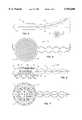
- FIG. 1Ais an exploded view of a wound covering according to the present invention
- FIG. 1Billustrates an assembled view of the wound covering of FIG. 1A
- FIG. 2Ais a view of an alternate wound covering
- FIG. 2Bis a view of an alternate wound covering of FIG. 2A with passive heating card inserted in the wound covering;
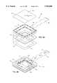
- FIG. 3Ais an exploded view of an additional alternate wound covering
- FIG. 3Bis an assembled view of the wound covering of FIG. 3A;
- FIG. 4is a side elevation view of a wound covering
- FIG. 5is an enlarged top plan view of a wound covering
- FIG. 6is an enlarged sectional view taken along line 6--6 of FIG. 5;
- FIG. 7is a bottom view of the wound covering of FIG. 4;
- FIG. 8Ais an exploded view of an alternate wound covering
- FIG. 8Bis an assembly view showing the air flow through the wound covering
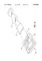
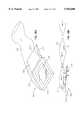
- FIG. 9Ais a perspective view of an alternate wound covering
- FIG. 9Bis a side view of the wound covering of FIG. 9A;
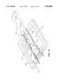
- FIG. 10is a perspective view of an alternate wound covering
- FIG. 11Ais a perspective view of an alternate wound covering
- FIG. 11Bis a side elevational view of the wound covering of FIG. 11A;
- FIG. 11Cis a view of the wound covering of FIG. 11A;
- FIG. 12is a perspective view of an alternate connector apparatus for the wound covering
- FIG. 13Ais an alternate connector arrangement for the wound covering
- FIG. 13Bis a side sectional view of the wound covering of FIG. 13A;
- FIG. 14is a view of a rigid connector for engagement with a wound covering
- FIG. 15is an alternate fluid inlet line for the wound covering
- FIG. 16Ais a view of a two ply barrier layer wound covering
- FIG. 16Bis a side elevational view of the wound covering of FIG. 16A;
- FIG. 17is an alternate wound covering
- FIG. 18Ais an alternate wound covering
- FIG. 18Bis a side sectional view of the wound covering of FIG. 18A;
- FIG. 19is a side elevational view of an alternate wound covering
- FIG. 20is a schematic diagram of an embodiment of the present invention.
- FIG. 21Ais a schematic representation of an alternate embodiment of the heater array distribution shown in FIG. 20;
- FIG. 21Bis a schematic representation of an alternate embodiment of the heater array distribution shown in FIGS. 20 and 21A;
- FIG. 21Cis a schematic representation of an alternate embodiment of the heater array distribution shown in FIGS. 20, 21A, and 21B;
- FIG. 21Dis a schematic representation of an alternate embodiment of the heater array distribution shown in FIGS. 20, 21A, 21B, and 21C;
- FIG. 22is a graphical representative sample of an operational scheme for an embodiment of the present invention, such as the embodiment shown in FIG. 20;
- FIG. 23is a graphical representative sample of an additional operational scheme for an embodiment of the present invention, such as the embodiment shown in FIG. 20 using the scheme depicted in FIG. 22;
- FIG. 24is a graphical representative sample of another additional operational scheme for an embodiment of the present invention, such as the embodiment shown in FIG. 20 using the schemes depicted in FIGS. 22 and 23.
- the present inventionis directed to a non-contact wound covering for controlling the local environment at a wound site on a patient.
- a wound siteincludes those portions of the patient's skin obviously definable as the wound area and the immediately adjacent periwound area as the selected treatment area of the wound site.
- the wound coveringprotects the wound from contamination by materials from the outside environment and also prevents the wound site from shedding contaminants into the local environment of the patient, i.e. the hospital room.
- the treatment volume formed over the wound sitecan be controlled to create an optimal healing environment.
- woundrefers generically to surgical incisions, ulcers, or other lesions or breaks in the skin.
- a substantially vertical wallis provided to encircle the selected treatment area on the surface of the patient's skin.
- This vertical wallprovides an upper surface to support a layer spanning this structure above the level of the wound and a lower surface suitable for attachment to the patient's skin.
- This structureis referred to throughout as an attachment or a peripheral sealing ring. Together these elements form a wound treatment volume between the layer and the surface of the selected treatment area.
- the fact that the layer does not contact the wound itselfpromotes healing by minimizing mechanical stresses on the tissues.
- the lower surface suitable for attaching to the skinmay include an adhesive and a complimentary release liner assembly to facilitate the attachment of the wound covering to the skin of the patient.
- the present inventionanticipates using a heater such that the layer may comprise the heater formed as the layer or as a layer which includes a heater within some portion of the layer.
- the layermay also include functioning as a barrier layer completely enclosing the wound treatment volume.
- the climate within the wound treatment volumemay be controlled.
- the temperature, humidity, and gas compositionfor example adding oxygen, nitric oxide or ozone, are controlled.
- aerosolized medications or compoundsmay be released into this volume as well.
- the above listis exemplary of the climate controls which may promote healing of the wound, and is not intended to limit the scope of the present invention. It will be understood by those skilled in the art that numerous other climate factors can be controlled within the treatment volume of the present wound covering system without departing from the scope of the invention.
- FIG. 1Aillustrates an exploded view of a wound covering 50.
- a peripheral sealing ring 52is substantially square in outline.
- Peripheral sealing ring 52is intended to be attached to uninjured skin surrounding a selected treatment area 54 using an adhesive 56.
- a layer of adhesive hydrogelis shown as the adhesive 56.
- peripheral sealing ring 52is preferably constructed of an open cell hydrophilic foam plastic having a sealed outer surface 58 which isolates the wound from the environment.
- the peripheral sealing ringis fabricated from a material which may conform to the curved surface of the patient's body.
- sealing ring 52is preferably porous or absorbent so that it can form a reservoir to contain and release moisture or water vapor into the air within a treatment volume 62 to create a high humidity environment if desired. Additionally, the hydrophilic absorbent nature of peripheral sealing ring 52 absorbs fluids and blood weeping from the wound.
- a layer 64is preferably attached to an upper surface 66 of peripheral sealing ring 52 as a barrier layer to seal treatment volume 62.
- Layer 64is preferably constructed of a flexible synthetic polymeric film, such as polyethylene, polyvinyl chloride, polyurethane, or polypropylene. Additionally, other polymeric films, natural and semisynthetic, that are suitable for use in medical applications such as cellulose and cellulose acetate, may be used.
- a wound tracing grid 68also constructed of a substantially clear flexible material, may optionally be used as, or attached to, layer 64 to facilitate wound care management so that the physician can draw an outline of the wound as an aid to tracking the healing process of the wound.
- the wound tracing gridpreferably contains a labeling area 70 for identifying the patient, date when the wound was traced, and other patient medical data.
- peripheral sealing ring 52will depend on the structural strength of the support material and the amount of fluid absorption desired. Additionally, the total area of peripheral sealing ring 52 is dependent on the size of the wound. For example, larger wounds and more flexible covers will require a thicker sealing ring so that the center of the cover does not touch the wound.
- peripheral sealing ring 52is preferably sealed by extending barrier layer 64 over the entire area of upper surface 66 as shown in FIGS. 1A and 1B.
- Adhesive 56 for attaching peripheral sealing ring 52 to uninjured skin surrounding selected treatment area 54may take any form, however, the preferred adhesive is preferably a two-faced hydrogel which attaches to a lower surface 72 of peripheral sealing ring 52. This adhesive 56 permits the attachment of peripheral sealing ring 52 to the patient's skin.
- peripheral sealing ring 52may serve as a reservoir for retaining water or medicaments in treatment volume 62 in order to maintain a high humidity in the air within the volume. Water may be added to peripheral sealing ring 52 at any time during treatment.
- peripheral sealing ring 52can be supplied in a variety of shapes and sizes to accommodate various wounds.
- the shapesmay include circles, squares, or rectangles.
- barrier layer 64 and wound tracing grid 68could be provided in large sheets which may be cut to size and then attached to the peripheral sealing ring.
- FIG. 1Bis an assembled view of wound covering 50 of FIG. 1A.
- a release liner 74 of FIG. 1Bis applied to adhesive 56 in FIG. 1A.
- Release liner 74may span the entire lower surface of the covering to maintain the sterility of treatment volume 62.
- Release liner 74preferably has a grip tab 76 to facilitate removal of release liner 74 from wound covering 50 immediately prior to application of wound covering 50 to the skin of a patient.
- FIGS. 2A and 2Billustrate an alternate embodiment of the present invention as a wound covering 80 utilizing passive heating of the treatment volume 62. Because heat is constantly being radiated from the patient's skin surface, the insulation properties of the trapped air within treatment volume 62 will reduce this heat loss. By adding an infrared reflector 82 over treatment volume 62, the infrared heat from the body can be reflected back to the skin for added passive heating.
- An edge 84 of wound tracing grid 86is preferably not attached to the barrier layer to form an envelope or a pocket 94 between the wound tracing grid 86 and the barrier layer.
- a piece of reflective foil material 88may be inserted into pocket 94.
- a thin layer of insulating material 90may be optionally attached to foil layer 88 to enhance heat retention and to provide foil layer 88 with additional resiliency.
- a tab 92is preferably attached to infrared reflector 82 to allow easy insertion and removal from pocket 94 and wound covering 80.
- FIGS. 3A and 3Billustrate a preferred alternate embodiment of a non-contact wound covering 108 utilizing active heating of a treatment volume 112. Wounds may be safely and easily heated utilizing a heater assembly 100.
- Heater assembly 100alternatively comprises a pressure-sensitive switch 102, an insulating layer 104, and a foil heater 106.
- Pressure-sensitive switch 102is optionally laminated to the upper surface of heater assembly 100.
- the purpose of switch 102is to shut off power to foil heater 106 in the event that external pressure is applied to wound covering 108 with sufficient force to cause foil heater 106 to contact the skin or wound below. This feature prevents the possibility of applying heat and pressure to the skin at the same time.
- the combination of heat and pressureis known to cause burns even at low temperatures (40° C.) because the pressure prevents blood flow in the skin making it susceptible to thermal injury.
- Pressure-sensitive switch 102preferably covers the entire area of heater assembly 100 so that pressure applied anywhere to the surface of heater assembly 100 will deactivate foil heater 106.
- An alternative safety feature anticipated by the present inventionis a monitoring function for detecting dramatic increases in power utilization by the heater trying to maintain an operating temperature.
- the heaterUnder normal operation, the heater is in a non-contact position proximate the selected treatment area and the heater will have been programmed to operate at a temperature that may be either a straight temperature value or an averaged value for either a duty cycle, therapy cycle or therapeutic sequence. If physical pressure is placed on the heater and it comes into contact with the patient's body, there will be a considerable increase in the rate of heat loss from the heater because of the body's greater heat sink capacity.
- the heater controllerwould sense this drop in temperature and initially adjust either the duty cycle ratio or power output, or both, in an attempt to compensate for the increase rate of loss.
- the safety aspect of this monitoring functionwould be to override this increase and turn off the device, thus preventing heating the tissue while in direct contact with, and under pressure from, the heater.
- Heater element 106is preferably a thin film type resistance heater which is commercially available. Such thin film resistance heaters utilize low voltage, minimizing the electrical risk to the patient and allowing for battery-powered mobility.
- Foil heater 106is preferably sized for each wound covering 108. In actual use, foil heater 106 is preferably provided in sheets with a pair of electrical leads 110 along one edge. While an electrical resistance heater is the preferred embodiment of the invention, other heating devices are anticipated such as warm water pads, exothermic chemical heating pads, and phase-change salt pads.
- Heater assembly 100is preferably insertable into a pocket 114 formed between wound tracing grid 86 and the barrier layer as discussed above.
- a temperature monitoring devicesuch as a liquid crystal temperature monitor, may be applied to an upper surface of heater assembly 100 or within treatment volume 112 to monitor the temperature within treatment volume 112.
- FIGS. 4-7illustrate an alternate embodiment of wound covering 10.
- wound covering 10includes a generally circular head, designated generally at 12, which transitions to an elongated non-kinking, collapsible air supply or hose 14.
- the apparatusas illustrated in FIG. 4, is connected by suitable supply line or tube 16 to a source 18 of thermally controlled air which is schematically illustrated.
- the term air as used hereinis intended to encompass mixtures of gases of controlled composition.
- the apparatusis constructed to apply a continuous stream of thermally controlled air to a wound treatment volume.
- FIG. 4 and FIG. 5The overall appearance of the wound covering is best seen in FIG. 4 and FIG. 5. It is preferred to construct the apparatus from top and bottom sheets of thin heat-sealable polymer film which overlay one another.
- a top sheet or membrane 20overlies a bottom sheet or membrane 22 which are heat sealed together along a plurality of seal lines, including a continuous outer seam 24, which extends in a circle around head 12 and continues in a sinusoidal or convoluted fashion along and forming hose 14.
- An inner continuous circular seam 26is provided as best seen in FIGS. 6 and 7. This inner seam 26 secures the sheets together along a continuous circle to form the inner wall of a torus defining a supply volume 28.
- Wall 30The inner circular portion of the two sheets 20, 22 lying in the plane within the center of the supply volume 28 forms a wall 30 separating a lower wound treatment volume 32 from an upper insulation chamber 34.
- Wall 30includes a plurality of apertures 36 formed by making small circular seals 38 and cutting and removing circular portions within the circular seals 38.
- wall 30, with a plurality of apertures 36is formed between the wound treatment volume 32 and insulation chamber 34.
- a plurality of apertures 40are formed in the common circular wall surrounding treatment volume 32 for distributing and conveying heated air or gases from supply volume 28 into wound treatment volume 32.
- the heated air flowing into treatment volume 32bathes the wound surface of a patient's body 42.
- the aircirculates throughout wound treatment volume 32, and then passes through apertures 36 into the upper or insulating chamber 34, where it then passes through a filter 44 forming an outer wall of insulation chamber 34.
- Filter 44filters the air leaving wound treatment volume 32, trapping contaminants shed from the wound.
- Filter 44may be constructed of a filter paper bonded along its periphery to the outer tangential walls of head 12 forming the torus.
- the filter paperalso provides an insulating layer which suppresses loss of heat by radiation through upper wall 30.
- the lower surface of the head 12 as shown in FIGS. 6 and 7is provided with a peripheral sealing ring 46 made of an absorbent material such as foam and bonded by a suitable adhesive to the walls of head 12 and skin 42 of the patient around the wound.
- foam or cotton peripheral sealing ring 46is provided with a peel-off tape so that it adheres to the wall of the housing and on the other side to the skin of the patient.
- the adhesive or tapeholds the apparatus in place and prevents airflow escape between the device and the skin of the patient.
- the absorbent material of the ringabsorbs weeping blood and fluids and insulates the skin from direct conduction of heat from head 12.
- Hose 14is designed to be non-kinking by forming it of symmetrically convoluted flexible material.
- the hose and housingare integrally formed essentially of a unitary structure, such as a thin film membrane.
- Hose 14is inflatable upon the application of heated air through supply line 16. The indentations in hose 14 permit it to bend without kinking and, thus, differentiate from a straight tubular hose which may kink when bent.
- the thermal body treatment apparatus of the invention and the supply hose sectionare formed from two, thin, sealed-together membranes, the hose, and in fact the entire apparatus, is collapsible. This prevents the possibility of applying heat and pressure to the skin as might happen if a patient rolled over on the device. Instead, the weight of the patient's body collapses the device, obstructing the flow of air, and preventing the application of heat.
- the film membranemay preferably be transparent to enable viewing the wound without removal. However for cosmetic reasons the layer may be opaque. Filter paper 44 is attached across the tangential surfaces of the toroidal housing, thus providing a large area of filter for the escaping air. Head 12 of the apparatus may be about one foot in diameter for most applications. However, it may be made smaller for certain other applications.
- FIG. 8Aillustrates an exploded view of an alternate embodiment of a non-contact wound covering 120 with climate control within a treatment volume 122 as shown in FIG. 8B.
- An inflatable structure 124is preferably attached to a fluid inlet line 126 at a fluid inlet port 129 on the perimeter of inflatable structure 124.
- Inflatable structure 124is preferably attached to an absorbent peripheral sealing ring 128, which is in turn attached to a wound area 54 by a suitable adhesive 56.
- Peripheral sealing ring 128preferably has a sealed outer surface and a porous inner surface which performs the same function as peripheral sealing ring 52 discussed above.
- a barrier layer 130 having an exhaust filter 132is attached to a top surface 134 on inflatable structure 124.
- a gasillustrated by direction arrows "A" is introduced into inflatable structure 124 from an external source (not shown) through inlet line 126.
- the gaspressurizes inflatable structure 124 in order to maintain barrier layer 130 and exhaust filter 132 in an elevated position relative to wound area 54.
- An inner surface 136 of inflatable structure 124preferably has a plurality of apertures 138 through which the fluid is introduced into wound treatment volume 122. As pressure within the treatment chamber increases, excess pressure is relieved through exhaust filter 132. In this fashion, various fluids or gases can be introduced into wound treatment volume 122.
- oxygenmay be introduced into treatment volume 122 through apertures 138 of inflatable structure 124.
- the presence of oxygen within wound treatment volume 122may increase the oxygen available to the superficial layer of growing cells in wound area 54.
- Nitric oxidealternatively may be infused into treatment volume 122.
- Nitric oxide (NO)is a potent vasodilator which in theory may be absorbed across the wound surface and increase localized blood flow. A very small concentration of NO (parts per million) may provide this effect. NO may also be pre-absorbed into absorbent peripheral sealing ring 128 and then allowed to passively diff-use into the volume once it is applied to the wound.
- gaseous or aerosolized medications or compoundsmay be introduced into the gas flow entering treatment volume 122.
- FIGS. 9A and 9Billustrate an alternate embodiment of the climate control system discussed above wherein a fluid inlet line 140 may form part of a barrier layer 142.
- Barrier layer 142is unitary with fluid inlet line 140 and is preferably attached to an exhaust filter media 144 to allow excess pressure to be released from a wound treatment volume 146.
- filter media 144forms part of barrier layer 142.
- the arrows "A" in FIG. 9Billustrate the movement of the fluid through fluid inlet line 140, treatment volume 146, and exhaust filter 144.
- FIG. 10illustrates an alternate embodiment wherein an exhaust filter 154 is retained in a recess 150 formed in one side of a peripheral sealing ring 152. This structure allows excess fluid to be exhausted through the side of peripheral sealing ring 152, rather than through the top, as illustrated in FIGS. 9A and 9B.
- FIG. 11Ais a perspective view of the embodiment illustrated in FIG. 9A, wherein a connector 160 on the end of a fluid supply line 162 engages with an opening 164 on fluid inlet line 140.
- FIG. 11 Billustrates a side view of fluid supply line 162 as it engages with fluid inlet line 140.
- FIG. 11Cillustrates the embodiment in FIGS. 11A and 11B where fluid inlet line 140 is folded over the top of peripheral sealing ring 152 to seal treatment volume 146 when supply line 162 is uncoupled.
- FIG. 12illustrates an alternate embodiment in which a fluid inlet slot 170 engages with a rigid connector 172 on a fluid inlet line 174.
- Fluid inlet slot 170forms an opening in one portion of a peripheral sealing ring 176. The opening is in fluid communication with a treatment volume 178. This configuration allows for quick disconnection of fluid inlet line 174 from wound covering 180 providing the patient with additional mobility.
- FIG. 13Ais a perspective view of an alternate non-contact wound covering 190 having a fluid inlet connector 192 attached to a top surface 194 of a peripheral sealing ring 196.
- Fluid inlet connector 192preferably contains an inlet filter media 198.
- a rigid connector 200 on a fluid inlet line 202mates with fluid inlet connector 192.
- a cover 204extends from the top of fluid inlet connector 192 across the top of peripheral sealing ring 196 where it engages with an exhaust filter media 206.
- FIG. 14illustrates the embodiment of FIGS. 13A and 13B utilizing a non-disposable fluid supply line 210.
- FIG. 15illustrates an alternate embodiment which utilizes a manifold structure 220 as part of a fluid inlet line 222 to provide even distribution of the fluid being introduced into a treatment volume 224.
- Fluid inlet line 222preferably has a series of seals 226 along its edge which are interrupted by a plurality of side openings 228 from which the fluid can be transmitted into treatment volume 224.
- the embodiment disclosed in FIG. 15illustrates an exhaust filter 230 recessed into the side of peripheral sealing ring 232.
- exhaust filter configurationsare possible with the disclosed manifold structure 220.
- FIGS. 16A and 16Billustrate an alternate wound covering 240 with a top barrier layer 242 and a lower layer 244 having a plurality of holes 246.
- a top cover 243forms the barrier layer 242 and it extends substantially across the area of the peripheral sealing ring 248.
- Lower layer 244likewise extends across the peripheral sealing ring 248.
- an upper insulating layer 250is formed between lower layer 244 and the top of barrier layer 242.
- Fluid in a fluid inlet line 252is directed into upper insulating layer 250.
- the pressurized fluid in upper insulating layer 250passes through holes 246 into a treatment volume 254. Holes 246 in lower layer 244 provide a generally even distribution of the fluid within wound treatment volume 254.
- An optional seal 258may be formed in the center portion of barrier layer 242 and lower layer 244 to provide these layers with additional structural support.
- An exhaust filter medium 256is provided in a recess along one side of peripheral sealing ring 248 to relieve pressure in treatment volume 254.
- FIG. 17illustrates an alternate embodiment of a non-contact wound covering 260 utilizing semi-rigid supports 262 to retain a barrier layer 264 above a wound area.
- semi-rigid supports 262may be utilized for this application.
- plastic or resilient rubber materialsmay provide sufficient support to barrier layer 264 with a minimum risk of injuring the patient.
- FIGS. 18A and 18Billustrate an alternate exhaust filter medium 270 with an enlarged surface area to accommodate larger volumes of air flow through a non-contact wound covering 280.
- Exhaust filter 270is incorporated into a fluid inlet line 272.
- Fluid inlet line 272also forms a portion of a barrier layer 274, which is in turn attached to a peripheral sealing ring 276.
- fluid illustrated as the arrows "A"is introduced into a fluid inlet line 272, where it is directed into a wound treatment volume 278, past the wound area and out through exhaust filter medium 270.
- FIG. 19illustrates a bi-directional line 290 with a center divider 292. Fluid is introduced into a fluid inlet line 294 where it proceeds through a fluid inlet port 296 into a treatment volume 298. The fluid then is forced through a fluid outlet port 300 where it is driven away from treatment volume 298 in a fluid outlet line 302. It will be understood by those skilled in the art that it would be possible to utilize separate fluid inlet and outlet lines to achieve the same result.
- FIG. 20A schematic diagram of an embodiment of the present invention using active heating and control is depicted in FIG. 20 as an active heater assembly 310 including a heater 312, a heater filament 314 within heater 312, a controller 316, electrically coupled between heater filament 314 and a power source 318 by electrical connectors 315, and using a heater temperature sensor 320, and an operator interface 322 suitable for an operator to input programming parameters into controller 316.
- Heater assembly 310is useful in several different configurations, for example, as providing a heater layer for use directly in a pocket such as that depicted by heater 100 inserted into pocket 114 shown in FIGS. 3A and 3B or as a heat source for warmning air that is circulated proximate the wound as is depicted in the several embodiments of FIGS. 4 through 19.
- FIGS. 21A, B, C, and Dwherein there is depicted additional alternate heater array geometries for heating filament 314 within heater 312.
- FIG. 21Athere is depicted a linear geometry for heater filament 314. This geometry is suitable for non-uniform heating where maximum heating is desired over a linear area, such as a linear surgical wound without direct heating over adjacent periwound areas.
- FIG. 21Bdepicts a geometry for heater filament 314 consistent more as a point source.
- 21Cdepicts an ovoid geometry for filament 314 suitable for non-uniform heating of selected periwound area.
- this non-uniform heatingmay be achievable with circular, square, rectangular, triangular or other such geometries depending on the type and shape of wound encountered.
- heater assembly 310is programmable, controlling several parameters, such as heater temperature, duty cycle, therapy cycle, number of duty cycles per therapy cycle, average heater temperature per duty cycle, average heater temperature per therapy cycle, peak and minimum heater temperatures per heater cycle, and peak and minimum heater temperatures for a therapy cycle.
- the programmingmay be preset at time of manufacture and may provide a menu of several treatment scenarios. Additionally, the parameter programmability may be entirely under the control of an operator and suitable for inputting any number of custom treatment regimens.
- FIG. 22is a graphic representation of one such therapy cycle represented by several heater and duty cycles.
- several duty cycleshave been defined within a therapy cycle where time (t) is represented along the abscissa and heater temperature (T) along the ordinate.
- time (t)is represented along the abscissa and heater temperature (T) along the ordinate.
- Theater temperature
- the heateris at ambient temperature T amb 332 and the first of several duty cycles begins at t 0 330 by turning on the heater to heat up to a temperature at about T peak 334.
- T peak 334Upon reaching T peak 334 by t 1 336, the heater power is turned off and the heater cools to T min 338.
- the first duty cycleis completed at t 1 336 when the heater is turned off.
- the first heater cycleis completed at t 2 340 when the heater is turned back on to begin the next duty and heater cycle.
- This first heater cycle and subsequent heater cyclesmaintain an average heater temperature T set 342.
- the duty cycleis given by the ratio of the duration of t 0 -t 1 over t 0 -t 2 .
- Those familiar with the art of heater activity controlwill appreciate there are a variety of methods for manipulating heater activity, including proportional action controllers using processor logic to maximize heater action and control.
- a therapy cycle for this exampleis the time duration from t 0 330 to t t 344 during which time the heater temperature has been allowed to fall to T amb 332, where at t t 344 the heating regimen begins again starting the next therapy cycle.
- a peak temperature, T peak 334may be the parameter inputted into the program.
- this rangeis preferably from above 38° C. to about 46° C.
- the present inventionanticipates alternative selections of temperatures inputted for the operating temperature.
- a first alternativeis to establish an average heater cycle temperature. In FIG. 22, this concept is represented by T set 342.
- this average heater cycle temperaturewould have the same range, from above 38° C. to about 46° C.
- the temperature selectionmay be inputted as a T peak 334 and a T min 338, both temperatures selected from the same range.
- FIG. 23a plurality of therapy cycles are depicted in FIG. 23, wherein individual heater cycles within each therapy cycle have been averaged out for purposes of clarification and for purposes herein are treated as the heater being "on".
- a first therapy cyclebegins at to 350 as depicted by the heater turning "on”, i.e., a series of heater cycles is begun, and the heater heats to T set 352. This "on” segment goes until t 1 354 at which time the heater is turned “off” and allowed to cool to T amb 356.
- This first therapy cycleends at t 2 358 when a second therapy begins by turning "on” the heater again.
- this second therapy cycleheats to T set 352 and has a duration from t 2 358 to t 3 360.
- a third therapy cyclebegins at t 3 360 turning "on" the heater.
- this third therapy cycleis given a different T set 362.
- the heateris turned “off” at t 4 364.
- This entire period of multiple therapy cyclesmay also be part of a therapeutic sequence, depicted in FIG. 23 as that period of time from t 0 350 to t t 366 encompassing three therapy cycles.
- the present inventionanticipates the use of any number of therapy cycles having any length or duration per cycle and different set temperatures.
- FIG. 24Another aspect of heater therapy control, averaging therapy cycle and therapeutic sequence temperatures, is depicted in FIG. 24 as an additional example, the example not intended to be limiting in scope of treatment versatility.
- a therapy cyclestarts at t 0 370 and ends at t 1 372.
- the overall heater temperature average T ave 374 for this therapy cyclemay be pre-selected or programmed.
- the heaterbeginning at an ambient temperature T amb 376, heats to an appropriate temperature for the "on” phase and then is "off” for an additional appropriate time such that the total period of time is equivalent to the period t 0 370 to t 1 372 and the average temperature for this period is equivalent to T ave 374.
- An alternative approachanticipates the programming of a number of therapy cycles as elements of a therapeutic sequence, in this example there being three therapy cycles of varying time and heater temperature.
- the present invention versatilityprovides for the inputting of an average temperature T ave 378 for the therapeutic sequence.
- the therapeutic sequencebegins at time t 0 370 and ends at time t t 380.
- the heater temperatures and durations of the therapy cycles within the therapeutic sequenceare averaged by the controller over the entire period of time from t 0 370 to t t 380 so as to achieve the therapeutic average temperature T ave 378.
- Each of these average temperatureswhether an average over a therapy cycle or over a therapeutic sequence, is intended to have the same temperature range from above 38°0 C. to about 46° C.
- a secondary consequence of this controller regimenis that if average temperatures are used, either over the therapy cycle and/or therapeutic sequence, then the resultant peak temperatures achieved by the heater may be substantially higher than the 38° C. to about 46° C. range. These peak temperatures are short lived by comparison and do not represent a safety concern.
- the present inventionis the development of a safe, efficacious non-contact heater wound covering providing heat to a patient's wound from the heater that is in a temperature range from above 38° C. to about 46° C. or controlled to an average temperature range from above 38° C. to about 46° C.
Landscapes
- Health & Medical Sciences (AREA)
- Heart & Thoracic Surgery (AREA)
- Animal Behavior & Ethology (AREA)
- Veterinary Medicine (AREA)
- Biomedical Technology (AREA)
- Engineering & Computer Science (AREA)
- Public Health (AREA)
- Life Sciences & Earth Sciences (AREA)
- General Health & Medical Sciences (AREA)
- Vascular Medicine (AREA)
- Anesthesiology (AREA)
- Hematology (AREA)
- Physics & Mathematics (AREA)
- Thermal Sciences (AREA)
- Oral & Maxillofacial Surgery (AREA)
- Pulmonology (AREA)
- Surgery (AREA)
- Thermotherapy And Cooling Therapy Devices (AREA)
- Resistance Heating (AREA)
Abstract
Description
______________________________________ Average Maximum______________________________________Normally perfusedhuman skin 36° C. 36° C.Arterial/diabetic foot ulcers 32° C. 35° C.Venous/arterial leg/foot ulcers 33° C. 35° C.Non-perfused human model 35° C. 35° C.______________________________________
TABLE 1______________________________________Time Subcutaneous Temperature(in minutes) (° C. mean ± S.D.)______________________________________-60 33.9 ± 1.1 0 34.7 ± 1.2 30 36.9 ± 0.6 60 37.1 ± 0.4 90 37.4 ± 0.5120 37.6 ± 0.5180 36.0 ± 0.4240 36.1 ± 0.2300 35.8 ± 0.6______________________________________
TABLE 2______________________________________Time Skin Temperature Inside Covering(in minutes) (° C. mean ± S.D.)______________________________________-60 33.2 ± 1.1 0 33.9 ± 1.1 30 36.7 ± 0.5 60 37.0 ± 0.4 90 37.1 ± 0.4120 37.2 ± 0.4180 35.2 ± 0.5240 35.2 ± 0.4300 35.1 ± 0.5______________________________________
TABLE 3______________________________________Time Laser Doppler Flow(in minutes) (ml/100 g/min mean ± S.D.)______________________________________-60 64 ± 42 0 110 ± 100 30 199 ± 191 60 178 ± 131 90 222 ± 143120 271 ± 235180 158 ± 146240 146 ± 125300 173 ± 158______________________________________
TABLE 4______________________________________Time Subcutaneous Oxygen Tension (P.sub.sq O.sub.2)(in minutes) (mm Hg mean ± S.D.)______________________________________-60 54 ± 10 0 110 ± 60 30 109 ± 58 60 122 ± 59 90 136 ± 57120 159 ± 55180 153 ± 60240 156 ± 61300 148 ± 52______________________________________
TABLE 5______________________________________Time Subcutaneous Temperature(in minutes) (° C.)______________________________________-60 33.8 ± 1.5 0 35.2 ± 1.5 30 37.1 ± 1.1 60 37.3 ± 0.8 90 37.4 ± 0.7120 37.3 ± 0.8180 35.8 ± 1.2240 35.8 ± 1.0300 36.1 ± 0.9______________________________________
TABLE 6______________________________________Time Skin Temperature Inside Covering(in minutes) (° C.)______________________________________-60 32.9 ± 1.5 0 34.5 ± 1.0 30 37.1 ± 0.6 60 37.5 ± 0.5 90 37.6 ± 0.5120 37.6 ± 0.5180 34.9 ± 0.8240 35.0 ± 0.7300 35.2 ± 0.6______________________________________
TABLE 7______________________________________Time Laser Doppler Flow(in minutes) (mg/100 g/min)______________________________________-60 44 ± 22 0 95 ± 132 30 142 ± 155 60 191 ± 150 90 207 ± 209120 161 ± 91180 73 ± 29240 70 ± 30300 71.5 ± 25______________________________________
TABLE 8______________________________________Time Subcutaneous Oxygen Tension (P.sub.sq O.sub.2)(in minutes) (mm Hg)______________________________________-60 58 ± 11 0 123 ± 73 30 128 ± 67 60 145 ± 69 90 157 ± 73120 153 ± 55180 148 ± 73240 142 ± 73300 143 ± 76______________________________________
Claims (49)
Priority Applications (11)
| Application Number | Priority Date | Filing Date | Title |
|---|---|---|---|
| US08/786,714US5954680A (en) | 1992-06-19 | 1997-01-21 | Near hyperthermic heater wound covering |
| EP97948340AEP0954263B1 (en) | 1997-01-21 | 1997-11-12 | Near hyperthermic heater wound covering |
| PCT/US1997/021013WO1998031311A1 (en) | 1997-01-21 | 1997-11-12 | Near hyperthermic heater wound covering |
| DE69703749TDE69703749T2 (en) | 1997-01-21 | 1997-11-12 | HEATED WATER COVER WITH SLIGHTLY HYPERTHERMAL PROPERTY |
| AT97948340TATE198136T1 (en) | 1997-01-21 | 1997-11-12 | HEATED WOUND COVER WITH SLIGHTLY HYPERTHERMAL PROPERTIES |
| AU54426/98AAU721971B2 (en) | 1997-01-21 | 1997-11-12 | Near hyperthermic heater wound covering |
| CA002271031ACA2271031C (en) | 1997-01-21 | 1997-11-12 | Near hyperthermic heater wound covering |
| US09/272,028US6071254A (en) | 1992-06-19 | 1999-03-18 | Near hyperthermic heater wound covering |
| US09/491,921US6241698B1 (en) | 1992-06-19 | 2000-01-27 | Near hyperthermic heater wound covering |
| US09/771,792US6407307B1 (en) | 1993-06-18 | 2001-01-29 | Near hyperthermic heater covering |
| US10/160,278US6605051B2 (en) | 1992-06-19 | 2002-05-31 | Near hyperthermic tissue treatment |
Applications Claiming Priority (2)
| Application Number | Priority Date | Filing Date | Title |
|---|---|---|---|
| US90065692A | 1992-06-19 | 1992-06-19 | |
| US08/786,714US5954680A (en) | 1992-06-19 | 1997-01-21 | Near hyperthermic heater wound covering |
Related Parent Applications (4)
| Application Number | Title | Priority Date | Filing Date |
|---|---|---|---|
| US08356325Continuation-In-Part | 1993-06-18 | ||
| PCT/US1993/005876Continuation-In-PartWO1994000090A2 (en) | 1992-06-19 | 1993-06-18 | Wound covering |
| US08356325Continuation-In-Part | 1994-12-16 | ||
| US35632595AContinuation-In-Part | 1992-06-19 | 1995-02-21 |
Related Child Applications (2)
| Application Number | Title | Priority Date | Filing Date |
|---|---|---|---|
| US09/272,028DivisionUS6071254A (en) | 1992-06-19 | 1999-03-18 | Near hyperthermic heater wound covering |
| US09/272,028ContinuationUS6071254A (en) | 1992-06-19 | 1999-03-18 | Near hyperthermic heater wound covering |
Publications (1)
| Publication Number | Publication Date |
|---|---|
| US5954680Atrue US5954680A (en) | 1999-09-21 |
Family
ID=25139396
Family Applications (5)
| Application Number | Title | Priority Date | Filing Date |
|---|---|---|---|
| US08/786,714Expired - LifetimeUS5954680A (en) | 1992-06-19 | 1997-01-21 | Near hyperthermic heater wound covering |
| US09/272,028Expired - Fee RelatedUS6071254A (en) | 1992-06-19 | 1999-03-18 | Near hyperthermic heater wound covering |
| US09/491,921Expired - LifetimeUS6241698B1 (en) | 1992-06-19 | 2000-01-27 | Near hyperthermic heater wound covering |
| US09/771,792Expired - Fee RelatedUS6407307B1 (en) | 1992-06-19 | 2001-01-29 | Near hyperthermic heater covering |
| US10/160,278Expired - Fee RelatedUS6605051B2 (en) | 1992-06-19 | 2002-05-31 | Near hyperthermic tissue treatment |
Family Applications After (4)
| Application Number | Title | Priority Date | Filing Date |
|---|---|---|---|
| US09/272,028Expired - Fee RelatedUS6071254A (en) | 1992-06-19 | 1999-03-18 | Near hyperthermic heater wound covering |
| US09/491,921Expired - LifetimeUS6241698B1 (en) | 1992-06-19 | 2000-01-27 | Near hyperthermic heater wound covering |
| US09/771,792Expired - Fee RelatedUS6407307B1 (en) | 1992-06-19 | 2001-01-29 | Near hyperthermic heater covering |
| US10/160,278Expired - Fee RelatedUS6605051B2 (en) | 1992-06-19 | 2002-05-31 | Near hyperthermic tissue treatment |
Country Status (7)
| Country | Link |
|---|---|
| US (5) | US5954680A (en) |
| EP (1) | EP0954263B1 (en) |
| AT (1) | ATE198136T1 (en) |
| AU (1) | AU721971B2 (en) |
| CA (1) | CA2271031C (en) |
| DE (1) | DE69703749T2 (en) |
| WO (1) | WO1998031311A1 (en) |
Cited By (104)
| Publication number | Priority date | Publication date | Assignee | Title |
|---|---|---|---|---|
| US6095992A (en)* | 1998-04-06 | 2000-08-01 | Augustine Medical, Inc. | Wound treatment apparatus for normothermic treatment of wounds |
| US6241698B1 (en)* | 1992-06-19 | 2001-06-05 | Augustine Medical, Inc. | Near hyperthermic heater wound covering |
| US6245096B1 (en)* | 1999-08-30 | 2001-06-12 | Respiratory Support Products, Inc. | Thermal cover member for delivering fluid to a patient |
| US6312403B1 (en)* | 1999-08-23 | 2001-11-06 | Luis Antonio Ruiz | Eye dryer, eye dryer system and method of using the same |
| US6336935B1 (en)* | 1999-09-15 | 2002-01-08 | The Procter & Gamble Company | Disposable thermal body wrap |
| US6458109B1 (en) | 1998-08-07 | 2002-10-01 | Hill-Rom Services, Inc. | Wound treatment apparatus |
| US20020169406A1 (en)* | 2001-05-10 | 2002-11-14 | Donald Stapf | Minimal contact treatment device |
| US20030069529A1 (en)* | 1994-11-21 | 2003-04-10 | Augustine Scott D. | Flexible non-contact wound treatment device |
| US6585670B2 (en) | 1998-04-06 | 2003-07-01 | Augustine Medical, Inc. | Treatment apparatus with a heater adhesively joined to a bandage |
| US6685681B2 (en) | 2000-11-29 | 2004-02-03 | Hill-Rom Services, Inc. | Vacuum therapy and cleansing dressing for wounds |
| US6755807B2 (en) | 1999-11-29 | 2004-06-29 | Hill-Rom Services, Inc. | Wound treatment apparatus |
| US6855135B2 (en) | 2000-11-29 | 2005-02-15 | Hill-Rom Services, Inc. | Vacuum therapy and cleansing dressing for wounds |
| US20050143794A1 (en)* | 2003-12-30 | 2005-06-30 | Hsiao Fu Yuan | Sap adjuster |
| US7008445B2 (en) | 2002-04-29 | 2006-03-07 | Medcool, Inc. | Method and device for rapidly inducing hypothermia |
| US7022113B2 (en) | 2001-07-12 | 2006-04-04 | Hill-Rom Services, Inc. | Control of vacuum level rate of change |
| US7052509B2 (en) | 2002-04-29 | 2006-05-30 | Medcool, Inc. | Method and device for rapidly inducing and then maintaining hypothermia |
| US20060178608A1 (en)* | 1999-11-10 | 2006-08-10 | Stapf Donald E | Tissue treatment device for an extremity |
| US20060235347A1 (en)* | 2005-04-16 | 2006-10-19 | Adel Aali | Deformable and conformable wound protecting apparatus and its method of application |
| US7195624B2 (en) | 2001-12-26 | 2007-03-27 | Hill-Rom Services, Inc. | Vented vacuum bandage with irrigation for wound healing and method |
| US20070129707A1 (en)* | 2003-10-28 | 2007-06-07 | Blott Patrick L | Wound cleansing apparatus with heat |
| US20070142761A1 (en)* | 2005-12-15 | 2007-06-21 | Adel Aali | Wound shield |
| US20070142757A1 (en)* | 2005-12-15 | 2007-06-21 | Adel Aali | Wound shield and warming apparatus and method |
| US20070161938A1 (en)* | 2006-01-12 | 2007-07-12 | Adel Aali | Dressing substrate |
| US20070191754A1 (en)* | 2006-02-13 | 2007-08-16 | Adel Aali | Wound shield |
| US7338482B2 (en) | 2002-02-28 | 2008-03-04 | Hill-Rom Services, Inc. | External catheter access to vacuum bandage |
| US20080294161A1 (en)* | 2007-05-25 | 2008-11-27 | Wolf Jr Stuart | Electrical cautery device |
| USD582047S1 (en)* | 2006-04-07 | 2008-12-02 | Heatmax, Inc. | Capsule warmer |
| USD583479S1 (en)* | 2007-02-12 | 2008-12-23 | Heatmax, Inc. | Personal warming apparatus |
| USD583959S1 (en)* | 2006-04-07 | 2008-12-30 | Heatmax, Inc. | Crescent warmer |
| US20090062710A1 (en)* | 2007-09-02 | 2009-03-05 | Lin Yu-Ho | Solid and painless sticking bar |
| US20090069759A1 (en)* | 2004-04-27 | 2009-03-12 | Smith & Nephew , Plc. | Apparatus for cleansing wounds with means for supply of thermal energy to the therapy fluid |
| US7534927B2 (en) | 2001-12-26 | 2009-05-19 | Hill-Rom Services, Inc. | Vacuum bandage packing |
| US20090173340A1 (en)* | 2007-05-24 | 2009-07-09 | Embrace Llc | Method and Apparatus to Relieve Menstrual Pain |
| US7678090B2 (en) | 1999-11-29 | 2010-03-16 | Risk Jr James R | Wound treatment apparatus |
| US7723560B2 (en) | 2001-12-26 | 2010-05-25 | Lockwood Jeffrey S | Wound vacuum therapy dressing kit |
| US7763000B2 (en) | 1999-11-29 | 2010-07-27 | Risk Jr James R | Wound treatment apparatus having a display |
| US20100211031A1 (en)* | 2007-07-02 | 2010-08-19 | Edward Hartwell | Wound treatment apparatus with exudate volume reduction by heat |
| US20100262094A1 (en)* | 2007-11-21 | 2010-10-14 | T.J. Smith & Nephew, Limited | Suction device and dressing |
| US20100312159A1 (en)* | 2005-04-16 | 2010-12-09 | Adel Aali | Secondary Wound Dressings for Securing Primary Dressings and Managing Fluid from Wounds, and Methods of Using Same |
| US20110015708A1 (en)* | 2007-05-24 | 2011-01-20 | Embrace, Llc | Method and apparatus to relieve menstrual pain |
| US20110015557A1 (en)* | 2009-07-16 | 2011-01-20 | Aalnex, Inc. | Systems And Methods For Protecting Incisions |
| US20110041839A1 (en)* | 2007-05-24 | 2011-02-24 | Embrace, Llc | Compression undergarment for relief of menstrual pain and related method of use |
| US7896856B2 (en) | 2002-08-21 | 2011-03-01 | Robert Petrosenko | Wound packing for preventing wound closure |
| US7910791B2 (en) | 2000-05-22 | 2011-03-22 | Coffey Arthur C | Combination SIS and vacuum bandage and method |
| US7928281B2 (en) | 1992-06-19 | 2011-04-19 | Arizant Technologies Llc | Wound covering |
| US7927318B2 (en) | 2001-10-11 | 2011-04-19 | Risk Jr James Robert | Waste container for negative pressure therapy |
| US7931651B2 (en) | 2006-11-17 | 2011-04-26 | Wake Lake University Health Sciences | External fixation assembly and method of use |
| US8067662B2 (en) | 2009-04-01 | 2011-11-29 | Aalnex, Inc. | Systems and methods for wound protection and exudate management |
| US20110306943A1 (en)* | 2005-02-08 | 2011-12-15 | Carewave, Inc. | Apparatus and method for using a portable thermal device to reduce accommodation of nerve receptors |
| US8168848B2 (en) | 2002-04-10 | 2012-05-01 | KCI Medical Resources, Inc. | Access openings in vacuum bandage |
| US20120232621A1 (en)* | 2011-03-10 | 2012-09-13 | Kriksunov Leo B | Thermal treatment device with variable heat distribution |
| US8267960B2 (en) | 2008-01-09 | 2012-09-18 | Wake Forest University Health Sciences | Device and method for treating central nervous system pathology |
| US8377016B2 (en) | 2007-01-10 | 2013-02-19 | Wake Forest University Health Sciences | Apparatus and method for wound treatment employing periodic sub-atmospheric pressure |
| US8398614B2 (en) | 2002-10-28 | 2013-03-19 | Smith & Nephew Plc | Apparatus for aspirating, irrigating and cleansing wounds |
| US8449509B2 (en) | 2004-04-05 | 2013-05-28 | Bluesky Medical Group Incorporated | Flexible reduced pressure treatment appliance |
| US8454671B2 (en) | 2002-12-12 | 2013-06-04 | Medcool, Inc. | Method and apparatus for reducing body temperature of a subject |
| US8529613B2 (en) | 2006-10-18 | 2013-09-10 | Medcool, Inc. | Adjustable thermal cap |
| US8529548B2 (en) | 2004-04-27 | 2013-09-10 | Smith & Nephew Plc | Wound treatment apparatus and method |
| US20130253494A1 (en)* | 2002-03-15 | 2013-09-26 | The General Hospital Corporation | Systems for removing heat from subcutaneous lipid-rich cells and systems for removing heat from a target tissue mass |
| US8834520B2 (en) | 2007-10-10 | 2014-09-16 | Wake Forest University | Devices and methods for treating spinal cord tissue |
| US9044569B2 (en) | 2004-04-28 | 2015-06-02 | Smith & Nephew Plc | Wound dressing apparatus and method of use |
| US9107753B2 (en) | 2007-05-24 | 2015-08-18 | Ziivaa Ip, Llc | Method to relieve menstrual pain |
| US9289193B2 (en) | 2008-07-18 | 2016-03-22 | Wake Forest University Health Sciences | Apparatus and method for cardiac tissue modulation by topical application of vacuum to minimize cell death and damage |
| US9314368B2 (en) | 2010-01-25 | 2016-04-19 | Zeltiq Aesthetics, Inc. | Home-use applicators for non-invasively removing heat from subcutaneous lipid-rich cells via phase change coolants, and associates devices, systems and methods |
| US9375345B2 (en) | 2006-09-26 | 2016-06-28 | Zeltiq Aesthetics, Inc. | Cooling device having a plurality of controllable cooling elements to provide a predetermined cooling profile |
| US9408745B2 (en) | 2007-08-21 | 2016-08-09 | Zeltiq Aesthetics, Inc. | Monitoring the cooling of subcutaneous lipid-rich cells, such as the cooling of adipose tissue |
| US9545523B2 (en) | 2013-03-14 | 2017-01-17 | Zeltiq Aesthetics, Inc. | Multi-modality treatment systems, methods and apparatus for altering subcutaneous lipid-rich tissue |
| USD777338S1 (en) | 2014-03-20 | 2017-01-24 | Zeltiq Aesthetics, Inc. | Cryotherapy applicator for cooling tissue |
| US9655770B2 (en) | 2007-07-13 | 2017-05-23 | Zeltiq Aesthetics, Inc. | System for treating lipid-rich regions |
| US9737434B2 (en) | 2008-12-17 | 2017-08-22 | Zeltiq Aestehtics, Inc. | Systems and methods with interrupt/resume capabilities for treating subcutaneous lipid-rich cells |
| US9844460B2 (en) | 2013-03-14 | 2017-12-19 | Zeltiq Aesthetics, Inc. | Treatment systems with fluid mixing systems and fluid-cooled applicators and methods of using the same |
| US9861520B2 (en) | 2009-04-30 | 2018-01-09 | Zeltiq Aesthetics, Inc. | Device, system and method of removing heat from subcutaneous lipid-rich cells |
| US9861421B2 (en) | 2014-01-31 | 2018-01-09 | Zeltiq Aesthetics, Inc. | Compositions, treatment systems and methods for improved cooling of lipid-rich tissue |
| US9937072B2 (en) | 2007-12-07 | 2018-04-10 | Carewave Medical, Inc. | Devices and methods for therapeutic heat treatment |
| US10010658B2 (en) | 2013-05-10 | 2018-07-03 | Smith & Nephew Plc | Fluidic connector for irrigation and aspiration of wounds |
| US10058642B2 (en) | 2004-04-05 | 2018-08-28 | Bluesky Medical Group Incorporated | Reduced pressure treatment system |
| US10092346B2 (en) | 2010-07-20 | 2018-10-09 | Zeltiq Aesthetics, Inc. | Combined modality treatment systems, methods and apparatus for body contouring applications |
| US20190060126A1 (en)* | 2017-08-30 | 2019-02-28 | Hill-Rom Services, Inc. | Systems for monitoring wounds and wound dressing status and systems for protecting wounds |
| US10342729B2 (en) | 2004-04-27 | 2019-07-09 | Smith & Nephew Plc | Wound cleansing apparatus with stress |
| US10383787B2 (en) | 2007-05-18 | 2019-08-20 | Zeltiq Aesthetics, Inc. | Treatment apparatus for removing heat from subcutaneous lipid-rich cells and massaging tissue |
| US10413644B2 (en) | 2004-04-27 | 2019-09-17 | Smith & Nephew Plc | Wound treatment apparatus and method |
| US10524956B2 (en) | 2016-01-07 | 2020-01-07 | Zeltiq Aesthetics, Inc. | Temperature-dependent adhesion between applicator and skin during cooling of tissue |
| US10555831B2 (en) | 2016-05-10 | 2020-02-11 | Zeltiq Aesthetics, Inc. | Hydrogel substances and methods of cryotherapy |
| US10568759B2 (en) | 2014-08-19 | 2020-02-25 | Zeltiq Aesthetics, Inc. | Treatment systems, small volume applicators, and methods for treating submental tissue |
| US10583228B2 (en) | 2015-07-28 | 2020-03-10 | J&M Shuler Medical, Inc. | Sub-atmospheric wound therapy systems and methods |
| US10596041B2 (en) | 2014-08-28 | 2020-03-24 | Ascension Texas | Apparatuses and methods for minimizing wound dehiscence, scar spread, and/or the like |
| US10675176B1 (en) | 2014-03-19 | 2020-06-09 | Zeltiq Aesthetics, Inc. | Treatment systems, devices, and methods for cooling targeted tissue |
| US10682297B2 (en) | 2016-05-10 | 2020-06-16 | Zeltiq Aesthetics, Inc. | Liposomes, emulsions, and methods for cryotherapy |
| US10722395B2 (en) | 2011-01-25 | 2020-07-28 | Zeltiq Aesthetics, Inc. | Devices, application systems and methods with localized heat flux zones for removing heat from subcutaneous lipid-rich cells |
| US10765552B2 (en) | 2016-02-18 | 2020-09-08 | Zeltiq Aesthetics, Inc. | Cooling cup applicators with contoured heads and liner assemblies |
| US10935174B2 (en) | 2014-08-19 | 2021-03-02 | Zeltiq Aesthetics, Inc. | Stress relief couplings for cryotherapy apparatuses |
| US10952891B1 (en) | 2014-05-13 | 2021-03-23 | Zeltiq Aesthetics, Inc. | Treatment systems with adjustable gap applicators and methods for cooling tissue |
| US11076879B2 (en) | 2017-04-26 | 2021-08-03 | Zeltiq Aesthetics, Inc. | Shallow surface cryotherapy applicators and related technology |
| US11154418B2 (en) | 2015-10-19 | 2021-10-26 | Zeltiq Aesthetics, Inc. | Vascular treatment systems, cooling devices, and methods for cooling vascular structures |
| US11160917B2 (en) | 2020-01-22 | 2021-11-02 | J&M Shuler Medical Inc. | Negative pressure wound therapy barrier |
| US20220016246A1 (en)* | 2013-09-11 | 2022-01-20 | Glenn Abrahmsohn | Hypertonic antimicrobial therapeutic compositions |
| US11298453B2 (en) | 2003-10-28 | 2022-04-12 | Smith & Nephew Plc | Apparatus and method for wound cleansing with actives |
| US11382790B2 (en) | 2016-05-10 | 2022-07-12 | Zeltiq Aesthetics, Inc. | Skin freezing systems for treating acne and skin conditions |
| US11395760B2 (en) | 2006-09-26 | 2022-07-26 | Zeltiq Aesthetics, Inc. | Tissue treatment methods |
| US11446175B2 (en) | 2018-07-31 | 2022-09-20 | Zeltiq Aesthetics, Inc. | Methods, devices, and systems for improving skin characteristics |
| US11590020B2 (en) | 2002-03-15 | 2023-02-28 | The General Hospital Corporation | Methods and devices for selective disruption of fatty tissue by controlled cooling |
| US11986421B2 (en) | 2006-09-26 | 2024-05-21 | Zeltiq Aesthetics, Inc. | Cooling devices with flexible sensors |
| US12070411B2 (en) | 2006-04-28 | 2024-08-27 | Zeltiq Aesthetics, Inc. | Cryoprotectant for use with a treatment device for improved cooling of subcutaneous lipid-rich cells |
| US12296129B2 (en) | 2018-03-07 | 2025-05-13 | Soovu Labs, Inc. | Systems and methods for improved pain relief from stimulation of thermal fibers |
Families Citing this family (51)
| Publication number | Priority date | Publication date | Assignee | Title |
|---|---|---|---|---|
| US20070086954A1 (en)* | 1998-11-23 | 2007-04-19 | Miller Christopher C | Method and apparatus for treatment of respiratory infections by nitric oxide inhalation |
| CA2254645A1 (en)* | 1998-11-23 | 2000-05-23 | Pulmonox Medical Corporation | Method and apparatus for treatment of respiratory infections by nitric oxide inhalation |
| US7516742B2 (en)* | 1999-11-24 | 2009-04-14 | Cardinal Health 207, Inc. | Method and apparatus for delivery of inhaled nitric oxide to spontaneous-breathing and mechanically-ventilated patients with intermittent dosing |
| US6432077B1 (en)* | 2000-12-26 | 2002-08-13 | Sensormedics Corporation | Device and method for treatment of surface infections with nitric oxide |
| US7122018B2 (en)* | 2000-12-26 | 2006-10-17 | Sensormedics Corporation | Device and method for treatment of wounds with nitric oxide |
| US6699266B2 (en) | 2001-12-08 | 2004-03-02 | Charles A. Lachenbruch | Support surface with phase change material or heat tubes |
| US7083839B2 (en)* | 2001-12-20 | 2006-08-01 | Kimberly-Clark Worldwide, Inc. | Laminate structures containing activatable materials |
| US6613953B1 (en)* | 2002-03-22 | 2003-09-02 | Dan Altura | Insulator-conductor device for maintaining a wound near normal body temperature |
| US7531133B2 (en)* | 2002-09-10 | 2009-05-12 | Pulmonox Technologies Corporation | Use of nitric oxide gas in an extracorporeal circuitry to treat blood plasma |
| US6772825B2 (en) | 2002-11-04 | 2004-08-10 | Charles A. Lachenbruch | Heat exchange support surface |
| US6962600B2 (en)* | 2003-08-04 | 2005-11-08 | Medcool, Inc. | Method and apparatus for reducing body temperature of a subject |
| WO2005044141A2 (en)* | 2003-10-31 | 2005-05-19 | Avery Dennison Corporation | Skin-contacting heatable dressing |
| WO2005110441A2 (en)* | 2004-05-11 | 2005-11-24 | Sensormedics Corporation | Intermittent dosing of nitric oxide gas |
| US8518457B2 (en)* | 2004-05-11 | 2013-08-27 | Pulmonox Technologies Corporation | Use of inhaled gaseous nitric oxide as a mucolytic agent or expectorant |
| US20070154570A1 (en)* | 2004-09-29 | 2007-07-05 | Miller Christopher C | Use of nitric oxide in the treatment and disinfection of biofilms |
| US7587901B2 (en) | 2004-12-20 | 2009-09-15 | Amerigon Incorporated | Control system for thermal module in vehicle |
| US20080269852A1 (en)* | 2005-04-07 | 2008-10-30 | Medcool, Inc | Methods and Apparatus for Thermal Regulation of a Body |
| US20070116785A1 (en)* | 2005-11-18 | 2007-05-24 | Miller Christopher C | Nitric oxide as an anti-viral agent, vaccine and vaccine adjuvant |
| US20080087316A1 (en) | 2006-10-12 | 2008-04-17 | Masa Inaba | Thermoelectric device with internal sensor |
| US20080097561A1 (en)* | 2006-10-18 | 2008-04-24 | Medcool, Inc. | Dual cycle thermal system and method of use |
| US8079998B2 (en)* | 2006-10-20 | 2011-12-20 | Pulmonox Technologies Corporation | Methods and devices for the delivery of therapeutic gases including nitric oxide |
| US20080193566A1 (en)* | 2007-02-09 | 2008-08-14 | Miller Christopher C | Use of high dose concentrations of gaseous nitric oxide |
| WO2009036077A1 (en) | 2007-09-10 | 2009-03-19 | Amerigon, Inc. | Operational control schemes for ventilated seat or bed assemblies |
| CN114715003A (en) | 2008-02-01 | 2022-07-08 | 金瑟姆股份公司 | Condensation and humidity sensor for thermoelectric devices |
| US20130018300A1 (en)* | 2010-03-31 | 2013-01-17 | Koninklijke Philips Electronics N.V. | Wound care system |
| US8604265B2 (en)* | 2010-04-16 | 2013-12-10 | Kci Licensing, Inc. | Dressings and methods for treating a tissue site on a patient |
| US10603208B2 (en) | 2011-01-21 | 2020-03-31 | Carewave Medical, Inc. | Modular stimulus applicator system and method |
| US20130046153A1 (en) | 2011-08-16 | 2013-02-21 | Elwha LLC, a limited liability company of the State of Delaware | Systematic distillation of status data relating to regimen compliance |
| WO2013052823A1 (en) | 2011-10-07 | 2013-04-11 | Gentherm Incorporated | Thermoelectric device controls and methods |
| US9989267B2 (en) | 2012-02-10 | 2018-06-05 | Gentherm Incorporated | Moisture abatement in heating operation of climate controlled systems |
| US20160030234A1 (en)* | 2013-03-12 | 2016-02-04 | Gentherm Incorporated | Devices, systems and methods of cooling the skin |
| US9662962B2 (en) | 2013-11-05 | 2017-05-30 | Gentherm Incorporated | Vehicle headliner assembly for zonal comfort |
| WO2015123585A1 (en) | 2014-02-14 | 2015-08-20 | Gentherm Incorporated | Conductive convective climate controlled seat |
| EP3148489A1 (en)* | 2014-05-29 | 2017-04-05 | Ener-C AG | Method and apparatus for temperature treatment of a body |
| WO2016067015A1 (en)* | 2014-10-29 | 2016-05-06 | John Stuart Chipperfield | Wound guard |
| WO2016077843A1 (en) | 2014-11-14 | 2016-05-19 | Cauchy Charles J | Heating and cooling technologies |
| US11639816B2 (en) | 2014-11-14 | 2023-05-02 | Gentherm Incorporated | Heating and cooling technologies including temperature regulating pad wrap and technologies with liquid system |
| US11857004B2 (en) | 2014-11-14 | 2024-01-02 | Gentherm Incorporated | Heating and cooling technologies |
| US11559421B2 (en) | 2015-06-25 | 2023-01-24 | Hill-Rom Services, Inc. | Protective dressing with reusable phase-change material cooling insert |
| WO2017023500A1 (en)* | 2015-08-05 | 2017-02-09 | Vail Scientific, Llc | Apparatus and method for the noninvasive monitoring of nitric oxide and other blood gases |
| US10912679B2 (en) | 2016-02-17 | 2021-02-09 | Clear Care Products, Inc. | Transparent tourniquet and bandage material system utilizing absorbing components and treatment gas |
| EP3305334A1 (en)* | 2016-10-06 | 2018-04-11 | Universitätsklinikum Jena | Magnetic composition and medical material for stimulating vascularisation in internal or external wound of the body |
| EP3381419A1 (en)* | 2017-03-30 | 2018-10-03 | Trimb Healthcare AB | Device for heat therapy of skin disorders |
| GB201713511D0 (en) | 2017-08-23 | 2017-10-04 | Scapa Uk Ltd | Wound dressing |
| AU2019217431A1 (en)* | 2018-02-06 | 2020-09-03 | Adlore, Inc. | Devices, methods, and systems for the treatment and/or monitoring of damaged tissue |
| US11583437B2 (en) | 2018-02-06 | 2023-02-21 | Aspen Surgical Products, Inc. | Reusable warming blanket with phase change material |
| US11223004B2 (en) | 2018-07-30 | 2022-01-11 | Gentherm Incorporated | Thermoelectric device having a polymeric coating |
| CN113167510B (en) | 2018-11-30 | 2025-10-03 | 金瑟姆股份公司 | Thermoelectric regulation system and method |
| US11152557B2 (en) | 2019-02-20 | 2021-10-19 | Gentherm Incorporated | Thermoelectric module with integrated printed circuit board |
| CN115996777A (en)* | 2020-05-04 | 2023-04-21 | 费雪派克医疗保健有限公司 | wound edge diffuser |
| USD1011523S1 (en) | 2021-09-27 | 2024-01-16 | Fisher & Paykel Healthcare Limited | Surgical gas diffuser |
Citations (80)
| Publication number | Priority date | Publication date | Assignee | Title |
|---|---|---|---|---|
| US222690A (en)* | 1879-12-16 | Improvement in surgical bandages | ||
| US697637A (en)* | 1901-11-12 | 1902-04-15 | John Ellwood Lee | Shield for vaccinations, &c. |
| GB190203090A (en)* | 1902-02-07 | 1902-06-25 | William Hugh Alexander | Improvements in Shields for Protecting Corns, Bunions, or Vaccination Spots. |
| US720812A (en)* | 1901-01-12 | 1903-02-17 | Robert W Johnson | Vaccination-shield. |
| US1384467A (en)* | 1920-01-27 | 1921-07-12 | Electrothermal Company | Bandage |
| US1399095A (en)* | 1919-12-02 | 1921-12-06 | Sr Jean F Webb | Vacuo-thermic-body-treatment appliance |
| US1777982A (en)* | 1928-02-20 | 1930-10-07 | Popp Karl | Hot-air mat |
| US1920808A (en)* | 1929-05-10 | 1933-08-01 | Sander Eugen | Surgical bandaging |
| US1979082A (en)* | 1932-04-21 | 1934-10-30 | Gen Electric | Electric heater |
| US2221758A (en)* | 1937-05-12 | 1940-11-19 | Elmquist Francis | Surgical dressing |
| US2443481A (en)* | 1942-10-19 | 1948-06-15 | Sene Leon Paul | Device for the treatment of wounds and the like lesions |
| US2573791A (en)* | 1947-04-19 | 1951-11-06 | John N M Howells | Heat applying bandage |
| US2577945A (en)* | 1947-12-06 | 1951-12-11 | Atherton Harold Starr | Plaster or bandage for skin application |
| US2599523A (en)* | 1949-07-27 | 1952-06-03 | Dorr Emma Ashton | Shield for bunions and corns |
| US2601189A (en)* | 1949-08-22 | 1952-06-17 | Theodore Backer | Air comforter bed covering |
| US2632443A (en)* | 1949-04-18 | 1953-03-24 | Eleanor P Lesher | Surgical dressing |
| US2706988A (en)* | 1951-11-19 | 1955-04-26 | Jarolux A G | Human body heat treating apparatus |
| US2769892A (en)* | 1953-05-04 | 1956-11-06 | Donald F Collins | Electrical heating device |
| US3026874A (en)* | 1959-11-06 | 1962-03-27 | Robert C Stevens | Wound shield |
| CH378465A (en)* | 1958-07-30 | 1964-06-15 | Scholl Mfg Co Ltd | Wound dressing plasters |
| FR1489127A (en)* | 1966-06-06 | 1967-07-21 | Anne Marie Janny | Advanced dressing |
| FR1527887A (en)* | 1967-03-14 | 1968-06-07 | Improvements to Protective Dressings and Dressing Protectors | |
| US3528416A (en)* | 1967-11-06 | 1970-09-15 | Lawrence J Chamberlain | Protective bandage |
| US3596657A (en)* | 1969-02-14 | 1971-08-03 | William Eidus | Thermally conductive surgical dressing |
| US3610251A (en)* | 1968-07-25 | 1971-10-05 | Riveril Trading Co Ltd | Appliance for the heat treatment of a human being |
| US3610238A (en)* | 1970-04-28 | 1971-10-05 | Us Health Education & Welfare | Wound infection prevention device |
| US3687143A (en)* | 1969-11-11 | 1972-08-29 | Schneeberger Kork Ag | Pressure bandage and a method for producing the pressure bandage |
| US3691646A (en)* | 1971-01-22 | 1972-09-19 | Hector Michael Ruffolo | Hair dryer |
| US3782377A (en)* | 1971-09-07 | 1974-01-01 | Illinois Tool Works | Sterile plastic shield |
| US3814095A (en)* | 1972-03-24 | 1974-06-04 | H Lubens | Occlusively applied anesthetic patch |
| US3867939A (en)* | 1972-05-18 | 1975-02-25 | Moore Perk Corp | Disposable, sterile temperature control applicator pad for medical application |
| US3881477A (en)* | 1973-08-07 | 1975-05-06 | Nichols Henry E | Fluid discharge appliance for maintaining a sterile enclosure |
| US4080971A (en)* | 1976-07-30 | 1978-03-28 | Rory Ann Leeper | Battery powered foot warming insole |
| US4134399A (en)* | 1977-06-13 | 1979-01-16 | Alfred Halderson | Skin protective device |
| US4172495A (en)* | 1977-08-03 | 1979-10-30 | Energy Systems Corporation | Slurry cooling of helmets |
| US4279255A (en)* | 1980-02-26 | 1981-07-21 | John F. Taylor | Localized body heat applicator device |
| GB2082919A (en)* | 1980-09-04 | 1982-03-17 | Jones Leslie Bernard | Wound dressings |
| US4341209A (en)* | 1981-01-12 | 1982-07-27 | The Kendall Company | Adhesive bandage with foam backing |
| DE3102674A1 (en)* | 1981-01-28 | 1982-09-02 | Walter Dr.-Ing. 5100 Aachen Jürgens | Bandaging material |
| DE3118232A1 (en)* | 1981-05-08 | 1982-11-18 | Hestia Pharma GmbH, 6800 Mannheim | Skin dressing |
| US4382441A (en)* | 1978-12-06 | 1983-05-10 | Svedman Paul | Device for treating tissues, for example skin |
| US4399816A (en)* | 1980-03-17 | 1983-08-23 | Spangler George M | Wound protector with transparent cover |
| FR2544202A1 (en)* | 1983-04-15 | 1984-10-19 | Od Proizv Ob Cholodil Mash | Burns treatment equipment |
| US4484574A (en)* | 1984-01-25 | 1984-11-27 | Keene Corporation | Self-rolled foam tape without release layer and method of making same |
| US4517972A (en)* | 1983-01-11 | 1985-05-21 | Finch Jr Robert E | Method and apparatus for applying a therapeutic article to a body |
| US4540412A (en)* | 1983-07-14 | 1985-09-10 | The Kendall Company | Device for moist heat therapy |
| US4572188A (en)* | 1984-03-05 | 1986-02-25 | Augustine Scott D | Airflow cover for controlling body temperature |
| US4628930A (en)* | 1985-10-24 | 1986-12-16 | Williams Steven N | Soothing comfort girdle |
| US4633863A (en)* | 1985-09-27 | 1987-01-06 | Filips Chester P | Arterial anchor bandage |
| US4641643A (en)* | 1986-04-28 | 1987-02-10 | Greer Leland H | Resealing skin bandage |
| US4641641A (en)* | 1985-09-13 | 1987-02-10 | Strock Alvin E | Protective appliance for the hip joint area |
| DE3539533A1 (en)* | 1985-11-07 | 1987-05-14 | Liedtke Pharmed Gmbh | Plastic plaster |
| US4890608A (en)* | 1985-06-20 | 1990-01-02 | E. R. Squibb And Sons, Inc. | Attachment assembly for use on the human skin |
| US4925743A (en)* | 1987-03-31 | 1990-05-15 | Nihon Food Culture Co., Ltd. | Disposable body warmer and heat generating material therefor |
| US4962761A (en)* | 1987-02-24 | 1990-10-16 | Golden Theodore A | Thermal bandage |
| US4969881A (en)* | 1989-11-06 | 1990-11-13 | Connecticut Artcraft Corp. | Disposable hyperbaric oxygen dressing |
| US5003971A (en)* | 1988-09-02 | 1991-04-02 | Buckley John T | Expansion system for a medical and surgical dressing |
| US5025777A (en)* | 1989-11-09 | 1991-06-25 | Karen Worchell | Chemically heated blanket |
| US5053024A (en)* | 1989-10-23 | 1991-10-01 | Israel Dvoretzky | Application system and method for treating warts |
| US5060662A (en)* | 1990-07-06 | 1991-10-29 | Farnswoth Iii Kenneth F | Open air bandage |
| US5086763A (en)* | 1990-08-06 | 1992-02-11 | Hathman Johnnie L | Protective reclosable wound dressing |
| US5107832A (en)* | 1991-03-11 | 1992-04-28 | Raul Guibert | Universal thermotherapy applicator |
| US5135518A (en)* | 1990-08-28 | 1992-08-04 | Barbara Vera | Heat-retentive wet compress |
| US5144113A (en)* | 1988-11-30 | 1992-09-01 | Safeway Products, Inc. | Electrically heated deicer for aircraft blades |
| US5144958A (en)* | 1989-06-28 | 1992-09-08 | Mobil Oil Corporation | Apparatus for conducting mammalian dermatological studies |
| US5170781A (en)* | 1991-11-15 | 1992-12-15 | Loomis Dawn L | Protective bandage having improved impact protection |
| US5190031A (en)* | 1991-03-11 | 1993-03-02 | Raul Guibert | Universal thermotherapy applicator |
| GB2261822A (en)* | 1991-11-27 | 1993-06-02 | Infra Therm Limited | Heat retaining and imparting covers for body parts |
| US5230350A (en)* | 1991-05-29 | 1993-07-27 | Tabex Industries, Inc. | Moisture barrier for indwelling catheters and the like |
| GB2263872A (en)* | 1992-01-28 | 1993-08-11 | S I Ind Limited | Cooling or heating arrangements |
| WO1993019706A1 (en)* | 1992-03-27 | 1993-10-14 | Coloplast A/S | A heat dressing |
| WO1994000090A2 (en)* | 1992-06-19 | 1994-01-06 | Augustine Scott D | Wound covering |
| EP0607472A1 (en)* | 1993-01-09 | 1994-07-27 | Kabushiki Kaisha Advance | Skin attachment type electric thermal treatment device |
| EP0638300A1 (en)* | 1993-08-14 | 1995-02-15 | KIRIBAI CHEMICAL INDUSTRY Co., Ltd. | Disposable body warmer |
| US5431622A (en)* | 1992-08-10 | 1995-07-11 | Okanagan House Inc. | Thermal bandage |
| WO1996010379A2 (en)* | 1994-09-30 | 1996-04-11 | Saringer Research Inc. | Method and devices for producing somatosensory stimulation using temperature |
| WO1996015745A2 (en)* | 1994-11-21 | 1996-05-30 | Augustine Medical, Inc. | Wound treatment device for attachment to skin |
| US5531670A (en)* | 1992-01-17 | 1996-07-02 | Anette Dobloug | Heat conserving bandage |
| US5609619A (en)* | 1990-02-13 | 1997-03-11 | Exergen Corporation | Method and apparatus for heating bodies |
| US5649972A (en)* | 1993-11-22 | 1997-07-22 | Hochstein; Peter A. | Infrared heating apparatus |
Family Cites Families (15)
| Publication number | Priority date | Publication date | Assignee | Title |
|---|---|---|---|---|
| GB288220A (en)* | 1927-04-09 | 1928-08-23 | David Sarason | Dressing-ring |
| CH269938A (en)* | 1944-12-11 | 1950-07-31 | Serra Balaguer Jose | Insulating device for abscesses, vaccines and other skin conditions or lesions. |
| FR1303238A (en)* | 1961-09-07 | 1962-09-07 | Pad | |
| US4667666A (en)* | 1986-04-18 | 1987-05-26 | Alice Fryslie | Protective bandaging device |
| GB8700150D0 (en)* | 1987-01-06 | 1987-02-11 | Martin I F | Wound dressings |
| IT8748594A0 (en)* | 1987-11-09 | 1987-11-09 | Checconi Pietro E Matteucci Do | DRESSING PATCH WITH BUILT-IN SPACER |
| US5106629A (en)* | 1989-10-20 | 1992-04-21 | Ndm Acquisition Corp. | Transparent hydrogel wound dressing |
| EP0485657A1 (en)* | 1990-11-15 | 1992-05-20 | Catalina Biomedical Corporation | Modifiable, semi permeable wound dressing |
| US5356724A (en)* | 1992-01-16 | 1994-10-18 | Sumitomo Metal Industries, Ltd. | Excellent far-infrared radiating material |
| US5954680A (en)* | 1992-06-19 | 1999-09-21 | Augustine Medical, Inc. | Near hyperthermic heater wound covering |
| US5466526A (en)* | 1992-07-16 | 1995-11-14 | Magata; Katsumi | Far infrared radiant composite fiber containing metal |
| JPH07115914B2 (en)* | 1992-08-31 | 1995-12-13 | 株式会社福谷 | Far infrared radiation material |
| KR960009890B1 (en)* | 1992-10-13 | 1996-07-24 | 김영신 | Portable therapeutic device having a far infrared ray generating composition |
| US5430900A (en)* | 1993-11-04 | 1995-07-11 | Kim; Sung-Jul | Bed emitting the far infrared rays |
| US5662625A (en)* | 1996-05-06 | 1997-09-02 | Gwr Medical, L.L.P. | Pressure controllable hyperbaric device |
- 1997
- 1997-01-21USUS08/786,714patent/US5954680A/ennot_activeExpired - Lifetime
- 1997-11-12ATAT97948340Tpatent/ATE198136T1/ennot_activeIP Right Cessation
- 1997-11-12WOPCT/US1997/021013patent/WO1998031311A1/enactiveIP Right Grant
- 1997-11-12DEDE69703749Tpatent/DE69703749T2/ennot_activeExpired - Lifetime
- 1997-11-12CACA002271031Apatent/CA2271031C/ennot_activeExpired - Fee Related
- 1997-11-12AUAU54426/98Apatent/AU721971B2/ennot_activeCeased
- 1997-11-12EPEP97948340Apatent/EP0954263B1/ennot_activeExpired - Lifetime
- 1999
- 1999-03-18USUS09/272,028patent/US6071254A/ennot_activeExpired - Fee Related
- 2000
- 2000-01-27USUS09/491,921patent/US6241698B1/ennot_activeExpired - Lifetime
- 2001
- 2001-01-29USUS09/771,792patent/US6407307B1/ennot_activeExpired - Fee Related
- 2002
- 2002-05-31USUS10/160,278patent/US6605051B2/ennot_activeExpired - Fee Related
Patent Citations (80)
| Publication number | Priority date | Publication date | Assignee | Title |
|---|---|---|---|---|
| US222690A (en)* | 1879-12-16 | Improvement in surgical bandages | ||
| US720812A (en)* | 1901-01-12 | 1903-02-17 | Robert W Johnson | Vaccination-shield. |
| US697637A (en)* | 1901-11-12 | 1902-04-15 | John Ellwood Lee | Shield for vaccinations, &c. |
| GB190203090A (en)* | 1902-02-07 | 1902-06-25 | William Hugh Alexander | Improvements in Shields for Protecting Corns, Bunions, or Vaccination Spots. |
| US1399095A (en)* | 1919-12-02 | 1921-12-06 | Sr Jean F Webb | Vacuo-thermic-body-treatment appliance |
| US1384467A (en)* | 1920-01-27 | 1921-07-12 | Electrothermal Company | Bandage |
| US1777982A (en)* | 1928-02-20 | 1930-10-07 | Popp Karl | Hot-air mat |
| US1920808A (en)* | 1929-05-10 | 1933-08-01 | Sander Eugen | Surgical bandaging |
| US1979082A (en)* | 1932-04-21 | 1934-10-30 | Gen Electric | Electric heater |
| US2221758A (en)* | 1937-05-12 | 1940-11-19 | Elmquist Francis | Surgical dressing |
| US2443481A (en)* | 1942-10-19 | 1948-06-15 | Sene Leon Paul | Device for the treatment of wounds and the like lesions |
| US2573791A (en)* | 1947-04-19 | 1951-11-06 | John N M Howells | Heat applying bandage |
| US2577945A (en)* | 1947-12-06 | 1951-12-11 | Atherton Harold Starr | Plaster or bandage for skin application |
| US2632443A (en)* | 1949-04-18 | 1953-03-24 | Eleanor P Lesher | Surgical dressing |
| US2599523A (en)* | 1949-07-27 | 1952-06-03 | Dorr Emma Ashton | Shield for bunions and corns |
| US2601189A (en)* | 1949-08-22 | 1952-06-17 | Theodore Backer | Air comforter bed covering |
| US2706988A (en)* | 1951-11-19 | 1955-04-26 | Jarolux A G | Human body heat treating apparatus |
| US2769892A (en)* | 1953-05-04 | 1956-11-06 | Donald F Collins | Electrical heating device |
| CH378465A (en)* | 1958-07-30 | 1964-06-15 | Scholl Mfg Co Ltd | Wound dressing plasters |
| US3026874A (en)* | 1959-11-06 | 1962-03-27 | Robert C Stevens | Wound shield |
| FR1489127A (en)* | 1966-06-06 | 1967-07-21 | Anne Marie Janny | Advanced dressing |
| FR1527887A (en)* | 1967-03-14 | 1968-06-07 | Improvements to Protective Dressings and Dressing Protectors | |
| US3528416A (en)* | 1967-11-06 | 1970-09-15 | Lawrence J Chamberlain | Protective bandage |
| US3610251A (en)* | 1968-07-25 | 1971-10-05 | Riveril Trading Co Ltd | Appliance for the heat treatment of a human being |
| US3596657A (en)* | 1969-02-14 | 1971-08-03 | William Eidus | Thermally conductive surgical dressing |
| US3687143A (en)* | 1969-11-11 | 1972-08-29 | Schneeberger Kork Ag | Pressure bandage and a method for producing the pressure bandage |
| US3610238A (en)* | 1970-04-28 | 1971-10-05 | Us Health Education & Welfare | Wound infection prevention device |
| US3691646A (en)* | 1971-01-22 | 1972-09-19 | Hector Michael Ruffolo | Hair dryer |
| US3782377A (en)* | 1971-09-07 | 1974-01-01 | Illinois Tool Works | Sterile plastic shield |
| US3814095A (en)* | 1972-03-24 | 1974-06-04 | H Lubens | Occlusively applied anesthetic patch |
| US3867939A (en)* | 1972-05-18 | 1975-02-25 | Moore Perk Corp | Disposable, sterile temperature control applicator pad for medical application |
| US3881477A (en)* | 1973-08-07 | 1975-05-06 | Nichols Henry E | Fluid discharge appliance for maintaining a sterile enclosure |
| US4080971A (en)* | 1976-07-30 | 1978-03-28 | Rory Ann Leeper | Battery powered foot warming insole |
| US4134399A (en)* | 1977-06-13 | 1979-01-16 | Alfred Halderson | Skin protective device |
| US4172495A (en)* | 1977-08-03 | 1979-10-30 | Energy Systems Corporation | Slurry cooling of helmets |
| US4382441A (en)* | 1978-12-06 | 1983-05-10 | Svedman Paul | Device for treating tissues, for example skin |
| US4279255A (en)* | 1980-02-26 | 1981-07-21 | John F. Taylor | Localized body heat applicator device |
| US4399816A (en)* | 1980-03-17 | 1983-08-23 | Spangler George M | Wound protector with transparent cover |
| GB2082919A (en)* | 1980-09-04 | 1982-03-17 | Jones Leslie Bernard | Wound dressings |
| US4341209A (en)* | 1981-01-12 | 1982-07-27 | The Kendall Company | Adhesive bandage with foam backing |
| DE3102674A1 (en)* | 1981-01-28 | 1982-09-02 | Walter Dr.-Ing. 5100 Aachen Jürgens | Bandaging material |
| DE3118232A1 (en)* | 1981-05-08 | 1982-11-18 | Hestia Pharma GmbH, 6800 Mannheim | Skin dressing |
| US4517972A (en)* | 1983-01-11 | 1985-05-21 | Finch Jr Robert E | Method and apparatus for applying a therapeutic article to a body |
| FR2544202A1 (en)* | 1983-04-15 | 1984-10-19 | Od Proizv Ob Cholodil Mash | Burns treatment equipment |
| US4540412A (en)* | 1983-07-14 | 1985-09-10 | The Kendall Company | Device for moist heat therapy |
| US4484574A (en)* | 1984-01-25 | 1984-11-27 | Keene Corporation | Self-rolled foam tape without release layer and method of making same |
| US4572188A (en)* | 1984-03-05 | 1986-02-25 | Augustine Scott D | Airflow cover for controlling body temperature |
| US4890608A (en)* | 1985-06-20 | 1990-01-02 | E. R. Squibb And Sons, Inc. | Attachment assembly for use on the human skin |
| US4641641A (en)* | 1985-09-13 | 1987-02-10 | Strock Alvin E | Protective appliance for the hip joint area |
| US4633863A (en)* | 1985-09-27 | 1987-01-06 | Filips Chester P | Arterial anchor bandage |
| US4628930A (en)* | 1985-10-24 | 1986-12-16 | Williams Steven N | Soothing comfort girdle |
| DE3539533A1 (en)* | 1985-11-07 | 1987-05-14 | Liedtke Pharmed Gmbh | Plastic plaster |
| US4641643A (en)* | 1986-04-28 | 1987-02-10 | Greer Leland H | Resealing skin bandage |
| US4962761A (en)* | 1987-02-24 | 1990-10-16 | Golden Theodore A | Thermal bandage |
| US4925743A (en)* | 1987-03-31 | 1990-05-15 | Nihon Food Culture Co., Ltd. | Disposable body warmer and heat generating material therefor |
| US5003971A (en)* | 1988-09-02 | 1991-04-02 | Buckley John T | Expansion system for a medical and surgical dressing |
| US5144113A (en)* | 1988-11-30 | 1992-09-01 | Safeway Products, Inc. | Electrically heated deicer for aircraft blades |
| US5144958A (en)* | 1989-06-28 | 1992-09-08 | Mobil Oil Corporation | Apparatus for conducting mammalian dermatological studies |
| US5053024A (en)* | 1989-10-23 | 1991-10-01 | Israel Dvoretzky | Application system and method for treating warts |
| US4969881A (en)* | 1989-11-06 | 1990-11-13 | Connecticut Artcraft Corp. | Disposable hyperbaric oxygen dressing |
| US5025777A (en)* | 1989-11-09 | 1991-06-25 | Karen Worchell | Chemically heated blanket |
| US5609619A (en)* | 1990-02-13 | 1997-03-11 | Exergen Corporation | Method and apparatus for heating bodies |
| US5060662A (en)* | 1990-07-06 | 1991-10-29 | Farnswoth Iii Kenneth F | Open air bandage |
| US5086763A (en)* | 1990-08-06 | 1992-02-11 | Hathman Johnnie L | Protective reclosable wound dressing |
| US5135518A (en)* | 1990-08-28 | 1992-08-04 | Barbara Vera | Heat-retentive wet compress |
| US5107832A (en)* | 1991-03-11 | 1992-04-28 | Raul Guibert | Universal thermotherapy applicator |
| US5190031A (en)* | 1991-03-11 | 1993-03-02 | Raul Guibert | Universal thermotherapy applicator |
| US5230350A (en)* | 1991-05-29 | 1993-07-27 | Tabex Industries, Inc. | Moisture barrier for indwelling catheters and the like |
| US5170781A (en)* | 1991-11-15 | 1992-12-15 | Loomis Dawn L | Protective bandage having improved impact protection |
| GB2261822A (en)* | 1991-11-27 | 1993-06-02 | Infra Therm Limited | Heat retaining and imparting covers for body parts |
| US5531670A (en)* | 1992-01-17 | 1996-07-02 | Anette Dobloug | Heat conserving bandage |
| GB2263872A (en)* | 1992-01-28 | 1993-08-11 | S I Ind Limited | Cooling or heating arrangements |
| WO1993019706A1 (en)* | 1992-03-27 | 1993-10-14 | Coloplast A/S | A heat dressing |
| WO1994000090A2 (en)* | 1992-06-19 | 1994-01-06 | Augustine Scott D | Wound covering |
| US5431622A (en)* | 1992-08-10 | 1995-07-11 | Okanagan House Inc. | Thermal bandage |
| EP0607472A1 (en)* | 1993-01-09 | 1994-07-27 | Kabushiki Kaisha Advance | Skin attachment type electric thermal treatment device |
| EP0638300A1 (en)* | 1993-08-14 | 1995-02-15 | KIRIBAI CHEMICAL INDUSTRY Co., Ltd. | Disposable body warmer |
| US5649972A (en)* | 1993-11-22 | 1997-07-22 | Hochstein; Peter A. | Infrared heating apparatus |
| WO1996010379A2 (en)* | 1994-09-30 | 1996-04-11 | Saringer Research Inc. | Method and devices for producing somatosensory stimulation using temperature |
| WO1996015745A2 (en)* | 1994-11-21 | 1996-05-30 | Augustine Medical, Inc. | Wound treatment device for attachment to skin |
Non-Patent Citations (2)
| Title |
|---|
| PCT International Search Report Application PCT/US97/20585.* |
| PCT International Search Report for PCT/US97/21013.* |
Cited By (207)
| Publication number | Priority date | Publication date | Assignee | Title |
|---|---|---|---|---|
| US6241698B1 (en)* | 1992-06-19 | 2001-06-05 | Augustine Medical, Inc. | Near hyperthermic heater wound covering |
| US6605051B2 (en)* | 1992-06-19 | 2003-08-12 | Augustine Medical, Inc. | Near hyperthermic tissue treatment |
| US7928281B2 (en) | 1992-06-19 | 2011-04-19 | Arizant Technologies Llc | Wound covering |
| US6407307B1 (en)* | 1993-06-18 | 2002-06-18 | Augustine Medical, Inc. | Near hyperthermic heater covering |
| US6987209B2 (en)* | 1994-11-21 | 2006-01-17 | Arizant Healthcare Inc. | Flexible non-contact wound treatment device |
| US20030069529A1 (en)* | 1994-11-21 | 2003-04-10 | Augustine Scott D. | Flexible non-contact wound treatment device |
| US6589270B2 (en)* | 1998-04-06 | 2003-07-08 | Augustine Medical, Inc. | Normothermic treatment apparatus with chemical, phase-change, or hot water means for heating |
| US6485506B2 (en)* | 1998-04-06 | 2002-11-26 | Augustine Medical, Inc. | Normothermic treatment apparatus |
| US6585670B2 (en) | 1998-04-06 | 2003-07-01 | Augustine Medical, Inc. | Treatment apparatus with a heater adhesively joined to a bandage |
| US6095992A (en)* | 1998-04-06 | 2000-08-01 | Augustine Medical, Inc. | Wound treatment apparatus for normothermic treatment of wounds |
| US6283931B1 (en)* | 1998-04-06 | 2001-09-04 | Augustine Medical, Inc. | Tissue treatment apparatus |
| US8540687B2 (en) | 1998-08-07 | 2013-09-24 | Kci Licensing, Inc. | Wound treatment apparatus |
| US7276051B1 (en) | 1998-08-07 | 2007-10-02 | Hill-Rom Services, Inc. | Wound treatment apparatus |
| US6458109B1 (en) | 1998-08-07 | 2002-10-01 | Hill-Rom Services, Inc. | Wound treatment apparatus |
| US7794438B2 (en) | 1998-08-07 | 2010-09-14 | Alan Wayne Henley | Wound treatment apparatus |
| US6312403B1 (en)* | 1999-08-23 | 2001-11-06 | Luis Antonio Ruiz | Eye dryer, eye dryer system and method of using the same |
| US6245096B1 (en)* | 1999-08-30 | 2001-06-12 | Respiratory Support Products, Inc. | Thermal cover member for delivering fluid to a patient |
| US6336935B1 (en)* | 1999-09-15 | 2002-01-08 | The Procter & Gamble Company | Disposable thermal body wrap |
| US20060178608A1 (en)* | 1999-11-10 | 2006-08-10 | Stapf Donald E | Tissue treatment device for an extremity |
| US7518030B2 (en) | 1999-11-10 | 2009-04-14 | Arizant Healthcare Inc. | Tissue treatment device for an extremity |
| US6755807B2 (en) | 1999-11-29 | 2004-06-29 | Hill-Rom Services, Inc. | Wound treatment apparatus |
| US8021348B2 (en) | 1999-11-29 | 2011-09-20 | Kci Medical Resources | Wound treatment apparatus |
| US7763000B2 (en) | 1999-11-29 | 2010-07-27 | Risk Jr James R | Wound treatment apparatus having a display |
| US7678090B2 (en) | 1999-11-29 | 2010-03-16 | Risk Jr James R | Wound treatment apparatus |
| US7910791B2 (en) | 2000-05-22 | 2011-03-22 | Coffey Arthur C | Combination SIS and vacuum bandage and method |
| US8747887B2 (en) | 2000-05-22 | 2014-06-10 | Kci Medical Resources | Combination SIS and vacuum bandage and method |
| US6855135B2 (en) | 2000-11-29 | 2005-02-15 | Hill-Rom Services, Inc. | Vacuum therapy and cleansing dressing for wounds |
| US7988680B2 (en) | 2000-11-29 | 2011-08-02 | Kci Medical Resources | Vacuum therapy and cleansing dressing for wounds |
| US7867206B2 (en) | 2000-11-29 | 2011-01-11 | Kci Licensing, Inc. | Vacuum therapy and cleansing dressing for wounds |
| US8246592B2 (en) | 2000-11-29 | 2012-08-21 | Kci Medical Resources | Vacuum therapy and cleansing dressing for wounds |
| US10357404B2 (en) | 2000-11-29 | 2019-07-23 | Kci Medical Resources Unlimited Company | Vacuum therapy and cleansing dressing for wounds |
| US6752794B2 (en) | 2000-11-29 | 2004-06-22 | Hill-Rom Services, Inc. | Vacuum therapy and cleansing dressing for wounds |
| US6685681B2 (en) | 2000-11-29 | 2004-02-03 | Hill-Rom Services, Inc. | Vacuum therapy and cleansing dressing for wounds |
| US7732656B2 (en) | 2001-05-10 | 2010-06-08 | Arizant Healthcare Inc. | Minimal contact treatment device |
| US20020169406A1 (en)* | 2001-05-10 | 2002-11-14 | Donald Stapf | Minimal contact treatment device |
| US7022113B2 (en) | 2001-07-12 | 2006-04-04 | Hill-Rom Services, Inc. | Control of vacuum level rate of change |
| US7927318B2 (en) | 2001-10-11 | 2011-04-19 | Risk Jr James Robert | Waste container for negative pressure therapy |
| US7896864B2 (en) | 2001-12-26 | 2011-03-01 | Lockwood Jeffrey S | Vented vacuum bandage with irrigation for wound healing and method |
| US7195624B2 (en) | 2001-12-26 | 2007-03-27 | Hill-Rom Services, Inc. | Vented vacuum bandage with irrigation for wound healing and method |
| US7723560B2 (en) | 2001-12-26 | 2010-05-25 | Lockwood Jeffrey S | Wound vacuum therapy dressing kit |
| US7534927B2 (en) | 2001-12-26 | 2009-05-19 | Hill-Rom Services, Inc. | Vacuum bandage packing |
| US8350116B2 (en) | 2001-12-26 | 2013-01-08 | Kci Medical Resources | Vacuum bandage packing |
| US7338482B2 (en) | 2002-02-28 | 2008-03-04 | Hill-Rom Services, Inc. | External catheter access to vacuum bandage |
| US20130253494A1 (en)* | 2002-03-15 | 2013-09-26 | The General Hospital Corporation | Systems for removing heat from subcutaneous lipid-rich cells and systems for removing heat from a target tissue mass |
| US11590020B2 (en) | 2002-03-15 | 2023-02-28 | The General Hospital Corporation | Methods and devices for selective disruption of fatty tissue by controlled cooling |
| US8168848B2 (en) | 2002-04-10 | 2012-05-01 | KCI Medical Resources, Inc. | Access openings in vacuum bandage |
| US7621945B2 (en) | 2002-04-29 | 2009-11-24 | Medcool, Inc. | Method and apparatus for reducing body temperature of a subject |
| US7052509B2 (en) | 2002-04-29 | 2006-05-30 | Medcool, Inc. | Method and device for rapidly inducing and then maintaining hypothermia |
| US7507250B2 (en) | 2002-04-29 | 2009-03-24 | Medcool, Inc. | Method and device for rapidly inducing hypothermia |
| US7008445B2 (en) | 2002-04-29 | 2006-03-07 | Medcool, Inc. | Method and device for rapidly inducing hypothermia |
| US7896856B2 (en) | 2002-08-21 | 2011-03-01 | Robert Petrosenko | Wound packing for preventing wound closure |
| US9387126B2 (en) | 2002-10-28 | 2016-07-12 | Smith & Nephew Plc | Apparatus for aspirating, irrigating and cleansing wounds |
| US9844474B2 (en) | 2002-10-28 | 2017-12-19 | Smith & Nephew Plc | Apparatus for aspirating, irrigating and cleansing wounds |
| US10842678B2 (en) | 2002-10-28 | 2020-11-24 | Smith & Nephew Plc | Apparatus for aspirating, irrigating and cleansing wounds |
| US8834451B2 (en) | 2002-10-28 | 2014-09-16 | Smith & Nephew Plc | In-situ wound cleansing apparatus |
| US8535296B2 (en) | 2002-10-28 | 2013-09-17 | Smith & Nephew Plc | Apparatus for aspirating, irrigating and cleansing wounds |
| US10278869B2 (en) | 2002-10-28 | 2019-05-07 | Smith & Nephew Plc | Apparatus for aspirating, irrigating and cleansing wounds |
| US8398614B2 (en) | 2002-10-28 | 2013-03-19 | Smith & Nephew Plc | Apparatus for aspirating, irrigating and cleansing wounds |
| US9844473B2 (en) | 2002-10-28 | 2017-12-19 | Smith & Nephew Plc | Apparatus for aspirating, irrigating and cleansing wounds |
| US9205001B2 (en) | 2002-10-28 | 2015-12-08 | Smith & Nephew Plc | Apparatus for aspirating, irrigating and cleansing wounds |
| US8454671B2 (en) | 2002-12-12 | 2013-06-04 | Medcool, Inc. | Method and apparatus for reducing body temperature of a subject |
| US11298453B2 (en) | 2003-10-28 | 2022-04-12 | Smith & Nephew Plc | Apparatus and method for wound cleansing with actives |
| US9616208B2 (en) | 2003-10-28 | 2017-04-11 | Smith & Nephew Plc | Wound cleansing apparatus |
| US9289542B2 (en) | 2003-10-28 | 2016-03-22 | Smith & Nephew Plc | Wound cleansing apparatus |
| US8926592B2 (en) | 2003-10-28 | 2015-01-06 | Smith & Nephew Plc | Wound cleansing apparatus with heat |
| US20070129707A1 (en)* | 2003-10-28 | 2007-06-07 | Blott Patrick L | Wound cleansing apparatus with heat |
| US7794450B2 (en)* | 2003-10-28 | 2010-09-14 | Smith & Nephew Plc | Wound cleansing apparatus with heat |
| US20050143794A1 (en)* | 2003-12-30 | 2005-06-30 | Hsiao Fu Yuan | Sap adjuster |
| US10363346B2 (en) | 2004-04-05 | 2019-07-30 | Smith & Nephew, Inc. | Flexible reduced pressure treatment appliance |
| US10350339B2 (en) | 2004-04-05 | 2019-07-16 | Smith & Nephew, Inc. | Flexible reduced pressure treatment appliance |
| US9198801B2 (en) | 2004-04-05 | 2015-12-01 | Bluesky Medical Group, Inc. | Flexible reduced pressure treatment appliance |
| US10105471B2 (en) | 2004-04-05 | 2018-10-23 | Smith & Nephew, Inc. | Reduced pressure treatment system |
| US10842919B2 (en) | 2004-04-05 | 2020-11-24 | Smith & Nephew, Inc. | Reduced pressure treatment system |
| US8449509B2 (en) | 2004-04-05 | 2013-05-28 | Bluesky Medical Group Incorporated | Flexible reduced pressure treatment appliance |
| US10058642B2 (en) | 2004-04-05 | 2018-08-28 | Bluesky Medical Group Incorporated | Reduced pressure treatment system |
| US11730874B2 (en) | 2004-04-05 | 2023-08-22 | Smith & Nephew, Inc. | Reduced pressure treatment appliance |
| US8845619B2 (en) | 2004-04-27 | 2014-09-30 | Smith & Nephew Plc | Wound treatment apparatus and method |
| US11013837B2 (en) | 2004-04-27 | 2021-05-25 | Smith & Nephew Plc | Wound treatment apparatus and method |
| US10413644B2 (en) | 2004-04-27 | 2019-09-17 | Smith & Nephew Plc | Wound treatment apparatus and method |
| US10342729B2 (en) | 2004-04-27 | 2019-07-09 | Smith & Nephew Plc | Wound cleansing apparatus with stress |
| US11617823B2 (en) | 2004-04-27 | 2023-04-04 | Smith & Nephew Plc | Wound cleansing apparatus with stress |
| US11426497B2 (en) | 2004-04-27 | 2022-08-30 | Smith & Nephew Plc | Wound treatment apparatus and method |
| US8529548B2 (en) | 2004-04-27 | 2013-09-10 | Smith & Nephew Plc | Wound treatment apparatus and method |
| US20090069759A1 (en)* | 2004-04-27 | 2009-03-12 | Smith & Nephew , Plc. | Apparatus for cleansing wounds with means for supply of thermal energy to the therapy fluid |
| US10758425B2 (en) | 2004-04-28 | 2020-09-01 | Smith & Nephew Plc | Negative pressure wound therapy dressing system |
| US9545463B2 (en) | 2004-04-28 | 2017-01-17 | Smith & Nephew Plc | Wound treatment apparatus and method |
| US9950100B2 (en) | 2004-04-28 | 2018-04-24 | Smith & Nephew Plc | Negative pressure wound therapy dressing system |
| US9044569B2 (en) | 2004-04-28 | 2015-06-02 | Smith & Nephew Plc | Wound dressing apparatus and method of use |
| US8348910B2 (en) | 2004-04-28 | 2013-01-08 | Smith & Nephew Plc | Apparatus for cleansing wounds with means for supply of thermal energy to the therapy fluid |
| US10758424B2 (en) | 2004-04-28 | 2020-09-01 | Smith & Nephew Plc | Dressing and apparatus for cleansing the wounds |
| US10039868B2 (en) | 2004-04-28 | 2018-08-07 | Smith & Nephew Plc | Dressing and apparatus for cleansing the wounds |
| US10188547B2 (en) | 2005-02-08 | 2019-01-29 | Carewave Medical, Inc. | Apparatus and method for using a portable thermal device to reduce accommodation of nerve receptors |
| US8702775B2 (en)* | 2005-02-08 | 2014-04-22 | Carewave, Inc. | Apparatus and method for using a portable thermal device to reduce accommodation of nerve receptors |
| US20110306943A1 (en)* | 2005-02-08 | 2011-12-15 | Carewave, Inc. | Apparatus and method for using a portable thermal device to reduce accommodation of nerve receptors |
| US8415523B2 (en) | 2005-04-16 | 2013-04-09 | Aalnex, Inc. | Secondary wound dressings for securing primary dressings and managing fluid from wounds, and methods of using same |
| US20100312159A1 (en)* | 2005-04-16 | 2010-12-09 | Adel Aali | Secondary Wound Dressings for Securing Primary Dressings and Managing Fluid from Wounds, and Methods of Using Same |
| US7745683B2 (en) | 2005-04-16 | 2010-06-29 | Aalnex, Inc. | Deformable and conformable wound protecting apparatus and its method of application |
| US20060235347A1 (en)* | 2005-04-16 | 2006-10-19 | Adel Aali | Deformable and conformable wound protecting apparatus and its method of application |
| US20070142757A1 (en)* | 2005-12-15 | 2007-06-21 | Adel Aali | Wound shield and warming apparatus and method |
| US20070142761A1 (en)* | 2005-12-15 | 2007-06-21 | Adel Aali | Wound shield |
| US8558050B2 (en) | 2005-12-15 | 2013-10-15 | Aalnex, Inc. | Wound shield with enclosed vacuum space |
| US8586818B2 (en) | 2005-12-15 | 2013-11-19 | Aalnex, Inc. | Wound shield |
| US8362315B2 (en) | 2005-12-15 | 2013-01-29 | Aalnex, Inc. | Dressing substrate |
| US7601129B2 (en) | 2005-12-15 | 2009-10-13 | Aalnex, Inc. | Wound shield and warming apparatus and method |
| US20100004611A1 (en)* | 2005-12-15 | 2010-01-07 | Adel Aali | Wound Shield With Enclosed Vacuum Space |
| US7863495B2 (en) | 2006-01-12 | 2011-01-04 | Aalnex, Inc. | Dressing substrate |
| US20070161938A1 (en)* | 2006-01-12 | 2007-07-12 | Adel Aali | Dressing substrate |
| US8227657B2 (en) | 2006-02-13 | 2012-07-24 | Aalnex, Inc. | Wound shield |
| US20110034888A1 (en)* | 2006-02-13 | 2011-02-10 | Aalnex, Inc. | Wound shield |
| US8669408B2 (en) | 2006-02-13 | 2014-03-11 | Aalnex, Inc. | Wound shield |
| US20070191754A1 (en)* | 2006-02-13 | 2007-08-16 | Adel Aali | Wound shield |
| US7816577B2 (en) | 2006-02-13 | 2010-10-19 | Aalnex, Inc. | Wound shield |
| USD582047S1 (en)* | 2006-04-07 | 2008-12-02 | Heatmax, Inc. | Capsule warmer |
| USD583959S1 (en)* | 2006-04-07 | 2008-12-30 | Heatmax, Inc. | Crescent warmer |
| US12070411B2 (en) | 2006-04-28 | 2024-08-27 | Zeltiq Aesthetics, Inc. | Cryoprotectant for use with a treatment device for improved cooling of subcutaneous lipid-rich cells |
| US10292859B2 (en) | 2006-09-26 | 2019-05-21 | Zeltiq Aesthetics, Inc. | Cooling device having a plurality of controllable cooling elements to provide a predetermined cooling profile |
| US11395760B2 (en) | 2006-09-26 | 2022-07-26 | Zeltiq Aesthetics, Inc. | Tissue treatment methods |
| US11219549B2 (en) | 2006-09-26 | 2022-01-11 | Zeltiq Aesthetics, Inc. | Cooling device having a plurality of controllable cooling elements to provide a predetermined cooling profile |
| US9375345B2 (en) | 2006-09-26 | 2016-06-28 | Zeltiq Aesthetics, Inc. | Cooling device having a plurality of controllable cooling elements to provide a predetermined cooling profile |
| US11986421B2 (en) | 2006-09-26 | 2024-05-21 | Zeltiq Aesthetics, Inc. | Cooling devices with flexible sensors |
| US11179269B2 (en) | 2006-09-26 | 2021-11-23 | Zeltiq Aesthetics, Inc. | Cooling device having a plurality of controllable cooling elements to provide a predetermined cooling profile |
| US8529613B2 (en) | 2006-10-18 | 2013-09-10 | Medcool, Inc. | Adjustable thermal cap |
| US7931651B2 (en) | 2006-11-17 | 2011-04-26 | Wake Lake University Health Sciences | External fixation assembly and method of use |
| US9050136B2 (en) | 2006-11-17 | 2015-06-09 | Wake Forest University Health Sciences | External fixation assembly and method of use |
| US8454603B2 (en) | 2006-11-17 | 2013-06-04 | Wake Forest University Health Sciences | External fixation assembly and method of use |
| US9737455B2 (en) | 2007-01-10 | 2017-08-22 | Wake Forest Univeristy Health Sciences | Apparatus and method for wound treatment employing periodic sub-atmospheric pressure |
| US8377016B2 (en) | 2007-01-10 | 2013-02-19 | Wake Forest University Health Sciences | Apparatus and method for wound treatment employing periodic sub-atmospheric pressure |
| USD583479S1 (en)* | 2007-02-12 | 2008-12-23 | Heatmax, Inc. | Personal warming apparatus |
| US10383787B2 (en) | 2007-05-18 | 2019-08-20 | Zeltiq Aesthetics, Inc. | Treatment apparatus for removing heat from subcutaneous lipid-rich cells and massaging tissue |
| US11291606B2 (en) | 2007-05-18 | 2022-04-05 | Zeltiq Aesthetics, Inc. | Treatment apparatus for removing heat from subcutaneous lipid-rich cells and massaging tissue |
| US8156932B2 (en) | 2007-05-24 | 2012-04-17 | Embrace Llc | Method and apparatus to relieve menstrual pain |
| US20090173340A1 (en)* | 2007-05-24 | 2009-07-09 | Embrace Llc | Method and Apparatus to Relieve Menstrual Pain |
| US8191550B2 (en) | 2007-05-24 | 2012-06-05 | Embrace, Llc | Method and apparatus to relieve menstrual pain |
| US10149780B2 (en) | 2007-05-24 | 2018-12-11 | Ziivaa Ip, Llc | Compression undergarment for relief of menstrual pain and related method of use |
| US9107753B2 (en) | 2007-05-24 | 2015-08-18 | Ziivaa Ip, Llc | Method to relieve menstrual pain |
| US20110015708A1 (en)* | 2007-05-24 | 2011-01-20 | Embrace, Llc | Method and apparatus to relieve menstrual pain |
| US20110041839A1 (en)* | 2007-05-24 | 2011-02-24 | Embrace, Llc | Compression undergarment for relief of menstrual pain and related method of use |
| US20080294161A1 (en)* | 2007-05-25 | 2008-11-27 | Wolf Jr Stuart | Electrical cautery device |
| US8202269B2 (en)* | 2007-05-25 | 2012-06-19 | The Regents Of The Universtiy Of Michigan | Electrical cautery device |
| US9956327B2 (en) | 2007-07-02 | 2018-05-01 | Smith & Nephew Plc | Wound treatment apparatus with exudate volume reduction by heat |
| US8551061B2 (en) | 2007-07-02 | 2013-10-08 | Smith & Nephew Plc | Wound treatment apparatus with exudate volume reduction by heat |
| US20100211031A1 (en)* | 2007-07-02 | 2010-08-19 | Edward Hartwell | Wound treatment apparatus with exudate volume reduction by heat |
| US9050399B2 (en) | 2007-07-02 | 2015-06-09 | Smith & Nephew Plc | Wound treatment apparatus with exudate volume reduction by heat |
| US9655770B2 (en) | 2007-07-13 | 2017-05-23 | Zeltiq Aesthetics, Inc. | System for treating lipid-rich regions |
| US9408745B2 (en) | 2007-08-21 | 2016-08-09 | Zeltiq Aesthetics, Inc. | Monitoring the cooling of subcutaneous lipid-rich cells, such as the cooling of adipose tissue |
| US11583438B1 (en) | 2007-08-21 | 2023-02-21 | Zeltiq Aesthetics, Inc. | Monitoring the cooling of subcutaneous lipid-rich cells, such as the cooling of adipose tissue |
| US10675178B2 (en) | 2007-08-21 | 2020-06-09 | Zeltiq Aesthetics, Inc. | Monitoring the cooling of subcutaneous lipid-rich cells, such as the cooling of adipose tissue |
| US20090062710A1 (en)* | 2007-09-02 | 2009-03-05 | Lin Yu-Ho | Solid and painless sticking bar |
| US8834520B2 (en) | 2007-10-10 | 2014-09-16 | Wake Forest University | Devices and methods for treating spinal cord tissue |
| US11344663B2 (en) | 2007-11-21 | 2022-05-31 | T.J.Smith And Nephew, Limited | Suction device and dressing |
| US20100262094A1 (en)* | 2007-11-21 | 2010-10-14 | T.J. Smith & Nephew, Limited | Suction device and dressing |
| US12194224B2 (en) | 2007-11-21 | 2025-01-14 | T.J.Smith And Nephew, Limited | Suction device and dressing |
| US10143784B2 (en) | 2007-11-21 | 2018-12-04 | T.J. Smith & Nephew Limited | Suction device and dressing |
| US8808259B2 (en) | 2007-11-21 | 2014-08-19 | T.J. Smith & Nephew Limited | Suction device and dressing |
| US11766512B2 (en) | 2007-11-21 | 2023-09-26 | T.J.Smith And Nephew, Limited | Suction device and dressing |
| US9937072B2 (en) | 2007-12-07 | 2018-04-10 | Carewave Medical, Inc. | Devices and methods for therapeutic heat treatment |
| US8764794B2 (en) | 2008-01-09 | 2014-07-01 | Wake Forest University Health Sciences | Device and method for treating central nervous system pathology |
| US8267960B2 (en) | 2008-01-09 | 2012-09-18 | Wake Forest University Health Sciences | Device and method for treating central nervous system pathology |
| US10076318B2 (en) | 2008-07-18 | 2018-09-18 | Wake Forest University Health Sciences | Apparatus and method for cardiac tissue modulation by topical application of vacuum to minimize cell death and damage |
| US9289193B2 (en) | 2008-07-18 | 2016-03-22 | Wake Forest University Health Sciences | Apparatus and method for cardiac tissue modulation by topical application of vacuum to minimize cell death and damage |
| US9737434B2 (en) | 2008-12-17 | 2017-08-22 | Zeltiq Aestehtics, Inc. | Systems and methods with interrupt/resume capabilities for treating subcutaneous lipid-rich cells |
| US8722960B2 (en) | 2009-04-01 | 2014-05-13 | Aalnex, Inc. | Systems and methods for wound protection and exudate management |
| US8067662B2 (en) | 2009-04-01 | 2011-11-29 | Aalnex, Inc. | Systems and methods for wound protection and exudate management |
| US11452634B2 (en) | 2009-04-30 | 2022-09-27 | Zeltiq Aesthetics, Inc. | Device, system and method of removing heat from subcutaneous lipid-rich cells |
| US9861520B2 (en) | 2009-04-30 | 2018-01-09 | Zeltiq Aesthetics, Inc. | Device, system and method of removing heat from subcutaneous lipid-rich cells |
| US11224536B2 (en) | 2009-04-30 | 2022-01-18 | Zeltiq Aesthetics, Inc. | Device, system and method of removing heat from subcutaneous lipid-rich cells |
| US8252971B2 (en) | 2009-07-16 | 2012-08-28 | Aalnex, Inc. | Systems and methods for protecting incisions |
| US20110015557A1 (en)* | 2009-07-16 | 2011-01-20 | Aalnex, Inc. | Systems And Methods For Protecting Incisions |
| US9314368B2 (en) | 2010-01-25 | 2016-04-19 | Zeltiq Aesthetics, Inc. | Home-use applicators for non-invasively removing heat from subcutaneous lipid-rich cells via phase change coolants, and associates devices, systems and methods |
| US9844461B2 (en) | 2010-01-25 | 2017-12-19 | Zeltiq Aesthetics, Inc. | Home-use applicators for non-invasively removing heat from subcutaneous lipid-rich cells via phase change coolants |
| US10092346B2 (en) | 2010-07-20 | 2018-10-09 | Zeltiq Aesthetics, Inc. | Combined modality treatment systems, methods and apparatus for body contouring applications |
| US10722395B2 (en) | 2011-01-25 | 2020-07-28 | Zeltiq Aesthetics, Inc. | Devices, application systems and methods with localized heat flux zones for removing heat from subcutaneous lipid-rich cells |
| US20120232621A1 (en)* | 2011-03-10 | 2012-09-13 | Kriksunov Leo B | Thermal treatment device with variable heat distribution |
| US9545523B2 (en) | 2013-03-14 | 2017-01-17 | Zeltiq Aesthetics, Inc. | Multi-modality treatment systems, methods and apparatus for altering subcutaneous lipid-rich tissue |
| US9844460B2 (en) | 2013-03-14 | 2017-12-19 | Zeltiq Aesthetics, Inc. | Treatment systems with fluid mixing systems and fluid-cooled applicators and methods of using the same |
| US11439741B2 (en) | 2013-05-10 | 2022-09-13 | Smith & Nephew Plc | Fluidic connector for irrigation and aspiration of wounds |
| US10010658B2 (en) | 2013-05-10 | 2018-07-03 | Smith & Nephew Plc | Fluidic connector for irrigation and aspiration of wounds |
| US12059466B2 (en)* | 2013-09-11 | 2024-08-13 | Aim Targeted Therapies, Inc. | Hypertonic antimicrobial therapeutic compositions |
| US20220016246A1 (en)* | 2013-09-11 | 2022-01-20 | Glenn Abrahmsohn | Hypertonic antimicrobial therapeutic compositions |
| US10912599B2 (en) | 2014-01-31 | 2021-02-09 | Zeltiq Aesthetics, Inc. | Compositions, treatment systems and methods for improved cooling of lipid-rich tissue |
| US9861421B2 (en) | 2014-01-31 | 2018-01-09 | Zeltiq Aesthetics, Inc. | Compositions, treatment systems and methods for improved cooling of lipid-rich tissue |
| US10201380B2 (en) | 2014-01-31 | 2019-02-12 | Zeltiq Aesthetics, Inc. | Treatment systems, methods, and apparatuses for improving the appearance of skin and providing other treatments |
| US10806500B2 (en) | 2014-01-31 | 2020-10-20 | Zeltiq Aesthetics, Inc. | Treatment systems, methods, and apparatuses for improving the appearance of skin and providing other treatments |
| US11819257B2 (en) | 2014-01-31 | 2023-11-21 | Zeltiq Aesthetics, Inc. | Compositions, treatment systems and methods for improved cooling of lipid-rich tissue |
| US10575890B2 (en) | 2014-01-31 | 2020-03-03 | Zeltiq Aesthetics, Inc. | Treatment systems and methods for affecting glands and other targeted structures |
| US10675176B1 (en) | 2014-03-19 | 2020-06-09 | Zeltiq Aesthetics, Inc. | Treatment systems, devices, and methods for cooling targeted tissue |
| USD777338S1 (en) | 2014-03-20 | 2017-01-24 | Zeltiq Aesthetics, Inc. | Cryotherapy applicator for cooling tissue |
| US10952891B1 (en) | 2014-05-13 | 2021-03-23 | Zeltiq Aesthetics, Inc. | Treatment systems with adjustable gap applicators and methods for cooling tissue |
| US10935174B2 (en) | 2014-08-19 | 2021-03-02 | Zeltiq Aesthetics, Inc. | Stress relief couplings for cryotherapy apparatuses |
| US10568759B2 (en) | 2014-08-19 | 2020-02-25 | Zeltiq Aesthetics, Inc. | Treatment systems, small volume applicators, and methods for treating submental tissue |
| US10596041B2 (en) | 2014-08-28 | 2020-03-24 | Ascension Texas | Apparatuses and methods for minimizing wound dehiscence, scar spread, and/or the like |
| US10583228B2 (en) | 2015-07-28 | 2020-03-10 | J&M Shuler Medical, Inc. | Sub-atmospheric wound therapy systems and methods |
| US12364625B2 (en) | 2015-07-28 | 2025-07-22 | J&M Shuler Medical, Inc. | Sub-atmospheric wound therapy systems and methods |
| US11154418B2 (en) | 2015-10-19 | 2021-10-26 | Zeltiq Aesthetics, Inc. | Vascular treatment systems, cooling devices, and methods for cooling vascular structures |
| US10524956B2 (en) | 2016-01-07 | 2020-01-07 | Zeltiq Aesthetics, Inc. | Temperature-dependent adhesion between applicator and skin during cooling of tissue |
| US10765552B2 (en) | 2016-02-18 | 2020-09-08 | Zeltiq Aesthetics, Inc. | Cooling cup applicators with contoured heads and liner assemblies |
| US10555831B2 (en) | 2016-05-10 | 2020-02-11 | Zeltiq Aesthetics, Inc. | Hydrogel substances and methods of cryotherapy |
| US11382790B2 (en) | 2016-05-10 | 2022-07-12 | Zeltiq Aesthetics, Inc. | Skin freezing systems for treating acne and skin conditions |
| US10682297B2 (en) | 2016-05-10 | 2020-06-16 | Zeltiq Aesthetics, Inc. | Liposomes, emulsions, and methods for cryotherapy |
| US11076879B2 (en) | 2017-04-26 | 2021-08-03 | Zeltiq Aesthetics, Inc. | Shallow surface cryotherapy applicators and related technology |
| US20190060126A1 (en)* | 2017-08-30 | 2019-02-28 | Hill-Rom Services, Inc. | Systems for monitoring wounds and wound dressing status and systems for protecting wounds |
| US12296129B2 (en) | 2018-03-07 | 2025-05-13 | Soovu Labs, Inc. | Systems and methods for improved pain relief from stimulation of thermal fibers |
| US12102557B2 (en) | 2018-07-31 | 2024-10-01 | Zeltiq Aesthetics, Inc. | Methods, devices, and systems for improving skin characteristics |
| US11446175B2 (en) | 2018-07-31 | 2022-09-20 | Zeltiq Aesthetics, Inc. | Methods, devices, and systems for improving skin characteristics |
| US11766514B2 (en) | 2020-01-22 | 2023-09-26 | J&M Shuler Medical Inc. | Negative pressure wound therapy barrier |
| US11160917B2 (en) | 2020-01-22 | 2021-11-02 | J&M Shuler Medical Inc. | Negative pressure wound therapy barrier |
| US12168090B2 (en) | 2020-01-22 | 2024-12-17 | J&M Shuler Medical Inc. | Barrier to prevent or reduce ingrowth of tissue |
Also Published As
| Publication number | Publication date |
|---|---|
| DE69703749D1 (en) | 2001-01-25 |
| DE69703749T2 (en) | 2001-06-07 |
| AU5442698A (en) | 1998-08-07 |
| US6407307B1 (en) | 2002-06-18 |
| AU721971B2 (en) | 2000-07-20 |
| US6605051B2 (en) | 2003-08-12 |
| CA2271031C (en) | 2003-10-14 |
| US6241698B1 (en) | 2001-06-05 |
| CA2271031A1 (en) | 1998-07-23 |
| EP0954263A1 (en) | 1999-11-10 |
| ATE198136T1 (en) | 2001-01-15 |
| US6071254A (en) | 2000-06-06 |
| US20020183676A1 (en) | 2002-12-05 |
| WO1998031311A1 (en) | 1998-07-23 |
| EP0954263B1 (en) | 2000-12-20 |
Similar Documents
| Publication | Publication Date | Title |
|---|---|---|
| US5954680A (en) | Near hyperthermic heater wound covering | |
| US5986163A (en) | Normothermic heater wound covering | |
| US6840915B2 (en) | Normothermic tissue treatment | |
| US6113561A (en) | Normothermic tissue heating wound covering | |
| US5961480A (en) | Wound covering | |
| US7928281B2 (en) | Wound covering | |
| US6465708B1 (en) | Covering | |
| WO1994000090A2 (en) | Wound covering | |
| HK1024400A (en) | Normothermic heater wound covering | |
| HK1010331A (en) | Wound covering |
Legal Events
| Date | Code | Title | Description |
|---|---|---|---|
| AS | Assignment | Owner name:AUGUSTINE MEDICAL, INC., MINNESOTA Free format text:ASSIGNMENT OF ASSIGNORS INTEREST;ASSIGNOR:AUGUSTINE, SCOTT D.;REEL/FRAME:008363/0373 Effective date:19970103 | |
| STCF | Information on status: patent grant | Free format text:PATENTED CASE | |
| FEPP | Fee payment procedure | Free format text:PAT HOLDER CLAIMS SMALL ENTITY STATUS, ENTITY STATUS SET TO SMALL (ORIGINAL EVENT CODE: LTOS); ENTITY STATUS OF PATENT OWNER: LARGE ENTITY Free format text:PAYOR NUMBER ASSIGNED (ORIGINAL EVENT CODE: ASPN); ENTITY STATUS OF PATENT OWNER: LARGE ENTITY | |
| FPAY | Fee payment | Year of fee payment:4 | |
| CC | Certificate of correction | ||
| AS | Assignment | Owner name:ARIZANT TECHNOLOGIES LLC, MINNESOTA Free format text:ASSIGNMENT OF ASSIGNORS INTEREST;ASSIGNOR:AUGUSTINE MEDICAL, INC.;REEL/FRAME:015711/0304 Effective date:20040506 Owner name:ARIZANT TECHNOLOGIES LLC,MINNESOTA Free format text:ASSIGNMENT OF ASSIGNORS INTEREST;ASSIGNOR:AUGUSTINE MEDICAL, INC.;REEL/FRAME:015711/0304 Effective date:20040506 | |
| AS | Assignment | Owner name:MERRILL LYNCH CAPITAL, A DIVISION OF MERRILL LYNCH Free format text:SECURITY INTEREST;ASSIGNOR:ARIZANT TECHNOLOGIES LLC;REEL/FRAME:015661/0166 Effective date:20040730 | |
| FPAY | Fee payment | Year of fee payment:8 | |
| AS | Assignment | Owner name:GENERAL ELECTRIC CAPITAL CORPORATION, AS ADMINISTR Free format text:SECURITY AGREEMENT;ASSIGNOR:ARIZANT TECHNOLOGIES LLC;REEL/FRAME:022813/0141 Effective date:20090611 | |
| AS | Assignment | Owner name:ARIZANT TECHNOLOGIES LLC, MINNESOTA Free format text:RELEASE BY SECURED PARTY;ASSIGNOR:GE BUSINESS FINANCIAL SERVICES INC. (F/K/A MERRILL LYNCH BUSINESS FINANCIAL SERVICES INC.), AS ADMINISTRATIVE AGENT;REEL/FRAME:022813/0393 Effective date:20090611 Owner name:ARIZANT TECHNOLOGIES LLC,MINNESOTA Free format text:RELEASE BY SECURED PARTY;ASSIGNOR:GE BUSINESS FINANCIAL SERVICES INC. (F/K/A MERRILL LYNCH BUSINESS FINANCIAL SERVICES INC.), AS ADMINISTRATIVE AGENT;REEL/FRAME:022813/0393 Effective date:20090611 | |
| AS | Assignment | Owner name:GENERAL ELECTRIC CAPITAL CORPORATION, MARYLAND Free format text:ASSIGNMENT OF ASSIGNORS INTEREST;ASSIGNOR:ARIZANT TECHNOLOGIES LLC;REEL/FRAME:025137/0056 Effective date:20101013 | |
| FEPP | Fee payment procedure | Free format text:PAT HOLDER NO LONGER CLAIMS SMALL ENTITY STATUS, ENTITY STATUS SET TO UNDISCOUNTED (ORIGINAL EVENT CODE: STOL); ENTITY STATUS OF PATENT OWNER: LARGE ENTITY | |
| AS | Assignment | Owner name:ARIZANT TECHNOLOGIES LLC, MINNESOTA Free format text:CORRECTIVE ASSIGNMENT TO CORRECT THE NATURE OF THE CONVEYANCE AS A RELEASE BY SECURED PARTY, AND THE IDENTITY OF THE ASSIGNOR AND ASSIGNEE PREVIOUSLY RECORDED ON REEL 025137 FRAME 0056. ASSIGNOR(S) HEREBY CONFIRMS THE RELEASE OF SECURITY INTEREST IN ALL OF GRANTOR'S RIGHT, TITLE AND INTEREST IN PATENT RIGHTS.;ASSIGNOR:GENERAL ELECTRIC CAPITAL CORPORATION, AS ADMINISTRATIVE AGENT;REEL/FRAME:025444/0913 Effective date:20101013 | |
| FPAY | Fee payment | Year of fee payment:12 |