US5954504A - Design process for skeletal implants to optimize cellular response - Google Patents
Design process for skeletal implants to optimize cellular responseDownload PDFInfo
- Publication number
- US5954504A US5954504AUS08/828,673US82867397AUS5954504AUS 5954504 AUS5954504 AUS 5954504AUS 82867397 AUS82867397 AUS 82867397AUS 5954504 AUS5954504 AUS 5954504A
- Authority
- US
- United States
- Prior art keywords
- bone
- implant
- section
- threaded portion
- crestal
- Prior art date
- Legal status (The legal status is an assumption and is not a legal conclusion. Google has not performed a legal analysis and makes no representation as to the accuracy of the status listed.)
- Expired - Lifetime
Links
- 239000007943implantSubstances0.000titleclaimsabstractdescription212
- 230000036755cellular responseEffects0.000title1
- 238000012938design processMethods0.000title1
- 210000000988bone and boneAnatomy0.000claimsabstractdescription199
- 239000004053dental implantSubstances0.000claimsabstractdescription32
- 230000001965increasing effectEffects0.000claimsabstractdescription15
- 230000012010growthEffects0.000claimsabstractdescription5
- 238000013459approachMethods0.000claimsdescription9
- 238000005520cutting processMethods0.000claimsdescription9
- 238000002513implantationMethods0.000claimsdescription8
- 239000012530fluidSubstances0.000claimsdescription5
- 238000013461designMethods0.000abstractdescription47
- 238000000034methodMethods0.000abstractdescription20
- 230000008468bone growthEffects0.000abstractdescription19
- 208000006386Bone ResorptionDiseases0.000abstractdescription18
- 230000024279bone resorptionEffects0.000abstractdescription17
- 210000004373mandibleAnatomy0.000description10
- 210000002050maxillaAnatomy0.000description6
- 230000004044responseEffects0.000description6
- 238000010079rubber tappingMethods0.000description6
- 238000012512characterization methodMethods0.000description5
- 238000012423maintenanceMethods0.000description4
- 206010065687Bone lossDiseases0.000description3
- 230000035876healingEffects0.000description3
- 230000010354integrationEffects0.000description3
- 230000001737promoting effectEffects0.000description3
- 238000001356surgical procedureMethods0.000description3
- 210000001519tissueAnatomy0.000description3
- 208000010392Bone FracturesDiseases0.000description2
- 206010017076FractureDiseases0.000description2
- 238000004458analytical methodMethods0.000description2
- 230000037182bone densityEffects0.000description2
- 230000001413cellular effectEffects0.000description2
- 230000007423decreaseEffects0.000description2
- 230000036541healthEffects0.000description2
- 230000001939inductive effectEffects0.000description2
- 238000004519manufacturing processMethods0.000description2
- 239000000463materialSubstances0.000description2
- 230000007246mechanismEffects0.000description2
- 238000012986modificationMethods0.000description2
- 230000004048modificationEffects0.000description2
- 238000005457optimizationMethods0.000description2
- 230000002093peripheral effectEffects0.000description2
- 230000008569processEffects0.000description2
- 230000000638stimulationEffects0.000description2
- 238000011282treatmentMethods0.000description2
- 238000010200validation analysisMethods0.000description2
- 230000005483Hooke's lawEffects0.000description1
- 208000029725Metabolic bone diseaseDiseases0.000description1
- 206010028851NecrosisDiseases0.000description1
- 206010031264OsteonecrosisDiseases0.000description1
- 206010049088OsteopeniaDiseases0.000description1
- 208000002599Smear LayerDiseases0.000description1
- 238000010521absorption reactionMethods0.000description1
- 230000006978adaptationEffects0.000description1
- 238000012443analytical studyMethods0.000description1
- 238000011882arthroplastyMethods0.000description1
- 230000001580bacterial effectEffects0.000description1
- 230000005540biological transmissionEffects0.000description1
- 238000004590computer programMethods0.000description1
- 238000007596consolidation processMethods0.000description1
- 238000011109contaminationMethods0.000description1
- 230000001054cortical effectEffects0.000description1
- 230000003247decreasing effectEffects0.000description1
- 238000009826distributionMethods0.000description1
- 230000003721exogen phaseEffects0.000description1
- 230000001815facial effectEffects0.000description1
- 229910052500inorganic mineralInorganic materials0.000description1
- 238000003780insertionMethods0.000description1
- 230000037431insertionEffects0.000description1
- 230000002452interceptive effectEffects0.000description1
- 230000014759maintenance of locationEffects0.000description1
- 210000002698mandibular nerveAnatomy0.000description1
- 210000004086maxillary sinusAnatomy0.000description1
- 239000011707mineralSubstances0.000description1
- 230000017074necrotic cell deathEffects0.000description1
- 230000002188osteogenic effectEffects0.000description1
- 238000011160researchMethods0.000description1
- 210000003625skullAnatomy0.000description1
- 230000006641stabilisationEffects0.000description1
- 238000011105stabilizationMethods0.000description1
- 230000002459sustained effectEffects0.000description1
- 230000008467tissue growthEffects0.000description1
- 230000030968tissue homeostasisEffects0.000description1
- 238000002604ultrasonographyMethods0.000description1
Images


Classifications
- A—HUMAN NECESSITIES
- A61—MEDICAL OR VETERINARY SCIENCE; HYGIENE
- A61C—DENTISTRY; APPARATUS OR METHODS FOR ORAL OR DENTAL HYGIENE
- A61C8/00—Means to be fixed to the jaw-bone for consolidating natural teeth or for fixing dental prostheses thereon; Dental implants; Implanting tools
- A61C8/0018—Means to be fixed to the jaw-bone for consolidating natural teeth or for fixing dental prostheses thereon; Dental implants; Implanting tools characterised by the shape
- A61C8/0022—Self-screwing
Definitions
- the present inventionrelates to skeletal implants (such as dental implants) and more particularly to a method of designing skeletal implants that promote strain-induced bone tissue growth and maintenance over the entire bone contacting surface of the implant.
- Skeletal implantshave been used for the replacement of articular joints within the body (e.g. total hip arthroplasty), restoration of aesthetics (e.g. bony retention of ear prosthesis) and replacement of missing teeth (e.g. dental implants).
- One of the primary failure mechanisms for skeletal implantsis implant loosening at the implant-to-tissue interface due to non-physiologic loading profiles.
- Dentureshave the disadvantage of not adequately loading their supporting bone (such as the mandible for lower dentures and the maxilla for upper dentures). An unloaded supporting bone experiences very little strain. When the supporting bone lacks a minimum level of strain, bone resorption occurs. This results in shrinkage of the supporting bone and can further result in related health and aesthetic problems.
- Osteointegrated endosteal implantsare alloplastic materials surgically inserted into a residual bony ridge to serve as prosthodontic foundations. Such implants serve as platforms for prosthetic devices.
- the introduction of osteointegrated dental implantshas given edentulous and partially edentulous patients a more effective means to restore their ability to chew and to improve their appearance.
- osteointegrated implantsfunctionally load the mandibular (or maxillary) bone into which they are implanted, thereby inducing strain in the bone under normal functional loading. Bone loss and resorption, which commonly occur with dentures, can thereby be minimized or avoided by maintaining a proper loading profile on the bone.
- a plate form implantis characterized by a flat, narrow plate typically placed in a horizontal dimension of the mandibular or maxillary bone.
- Root form implantsare designed to be placed in a vertical column of bone. Root form implants include two types: cylinder-type root form implants, which are non-threaded cylinders pressed into holes drilled into the receiving bone, and screw-type root form implants, having a threaded outer surface which is screwed into a hole drilled into the receiving bone.
- the cylinder root form implantmay have design features which minimize rotation of the implant in the implanted bone (e.g. holes and grooves) as well as a textured surface, which promotes close bone apposition to the implant.
- a disadvantage of cylinder root form implantsis that they take a long time to set properly, as the patient must wait until the surrounding bone has properly integrated with the implant before functionally loading the implant.
- Screw root form implantsare held to the surrounding bone by a threaded outer surface.
- the threaded surfaceprovides initial stabilization of the implant to the surrounding bone and it facilitates macroscopic bone integration. Because they are screwed into the bone, screw root form implants may not require as much time as cylinder root form implants prior to functionally loading.
- More than 24 cylindrical shaped and blade-shaped endosteal and transosteal implant systemsare available on the market today. These devices include those made by NobelPharma USA, Inc. of Nobel Industries in Sweden developer of the Branemark system, an endosseous fixture which is one of the most popular in the U.S. and which has been given full acceptance by the American Dental Association (ADA). Other devices which have received provisional acceptance by the ADA include: Dentsply (previously Core-Vent) root forms, Oratronics blade implant, and Integral cylindrical implants by Calcitek.
- NiznickU.S. Pat. No. 4,431,4166 discloses a combination root form implant having an intermediate section with peripheral threads to engage the bone.
- the lower end of the implantis hollow and has peripheral holes through which bone tissue may grow.
- the implantreceives a denture which transmits bite force to the gum tissue, thereby reducing the transmission of such force to the implant. Because the Niznick device does not physiologically load the implanted bone, it does not provide strain-induced bone growth.
- Friedman et al.U.S. Pat. No. 5,209,659 discloses a dental implant having a cylindrical body portion and a threaded apical portion which does not exceed one-half of the length of the body.
- the threaded portionhas sharp external cutting threads which do not extend beyond the diameter of the cylindrical portion.
- ScortecciU.S. Pat. No. 5,312,256 discloses a screw-type root form implant that employs a fine pitch thread with a plurality of interruptions of the thread, both of which serve to reduce the internal stress in the bone in order to avoid necrosis. Scortecci does not disclose an implant wherein strain is maintained within a predetermined range in order to encourage bone growth and to reduce resorption.
- Weiss et al.(U.S. Pat. No. 4,997,383) discloses a blade-type dental implant with substantial planar areas on the front and rear surfaces of the implant which make bone contact produce optimal force absorption in areas of highest stress. Weiss et al., however, does not disclose an implant designed to produce a level of strain in the implanted bone that would promote bone growth.
- Valen(U.S. Pat. No. 5,007,835) discloses a screw-type root-form implant having rounded screw threads to provide radial forces at points in contact with the bone. A separate tapping mechanism is also disclosed. Although Valen attempts to reduce bone necrosis by employing rounded threads, Valen does not disclose a means to ensure that strain in the bone surrounding the implant is maintained within a predetermined range.
- Mcleod et al.U.S. Pat. Nos. 5,103,806 and 5,191,880 describes a method for preventing osteopenia and promoting bone growth by applying a mechanical load to the bone tissue at relatively low magnitudes and at relatively high frequencies.
- these patentssuggest that the disclosed methods can be used in conjunction with prosthetic implants, they do not propose a particular implant geometry or a method by which to derive such a geometry.
- the present inventionis an implant system, including a design method and an implant apparatus, that optimizes strain distribution to surrounding osseous tissues under functional loading conditions in order to promote strain-induced bone growth, promote maintenance of the bone, and reduce bone resorption over the entire surface area of the implant.
- the inventionprovides an implant system for a screw-type, root-form dental implant.
- the present inventionimplements a method for designing a prosthetic implant which enhances hard tissue response and bone growth in response to the functional demands placed on the implant.
- the designermust then apply basic engineering principles, based on a knowledge of functional strain levels at the reception site that promote physiologic health to the macro-design in order to optimize the micro-design features that enhance strain induced bone growth.
- the designerrefines the micro-design features in order to customize the skeletal implant for various regions of the reception site.
- the methodinvolves the following steps: characterizing the patient's bone at the predetermined site with respect to the parameters of width, height, and elastic modulus; generating a macro-design, or large scale design, for the implant based on the measured width and height of the bone at the predetermined site and a desired biomechanical response for the implant.
- a micro-designis then determined for the implant based on the measured elastic modulus of the bone at the predetermined site whereby the implant produces a strain in the bone during functional loading of the implant that is within a predetermined range which promotes bone growth and minimizes bone resorption.
- the micro designinvolves modifying those parameters that affect the response of the surrounding bone tissue to the implant at the cellular level.
- the physiologic forces exerted by the implant on the bone at the predetermined site during functional loading of the implantare identified and related to the strain experienced by the bone to create strain equations for normal strain and shear strain.
- the normal strain and shear strain equationsare then applied using the characterization parameters of the bone as input to modify the general mechanical macro-design and thereby create a micro-design for the implant such that the normal and shear strain acting on the implanted bone minimizes resorption of the bone and enhances growth of new bone tissue adjacent the implant.
- the geometry of the micro-design for the implantis optimized such that the strain in the bone is maintained within a predetermined range of between about 100 and 3000 microstrain. This is done by relating the force imparted by the implant to the strain experienced by the bone to create strain equations for normal strain and shear strain and then applying the normal strain and shear strain equations using the characterization parameters as input.
- the designermay first assign different types of bone commonly found in the mandible and maxilla to predefined groups, with each predefined group having defined average characteristics of width, height, density, and modulus of elasticity. Then, the designer designs the implant specific for each of the groups.
- the implantis optimized to produce the amount of strain that will promote bone growth and minimize resorption in a bone having the average characteristics for the predefined group for which the implant is designed. This enables a surgeon to characterize a patient's bone at an implant site, identify the predefined group that corresponds to the patient's bone, and select the implant design that corresponds to the predefined group into which the patient's bone characterization belongs.
- optimization routinesare used to refine the design in order to create micro-design features that are specific for each type of implant.
- Finite element analysesFEA
- the FEArepresents a feasible way to accommodate the considerable complexities (geometrical, material, and load-related) that characterize a real clinical situation.
- Such a device adapted for implanting into the existing bone of a patient and for attaching a dental prosthesis theretohas a crest portion having a bottom surface and an opposite top surface, the top surface being adapted for attaching the dental prosthesis thereto and a base portion having a crestal end, an apical end, and a core section with an outer surface, the crestal end being attached to the bottom surface of the crest portion. It also has a means on the base portion for securing the device within the existing bone which minimizes resorption of the existing bone and promotes growth of new bone tissue adjacent the device.
- the securing meanshas a continuous thread, beginning at a first end adjacent the apical end of the base portion and terminating in a second end adjacent the crestal end of the base portion, the thread forming a helix around the core section and extending radially outward from the outer surface of the core section terminating in a thread face having an outermost end of the thread face.
- the threadhas a bone contacting surface area defined between the outer surface of the core section and the outermost end. The bone contacting surface area of the thread increases as the thread nears the crestal end, thereby increasing the surface area over which force is distributed from the implant to the surrounding bone.
- the radial length of the thread from the outer surface of the core section to the outermost end of the thread faceincreases as the thread approaches the crestal end which also increases the bone contacting surface area of the thread as the thread approaches the crestal end.
- the radius of the device defined by the centerline longitudinal axis of the base portion and the outermost end of the thread faceis constant between the apical end of the base portion and the crestal end of the base portion.
- the core sectionis conical, wider near the apical end and narrower near the crestal end.
- the thread facecomprises an upper face, defined by an upper face edge and the outermost end, and a lower face edge, defined by a lower face edge and the outermost end.
- the lower face and the upper faceconnect at the outermost end forming a predetermined angle therebetween.
- the predetermined angle formed by the lower face and the upper faceincreases at a preselected rate as the thread approaches the crestal end.
- This featuredistributes the force imparted by the implant on the crestal region of the bone over a greater surface area (thereby maintaining the strain induced in the bone in this region within the range of 100 to 3000 microstrain) while ensuring that at least a portion of the thread, in the apical region, is a self-tapping thread adapted for tapping a pre-drilled hole in the patient's existing bone.
- the preferred embodimentmay be adapted for implantation depending on the density of the bone being implanted.
- the number of turns of the thread per unit heightis selected based on the density of the bone being implanted. In relatively dense bone, the implant should have relatively more turns of the thread per unit height than would implants adapted for implantation in relatively less dense bone, with the turns being relatively close together. In relatively less dense bone, the implant should have relatively fewer turns of the thread per unit height than would implants adapted for implantation in relatively more dense bone, with the threads being relatively spread apart.
- the inventionis a dental implant, having a longitudinal axis, for implanting in bone.
- the implantcomprises a crest module having a top end, a bottom end and a wall having an outer surface. Abutting the bottom end of the crest module is a crestal end of a threaded first section having a crestal end and an apical end. A second section extends longitudinally from the apical end of the first section and terminates in an end surface. At least one surface distributes to the bone in a non-longitudinal direction a portion of any longitudinally directed force on the implant.
- a threaded abutment screw and an abutment screw boremay comprise non-threaded portions to aid in their respective alignment, so as to prevent cross threading of the abutment screw and the abutment screw bore.
- an openingmay be provided for relieving fluid pressure in the implanted bone adjacent the end surface.
- a fastenercomprising an elongated male member having an external threaded portion and an external non-threaded portion extending therefrom.
- a female memberhas a first end and defines an elongated bore longitudinally extending into the member from the first end.
- the borehas an interior threaded portion adjacent the first end and an interior non-threaded portion extending longitudinally from the interior threaded portion.
- the interior non-threaded portionis complimentary in shape to the exterior non-threaded portion of the male member.
- the interior non-threaded portioncan receive therein the exterior non-threaded portion of the male member, thus aiding in the alignment of the exterior threaded portion of the male member with the interior threaded portion of the female member.
- an object of the inventionto provide a method of designing an implant so that the implant creates in the implanted bone a level of strain which maximizes bone growth and osteointegration over the entire surface area of the implant.
- FIG. 1is a side elevational view of an implant in accordance with the present invention designed for use as a dental implant.
- FIG. 2is a chart showing a scheme of classifying the cross sectional area of available mandibular bone into several divisions.
- FIG. 3is a side elevational schematic drawing of an implant in accordance with the present invention showing the angular and spacial relationships of the components therein.
- FIG. 4is a cross-sectional schematic drawing of a portion of a thread showing its component angular and spacial relationships.
- FIG. 5is a side elevational view of a dental implant in accordance with the present invention having a groove transverse to the thread.
- FIG. 6is a side elevational view of an alternative preferred embodiment of a dental implant in accordance with the present invention.
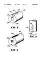
- FIG. 7is a perspective view of a the bottom section of an implant in accordance with the invention showing a recess and a round cavity therein.
- FIG. 8is a perspective view of another embodiment of the bottom section of an implant in accordance with the invention showing a plurality of recesses and a non-round cavity therein.
- FIG. 9is an side view of a further embodiment of the bottom section of an implant in accordance with the invention showing a recess having a cutting surface.
- FIG. 10is a perspective view of an implant employing rings for distributing force.
- FIG. 11is an exploded side view of a fastener in accordance with the invention.
- One preferred embodiment of the present inventionprovides a method for designing a skeletal implant that is adapted for implantation in a patient's bone at a predetermined site.
- predetermined siteincludes any of the possible sites in the body where a skeletal implant may be used (e.g., dental implants, etc.).
- the designerdetermines the patient's bone at the predetermined site with respect to the parameters of width, height, and elastic modulus; generating a macro-design, or large scale design, for the implant based on the measured width and height of the bone at the predetermined site and a desired biomechanical response for the implant.
- a micro-designis then determined for the implant based on the measured elastic modulus of the bone at the predetermined site whereby the implant produces a strain in the bone during functional loading of the implant that is within a predetermined range which promotes bone growth and minimizes bone resorption.
- the micro-designinvolves modifying those parameters that affect the response of the surrounding bone tissue to the implant at the cellular level.
- the designerdetermines the micro-design for the implant based on the measured elastic modulus, using strain equations to ensure that strain in the bone is kept in a range to promote bone growth and to minimize bone resorption during functional loading. This is done by identifying the forces that will be imparted by the implant to the bone at the predetermined implant site and the strain that will be experienced by the bone resulting from the forces imparted by the implant. From this information, the implant designer creates strain equations. The strain equations are applied to the implant design using the characterization parameters of the bone as input to modify the general mechanical macro-design so that the amount of strain in the implanted bone will remain within the desired range, the desired range being between about 100 and 3000 microstrain.
- strain equationsmay be applied using a computer employing any suitable numerical analysis program for optimizing complex equations of the type found in the strain equations, so that the bone contacting surface area induces strain in the desired range. While such programs are generally known to those skilled in the art, one such program is the "OPTDES" interactive computer program from Brigham Young University.
- the different types of bone commonly found in the mandible and maxillamay be assigned to groups, each group having defined average characteristics of width, height, density, and modulus of elasticity.
- the implant designeris thus able to design an implant specific for each one of the groups, the implant being optimized to produce the amount of strain that will enhance new bone growth and osteointegration and minimize resorption in a bone having the average characteristics for the group for which the implant is being designed.
- the dental surgeon employing such an implantis thereby able to characterize a patient's bone, identify the assigned group and select the implant design that corresponds to the group into which the patient's bone characterization belongs.
- Constraint valuesbased upon anatomical dimensional limitations (e.g. buccal-lingual width and crestal height) and mechanical structure of the bone, are identified. These constraints are used to define constraint equations that relate the constraints to the physical forces imparted by the implant. After the constraint equations have been defined for specific regions of the mandible and maxilla, optimization routines are used to refine the macro-design in order to create micro-design features that are specific for each type of implant. The design may be validated by any method obvious to one skilled in the art of implant design. One such method is to perform finite element analyses (FEA) on the resulting designs, thereby validating the performance of each type of dental implant under physiologic functional loading. The FEA is performed on a computer using a program (e.g. "NASTRAN”) that would be obvious to one skilled in the art.
- FEAfinite element analyses
- a preferred embodiment of the apparatus of the present inventiondesigned for use as a dental implant 10, comprises a crest portion 20 attached to a base portion 30.
- the crest portion 20provides a top surface 22 to which a prosthetic device (not shown) may be affixed.
- the crest portion 20also has a bottom surface 24 which is attached to the base portion 30.
- the base portion 30provides a means to affix the implant to the patients mandible or maxilla.
- the base portion 30comprises a substantially conical core section 32 and a thread 40 affixed to the core section 32.
- the core section 32has a crestal end 34 affixed to the bottom surface 24 of the crest portion 20 and an opposite apical end 36.
- the thread 40is continuous and has a first end 46 and a second end 48 which forms a helix around the core section 32 from the apical end 36 to the crestal end 34.
- the thread 40has a thread face 50 which is divided into an upper face 52 and a lower face 54 which are divided by the outermost end 56.
- the thread 40extends radially outward from the outer surface 38 of the core section 32 and terminates at the outermost end 56 of the thread face 50.
- the thread face 50also has an upper face ledge 42 and a lower face ledge 44.
- the apical end 36has a diameter that is smaller than the outside diameter of the thread 40 in order to allow the implant to have the self-tapping feature.
- the angle between the upper face edge 52 and the lower face edge 54approaches 180 degrees as the thread 40 nears the crestal end 34, thereby increasing the surface area in the normal plane to the occlusal forces applied to the implant 10. This is necessary in light of the fact that the greatest amount of force applied to the implant 10 is orthogonal to the occlusal plane. Therefore, normal stresses are of greatest concern, especially in the crestal regions.
- the bottom surface 100 of the base portion 30is flat in order to avoid opposing anatomical landmarks (e.g., the mandibular nerve canal as shown in FIG. 2, item 64) and to provide increased surface area in the normal plane to the applied force.
- the implant 10typically imparts most of the force that occurs as a result of functional loading in the crestal region of the bone. This induces the most strain in the crestal region, which frequently exceeds the physiologic strain levels resulting in bone resorption. Thus, it is desirable to distribute the force imparted on the crestal region of the bone by the implant 10 over a broader surface area, thereby inducing less strain in the crestal region of the implanted bone.
- the total bone contacting surfaceincreases as the thread 40 nears the crestal end 34.
- the bone contacting surface area of the threadcomprises the surfaces of the upper thread ledge 42, the lower thread ledge 44, the upper face edge 52 and the lower face edge 54.
- the radial length of the thread 40 from the outer surface 38 of the core section 32 to the outermost end 56 of the thread face 50increases as the thread 40 nears the crestal end 34. This is a result of both an increase in the angle between the upper thread face 52 and the lower thread face 54 as the thread nears the second end 48, and a narrowing of the core section 32 as it nears the crestal end 34.
- the apical end 36tends to induce less strain in the surrounding bone. If the implant 10 induces less than 100 microstrain the region of the bone near the apical end 36, new bone growth and osteointegration will occur at less than the optimal rate. Therefore, as the thread 40 nears the apical end 36, the radial length of the thread 40 from the outer surface 38 of the core section 32 to the outermost end 56 of the thread face 50 decreases. This is a result of a widening of the core section 32 near the apical end 36 and a decrease of the angle between the upper thread face edge 52 and the lower thread face edge 54. As the thread 40 nears the apical end 36, more strain is induced in the bone surrounding the apical end 36 of the implant 10. The implant 10 of the present invention thus induces strain of at least 100 microstrain in the surrounding bone, thereby promoting new bone growth and osteointegration.
- the level of strain induced in the boneis a function of the stress imparted on the bone by the implant 10.
- the stress profileIn order to maintain a uniform strain profile along the entire length of the implant 10, the stress profile must be uniform.
- Clinical experiencehas demonstrated crestal resorption surrounding root form dental implants. As has been shown in analytical studies, stresses are markedly increased in bone near the crestal regions of dental implants. This stress may be reduced in the crestal region by increasing the surface area in contact with the bone at the crestal region. In the preferred embodiment of the present invention, this area is progressively increased as the thread 40 approaches the top of the implant by using a gradually increasing thread depth.
- the preselected anglewherein the angle is a function of the vertical position of the thread along the length of the implant, between the upper face edge 52 and lower face edge 54 approach 180 degrees at a preselected rate, the rate being determined by the strain equations, as it advances to the top of the implant.
- the outside diameter of the implantmust remain constant.
- the hole drilled into the bone for placement of the implantmay have a constant inside diameter.
- a constant outside diameterwill allow the implant to have self-tapping threads which can engage the cortical plate for increased stability. This feature establishes the need for a tapered implant core.
- the tapered coreenables the thread surface area to increase gradually toward the crestal region of the implant while the outside diameter remains constant.
- the following classification of trabecular bone densityare used to provide constraints for the design: D1, D2 (coarse), D3 & D4 (fine).
- the moduli of elasticity for the trabecular bonehas been quantified for these densities.
- the modulus for D2is 67.5 MPa and the modulus for D3 and D4 is 35.5 MPa.
- the various bone shapes of the mandiblecan be characterized into six divisions. Of these divisions, divisions A 60 and B 70 and are immediate candidates in the posterior mandible for using an implant in accordance with this preferred embodiment of the present invention. Divisions C-h 76, B-W 72, C-W 74, and D 78 would be candidates for this embodiment following bone grafting procedures.
- the available height, width and length of available bonemust also be assessed for each patient. The height is measured from the crest 62 of the endentulous ridge to the opposing landmark (e.g. the maxillary sinus or mandibular canal 64).
- the widthis measured from the facial plate 66 to the lingual plate 68 at the crest. The length is limited by adjacent teeth or other implants (not shown). The outside diameter of the implant depends on the width and length of the available bone.
- the crest portion 20is incorporated into the implant design in order to provide a point of attachment for a prosthesis (not shown) and to provide a crestal bone seal.
- the diameter of the crest portionvaries according to bone type, ranging from approximately 0.4 mm larger than the outside diameter of the implant with D4-type bone to a diameter that is equal to the outside diameter in D1-type bone.
- the larger diameter in D4 boneaids in the dissipation of forces in that crestal region below the crest portion 20.
- the crest portion 20also compensates for increased bone loss that may occur during the surgical process and ensures an adequate crestal bone seal.
- bite forcesin the range of 42 to 2500 Newtons, therefore these limits are used for the force constraint used to optimize the design.
- nthe number of turns of the thread around the core section.
- DTthe diameter of the base portion from thread to thread.
- BDthe diameter of the apical end.
- TDthe diameter of the crestal end.
- Hthe height of the base portion.
- Thone-half of the width of the thread.
- Ethe modulus of elasticity for D2 or D3 or D4 trabecular bone densities.
- ⁇the shear strain induced in the bone.
- ⁇the normal strain induced in the bone.
- ⁇the angle of the thread face edges to normal.
- ⁇the angle of the outer surface of the core section to normal.
- strain equationscontain each of the geometric variables used to describe the macro-design. These strain equations are employed in a computer optimization program in order to optimize the design. Once optimized in accordance with the above strain equations, the design will induce strain in the desired range in the implanted bone.
- a dental implant 105may comprise a groove 120, transverse to the thread 110, to prevent rotation of the implant 105.
- a threaded first section 230has a crestal end 234 and an apical end 236.
- the crestal end 234abuts the bottom end 224 of the crest module 220.
- the threaded first section 230defines a helical thread 250 extending from near the apical end 236 to near the crestal end 234.
- a substantially cylindrical second section 260extends longitudinally from the apical end 236 of the first section 230 and terminates in an end surface 262.
- the second section 260defines at least one recess 270 along a portion of its length for receiving bone therein.
- the embodiment shown in FIG. 6employs four such recesses 270.
- many configurations of recesses 270could be employed without departing from the scope of the invention.
- One such configurationcould include many small, or even semi-microscopic recesses. Non-longitudinal recesses, such as spiral recesses, are possible.
- the recess 270has a first end 272 and an opposite second end 274.
- An interior surface 276extends from the first end 272 to the second end 274, with the interior surface 276 being tapered inwardly from the first end 272 to the second end 274 so that a longitudinally directed force imparted on the implant 210 is distributed to the bone in a direction normal to the interior surface 276.
- the end surface 262 of the second section 260defines a centrally located cavity 264 that relieves fluid pressure in the implanted bone.
- an inwardly tapered, longitudinally extending recessare possible on the second section 360.
- Theseinclude a curved recess 370a and a V-shaped recess 370b.
- a non-circular cavity 364can be employed to relieve fluid pressure from the bone near the end surface 362.
- the crest module 220defines a longitudinally extending abutment screw bore 290.
- the surface of the borehas an interior threaded portion 292 defining a helical locking thread with an interior non-threaded portion 294 extending coaxially therefrom.
- An abutment screw 280 adapted for insertion into the abutment screw bore 290has an exterior threaded portion 282, that is complimentary in shape to the interior threaded portion 292, and an exterior non-threaded portion 284 extending longitudinally therefrom.
- the interior non-threaded portion 294is complimentary in shape to the exterior non-threaded portion 284 so that the interior non-threaded portion 294 is capable of receiving therein the exterior non-threaded portion 284 so as to aid in the alignment of the exterior threaded portion 284 of the abutment screw 280 with the interior threaded portion 292 of the abutment screw bore 290.
- the implant recess 470may be provided with a means for removing bone from the inner surface of the hole as the implant is being implanted, so as to aid in conforming the shape of the hole to the shape of the implant.
- the bone removal meanscould comprise a first cutting surface 478 formed on the end of the recess 470 which extends through end surface 462 or a second cutting surface 479 formed on a longitudinal edge of the recess 470 adjacent the exterior surface of the second section 460, or both the first cutting surface 478 and the second cutting surface 479 may be employed.
- the cutting surfaces 478 and 479are configured to remove bone as the implant rotates in the direction of arrow A.
- the implantcomprises a circular crest module 420 having a top surface 430 and an opposite bottom end 422, a sidewall 434 interconnecting the top surface 430 and the bottom end 422.
- the crest module 420defines a bore 432 extending axially into the crest module 420 from the top surface 430.
- a section 460extends longitudinally from the bottom end 422, tapering inwardly away from the bottom end 422, and a plurality of spaced apart rings 476 radially disposed along the length of section 460 so as to distribute a portion of any force imparted on the implant to the bone.
- Each ringhas an outer surface 480 that, in one embodiment, is coextensive with side wall 434.
- an alternative embodiment of the inventionis a fastener 510 comprising an elongated male member 580 having an end portion 586, an external threaded portion 582 adjacent the end portion 586 and an external non-threaded portion 584 extending therefrom, the diameter of portion 582 being greater than the diameter of portion 584.
- a female member 520has a first end 522 and defines an elongated bore 590 longitudinally extending from the first end 522.
- the bore 590has an interior threaded portion 592 adjacent the first end 522 and an interior non-threaded portion 594 extending longitudinally from the interior threaded portion 592.
- the interior non-threaded portion 594can receive therein the exterior non-threaded portion 584 so as to aid in the alignment of the exterior threaded portion 582 of the male member 580 with the interior threaded portion 592 of the female member 520.
- a device for applying stimulation to the implantsuch as the Sonic Accelerated Fracture Healing System (SAFHS®) developed by Exogen, Inc. uses low-intensity, pulsed ultrasound to accelerate fresh fracture healing.
- the devicemay be prescribed by a physician and self-administered by the patient for daily 20 minute treatments.
Landscapes
- Health & Medical Sciences (AREA)
- Oral & Maxillofacial Surgery (AREA)
- Orthopedic Medicine & Surgery (AREA)
- Dentistry (AREA)
- Epidemiology (AREA)
- Life Sciences & Earth Sciences (AREA)
- Animal Behavior & Ethology (AREA)
- General Health & Medical Sciences (AREA)
- Public Health (AREA)
- Veterinary Medicine (AREA)
- Dental Prosthetics (AREA)
Abstract
Description
σ=Eε
τ=Gγ
______________________________________ Trabecular Bone Implant properties Outer Implant E = elastic Diameter, Height, modulus Axial MechanicalDensity OD (mm) h (mm) (MPa) Force (Newtons)______________________________________Division A: 3.8<OD≦4.5 12<h≦16 N/A 42-2500D1 4.5<OD≦5.5D2a 3.8<OD≦4.5 12<h≦16 67.5 42-2500 4.5<OD≦5.5D2b 3.8<OD≦4.5 12<h≦16 67.5 42-2500 4.5<OD≦5.5D3a 3.8<OD≦4.5 12<h≦16 35.5 42-2500 4.5<OD≦5.5D3b 3.8<OD≦4.5 12<h≦6 35.5 42-2500 4.5<OD≦5.5D4 3.8<OD≦4.5 12<h≦16 35.5 42-2500 4.5<OD≦5.5Division B: 3.0<OD≦3.8 10<h≦16 N/A 42-2500D1D2a 3.0<OD≦3.8 10<h≦16 67.5 42-2500D2b 3.0<OD≦3.8 10<h≦16 67.5 42-2500D3a 3.0<OD≦3 8 10<h≦16 35.5 42-2500D3b 3.0<OD≦3.8 10<h≦16 35.5 42-2500D4 3.0<OD≦3.8 10<h≦16 35.5 42-2500Division C-h: 3.8<OD≦4.5 10<h≦14 N/A 42-2500D1 4.5<OD≦5.5D2a 3.8<OD≦4.5 10<h≦14 67.5 42-2500 4.5<OD≦5.5D2b 3.8<OD≦4.5 10<h≦14 67.5 42-2500 4.5<OD≦5.5D3a 3.8<OD≦4.5 10<h≦14 35.5 42-2500 4.5<OD≦5.5D3b 3.8<OD≦4.5 10<h≦14 35.5 42-2500 4.5<OD≦5.5D4 3.8<OD≦4.5 10<h≦14 35.5 42-2500 4.5<OD≦5.5______________________________________
Claims (13)
Priority Applications (1)
| Application Number | Priority Date | Filing Date | Title |
|---|---|---|---|
| US08/828,673US5954504A (en) | 1997-03-31 | 1997-03-31 | Design process for skeletal implants to optimize cellular response |
Applications Claiming Priority (1)
| Application Number | Priority Date | Filing Date | Title |
|---|---|---|---|
| US08/828,673US5954504A (en) | 1997-03-31 | 1997-03-31 | Design process for skeletal implants to optimize cellular response |
Publications (1)
| Publication Number | Publication Date |
|---|---|
| US5954504Atrue US5954504A (en) | 1999-09-21 |
Family
ID=25252440
Family Applications (1)
| Application Number | Title | Priority Date | Filing Date |
|---|---|---|---|
| US08/828,673Expired - LifetimeUS5954504A (en) | 1997-03-31 | 1997-03-31 | Design process for skeletal implants to optimize cellular response |
Country Status (1)
| Country | Link |
|---|---|
| US (1) | US5954504A (en) |
Cited By (33)
| Publication number | Priority date | Publication date | Assignee | Title |
|---|---|---|---|---|
| USD427684S (en)* | 1998-08-05 | 2000-07-04 | Astra Aktiebolag | Implant |
| USD427683S (en)* | 1998-07-10 | 2000-07-04 | Sulzer Calcitek Inc. | Dental abutment |
| US20040146834A1 (en)* | 2001-02-02 | 2004-07-29 | Dieter Haessler | Implant system |
| US20070281280A1 (en)* | 2006-05-30 | 2007-12-06 | Ormco Corporation | Method and system for single tooth replacement in a growing individual |
| US7338286B2 (en) | 2002-11-13 | 2008-03-04 | Biomet 3I, Inc. | Dental implant system |
| US20080064010A1 (en)* | 2003-06-30 | 2008-03-13 | Ten Bruggenkate Christiaan Mic | Intra-Osseous Implant |
| US20100234903A1 (en)* | 2003-04-30 | 2010-09-16 | Biedermann Motech Gmbh | Bone anchoring element with thread that can be unscrewed |
| US20100261142A1 (en)* | 2009-04-08 | 2010-10-14 | Peter Metz-Stavenhagen | Dental implant |
| US20130065198A1 (en)* | 2011-09-14 | 2013-03-14 | Marcus Abboud | Jaw implant |
| US20140121776A1 (en)* | 2012-09-25 | 2014-05-01 | 4Web, Inc. | Programmable implants and methods of using programmable implants to repair bone structures |
| US9386962B2 (en)* | 2008-04-21 | 2016-07-12 | University Of Washington | Method and apparatus for evaluating osteointegration of medical implants |
| US9421108B2 (en) | 2008-12-18 | 2016-08-23 | 4Web, Inc. | Implant system and method |
| US9636226B2 (en) | 2013-03-15 | 2017-05-02 | 4Web, Inc. | Traumatic bone fracture repair systems and methods |
| US9681930B2 (en) | 2014-12-15 | 2017-06-20 | Jjgc Industria E Comercio De Materiais Dentarious S/A | Implants for enhanced anchoring within bone |
| US9861455B2 (en) | 2013-07-30 | 2018-01-09 | TI Intellectual Property Inc. | Dental implant system |
| US9925024B2 (en) | 2011-06-28 | 2018-03-27 | Biomet 3I, Llc | Dental implant and abutment tools |
| ES2663539A1 (en)* | 2017-12-05 | 2018-04-13 | Julián CUESTA GARCIA | Highly self-tapping dental implant system with hybrid connection and parallel double cone block between the prosthetic abutment, the implant and the internal screw. (Machine-translation by Google Translate, not legally binding) |
| USD816841S1 (en) | 2014-12-15 | 2018-05-01 | Jjgc Industria E Comercio De Materiais Dentarios S/A | Bone implant |
| US10898301B2 (en) | 2016-05-05 | 2021-01-26 | Jjgc Industria E Comercio De Materiais Dentarios S.A. | Prosthetic assembly and method for producing the same |
| US11786343B2 (en) | 2020-07-09 | 2023-10-17 | Southern Implants (Pty) Ltd | Dental implants with stepped threads and systems and methods for making the same |
| US11793652B2 (en) | 2017-11-21 | 2023-10-24 | Institute for Musculoskeletal Science and Education, Ltd. | Implant with improved bone contact |
| US11819419B2 (en) | 2015-04-29 | 2023-11-21 | Institute for Musculoskeletal Science and Education, Ltd. | Implant with curved bone contacting elements |
| US11826261B2 (en) | 2015-04-29 | 2023-11-28 | Institute for Musculoskeletal Science and Education, Ltd. | Coiled implants and systems and methods of use thereof |
| US11938039B2 (en) | 2017-03-13 | 2024-03-26 | Institute for Musculoskeletal Science and Education, Ltd. | Implant with structural members arranged around a ring |
| US11951018B2 (en) | 2017-11-21 | 2024-04-09 | Institute for Musculoskeletal Science and Education, Ltd. | Implant with improved flow characteristics |
| US20240122629A1 (en)* | 2008-06-06 | 2024-04-18 | Providence Medical Technology, Inc. | Vertebral joint implants and delivery tools |
| US12042399B2 (en) | 2016-10-25 | 2024-07-23 | Institute for Musculoskeletal Science and Education, Ltd. | Implant with protected fusion zones |
| US12097123B2 (en) | 2015-04-29 | 2024-09-24 | Institute for Musculoskeletal Science and Education, Ltd. | Implant with arched bone contacting elements |
| US12102535B2 (en) | 2019-11-15 | 2024-10-01 | 4Web, Llc | Piezoelectric coated implants and methods of using piezoelectric coated implants to repair bone structures |
| US12115071B2 (en) | 2012-09-25 | 2024-10-15 | 4Web, Llc | Programmable intramedullary implants and methods of using programmable intramedullary implants to repair bone structures |
| US12201531B2 (en) | 2020-07-08 | 2025-01-21 | 4Web, Llc | Implants having bone growth promoting agents contained within biodegradable materials |
| US12208011B2 (en) | 2016-10-25 | 2025-01-28 | Institute for Musculoskeletal Science and Education, Ltd. | Implant with multi-layer bone interfacing lattice |
| US12279964B2 (en) | 2008-12-18 | 2025-04-22 | 4Web, Llc | Implants having bone growth promoting agents and methods of using such implants to repair bone structures |
Citations (53)
| Publication number | Priority date | Publication date | Assignee | Title |
|---|---|---|---|---|
| US35784A (en)* | 1862-07-01 | Improvement in harrows | ||
| US3708883A (en)* | 1971-01-04 | 1973-01-09 | S Flander | Dental implant and method for using the same |
| US4086701A (en)* | 1975-04-07 | 1978-05-02 | Kyoto Ceramic Kabushiki Kaisha | Device for implanting an artificial endosseous element of ceramics and an implant method for use of the same |
| US4103422A (en)* | 1975-03-07 | 1978-08-01 | Oratronics, Inc. | Threaded self-tapping endodontic stabilizer |
| US4185383A (en)* | 1976-05-04 | 1980-01-29 | Friedrichsfeld Gmbh. Steinzeug-Und Kunststoffwerke | Dental implant having a biocompatible surface |
| US4229169A (en)* | 1977-11-17 | 1980-10-21 | Smith Peter J | Dental prostheses fitting |
| US4231120A (en)* | 1977-09-22 | 1980-11-04 | National Research Development Corporation | Endoprosthetic orthopaedic devices |
| US4293302A (en)* | 1980-03-26 | 1981-10-06 | Scientific Advances, Inc. | Tooth implants |
| US4304553A (en)* | 1975-11-03 | 1981-12-08 | Friedrichsfeld Gmbh | Dental implant formed of AL2 O3 -ceramic for fastening a superstructure |
| US4324550A (en)* | 1979-11-21 | 1982-04-13 | Osteo Ag | Implant for the jaw |
| US4406623A (en)* | 1981-01-09 | 1983-09-27 | Grafelmann Hans L | Screw-type bone implant for receiving a dental prosthesis |
| US4408990A (en)* | 1982-04-26 | 1983-10-11 | Misch Carl E | Endodontic dental implant |
| US4424037A (en)* | 1981-02-04 | 1984-01-03 | Nippon Kogaku K.K. | Dental implant |
| US4466796A (en)* | 1980-10-20 | 1984-08-21 | Cbs Biotechnic Sa | Dental implant for use as a pillar in a mouth |
| US4486178A (en)* | 1982-08-14 | 1984-12-04 | Friedrichsfeld Gmbh Steinzeug-Und Kunststoffwerke | Tooth implant made of metal |
| US4531915A (en)* | 1981-08-14 | 1985-07-30 | Tatum Jr O Hilt | Dental implant |
| US4560353A (en)* | 1982-07-17 | 1985-12-24 | Friedrichsfeld Gmbh - Steinzeug- Und Kunststoffwerke | Tooth implant |
| US4609354A (en)* | 1984-04-11 | 1986-09-02 | Implanto-Lock Gmbh | Enossal implant for securing a tight-fitting tooth replacement |
| US4613308A (en)* | 1984-06-06 | 1986-09-23 | Feldmuhle Aktiengesellschaft | Jaw implant having an aperture to receive a replacement-tooth holder |
| US4622010A (en)* | 1983-09-03 | 1986-11-11 | Implanto-Lock Gmbh | Enossal implant for securing a tight-fitting tooth replacement |
| US4626214A (en)* | 1983-05-17 | 1986-12-02 | Artal Alberto A | Fixed dental implant |
| US4671768A (en)* | 1982-12-06 | 1987-06-09 | Ton Michael A | Implant as well as a dental prosthesis attached to one or more of such implants |
| US4744754A (en)* | 1986-08-13 | 1988-05-17 | Ross Systems Corporation | Dental implant and method for installing same into bone tissue |
| US4744755A (en)* | 1986-08-13 | 1988-05-17 | Ross Systems Corporation | Dental implant and method for installing same |
| US4746294A (en)* | 1986-03-27 | 1988-05-24 | Domenico Colombo | Cylindrical threaded pin for dental prosthesis implantations |
| US4790753A (en)* | 1987-02-13 | 1988-12-13 | Fradera Alejandro P | Screw for dental implants |
| US4826434A (en)* | 1986-10-20 | 1989-05-02 | Steri-Oss, Inc. | Dental implant |
| US4976739A (en)* | 1986-05-15 | 1990-12-11 | Duthie Jr Robert E | Implant system |
| US4988299A (en)* | 1988-05-20 | 1991-01-29 | The Institute For Applied Biotechnology | Implant fixture for tooth prosthesis |
| US5000686A (en)* | 1990-01-02 | 1991-03-19 | Implant Innovations, Inc. | Dental implant fixture |
| US5064425A (en)* | 1986-02-12 | 1991-11-12 | The Institute For Applied Biotechnology | Anchoring member for anchorage in bone tissue |
| US5082445A (en)* | 1988-08-12 | 1992-01-21 | Shmuel Singer | Osteointegrated implants and dental implant assemblies |
| US5088926A (en)* | 1990-01-05 | 1992-02-18 | Manfred Lang | Implant for the jawbone |
| US5092771A (en)* | 1990-11-21 | 1992-03-03 | Tatum Iii O Hilt | Rotary dental implant post |
| US5122059A (en)* | 1990-09-08 | 1992-06-16 | Eberle Medizintechnische Element Gmbh | Enossal implant for a firmly seated tooth replacement |
| US5259398A (en)* | 1989-10-26 | 1993-11-09 | Giuseppe Vrespa | Method for fixing prosthesis to bones |
| US5312255A (en)* | 1989-06-05 | 1994-05-17 | Ernst Bauer | Screw implant for a jawbone |
| US5338197A (en)* | 1993-04-13 | 1994-08-16 | Kwan Norman H K | Dental implant having cutting means |
| US5427527A (en)* | 1993-05-25 | 1995-06-27 | Vent Plant Corporation | Dental implant method of installation |
| US5435723A (en)* | 1993-08-18 | 1995-07-25 | O'brien; Gary R. | Endosseous dental implant system |
| US5527183A (en)* | 1993-08-18 | 1996-06-18 | Collaborative Enterprises, Inc. | Endosseous implant system |
| US5533898A (en)* | 1993-11-18 | 1996-07-09 | Mena; Raul | Dental implant device |
| US5588838A (en)* | 1992-10-28 | 1996-12-31 | Astra Aktiebolag | Fixture for use in a dental implant system |
| US5601429A (en)* | 1995-08-11 | 1997-02-11 | Blacklock; Gordon D. | Dental implant anchor |
| US5620323A (en)* | 1994-08-22 | 1997-04-15 | Bressman; Robert A. | Dental restoration structure |
| US5681167A (en)* | 1996-01-05 | 1997-10-28 | Lazarof; Sargon | Dental assembly and process for preparing a tooth prosthesis |
| US5695336A (en)* | 1992-03-03 | 1997-12-09 | Implant Innovations, Inc. | Dental implant fixture for anchorage in cortical bone |
| US5725377A (en)* | 1996-03-29 | 1998-03-10 | Lemler; Jeffrey Richard | Dental implant apparatus |
| US5727943A (en)* | 1995-07-18 | 1998-03-17 | Implant Innovations, Inc. | Self-tapping, screw-type dental implant |
| USRE35784E (en) | 1986-09-04 | 1998-05-05 | Vent-Plant Corporation | Submergible screw-type dental implant and method of utilization |
| US5749732A (en)* | 1995-10-03 | 1998-05-12 | Sendax; Victor | Dental implantation |
| US5752830A (en)* | 1996-06-20 | 1998-05-19 | Suarez; Omar F. | Removable dental implant |
| US5772437A (en)* | 1993-12-20 | 1998-06-30 | Nobel Biocare Ab | Securing element |
- 1997
- 1997-03-31USUS08/828,673patent/US5954504A/ennot_activeExpired - Lifetime
Patent Citations (53)
| Publication number | Priority date | Publication date | Assignee | Title |
|---|---|---|---|---|
| US35784A (en)* | 1862-07-01 | Improvement in harrows | ||
| US3708883A (en)* | 1971-01-04 | 1973-01-09 | S Flander | Dental implant and method for using the same |
| US4103422A (en)* | 1975-03-07 | 1978-08-01 | Oratronics, Inc. | Threaded self-tapping endodontic stabilizer |
| US4086701A (en)* | 1975-04-07 | 1978-05-02 | Kyoto Ceramic Kabushiki Kaisha | Device for implanting an artificial endosseous element of ceramics and an implant method for use of the same |
| US4304553A (en)* | 1975-11-03 | 1981-12-08 | Friedrichsfeld Gmbh | Dental implant formed of AL2 O3 -ceramic for fastening a superstructure |
| US4185383A (en)* | 1976-05-04 | 1980-01-29 | Friedrichsfeld Gmbh. Steinzeug-Und Kunststoffwerke | Dental implant having a biocompatible surface |
| US4231120A (en)* | 1977-09-22 | 1980-11-04 | National Research Development Corporation | Endoprosthetic orthopaedic devices |
| US4229169A (en)* | 1977-11-17 | 1980-10-21 | Smith Peter J | Dental prostheses fitting |
| US4324550A (en)* | 1979-11-21 | 1982-04-13 | Osteo Ag | Implant for the jaw |
| US4293302A (en)* | 1980-03-26 | 1981-10-06 | Scientific Advances, Inc. | Tooth implants |
| US4466796A (en)* | 1980-10-20 | 1984-08-21 | Cbs Biotechnic Sa | Dental implant for use as a pillar in a mouth |
| US4406623A (en)* | 1981-01-09 | 1983-09-27 | Grafelmann Hans L | Screw-type bone implant for receiving a dental prosthesis |
| US4424037A (en)* | 1981-02-04 | 1984-01-03 | Nippon Kogaku K.K. | Dental implant |
| US4531915A (en)* | 1981-08-14 | 1985-07-30 | Tatum Jr O Hilt | Dental implant |
| US4408990A (en)* | 1982-04-26 | 1983-10-11 | Misch Carl E | Endodontic dental implant |
| US4560353A (en)* | 1982-07-17 | 1985-12-24 | Friedrichsfeld Gmbh - Steinzeug- Und Kunststoffwerke | Tooth implant |
| US4486178A (en)* | 1982-08-14 | 1984-12-04 | Friedrichsfeld Gmbh Steinzeug-Und Kunststoffwerke | Tooth implant made of metal |
| US4671768A (en)* | 1982-12-06 | 1987-06-09 | Ton Michael A | Implant as well as a dental prosthesis attached to one or more of such implants |
| US4626214A (en)* | 1983-05-17 | 1986-12-02 | Artal Alberto A | Fixed dental implant |
| US4622010A (en)* | 1983-09-03 | 1986-11-11 | Implanto-Lock Gmbh | Enossal implant for securing a tight-fitting tooth replacement |
| US4609354A (en)* | 1984-04-11 | 1986-09-02 | Implanto-Lock Gmbh | Enossal implant for securing a tight-fitting tooth replacement |
| US4613308A (en)* | 1984-06-06 | 1986-09-23 | Feldmuhle Aktiengesellschaft | Jaw implant having an aperture to receive a replacement-tooth holder |
| US5064425A (en)* | 1986-02-12 | 1991-11-12 | The Institute For Applied Biotechnology | Anchoring member for anchorage in bone tissue |
| US4746294A (en)* | 1986-03-27 | 1988-05-24 | Domenico Colombo | Cylindrical threaded pin for dental prosthesis implantations |
| US4976739A (en)* | 1986-05-15 | 1990-12-11 | Duthie Jr Robert E | Implant system |
| US4744754A (en)* | 1986-08-13 | 1988-05-17 | Ross Systems Corporation | Dental implant and method for installing same into bone tissue |
| US4744755A (en)* | 1986-08-13 | 1988-05-17 | Ross Systems Corporation | Dental implant and method for installing same |
| USRE35784E (en) | 1986-09-04 | 1998-05-05 | Vent-Plant Corporation | Submergible screw-type dental implant and method of utilization |
| US4826434A (en)* | 1986-10-20 | 1989-05-02 | Steri-Oss, Inc. | Dental implant |
| US4790753A (en)* | 1987-02-13 | 1988-12-13 | Fradera Alejandro P | Screw for dental implants |
| US4988299A (en)* | 1988-05-20 | 1991-01-29 | The Institute For Applied Biotechnology | Implant fixture for tooth prosthesis |
| US5082445A (en)* | 1988-08-12 | 1992-01-21 | Shmuel Singer | Osteointegrated implants and dental implant assemblies |
| US5312255A (en)* | 1989-06-05 | 1994-05-17 | Ernst Bauer | Screw implant for a jawbone |
| US5259398A (en)* | 1989-10-26 | 1993-11-09 | Giuseppe Vrespa | Method for fixing prosthesis to bones |
| US5000686A (en)* | 1990-01-02 | 1991-03-19 | Implant Innovations, Inc. | Dental implant fixture |
| US5088926A (en)* | 1990-01-05 | 1992-02-18 | Manfred Lang | Implant for the jawbone |
| US5122059A (en)* | 1990-09-08 | 1992-06-16 | Eberle Medizintechnische Element Gmbh | Enossal implant for a firmly seated tooth replacement |
| US5092771A (en)* | 1990-11-21 | 1992-03-03 | Tatum Iii O Hilt | Rotary dental implant post |
| US5695336A (en)* | 1992-03-03 | 1997-12-09 | Implant Innovations, Inc. | Dental implant fixture for anchorage in cortical bone |
| US5588838A (en)* | 1992-10-28 | 1996-12-31 | Astra Aktiebolag | Fixture for use in a dental implant system |
| US5338197A (en)* | 1993-04-13 | 1994-08-16 | Kwan Norman H K | Dental implant having cutting means |
| US5427527A (en)* | 1993-05-25 | 1995-06-27 | Vent Plant Corporation | Dental implant method of installation |
| US5435723A (en)* | 1993-08-18 | 1995-07-25 | O'brien; Gary R. | Endosseous dental implant system |
| US5527183A (en)* | 1993-08-18 | 1996-06-18 | Collaborative Enterprises, Inc. | Endosseous implant system |
| US5533898A (en)* | 1993-11-18 | 1996-07-09 | Mena; Raul | Dental implant device |
| US5772437A (en)* | 1993-12-20 | 1998-06-30 | Nobel Biocare Ab | Securing element |
| US5620323A (en)* | 1994-08-22 | 1997-04-15 | Bressman; Robert A. | Dental restoration structure |
| US5727943A (en)* | 1995-07-18 | 1998-03-17 | Implant Innovations, Inc. | Self-tapping, screw-type dental implant |
| US5601429A (en)* | 1995-08-11 | 1997-02-11 | Blacklock; Gordon D. | Dental implant anchor |
| US5749732A (en)* | 1995-10-03 | 1998-05-12 | Sendax; Victor | Dental implantation |
| US5681167A (en)* | 1996-01-05 | 1997-10-28 | Lazarof; Sargon | Dental assembly and process for preparing a tooth prosthesis |
| US5725377A (en)* | 1996-03-29 | 1998-03-10 | Lemler; Jeffrey Richard | Dental implant apparatus |
| US5752830A (en)* | 1996-06-20 | 1998-05-19 | Suarez; Omar F. | Removable dental implant |
Cited By (72)
| Publication number | Priority date | Publication date | Assignee | Title |
|---|---|---|---|---|
| USD427683S (en)* | 1998-07-10 | 2000-07-04 | Sulzer Calcitek Inc. | Dental abutment |
| USD427684S (en)* | 1998-08-05 | 2000-07-04 | Astra Aktiebolag | Implant |
| US20040146834A1 (en)* | 2001-02-02 | 2004-07-29 | Dieter Haessler | Implant system |
| DE10204324B4 (en)* | 2001-02-02 | 2007-03-29 | Friadent Gmbh | implant system |
| US7210933B2 (en) | 2001-02-02 | 2007-05-01 | Friadent Gmbh | Implant system |
| US9549793B2 (en) | 2002-11-13 | 2017-01-24 | Biomet 3I, Llc | Dental implant system |
| US8636511B2 (en) | 2002-11-13 | 2014-01-28 | Biomet 3I, Llc | Dental implant system |
| US9931182B2 (en) | 2002-11-13 | 2018-04-03 | Biomet 3I, Llc | Dental implant system |
| US7484959B2 (en) | 2002-11-13 | 2009-02-03 | Biomet 3I, Llc | Dental implant system |
| US7338286B2 (en) | 2002-11-13 | 2008-03-04 | Biomet 3I, Inc. | Dental implant system |
| US9883927B2 (en) | 2002-11-13 | 2018-02-06 | Biomet 3I, Llc | Dental implant system |
| US20100234903A1 (en)* | 2003-04-30 | 2010-09-16 | Biedermann Motech Gmbh | Bone anchoring element with thread that can be unscrewed |
| US10285744B2 (en) | 2003-04-30 | 2019-05-14 | Biedermann Technologies Gmbh & Co. Kg | Bone anchoring element with thread that can be unscrewed |
| US9572639B2 (en)* | 2003-06-30 | 2017-02-21 | Ten Bruggenkate Kaakchirugie B.V. | Intra-osseous implant |
| US20080064010A1 (en)* | 2003-06-30 | 2008-03-13 | Ten Bruggenkate Christiaan Mic | Intra-Osseous Implant |
| US8496478B2 (en)* | 2003-06-30 | 2013-07-30 | Ten Bruggenkate Kaakchirugie B.V. | Intra-osseous implant |
| US7955080B2 (en) | 2006-05-30 | 2011-06-07 | Ormco Corporation | Method and system for single tooth replacement in a growing individual |
| US20070281280A1 (en)* | 2006-05-30 | 2007-12-06 | Ormco Corporation | Method and system for single tooth replacement in a growing individual |
| US9386962B2 (en)* | 2008-04-21 | 2016-07-12 | University Of Washington | Method and apparatus for evaluating osteointegration of medical implants |
| US20240122629A1 (en)* | 2008-06-06 | 2024-04-18 | Providence Medical Technology, Inc. | Vertebral joint implants and delivery tools |
| US12263094B2 (en) | 2008-12-18 | 2025-04-01 | 4Web, Llc | Implant having a shaft coated with a web structure |
| US9421108B2 (en) | 2008-12-18 | 2016-08-23 | 4Web, Inc. | Implant system and method |
| US11510787B2 (en) | 2008-12-18 | 2022-11-29 | 4-Web Spine, Inc. | Implant having a shaft coated with a web structure |
| US9545317B2 (en) | 2008-12-18 | 2017-01-17 | 4Web, Inc. | Implant interface system and device |
| US9999516B2 (en) | 2008-12-18 | 2018-06-19 | 4Web, Inc. | Implant device having a non-planar surface |
| US11278421B2 (en) | 2008-12-18 | 2022-03-22 | 4Web, Inc. | Implant device having curved or arced struts |
| US12279964B2 (en) | 2008-12-18 | 2025-04-22 | 4Web, Llc | Implants having bone growth promoting agents and methods of using such implants to repair bone structures |
| US9713513B2 (en)* | 2009-04-08 | 2017-07-25 | Peter Metz-Stavenhagen | Dental implant |
| US20100261142A1 (en)* | 2009-04-08 | 2010-10-14 | Peter Metz-Stavenhagen | Dental implant |
| US10201405B2 (en) | 2011-06-28 | 2019-02-12 | Biomet 3I, Llc | System and method of dental implant and interface to abutment for restoration |
| US10952826B2 (en) | 2011-06-28 | 2021-03-23 | Biomet 3I, Llc | System and method of dental implant and interface to abutment for restoration |
| US9925024B2 (en) | 2011-06-28 | 2018-03-27 | Biomet 3I, Llc | Dental implant and abutment tools |
| US20130065198A1 (en)* | 2011-09-14 | 2013-03-14 | Marcus Abboud | Jaw implant |
| US9039417B2 (en)* | 2011-09-14 | 2015-05-26 | Marcus Abboud | Jaw implant |
| JP2015529150A (en)* | 2012-09-25 | 2015-10-05 | フォー−ウェブ・インコーポレイテッド | Programmable graft and method of using a programmable graft to repair bone structure |
| US9757235B2 (en)* | 2012-09-25 | 2017-09-12 | 4Web, Inc. | Spinal programmable implant |
| US9572669B2 (en) | 2012-09-25 | 2017-02-21 | 4-Web, Inc. | Programmable implant having an angled exterior surface |
| US20170360563A1 (en)* | 2012-09-25 | 2017-12-21 | 4Web | Programmable implant having curved or arced struts |
| US20140121776A1 (en)* | 2012-09-25 | 2014-05-01 | 4Web, Inc. | Programmable implants and methods of using programmable implants to repair bone structures |
| CN104780870A (en)* | 2012-09-25 | 2015-07-15 | 4网络公司 | Programmable implants and methods of using programmable implants to repair bone structures |
| US9987137B2 (en)* | 2012-09-25 | 2018-06-05 | 4Web, Inc. | Programmable implant having curved or arced struts |
| US10849756B2 (en)* | 2012-09-25 | 2020-12-01 | 4Web Medical | Programmable implant |
| US12115071B2 (en) | 2012-09-25 | 2024-10-15 | 4Web, Llc | Programmable intramedullary implants and methods of using programmable intramedullary implants to repair bone structures |
| US9271845B2 (en)* | 2012-09-25 | 2016-03-01 | 4Web | Programmable implants and methods of using programmable implants to repair bone structures |
| CN104780870B (en)* | 2012-09-25 | 2018-03-02 | 4网络公司 | Programmable implant and the method for repairing bone structure using programmable implant |
| US20160287388A1 (en)* | 2012-09-25 | 2016-10-06 | 4Web, Inc. | Programmable implant having struts with different physical properties |
| US9549823B2 (en) | 2012-09-25 | 2017-01-24 | 4-Web, Inc. | Programmable implant having curved or arced struts |
| US9636226B2 (en) | 2013-03-15 | 2017-05-02 | 4Web, Inc. | Traumatic bone fracture repair systems and methods |
| US9861455B2 (en) | 2013-07-30 | 2018-01-09 | TI Intellectual Property Inc. | Dental implant system |
| US9681930B2 (en) | 2014-12-15 | 2017-06-20 | Jjgc Industria E Comercio De Materiais Dentarious S/A | Implants for enhanced anchoring within bone |
| USD837378S1 (en) | 2014-12-15 | 2019-01-01 | Jjgc Industria E Comercio De Materiais Dentarios S/A | Bone implant |
| US10398533B2 (en) | 2014-12-15 | 2019-09-03 | Jjgc Industria E Comercio De Materiais Dentarios S/A | Implants for enhanced anchoring within bone |
| USD838369S1 (en) | 2014-12-15 | 2019-01-15 | Jjgc Industria E Comercio De Materiais Dentarios S/A | Bone implant |
| USD845485S1 (en) | 2014-12-15 | 2019-04-09 | Jjgc Industria E Comercio De Materiais Dentarios S/A | Bone implant |
| USD816841S1 (en) | 2014-12-15 | 2018-05-01 | Jjgc Industria E Comercio De Materiais Dentarios S/A | Bone implant |
| US12097123B2 (en) | 2015-04-29 | 2024-09-24 | Institute for Musculoskeletal Science and Education, Ltd. | Implant with arched bone contacting elements |
| US11819419B2 (en) | 2015-04-29 | 2023-11-21 | Institute for Musculoskeletal Science and Education, Ltd. | Implant with curved bone contacting elements |
| US11826261B2 (en) | 2015-04-29 | 2023-11-28 | Institute for Musculoskeletal Science and Education, Ltd. | Coiled implants and systems and methods of use thereof |
| US10898301B2 (en) | 2016-05-05 | 2021-01-26 | Jjgc Industria E Comercio De Materiais Dentarios S.A. | Prosthetic assembly and method for producing the same |
| US12208011B2 (en) | 2016-10-25 | 2025-01-28 | Institute for Musculoskeletal Science and Education, Ltd. | Implant with multi-layer bone interfacing lattice |
| US12042399B2 (en) | 2016-10-25 | 2024-07-23 | Institute for Musculoskeletal Science and Education, Ltd. | Implant with protected fusion zones |
| US11938039B2 (en) | 2017-03-13 | 2024-03-26 | Institute for Musculoskeletal Science and Education, Ltd. | Implant with structural members arranged around a ring |
| US12303400B2 (en) | 2017-03-13 | 2025-05-20 | Institute for Musculoskeletal Science and Education, Ltd. | Implant with structural members arranged around a ring |
| US11951018B2 (en) | 2017-11-21 | 2024-04-09 | Institute for Musculoskeletal Science and Education, Ltd. | Implant with improved flow characteristics |
| US11793652B2 (en) | 2017-11-21 | 2023-10-24 | Institute for Musculoskeletal Science and Education, Ltd. | Implant with improved bone contact |
| US12186200B2 (en) | 2017-11-21 | 2025-01-07 | Institute for Musculoskeletal Science and Education, Ltd. | Implant with improved bone contact |
| US11553993B2 (en) | 2017-12-05 | 2023-01-17 | Julian Cuesta Garcia | Highly self-tapping dental implant system with hybrid connection and parallel double cone locking between prosthetic abutment, implant and infernal screw |
| ES2663539A1 (en)* | 2017-12-05 | 2018-04-13 | Julián CUESTA GARCIA | Highly self-tapping dental implant system with hybrid connection and parallel double cone block between the prosthetic abutment, the implant and the internal screw. (Machine-translation by Google Translate, not legally binding) |
| WO2019110854A1 (en)* | 2017-12-05 | 2019-06-13 | Cuesta Garcia Julian | Highly self-tapping dental implant system with hybrid connection and parallel double cone locking between the prosthetic post, the implant and the internal screw |
| US12102535B2 (en) | 2019-11-15 | 2024-10-01 | 4Web, Llc | Piezoelectric coated implants and methods of using piezoelectric coated implants to repair bone structures |
| US12201531B2 (en) | 2020-07-08 | 2025-01-21 | 4Web, Llc | Implants having bone growth promoting agents contained within biodegradable materials |
| US11786343B2 (en) | 2020-07-09 | 2023-10-17 | Southern Implants (Pty) Ltd | Dental implants with stepped threads and systems and methods for making the same |
Similar Documents
| Publication | Publication Date | Title |
|---|---|---|
| US5954504A (en) | Design process for skeletal implants to optimize cellular response | |
| US5823777A (en) | Dental implants to optimize cellular response | |
| WO1996018356A9 (en) | Design process for skeletal implants to optimize cellular response | |
| US11006990B2 (en) | Method of making a self-cleaning self-cutting implant | |
| US9833300B2 (en) | Dental implant system | |
| CN1307952C (en) | screw-anchored joint prosthesis | |
| US6840770B2 (en) | Expandable polymer dental implant and method of use | |
| CN106102649B (en) | Dental implant | |
| RU2543294C2 (en) | Multiple-conicity implant pin | |
| US20130273500A1 (en) | Dental Implant and Method for Rapid Integration | |
| CN103476357B (en) | Holder, threader processed and holder group | |
| US20200000558A1 (en) | Fixture and a fixture set | |
| EP2319452B1 (en) | Implant with an outer surface having an underlying wave pattern | |
| WO2012059908A1 (en) | Multi-threaded dental implant | |
| CN103476356B (en) | Holder | |
| US7556500B2 (en) | Bone-adaptive surface structure | |
| KR100473141B1 (en) | Dental implant | |
| Prakash et al. | Biomechanics in dental implants | |
| RU2178682C2 (en) | Intraosseous dental implant structure | |
| MXPA97004447A (en) | Design process for skeletal implants to optimize the celu response | |
| Pandey et al. | Macrodesign of dental implant–A review | |
| KR101191257B1 (en) | Dental implant fixture | |
| KR200210833Y1 (en) | Tapered-wedge shaped dental implant | |
| WO2023152770A9 (en) | Dental implant design with enhanced surface area, torque resistance and improved stress dissipation to bone |
Legal Events
| Date | Code | Title | Description |
|---|---|---|---|
| AS | Assignment | Owner name:BIOHORIZONS IMPLANT SYSTEMS, INC., ALABAMA Free format text:ASSIGNMENT OF ASSIGNORS INTEREST;ASSIGNORS:MISCH, CARL E.;BIDEZ, MARTHA WARREN;STRONG, J. TODD;REEL/FRAME:008764/0062;SIGNING DATES FROM 19970304 TO 19970407 | |
| STCF | Information on status: patent grant | Free format text:PATENTED CASE | |
| FPAY | Fee payment | Year of fee payment:4 | |
| FPAY | Fee payment | Year of fee payment:8 | |
| AS | Assignment | Owner name:MERRILL LYNCH CAPITAL, A DIVISION OF MERRILL LYNCH Free format text:SECURITY AGREEMENT;ASSIGNORS:BIOHORIZONS IMPLANT SYSTEMS, INC.;BIOLOK INTERNATIONAL INC.;ORTHOGEN CORPORATION;REEL/FRAME:019254/0343 Effective date:20070418 | |
| AS | Assignment | Owner name:MERRILL LYNCH BUSINESS FINANCIAL, ILLINOIS Free format text:AMENDED AND RESTATED PATENT SECURITY AGREEMENT;ASSIGNORS:BIOHORIZONS IMPLANT SYSTEMS, INC.;BIOLOK INTERNATIONAL INC.;ORTHOGEN CORPORATION;REEL/FRAME:020582/0096 Effective date:20080207 | |
| AS | Assignment | Owner name:MIDCAP FINANCIAL, LLC, AS ADMINISTRATIVE AGENT, MA Free format text:SECURITY AGREEMENT;ASSIGNORS:BIOHORIZONS IMPLANT SYSTEMS, INC.;BIOLOK INTERNATIONAL INC.;ORTHOGEN CORPORATION;REEL/FRAME:022584/0216 Effective date:20090323 | |
| AS | Assignment | Owner name:MIDCAP FUNDING I, LLC, AS SUCCESSOR AGENT, MARYLAN Free format text:ASSIGNMENT AND ASSUMPTION OF SECURITY INTEREST PREVIOUSLY RECORDED AT REEL/FRAME 022584/0216 FOR PATENT SECURITY AGRM BETWEEN MIDCAP FINANCIAL, LLC AND BIOHORIZONS INPLANT SYSTEMS, INC., BIOLOK INTERNATIONAL INC. AND ORTHOGEN CORPORATION;ASSIGNOR:MIDCAP FINANCIAL, LLC, AS RETIRING AGENT;REEL/FRAME:022746/0175 Effective date:20090401 | |
| AS | Assignment | Owner name:MIDCAP FUNDING I, LLC, AS ADMINISTRATIVE AGENT,MAR Free format text:SECURITY AGREEMENT;ASSIGNORS:BIOHORIZONS IMPLANT SYSTEMS, INC.;BIOLOK INTERNATIONAL INC.;ORTHOGEN CORPORATION;REEL/FRAME:024272/0422 Effective date:20100331 | |
| FPAY | Fee payment | Year of fee payment:12 | |
| AS | Assignment | Owner name:BIOLOK INTERNATIONAL INC., FLORIDA Free format text:RELEASE OF SECURITY INTEREST FILED AT REEL 019254, FRAME 0343 AND REEL 020582, FRAME 0096;ASSIGNOR:GE BUSINESS FINANCIAL SERVICES, INC. (SUCCESSOR-IN-INTEREST TO MERRILL LYNCH BUSINESS FINANCIAL SERVICES INC.);REEL/FRAME:027308/0394 Effective date:20111201 Owner name:ORTHOGEN CORPORATION, NEW JERSEY Free format text:RELEASE OF SECURITY INTEREST FILED AT REEL 019254, FRAME 0343 AND REEL 020582, FRAME 0096;ASSIGNOR:GE BUSINESS FINANCIAL SERVICES, INC. (SUCCESSOR-IN-INTEREST TO MERRILL LYNCH BUSINESS FINANCIAL SERVICES INC.);REEL/FRAME:027308/0394 Effective date:20111201 Owner name:BIOHORIZONS IMPLANT SYSTEMS, INC., ALABAMA Free format text:RELEASE OF SECURITY INTEREST FILED AT REEL 019254, FRAME 0343 AND REEL 020582, FRAME 0096;ASSIGNOR:GE BUSINESS FINANCIAL SERVICES, INC. (SUCCESSOR-IN-INTEREST TO MERRILL LYNCH BUSINESS FINANCIAL SERVICES INC.);REEL/FRAME:027308/0394 Effective date:20111201 | |
| AS | Assignment | Owner name:BIOHORIZONS IMPLANT SYSTEMS, INC., ALABAMA Free format text:RELEASE BY SECURED PARTY;ASSIGNOR:MIDCAP FUNDING IV, LLC, AS AGENT, AS ASSIGNEE OF MIDCAP FUNDING I, LLC;REEL/FRAME:027330/0194 Effective date:20111201 Owner name:ORTHOGEN CORPORATION, ALABAMA Free format text:RELEASE BY SECURED PARTY;ASSIGNOR:MIDCAP FUNDING IV, LLC, AS AGENT, AS ASSIGNEE OF MIDCAP FUNDING I, LLC;REEL/FRAME:027330/0194 Effective date:20111201 Owner name:BIOLOK INTERNATIONAL INC., ALABAMA Free format text:RELEASE BY SECURED PARTY;ASSIGNOR:MIDCAP FUNDING IV, LLC, AS AGENT, AS ASSIGNEE OF MIDCAP FUNDING I, LLC;REEL/FRAME:027330/0194 Effective date:20111201 | |
| AS | Assignment | Owner name:U.S. BANK NATIONAL ASSOCIATION, GEORGIA Free format text:SECURITY AGREEMENT;ASSIGNORS:EVOLLUTION IP HOLDINGS, INC.;BIOHORIZONS INC.;BIOHORIZONS IMPLANT SYSTEMS, INC.;REEL/FRAME:027520/0747 Effective date:20111201 | |
| AS | Assignment | Owner name:EVOLLUTION IP HOLDINGS, INC., DELAWARE Free format text:RELEASE BY SECURED PARTY;ASSIGNOR:U.S. BANK NATIONAL ASSOCIATION;REEL/FRAME:031854/0085 Effective date:20131227 Owner name:BIOHORIZONS IMPLANT SYSTEMS, INC., ALABAMA Free format text:RELEASE BY SECURED PARTY;ASSIGNOR:U.S. BANK NATIONAL ASSOCIATION;REEL/FRAME:031854/0085 Effective date:20131227 Owner name:BIOHORIZONS INC., ALABAMA Free format text:RELEASE BY SECURED PARTY;ASSIGNOR:U.S. BANK NATIONAL ASSOCIATION;REEL/FRAME:031854/0085 Effective date:20131227 | |
| AS | Assignment | Owner name:HENRY SCHEIN, INC., NEW YORK Free format text:PATENT SECURITY AGREEMENT;ASSIGNORS:BIOHORIZONS IMPLANT SYSTEMS, INC.;BIOHORIZONS, INC.;EVOLLUTION IP HOLDINGS, INC.;REEL/FRAME:031872/0344 Effective date:20131227 |