US5954360A - Vehicle occupant sensing apparatus and method - Google Patents
Vehicle occupant sensing apparatus and methodDownload PDFInfo
- Publication number
- US5954360A US5954360AUS08/933,596US93359697AUS5954360AUS 5954360 AUS5954360 AUS 5954360AUS 93359697 AUS93359697 AUS 93359697AUS 5954360 AUS5954360 AUS 5954360A
- Authority
- US
- United States
- Prior art keywords
- seat
- range measurement
- distance
- measurement system
- determining
- Prior art date
- Legal status (The legal status is an assumption and is not a legal conclusion. Google has not performed a legal analysis and makes no representation as to the accuracy of the status listed.)
- Expired - Fee Related
Links
- 238000000034methodMethods0.000titleclaimsdescription15
- 238000005259measurementMethods0.000claimsabstractdescription73
- 230000004044responseEffects0.000claimsabstractdescription8
- 230000008901benefitEffects0.000description6
- 238000010586diagramMethods0.000description5
- 230000000712assemblyEffects0.000description3
- 238000000429assemblyMethods0.000description3
- 230000005540biological transmissionEffects0.000description3
- 238000012986modificationMethods0.000description2
- 230000004048modificationEffects0.000description2
- 230000004075alterationEffects0.000description1
- 230000002035prolonged effectEffects0.000description1
- 238000013022ventingMethods0.000description1
Images


Classifications
- B—PERFORMING OPERATIONS; TRANSPORTING
- B60—VEHICLES IN GENERAL
- B60R—VEHICLES, VEHICLE FITTINGS, OR VEHICLE PARTS, NOT OTHERWISE PROVIDED FOR
- B60R21/00—Arrangements or fittings on vehicles for protecting or preventing injuries to occupants or pedestrians in case of accidents or other traffic risks
- B60R21/01—Electrical circuits for triggering passive safety arrangements, e.g. airbags, safety belt tighteners, in case of vehicle accidents or impending vehicle accidents
- B60R21/015—Electrical circuits for triggering passive safety arrangements, e.g. airbags, safety belt tighteners, in case of vehicle accidents or impending vehicle accidents including means for detecting the presence or position of passengers, passenger seats or child seats, and the related safety parameters therefor, e.g. speed or timing of airbag inflation in relation to occupant position or seat belt use
- B60R21/01512—Passenger detection systems
- B60R21/0153—Passenger detection systems using field detection presence sensors
- B60R21/01536—Passenger detection systems using field detection presence sensors using ultrasonic waves
- B—PERFORMING OPERATIONS; TRANSPORTING
- B60—VEHICLES IN GENERAL
- B60N—SEATS SPECIALLY ADAPTED FOR VEHICLES; VEHICLE PASSENGER ACCOMMODATION NOT OTHERWISE PROVIDED FOR
- B60N2/00—Seats specially adapted for vehicles; Arrangement or mounting of seats in vehicles
- B60N2/002—Seats provided with an occupancy detection means mounted therein or thereon
- B60N2/0021—Seats provided with an occupancy detection means mounted therein or thereon characterised by the type of sensor or measurement
- B60N2/0024—Seats provided with an occupancy detection means mounted therein or thereon characterised by the type of sensor or measurement for identifying, categorising or investigation of the occupant or object on the seat
- B—PERFORMING OPERATIONS; TRANSPORTING
- B60—VEHICLES IN GENERAL
- B60N—SEATS SPECIALLY ADAPTED FOR VEHICLES; VEHICLE PASSENGER ACCOMMODATION NOT OTHERWISE PROVIDED FOR
- B60N2/00—Seats specially adapted for vehicles; Arrangement or mounting of seats in vehicles
- B60N2/002—Seats provided with an occupancy detection means mounted therein or thereon
- B60N2/0021—Seats provided with an occupancy detection means mounted therein or thereon characterised by the type of sensor or measurement
- B60N2/0035—Seats provided with an occupancy detection means mounted therein or thereon characterised by the type of sensor or measurement characterised by the sensor data transmission, e.g. wired connections or wireless transmitters therefor; characterised by the sensor data processing, e.g. seat sensor signal amplification or electric circuits for providing seat sensor information
- B—PERFORMING OPERATIONS; TRANSPORTING
- B60—VEHICLES IN GENERAL
- B60N—SEATS SPECIALLY ADAPTED FOR VEHICLES; VEHICLE PASSENGER ACCOMMODATION NOT OTHERWISE PROVIDED FOR
- B60N2/00—Seats specially adapted for vehicles; Arrangement or mounting of seats in vehicles
- B60N2/24—Seats specially adapted for vehicles; Arrangement or mounting of seats in vehicles for particular purposes or particular vehicles
- B60N2/26—Seats specially adapted for vehicles; Arrangement or mounting of seats in vehicles for particular purposes or particular vehicles for children
- B60N2/273—Seats specially adapted for vehicles; Arrangement or mounting of seats in vehicles for particular purposes or particular vehicles for children with detection or alerting means responsive to crashes
- B—PERFORMING OPERATIONS; TRANSPORTING
- B60—VEHICLES IN GENERAL
- B60N—SEATS SPECIALLY ADAPTED FOR VEHICLES; VEHICLE PASSENGER ACCOMMODATION NOT OTHERWISE PROVIDED FOR
- B60N2/00—Seats specially adapted for vehicles; Arrangement or mounting of seats in vehicles
- B60N2/24—Seats specially adapted for vehicles; Arrangement or mounting of seats in vehicles for particular purposes or particular vehicles
- B60N2/26—Seats specially adapted for vehicles; Arrangement or mounting of seats in vehicles for particular purposes or particular vehicles for children
- B60N2/28—Seats readily mountable on, and dismountable from, existing seats or other parts of the vehicle
- B60N2/2803—Adaptations for seat belts
- B60N2/2806—Adaptations for seat belts for securing the child seat to the vehicle
- B—PERFORMING OPERATIONS; TRANSPORTING
- B60—VEHICLES IN GENERAL
- B60N—SEATS SPECIALLY ADAPTED FOR VEHICLES; VEHICLE PASSENGER ACCOMMODATION NOT OTHERWISE PROVIDED FOR
- B60N2/00—Seats specially adapted for vehicles; Arrangement or mounting of seats in vehicles
- B60N2/24—Seats specially adapted for vehicles; Arrangement or mounting of seats in vehicles for particular purposes or particular vehicles
- B60N2/26—Seats specially adapted for vehicles; Arrangement or mounting of seats in vehicles for particular purposes or particular vehicles for children
- B60N2/28—Seats readily mountable on, and dismountable from, existing seats or other parts of the vehicle
- B60N2/2857—Seats readily mountable on, and dismountable from, existing seats or other parts of the vehicle characterised by the peculiar orientation of the child
- B60N2/2863—Seats readily mountable on, and dismountable from, existing seats or other parts of the vehicle characterised by the peculiar orientation of the child backward facing
- B—PERFORMING OPERATIONS; TRANSPORTING
- B60—VEHICLES IN GENERAL
- B60R—VEHICLES, VEHICLE FITTINGS, OR VEHICLE PARTS, NOT OTHERWISE PROVIDED FOR
- B60R21/00—Arrangements or fittings on vehicles for protecting or preventing injuries to occupants or pedestrians in case of accidents or other traffic risks
- B60R21/01—Electrical circuits for triggering passive safety arrangements, e.g. airbags, safety belt tighteners, in case of vehicle accidents or impending vehicle accidents
- B60R21/015—Electrical circuits for triggering passive safety arrangements, e.g. airbags, safety belt tighteners, in case of vehicle accidents or impending vehicle accidents including means for detecting the presence or position of passengers, passenger seats or child seats, and the related safety parameters therefor, e.g. speed or timing of airbag inflation in relation to occupant position or seat belt use
- B60R21/01556—Child-seat detection systems
- G—PHYSICS
- G01—MEASURING; TESTING
- G01S—RADIO DIRECTION-FINDING; RADIO NAVIGATION; DETERMINING DISTANCE OR VELOCITY BY USE OF RADIO WAVES; LOCATING OR PRESENCE-DETECTING BY USE OF THE REFLECTION OR RERADIATION OF RADIO WAVES; ANALOGOUS ARRANGEMENTS USING OTHER WAVES
- G01S15/00—Systems using the reflection or reradiation of acoustic waves, e.g. sonar systems
- G01S15/02—Systems using the reflection or reradiation of acoustic waves, e.g. sonar systems using reflection of acoustic waves
- G01S15/04—Systems determining presence of a target
- B—PERFORMING OPERATIONS; TRANSPORTING
- B60—VEHICLES IN GENERAL
- B60N—SEATS SPECIALLY ADAPTED FOR VEHICLES; VEHICLE PASSENGER ACCOMMODATION NOT OTHERWISE PROVIDED FOR
- B60N2/00—Seats specially adapted for vehicles; Arrangement or mounting of seats in vehicles
- B60N2/24—Seats specially adapted for vehicles; Arrangement or mounting of seats in vehicles for particular purposes or particular vehicles
- B60N2/26—Seats specially adapted for vehicles; Arrangement or mounting of seats in vehicles for particular purposes or particular vehicles for children
- B60N2/266—Seats specially adapted for vehicles; Arrangement or mounting of seats in vehicles for particular purposes or particular vehicles for children with detection or alerting means responsive to presence or absence of children; with detection or alerting means responsive to improper locking or installation of the child seats or parts thereof
- B60N2/268—Seats specially adapted for vehicles; Arrangement or mounting of seats in vehicles for particular purposes or particular vehicles for children with detection or alerting means responsive to presence or absence of children; with detection or alerting means responsive to improper locking or installation of the child seats or parts thereof detecting or alerting means responsive to the installation of the child seats in the vehicle
- B—PERFORMING OPERATIONS; TRANSPORTING
- B60—VEHICLES IN GENERAL
- B60N—SEATS SPECIALLY ADAPTED FOR VEHICLES; VEHICLE PASSENGER ACCOMMODATION NOT OTHERWISE PROVIDED FOR
- B60N2210/00—Sensor types, e.g. for passenger detection systems or for controlling seats
- B60N2210/10—Field detection presence sensors
- B60N2210/26—Ultrasonic, e.g. sonar
- B—PERFORMING OPERATIONS; TRANSPORTING
- B60—VEHICLES IN GENERAL
- B60N—SEATS SPECIALLY ADAPTED FOR VEHICLES; VEHICLE PASSENGER ACCOMMODATION NOT OTHERWISE PROVIDED FOR
- B60N2230/00—Communication or electronic aspects
- B60N2230/20—Wireless data transmission
- G—PHYSICS
- G01—MEASURING; TESTING
- G01S—RADIO DIRECTION-FINDING; RADIO NAVIGATION; DETERMINING DISTANCE OR VELOCITY BY USE OF RADIO WAVES; LOCATING OR PRESENCE-DETECTING BY USE OF THE REFLECTION OR RERADIATION OF RADIO WAVES; ANALOGOUS ARRANGEMENTS USING OTHER WAVES
- G01S15/00—Systems using the reflection or reradiation of acoustic waves, e.g. sonar systems
- G01S15/87—Combinations of sonar systems
Definitions
- This inventionpertains to the art of methods and apparatuses for occupant restraint assemblies, and more specifically to methods and apparatuses for a vehicle occupant sensing apparatus.
- an occupant restraint assemblyincludes an airbag and an inflator for inflating the airbag.
- the airbagWhen a crash is sensed by some type of crash sensor, typically mounted to the vehicle, the airbag is deployed, that is inflated with a gas. The inflated airbag then restrains the motion of the occupant during the crash.
- the airbagmay be deployed at varying deployment conditions depending on the occupant's size and location. A properly positioned adult, for example, may require that the airbag be deployed at full or "normal" strength. When no occupant is present, it is typically better to prevent the airbag from deploying at all.
- a common problem known in the artrelates to the use of an occupant restraint assembly with a child seat.
- Child seatsare used to restrain smaller occupants, such as small children and infants.
- Child seatscommonly come in two types, front facing and back facing.
- a front facing child seatis a child seat in which both the child seat and the occupant within the child seat face toward the front of the vehicle.
- a back facing child seatis a child seat in which both the child seat and the occupant within the child seat face toward the back of the vehicle. It is currently an accepted standard in the art that in cases where a back facing child seat is present an associated airbag should not be deployed.
- Ultrasonic devicestransmit and receive waves having a frequency above the human ear's audible limit in order to sense the distance between an object and the ultrasonic device.
- Such ultrasonic devicesare known to emit a "clicking" sound that may be considered annoying by vehicle occupants. Therefore, a method and apparatus for reducing or eliminating such clicking sounds is desirable.
- the present inventionprovides methods and apparatuses for determining the presence of an object, such as an occupant, in a vehicle. It also determines the presence of a child seat and whether the child seat is front facing or rear facing. In addition, the present invention provides methods and apparatuses for reducing the clicking sounds known with the use of ultrasonic devices. The difficulties inherent in the art, are therefore overcome in a way that is simple and efficient, while providing better and more advantageous results.
- a vehicle occupant sensing apparatusfor use with an associated vehicle that has a seat that may have a child seat thereon.
- the vehicle occupant sensing apparatusincludes a first range measurement system for sensing a first distance from the first range measurement system towards a first area of the seat, a second range measurement system for sensing a second distance from the second range measurement system toward a second area of the seat and a controller.
- the controllerincludes operating means for operating the first and second range measurement systems and determining means for determining if an object is located on the seat in response to the first and second distances. In this way it can be determined if a child seat is present on the seat of the associated vehicle and further whether it is a front facing or back facing child seat.
- the operating means of the controllerincludes first pulse rate operating means for operating the range measurement systems at first pulse rates and second pulse rate operating means for operating the range measurement systems at second pulse rates.
- the operating meansselectively switches from the first pulse rate operating means to the second pulse rate operating means in response to the first and second distances that were determined by the first pulse rate operating means. In this way, the pulse rate of the operation of the ultrasonic devices can be reduced thereby reducing the clicking sounds known to occur with ultrasonic devices.
- a method for determining the presence of a child seat in an associated vehiclethat has a seat.
- the methodincludes the steps of sensing a first distance from a first range measurement system toward a first area of the seat, sensing a second distance from a second range measurement system toward a second area of the seat, and determining if a child seat is located on the seat in response to the first and second distances.
- the method for determining the presence of a child seat in an associated vehiclefurther includes the steps of determining if the first distance is within the range of an empty seat value and a head height value, determining if the second distance is within the range of the empty seat value and the head height value and determining a distance ratio wherein the distance ratio equals the first distance divided by the second distance. In this way it can be determined if the child seat is front facing or back facing.
- One advantage of the present inventionis that it can determine whether a child seat is present on the seat of an associated vehicle.
- Another advantage of the present inventionis that it can be determined if the child seat is front facing or back facing.
- Another advantage of the present inventionis that the clicking sound known to occur with the use of ultrasonic devices can be significantly reduced.
- Another advantage of the present inventionis that it can be easily assembled and reliably operated.
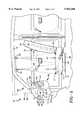
- FIG. 1is a schematic diagram of an occupant restraint assembly within a vehicle showing the vehicle occupant sensing apparatus of this invention when no objects or occupants are present.
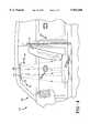
- FIG. 2is a schematic diagram similar to that shown in FIG. 1 but showing the vehicle occupant sensing apparatus of this invention with a back facing child seat on the seat of the vehicle.
- FIG. 3is a schematic diagram similar to that shown in FIG. 1 but showing the vehicle occupant sensing apparatus of this invention with a front facing child seat on the seat of the vehicle.
- FIG. 4is a schematic diagram similar to that shown in FIG. 1 but showing ultrasonic range measurement systems that include independent transmitters and receivers.
- FIG. 5is a schematic diagram similar to that shown in FIG. 1 but showing the vehicle occupant sensing apparatus of this invention with an adult on the seat of the vehicle.
- FIG. 1shows the inside of a vehicle 10 with an occupant restraint assembly 20 that is equipped with the present invention, a vehicle occupant sensing apparatus 30.
- a vehicle occupant sensing apparatus 30Although the embodiments shown herein concern the front seat of a passenger car, it is to be understood that this invention is applicable to any seat in any vehicle and other applications as well. It should also be understood that the vehicle occupant sensing apparatus 30 of this invention works with any type of occupant restraint assembly such as an airbag or seat belt pretensioner or may be used without an occupant restraint assembly.
- the vehicle 10includes an instrument panel 11, a base 12 and a top 13.
- the vehicle 10also includes a seat 14 that has a seat cushion portion 15 and a back rest portion 16.
- the seat 14is connected to the base 12 of the vehicle 10 in any manner currently known in the art.
- the vehicle occupant sensing apparatus 30 of this inventionis applicable when the seat 14 is adjustably connected to the base 12.
- the seat 14can be moved along rails 24 as is commonly known in the art.
- the occupant restraint assembly 20includes an airbag 21 and an inflator 23 that is used to inflate the airbag 21.
- the airbag 21 in this exemplary embodimentis located within the instrument panel 11 of the vehicle 10.
- the precise operation of the airbag 21 and the inflator 23is known in the art and therefore will not be discussed in detail.
- the vehicle occupant sensing apparatus 30 of this inventionincludes first and second range measurement systems 31, 32 and a controller 40.
- the vehicle occupant sensing apparatus 30also includes a third range measurement system 36.
- the first range measurement system 31senses a first distance L1 from the first range measurement system 31 toward a first area 17 of the seat 14.
- the second range measurement system 32senses a second distance L2 from the second range measurement system 32 toward a second area 18 of the seat 14
- the third range measurement system 36senses a third distance L3 from the third range measurement system 36 toward a third area 19 of the seat 14.
- the first and second range measurement systemsare located above the first and second areas 17, 18 of the seat cushion portion 15 of the seat 14 and the third range measurement system 36 is located on the instrument panel 11 transverse to the back rest portion 16 of the seat 14.
- the first and second range measurement systems 31, 32are used to determine distances in a substantially vertical direction and that the third range measurement system 36 is used to determine distances in a substantially horizontal direction.
- the first, second and third range measurement systems 31, 32, 36are interfaced with the controller 40.
- the controller 40can be of any type chosen with sound engineering judgment that operates as discussed herein, such as an application specific integrated circuit (ASIC), a microprocessor, a microcontroller, or a combination of suitable electronic components.
- the controller 40includes operating means 41 for operating the first, second and third range measurements systems 31, 32, 36 and determining means 44 for determining if an object (not shown in FIG. 1) is located on the seat 14 based on the distances sensed by the first, second and third range measurements systems 31, 32, 36.
- the controller 40has the capability to vary the operation of the deployment of the airbag 21.
- a deployment interface 25operatively connects the controller 40 to the inflator 23.
- the operation of the occupant restraint assembly 20may be varied by any adjusting means 49 known in the art such as by disabling the inflator 23, varying the timing of the beginning of deployment, deploying more than one inflator and/or venting the gas (not shown) from the inflator 23 prior to its entry in the airbag 21.
- a crash sensor 50is operatively connected to the controller 40 via a crash sensor interface 51.
- the crash sensor 50can be of any type currently known in the art used in sensing a crash and therefor the need to deploy the airbag 21.
- the first, second, and third range measurement systems 31, 32, 36can be devices of any type chosen with sound engineering judgment such as infrared devices, microwave devices, radio wave generating devices and other types as well.
- the first, second, and third range measurement systems 31, 32, 36comprise ultrasonic devices.
- the ultrasonic devicescan be of any type chosen with sound engineering judgment but, in a prototype the devices employed, are Polaroid ultrasonic transducers/range modules, series 6500, part no. 615077. It is further preferred that the first, second and third range measurement systems, 31, 32, 36, shown in FIGS. 1-5, transmit waves that spread out into a conical pattern toward the seat 14 of the vehicle 10.
- first, second and third range measurement systems 31, 32, 36are ultrasonic devices that include a combination transmitter/receiver. This minimizes the number of components for this invention.
- first and second range measurement systems 81, 82include independent transmitters 82, 85 respectively and receivers 83, 86 respectively.
- the operation of the first and second range measurement systems 81, 84 of this embodimentoperate as the first and second range measurement systems 31, 32 shown in FIG. 1 and discussed above.
- the operating means 41 of the controller 40causes the first, second and third range measurement systems, 31, 32, 36 to begin transmitting ultrasonic waves toward the seat 14 as described above.
- the first, second and third distances L1, L2, L3 between any object or occupant on the seat 14 and the first, second and third range measurement systems, 31, 32, 36can be sensed.
- the adjusting means 49 of the controller 40can then adjust the occupant restraint assembly 20 accordingly in preparation for an impending crash should a crash be sensed by the crash sensor 50.
- the determining means 44 of the controller 40includes third distance determining means 47 for determining if the third distance L3 is less than a predetermined value.
- the predetermined valuecan be any distance chosen with sound engineering judgment that would establish that an object or an occupant is too close to the instrument panel 11 for the airbag 21 to be properly deployed.
- the exact predetermined valuemay vary but for illustrative purposes only it may be, for example, 15 centimeters.
- the determining means 44 of the controller 40also includes first and second distance determining means 45, 46 for determining if the first and second distances L1, L2 are within the range of an empty seat value and a head height value.
- the empty seat valuecan be any distance chosen with sound engineering judgment that would establish that the seat is empty, that is no object or occupant is present. The exact empty seat value will depend on the vehicle being used but for illustrative purposes only it may be, for example, 90 centimeters.
- the head height valuecan be any distance chosen with sound engineering judgment that would establish that on object or an occupant is present and that if it is an occupant, the occupant is not a small child.
- This valueis called a head height value because if an occupant is present, the head of the occupant would be sensed first.
- the exact head height valuewill depend on the vehicle being used but for illustrative purposes only it may be, for example, 60 centimeters.
- the operation of the vehicle occupant sensing apparatus 30will now be discussed in the case when no object or occupant is present on the seat 14 of the vehicle 10.
- the operating means 41 of the controller 40causes the first, second and third range measurement systems, 31, 32, 36 to begin transmitting ultrasonic waves toward the seat 14.
- the first, second and third distances L1, L2, L3are sensed.
- the third distance determining means 47would determine that the third distance L3 is not less than a predetermined value. In other words, no object or occupant is too close to the instrument panel 11 for the airbag 21 to be properly deployed.
- the first and second distance determining means 45, 46would determine that the first and second distances L1, L2 are equal or greater than the empty seat value. In other words, no object or occupant is present. Thus, in this case, the adjusting means 49 would preferably disable the inflator 23 so that the airbag 21 cannot be deployed. There is no need to deploy the airbag 21 when no occupant is present in the seat 14.
- the operation of the vehicle occupant sensing apparatus 30will now be discussed in the case when an occupant 61 that is an adult is present on the seat 14 of the vehicle 10.
- adultit is meant any occupant that is of sufficient size to require the normal or full deployment strength for the airbag 21.
- the first distance determining means 45would determine that the first distance L1(b) is within the range of the empty seat value and the head height value.
- the second distance determining means 46would determine that the second distance L2(b) is equal to or less than the head height value.
- the first and second determining means 45, 46would determine that the occupant 61 is present and positioned in a "normal" position, that is leaning against the back rest portion 16 of the seat 14.
- the adjusting means 49would preferably adjust the occupant restraint assembly 20 so that the airbag 21 can be deployed at normal or full strength should deployment become necessary.
- the occupant 61could be positioned ore forwardly, that is toward the instrument panel 11, than shown in FIG. 5. This might occur if the occupant 61 was learning forward, for example.
- the first and second range measurement systems 31, 32would sense different distances and the first and second distance determining means 45, 46 would correspondingly determine that the occupant 61 was out of a normal position.
- the third distance determining means 47would likely determine that the third distance L3(b) is less than the predetermined value.
- the adjusting means 49would then preferably adjust the occupant restraint assembly 20 so that the airbag 21 could not be deployed or could be deployed according to only specific parameters.
- the operation of the vehicle occupant sensing apparatus 30will now be discussed in the case when an object 60 such as a child seat 62 that is back facing is positioned on the seat 14 of the vehicle 10.
- the child seat 62may contain an occupant 61 that is an infant or small child.
- the operating means 41 of the controller 40causes the first, second and third range measurement systems, 31, 32, 36 to begin transmitting ultrasonic waves toward the seat 14.
- the first, second and third distances L1(c), L2(c), L3(c)are sensed.
- the third distance determining means 47would determine that the third distance L3(c) is not less than a predetermined value.
- the first and second distance determining means 45, 46would determine that both the first and second distances L1(c), L2(c) are within the range of the empty seat value and the head height value. This is the condition that indicates a child seat may be present, that is the seat 14 is not empty but an adult occupant is not present.
- Child seats 62typically have first and second ends 63, 64 that have different heights. In particular for back facing child seats, such as the child seat 62 shown in FIG.
- the first end 63has a first height H1 that is greater than a second height H2 of the second end 64. This corresponds to the first distance L1(c) being smaller than the second distance L2(c).
- the determining means 44 of the controller 40determine a distance ratio equal to the first distance L1 divided by the second distance L2. If the distance ratio is less than 1, the first distance L1(c) is less than the second distance L2(c) and therefore the first height H1 of the first end 63 of the child seat 62 is greater than the second height H2 of the second end 64 of the child seat 62.
- the child seat 62is a back facing child seat.
- the adjusting means 49would then preferably disable the inflator 23 so that the airbag 21 could not be deployed. It should be noted that it does not matter if the first range measurement system 31 senses a distance from the head of the occupant 61 or the first end 63 of the child seat 62. The same determination would be made in either case. In addition, it should be noted that if the third distance determining means 47 determines that the third distance L3(c) is less than the predetermined value the adjusting means 49 would then preferably disable the inflator 23 so that the airbag 21 could not be deployed.
- the operation of the vehicle occupant sensing apparatus 30will now be discussed in the case when an object 60 such as a child seat 62 that is front facing is positioned on the seat 14 of the vehicle 10.
- the child seat 62may contain an occupant 61 that is an infant or small child.
- the operating means 41 of the controller 40causes the first, second and third range measurement systems, 31, 32, 36 to begin transmitting ultrasonic waves toward the seat 14.
- the first, second and third distances L1(d), L2(d), L3(d)are sensed.
- the third distance determining means 47would determine that the third distance L3(c) is not less than a predetermined value.
- the object 60is not too close to the instrument panel 11 for the airbag 21 to be properly deployed.
- the first and second distance determining means 45, 46would determine that both the first and second distances L1(d), L2(d) are within the range of the empty seat value and the head height value. This, as noted above, is the condition that indicates a child seat may be present.
- the first end 63has a first height H1 that is less than a second height H2 of the second end 64.
- the determining means 44 of the controller 40determine a distance ratio equal to the first distance L1 divided by the second distance L2. If the distance ratio is greater than 1, the first distance L1(d) is greater than the second distance L2(d) and therefore the first height H1 of the first end 63 of the child seat 62 is less than the second height H2 of the second end 64 of the child seat 62.
- the child seat 62is a front facing child seat.
- the adjusting means 49would then preferably adjust the occupant restraint assembly 20 so that the airbag 21 would either not deploy or deploy at a reduced strength.
- the operating means 41 of the controller 40includes first pulse rate operating means 42 for operating the first, second and third range measurement systems 31, 32, 36 at first pulse rates T1A, T2A, T3A respectively and second pulse rate operating means 43 for operating the first, second and third range measurement systems 31, 32, 36 at second pulse rates T1B, T2B, T3B respectively.
- the operating means 41can then switch from the first pulse rate operating means 42 to the second pulse rate operating means 43 in response to the first, second and third distances L1(b), L2(b), L3(b) sensed by the first, second and third range measurement systems 31, 32, 36.
- the determining means 44has determined that the occupant 61 is in a normal position, it is then preferred that the operating means 41 switch to a less frequent operation.
- the pulse rates of all the range measurement systemsmay be increased.
- the actual values for the first and second pulse rates T1A, T2A, T3A, T1B, T2B, T3Bcan be any chosen with sound engineering judgment. It may, for example, be desirable for any or all the second pulse rates T1B, T2B, T3B to be faster than any or all of the first pulse rates T1A, T2B, T3B.
- vehicle occupant sensing apparatus 30 of this inventionmay work independently as described above, it may also be used in an overall sensing system that may include other sensing criteria such as seat belt tension, seat occupant weight, seat position and the like.
Landscapes
- Engineering & Computer Science (AREA)
- Mechanical Engineering (AREA)
- Aviation & Aerospace Engineering (AREA)
- Transportation (AREA)
- Health & Medical Sciences (AREA)
- Child & Adolescent Psychology (AREA)
- General Health & Medical Sciences (AREA)
- Physics & Mathematics (AREA)
- Computer Networks & Wireless Communication (AREA)
- Radar, Positioning & Navigation (AREA)
- Remote Sensing (AREA)
- Acoustics & Sound (AREA)
- General Physics & Mathematics (AREA)
- Air Bags (AREA)
- Measurement Of Velocity Or Position Using Acoustic Or Ultrasonic Waves (AREA)
- Seats For Vehicles (AREA)
Abstract
Description
Claims (6)
Priority Applications (5)
| Application Number | Priority Date | Filing Date | Title |
|---|---|---|---|
| US08/933,596US5954360A (en) | 1997-09-18 | 1997-09-18 | Vehicle occupant sensing apparatus and method |
| EP98943451AEP1015279B1 (en) | 1997-09-18 | 1998-08-29 | Vehicle occupant sensing apparatus |
| PCT/US1998/017871WO1999014083A1 (en) | 1997-09-18 | 1998-08-29 | Vehicle occupant sensing apparatus |
| DE69825298TDE69825298T2 (en) | 1997-09-18 | 1998-08-29 | DEVICE FOR RECORDING VEHICLE INITIALS |
| JP2000511662AJP2003525153A (en) | 1997-09-18 | 1998-08-29 | Vehicle occupant sensing device |
Applications Claiming Priority (1)
| Application Number | Priority Date | Filing Date | Title |
|---|---|---|---|
| US08/933,596US5954360A (en) | 1997-09-18 | 1997-09-18 | Vehicle occupant sensing apparatus and method |
Publications (1)
| Publication Number | Publication Date |
|---|---|
| US5954360Atrue US5954360A (en) | 1999-09-21 |
Family
ID=25464217
Family Applications (1)
| Application Number | Title | Priority Date | Filing Date |
|---|---|---|---|
| US08/933,596Expired - Fee RelatedUS5954360A (en) | 1997-09-18 | 1997-09-18 | Vehicle occupant sensing apparatus and method |
Country Status (5)
| Country | Link |
|---|---|
| US (1) | US5954360A (en) |
| EP (1) | EP1015279B1 (en) |
| JP (1) | JP2003525153A (en) |
| DE (1) | DE69825298T2 (en) |
| WO (1) | WO1999014083A1 (en) |
Cited By (48)
| Publication number | Priority date | Publication date | Assignee | Title |
|---|---|---|---|---|
| WO2000038956A1 (en)* | 1998-12-30 | 2000-07-06 | Automotive Systems Laboratory, Inc. | Occupant sensor |
| US6196575B1 (en)* | 1997-07-23 | 2001-03-06 | Trw Occupant Restraint Systems Gmbh & Co. Kg | Gas bag restraint system for vehicle occupants |
| US6199902B1 (en)* | 1999-02-12 | 2001-03-13 | Trw Inc. | Apparatus and method for discerning at least one occupant characteristic via absorption of an energy signal |
| US6220627B1 (en) | 1998-04-20 | 2001-04-24 | Automotive Systems Lab | Occupant detection system |
| US6253134B1 (en)* | 1995-06-07 | 2001-06-26 | Automotive Technologies International Inc. | Apparatus and methods for ascertaining the identity of objects in a vehicle and adjusting a vehicle component based thereon |
| US6255790B1 (en)* | 1996-11-21 | 2001-07-03 | Siemens Aktiengesellschaft | Vehicle seat with a control device |
| USRE37260E1 (en) | 1996-02-08 | 2001-07-03 | Automotive Technologies International Inc. | Method for identifying the presence and orientation of an object in a vehicle |
| US6275756B1 (en)* | 2000-06-21 | 2001-08-14 | Breed Automotive Technology, Inc. | Smart ignitor control system |
| US6290255B1 (en) | 1997-03-07 | 2001-09-18 | Automotive Systems Laboratory, Inc. | Occupant detection system |
| US6302438B1 (en)* | 1998-04-21 | 2001-10-16 | Automotive Systems Laboratory, Inc. | Occupant detection system |
| US6324453B1 (en)* | 1998-12-31 | 2001-11-27 | Automotive Technologies International, Inc. | Methods for determining the identification and position of and monitoring objects in a vehicle |
| US6325413B2 (en)* | 1997-11-17 | 2001-12-04 | Nec Corporation | Passenger detection system |
| US6341252B1 (en)* | 1999-12-21 | 2002-01-22 | Trw Inc. | Method and apparatus for controlling an actuatable occupant protection device |
| US6373146B2 (en)* | 1998-10-02 | 2002-04-16 | Kansei Corporation | Occupant protection apparatus |
| US6382667B1 (en)* | 1999-10-06 | 2002-05-07 | Takata Corporation | Passenger restraining protective apparatus |
| US6397136B1 (en) | 1997-02-06 | 2002-05-28 | Automotive Technologies International Inc. | System for determining the occupancy state of a seat in a vehicle |
| US6431592B2 (en)* | 1999-04-15 | 2002-08-13 | Robert Bosch Corporation | Linear ultrasound transducer array for an automotive occupancy sensor system |
| US6442465B2 (en) | 1992-05-05 | 2002-08-27 | Automotive Technologies International, Inc. | Vehicular component control systems and methods |
| US6445988B1 (en) | 1997-02-06 | 2002-09-03 | Automotive Technologies International Inc. | System for determining the occupancy state of a seat in a vehicle and controlling a component based thereon |
| US6447010B1 (en)* | 1999-06-30 | 2002-09-10 | Siemens Vdo Automotive Corporation | Seat belt force sensor system |
| US6452870B1 (en) | 1996-02-08 | 2002-09-17 | Automotive Technologies International, Inc. | Methods for controlling deployment of an occupant restraint in a vehicle and determining whether the occupant is a child seat |
| US20020140214A1 (en)* | 1992-05-05 | 2002-10-03 | Breed David S. | Occupant restraint device control system and method |
| US6507779B2 (en) | 1995-06-07 | 2003-01-14 | Automotive Technologies International, Inc. | Vehicle rear seat monitor |
| US6529809B1 (en) | 1997-02-06 | 2003-03-04 | Automotive Technologies International, Inc. | Method of developing a system for identifying the presence and orientation of an object in a vehicle |
| US6553296B2 (en)* | 1995-06-07 | 2003-04-22 | Automotive Technologies International, Inc. | Vehicular occupant detection arrangements |
| US6552550B2 (en) | 2000-09-29 | 2003-04-22 | Intelligent Mechatronic Systems, Inc. | Vehicle occupant proximity sensor |
| US6561543B1 (en)* | 1998-01-09 | 2003-05-13 | Toyota Jidosha Kabushiki Kaisha | Vehicular child seat detection system |
| US6581961B1 (en)* | 1999-12-17 | 2003-06-24 | Trw Vehicle Safety Systems Inc. | Deactivation of second stage of air bag inflator |
| US20030168838A1 (en)* | 1998-06-09 | 2003-09-11 | Breed David S. | Methods for controlling a system in a vehicle using a transmitting/receiving transducer and/or while compensating for thermal gradients |
| WO2004019263A1 (en)* | 2002-08-10 | 2004-03-04 | Robert Bosch Gmbh | Device for determining the age of a person by measuring pupil size |
| US6772057B2 (en) | 1995-06-07 | 2004-08-03 | Automotive Technologies International, Inc. | Vehicular monitoring systems using image processing |
| US20040202049A1 (en)* | 2001-03-16 | 2004-10-14 | Breed David S. | System and method for eliminating audible noise for ultrasonic transducers |
| US6820897B2 (en) | 1992-05-05 | 2004-11-23 | Automotive Technologies International, Inc. | Vehicle object detection system and method |
| US6825765B2 (en) | 1998-12-30 | 2004-11-30 | Automotive Systems Laboratory, Inc. | Occupant detection system |
| US6856873B2 (en)* | 1995-06-07 | 2005-02-15 | Automotive Technologies International, Inc. | Vehicular monitoring systems using image processing |
| US20050121885A1 (en)* | 2003-12-05 | 2005-06-09 | Elesys North America, Inc. | Vehicle occupant sensing system |
| EP1669251A1 (en)* | 2004-12-07 | 2006-06-14 | IEE INTERNATIONAL ELECTRONICS & ENGINEERING S.A. | Child seat detection system |
| US20060186651A1 (en)* | 2005-02-18 | 2006-08-24 | Takata Corporation | Detection system, informing system, actuation system and vehicle |
| US20070086624A1 (en)* | 1995-06-07 | 2007-04-19 | Automotive Technologies International, Inc. | Image Processing for Vehicular Applications |
| US7370883B2 (en) | 2002-06-03 | 2008-05-13 | Intelligent Mechatronic Systems, Inc. | Three dimensional occupant position sensor |
| US7467809B2 (en) | 1992-05-05 | 2008-12-23 | Automotive Technologies International, Inc. | Vehicular occupant characteristic determination system and method |
| US20100274449A1 (en)* | 2009-04-22 | 2010-10-28 | Toyota Motor Engineering & Manufacturing North America, Inc. | Occupant detection and imaging system |
| US20140175775A1 (en)* | 2012-12-05 | 2014-06-26 | GM Global Technology Operations LLC | Side airbag |
| US8820782B2 (en) | 1995-06-07 | 2014-09-02 | American Vehicular Sciences Llc | Arrangement for sensing weight of an occupying item in vehicular seat |
| US10328966B2 (en)* | 2017-06-12 | 2019-06-25 | Steering Solutions Ip Holding Corporation | Steering column adjustment assembly |
| US10405661B2 (en) | 2015-05-13 | 2019-09-10 | La Hair Consulting Group Gmbh | Detection of the occupation of a hair salon chair by a person |
| US10520601B2 (en)* | 2015-04-15 | 2019-12-31 | Audio Pixels Ltd. | Methods and systems for detecting at least the position of an object in space |
| US11932188B2 (en)* | 2021-12-30 | 2024-03-19 | Hyundai Motor Company | Airbag deployment system of vehicle and airbag deployment method thereof |
Families Citing this family (5)
| Publication number | Priority date | Publication date | Assignee | Title |
|---|---|---|---|---|
| DE102015006011B3 (en)* | 2015-05-13 | 2016-10-13 | La Hair Consulting Group Gmbh | Detecting the occupation of a barber chair by a person |
| US10112505B2 (en) | 2016-09-21 | 2018-10-30 | Intel Corporation | Occupant profiling system |
| US10434966B2 (en)* | 2016-10-26 | 2019-10-08 | Ford Global Technologies, Llc | Gap based airbag deployment |
| CN106364442A (en)* | 2016-11-29 | 2017-02-01 | 李森 | Warning device and method for detecting persons left in vehicle |
| CN117284174B (en)* | 2023-10-12 | 2024-06-04 | 欧颂科技(海南)有限公司 | Seating sensing method and system for child safety seat |
Citations (11)
| Publication number | Priority date | Publication date | Assignee | Title |
|---|---|---|---|---|
| US5330226A (en)* | 1992-12-04 | 1994-07-19 | Trw Vehicle Safety Systems Inc. | Method and apparatus for detecting an out of position occupant |
| US5366241A (en)* | 1993-09-30 | 1994-11-22 | Kithil Philip W | Automobile air bag system |
| US5398185A (en)* | 1990-04-18 | 1995-03-14 | Nissan Motor Co., Ltd. | Shock absorbing interior system for vehicle passengers |
| US5454591A (en)* | 1993-11-03 | 1995-10-03 | Trw Vehicle Safety Systems Inc. | Method and apparatus for sensing a rearward facing child restraining seat |
| US5490069A (en)* | 1993-04-15 | 1996-02-06 | Automotive Systems Laboratory, Inc. | Multiple-strategy crash discrimination system |
| US5605348A (en)* | 1993-11-03 | 1997-02-25 | Trw Vehicle Safety Systems Inc. | Method and apparatus for sensing a rearward facing child seat |
| US5626359A (en)* | 1993-12-02 | 1997-05-06 | Trw Vehicle Safety Systems, Inc. | Method and apparatus for controlling an actuatable restraining device in response to discrete control zones |
| US5636864A (en)* | 1994-12-20 | 1997-06-10 | Kabushiki Kaisha Tokai-Rika-Denki-Seisakusho | Air bag apparatus for a passenger seat |
| US5653462A (en)* | 1992-05-05 | 1997-08-05 | Automotive Technologies International, Inc. | Vehicle occupant position and velocity sensor |
| US5782485A (en)* | 1993-12-29 | 1998-07-21 | Sensor Technology Co., Ltd. | Actuating-judgment system for safety device for protecting occupant on front passenger seat |
| US5845000A (en)* | 1992-05-05 | 1998-12-01 | Automotive Technologies International, Inc. | Optical identification and monitoring system using pattern recognition for use with vehicles |
- 1997
- 1997-09-18USUS08/933,596patent/US5954360A/ennot_activeExpired - Fee Related
- 1998
- 1998-08-29DEDE69825298Tpatent/DE69825298T2/ennot_activeExpired - Fee Related
- 1998-08-29EPEP98943451Apatent/EP1015279B1/ennot_activeExpired - Lifetime
- 1998-08-29WOPCT/US1998/017871patent/WO1999014083A1/enactiveIP Right Grant
- 1998-08-29JPJP2000511662Apatent/JP2003525153A/ennot_activeWithdrawn
Patent Citations (12)
| Publication number | Priority date | Publication date | Assignee | Title |
|---|---|---|---|---|
| US5398185A (en)* | 1990-04-18 | 1995-03-14 | Nissan Motor Co., Ltd. | Shock absorbing interior system for vehicle passengers |
| US5653462A (en)* | 1992-05-05 | 1997-08-05 | Automotive Technologies International, Inc. | Vehicle occupant position and velocity sensor |
| US5845000A (en)* | 1992-05-05 | 1998-12-01 | Automotive Technologies International, Inc. | Optical identification and monitoring system using pattern recognition for use with vehicles |
| US5848802A (en)* | 1992-05-05 | 1998-12-15 | Automotive Technologies International, Inc. | Vehicle occupant position and velocity sensor |
| US5330226A (en)* | 1992-12-04 | 1994-07-19 | Trw Vehicle Safety Systems Inc. | Method and apparatus for detecting an out of position occupant |
| US5490069A (en)* | 1993-04-15 | 1996-02-06 | Automotive Systems Laboratory, Inc. | Multiple-strategy crash discrimination system |
| US5366241A (en)* | 1993-09-30 | 1994-11-22 | Kithil Philip W | Automobile air bag system |
| US5454591A (en)* | 1993-11-03 | 1995-10-03 | Trw Vehicle Safety Systems Inc. | Method and apparatus for sensing a rearward facing child restraining seat |
| US5605348A (en)* | 1993-11-03 | 1997-02-25 | Trw Vehicle Safety Systems Inc. | Method and apparatus for sensing a rearward facing child seat |
| US5626359A (en)* | 1993-12-02 | 1997-05-06 | Trw Vehicle Safety Systems, Inc. | Method and apparatus for controlling an actuatable restraining device in response to discrete control zones |
| US5782485A (en)* | 1993-12-29 | 1998-07-21 | Sensor Technology Co., Ltd. | Actuating-judgment system for safety device for protecting occupant on front passenger seat |
| US5636864A (en)* | 1994-12-20 | 1997-06-10 | Kabushiki Kaisha Tokai-Rika-Denki-Seisakusho | Air bag apparatus for a passenger seat |
Cited By (68)
| Publication number | Priority date | Publication date | Assignee | Title |
|---|---|---|---|---|
| US6442465B2 (en) | 1992-05-05 | 2002-08-27 | Automotive Technologies International, Inc. | Vehicular component control systems and methods |
| US6820897B2 (en) | 1992-05-05 | 2004-11-23 | Automotive Technologies International, Inc. | Vehicle object detection system and method |
| US20020140214A1 (en)* | 1992-05-05 | 2002-10-03 | Breed David S. | Occupant restraint device control system and method |
| US7467809B2 (en) | 1992-05-05 | 2008-12-23 | Automotive Technologies International, Inc. | Vehicular occupant characteristic determination system and method |
| US6942248B2 (en)* | 1992-05-05 | 2005-09-13 | Automotive Technologies International, Inc. | Occupant restraint device control system and method |
| US8820782B2 (en) | 1995-06-07 | 2014-09-02 | American Vehicular Sciences Llc | Arrangement for sensing weight of an occupying item in vehicular seat |
| US6253134B1 (en)* | 1995-06-07 | 2001-06-26 | Automotive Technologies International Inc. | Apparatus and methods for ascertaining the identity of objects in a vehicle and adjusting a vehicle component based thereon |
| US20070086624A1 (en)* | 1995-06-07 | 2007-04-19 | Automotive Technologies International, Inc. | Image Processing for Vehicular Applications |
| US6856873B2 (en)* | 1995-06-07 | 2005-02-15 | Automotive Technologies International, Inc. | Vehicular monitoring systems using image processing |
| US6553296B2 (en)* | 1995-06-07 | 2003-04-22 | Automotive Technologies International, Inc. | Vehicular occupant detection arrangements |
| US6507779B2 (en) | 1995-06-07 | 2003-01-14 | Automotive Technologies International, Inc. | Vehicle rear seat monitor |
| US6772057B2 (en) | 1995-06-07 | 2004-08-03 | Automotive Technologies International, Inc. | Vehicular monitoring systems using image processing |
| US7596242B2 (en) | 1995-06-07 | 2009-09-29 | Automotive Technologies International, Inc. | Image processing for vehicular applications |
| USRE37260E1 (en) | 1996-02-08 | 2001-07-03 | Automotive Technologies International Inc. | Method for identifying the presence and orientation of an object in a vehicle |
| US6459973B1 (en) | 1996-02-08 | 2002-10-01 | Automotive Technologies International, Inc. | Arrangements for detecting the presence or location of an object in a vehicle and for controlling deployment of a safety restraint |
| US6452870B1 (en) | 1996-02-08 | 2002-09-17 | Automotive Technologies International, Inc. | Methods for controlling deployment of an occupant restraint in a vehicle and determining whether the occupant is a child seat |
| US6255790B1 (en)* | 1996-11-21 | 2001-07-03 | Siemens Aktiengesellschaft | Vehicle seat with a control device |
| US6445988B1 (en) | 1997-02-06 | 2002-09-03 | Automotive Technologies International Inc. | System for determining the occupancy state of a seat in a vehicle and controlling a component based thereon |
| US6529809B1 (en) | 1997-02-06 | 2003-03-04 | Automotive Technologies International, Inc. | Method of developing a system for identifying the presence and orientation of an object in a vehicle |
| US6397136B1 (en) | 1997-02-06 | 2002-05-28 | Automotive Technologies International Inc. | System for determining the occupancy state of a seat in a vehicle |
| US6290255B1 (en) | 1997-03-07 | 2001-09-18 | Automotive Systems Laboratory, Inc. | Occupant detection system |
| US6196575B1 (en)* | 1997-07-23 | 2001-03-06 | Trw Occupant Restraint Systems Gmbh & Co. Kg | Gas bag restraint system for vehicle occupants |
| US6325413B2 (en)* | 1997-11-17 | 2001-12-04 | Nec Corporation | Passenger detection system |
| US6561543B1 (en)* | 1998-01-09 | 2003-05-13 | Toyota Jidosha Kabushiki Kaisha | Vehicular child seat detection system |
| US6220627B1 (en) | 1998-04-20 | 2001-04-24 | Automotive Systems Lab | Occupant detection system |
| US6302438B1 (en)* | 1998-04-21 | 2001-10-16 | Automotive Systems Laboratory, Inc. | Occupant detection system |
| US6856876B2 (en) | 1998-06-09 | 2005-02-15 | Automotive Technologies International, Inc. | Methods for controlling a system in a vehicle using a transmitting/receiving transducer and/or while compensating for thermal gradients |
| US20030168838A1 (en)* | 1998-06-09 | 2003-09-11 | Breed David S. | Methods for controlling a system in a vehicle using a transmitting/receiving transducer and/or while compensating for thermal gradients |
| US6373146B2 (en)* | 1998-10-02 | 2002-04-16 | Kansei Corporation | Occupant protection apparatus |
| US6520535B1 (en) | 1998-12-30 | 2003-02-18 | Automotive Systems Laboratory, Inc. | Occupant detection system |
| US6517106B1 (en) | 1998-12-30 | 2003-02-11 | Automotive Systems Laboratory, Inc. | Occupant detection system |
| US6577023B1 (en) | 1998-12-30 | 2003-06-10 | Automotive Systems Laboratory, Inc. | Occupant detection system |
| WO2000038956A1 (en)* | 1998-12-30 | 2000-07-06 | Automotive Systems Laboratory, Inc. | Occupant sensor |
| US6283504B1 (en)* | 1998-12-30 | 2001-09-04 | Automotive Systems Laboratory, Inc. | Occupant sensor |
| US6825765B2 (en) | 1998-12-30 | 2004-11-30 | Automotive Systems Laboratory, Inc. | Occupant detection system |
| WO2000038959A1 (en)* | 1998-12-30 | 2000-07-06 | Automotive Systems Laboratory, Inc. | Occupant detection system |
| US6324453B1 (en)* | 1998-12-31 | 2001-11-27 | Automotive Technologies International, Inc. | Methods for determining the identification and position of and monitoring objects in a vehicle |
| US6199902B1 (en)* | 1999-02-12 | 2001-03-13 | Trw Inc. | Apparatus and method for discerning at least one occupant characteristic via absorption of an energy signal |
| US6431592B2 (en)* | 1999-04-15 | 2002-08-13 | Robert Bosch Corporation | Linear ultrasound transducer array for an automotive occupancy sensor system |
| US6447010B1 (en)* | 1999-06-30 | 2002-09-10 | Siemens Vdo Automotive Corporation | Seat belt force sensor system |
| US6382667B1 (en)* | 1999-10-06 | 2002-05-07 | Takata Corporation | Passenger restraining protective apparatus |
| US6581961B1 (en)* | 1999-12-17 | 2003-06-24 | Trw Vehicle Safety Systems Inc. | Deactivation of second stage of air bag inflator |
| US6341252B1 (en)* | 1999-12-21 | 2002-01-22 | Trw Inc. | Method and apparatus for controlling an actuatable occupant protection device |
| US6275756B1 (en)* | 2000-06-21 | 2001-08-14 | Breed Automotive Technology, Inc. | Smart ignitor control system |
| US6552550B2 (en) | 2000-09-29 | 2003-04-22 | Intelligent Mechatronic Systems, Inc. | Vehicle occupant proximity sensor |
| US6693442B2 (en) | 2000-09-29 | 2004-02-17 | Intelligent Mechantronic Systems, Inc. | Vehicle occupant proximity sensor |
| US6693440B2 (en) | 2000-09-29 | 2004-02-17 | Intelligent Mechantronic Systems, Inc. | Vehicle occupant proximity seat sensor |
| US7079450B2 (en)* | 2001-03-16 | 2006-07-18 | Automotive Technologies International, Inc. | System and method for eliminating audible noise for ultrasonic transducers |
| US20040202049A1 (en)* | 2001-03-16 | 2004-10-14 | Breed David S. | System and method for eliminating audible noise for ultrasonic transducers |
| US7370883B2 (en) | 2002-06-03 | 2008-05-13 | Intelligent Mechatronic Systems, Inc. | Three dimensional occupant position sensor |
| US20060126901A1 (en)* | 2002-08-10 | 2006-06-15 | Bernhard Mattes | Device for determining the age of a person by measuring pupil size |
| WO2004019263A1 (en)* | 2002-08-10 | 2004-03-04 | Robert Bosch Gmbh | Device for determining the age of a person by measuring pupil size |
| US7151452B2 (en) | 2003-12-05 | 2006-12-19 | Elesys North America Inc. | Vehicle occupant sensing system |
| EP1550576A3 (en)* | 2003-12-05 | 2005-07-13 | Elesys North America Inc. | Vehicle occupant sensing system |
| US20050121885A1 (en)* | 2003-12-05 | 2005-06-09 | Elesys North America, Inc. | Vehicle occupant sensing system |
| WO2006061405A1 (en)* | 2004-12-07 | 2006-06-15 | Iee International Electronics & Engineering S.A. | Child seat detection system |
| EP1669251A1 (en)* | 2004-12-07 | 2006-06-14 | IEE INTERNATIONAL ELECTRONICS & ENGINEERING S.A. | Child seat detection system |
| US20090234542A1 (en)* | 2004-12-07 | 2009-09-17 | Iee International Electronics & Engineering S.A. | Child seat detection system |
| US8059867B2 (en)* | 2005-02-18 | 2011-11-15 | Takata Corporation | Detection system, informing system, actuation system and vehicle |
| US20060186651A1 (en)* | 2005-02-18 | 2006-08-24 | Takata Corporation | Detection system, informing system, actuation system and vehicle |
| US8260502B2 (en)* | 2009-04-22 | 2012-09-04 | Toyota Motor Engineering & Manufacturing North America, Inc. | Occupant detection and imaging system |
| US20100274449A1 (en)* | 2009-04-22 | 2010-10-28 | Toyota Motor Engineering & Manufacturing North America, Inc. | Occupant detection and imaging system |
| US20140175775A1 (en)* | 2012-12-05 | 2014-06-26 | GM Global Technology Operations LLC | Side airbag |
| US8991858B2 (en)* | 2012-12-05 | 2015-03-31 | GM Global Technology Operations LLC | Side airbag |
| US10520601B2 (en)* | 2015-04-15 | 2019-12-31 | Audio Pixels Ltd. | Methods and systems for detecting at least the position of an object in space |
| US10405661B2 (en) | 2015-05-13 | 2019-09-10 | La Hair Consulting Group Gmbh | Detection of the occupation of a hair salon chair by a person |
| US10328966B2 (en)* | 2017-06-12 | 2019-06-25 | Steering Solutions Ip Holding Corporation | Steering column adjustment assembly |
| US11932188B2 (en)* | 2021-12-30 | 2024-03-19 | Hyundai Motor Company | Airbag deployment system of vehicle and airbag deployment method thereof |
Also Published As
| Publication number | Publication date |
|---|---|
| EP1015279A4 (en) | 2000-12-06 |
| DE69825298T2 (en) | 2005-07-21 |
| WO1999014083A1 (en) | 1999-03-25 |
| EP1015279B1 (en) | 2004-07-28 |
| EP1015279A1 (en) | 2000-07-05 |
| DE69825298D1 (en) | 2004-09-02 |
| JP2003525153A (en) | 2003-08-26 |
Similar Documents
| Publication | Publication Date | Title |
|---|---|---|
| US5954360A (en) | Vehicle occupant sensing apparatus and method | |
| US5906393A (en) | Occupant restraint system and control method with variable sense, sample, and determination rates | |
| US6024378A (en) | Vehicle seat assembly including at least one occupant sensing system and method of making same | |
| EP0880442B1 (en) | Vehicle passenger sensing system and method | |
| JP2781745B2 (en) | A device for preventing the operation of a vehicle occupant restraint system | |
| US7467809B2 (en) | Vehicular occupant characteristic determination system and method | |
| US6869101B2 (en) | Airbag with bag mounted sensor | |
| US6942248B2 (en) | Occupant restraint device control system and method | |
| US5785347A (en) | Occupant sensing and crash behavior system | |
| US6014602A (en) | Motor vehicle occupant sensing systems | |
| EP0952933B1 (en) | Apparatus and method for adjusting a vehicle component | |
| JP3088064B2 (en) | Control device and control method for occupant restraint system | |
| US6199902B1 (en) | Apparatus and method for discerning at least one occupant characteristic via absorption of an energy signal | |
| US6196579B1 (en) | Rear impact occupant protection system | |
| US20030136600A1 (en) | Method and arrangement for obtaining and conveying information about occupancy of a vehicle | |
| WO1997030864A9 (en) | Vehicle passenger sensing system and method | |
| JPH03159838A (en) | Air-bag spreading timing control device | |
| JP3880771B2 (en) | Linearly arranged ultrasonic transducers for automotive occupancy sensor systems | |
| KR20020022721A (en) | Seat belt force sensor system | |
| US6311112B1 (en) | Occupant restraint system and method having smart process initiation control | |
| JP2003072441A (en) | Device to detect seat occupancy | |
| EP1031475A2 (en) | Protection system for rear impact crashes | |
| JPH1044921A (en) | Occupant detector | |
| KR200180956Y1 (en) | Airbag of automobile | |
| KR19990030615A (en) | Device and method for adjusting distance between airbag and passenger |
Legal Events
| Date | Code | Title | Description |
|---|---|---|---|
| AS | Assignment | Owner name:BREED AUTOMOTIVE TECHNOLOGY, INC., FLORIDA Free format text:ASSIGNMENT OF ASSIGNORS INTEREST;ASSIGNORS:PETTYPIECE, JR., ROBERT PERRY;GRIGGS III, JAMES WOODHOUSE;REEL/FRAME:008966/0915 Effective date:19971030 | |
| AS | Assignment | Owner name:CONGRESS FINANCIAL CORPORATION (FLORIDA), FLORIDA Free format text:SECURITY INTEREST;ASSIGNOR:BREED AUTOMOTIVE TECHNOLOGY, INC.;REEL/FRAME:011442/0646 Effective date:20001226 | |
| FPAY | Fee payment | Year of fee payment:4 | |
| AS | Assignment | Owner name:BREED AUTOMOTIVE TECHNOLOGY, INC., MICHIGAN Free format text:RELEASE OF SECURITY INTEREST IN TRADEMARKS;ASSIGNOR:CONGRESS FINANCIAL CORPORATION;REEL/FRAME:014313/0243 Effective date:20030725 | |
| AS | Assignment | Owner name:CITICORP USA, INC., AS TERM C LOAN COLLATERAL AGEN Free format text:SECURITY AGREEMENT;ASSIGNOR:BREED AUTOMOTIVE TECHNOLOGY, INC.;REEL/FRAME:014428/0283 Effective date:20030425 | |
| AS | Assignment | Owner name:KEY SAFETY SYSTEMS, INC., MICHIGAN Free format text:ASSIGNMENT OF ASSIGNORS INTEREST;ASSIGNOR:BREED AUTOMOTIVE TECHNOLOGY, INC.;REEL/FRAME:015361/0893 Effective date:20041116 | |
| REMI | Maintenance fee reminder mailed | ||
| LAPS | Lapse for failure to pay maintenance fees | ||
| STCH | Information on status: patent discontinuation | Free format text:PATENT EXPIRED DUE TO NONPAYMENT OF MAINTENANCE FEES UNDER 37 CFR 1.362 | |
| FP | Lapsed due to failure to pay maintenance fee | Effective date:20070921 |