US5954305A - Adaptable antenna mounting platform for fixed securement to an elongated mast pole - Google Patents
Adaptable antenna mounting platform for fixed securement to an elongated mast poleDownload PDFInfo
- Publication number
- US5954305A US5954305AUS08/929,207US92920797AUS5954305AUS 5954305 AUS5954305 AUS 5954305AUS 92920797 AUS92920797 AUS 92920797AUS 5954305 AUS5954305 AUS 5954305A
- Authority
- US
- United States
- Prior art keywords
- antenna
- mounting platform
- platform
- antenna mounting
- assembly
- Prior art date
- Legal status (The legal status is an assumption and is not a legal conclusion. Google has not performed a legal analysis and makes no representation as to the accuracy of the status listed.)
- Expired - Fee Related
Links
- 230000002093peripheral effectEffects0.000claimsabstractdescription12
- 229910000746Structural steelInorganic materials0.000claimsdescription19
- 239000002184metalSubstances0.000claimsdescription3
- 229910052751metalInorganic materials0.000claimsdescription3
- 238000009434installationMethods0.000description7
- 238000003466weldingMethods0.000description4
- XEEYBQQBJWHFJM-UHFFFAOYSA-NIronChemical compound[Fe]XEEYBQQBJWHFJM-UHFFFAOYSA-N0.000description2
- 230000000712assemblyEffects0.000description2
- 238000000429assemblyMethods0.000description2
- 230000005540biological transmissionEffects0.000description2
- 238000005520cutting processMethods0.000description2
- 238000004519manufacturing processMethods0.000description2
- 239000000463materialSubstances0.000description2
- 230000008054signal transmissionEffects0.000description2
- 238000013316zoningMethods0.000description2
- 229910000831SteelInorganic materials0.000description1
- 238000006243chemical reactionMethods0.000description1
- 230000009194climbingEffects0.000description1
- -1e.g.Substances0.000description1
- 230000000694effectsEffects0.000description1
- 229910052742ironInorganic materials0.000description1
- 238000005304joiningMethods0.000description1
- 230000002265preventionEffects0.000description1
- 239000010959steelSubstances0.000description1
Images


Classifications
- H—ELECTRICITY
- H01—ELECTRIC ELEMENTS
- H01Q—ANTENNAS, i.e. RADIO AERIALS
- H01Q1/00—Details of, or arrangements associated with, antennas
- H01Q1/12—Supports; Mounting means
- H01Q1/1242—Rigid masts specially adapted for supporting an aerial
Definitions
- This inventionrelates generally to antenna support platforms on elongated mast poles. More specifically, this invention relates to an adaptable antenna mounting platform for fixed securement to an elongated mast pole that allows for one or more antennae mounted thereon to be independently adjusted or tuned. This invention also relates to an adaptable antenna mounting platform that provides safety hand rails that are easily mounted to and removable from the platform by service personnel using conventional tools as may be required during installation, adjustment and removal of platform mounted antennae. Also, this invention relates to an antenna support platform that is adaptable to provide a low profile that is aesthetically pleasing and will not detract from the appearance of the location at which the communications pole is located.
- high mast platforms for mounting communications antennaeare usually designed with safety hand rails mounted thereon based upon a customer's request or in accordance with industry safety standards.
- the safety hand railsprovide a measure of safety to service personnel working on the platform in addition to their wearing safety harnesses tethered to the mast pole.
- such safety hand railsare permanently affixed to the platform by means of welding. Often, these safety hand rails act to obstruct service personnel working on the platform during the installation, adjustment or removal of antennae thereon. For example, often it is necessary to maneuver one or several large or bulky pieces of telecommunications equipment on the platform which cannot fit between inner and outer safety rails.
- the obstruction created by the safety hand railsmay jeopardize the safety of personnel working on the platform.
- service personnelmay often find it necessary to remove one or more safety handrails, or portions thereof, from the platform in order to obtain the necessary space to conduct necessary service work on the platform.
- such safety hand railsare removed by cutting using appropriate welding equipment.
- many in industry and the publichave considered the presence of such permanently mounted safety hand rails to detract from the aesthetic appearance of the location on which the high mast pole is located. Therefore, it may also be desirable to remove the safety hand rails from the platform to provide a more streamlined and visually appealing appearance that would be less objectionable and more acceptable to the public and zoning review boards.
- platform mounted antennaeare typically mounted to support structures that are welded directly to the platform. Often it becomes necessary for service personnel to adjust the position of these antennae in order to optimize the transmission or reception of signals. In order to make any adjustment to such platform mounted antennae, service personnel must cut the support structure on which the antenna is mounted from the platform using appropriate welding equipment, adjust the position of the antenna and reweld the support structure to the platform. This manner of adjusting platform mounted antennae is cumbersome. Moreover, where optimal signal transmission and reception are not initially achieved, it may be necessary to repeat the steps of cutting and rewelding the antenna support structures several times. Therefore, from a cost standpoint there has been a long-felt need by those in the public and those in the industry for a platform that eliminates the use of welded antenna support structures and that provides support structures that readily adjust to a variety of selectable locations to improve antenna performance.
- the antenna mounting platformfor mounting along the length of an elongated mast pole.
- the antenna mounting platformcomprises a frame assembly having a peripheral edge and an interior opening to enable access to the platform by service personnel.
- the frame assemblyincludes a walkway extending along the peripheral edge, the walkway having a width and an inner edge.
- the antenna mounting platformalso comprises at least one antenna support means arranged for supporting an antenna.
- the antenna support meansincludes a clamping means for slidably mounting the antenna support means to the peripheral edge of the frame assembly for locating the antenna support means at selectable positions along the peripheral edge of the frame.
- FIG. 1is an isometric view of the preferred embodiment of the present invention with only outer safety hand rails installed;
- FIG. 2is an isometric view of the preferred embodiment of the present invention with both the outer and inner safety hand rails installed;
- FIG. 3is a partial isometric view of a mounting bracket with associated hardware constructed in accordance with the present invention
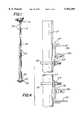
- FIG. 4is an enlarged sectional view taken along line 4--4 of FIG. 2; FIG.
- FIG. 5is a enlarged sectional view taken along line 5--5 of FIG. 2;
- FIG. 6is a partial isometric view of a mounting bracket with associated mounting hardware constructed in accordance with the present invention.
- FIG. 7is a partial isometric view of the preferred embodiment of the present invention with no safety hand rails attached;
- FIG. 8is a partial isometric view of a mounting bracket with associated mounting hardware constructed in accordance with the present invention.
- FIG. 9is an enlarged sectional view taken along line 9--9 of FIG. 7;
- FIG. 10is a partial exploded isometric view of a corner mounting bracket with associated mounting hardware constructed in accordance with the present invention.
- FIG. 11is an sectional view taken along line-11--11 of FIG. 2;
- FIG. 12is a partial exploded isometric view of a corner bracket with associated mounting hardware constructed in accordance with the present invention.
- FIG. 1the preferred embodiment of the adaptable antenna mounting platform constructed in accordance with this invention.
- the mast pole 15is a hollow member open at both ends and is provided with a horizontally disposed base flange 20 and a horizontally disposed top flange (not shown) welded thereto.
- the base flange 20is provided with through openings to facilitate attachment of the mast pole 15 to a concrete pad 25 by any conventional means known to those practiced in the art, e.g., attachment to bolts extending upwardly from the concrete pad 25.
- a safety cable 35extends the entire length of the mast pole 15 and is secured at its ends to the mast pole 15 by connection to flanges 40 disposed on the outer surface thereof at the top and bottom.
- Safety regulationsusually require service personnel climbing the mast pole or working on the platform 10 to wear a safety harness connected to a safety cable such as the one shown at 35 by means of a lanyard for the purpose of protecting against a fall from an elevated position on the mast pole where that person may have slipped.
- a safety harnessin combination with a safety cable is well known to those practiced in the art.
- the platform 10is shown mounted atop the mast pole 15.
- the platform 10 of the preferred embodimentcomprises a support frame 45 comprising a plurality of angle-iron pieces 50 and 75 that are oriented and joined end-to-end to form an outer triangle having three corner regions and a peripheral edge 53.
- Angle-iron pieces 80are joined together end-to-end and to angle-iron pieces 75 to form an inner triangle.
- the inner trianglesurrounds a plurality of openings through which service personnel may climb to obtain access to the platform 10.
- FIG. 5best illustrates the manner in which angle-iron pieces 50 and 75 are joined and held together in each of the corner regions of the support frame 45.
- a vertical support member 100is disposed on the outside surface of the angle-iron pieces 50 and an angle bracket 57 is disposed over the outside surface of the vertical support member 100, all being secured together using conventional hardware 58, e.g., nuts, bolts and washers.
- Angleiron pieces 75are also shown in FIG. 5 as being held together with conventional hardware 58. It is important to mention at this juncture that the shape of the platform 10 shown in FIG. 2 is merely exemplary and the platform 10 does not necessarily have to be triangular in shape.
- a plurality of elongated sheets 85 formed of metal gradinglie over the angle-iron pieces 50, 75 and 80 to form a deck. The deck provides a walkway surface on which service personnel may work during mounting, adjustment or removal of platform mounted antennae.
- the platform 10additionally comprises a mounting plate 54 that is generally triangular in shape and may be fabricated from a galvanized metal, such as sheet steel or other suitable material.
- the mounting plate 54is provided with a centrally located opening 60 through which cables (not shown), connected to platform mounted antennae (not shown), pass for connection with telecommunications equipment (not shown) normally positioned at ground level.
- the mounting plate 54is also provided with a plurality of slotted through openings 65, to enable attachment of the platform 10 to horizontally disposed flanges (not shown) welded at the top of the mast pole 15 by any conventional means, e.g., nuts, bolts and washers.
- the through openings 65 in the mounting plate 54are slotted to enable rotation of the platform 10 in order to achieve precise spatial orientation of the antennae mounted thereon so as to obtain optimal transmission and reception of signals.
- each channel segment 55is joined to the mounting plate 54 by any suitable material, e.g., iron.
- each channel segment 55is joined to the mounting plate 54 by any conventional means known to those practiced in the art, e.g., nuts, bolts and washers.
- each channel segment 55is affixed to an angle-iron piece 50 about midway along the length thereof also by conventional means known to those practiced in the art.
- a chimney 70is secured to the top surface of the mounting plate 54 by means of L-shaped flanges 76 welded to the plate.
- the chimney 70protects the interior of the mast pole from weather elements such as rain and snow.
- the chimney 70is provided with an eyebolt 71 attached thereto. Once service personnel have climbed onto the platform 10, they may connect their safety harnesses to the eyebolt 71 as a means for fall prevention.
- the adaptable antenna mounting platform 10is shown therein as having an inner safety hand rail assembly 90 and an outer safety hand rail assembly 95 mounted thereon.
- the outer hand rail assembly 95comprises a plurality of cross-members 105 formed of angle-iron pieces that are secured together end-to-end by attachment to upright support members 100 and angle brackets 57 using conventional hardware 58, e.g., nuts, bolts and washers.
- the cross-members 105are shown in FIG. 2 as forming a triangular shape, however, it should be understood that this shape is merely exemplary.
- the inner safety hand rail assembly 90is assembled to the platform using angle brackets in a similar manner.
- antenna support tubes 117mount to the platform 10 by means of adjustable brackets 118 and 119; the adjustable bracket 118 mounting the support tube 117 to a cross-member 105 and the adjustable bracket 119 mounting the support tube 117 to an angle-iron piece 50.
- the adjustable bracket 118is shaped to fit over the angle-iron piece 50 and the adjustable bracket 119 is shaped to fit over cross-member 105.
- the bracket 118aBy tightening on bolt 118a, the bracket 118 may be fixedly secured to the angle-iron 50.
- the bracket 119may be fixedly secured to the cross-member 105.
- brackets 118 and 119may be simultaneously slid to selectable positions along angle-iron 50 and cross-member 105, respectively, to enable adjustment of the position of the antenna support tube 117 and antennae mounted thereon.
- the antenna support tubes 117are held to brackets 118 and 119 by means of threaded U-bolts 121 and associated conventional hardware 123, e.g., nuts and washers, thus facilitating installation and removal of antenna support tubes 117 to and from brackets 118 and 119.
- antenna support tubes 117may be mounted in each corner region of the platform 10.
- the corner brackets 57further comprise a mounting plate 59 which is arranged for attachment of the antenna support tubes 117 thereto using conventional attachment hardware, e.g., threaded U-bolts 121, nuts 125 and washers.
- conventional attachment hardwaree.g., threaded U-bolts 121, nuts 125 and washers.
- FIGS. 11 and 12there is shown therein an angular upright member 142 for joining cross-members 105 end-to-end using conventional hardware 143, e.g., nuts, bolts and washers.
- the angular upright member 142 shown in FIGS. 11 and 12does not provide a means for supporting antenna support tubes thereon.
- both safety hand rail assemblies 90 and 95in place as shown in FIG. 2, the platform 10 is said to have a standard profile. Provision of both the safety hand rail assemblies 90 and 95 on the platform 10 serves to improve the safety of service personnel working on the platform 10 at heights exceeding one-hundred fifty feet.
- one or both of the safety hand railsmay act as an obstruction to service personnel working on the platform 10.
- the inner safety hand rail assembly 90 or a portion thereofmay be easily removed from the platform 10 by use of an adjustable wrench.
- FIG. 1the platform 10 of the present invention is shown with the inner safety hand rail 90 removed and the outer safety hand rail remaining in place.
- adjustable brackets 131may be utilized for mounting of antenna support tubes 117.
- the adjustable brackets 131are shaped to fit over angle-iron piece 50. By tightening on associated hardware 131a, e.g., nut and bolt, the bracket 131 may be fixedly secured to the angle-iron 50.
- the bracket 131may be slid to selectable positions along angle-iron 50 to enable adjustment of the position of the antenna support tube 117 and antennae (not shown) mounted thereon.
- the antenna support tube 117is held to the bracket 131 by means of a pair of threaded U-bolts 121 and associated conventional hardware 123, e.g., nuts and washers, thus facilitating installation and removal of antenna support tubes 117 to and from the bracket 131 without the necessity to remove the bracket 131 from the angle-iron 50.
- the angle-iron pieces 50 and 75may be joined together in each of the corner regions of the frame 45 using an angle bracket 153 and conventional hardware 155, e.g., nuts, bolts and washers.
- the angle bracket 153further comprises a mounting plate 157 having through holes which is arranged for attachment of the antenna support tubes 117 thereon by use of threaded U-bolts 121, nuts and washers 123.
- the mounting plate 157is shown in FIG. 10 as having rounded through holes for mounting, these mounting holes could also be horizontally slotted to enable horizontal adjustment of the U-bolts 121 and antenna support tubes 117 mounted thereon.
Landscapes
- Support Of Aerials (AREA)
Abstract
Description
Claims (20)
Priority Applications (1)
| Application Number | Priority Date | Filing Date | Title |
|---|---|---|---|
| US08/929,207US5954305A (en) | 1997-09-09 | 1997-09-09 | Adaptable antenna mounting platform for fixed securement to an elongated mast pole |
Applications Claiming Priority (1)
| Application Number | Priority Date | Filing Date | Title |
|---|---|---|---|
| US08/929,207US5954305A (en) | 1997-09-09 | 1997-09-09 | Adaptable antenna mounting platform for fixed securement to an elongated mast pole |
Publications (1)
| Publication Number | Publication Date |
|---|---|
| US5954305Atrue US5954305A (en) | 1999-09-21 |
Family
ID=25457484
Family Applications (1)
| Application Number | Title | Priority Date | Filing Date |
|---|---|---|---|
| US08/929,207Expired - Fee RelatedUS5954305A (en) | 1997-09-09 | 1997-09-09 | Adaptable antenna mounting platform for fixed securement to an elongated mast pole |
Country Status (1)
| Country | Link |
|---|---|
| US (1) | US5954305A (en) |
Cited By (51)
| Publication number | Priority date | Publication date | Assignee | Title |
|---|---|---|---|---|
| US6115004A (en)* | 1998-11-13 | 2000-09-05 | Mcginnis; Henry J. | Antenna support system |
| US6193436B1 (en)* | 1998-12-03 | 2001-02-27 | Rand Display, Inc. | Locking system for supporting element |
| EP1158599A1 (en)* | 2000-05-18 | 2001-11-28 | Pfleiderer Infrastrukturtechnik GmbH & Co. KG | Device for fastening an antenna on antenna mast platforms |
| US6452566B1 (en) | 2001-11-21 | 2002-09-17 | Dieceland Technologies Corp. | Antenna construction for wireless telephonic communications systems and method |
| US6492959B1 (en)* | 1999-10-22 | 2002-12-10 | Andrew Corporation | Stacked array antenna system |
| WO2003009416A1 (en)* | 2001-07-19 | 2003-01-30 | Pirod, Inc. | Rotatable platform for lattice towers |
| US20030048233A1 (en)* | 2000-01-17 | 2003-03-13 | Schotman Willem Yvo | Mast for a source of electromagnetic waves, provided with a stabilisation device |
| US6563475B2 (en) | 2000-10-13 | 2003-05-13 | Pirod, Inc. | Antenna mount |
| US6561473B1 (en) | 2001-03-30 | 2003-05-13 | Pirod, Inc. | Universal pipe mounting clamp and assembly |
| BE1014739A3 (en)* | 2002-04-02 | 2004-03-02 | Den Eynden Gregor Van | Ladder for antenna mast, has steps formed by protruding parts joined to U shaped supports in anchors on mast |
| US20040094681A1 (en)* | 2002-08-08 | 2004-05-20 | Ulrich Birnbaum | Bracket element |
| US6766992B1 (en)* | 2003-04-24 | 2004-07-27 | The United States Of America As Represented By The Secretary Of The Navy | Mounting bracket for attachment to flat or cylindrical surfaces |
| US20040226227A1 (en)* | 2003-05-13 | 2004-11-18 | Johnson Carrie P. | Extendable aerial service wire mast |
| US20050001782A1 (en)* | 2003-07-01 | 2005-01-06 | Andrew Corporation | Multiple Antenna Configuration and support structure |
| US20060287835A1 (en)* | 2004-07-19 | 2006-12-21 | Sheth Pradip N | Inspection system of structures and equipment and related method thereof |
| US20070272641A1 (en)* | 2006-05-26 | 2007-11-29 | Magic Ad Production Co. Ltd. | Multipurpose stereoscopic display shelf |
| EP1513715A4 (en)* | 2002-06-14 | 2009-04-15 | Hexagon Technology As | Method and apparatus for mounting a fluid containment cylinder |
| US20110176938A1 (en)* | 2010-01-19 | 2011-07-21 | Defilippis Michael S | Torsional restraint for jet pump assembly |
| US20110279347A1 (en)* | 2010-05-17 | 2011-11-17 | Kenwood Telecom Corporation | Platform assemblies for radio transmission towers |
| US20120228461A1 (en)* | 2009-11-13 | 2012-09-13 | Telefonaktiebolaget Lm Ericsson (Publ) | Antenna Mast Arrangement |
| US8302736B1 (en) | 2007-09-28 | 2012-11-06 | Integris Rentals, L.L.C. | Containment work platform with protruding connection |
| US20120291833A1 (en)* | 2011-05-20 | 2012-11-22 | Art Hand | Tower Mounting Apparatus |
| US20130233983A1 (en)* | 2012-03-07 | 2013-09-12 | Debra Kay Adams | Variable orientation antenna platform |
| ITMI20121386A1 (en)* | 2012-08-03 | 2014-02-04 | Irte Spa | TOWER FOR TELECOMMUNICATIONS PROVIDED WITH A WORK PLATFORM AND WORK PLATFORM FOR A TOWER FOR TELECOMMUNICATIONS |
| US8938930B2 (en)* | 2011-12-12 | 2015-01-27 | Charles Larue Bryant, JR. | Support apparatus for wellbore tools |
| US20150218830A1 (en)* | 2014-02-03 | 2015-08-06 | Progress Rail Services Corporation | System and method for connecting platform |
| US20160298804A1 (en)* | 2015-04-07 | 2016-10-13 | Stellenbosch University | Frame supported height adjustable pylon |
| US20160298310A1 (en)* | 2015-03-11 | 2016-10-13 | 4D Tech Solutions, Inc. | Pile repair clamp |
| US9689233B2 (en)* | 2014-06-30 | 2017-06-27 | Cameron International Corporation | Platform to service a blowout preventer |
| US20170343156A1 (en)* | 2016-05-31 | 2017-11-30 | Sabre Communications Corporation | Monopole platform upper rail support |
| US10072465B1 (en)* | 2013-03-15 | 2018-09-11 | Integris Rentals, L.L.C. | Containment work platform |
| US20180283110A1 (en)* | 2017-03-31 | 2018-10-04 | Schlumberger Technology Corporation | Multi-level deck system for blowout preventers |
| US10132098B1 (en)* | 2017-05-16 | 2018-11-20 | Atc Ip Llc | Non-disruptive reinforcement of telecommunications towers |
| US20190071859A1 (en)* | 2017-09-01 | 2019-03-07 | Urban Solution Group, LLC | Perimeter wall for an industrial worksite |
| US10246845B2 (en) | 2015-03-11 | 2019-04-02 | 4D Tech Solutions, Inc. | Pile repair apparatus |
| US20200123790A1 (en)* | 2018-10-23 | 2020-04-23 | Commscope Technologies Llc | High capacity platforms and cage mount assemblies |
| US10851596B2 (en) | 2017-11-30 | 2020-12-01 | Saudi Arabian Oil Company | Multi-level wellhead support platform |
| US11371326B2 (en) | 2020-06-01 | 2022-06-28 | Saudi Arabian Oil Company | Downhole pump with switched reluctance motor |
| US20220311121A1 (en)* | 2021-03-24 | 2022-09-29 | Commscope Technologies Llc | Telecommunications mounting frames and methods of making same |
| US11499563B2 (en) | 2020-08-24 | 2022-11-15 | Saudi Arabian Oil Company | Self-balancing thrust disk |
| US20230007369A1 (en)* | 2019-09-27 | 2023-01-05 | Commscope Technologies Llc | Ballasted telecommunications equipment mounts and assemblies |
| US11591899B2 (en) | 2021-04-05 | 2023-02-28 | Saudi Arabian Oil Company | Wellbore density meter using a rotor and diffuser |
| US11644351B2 (en) | 2021-03-19 | 2023-05-09 | Saudi Arabian Oil Company | Multiphase flow and salinity meter with dual opposite handed helical resonators |
| US20230228115A1 (en)* | 2022-01-20 | 2023-07-20 | Ashraf Radi | Reinforcing of tower base in existing guyed Towers |
| US11913464B2 (en) | 2021-04-15 | 2024-02-27 | Saudi Arabian Oil Company | Lubricating an electric submersible pump |
| US11920469B2 (en) | 2020-09-08 | 2024-03-05 | Saudi Arabian Oil Company | Determining fluid parameters |
| US11994016B2 (en) | 2021-12-09 | 2024-05-28 | Saudi Arabian Oil Company | Downhole phase separation in deviated wells |
| US12085687B2 (en) | 2022-01-10 | 2024-09-10 | Saudi Arabian Oil Company | Model-constrained multi-phase virtual flow metering and forecasting with machine learning |
| US12116788B1 (en)* | 2019-06-07 | 2024-10-15 | Valmont Industries, Inc. | Adjustable tower work platform for a monopole |
| USD1076892S1 (en)* | 2023-01-30 | 2025-05-27 | Kabushiki Kaisha Tokai Rika Denki | Antenna |
| US12381307B2 (en)* | 2021-09-24 | 2025-08-05 | Outdoor Wireless Networks LLC | Mounting assembly and method of use thereof |
Citations (9)
| Publication number | Priority date | Publication date | Assignee | Title |
|---|---|---|---|---|
| US3318561A (en)* | 1965-05-12 | 1967-05-09 | Antenna Specialists Co | Antenna support bracket |
| US4729532A (en)* | 1985-04-23 | 1988-03-08 | Billy Moss | Safety valve anchoring device |
| US5029799A (en)* | 1990-03-02 | 1991-07-09 | Roy Telecommunications Lt'ee | Downtilt support bracket for mounting an antenna on a metallic tower |
| US5097647A (en)* | 1990-11-09 | 1992-03-24 | Canadian Communications Structures Inc. | Support tower for communications equipment |
| US5274888A (en)* | 1993-04-05 | 1994-01-04 | Gto, Inc. | Adjustable U-bolt type pipe clamp |
| US5467955A (en)* | 1994-07-28 | 1995-11-21 | Bellsouth Corporation | Antenna mounting platform for a monopole tower |
| US5533304A (en)* | 1995-04-11 | 1996-07-09 | Pi-Rod, Inc. | Adjustable antenna support |
| US5557656A (en)* | 1992-03-06 | 1996-09-17 | Aircell, Inc. | Mobile telecommunications for aircraft and land based vehicles |
| US5649402A (en)* | 1995-09-01 | 1997-07-22 | Fwt, Inc. | Antenna support for power transmission tower |
- 1997
- 1997-09-09USUS08/929,207patent/US5954305A/ennot_activeExpired - Fee Related
Patent Citations (9)
| Publication number | Priority date | Publication date | Assignee | Title |
|---|---|---|---|---|
| US3318561A (en)* | 1965-05-12 | 1967-05-09 | Antenna Specialists Co | Antenna support bracket |
| US4729532A (en)* | 1985-04-23 | 1988-03-08 | Billy Moss | Safety valve anchoring device |
| US5029799A (en)* | 1990-03-02 | 1991-07-09 | Roy Telecommunications Lt'ee | Downtilt support bracket for mounting an antenna on a metallic tower |
| US5097647A (en)* | 1990-11-09 | 1992-03-24 | Canadian Communications Structures Inc. | Support tower for communications equipment |
| US5557656A (en)* | 1992-03-06 | 1996-09-17 | Aircell, Inc. | Mobile telecommunications for aircraft and land based vehicles |
| US5274888A (en)* | 1993-04-05 | 1994-01-04 | Gto, Inc. | Adjustable U-bolt type pipe clamp |
| US5467955A (en)* | 1994-07-28 | 1995-11-21 | Bellsouth Corporation | Antenna mounting platform for a monopole tower |
| US5533304A (en)* | 1995-04-11 | 1996-07-09 | Pi-Rod, Inc. | Adjustable antenna support |
| US5649402A (en)* | 1995-09-01 | 1997-07-22 | Fwt, Inc. | Antenna support for power transmission tower |
Cited By (74)
| Publication number | Priority date | Publication date | Assignee | Title |
|---|---|---|---|---|
| US6115004A (en)* | 1998-11-13 | 2000-09-05 | Mcginnis; Henry J. | Antenna support system |
| US6193436B1 (en)* | 1998-12-03 | 2001-02-27 | Rand Display, Inc. | Locking system for supporting element |
| US6492959B1 (en)* | 1999-10-22 | 2002-12-10 | Andrew Corporation | Stacked array antenna system |
| US20030048233A1 (en)* | 2000-01-17 | 2003-03-13 | Schotman Willem Yvo | Mast for a source of electromagnetic waves, provided with a stabilisation device |
| US6795036B2 (en)* | 2000-01-17 | 2004-09-21 | Koninklijke Kpn N.V. | Mast for a source of electromagnetic waves, provided with a stabilization device |
| EP1158599A1 (en)* | 2000-05-18 | 2001-11-28 | Pfleiderer Infrastrukturtechnik GmbH & Co. KG | Device for fastening an antenna on antenna mast platforms |
| US6563475B2 (en) | 2000-10-13 | 2003-05-13 | Pirod, Inc. | Antenna mount |
| US6561473B1 (en) | 2001-03-30 | 2003-05-13 | Pirod, Inc. | Universal pipe mounting clamp and assembly |
| US6710751B2 (en) | 2001-07-19 | 2004-03-23 | Pirod, Inc. | Rotatable platform for lattice towers |
| WO2003009416A1 (en)* | 2001-07-19 | 2003-01-30 | Pirod, Inc. | Rotatable platform for lattice towers |
| US6452566B1 (en) | 2001-11-21 | 2002-09-17 | Dieceland Technologies Corp. | Antenna construction for wireless telephonic communications systems and method |
| BE1014739A3 (en)* | 2002-04-02 | 2004-03-02 | Den Eynden Gregor Van | Ladder for antenna mast, has steps formed by protruding parts joined to U shaped supports in anchors on mast |
| EP1513715A4 (en)* | 2002-06-14 | 2009-04-15 | Hexagon Technology As | Method and apparatus for mounting a fluid containment cylinder |
| US20040094681A1 (en)* | 2002-08-08 | 2004-05-20 | Ulrich Birnbaum | Bracket element |
| US6766992B1 (en)* | 2003-04-24 | 2004-07-27 | The United States Of America As Represented By The Secretary Of The Navy | Mounting bracket for attachment to flat or cylindrical surfaces |
| US7712264B2 (en)* | 2003-05-13 | 2010-05-11 | At&T Intellectual Property I, L.P. | Extendable aerial service wire mast |
| US20040226227A1 (en)* | 2003-05-13 | 2004-11-18 | Johnson Carrie P. | Extendable aerial service wire mast |
| US20050001782A1 (en)* | 2003-07-01 | 2005-01-06 | Andrew Corporation | Multiple Antenna Configuration and support structure |
| US6956539B2 (en) | 2003-07-01 | 2005-10-18 | Electronics Research, Inc. | Multiple antenna configuration and support structure |
| US20060287835A1 (en)* | 2004-07-19 | 2006-12-21 | Sheth Pradip N | Inspection system of structures and equipment and related method thereof |
| US20070272641A1 (en)* | 2006-05-26 | 2007-11-29 | Magic Ad Production Co. Ltd. | Multipurpose stereoscopic display shelf |
| US10214969B1 (en)* | 2007-09-28 | 2019-02-26 | Integris Rentals, L.L.C. | Containment work platform with protruding connection |
| US8302736B1 (en) | 2007-09-28 | 2012-11-06 | Integris Rentals, L.L.C. | Containment work platform with protruding connection |
| US9540908B1 (en)* | 2007-09-28 | 2017-01-10 | Integris Rentals, L.L.C. | Containment work platform with protruding connection |
| US20120228461A1 (en)* | 2009-11-13 | 2012-09-13 | Telefonaktiebolaget Lm Ericsson (Publ) | Antenna Mast Arrangement |
| US8550791B2 (en) | 2010-01-19 | 2013-10-08 | Ge-Hitachi Nuclear Energy Americas Llc | Torsional restraint for jet pump assembly |
| US20110176938A1 (en)* | 2010-01-19 | 2011-07-21 | Defilippis Michael S | Torsional restraint for jet pump assembly |
| EP2400164A1 (en)* | 2010-01-19 | 2011-12-28 | GE-Hitachi Nuclear Energy Americas LLC | Torsional restraint for jet pump assembly |
| US20110279347A1 (en)* | 2010-05-17 | 2011-11-17 | Kenwood Telecom Corporation | Platform assemblies for radio transmission towers |
| US9385413B2 (en)* | 2010-05-17 | 2016-07-05 | Kenwood Telecom Corporation | Platform assemblies for radio transmission towers |
| US10170818B2 (en) | 2010-05-17 | 2019-01-01 | Kenwood Telecom Corporation | Platform assemblies for radio transmission towers |
| US20190123419A1 (en)* | 2010-05-17 | 2019-04-25 | Kenwood Telecom Corporation | Platform assemblies for radio transmission towers |
| US8641002B2 (en)* | 2011-05-20 | 2014-02-04 | Art Hand | Tower mounting apparatus |
| US20120291833A1 (en)* | 2011-05-20 | 2012-11-22 | Art Hand | Tower Mounting Apparatus |
| US8938930B2 (en)* | 2011-12-12 | 2015-01-27 | Charles Larue Bryant, JR. | Support apparatus for wellbore tools |
| US9118106B2 (en)* | 2012-03-07 | 2015-08-25 | Verizon Patent And Licensing Inc. | Variable orientation antenna platform |
| US20130233983A1 (en)* | 2012-03-07 | 2013-09-12 | Debra Kay Adams | Variable orientation antenna platform |
| ITMI20121386A1 (en)* | 2012-08-03 | 2014-02-04 | Irte Spa | TOWER FOR TELECOMMUNICATIONS PROVIDED WITH A WORK PLATFORM AND WORK PLATFORM FOR A TOWER FOR TELECOMMUNICATIONS |
| US10072465B1 (en)* | 2013-03-15 | 2018-09-11 | Integris Rentals, L.L.C. | Containment work platform |
| US10738539B1 (en)* | 2013-03-15 | 2020-08-11 | Integris Rentals, L.L.C. | Containment work platform |
| US20150218830A1 (en)* | 2014-02-03 | 2015-08-06 | Progress Rail Services Corporation | System and method for connecting platform |
| US9689233B2 (en)* | 2014-06-30 | 2017-06-27 | Cameron International Corporation | Platform to service a blowout preventer |
| US20160298310A1 (en)* | 2015-03-11 | 2016-10-13 | 4D Tech Solutions, Inc. | Pile repair clamp |
| US9903085B2 (en)* | 2015-03-11 | 2018-02-27 | 4D Tech Solutions, Inc. | Pile repair clamp |
| US10246845B2 (en) | 2015-03-11 | 2019-04-02 | 4D Tech Solutions, Inc. | Pile repair apparatus |
| US20160298804A1 (en)* | 2015-04-07 | 2016-10-13 | Stellenbosch University | Frame supported height adjustable pylon |
| US9995427B2 (en)* | 2015-04-07 | 2018-06-12 | Stellenbosch University | Frame supported height adjustable pylon |
| US20170343156A1 (en)* | 2016-05-31 | 2017-11-30 | Sabre Communications Corporation | Monopole platform upper rail support |
| US10526803B2 (en)* | 2016-05-31 | 2020-01-07 | Sabre Communications Corporation | Monopole platform upper rail support |
| US20180283110A1 (en)* | 2017-03-31 | 2018-10-04 | Schlumberger Technology Corporation | Multi-level deck system for blowout preventers |
| US10494890B2 (en)* | 2017-03-31 | 2019-12-03 | Schlumberger Technology Corporation | Multi-level deck system for blowout preventers |
| US10132098B1 (en)* | 2017-05-16 | 2018-11-20 | Atc Ip Llc | Non-disruptive reinforcement of telecommunications towers |
| US10519684B2 (en) | 2017-05-16 | 2019-12-31 | Atc Ip Llc | Non-disruptive reinforcement of telecommunications towers |
| US11767666B2 (en) | 2017-09-01 | 2023-09-26 | Urban Solution Group, LLC | Articulated perimeter wall for an industrial worksite |
| US20190071859A1 (en)* | 2017-09-01 | 2019-03-07 | Urban Solution Group, LLC | Perimeter wall for an industrial worksite |
| US10767362B2 (en)* | 2017-09-01 | 2020-09-08 | Urban Solution Group, LLC | Articulated perimeter wall for an industrial worksite |
| US10851596B2 (en) | 2017-11-30 | 2020-12-01 | Saudi Arabian Oil Company | Multi-level wellhead support platform |
| US20200123790A1 (en)* | 2018-10-23 | 2020-04-23 | Commscope Technologies Llc | High capacity platforms and cage mount assemblies |
| US12116788B1 (en)* | 2019-06-07 | 2024-10-15 | Valmont Industries, Inc. | Adjustable tower work platform for a monopole |
| US20230007369A1 (en)* | 2019-09-27 | 2023-01-05 | Commscope Technologies Llc | Ballasted telecommunications equipment mounts and assemblies |
| US11937027B2 (en)* | 2019-09-27 | 2024-03-19 | Commscope Technologies Llc | Ballasted telecommunications equipment mounts and assemblies |
| US11371326B2 (en) | 2020-06-01 | 2022-06-28 | Saudi Arabian Oil Company | Downhole pump with switched reluctance motor |
| US11499563B2 (en) | 2020-08-24 | 2022-11-15 | Saudi Arabian Oil Company | Self-balancing thrust disk |
| US11920469B2 (en) | 2020-09-08 | 2024-03-05 | Saudi Arabian Oil Company | Determining fluid parameters |
| US11644351B2 (en) | 2021-03-19 | 2023-05-09 | Saudi Arabian Oil Company | Multiphase flow and salinity meter with dual opposite handed helical resonators |
| US12046795B2 (en)* | 2021-03-24 | 2024-07-23 | Commscope Technologies Llc | Telecommunications mounting frames and methods of making same |
| US20220311121A1 (en)* | 2021-03-24 | 2022-09-29 | Commscope Technologies Llc | Telecommunications mounting frames and methods of making same |
| US11591899B2 (en) | 2021-04-05 | 2023-02-28 | Saudi Arabian Oil Company | Wellbore density meter using a rotor and diffuser |
| US11913464B2 (en) | 2021-04-15 | 2024-02-27 | Saudi Arabian Oil Company | Lubricating an electric submersible pump |
| US12381307B2 (en)* | 2021-09-24 | 2025-08-05 | Outdoor Wireless Networks LLC | Mounting assembly and method of use thereof |
| US11994016B2 (en) | 2021-12-09 | 2024-05-28 | Saudi Arabian Oil Company | Downhole phase separation in deviated wells |
| US12085687B2 (en) | 2022-01-10 | 2024-09-10 | Saudi Arabian Oil Company | Model-constrained multi-phase virtual flow metering and forecasting with machine learning |
| US20230228115A1 (en)* | 2022-01-20 | 2023-07-20 | Ashraf Radi | Reinforcing of tower base in existing guyed Towers |
| USD1076892S1 (en)* | 2023-01-30 | 2025-05-27 | Kabushiki Kaisha Tokai Rika Denki | Antenna |
Similar Documents
| Publication | Publication Date | Title |
|---|---|---|
| US5954305A (en) | Adaptable antenna mounting platform for fixed securement to an elongated mast pole | |
| US10170818B2 (en) | Platform assemblies for radio transmission towers | |
| US5641141A (en) | Antenna mounting system | |
| US20040020158A1 (en) | Tower apparatus | |
| US7175140B2 (en) | Mounting apparatus and method for use with a tile roof | |
| US20210123263A1 (en) | Vertical cable rail barrier | |
| US20100327140A1 (en) | Method for Use of Easy Set-Up Pole and Support System | |
| US8015759B1 (en) | Structural mounting for equipment on a rooftop | |
| US5221076A (en) | Protective device and method of installing protective device | |
| US20130213306A1 (en) | Pole top extension accessories and methods of using same | |
| US4459649A (en) | Pole mounted lighting system | |
| US11495872B2 (en) | Single point heavy duty monopole platform | |
| US6167988B1 (en) | Lineman's ladder stabilizer | |
| EP3695458B1 (en) | Adjustable antenna mounting system | |
| US9822528B1 (en) | Bicycle shelter assembly | |
| CA2646798A1 (en) | Apparatus and method for securing fall arrest equipment | |
| EP1160395A2 (en) | Device in guard railings | |
| US7003816B1 (en) | Fence system for an above-the-ground swimming pool | |
| JP3241196B2 (en) | Equipment mounting table | |
| KR100868912B1 (en) | Antenna mount for communication | |
| JP4511869B2 (en) | Lightning rod device | |
| JP2007159537A (en) | Apparatus for preventing nesting | |
| AU783587B2 (en) | Fall arrest anchor point | |
| WO1996011352A1 (en) | Antenna mounting system | |
| AU784389B2 (en) | Scaffolding apparatus |
Legal Events
| Date | Code | Title | Description |
|---|---|---|---|
| AS | Assignment | Owner name:SUMMIT MANUFACTURING, INC., PENNSYLVANIA Free format text:ASSIGNMENT OF ASSIGNORS INTEREST;ASSIGNOR:CALABRO, FRANCIS C.;REEL/FRAME:008997/0620 Effective date:19970912 | |
| AS | Assignment | Owner name:IBJ WHITEHALL BANK & TRUST COMPANY, NEW YORK Free format text:SECURITY INTEREST;ASSIGNOR:SUMMIT MANUFACTURING, LLC;REEL/FRAME:011763/0593 Effective date:20010412 | |
| AS | Assignment | Owner name:IBJ WHITEHALL BANK & TRUST COMPANY, AS ADMINISTRAT Free format text:SECURITY AGREEMENT;ASSIGNOR:SUMMIT MANUFACTURING, LLC;REEL/FRAME:011862/0538 Effective date:20010412 Owner name:IBJ WHITEHALL BANK & TRUST COMPANY AS ADMINISTRATI Free format text:SECURITY INTEREST;ASSIGNOR:SUMMIT MANUFACTURING, LLC;REEL/FRAME:011862/0542 Effective date:20010412 | |
| AS | Assignment | Owner name:NEW SUMMIT MANUFACTURING, L.L.C., PENNSYLVANIA Free format text:ASSIGNMENT OF ASSIGNORS INTEREST;ASSIGNOR:SUMMIT MANUFACTURING, LLC;REEL/FRAME:013403/0093 Effective date:20020904 | |
| FPAY | Fee payment | Year of fee payment:4 | |
| REMI | Maintenance fee reminder mailed | ||
| LAPS | Lapse for failure to pay maintenance fees | ||
| STCH | Information on status: patent discontinuation | Free format text:PATENT EXPIRED DUE TO NONPAYMENT OF MAINTENANCE FEES UNDER 37 CFR 1.362 | |
| FP | Lapsed due to failure to pay maintenance fee | Effective date:20070921 |