US5953900A - Closed loop steam cooled steam turbine - Google Patents
Closed loop steam cooled steam turbineDownload PDFInfo
- Publication number
- US5953900A US5953900AUS08/715,773US71577396AUS5953900AUS 5953900 AUS5953900 AUS 5953900AUS 71577396 AUS71577396 AUS 71577396AUS 5953900 AUS5953900 AUS 5953900A
- Authority
- US
- United States
- Prior art keywords
- flow
- steam
- turbine
- cooling steam
- cooling
- Prior art date
- Legal status (The legal status is an assumption and is not a legal conclusion. Google has not performed a legal analysis and makes no representation as to the accuracy of the status listed.)
- Expired - Lifetime
Links
Images


Classifications
- F—MECHANICAL ENGINEERING; LIGHTING; HEATING; WEAPONS; BLASTING
- F02—COMBUSTION ENGINES; HOT-GAS OR COMBUSTION-PRODUCT ENGINE PLANTS
- F02C—GAS-TURBINE PLANTS; AIR INTAKES FOR JET-PROPULSION PLANTS; CONTROLLING FUEL SUPPLY IN AIR-BREATHING JET-PROPULSION PLANTS
- F02C7/00—Features, components parts, details or accessories, not provided for in, or of interest apart form groups F02C1/00 - F02C6/00; Air intakes for jet-propulsion plants
- F02C7/12—Cooling of plants
- F02C7/16—Cooling of plants characterised by cooling medium
- F—MECHANICAL ENGINEERING; LIGHTING; HEATING; WEAPONS; BLASTING
- F01—MACHINES OR ENGINES IN GENERAL; ENGINE PLANTS IN GENERAL; STEAM ENGINES
- F01K—STEAM ENGINE PLANTS; STEAM ACCUMULATORS; ENGINE PLANTS NOT OTHERWISE PROVIDED FOR; ENGINES USING SPECIAL WORKING FLUIDS OR CYCLES
- F01K25/00—Plants or engines characterised by use of special working fluids, not otherwise provided for; Plants operating in closed cycles and not otherwise provided for
- F—MECHANICAL ENGINEERING; LIGHTING; HEATING; WEAPONS; BLASTING
- F01—MACHINES OR ENGINES IN GENERAL; ENGINE PLANTS IN GENERAL; STEAM ENGINES
- F01D—NON-POSITIVE DISPLACEMENT MACHINES OR ENGINES, e.g. STEAM TURBINES
- F01D25/00—Component parts, details, or accessories, not provided for in, or of interest apart from, other groups
- F01D25/08—Cooling; Heating; Heat-insulation
- F01D25/12—Cooling
- F—MECHANICAL ENGINEERING; LIGHTING; HEATING; WEAPONS; BLASTING
- F01—MACHINES OR ENGINES IN GENERAL; ENGINE PLANTS IN GENERAL; STEAM ENGINES
- F01K—STEAM ENGINE PLANTS; STEAM ACCUMULATORS; ENGINE PLANTS NOT OTHERWISE PROVIDED FOR; ENGINES USING SPECIAL WORKING FLUIDS OR CYCLES
- F01K25/00—Plants or engines characterised by use of special working fluids, not otherwise provided for; Plants operating in closed cycles and not otherwise provided for
- F01K25/005—Plants or engines characterised by use of special working fluids, not otherwise provided for; Plants operating in closed cycles and not otherwise provided for the working fluid being steam, created by combustion of hydrogen with oxygen
- F—MECHANICAL ENGINEERING; LIGHTING; HEATING; WEAPONS; BLASTING
- F05—INDEXING SCHEMES RELATING TO ENGINES OR PUMPS IN VARIOUS SUBCLASSES OF CLASSES F01-F04
- F05D—INDEXING SCHEME FOR ASPECTS RELATING TO NON-POSITIVE-DISPLACEMENT MACHINES OR ENGINES, GAS-TURBINES OR JET-PROPULSION PLANTS
- F05D2260/00—Function
- F05D2260/20—Heat transfer, e.g. cooling
- F05D2260/232—Heat transfer, e.g. cooling characterized by the cooling medium
- F05D2260/2322—Heat transfer, e.g. cooling characterized by the cooling medium steam
- Y—GENERAL TAGGING OF NEW TECHNOLOGICAL DEVELOPMENTS; GENERAL TAGGING OF CROSS-SECTIONAL TECHNOLOGIES SPANNING OVER SEVERAL SECTIONS OF THE IPC; TECHNICAL SUBJECTS COVERED BY FORMER USPC CROSS-REFERENCE ART COLLECTIONS [XRACs] AND DIGESTS
- Y02—TECHNOLOGIES OR APPLICATIONS FOR MITIGATION OR ADAPTATION AGAINST CLIMATE CHANGE
- Y02E—REDUCTION OF GREENHOUSE GAS [GHG] EMISSIONS, RELATED TO ENERGY GENERATION, TRANSMISSION OR DISTRIBUTION
- Y02E20/00—Combustion technologies with mitigation potential
- Y02E20/16—Combined cycle power plant [CCPP], or combined cycle gas turbine [CCGT]
- Y—GENERAL TAGGING OF NEW TECHNOLOGICAL DEVELOPMENTS; GENERAL TAGGING OF CROSS-SECTIONAL TECHNOLOGIES SPANNING OVER SEVERAL SECTIONS OF THE IPC; TECHNICAL SUBJECTS COVERED BY FORMER USPC CROSS-REFERENCE ART COLLECTIONS [XRACs] AND DIGESTS
- Y02—TECHNOLOGIES OR APPLICATIONS FOR MITIGATION OR ADAPTATION AGAINST CLIMATE CHANGE
- Y02T—CLIMATE CHANGE MITIGATION TECHNOLOGIES RELATED TO TRANSPORTATION
- Y02T50/00—Aeronautics or air transport
- Y02T50/60—Efficient propulsion technologies, e.g. for aircraft
Definitions
- the present inventionrelates to a turbine for use in a power plant using hydrogen and oxygen as the fuel. More specifically, the present invention relates to a closed loop steam cooled turbine in which steam, generated by the combustion of hydrogen and oxygen, is expanded for power generation.
- a gas turbineis typically comprised of a compressor section that produces compressed air, a combustion section that transforms the compressed air into a hot, compressed gas, and a turbine section that expands the hot, compressed gas.
- a hydrocarbon fuelsuch as distillate oil or natural gas
- combustorsUnfortunately, such combustion results in the formation of oxides of nitrogen (“NOx”), considered an atmospheric pollutant.
- Combusting hydrogen in pure oxygenwould eliminate all NOx formation.
- Combustors for rocket engineshave traditionally operated by combusting liquid hydrogen in liquid oxygen.
- power turbinesmust operate for extended periods of time without deterioration. Consequently, the problems of cooling the combustor in a gas turbine presents challenges not present in rocket combustors. This problem is exacerbated if, for reasons of economy and ease of handling and supply, compressed oxygen gas, rather than liquid oxygen, is used.
- rocket combustorsrely on the low temperature of liquid oxygen for cooling.
- Cooling of the turbine sectionwould also be a problem in a hydrogen/oxygen fueled power plant, especially since it is desirable to operate the turbine with inlet temperatures as high as 900 to 1600° C. in order to achieve optimum power output.
- the air cooling traditionally used in combustion turbinesnegatively impacts the efficiency of the power plant.
- this objectis accomplished in a method of generating rotating shaft power, comprising the steps of (i) combusting a first flow of hydrogen and a first flow of oxygen, thereby producing a first flow of steam, (ii) at least partially expanding the first flow of steam in a first turbine so as to produce shaft power and a flow of expanded steam, the first turbine having a plurality of components therein over which the first flow of steam flows, whereby heat is transferred from the first flow of steam to the components, (iii) transferring heat from the flow of expanded steam to a flow of feed water so as to generate a flow of cooling steam, (iv) directing at least a first portion of the flow of cooling steam through at least a first portion of the turbine components and transferring heat from the first portion of the turbine components to the first portion of the flow of cooling steam, thereby generating a first flow of heated cooling steam, and (v) mixing with the first flow of heated cooling steam with the first flow of steam.
- the inventionalso encompasses a power plant, comprising (i) a combustor having means for receiving and combusting a flow of hydrogen and flow of oxygen so as to produce a first flow of steam, (ii) a first turbine having means for expanding the first flow of steam so as to produce a flow of expanded steam, the expanding means including a plurality of components over which the first flow of steam flows and to which the first flow of steam transfers heat, (iii) means for transferring heat from the flow of expanded steam to a flow of feed water so as to generate a second flow of steam, (iv) means for directing at least a first portion of the second flow of steam through at least a first portion of the turbine components and for transferring heat from the first portion of the turbine components to the first portion of second flow of steam, thereby generating a first flow of heated steam, and (v) means for directing the first flow of heated steam to the combustor for mixing with the first flow of steam.
- FIG. 1is a schematic diagram of a hydrogen/oxygen fueled power plant employing the closed loop steam cooled high and intermediate pressure turbines according to the current invention.
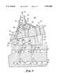
- FIG. 2is a longitudinal cross-section, partially schematic, through the high pressure turbine shown in FIG. 1.
- FIG. 3is an enlarged view of FIG. 2 in the vicinity of the turbine inlet.
- FIG. 1a hydrogen fueled power plant.
- the major components of the plantare a high pressure combustor 2, a high pressure steam turbine 12 through which a rotor 16 extends, an intermediate pressure combustor 4, and intermediate pressure steam turbine 14, a heat recovery steam generator 18, a low pressure steam turbine 20, and a condenser 22.
- each of the turbinesdrives a load, such as an electrical generator (not shown).
- hydrogen 6 and oxygen 8which may be in either gaseous or liquid--i.e., cryogenic--form, are supplied to the high pressure combustor 2. If the hydrogen 6 and oxygen 8 are in gaseous form, compressors may be utilized to further pressurized the gas. In the high pressure combustor 2, the hydrogen 6 and oxygen 8 combust to form high temperature, high pressure steam. Preferably, the combustion takes place at close to stoichiometric conditions so that the combustor 2 discharges essentially pure steam. A supply of temperature moderating steam 47, generated as discussed below, is also supplied to the high pressure combustor 2.
- the temperature moderating steam 47mixes with the steam produced by the combustion of the hydrogen 6 and oxygen 8, thereby cooling it and preventing overheating of the combustor 2 components.
- the steam mixture 50 discharged from the high pressure combustor 2is about 1600 ° and 250 bar.
- the steam 50is directed to the high pressure steam turbine 12, which is discussed in detail below.
- the steam 50is partially expanded, thereby producing shaft power in the rotor 16.
- the steam 48 discharged from the high pressure turbine 12has been expanded to 935° C. and 25 bar.
- the steam 48is then mixed with three streams of temperature moderating steam 43, 46, and 78.
- Steam 43has been heated in the process of cooling the intermediate pressure rows of vanes in the high pressure turbine 12, as discussed further below.
- Steam 46has been heated in the process of cooling the intermediate pressure turbine 14.
- Steam 78has been heated in the process of cooling the low pressure rows of blades in the high pressure turbine 12, as discussed further below.
- Additional hydrogen 7 and oxygen 9are combusted in the intermediate pressure combustor 4.
- the steam flows 43, 46, and 78are nevertheless cooler than the steam produced by the combustion of hydrogen 7 and oxygen 9 in the intermediate pressure combustor 4.
- steam streams 43, 48, 78, and 46are directed to the intermediate pressure combustor 4 and serve to moderate temperature and cool the combustor.
- the steam 43 and 46is approximately 650° C.
- the heated steam 52 discharged from the intermediate combustor 4is then directed to the intermediate steam turbine 14.
- the steam 52has been heated in the combustor 4 to approximately 1600° C.
- the steam 52is further expanded, thereby producing additional shaft power.
- the steam 54 discharged from the intermediate pressure turbine 14has been expanded to approximately 840° C. and 1 bar.
- the steam 54 from the intermediate turbine 14is then directed to a hear recovery steam generator 18, where a portion of its heat is transferred to two streams of feed water 102 and 104, thereby generating two streams of steam 30 and 58.
- sufficient heatis transferred in the heat recovery steam generator 18 so that the steam 60 discharged therefrom has been cooled to approximately 110° C.
- the cooled steam 60is directed to a low pressure turbine 20, where it is further expanded to produce still more shaft power.
- the steam 62 discharged from the low pressure turbine 20has been expanded to approximately 33° C. and 0.05 bar. The expanded steam 62 is then condensed in a condenser 22.
- the condensate 100 drawn from the condenser 22 by pump 23is split into three steams, the first and second of which are directed to feed pumps 24 and 25, respectively.
- the third stream 103is bleed from the cycle, as discussed below.
- Feed pump 24boosts the pressure of a portion of the condensate 100, preferably to a pressure in excess of 300 bar, and directs the high pressure feed water 102 to the heat recovery steam generator 18 where, as previously discussed, it absorbs heat from the steam 54 discharged by the intermediate pressure turbine 14.
- sufficient heatis transferred to heat the high pressure steam 30 discharged from the heat recovery steam generator 18 to approximately 400° C.
- Feed pump 25boosts the pressure of the second condensate stream to an intermediate pressure and directs the intermediate pressure feed water 104 to the heat recovery steam generator 18 where it is converted to intermediate pressure steam 58.
- intermediate steam 58is approximately 375° C. and 30 bar.
- the high pressure steam 30 from the heat recovery steam generator 18is split into two streams 32 and 34.
- Steam 34forms a portion of the temperature moderating steam 47 for the high pressure combustor 2, as previously discussed.
- steam 32is further split into two streams 35 and 36, both of which are directed to the high pressure turbine 12 for cooling.
- the first stream of cooling steam 35serves to cool the stationary vanes while the second stream of cooling steam 36 cools the rotor 16, as discussed further below.
- the vane cooling steam 35is divided into three streams 38, 39, and 40.
- Steam streams 38, 39, and 40serve to cool the high, intermediate and low pressure vanes of the high pressure turbine 12, respectively, and, in the process become further heated. After they perform their cooling function, steam streams 38, 39 and 40 are discharged from the turbine 12 as heated steam streams 44, 42, and 43, respectively.
- the high pressure vane cooling steam 44 that is discharged from the high pressure turbine 12forms a second portion of the temperature moderating steam 47 supplied to the high pressure combustor 2.
- the intermediate pressure vane cooling steam 42 that is discharged from the high pressure turbine 12is combined with the intermediate pressure steam 58 produced by the heat recovery steam generator 18, as previously discussed.
- the combined flow of steam 56is then directed to the intermediate pressure turbine 14 for cooling of the turbine components using the techniques discussed below with reference to the cooling of the high pressure turbine 12.
- the cooling steam 46which has preferably been heated to approximately 650° C., along with the high pressure turbine low pressure vane cooling steam 43, is combined with the steam 48 discharged from the high pressure turbine 12 so as to form the remainder of the temperature moderating steam for the intermediate pressure combustor 4.
- the second stream of cooling steam 36cools the blades of the high pressure turbine rotor 16, after which it is discharged from the rotor in two streams 78 and 45.
- Stream 78which cooled the lower pressure blades of the high pressure turbine 12, is combined with the low pressure vane cooling steam 43, where it serves to moderate the temperature in the intermediate pressure combustor 4, as previously discussed.
- Stream 45which cooled the high pressure blades of the high pressure turbine 12, is combined with the high pressure vane cooling steam 44 and forms the third portion of the temperature moderating steam 47 supplied to the high pressure combustor 2.
- all of the cooling of the high pressure turbine 12is accomplished by the steam 32, thereby providing a very thermodynamically efficient system.
- the cooling systemis closed loop--that is, except for incidental leakages, all of the steam 32 supplied to the high pressure turbine 12 for cooling is returned to the cycle, along with heat absorbed during the cooling. Since hydrogen and oxygen are continually added to the system in the combustors 2 and 4, a portion 103 of the condensate 100 is continuously bleed from the system to maintain an equilibrium.
- the high pressure turbine 12is enclosed by an outer shell 17 that encloses an inner shell 19.
- the inner and outer shells 17 and 19are connected by webs so as to form three plenums 120, 122 and 124 that serve to direct the flow of the cooling steam flows 38, 39 and 40, respectively.
- the high pressure combustors 2are attached to the front end of the outer shell 17.
- Ducts 126extend through plenum 120 and direct the flow of the steam 50 from the high pressure combustors 2 to the inlet of the turbine working fluid flow path.
- the high pressure vane cooling steam 38enters the outer shell 17 through a passage 110 and is directed by a pipe 141 to a circumferentially extending pipe 142, as shown in FIG. 3.
- Pipe 142forms a manifold 140 that divides the cooling steam 38 into three streams 64, 65, and 66 and distributes these streams to pipes 144, 146, and 148.
- each cooling passage 170has a simple U-shaped configuration.
- the cooling passages 170can take a variety of forms, such as serpentine.
- a portion of the heat that was transferred from the combustion steam 50 to the vanes 180is transferred from the vanes 180 to the cooling steam 64, thereby cooling the vanes and heating the cooling steam.
- the now heated cooling steam 67is directed by passages 152 to the plenum 120.
- pipes 146 and 148direct steam 65 and 66, respectively, from the manifold 140 to passages 154 and 158, respectively, formed in the inner shell 19.
- the passages 154 and 158direct the steam to passages 174 and 178, respectively, formed in the second and third rows of stationary vanes 182 and 184, respectively, thereby cooling the vanes.
- the now heated cooling steam 68 and 69 from the cooling passages 174 and 178, respectively,is the directed by passages 156 and 160, respectively, formed in the inner shell 19, to the plenum 120.
- the combined flow 44 of heated cooling steam 67, 68, and 69is directed by the plenum past the ducts 126 and into the high pressure combustors 2 where, as previously discussed, the steam 44 serves to moderate temperature and cool the combustors.
- the cooling steam 39 for the intermediate pressure vanes of the high pressure turbine 12enters the outer shell 17 through a passage 112 and is directed by a pipe to a circumferentially extending pipe that forms a manifold located within the plenum 122.
- the manifolddivides the cooling steam 39 into two streams 70 and 71 that are then distributed to pipes that direct them to passages in the inner shell 19 and eventually to cooling passages in the fourth and fifth row stationary vanes. Additional passages formed in the inner shell 19 direct the now heated cooling steam 72 and 73 from the vane cooling passages to the plenum 122.
- a passage 116 in the outer shell 17directs the heated cooling steam 42 out of the plenum 122.
- the heated intermediate pressure vane cooling steam 42is mixed with the steam 58 from the heat recovery steam generator 18 and then directed to the intermediate pressure turbine 14 where it provides further cooling.
- the cooling steam 40 for the low pressure vanes of the high pressure turbine 12enters the outer shell 17 through a passage 114 and is directed by a pipe to a circumferentially extending pipe that forms a manifold located within the plenum 124.
- the manifolddivides the cooling steam 40 into two streams 74 and 75 that are then distributed to pipes that direct them to passages in the inner shell 19 and eventually to cooling passages in the sixth and seventh row stationary vanes. Additional passages formed in the inner shell 19 direct the now heated cooling steam 76 and 77 from the vane cooling passages to the plenum 124.
- a gap 125 formed between an outer flow guide 128 and the inner shell 19directs the combined flow 43 of heated cooling steam streams 76 and 77 from the plenum 124 to the working fluid flow path where it mixes with the partially expanded steam 48 discharged from the high pressure turbine 12.
- cooling steam stream 43is subsequently further heated, and expanded steam stream 48 is subsequently reheated, in the intermediate pressure combustor 4.
- the portion 36 of the cooling steam 32 from the heat recovery steam generator 18enters the rotor 16 and flows axially upstream through a plurality of circumferentially distributed passages that form manifolds 130.
- the manifold 130could be a single circular annular passage. The manifolds 130 distribute the cooling steam 36 to each of the rows of blades in the rotor 16 of the high pressure turbine 12.
- each cooling passage 172has a simple U-shaped configuration.
- the cooling passages 172can take a variety of forms, such as serpentine.
- cooling steam 85 for the second row blades 188flows through passages 166 and bushings 192 to cooling passages 176 formed in the second row blades 188. Passages 168 direct the now heated cooling steam 93 to the manifold 134.
- cooling 84is provided to the third row blades. The combined flow 45 of heated cooling steam 92, 93, and 94 from the first three rows of blades is directed by the manifold 134 to the plenum 120.
- the high pressure blade cooling steam 45is directed, along with the high pressure vane cooling steam 44, by the plenum past the ducts 126 and into the high pressure combustors 2 where, as previously discussed, the steam streams 44 and 45 serve to moderate temperature.
- the rotor manifold 130also distributes steam flows 80-83 to the fourth through seventh rows of rotating blades.
- the streams of heated cooling steam 87-90 from these rowsis directed by a manifold 132 to a gap 127 formed between an inner flow guide 129 and the rotor 16.
- the combined flow 78 of heated cooling steam from the low pressure blades of the high pressure turbine 12is then directed to the working fluid flow path, where it mixes with the partially expanded steam 48 discharged from the high pressure turbine 12.
- the low pressure blade cooling steam 78, along with the low pressure vane cooling steam 43is subsequently further heated in the intermediate pressure combustor 4.
- the closed loop high pressure turbine cooling systempreviously discussed permits very effective cooling, thereby enabling the expansion of very high temperature steam 50 (e.g., 1600° C.) in the high pressure turbine. Further, since essentially all of the cooling steam is returned to the cycle, the thermodynamic losses associated with prior vane and blade cooling schemes have been eliminated.
Landscapes
- Engineering & Computer Science (AREA)
- Chemical & Material Sciences (AREA)
- Combustion & Propulsion (AREA)
- Mechanical Engineering (AREA)
- General Engineering & Computer Science (AREA)
- Turbine Rotor Nozzle Sealing (AREA)
- Engine Equipment That Uses Special Cycles (AREA)
Abstract
Description
Claims (25)
Priority Applications (7)
| Application Number | Priority Date | Filing Date | Title |
|---|---|---|---|
| US08/715,773US5953900A (en) | 1996-09-19 | 1996-09-19 | Closed loop steam cooled steam turbine |
| KR1019997002261AKR20000036203A (en) | 1996-09-19 | 1997-07-29 | Closed loop steam cooled steam turbine |
| DE69718337TDE69718337T2 (en) | 1996-09-19 | 1997-07-29 | STEAM-COOLED STEAM TURBINE WITH ENERGY AND WATER RECOVERY |
| EP97936253AEP0932748B1 (en) | 1996-09-19 | 1997-07-29 | Closed loop steam cooled steam turbine |
| PCT/US1997/013219WO1998012421A1 (en) | 1996-09-19 | 1997-07-29 | Closed loop steam cooled steam turbine |
| CA002263665ACA2263665A1 (en) | 1996-09-19 | 1997-07-29 | Closed loop steam cooled steam turbine |
| JP9244168AJP3068529B2 (en) | 1996-09-19 | 1997-09-09 | Method of generating rotary shaft output and power plant |
Applications Claiming Priority (1)
| Application Number | Priority Date | Filing Date | Title |
|---|---|---|---|
| US08/715,773US5953900A (en) | 1996-09-19 | 1996-09-19 | Closed loop steam cooled steam turbine |
Publications (1)
| Publication Number | Publication Date |
|---|---|
| US5953900Atrue US5953900A (en) | 1999-09-21 |
Family
ID=24875422
Family Applications (1)
| Application Number | Title | Priority Date | Filing Date |
|---|---|---|---|
| US08/715,773Expired - LifetimeUS5953900A (en) | 1996-09-19 | 1996-09-19 | Closed loop steam cooled steam turbine |
Country Status (7)
| Country | Link |
|---|---|
| US (1) | US5953900A (en) |
| EP (1) | EP0932748B1 (en) |
| JP (1) | JP3068529B2 (en) |
| KR (1) | KR20000036203A (en) |
| CA (1) | CA2263665A1 (en) |
| DE (1) | DE69718337T2 (en) |
| WO (1) | WO1998012421A1 (en) |
Cited By (38)
| Publication number | Priority date | Publication date | Assignee | Title |
|---|---|---|---|---|
| US6223520B1 (en)* | 1998-02-25 | 2001-05-01 | Mitsubishi Heavy Industries, Ltd. | Gas turbine combined plant, method of operating the same, and steam-cooling system for gas turbine hot section |
| US6263661B1 (en)* | 1997-02-17 | 2001-07-24 | N.V. Kema | System for power generation |
| US6293088B1 (en)* | 1999-11-29 | 2001-09-25 | Siemens Westinghouse Power Corporation | Gas turbine with steam cooling and fuel atomization |
| US6321528B1 (en)* | 1999-02-23 | 2001-11-27 | Otkrytoe Aktsionernoe Obschestvo “Nauchno-Proizvodstvennoe Obiedinenie “Energomash” Imeni Akademika V.P. Glushko” | Turbine, for a liquid-propellant rocket engine mainly |
| US6351936B1 (en)* | 1998-10-07 | 2002-03-05 | Forschungszentrum Jülich GmbH | Device for elimination of hydrogen |
| US6454526B1 (en) | 2000-09-28 | 2002-09-24 | Siemens Westinghouse Power Corporation | Cooled turbine vane with endcaps |
| US6530226B1 (en)* | 1997-12-09 | 2003-03-11 | Rerum Cognitio | Multistep steam power operating method for generating electric power in a cycle and device for the implementation thereof |
| EP1375827A1 (en)* | 2002-06-28 | 2004-01-02 | Siemens Aktiengesellschaft | Steam power plant |
| US20040226299A1 (en)* | 2003-05-12 | 2004-11-18 | Drnevich Raymond Francis | Method of reducing NOX emissions of a gas turbine |
| US20050072381A1 (en)* | 2003-10-06 | 2005-04-07 | Requadt Michael Walter | Steam generator (Mk-IX) utilizing a hydrogen/oxygen gas-no air combustion process |
| US20050229603A1 (en)* | 2004-02-24 | 2005-10-20 | Kabushiki Kaisha Toshiba | Steam turbine plant |
| US20070224563A1 (en)* | 2006-03-21 | 2007-09-27 | Glasgow Carl W | Dynamic combustion chamber |
| WO2008103067A1 (en)* | 2007-02-19 | 2008-08-28 | Vladimir Alekseevich Fedorov | Electrogenerating device with a high-temperature steam turbine |
| US20110005224A1 (en)* | 2007-02-26 | 2011-01-13 | Stefan Glos | Method for operating a multi-step steam turbine |
| US20110192139A1 (en)* | 2010-02-11 | 2011-08-11 | Agency For Defense Development | Hydrogen combustion system with closed-cycle recycling of exhaust gas and method thereof |
| US20110239650A1 (en)* | 2008-12-15 | 2011-10-06 | Volker Amedick | Power plant comprising a turbine unit and a generator |
| US8161748B2 (en) | 2002-04-11 | 2012-04-24 | Clearvalue Technologies, Inc. | Water combustion technology—methods, processes, systems and apparatus for the combustion of hydrogen and oxygen |
| EP2565419A1 (en)* | 2011-08-30 | 2013-03-06 | Siemens Aktiengesellschaft | Flow machine cooling |
| US20130086917A1 (en)* | 2011-10-06 | 2013-04-11 | Ilya Aleksandrovich Slobodyanskiy | Apparatus for head end direct air injection with enhanced mixing capabilities |
| CN103573410A (en)* | 2012-07-20 | 2014-02-12 | 株式会社东芝 | Turbine |
| US20140060082A1 (en)* | 2012-09-05 | 2014-03-06 | Ching-Pang Lee | Combustor shell air recirculation system in a gas turbine engine |
| EP2634378A4 (en)* | 2011-03-31 | 2014-08-27 | Mitsubishi Heavy Ind Ltd | LOW PRESSURE STEAM TURBINE |
| US20140250906A1 (en)* | 2013-03-05 | 2014-09-11 | Ari Löytty | Method and apparatus for achieving a high efficiency in an open gas-turbine (combi) process |
| US20140290256A1 (en)* | 2011-12-15 | 2014-10-02 | Ihi Corporation | Impingement cooling mechanism, turbine blade and combustor |
| US20140290257A1 (en)* | 2011-12-15 | 2014-10-02 | Ihi Corporation | Impingement cooling mechanism, turbine blade and cumbustor |
| US20150047353A1 (en)* | 2012-01-25 | 2015-02-19 | Siemens Aktiengesellschaft | Method for controlling a cooling process of turbine components |
| US20160010511A1 (en)* | 2013-03-21 | 2016-01-14 | Siemens Aktiengesellschaft | Power generation system and method to operate |
| WO2019032755A1 (en)* | 2017-08-08 | 2019-02-14 | Tascosa Advanced Service, Inc. | Hydrogen hybrid cycle system |
| US11608758B2 (en) | 2017-02-03 | 2023-03-21 | Kawasaki Jukogyo Kabushiki Kaisha | Hydrogen/oxygen stoichiometric combustion turbine system |
| EP4227511A1 (en)* | 2022-02-11 | 2023-08-16 | Raytheon Technologies Corporation | Hydrogen-oxygen fueled powerplant with water and heat recovery |
| EP4310305A1 (en)* | 2022-07-22 | 2024-01-24 | RTX Corporation | Hydrogen-oxygen gas turbine engine |
| US11885490B2 (en) | 2021-06-08 | 2024-01-30 | Hydrogen Technologies LLC | Burner assemblies and methods |
| EP4345009A1 (en)* | 2022-09-30 | 2024-04-03 | Airbus | Propulsion assembly for aircraft |
| US11988114B2 (en) | 2022-04-21 | 2024-05-21 | Mitsubishi Power Americas, Inc. | H2 boiler for steam system |
| US20240200472A1 (en)* | 2021-04-15 | 2024-06-20 | Siemens Energy Global GmbH & Co. KG | Generating electrical energy from hydrogen and oxygen |
| US12037945B1 (en)* | 2023-06-23 | 2024-07-16 | Rtx Corporation | Aircraft powerplant water and/or heat energy recovery system with water treatment device |
| US20250129728A1 (en)* | 2022-08-23 | 2025-04-24 | Kabushiki Kaisha Toshiba | Steam turbine power generation facility using oxygen-hydrogen combustion |
| US12404805B2 (en) | 2022-08-18 | 2025-09-02 | Kabushiki Kaisha Toshiba | Combined cycle power generation facility |
Families Citing this family (7)
| Publication number | Priority date | Publication date | Assignee | Title |
|---|---|---|---|---|
| US6105363A (en)* | 1998-04-27 | 2000-08-22 | Siemens Westinghouse Power Corporation | Cooling scheme for turbine hot parts |
| DE50009564D1 (en)* | 1999-12-21 | 2005-03-24 | Siemens Ag | METHOD FOR OPERATING A STEAM TURBINE AND TURBINE SYSTEM WITH A STEAM TURBINE THEREFORE WORKING |
| JP2007064588A (en)* | 2005-09-02 | 2007-03-15 | Jipangu Energy:Kk | Steam power generation method and system |
| US20110030335A1 (en)* | 2009-08-06 | 2011-02-10 | General Electric Company | Combined-cycle steam turbine and system having novel cooling flow configuration |
| CN105849370B (en)* | 2013-09-12 | 2017-12-29 | 佛罗里达涡轮技术股份有限公司 | The two-spool industrial gas turbine engine of high-pressure ratio |
| CN104100309B (en)* | 2014-07-11 | 2016-03-23 | 中国电力工程顾问集团华东电力设计院有限公司 | High temperature extraction cooling system for primary reheat steam turbine |
| CN106989066A (en)* | 2017-05-25 | 2017-07-28 | 华能国际电力股份有限公司 | Indirect cooling type multistage axial flow compressor and working method thereof |
Citations (14)
| Publication number | Priority date | Publication date | Assignee | Title |
|---|---|---|---|---|
| US2602289A (en)* | 1945-05-25 | 1952-07-08 | Rateau Soc | Method and means for propelling a vehicle using normally gaseous fuel as a liquid |
| US3238719A (en)* | 1963-03-19 | 1966-03-08 | Eric W Harslem | Liquid cooled gas turbine engine |
| US3328957A (en)* | 1966-01-03 | 1967-07-04 | Curtiss Wright Corp | Ratio control for closed cycle propulsion systems |
| FR2237492A5 (en)* | 1973-07-13 | 1975-02-07 | Electricite De France | Generation of electricity using hydrogen as fuel - produces steam from combustion of hydrogen and pure oxygen |
| US3978661A (en)* | 1974-12-19 | 1976-09-07 | International Power Technology | Parallel-compound dual-fluid heat engine |
| US4148185A (en)* | 1977-08-15 | 1979-04-10 | Westinghouse Electric Corp. | Double reheat hydrogen/oxygen combustion turbine system |
| US4424668A (en)* | 1981-04-03 | 1984-01-10 | Bbc Brown, Boveri & Company Limited | Combined gas turbine and steam turbine power station |
| JPS6267239A (en)* | 1985-09-20 | 1987-03-26 | Toyo Eng Corp | Gas turbine power generation method |
| US5170622A (en)* | 1991-04-02 | 1992-12-15 | Cheng Dah Y | Advanced regenerative parallel compound dual fluid heat engine Advanced Cheng Cycle (ACC) |
| US5331806A (en)* | 1993-02-05 | 1994-07-26 | Warkentin Daniel A | Hydrogen fuelled gas turbine |
| US5412937A (en)* | 1993-11-04 | 1995-05-09 | General Electric Company | Steam cycle for combined cycle with steam cooled gas turbine |
| US5491971A (en)* | 1993-12-23 | 1996-02-20 | General Electric Co. | Closed circuit air cooled gas turbine combined cycle |
| US5613356A (en)* | 1994-03-21 | 1997-03-25 | Abb Management Ag | Method of cooling thermally loaded components of a gas turbine group |
| WO1997031184A1 (en)* | 1996-02-26 | 1997-08-28 | Westinghouse Electric Corporation | Hydrogen fueled power plant with recuperation |
Family Cites Families (1)
| Publication number | Priority date | Publication date | Assignee | Title |
|---|---|---|---|---|
| JP2877720B2 (en)* | 1995-03-16 | 1999-03-31 | 株式会社東芝 | Turbine system |
- 1996
- 1996-09-19USUS08/715,773patent/US5953900A/ennot_activeExpired - Lifetime
- 1997
- 1997-07-29KRKR1019997002261Apatent/KR20000036203A/ennot_activeWithdrawn
- 1997-07-29EPEP97936253Apatent/EP0932748B1/ennot_activeExpired - Lifetime
- 1997-07-29WOPCT/US1997/013219patent/WO1998012421A1/enactiveIP Right Grant
- 1997-07-29CACA002263665Apatent/CA2263665A1/ennot_activeAbandoned
- 1997-07-29DEDE69718337Tpatent/DE69718337T2/ennot_activeExpired - Lifetime
- 1997-09-09JPJP9244168Apatent/JP3068529B2/ennot_activeExpired - Fee Related
Patent Citations (14)
| Publication number | Priority date | Publication date | Assignee | Title |
|---|---|---|---|---|
| US2602289A (en)* | 1945-05-25 | 1952-07-08 | Rateau Soc | Method and means for propelling a vehicle using normally gaseous fuel as a liquid |
| US3238719A (en)* | 1963-03-19 | 1966-03-08 | Eric W Harslem | Liquid cooled gas turbine engine |
| US3328957A (en)* | 1966-01-03 | 1967-07-04 | Curtiss Wright Corp | Ratio control for closed cycle propulsion systems |
| FR2237492A5 (en)* | 1973-07-13 | 1975-02-07 | Electricite De France | Generation of electricity using hydrogen as fuel - produces steam from combustion of hydrogen and pure oxygen |
| US3978661A (en)* | 1974-12-19 | 1976-09-07 | International Power Technology | Parallel-compound dual-fluid heat engine |
| US4148185A (en)* | 1977-08-15 | 1979-04-10 | Westinghouse Electric Corp. | Double reheat hydrogen/oxygen combustion turbine system |
| US4424668A (en)* | 1981-04-03 | 1984-01-10 | Bbc Brown, Boveri & Company Limited | Combined gas turbine and steam turbine power station |
| JPS6267239A (en)* | 1985-09-20 | 1987-03-26 | Toyo Eng Corp | Gas turbine power generation method |
| US5170622A (en)* | 1991-04-02 | 1992-12-15 | Cheng Dah Y | Advanced regenerative parallel compound dual fluid heat engine Advanced Cheng Cycle (ACC) |
| US5331806A (en)* | 1993-02-05 | 1994-07-26 | Warkentin Daniel A | Hydrogen fuelled gas turbine |
| US5412937A (en)* | 1993-11-04 | 1995-05-09 | General Electric Company | Steam cycle for combined cycle with steam cooled gas turbine |
| US5491971A (en)* | 1993-12-23 | 1996-02-20 | General Electric Co. | Closed circuit air cooled gas turbine combined cycle |
| US5613356A (en)* | 1994-03-21 | 1997-03-25 | Abb Management Ag | Method of cooling thermally loaded components of a gas turbine group |
| WO1997031184A1 (en)* | 1996-02-26 | 1997-08-28 | Westinghouse Electric Corporation | Hydrogen fueled power plant with recuperation |
Non-Patent Citations (9)
| Title |
|---|
| Bannister, et al., "A Hydrogen-Fueled Combustion Turbine Designed for Greater Than 60% (HHV) Efficiency", Canadian Electrical Association (Apr., 1996). |
| Bannister, et al., "Hydrogen-Fueled Combustion Turbine Cycles", International Gas Turbine and Aeroengine Congress & Exhibition, (Jun. 10-13, 1996). |
| Bannister, et al., A Hydrogen Fueled Combustion Turbine Designed for Greater Than 60% (HHV) Efficiency , Canadian Electrical Association (Apr., 1996).* |
| Bannister, et al., Hydrogen Fueled Combustion Turbine Cycles , International Gas Turbine and Aeroengine Congress & Exhibition, (Jun. 10 13, 1996).* |
| Nedo, International Clean Energy Network Using Hydrogen Conversion (1993).* |
| Patent Abstracts of Japan, vol. 011, No. 263 (M 619), Aug. 1987 & JP 62 067239A, Mar. 26, 1987.* |
| Patent Abstracts of Japan, vol. 011, No. 263 (M-619), Aug. 1987 & JP 62 067239A, Mar. 26, 1987. |
| S.P. Malyshenko et al, "Thermodynamic Aspects of the Use of Hydrogen for Solving Certain Problems Facing the Power Industry", Thermal Engineering, 33 (10), 1986, pp. 553-557. |
| S.P. Malyshenko et al, Thermodynamic Aspects of the Use of Hydrogen for Solving Certain Problems Facing the Power Industry , Thermal Engineering , 33 (10), 1986, pp. 553 557.* |
Cited By (64)
| Publication number | Priority date | Publication date | Assignee | Title |
|---|---|---|---|---|
| US6263661B1 (en)* | 1997-02-17 | 2001-07-24 | N.V. Kema | System for power generation |
| US6530226B1 (en)* | 1997-12-09 | 2003-03-11 | Rerum Cognitio | Multistep steam power operating method for generating electric power in a cycle and device for the implementation thereof |
| US6223520B1 (en)* | 1998-02-25 | 2001-05-01 | Mitsubishi Heavy Industries, Ltd. | Gas turbine combined plant, method of operating the same, and steam-cooling system for gas turbine hot section |
| US6351936B1 (en)* | 1998-10-07 | 2002-03-05 | Forschungszentrum Jülich GmbH | Device for elimination of hydrogen |
| US6321528B1 (en)* | 1999-02-23 | 2001-11-27 | Otkrytoe Aktsionernoe Obschestvo “Nauchno-Proizvodstvennoe Obiedinenie “Energomash” Imeni Akademika V.P. Glushko” | Turbine, for a liquid-propellant rocket engine mainly |
| US6293088B1 (en)* | 1999-11-29 | 2001-09-25 | Siemens Westinghouse Power Corporation | Gas turbine with steam cooling and fuel atomization |
| US6454526B1 (en) | 2000-09-28 | 2002-09-24 | Siemens Westinghouse Power Corporation | Cooled turbine vane with endcaps |
| US8161748B2 (en) | 2002-04-11 | 2012-04-24 | Clearvalue Technologies, Inc. | Water combustion technology—methods, processes, systems and apparatus for the combustion of hydrogen and oxygen |
| US20060021322A1 (en)* | 2002-06-28 | 2006-02-02 | Georg Haberberger | Steam power plant |
| US7316105B2 (en) | 2002-06-28 | 2008-01-08 | Siemens Aktiengesellschaft | Steam power plant |
| EP1375827A1 (en)* | 2002-06-28 | 2004-01-02 | Siemens Aktiengesellschaft | Steam power plant |
| WO2004003348A1 (en)* | 2002-06-28 | 2004-01-08 | Siemens Aktiengesellschaft | Steam power plant |
| US20040226299A1 (en)* | 2003-05-12 | 2004-11-18 | Drnevich Raymond Francis | Method of reducing NOX emissions of a gas turbine |
| US20050072381A1 (en)* | 2003-10-06 | 2005-04-07 | Requadt Michael Walter | Steam generator (Mk-IX) utilizing a hydrogen/oxygen gas-no air combustion process |
| US20050229603A1 (en)* | 2004-02-24 | 2005-10-20 | Kabushiki Kaisha Toshiba | Steam turbine plant |
| US7278267B2 (en)* | 2004-02-24 | 2007-10-09 | Kabushiki Kaisha Toshiba | Steam turbine plant |
| US20070224563A1 (en)* | 2006-03-21 | 2007-09-27 | Glasgow Carl W | Dynamic combustion chamber |
| US7546732B2 (en) | 2006-03-21 | 2009-06-16 | Sog Partners | Dynamic combustion chamber |
| US20090193807A1 (en)* | 2006-03-21 | 2009-08-06 | Sog Partners | Dynamic combustion chamber |
| US8701421B2 (en) | 2006-03-21 | 2014-04-22 | Sog Partners | Dynamic combustion chamber |
| WO2008103067A1 (en)* | 2007-02-19 | 2008-08-28 | Vladimir Alekseevich Fedorov | Electrogenerating device with a high-temperature steam turbine |
| RU2335642C1 (en)* | 2007-02-19 | 2008-10-10 | Олег Николаевич Фаворский | Electric power generator with high-temperature steam turbine |
| US20100139275A1 (en)* | 2007-02-19 | 2010-06-10 | Vladimir Alekseevich Fedorov | Electrogenerating device with a high-temperature steam turbine |
| US8516817B2 (en) | 2007-02-19 | 2013-08-27 | Vladimir Alekseevich Fedorov | Electrogenerating device with a high-temperature steam turbine |
| US8713941B2 (en)* | 2007-02-26 | 2014-05-06 | Siemens Aktiengesellschaft | Method for operating a multi-step steam turbine |
| US20140150431A1 (en)* | 2007-02-26 | 2014-06-05 | Siemens Aktiengesellschaft | Steam power plant having a multi-stage steam turbine |
| US20110005224A1 (en)* | 2007-02-26 | 2011-01-13 | Stefan Glos | Method for operating a multi-step steam turbine |
| US20110239650A1 (en)* | 2008-12-15 | 2011-10-06 | Volker Amedick | Power plant comprising a turbine unit and a generator |
| US20110192139A1 (en)* | 2010-02-11 | 2011-08-11 | Agency For Defense Development | Hydrogen combustion system with closed-cycle recycling of exhaust gas and method thereof |
| US9115617B2 (en) | 2010-02-11 | 2015-08-25 | Agency For Defense Development | Hydrogen combustion system with closed-cycle recycling of exhaust gas and method thereof |
| EP2634378A4 (en)* | 2011-03-31 | 2014-08-27 | Mitsubishi Heavy Ind Ltd | LOW PRESSURE STEAM TURBINE |
| WO2013029911A1 (en)* | 2011-08-30 | 2013-03-07 | Siemens Aktiengesellschaft | Cooling for a fluid flow machine |
| EP2565419A1 (en)* | 2011-08-30 | 2013-03-06 | Siemens Aktiengesellschaft | Flow machine cooling |
| US20130086917A1 (en)* | 2011-10-06 | 2013-04-11 | Ilya Aleksandrovich Slobodyanskiy | Apparatus for head end direct air injection with enhanced mixing capabilities |
| US9957812B2 (en)* | 2011-12-15 | 2018-05-01 | Ihi Corporation | Impingement cooling mechanism, turbine blade and cumbustor |
| US9771809B2 (en)* | 2011-12-15 | 2017-09-26 | Ihi Corporation | Impingement cooling mechanism, turbine blade and combustor |
| US20140290256A1 (en)* | 2011-12-15 | 2014-10-02 | Ihi Corporation | Impingement cooling mechanism, turbine blade and combustor |
| US20140290257A1 (en)* | 2011-12-15 | 2014-10-02 | Ihi Corporation | Impingement cooling mechanism, turbine blade and cumbustor |
| US9422832B2 (en)* | 2012-01-25 | 2016-08-23 | Siemens Aktiengesellschaft | Method for controlling a cooling process of turbine components |
| US20150047353A1 (en)* | 2012-01-25 | 2015-02-19 | Siemens Aktiengesellschaft | Method for controlling a cooling process of turbine components |
| US9399949B2 (en) | 2012-07-20 | 2016-07-26 | Kabushiki Kaisha Toshiba | Turbine |
| CN103573410B (en)* | 2012-07-20 | 2016-01-20 | 株式会社东芝 | Turbo machine |
| CN103573410A (en)* | 2012-07-20 | 2014-02-12 | 株式会社东芝 | Turbine |
| US8973372B2 (en)* | 2012-09-05 | 2015-03-10 | Siemens Aktiengesellschaft | Combustor shell air recirculation system in a gas turbine engine |
| US20140060082A1 (en)* | 2012-09-05 | 2014-03-06 | Ching-Pang Lee | Combustor shell air recirculation system in a gas turbine engine |
| US20140250906A1 (en)* | 2013-03-05 | 2014-09-11 | Ari Löytty | Method and apparatus for achieving a high efficiency in an open gas-turbine (combi) process |
| US9617875B2 (en)* | 2013-03-05 | 2017-04-11 | Ari Löytty | Method and apparatus for achieving a high efficiency in an open gas-turbine (COMBI) process |
| US20160010511A1 (en)* | 2013-03-21 | 2016-01-14 | Siemens Aktiengesellschaft | Power generation system and method to operate |
| US11608758B2 (en) | 2017-02-03 | 2023-03-21 | Kawasaki Jukogyo Kabushiki Kaisha | Hydrogen/oxygen stoichiometric combustion turbine system |
| WO2019032755A1 (en)* | 2017-08-08 | 2019-02-14 | Tascosa Advanced Service, Inc. | Hydrogen hybrid cycle system |
| US20240200472A1 (en)* | 2021-04-15 | 2024-06-20 | Siemens Energy Global GmbH & Co. KG | Generating electrical energy from hydrogen and oxygen |
| US11885490B2 (en) | 2021-06-08 | 2024-01-30 | Hydrogen Technologies LLC | Burner assemblies and methods |
| US20230258106A1 (en)* | 2022-02-11 | 2023-08-17 | Raytheon Technologies Corporation | Hydrogen-oxygen fueled powerplant with water and heat recovery |
| US20230392524A1 (en)* | 2022-02-11 | 2023-12-07 | Rtx Corporation | Hydrogen-oxygen fueled powerplant with water and heat recovery |
| US11828200B2 (en)* | 2022-02-11 | 2023-11-28 | Raytheon Technologies Corporation | Hydrogen-oxygen fueled powerplant with water and heat recovery |
| EP4227511A1 (en)* | 2022-02-11 | 2023-08-16 | Raytheon Technologies Corporation | Hydrogen-oxygen fueled powerplant with water and heat recovery |
| US12215608B2 (en)* | 2022-02-11 | 2025-02-04 | Rtx Corporation | Hydrogen-oxygen fueled powerplant with water and heat recovery |
| US11988114B2 (en) | 2022-04-21 | 2024-05-21 | Mitsubishi Power Americas, Inc. | H2 boiler for steam system |
| EP4310305A1 (en)* | 2022-07-22 | 2024-01-24 | RTX Corporation | Hydrogen-oxygen gas turbine engine |
| US12404805B2 (en) | 2022-08-18 | 2025-09-02 | Kabushiki Kaisha Toshiba | Combined cycle power generation facility |
| US20250129728A1 (en)* | 2022-08-23 | 2025-04-24 | Kabushiki Kaisha Toshiba | Steam turbine power generation facility using oxygen-hydrogen combustion |
| EP4345009A1 (en)* | 2022-09-30 | 2024-04-03 | Airbus | Propulsion assembly for aircraft |
| FR3140352A1 (en)* | 2022-09-30 | 2024-04-05 | Airbus | PROPULSIVE ASSEMBLY FOR AIRCRAFT |
| US12037945B1 (en)* | 2023-06-23 | 2024-07-16 | Rtx Corporation | Aircraft powerplant water and/or heat energy recovery system with water treatment device |
Also Published As
| Publication number | Publication date |
|---|---|
| DE69718337D1 (en) | 2003-02-13 |
| CA2263665A1 (en) | 1998-03-26 |
| JPH1089086A (en) | 1998-04-07 |
| EP0932748A1 (en) | 1999-08-04 |
| WO1998012421A1 (en) | 1998-03-26 |
| EP0932748B1 (en) | 2003-01-08 |
| DE69718337T2 (en) | 2003-09-04 |
| KR20000036203A (en) | 2000-06-26 |
| JP3068529B2 (en) | 2000-07-24 |
Similar Documents
| Publication | Publication Date | Title |
|---|---|---|
| US5953900A (en) | Closed loop steam cooled steam turbine | |
| US5775091A (en) | Hydrogen fueled power plant | |
| US5640840A (en) | Recuperative steam cooled gas turbine method and apparatus | |
| US6223523B1 (en) | Method of operating a power station plant | |
| US5761896A (en) | High efficiency method to burn oxygen and hydrogen in a combined cycle power plant | |
| CA2119519C (en) | Gas turbine group | |
| US6817187B2 (en) | Re-fired gas turbine engine | |
| US5906095A (en) | Method of operating a power station plant with steam cooling | |
| JP3974519B2 (en) | Compressed air steam generator for combustion turbine transition. | |
| US5394687A (en) | Gas turbine vane cooling system | |
| JP3863605B2 (en) | Operation method of power plant equipment | |
| US5431007A (en) | Thermochemically recuperated and steam cooled gas turbine system | |
| JPH08246897A (en) | Operating method of power plant | |
| JP4036914B2 (en) | Power plant operation | |
| JP3974208B2 (en) | Power plant operation | |
| WO1997031184A1 (en) | Hydrogen fueled power plant with recuperation | |
| US5873233A (en) | Method of operating a gas-turbine group | |
| GB2357552A (en) | Mixed air and steam gas turbine coolant | |
| JPH08261012A (en) | Power generating gas turbine device and power generating method by gas turbine device | |
| GB2299377A (en) | Gas turbine powere generation system | |
| GB2357551A (en) | Method of operating a power station |
Legal Events
| Date | Code | Title | Description |
|---|---|---|---|
| AS | Assignment | Owner name:WESTINGHOUSE ELECTRIC CORPORATION, PENNSYLVANIA Free format text:ASSIGNMENT OF ASSIGNORS INTEREST;ASSIGNORS:BANNISTER, RONALD L.;NEWBY, RICHARD A.;REEL/FRAME:008203/0052;SIGNING DATES FROM 19960729 TO 19960802 | |
| AS | Assignment | Owner name:SIEMENS WESTINGHOUSE POWER CORPORATION, FLORIDA Free format text:ASSIGNMENT OF ASSIGNORS INTEREST;ASSIGNOR:CBS CORPORATION (FORMERLY WESTINGHOUSE ELECTRIC CORPORATION);REEL/FRAME:010173/0648 Effective date:19990810 | |
| STCF | Information on status: patent grant | Free format text:PATENTED CASE | |
| FEPP | Fee payment procedure | Free format text:PAYOR NUMBER ASSIGNED (ORIGINAL EVENT CODE: ASPN); ENTITY STATUS OF PATENT OWNER: LARGE ENTITY | |
| FPAY | Fee payment | Year of fee payment:4 | |
| AS | Assignment | Owner name:SIEMENS POWER GENERATION, INC., FLORIDA Free format text:CHANGE OF NAME;ASSIGNOR:SIEMENS WESTINGHOUSE POWER CORPORATION;REEL/FRAME:016996/0491 Effective date:20050801 | |
| FPAY | Fee payment | Year of fee payment:8 | |
| AS | Assignment | Owner name:SIEMENS ENERGY, INC., FLORIDA Free format text:CHANGE OF NAME;ASSIGNOR:SIEMENS POWER GENERATION, INC.;REEL/FRAME:022482/0740 Effective date:20081001 Owner name:SIEMENS ENERGY, INC.,FLORIDA Free format text:CHANGE OF NAME;ASSIGNOR:SIEMENS POWER GENERATION, INC.;REEL/FRAME:022482/0740 Effective date:20081001 | |
| FPAY | Fee payment | Year of fee payment:12 |