US5953820A - Chisels and scrapers with replaceable blades - Google Patents
Chisels and scrapers with replaceable bladesDownload PDFInfo
- Publication number
- US5953820A US5953820AUS08/907,499US90749997AUS5953820AUS 5953820 AUS5953820 AUS 5953820AUS 90749997 AUS90749997 AUS 90749997AUS 5953820 AUS5953820 AUS 5953820A
- Authority
- US
- United States
- Prior art keywords
- hand tool
- recited
- handle
- shaft
- blades
- Prior art date
- Legal status (The legal status is an assumption and is not a legal conclusion. Google has not performed a legal analysis and makes no representation as to the accuracy of the status listed.)
- Expired - Fee Related
Links
- 230000000712assemblyEffects0.000description1
- 238000000429assemblyMethods0.000description1
Images


Classifications
- B—PERFORMING OPERATIONS; TRANSPORTING
- B25—HAND TOOLS; PORTABLE POWER-DRIVEN TOOLS; MANIPULATORS
- B25D—PERCUSSIVE TOOLS
- B25D3/00—Hand chisels
Definitions
- This inventionrelates to hand tools, and in particular to chisels and scrapers.
- the toolis provided with a shaft having a distal end which is adapted to receive any one of a variety of different sized chisel or scraper blades.
- Storage space for the extra bladesmay be provided in the handle which is secured to the shaft, or may be provided via depressions in a panel of a tool case of the type commonly referred to as "gift cases”.
- FIG. 1is a plan view of a chisel according to the invention
- FIG. 2is a cross-section of the chisel
- FIG. 3is a cross-section of the spring-loaded collar
- FIG. 4is a side view showing a storage compartment in the handle swung away from the handle;
- FIG. 5is a perspective view of an alternative form of handle and a blade
- FIG. 6is a perspective view corresponding to FIG. 5, with the blade installed
- FIG. 7is a side view of the distal portion of the alternative handle and blade
- FIG. 8is a side cross-sectional view corresponding to FIG. 7, showing removal of the blade
- FIG. 9is a side view of a scraper according to the invention.
- FIG. 10is a plan view of the scraper
- FIG. 11is a side view of a second version of a scraper
- FIG. 12is a plan view of the second scraper
- FIG. 13is an end view of the second scraper
- FIG. 14is a perspective view of a "gift case” in combination with a chisel handle and replacement blades;
- FIG. 15is a plan view of the gift case insert which supports the chisel handle and replacement blades;
- FIG. 16is an exploded perspective view of the gift case
- FIG. 17is a cross-section of the insert along the line of the recesses for the replacement blades.
- FIG. 18is a cross-section of the insert along the line of the chisel handle.
- the chiselfor example, has a shaft 1 having a distal end 2 which is adapted to receive replacement blades or any one of a variety of different-width chisel blades 3.
- the bladesare secured by any suitable means, such as machine screws 4, the holes for the screws being suitably threaded, or as in FIGS. 5-8, via a thumbscrew 5 which bears against the upper surface of the blade.
- the machine screws 4may be directed from near the distal end of the shaft into the replacement blade, as shown in FIG. 1, or vice-versa as shown in FIG. 2.
- bladeswill be collectively referred to as "replacement" blades throughout this specification and in the claims, regardless of whether the blades are of the same or different sizes.
- the distal endhas a male or female dovetail portion 6, onto or into which a corresponding female or male dovetail portion 7 of the replacement blade may be fitted.
- the distal endhas a shoulder portion 8 against which the replacement blade abuts, such that the forces generated when the tool is used are transmitted directly to the shaft, to avoid generating shear forces on the machine screws.
- the distal end of the handlemay have an angled surface 9, configured to align with the angled surface 10 of the replacement blade, at for example a standard angle such as 24-26 degrees, or at any other desired angle. For example, an 18 degree angle could be employed for lighter duty applications.
- the angle of the bladedoes not necessarily have to match the angle of the distal end of the holder.
- Storage space for extra bladesmay be provided in the handle 15 which is secured to the shaft.
- a spring-loaded collar 16which overlies lower portions 17 of elongated rotatable cover pieces 18, preventing rotation.
- the cover piecespivot about a springmounted pin 19, and have recesses 20 therein to provide storage space.
- the spring-loaded collarWhen the spring-loaded collar is retracted, the cover pieces can be rotated, to reveal storage areas on either side of the handle.
- the collar 16is mounted via a spring 21 between a pin 22 passing through the shaft 1 and a pin 23 or the like secured inside the collar.
- FIGS. 9 and 10show the identical principle being applied to a first version of a scraper, with replacement scraper blades assemblies, comprising a mount 24 and a blade 25.
- the details of the shaftare essentially identical to the chisel, such that the same handle and shaft could conceivably be used for either chisel or scraper blades.
- the recesses 20could be reshaped if desired, or a "universal" recess shape could be used to accommodate either chisel or scraper blades.
- the same shaftcould be used in either case, however.
- FIGS. 11-13show a different version of scraper, with a different form of shaft 31, simply having a broad distal end 32 onto which replaceable scraper blades 25 may be mounted.
- a so-called "gift case” 40having a panel insert 42 with recesses 44 therein to receive the replacement blades 3.
- the gift casehas a typical base portion 46, with a preferably transparent lid 48 mounted thereto via hinges 50 or otherwise and securable by any suitable means, such as a conventional clasp.
- the handlecannot be removed from the case when the case is closed, because a blade is installed on the handle, and its width is greater than the diameter of the hole through which the handle projects.
- the chisel or scraper handleis positioned preferably but not necessarily in the middle of the gift case, with for example three blade recesses 44 on each side. Any combination of blade sizes may be provided, and if desired, the blade angles may be mixed. For example, there could be three blades on one side with a standard 24-26 degree angle, and three blades on the other side with a shallower 18 degree angle, for lighter jobs.
- Thisprovides the invention with the advantage of enabling a worker to use one tool for both roughing work and finishing work, i.e. by starting with a standard blade and then switching to a shallower angle blade, without having to carry around a number of different chisels.
- the gift casecan obviously can be configured very similarly, if not identically, for a scraper instead of a chisel, or for a combined scraper and chisel.
Landscapes
- Engineering & Computer Science (AREA)
- Mechanical Engineering (AREA)
- Knives (AREA)
Abstract
Description
This application claims benefit of provisional application 60,031,253 filed Nov. 12, 1996.
This invention relates to hand tools, and in particular to chisels and scrapers.
With chisels and scrapers, different sizes blades or tips are commonly required, and this is typically achieved by having a variety of individual tools, one for each different size desired.
In the invention, the desirability of having one tool which can provide a variety of sizes has been recognized. Thus the tool is provided with a shaft having a distal end which is adapted to receive any one of a variety of different sized chisel or scraper blades. Storage space for the extra blades, if desired, may be provided in the handle which is secured to the shaft, or may be provided via depressions in a panel of a tool case of the type commonly referred to as "gift cases".
Where storage space is provided in the handle, preferably this is accomplished by virtue of a spring-loaded collar which overlies lower portions of elongated rotatable cover pieces, preventing rotation. When the spring-loaded collar is retracted, the cover pieces can be rotated, to reveal storage areas on either side of the handle.
The invention will be explained in greater detail below, with reference to the accompanying drawings of examples, in which:
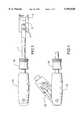
FIG. 1 is a plan view of a chisel according to the invention;
FIG. 2 is a cross-section of the chisel;
FIG. 3 is a cross-section of the spring-loaded collar;
FIG. 4 is a side view showing a storage compartment in the handle swung away from the handle;
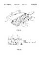
FIG. 5 is a perspective view of an alternative form of handle and a blade;
FIG. 6 is a perspective view corresponding to FIG. 5, with the blade installed;
FIG. 7 is a side view of the distal portion of the alternative handle and blade;
FIG. 8 is a side cross-sectional view corresponding to FIG. 7, showing removal of the blade;
FIG. 9 is a side view of a scraper according to the invention;
FIG. 10 is a plan view of the scraper;
FIG. 11 is a side view of a second version of a scraper;
FIG. 12 is a plan view of the second scraper;
FIG. 13 is an end view of the second scraper;
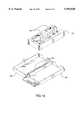
FIG. 14 is a perspective view of a "gift case" in combination with a chisel handle and replacement blades;
FIG. 15 is a plan view of the gift case insert which supports the chisel handle and replacement blades;
FIG. 16 is an exploded perspective view of the gift case;
FIG. 17 is a cross-section of the insert along the line of the recesses for the replacement blades; and
FIG. 18 is a cross-section of the insert along the line of the chisel handle.
Referring to the drawings, the chisel, for example, has a shaft 1 having adistal end 2 which is adapted to receive replacement blades or any one of a variety of different-width chisel blades 3. The blades are secured by any suitable means, such as machine screws 4, the holes for the screws being suitably threaded, or as in FIGS. 5-8, via athumbscrew 5 which bears against the upper surface of the blade. The machine screws 4 may be directed from near the distal end of the shaft into the replacement blade, as shown in FIG. 1, or vice-versa as shown in FIG. 2.
For convenience, the blades will be collectively referred to as "replacement" blades throughout this specification and in the claims, regardless of whether the blades are of the same or different sizes.
Preferably, but not necessarily, the distal end has a male or female dovetail portion 6, onto or into which a corresponding female or male dovetail portion 7 of the replacement blade may be fitted. Preferably, the distal end has a shoulder portion 8 against which the replacement blade abuts, such that the forces generated when the tool is used are transmitted directly to the shaft, to avoid generating shear forces on the machine screws.
The distal end of the handle may have anangled surface 9, configured to align with theangled surface 10 of the replacement blade, at for example a standard angle such as 24-26 degrees, or at any other desired angle. For example, an 18 degree angle could be employed for lighter duty applications. The angle of the blade does not necessarily have to match the angle of the distal end of the holder.
Storage space for extra blades, i.e. blades of different width, may be provided in thehandle 15 which is secured to the shaft. Preferably this is accomplished by virtue of a spring-loadedcollar 16 which overlieslower portions 17 of elongatedrotatable cover pieces 18, preventing rotation. The cover pieces pivot about aspringmounted pin 19, and have recesses 20 therein to provide storage space. When the spring-loaded collar is retracted, the cover pieces can be rotated, to reveal storage areas on either side of the handle.
As seen best in FIGS. 2 and 3, thecollar 16 is mounted via aspring 21 between apin 22 passing through the shaft 1 and apin 23 or the like secured inside the collar.
FIGS. 9 and 10 show the identical principle being applied to a first version of a scraper, with replacement scraper blades assemblies, comprising amount 24 and ablade 25. The details of the shaft are essentially identical to the chisel, such that the same handle and shaft could conceivably be used for either chisel or scraper blades. Therecesses 20 could be reshaped if desired, or a "universal" recess shape could be used to accommodate either chisel or scraper blades. The same shaft could be used in either case, however.
FIGS. 11-13 show a different version of scraper, with a different form ofshaft 31, simply having a broaddistal end 32 onto whichreplaceable scraper blades 25 may be mounted.
Clearly, the same principle can be applied to a wide variety of tools, and the principle is not intended to be limited to the specific tools described above and shown in the accompanying drawings. For example, the same principle obviously could be readily adapted to putty knives or other similar tools.
Instead of storing the replacement blades in the handle, it may be preferable to provide a so-called "gift case" 40, having a panel insert 42 withrecesses 44 therein to receive thereplacement blades 3. The gift case has atypical base portion 46, with a preferablytransparent lid 48 mounted thereto viahinges 50 or otherwise and securable by any suitable means, such as a conventional clasp. The handle cannot be removed from the case when the case is closed, because a blade is installed on the handle, and its width is greater than the diameter of the hole through which the handle projects.
The chisel or scraper handle is positioned preferably but not necessarily in the middle of the gift case, with for example three blade recesses 44 on each side. Any combination of blade sizes may be provided, and if desired, the blade angles may be mixed. For example, there could be three blades on one side with a standard 24-26 degree angle, and three blades on the other side with a shallower 18 degree angle, for lighter jobs. This provides the invention with the advantage of enabling a worker to use one tool for both roughing work and finishing work, i.e. by starting with a standard blade and then switching to a shallower angle blade, without having to carry around a number of different chisels.
The gift case can obviously can be configured very similarly, if not identically, for a scraper instead of a chisel, or for a combined scraper and chisel.
Claims (12)
1. A hand tool, comprising an elongated handle and a shaft extending axially from one end of said handle, a distal end of said shaft remote from said handle being specifically configured to receive a complementarily-shaped replacement blade, and means for securing said replacement blade at said distal end of said shaft, said elongated handle having a storage area defined therein, configured to receive a plurality of replacement blades, where said storage area is provided by virtue of said handle having a cover portion which is pivotable in one plane between an open position where said storage area is exposed and a closed position where said storage area is covered, said hand tool further comprising a collar positioned around said shaft to overlie a portion of said cover portion to prevent pivoting thereof towards said open position, said collar being retractable to a position where said cover portion may be pivoted.
2. A hand tool as recited in claim 1, where said distal end of said shaft has a transverse shoulder portion positioned to be abutted by a portion of said replacement blade.
3. A hand tool as recited in claim 1, where said distal end of said shaft is provided with a male or female dovetail portion configured to mate with a corresponding female or male dovetail portion provided on said replacement blade.
4. A hand tool as recited in claim 1, where said hand tool is a chisel.
5. A hand tool as recited in claim 1, where said hand tool is a scraper.
6. A hand tool as recited in claim 3, in combination with a case, said case comprising a base portion, a panel positioned across said base portion, and a lid hinged to said base portion, said panel having a plurality of recesses therein to receive replacement blades, and a recess to accommodate at least a portion of said hand tool.
7. A hand tool as recited in claim 1, wherein said collar is spring-biased to overlie said portion of said cover portion, such that said collar is retractable against said spring bias to said position where said cover portion may be pivoted.
8. A hand tool as recited in claim 7, in combination with a case, said case comprising a base portion, a panel positioned across said base portion, and a lid hinged to said base portion, said panel having a plurality of recesses therein to receive replacement blades, and a recess to accommodate at least a portion of said hand tool.
9. The combination as recited in claim 8, where said hand tool is a chisel.
10. The combination as recited in claim 8, where said hand tool is a scraper.
11. A hand tool as recited in claim 7, where said hand tool is a chisel.
12. A hand tool as recited in claim 7, where said hand tool is a scraper.
Priority Applications (1)
| Application Number | Priority Date | Filing Date | Title |
|---|---|---|---|
| US08/907,499US5953820A (en) | 1996-11-12 | 1997-08-08 | Chisels and scrapers with replaceable blades |
Applications Claiming Priority (2)
| Application Number | Priority Date | Filing Date | Title |
|---|---|---|---|
| US3125396P | 1996-11-12 | 1996-11-12 | |
| US08/907,499US5953820A (en) | 1996-11-12 | 1997-08-08 | Chisels and scrapers with replaceable blades |
Publications (1)
| Publication Number | Publication Date |
|---|---|
| US5953820Atrue US5953820A (en) | 1999-09-21 |
Family
ID=21858423
Family Applications (1)
| Application Number | Title | Priority Date | Filing Date |
|---|---|---|---|
| US08/907,499Expired - Fee RelatedUS5953820A (en) | 1996-11-12 | 1997-08-08 | Chisels and scrapers with replaceable blades |
Country Status (2)
| Country | Link |
|---|---|
| US (1) | US5953820A (en) |
| CA (1) | CA2220390A1 (en) |
Cited By (53)
| Publication number | Priority date | Publication date | Assignee | Title |
|---|---|---|---|---|
| WO2002000398A1 (en)* | 2000-06-27 | 2002-01-03 | Record Tools Limited | Hand tool and bit |
| US6568087B1 (en) | 2001-12-13 | 2003-05-27 | Donald Gringer | Scraper with stowable file |
| US20040016330A1 (en)* | 2001-07-23 | 2004-01-29 | Mccarty H. Downman | Anti-spalling combination on an impact tool with an improved holding system |
| US20050087465A1 (en)* | 2003-10-28 | 2005-04-28 | Chang Shu C. | Display pack for tool assemblies |
| US20050150340A1 (en)* | 2004-01-08 | 2005-07-14 | Graham Packaging Company, L.P. | Blade having a depression for trimming/cutting articles |
| US20050247587A1 (en)* | 2002-08-17 | 2005-11-10 | Felo Werkzeugfabrik-Holland-Letz Gmbh | Packaging for tool sets |
| DE102006005912A1 (en)* | 2006-02-09 | 2007-08-16 | Kleindienst, Otmar | Two part device for manual operation of material, has insert, hardened or molded, for certain various processing steps or materials so that this loses its connection with metal holder neither by vertical, horizontal nor inclined forces |
| US20070271796A1 (en)* | 2006-02-16 | 2007-11-29 | Oikarinen George L | Scraper having weighted cutting head for removing nail heads and other debris from surfaces |
| US20080189957A1 (en)* | 2007-02-12 | 2008-08-14 | The Stanley Works | Bi-metal chisel blade |
| US20090223064A1 (en)* | 2008-03-07 | 2009-09-10 | Venderley David J | Tool with exchangeable piece |
| US20090235535A1 (en)* | 2008-03-24 | 2009-09-24 | Helen Of Troy Limited, A Barbados Company | Scraper |
| US20090255134A1 (en)* | 2008-04-11 | 2009-10-15 | Fci Americas Technology, Inc. | Cutting blade holder |
| USD615262S1 (en) | 2009-02-24 | 2010-05-04 | American Safety Razor | Scraper |
| USD615261S1 (en) | 2009-02-12 | 2010-05-04 | American Safety Razor | Scraper |
| US20100139101A1 (en)* | 2006-06-30 | 2010-06-10 | Robert Cooper | Chisels |
| GB2472154A (en)* | 2010-09-13 | 2011-01-26 | Simon Hackett | Chisel with removable blade element |
| USD631715S1 (en)* | 2009-05-09 | 2011-02-01 | Tobias M N F Cardew | Beveled chisel tip |
| USD632151S1 (en)* | 2009-05-09 | 2011-02-08 | Tobias M N F Cardew | Channeled chisel tip |
| USD637053S1 (en)* | 2009-05-09 | 2011-05-03 | Tobias M N F Cardew | Chisel tip |
| CN102699933A (en)* | 2012-06-14 | 2012-10-03 | 青岛智多星工贸有限公司 | Multifunctional cutting tool |
| USD672626S1 (en)* | 2010-06-25 | 2012-12-18 | Samvaz Sa | Support for cutting tool |
| KR101214670B1 (en) | 2011-07-07 | 2012-12-21 | 임진석 | A scraper |
| US20130030532A1 (en)* | 2008-06-06 | 2013-01-31 | Providence Medical Technology, Inc. | Vertebral joint implants and delivery tools |
| US8726782B2 (en) | 2002-03-05 | 2014-05-20 | Defenshield, Inc. | Bullet resistant barrier |
| US8826544B1 (en)* | 2011-02-14 | 2014-09-09 | John David Savage, Jr. | Sealant removal tool |
| US8834530B2 (en) | 2006-12-29 | 2014-09-16 | Providence Medical Technology, Inc. | Cervical distraction method |
| US8973273B2 (en) | 2012-01-13 | 2015-03-10 | Stanley Black & Decker, Inc. | Foldable chisel |
| US9005288B2 (en) | 2008-01-09 | 2015-04-14 | Providence Medical Techonlogy, Inc. | Methods and apparatus for accessing and treating the facet joint |
| USD732667S1 (en) | 2012-10-23 | 2015-06-23 | Providence Medical Technology, Inc. | Cage spinal implant |
| USD745156S1 (en) | 2012-10-23 | 2015-12-08 | Providence Medical Technology, Inc. | Spinal implant |
| US9333086B2 (en) | 2008-06-06 | 2016-05-10 | Providence Medical Technology, Inc. | Spinal facet cage implant |
| US9381049B2 (en) | 2008-06-06 | 2016-07-05 | Providence Medical Technology, Inc. | Composite spinal facet implant with textured surfaces |
| US10149673B2 (en) | 2008-06-06 | 2018-12-11 | Providence Medical Technology, Inc. | Facet joint implants and delivery tools |
| US10201375B2 (en) | 2014-05-28 | 2019-02-12 | Providence Medical Technology, Inc. | Lateral mass fixation system |
| USD841165S1 (en) | 2015-10-13 | 2019-02-19 | Providence Medical Technology, Inc. | Cervical cage |
| US10238501B2 (en) | 2008-06-06 | 2019-03-26 | Providence Medical Technology, Inc. | Cervical distraction/implant delivery device |
| US10383449B2 (en) | 2017-05-12 | 2019-08-20 | Defenshield, Inc. | Barrier bench |
| US10466016B2 (en) | 2017-06-01 | 2019-11-05 | Defenshield, Inc. | Ballistic shield |
| USD887552S1 (en) | 2016-07-01 | 2020-06-16 | Providence Medical Technology, Inc. | Cervical cage |
| US10682243B2 (en) | 2015-10-13 | 2020-06-16 | Providence Medical Technology, Inc. | Spinal joint implant delivery device and system |
| USD898914S1 (en) | 2018-12-05 | 2020-10-13 | Medline Industries, Inc. | Bone preparation tool |
| USD911525S1 (en) | 2019-06-21 | 2021-02-23 | Providence Medical Technology, Inc. | Spinal cage |
| USD916408S1 (en)* | 2018-10-09 | 2021-04-13 | Hung-Wei Lin | Scraper |
| US11065039B2 (en) | 2016-06-28 | 2021-07-20 | Providence Medical Technology, Inc. | Spinal implant and methods of using the same |
| USD933230S1 (en) | 2019-04-15 | 2021-10-12 | Providence Medical Technology, Inc. | Cervical cage |
| US11224521B2 (en) | 2008-06-06 | 2022-01-18 | Providence Medical Technology, Inc. | Cervical distraction/implant delivery device |
| USD945621S1 (en) | 2020-02-27 | 2022-03-08 | Providence Medical Technology, Inc. | Spinal cage |
| US11272964B2 (en) | 2008-06-06 | 2022-03-15 | Providence Medical Technology, Inc. | Vertebral joint implants and delivery tools |
| US11648128B2 (en) | 2018-01-04 | 2023-05-16 | Providence Medical Technology, Inc. | Facet screw and delivery device |
| US11871968B2 (en) | 2017-05-19 | 2024-01-16 | Providence Medical Technology, Inc. | Spinal fixation access and delivery system |
| US12004781B2 (en) | 2014-05-27 | 2024-06-11 | Providence Medical Technology, Inc. | Lateral mass fixation implant |
| US12144513B2 (en) | 2018-09-21 | 2024-11-19 | Providence Medical Technology, Inc. | Vertebral joint access and decortication devices and methods of using |
| USD1098431S1 (en) | 2023-02-27 | 2025-10-14 | Providence Medical Technology, Inc. | Spinal cage |
Citations (12)
| Publication number | Priority date | Publication date | Assignee | Title |
|---|---|---|---|---|
| US17128A (en)* | 1857-04-21 | Improvement in blacksmiths butterises | ||
| US108596A (en)* | 1870-10-25 | Improvement in pocket-cutlery | ||
| US143413A (en)* | 1873-10-07 | Improvement in chisels | ||
| US178627A (en)* | 1876-06-13 | Improvement in farriers buttresses | ||
| US420529A (en)* | 1890-02-04 | Chisel | ||
| US433078A (en)* | 1890-07-29 | Cutting-tool and handle | ||
| US1082802A (en)* | 1913-04-02 | 1913-12-30 | Peter Full | Scraping-tool. |
| US2131358A (en)* | 1936-02-11 | 1938-09-27 | Rothschild Sol | Scalpel |
| US3370697A (en)* | 1967-05-08 | 1968-02-27 | Oxwall Tool Co Ltd | Display package and article container |
| US3829967A (en)* | 1971-12-09 | 1974-08-20 | Stanley Tools Ltd | Folding blade pocket knives |
| US5441152A (en)* | 1994-03-29 | 1995-08-15 | Estes; Ronald L. | Organizer devices for orthopedic equipment normally found in cast removal situations |
| US5537747A (en)* | 1995-06-19 | 1996-07-23 | Industrial Tool & Die Company, Inc. | Nail clipping apparatus |
- 1997
- 1997-08-08USUS08/907,499patent/US5953820A/ennot_activeExpired - Fee Related
- 1997-11-07CACA002220390Apatent/CA2220390A1/ennot_activeAbandoned
Patent Citations (12)
| Publication number | Priority date | Publication date | Assignee | Title |
|---|---|---|---|---|
| US17128A (en)* | 1857-04-21 | Improvement in blacksmiths butterises | ||
| US108596A (en)* | 1870-10-25 | Improvement in pocket-cutlery | ||
| US143413A (en)* | 1873-10-07 | Improvement in chisels | ||
| US178627A (en)* | 1876-06-13 | Improvement in farriers buttresses | ||
| US420529A (en)* | 1890-02-04 | Chisel | ||
| US433078A (en)* | 1890-07-29 | Cutting-tool and handle | ||
| US1082802A (en)* | 1913-04-02 | 1913-12-30 | Peter Full | Scraping-tool. |
| US2131358A (en)* | 1936-02-11 | 1938-09-27 | Rothschild Sol | Scalpel |
| US3370697A (en)* | 1967-05-08 | 1968-02-27 | Oxwall Tool Co Ltd | Display package and article container |
| US3829967A (en)* | 1971-12-09 | 1974-08-20 | Stanley Tools Ltd | Folding blade pocket knives |
| US5441152A (en)* | 1994-03-29 | 1995-08-15 | Estes; Ronald L. | Organizer devices for orthopedic equipment normally found in cast removal situations |
| US5537747A (en)* | 1995-06-19 | 1996-07-23 | Industrial Tool & Die Company, Inc. | Nail clipping apparatus |
Cited By (83)
| Publication number | Priority date | Publication date | Assignee | Title |
|---|---|---|---|---|
| US20040134077A1 (en)* | 2000-06-27 | 2004-07-15 | Martin Gramham John | Hand tool and bit |
| WO2002000398A1 (en)* | 2000-06-27 | 2002-01-03 | Record Tools Limited | Hand tool and bit |
| US9089962B2 (en)* | 2001-07-23 | 2015-07-28 | Hard Cap Technologies, LLC | Anti-spalling combination on an impact tool with an improved holding system |
| US20040016330A1 (en)* | 2001-07-23 | 2004-01-29 | Mccarty H. Downman | Anti-spalling combination on an impact tool with an improved holding system |
| US6568087B1 (en) | 2001-12-13 | 2003-05-27 | Donald Gringer | Scraper with stowable file |
| US8726782B2 (en) | 2002-03-05 | 2014-05-20 | Defenshield, Inc. | Bullet resistant barrier |
| US20050247587A1 (en)* | 2002-08-17 | 2005-11-10 | Felo Werkzeugfabrik-Holland-Letz Gmbh | Packaging for tool sets |
| US20050087465A1 (en)* | 2003-10-28 | 2005-04-28 | Chang Shu C. | Display pack for tool assemblies |
| US20050150340A1 (en)* | 2004-01-08 | 2005-07-14 | Graham Packaging Company, L.P. | Blade having a depression for trimming/cutting articles |
| DE102006005912A1 (en)* | 2006-02-09 | 2007-08-16 | Kleindienst, Otmar | Two part device for manual operation of material, has insert, hardened or molded, for certain various processing steps or materials so that this loses its connection with metal holder neither by vertical, horizontal nor inclined forces |
| US20070271796A1 (en)* | 2006-02-16 | 2007-11-29 | Oikarinen George L | Scraper having weighted cutting head for removing nail heads and other debris from surfaces |
| US20100139101A1 (en)* | 2006-06-30 | 2010-06-10 | Robert Cooper | Chisels |
| US10219910B2 (en) | 2006-12-29 | 2019-03-05 | Providence Medical Technology, Inc. | Cervical distraction method |
| US9622873B2 (en) | 2006-12-29 | 2017-04-18 | Providence Medical Technology, Inc. | Cervical distraction method |
| US8834530B2 (en) | 2006-12-29 | 2014-09-16 | Providence Medical Technology, Inc. | Cervical distraction method |
| US11285010B2 (en) | 2006-12-29 | 2022-03-29 | Providence Medical Technology, Inc. | Cervical distraction method |
| US20080189957A1 (en)* | 2007-02-12 | 2008-08-14 | The Stanley Works | Bi-metal chisel blade |
| US11559408B2 (en) | 2008-01-09 | 2023-01-24 | Providence Medical Technology, Inc. | Methods and apparatus for accessing and treating the facet joint |
| US9005288B2 (en) | 2008-01-09 | 2015-04-14 | Providence Medical Techonlogy, Inc. | Methods and apparatus for accessing and treating the facet joint |
| US20090223064A1 (en)* | 2008-03-07 | 2009-09-10 | Venderley David J | Tool with exchangeable piece |
| US20090235535A1 (en)* | 2008-03-24 | 2009-09-24 | Helen Of Troy Limited, A Barbados Company | Scraper |
| US20090255134A1 (en)* | 2008-04-11 | 2009-10-15 | Fci Americas Technology, Inc. | Cutting blade holder |
| US20130030532A1 (en)* | 2008-06-06 | 2013-01-31 | Providence Medical Technology, Inc. | Vertebral joint implants and delivery tools |
| US10172721B2 (en) | 2008-06-06 | 2019-01-08 | Providence Technology, Inc. | Spinal facet cage implant |
| US11344339B2 (en) | 2008-06-06 | 2022-05-31 | Providence Medical Technology, Inc. | Vertebral joint implants and delivery tools |
| US11890038B2 (en) | 2008-06-06 | 2024-02-06 | Providence Medical Technology, Inc. | Vertebral joint implants and delivery tools |
| US8753345B2 (en) | 2008-06-06 | 2014-06-17 | Providence Medical Technology, Inc. | Vertebral joint implants and delivery tools |
| US8753347B2 (en) | 2008-06-06 | 2014-06-17 | Providence Medical Technology, Inc. | Vertebral joint implants and delivery tools |
| US8828062B2 (en) | 2008-06-06 | 2014-09-09 | Providence Medical Technology, Inc. | Vertebral joint implants and delivery tools |
| US10568666B2 (en) | 2008-06-06 | 2020-02-25 | Providence Medical Technology, Inc. | Vertebral joint implants and delivery tools |
| US10238501B2 (en) | 2008-06-06 | 2019-03-26 | Providence Medical Technology, Inc. | Cervical distraction/implant delivery device |
| US8834472B2 (en)* | 2008-06-06 | 2014-09-16 | Providence Medical Technology, Inc. | Vertebral joint implants and delivery tools |
| US11272964B2 (en) | 2008-06-06 | 2022-03-15 | Providence Medical Technology, Inc. | Vertebral joint implants and delivery tools |
| US10226285B2 (en) | 2008-06-06 | 2019-03-12 | Providence Medical Technology, Inc. | Vertebral joint implants and delivery tools |
| US11224521B2 (en) | 2008-06-06 | 2022-01-18 | Providence Medical Technology, Inc. | Cervical distraction/implant delivery device |
| US12409044B2 (en) | 2008-06-06 | 2025-09-09 | Providence Medical Technology, Inc. | Cervical distraction/implant delivery device |
| US11141144B2 (en) | 2008-06-06 | 2021-10-12 | Providence Medical Technology, Inc. | Facet joint implants and delivery tools |
| US9333086B2 (en) | 2008-06-06 | 2016-05-10 | Providence Medical Technology, Inc. | Spinal facet cage implant |
| US9381049B2 (en) | 2008-06-06 | 2016-07-05 | Providence Medical Technology, Inc. | Composite spinal facet implant with textured surfaces |
| US10588672B2 (en) | 2008-06-06 | 2020-03-17 | Providence Medical Technology, Inc. | Vertebral joint implants and delivery tools |
| US9622791B2 (en) | 2008-06-06 | 2017-04-18 | Providence Medical Technology, Inc. | Vertebral joint implants and delivery tools |
| US9629665B2 (en) | 2008-06-06 | 2017-04-25 | Providence Medical Technology, Inc. | Vertebral joint implants and delivery tools |
| US10039649B2 (en) | 2008-06-06 | 2018-08-07 | Providence Medical Technology, Inc. | Composite spinal facet implant with textured surfaces |
| US10149673B2 (en) | 2008-06-06 | 2018-12-11 | Providence Medical Technology, Inc. | Facet joint implants and delivery tools |
| US10456175B2 (en) | 2008-06-06 | 2019-10-29 | Providence Medical Technology, Inc. | Vertebral joint implants and delivery tools |
| US11058553B2 (en) | 2008-06-06 | 2021-07-13 | Providence Medical Technology, Inc. | Spinal facet cage implant |
| USD615261S1 (en) | 2009-02-12 | 2010-05-04 | American Safety Razor | Scraper |
| USD615262S1 (en) | 2009-02-24 | 2010-05-04 | American Safety Razor | Scraper |
| USD631715S1 (en)* | 2009-05-09 | 2011-02-01 | Tobias M N F Cardew | Beveled chisel tip |
| USD632151S1 (en)* | 2009-05-09 | 2011-02-08 | Tobias M N F Cardew | Channeled chisel tip |
| USD637053S1 (en)* | 2009-05-09 | 2011-05-03 | Tobias M N F Cardew | Chisel tip |
| USD672626S1 (en)* | 2010-06-25 | 2012-12-18 | Samvaz Sa | Support for cutting tool |
| USD679157S1 (en)* | 2010-06-25 | 2013-04-02 | Samvaz Sa | Cutting tool |
| GB2472154A (en)* | 2010-09-13 | 2011-01-26 | Simon Hackett | Chisel with removable blade element |
| US8826544B1 (en)* | 2011-02-14 | 2014-09-09 | John David Savage, Jr. | Sealant removal tool |
| KR101214670B1 (en) | 2011-07-07 | 2012-12-21 | 임진석 | A scraper |
| US8973273B2 (en) | 2012-01-13 | 2015-03-10 | Stanley Black & Decker, Inc. | Foldable chisel |
| CN102699933A (en)* | 2012-06-14 | 2012-10-03 | 青岛智多星工贸有限公司 | Multifunctional cutting tool |
| USD732667S1 (en) | 2012-10-23 | 2015-06-23 | Providence Medical Technology, Inc. | Cage spinal implant |
| USD745156S1 (en) | 2012-10-23 | 2015-12-08 | Providence Medical Technology, Inc. | Spinal implant |
| USRE48501E1 (en) | 2012-10-23 | 2021-04-06 | Providence Medical Technology, Inc. | Cage spinal implant |
| US12004781B2 (en) | 2014-05-27 | 2024-06-11 | Providence Medical Technology, Inc. | Lateral mass fixation implant |
| US10201375B2 (en) | 2014-05-28 | 2019-02-12 | Providence Medical Technology, Inc. | Lateral mass fixation system |
| US11058466B2 (en) | 2014-05-28 | 2021-07-13 | Providence Medical Technology, Inc. | Lateral mass fixation system |
| US10682243B2 (en) | 2015-10-13 | 2020-06-16 | Providence Medical Technology, Inc. | Spinal joint implant delivery device and system |
| USD884895S1 (en) | 2015-10-13 | 2020-05-19 | Providence Medical Technology, Inc. | Cervical cage |
| USD841165S1 (en) | 2015-10-13 | 2019-02-19 | Providence Medical Technology, Inc. | Cervical cage |
| US11065039B2 (en) | 2016-06-28 | 2021-07-20 | Providence Medical Technology, Inc. | Spinal implant and methods of using the same |
| USD887552S1 (en) | 2016-07-01 | 2020-06-16 | Providence Medical Technology, Inc. | Cervical cage |
| US10383449B2 (en) | 2017-05-12 | 2019-08-20 | Defenshield, Inc. | Barrier bench |
| US11871968B2 (en) | 2017-05-19 | 2024-01-16 | Providence Medical Technology, Inc. | Spinal fixation access and delivery system |
| US10466016B2 (en) | 2017-06-01 | 2019-11-05 | Defenshield, Inc. | Ballistic shield |
| US11648128B2 (en) | 2018-01-04 | 2023-05-16 | Providence Medical Technology, Inc. | Facet screw and delivery device |
| US11813172B2 (en) | 2018-01-04 | 2023-11-14 | Providence Medical Technology, Inc. | Facet screw and delivery device |
| US12144513B2 (en) | 2018-09-21 | 2024-11-19 | Providence Medical Technology, Inc. | Vertebral joint access and decortication devices and methods of using |
| USD916408S1 (en)* | 2018-10-09 | 2021-04-13 | Hung-Wei Lin | Scraper |
| USD1005487S1 (en) | 2018-12-05 | 2023-11-21 | Medline Industries, Lp | Bone preparation tool |
| USD898914S1 (en) | 2018-12-05 | 2020-10-13 | Medline Industries, Inc. | Bone preparation tool |
| USD933230S1 (en) | 2019-04-15 | 2021-10-12 | Providence Medical Technology, Inc. | Cervical cage |
| USD911525S1 (en) | 2019-06-21 | 2021-02-23 | Providence Medical Technology, Inc. | Spinal cage |
| USD945621S1 (en) | 2020-02-27 | 2022-03-08 | Providence Medical Technology, Inc. | Spinal cage |
| USD1098431S1 (en) | 2023-02-27 | 2025-10-14 | Providence Medical Technology, Inc. | Spinal cage |
| USD1098433S1 (en) | 2023-12-28 | 2025-10-14 | Providence Medical Technology, Inc. | Spinal cage |
Also Published As
| Publication number | Publication date |
|---|---|
| CA2220390A1 (en) | 1998-05-12 |
Similar Documents
| Publication | Publication Date | Title |
|---|---|---|
| US5953820A (en) | Chisels and scrapers with replaceable blades | |
| US5692304A (en) | Locking device for folding tool | |
| US4109380A (en) | Cutting tool and blade holder for replaceable blades | |
| US5251352A (en) | Seven way combination tool | |
| US5553340A (en) | Utility tool for power chain saw | |
| US6145144A (en) | Pocket tool with interchangeable components | |
| US7565747B2 (en) | Double-edged utility knife | |
| US6321454B1 (en) | Utility knife | |
| US20080276470A1 (en) | Reciprocating Saw and Attachments | |
| US5673487A (en) | Cutting pliers for plastic material sections, rubber-like joints and similar | |
| US6745478B2 (en) | Multi-purpose work knife | |
| CA2341299A1 (en) | Drill tool assembly | |
| CA2298505A1 (en) | Toolboxes and tool cases with pivotable component holder | |
| US5054201A (en) | Double insert deburring tool | |
| US5027512A (en) | Manual cutter insert tool | |
| US5347718A (en) | Folding handle hatchet | |
| US5641066A (en) | Rotary tool bit storage case | |
| US5320458A (en) | Cutting tool having a cutter cartridge adjustable around two adjustment axes | |
| US6592236B1 (en) | Foldable emergency hammer | |
| EP3434433B1 (en) | Cutting tool holding device | |
| US6021771A (en) | Surfacing machine with "strip-sert" cutter assemblies | |
| CA2048873A1 (en) | Multiple purpose sharpening tool | |
| WO2005099975A2 (en) | Utility knife for glaziers | |
| US6079301A (en) | Multi-wrench tool kit | |
| CA2150178A1 (en) | Rotary cutters |
Legal Events
| Date | Code | Title | Description |
|---|---|---|---|
| AS | Assignment | Owner name:MAXTECH, INC., MICHIGAN Free format text:ASSIGNMENT OF ASSIGNORS INTEREST;ASSIGNOR:VASUDEVA, KAILASH C.;REEL/FRAME:008748/0626 Effective date:19970806 | |
| REMI | Maintenance fee reminder mailed | ||
| LAPS | Lapse for failure to pay maintenance fees | ||
| STCH | Information on status: patent discontinuation | Free format text:PATENT EXPIRED DUE TO NONPAYMENT OF MAINTENANCE FEES UNDER 37 CFR 1.362 | |
| FP | Lapsed due to failure to pay maintenance fee | Effective date:20030921 |