US5953001A - Computer input stylus and texture control system - Google Patents
Computer input stylus and texture control systemDownload PDFInfo
- Publication number
- US5953001A US5953001AUS08/997,026US99702697AUS5953001AUS 5953001 AUS5953001 AUS 5953001AUS 99702697 AUS99702697 AUS 99702697AUS 5953001 AUS5953001 AUS 5953001A
- Authority
- US
- United States
- Prior art keywords
- computer
- color
- stylus
- cylindrical body
- input stylus
- Prior art date
- Legal status (The legal status is an assumption and is not a legal conclusion. Google has not performed a legal analysis and makes no representation as to the accuracy of the status listed.)
- Expired - Fee Related
Links
Images


Classifications
- G—PHYSICS
- G06—COMPUTING OR CALCULATING; COUNTING
- G06F—ELECTRIC DIGITAL DATA PROCESSING
- G06F3/00—Input arrangements for transferring data to be processed into a form capable of being handled by the computer; Output arrangements for transferring data from processing unit to output unit, e.g. interface arrangements
- G06F3/01—Input arrangements or combined input and output arrangements for interaction between user and computer
- G06F3/03—Arrangements for converting the position or the displacement of a member into a coded form
- G06F3/033—Pointing devices displaced or positioned by the user, e.g. mice, trackballs, pens or joysticks; Accessories therefor
- G06F3/0354—Pointing devices displaced or positioned by the user, e.g. mice, trackballs, pens or joysticks; Accessories therefor with detection of 2D relative movements between the device, or an operating part thereof, and a plane or surface, e.g. 2D mice, trackballs, pens or pucks
- G06F3/03545—Pens or stylus
- G—PHYSICS
- G06—COMPUTING OR CALCULATING; COUNTING
- G06T—IMAGE DATA PROCESSING OR GENERATION, IN GENERAL
- G06T11/00—2D [Two Dimensional] image generation
- G06T11/001—Texturing; Colouring; Generation of texture or colour
Definitions
- the present inventionrelates in general to an improved computer system and in particular to improvements in computer-implemented drawing applications. Still more particularly, the present invention relates to a system for providing input stylus texture control in a computer-implemented drawing application.
- Computer-implemented drawing programscommonly utilize a so-called "graphical pointing device” to designate locations within a computer display for "painting" a portion of an artistic composition.
- graphical pointing deviceis the "mouse.”
- a usermay graphically select commands or options and/or designate locations within the computer display for application of such commands and options.
- Another common computer input device for utilization with computer-implemented drawing applicationsis the light pen or stylus.
- Such a deviceis typically utilized in conjunction with an input pad or the surface of the computer display to enter graphic elements into a computer-created drawing.
- a color or patternis selected from a palette or menu within the drawing application utilizing key strokes or mouse clicks, and that color or pattern is then applied to locations within the computer display utilizing the light pen or stylus.
- a computer-input styluswhich provides texture control when utilized in conjunction with a computer-implemented software-based drawing application.
- the input stylusincludes a cylindrical body and a conical tip.
- a color display within the stylusis utilized to illuminate the conical tip with a color indicative of a currently selected color within the software-based drawing application, providing visual color feedback.
- Texture selectionis accomplished utilizing a texture selection input actuator mounted to the cylindrical body of the input stylus.
- the texture selection input actuatorsuch as a trackpoint device, is utilized to vary the texture of a selected color or pattern.
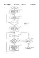
- FIG. 1is a pictorial view of a computer system which may be utilized to implement the computer input stylus of the present invention
- FIG. 2is a high-level block diagram of the computer system of FIG. 1;
- FIG. 3is a partially cutaway pictorial version of the computer-input stylus of the present invention.
- FIGS. 4A-4Dare pictorial representations of varied textures/patterns which may be created utilizing the computer input stylus of the present invention.
- FIG. 5is a high-level logic flowchart illustrating a process for controlling the selection of texture utilizing the computer-input stylus of the present invention.
- data processing system 20includes processor 22, keyboard 82 and display 96. Keyboard 82 is coupled to processor 22 by cable 28.
- Display 96includes a display screen 30, which may be implemented utilizing a cathode ray tube (CRT), a liquid crystal display (LCD), an electrode luminescent panel or other similar display device.
- the data processing system 20also may include a pointing device which may be implemented utilizing a trackball, joystick, touch-sensitive tablet or screen, track path or, as illustrated, a mouse.
- Processor 22also may be coupled to one or more peripheral devices such as a modem, CD-ROM or network adapter (not shown) or a floppy disk drive 40, which may be internal or external to the enclosure of processor 22.
- peripheral devicessuch as a modem, CD-ROM or network adapter (not shown) or a floppy disk drive 40, which may be internal or external to the enclosure of processor 22.
- An output devicesuch as printer 100 also may be coupled to processor 22.
- a computer-input stylus 92also is coupled to processor 22.
- Computer-input stylus 92may be utilized, in a manner which will be set forth in greater detail herein, to draw or "paint" an artistic composition on display screen 30 within display 96. It also should be noted and recognized by those persons of ordinary skill in the art that display 96 and keyboard 82 may be implemented utilizing any one of several known standard available components.
- data processing system 20is preferably controlled primarily by computer-readable instructions, which may be in the form of software, wherever or by whatever means such software is stored or accessed.
- Such softwaremay be executed within central processing unit (CPU) 50 to cause data processing system 20 to do work.
- CPUcentral processing unit
- a computer-implemented software drawing applicationmay be stored within memory within data processing system 20 and executed within central processing unit (CPU) 50 to assist in the creation of an artistic composition within data processing system 20.
- Memory devices coupled to system bus 5include random-access memory (RAM) 56, read-only memory (ROM) 58 and non-volatile memory 60.
- RAMrandom-access memory
- ROMread-only memory
- non-volatile memory 60Such memories include circuitry that allows information to be stored and retrieved. Read-only memory contains data which cannot be modified. Data stored within random-access memory can be changed by CPU 50 or other hardware devices.
- Non-volatile memoryis memory that does not lose data when power is removed.
- Non-volatile memoriesinclude ROM, E-PROM, flash memory or battery-pack CMOS RAM. As shown in FIG. 2, such battery-pack CMOS RAM may be used to store configuration information.
- An expansion card or boardis a circuit board which includes chips or other electronic components which, when connected to a data processing system, add functions or resources to that system.
- expansion cardsmay add memory, disk-drive controllers 66, video support, parallel and serial ports and internal modems.
- expansion cardsusually take the form of PC cards, which are credit-card-sized devices designed to plug into a slot in the side or back of a computer.
- PCMCIA slotPersonal Computer Memory Card International Association
- empty slots 68 depicted within FIG. 2may be utilized to receive various types of expansion cards or PCMCIA cards.
- Disk controller 66 and diskette controller 70both include special purpose integrated circuits and associated circuitry which direct and control reading from and writing to hard disk drive 72 and floppy disk or diskette 74, respectively. Such disk controllers handle tasks such as positioning read/write heads, mediating between the drive and CPU 50, and controlling the transfer of information to and from memory. A single disk controller may be able to control more than one disk drive.
- CD-ROM controller 76may be included in data processing system 20 for reading data from CD-ROM 78 (compact disk read-only memory). Such CD-ROMs use laser optics rather than magnetic means for reading data.
- Keyboard/mouse controller 80is provided in data processing system 20 for interfacing with keyboard 82 and communications link 84.
- Communications link 84may be coupled to a pointing device which may be used to control an on-screen element such as a graphical pointer or curser, which may take the form of an arrow having a hotspot that specifies the location of the pointer when the user presses a mouse button.
- a pointing devicewhich may be used to control an on-screen element such as a graphical pointer or curser, which may take the form of an arrow having a hotspot that specifies the location of the pointer when the user presses a mouse button.
- Other pointing devicesincluding graphics tablets, joysticks, trackballs, trackpads and the pointing device sold under the trademark "Track Point" by International Business Machines Corporation also may be utilized.
- data processing system 20may communicate with stylus 92 utilizing stylus controller 88.
- Stylus controller 88is typically attached to system bus 5 in the form of a serial port.
- communications link 91 between stylus 92 and stylus controller 88may take the form of a wire cable, an infrared link or a radio-frequency link, utilizing communication techniques which are well-known to those having ordinary skill in the art.
- stylus controller 88transmits information between CPU 50 and stylus 92 one bit at a time over a single line.
- Serial communicationmay be synchronous (controlled by some standard such as a clock) or asynchronous (managed by the exchange of control signals that govern the flow of information). Examples of serial communication standards include RS-232 interface and the RS-422 interface. As illustrated, stylus controller 88 then may be utilized to communicate with stylus 92.
- stylus 92also may communicate with data processing system 20 via a parallel port if such communication is desired.
- the equivalence of communication between a peripheral device and a processing system via serial or parallel portsis well-known to those having ordinary skill in the art.
- stylus 92includes a texture selection input actuator, such as a trackpoint device, which is preferably coupled to keyboard mouse controller 80 via communications link 84, to control texture selection in a manner which will be explained in greater detail herein.
- a texture selection input actuatorsuch as a trackpoint device
- Network adapter 90also may be utilized to connect data processing system to a local area network.
- Local area networksmay provide computer users with a means for communicating and transferring software and information electronically. Additionally, such network may provide distributed processing, which involves several computers in the sharing of workloads or cooperative efforts in performing a task.
- Display 96which is controlled by display controller 98, is utilized to display visual output generated by data processing system 20. Such visual output may include text, graphics, animated graphics and video.
- Display 96may be implemented with a cathode-ray-tube-based video display, a liquid-crystal-based flat panel display or a gas-plasma-based flat panel display.
- Display controller 98preferably includes electronic components which are required to generate video signals which are sent to display 96 and which are necessary to detect the presence of the tip of stylus 92 at various locations on display screen 30.
- Printer 100also is depicted as coupled to data processing system 20 via parallel controller 102.
- Printer 100may be utilized to put text or other computer-generated images, or combinations thereof, on paper or on another medium such as a transparency sheet.
- Other types of printersmay include an image setter, a plotter or a film recorder.
- Parallel controller 102may be utilized to send multiple data and control bits simultaneously over a plurality of wires connected between system bus 5 and another parallel communication device, such as printer 100, or stylus 92.
- CPU 50fetches, decodes and executes instructions and transfers information to and from other resources via the computer's main data-transfer path system bus 5.
- a busconnects the components in a data processing system 20 and defines the medium for data exchange.
- System bus 5connects together and allows for the exchange of data between memory units 56, 58 and 60; CPU 50; and other devices depicted within FIG. 2.
- a data processing system constructed in accordance with the present inventionmay have multiple components selected from the foregoing, including multiple processors.
- FIG. 3there is depicted a partially cutaway pictorial view of computer input stylus 92 of the present invention.
- computer-input stylus 92may be connected to data processing system 20 via communications link 91 which may be implemented utilizing a wire, infrared or radio frequency link to data processing system 20, and computer-input stylus 92 may be connected to keyboard mouse controller 80 via communications link 84.
- computer-input stylus 92includes a cylindrical body 110 and a conical stylus tip 124. Depicted in the cutaway portion of cylindrical body 110 is a printed circuit board 112 which serves to mount various electronic components including communications circuit 114 and color driver circuit 116. Also mounted to printed circuit board 112 are multiple light-emitting diodes. Specifically, red light-emitting diode 118, green light-emitting diode 120 and blue light-emitting diode 122.
- control signals indicative of that color valueare transferred from data processing system 20 to computer-input stylus 92 via communications link 91. Those signals are received by communications circuit 114 and translated into control signals for use by color driver 116.
- pulses of varying widthsmay be applied to each light-emitting diode in turn, and in a manner well-known to those having skill in the color-graphics art, by combining various-level outputs from each of the three primary-color light-emitting diodes, it will be possible to create a resultant color which is identical to the color selected within the computer-based palette of the computer-implemented software-based drawing application.
- a bundle of fiber-optic cables 126is mounted within conical stylus tip 124.
- One end of the bundle of fiber-optic cables 126extends from the tip of conical stylus tip 124 and serves as the output point for computer-input stylus 92.
- the remaining ends of the bundle of fiber-optic cables 126are mounted in the vicinity of light-emitting diodes 118, 120 and 122 and receive, from those diodes, radiation which, when combined, results in the production of a selected color which matches the color selected within the computer-implemented software drawing application.
- conical stylus tip 124is preferably provided having a mirrored inner surface so that light emitted by light-emitting diodes 118, 120 and 122 will be primarily absorbed by the bundle of fiber-optic cables 126 and output at the extended tip thereof.
- the tip of computer-input stylus 92will be illuminated with a color which is identical to the color selected from the computer-based palette within the drawing application.
- the artist utilizing computer-input stylus 92can perceive the color which is about to be applied by viewing the tip of the stylus in a manner analogous to viewing the tip of a paintbrush which has been dipped into a selected paint color.
- texture selection input actuator 128is a device which converts force to motion of a pointing element, such as the trackpoint device manufactured by International Business Machines Corporation of Armonk, N.Y. In this manner, as will be explained in greater detail below, texture selection input actuator 128 may be utilized to select and/or vary a texture or a pattern from among the textures or patterns available within a computer-provided color palette.
- FIGS. 4A-4Cthere are depicted pictorial representations of varied textures/patterns which may be created utilizing the computer-input stylus of the present invention.
- FIG. 4Adepicts a simulated wood-grain pattern.
- Such patternsare commonly available in computer-implemented drawing programs and may be selected by a user utilizing a menu or other well-known user-interface devices.
- texture selection input actuator 128may be utilized by the user to dynamically and continuously vary the spacing between pattern elements.
- FIG. 4Cthe simulated woodgrain pattern of FIGS. 4A and 4B also is present, with a pattern-spacing element which has been further modified to place the elements of the pattern closer together.
- texture selection input actuator 28it is possible to dynamically and continuously vary the spacing between pattern elements from the pattern depicted in FIG. 4A to the pattern depicted in FIG. 4C, as illustrated in FIG. 4D, greatly enhancing the natural appearance of the simulated wood-grain in a manner which will be appreciated by those having skill in the artistic arts.
- computer-input stylus 92may be utilized in the manner of a paintbrush or the like and applied to dynamically vary the appearance of a color or pattern within a given section of a drawing created utilizing a computer-implemented drawing program.
- FIG. 5there is depicted a high-level logic flowchart which illustrates a process for controlling the computer-input stylus of the present invention. As depicted, this process begins at block 140, thereafter passing to block 142. Block 142 illustrates the initiation of the software-based drawing program and the loading of stylus drivers. Those having ordinary skill in the art will appreciate that such stylus drivers will be drivers which will generate the necessary control signals to create a color illumination within the tip of computer-input stylus 92 which corresponds to the color selected within the drawing program. Next, the process passes to block 144.
- Block 144illustrates the calibration of the stylus colors. This may be accomplished, as discussed above, by comparing the tip of computer-input stylus 92 to a display within the display screen 30 of data processing system 20 and varying the output to achieve a match. The currents applied to each of the light-emitting diodes may be carefully adjusted to achieve calibration which overcomes any process irregularities. In a preferred embodiment of the present invention, such calibration data may be stored within computer memory, and calibration will not be required on a frequent basis. Additionally, computer-input stylus 92 may be implemented utilizing the ICM (Image Color Matching) protocols in Windows 95, a trademark of the Microsoft Corporation of Redmond, Wash.
- ICMImage Color Matching
- Block 148illustrates the selection of a color by the user from the computer-based color palette utilized with the drawing program selected for implementation. Thereafter, the process passes to block 150.
- Block 150illustrates the illumination of the stylus tip in a manner set forth above with respect to FIGS. 3 and 4. Thereafter, the process passes to block 152.
- Block 152illustrates a determination of whether or not trackpoint movement indicating new texture parameters have been selected is detected. If new texture parameters have not been selected, the process passes to block 154.
- Block 154illustrates a determination of whether or not the application has terminated and, if not, the process returns in an iterative fashion to block 150 and continues to illuminate the tip of computer input stylus 92. If, however, the application has been terminated, the process passes to block 156 and returns.
- Block 158illustrates the calculation of the new texture/pattern signals, and those signals are then passed to computer input stylus 92, and the process returns in an iterative fashion to block 150, where the stylus tip continues to be illuminated with a color identical to the selected color.
- Texture/pattern variationsmay comprise variations in the spacing between elements of a pattern, as illustrated in FIGS. 4A-4D, or variations in shading, shadowing or color in a predetermined fashion.
- a computer input stylusin which the texture or pattern applied by the stylus can be varied by a user within a drawing application utilizing a texture selection input actuator located on the stylus.
- the stylusassumes a real-world analogy to a paintbrush in that the stylus can be utilized by the user to vary the texture and/or pattern of a color as it is applied.
Landscapes
- Engineering & Computer Science (AREA)
- Theoretical Computer Science (AREA)
- General Engineering & Computer Science (AREA)
- Physics & Mathematics (AREA)
- General Physics & Mathematics (AREA)
- Human Computer Interaction (AREA)
- Processing Or Creating Images (AREA)
- Position Input By Displaying (AREA)
Abstract
Description
Claims (8)
Priority Applications (1)
| Application Number | Priority Date | Filing Date | Title |
|---|---|---|---|
| US08/997,026US5953001A (en) | 1997-12-23 | 1997-12-23 | Computer input stylus and texture control system |
Applications Claiming Priority (1)
| Application Number | Priority Date | Filing Date | Title |
|---|---|---|---|
| US08/997,026US5953001A (en) | 1997-12-23 | 1997-12-23 | Computer input stylus and texture control system |
Publications (1)
| Publication Number | Publication Date |
|---|---|
| US5953001Atrue US5953001A (en) | 1999-09-14 |
Family
ID=25543569
Family Applications (1)
| Application Number | Title | Priority Date | Filing Date |
|---|---|---|---|
| US08/997,026Expired - Fee RelatedUS5953001A (en) | 1997-12-23 | 1997-12-23 | Computer input stylus and texture control system |
Country Status (1)
| Country | Link |
|---|---|
| US (1) | US5953001A (en) |
Cited By (50)
| Publication number | Priority date | Publication date | Assignee | Title |
|---|---|---|---|---|
| US6097376A (en)* | 1998-05-11 | 2000-08-01 | Rothschild; Omri | Light pen system for use with a CRT scanning display |
| US6154200A (en)* | 1997-12-23 | 2000-11-28 | International Business Machines Corporation | Computer input stylus and system |
| US20030052892A1 (en)* | 2001-09-17 | 2003-03-20 | Chi-Ti Kao | Method for coloring handwriting locus of handwriting input device |
| US6603464B1 (en) | 2000-03-03 | 2003-08-05 | Michael Irl Rabin | Apparatus and method for record keeping and information distribution |
| US6772560B2 (en)* | 2001-10-23 | 2004-08-10 | Greg Dischiant | Weather strip for doors |
| US6831682B1 (en)* | 1999-06-30 | 2004-12-14 | Silverbrook Research Pty Ltd | Digital camera with interactive printer |
| USD505450S1 (en)* | 2003-07-22 | 2005-05-24 | Target Brands, Inc. | Credit or stored value card with wood layer |
| US6956564B1 (en)* | 1997-10-28 | 2005-10-18 | British Telecommunications Public Limited Company | Portable computers |
| US20060007187A1 (en)* | 2004-07-09 | 2006-01-12 | Red Current Technologies Inc. | Method of interfacing a remote wand to electronics control chassis |
| USD573182S1 (en) | 2008-01-02 | 2008-07-15 | Target Brands, Inc. | Financial transaction card |
| US20090040195A1 (en)* | 2004-11-12 | 2009-02-12 | New Index As | Visual System |
| US20090146975A1 (en)* | 2007-12-10 | 2009-06-11 | Mitac International Corp. | Stylus device capable of switching color |
| US20090240615A1 (en)* | 1999-06-30 | 2009-09-24 | Silverbrook Research Pty Ltd | Method and system for banking using coded forms |
| US20090299871A1 (en)* | 2002-10-10 | 2009-12-03 | International Business Machines Corporation | Method for selecting, ordering and accessing copyrighted information from physical documents |
| US20110168781A1 (en)* | 2010-01-12 | 2011-07-14 | Sustainable Cards, Llc | Hybrid card |
| US8196041B2 (en) | 2003-06-26 | 2012-06-05 | International Business Machines Corporation | Method and system for processing information relating to active regions of a page of physical document |
| US20140035843A1 (en)* | 2012-08-02 | 2014-02-06 | Sungho Zo | Electronic device and electronic note system using the same |
| US20140118313A1 (en)* | 2012-10-30 | 2014-05-01 | Kye Systems Corp. | Pen-shaped input device having variable stiffness of writing tip |
| US9125299B2 (en) | 2012-12-06 | 2015-09-01 | Apple Inc. | Cooling for electronic components |
| US9223167B2 (en) | 2013-06-26 | 2015-12-29 | Apple Inc. | Liquid crystal switching barrier thermal control |
| US20170024028A1 (en)* | 2015-07-20 | 2017-01-26 | Motorola Mobility Llc | Passive stylus with rfid-enabled sensing |
| US9620312B2 (en) | 2013-08-09 | 2017-04-11 | Apple Inc. | Tactile switch for an electronic device |
| US9753436B2 (en) | 2013-06-11 | 2017-09-05 | Apple Inc. | Rotary input mechanism for an electronic device |
| US9891651B2 (en) | 2016-02-27 | 2018-02-13 | Apple Inc. | Rotatable input mechanism having adjustable output |
| US9952558B2 (en) | 2015-03-08 | 2018-04-24 | Apple Inc. | Compressible seal for rotatable and translatable input mechanisms |
| US10019097B2 (en) | 2016-07-25 | 2018-07-10 | Apple Inc. | Force-detecting input structure |
| US10018966B2 (en) | 2015-04-24 | 2018-07-10 | Apple Inc. | Cover member for an input mechanism of an electronic device |
| US10048802B2 (en) | 2014-02-12 | 2018-08-14 | Apple Inc. | Rejection of false turns of rotary inputs for electronic devices |
| US10055030B2 (en) | 2013-05-17 | 2018-08-21 | Apple Inc. | Dynamic visual indications for input devices |
| US10061399B2 (en) | 2016-07-15 | 2018-08-28 | Apple Inc. | Capacitive gap sensor ring for an input device |
| US10145711B2 (en) | 2015-03-05 | 2018-12-04 | Apple Inc. | Optical encoder with direction-dependent optical properties having an optically anisotropic region to produce a first and a second light distribution |
| US10190891B1 (en) | 2014-07-16 | 2019-01-29 | Apple Inc. | Optical encoder for detecting rotational and axial movement |
| US10551798B1 (en) | 2016-05-17 | 2020-02-04 | Apple Inc. | Rotatable crown for an electronic device |
| US10599101B2 (en) | 2014-09-02 | 2020-03-24 | Apple Inc. | Wearable electronic device |
| US10664074B2 (en) | 2017-06-19 | 2020-05-26 | Apple Inc. | Contact-sensitive crown for an electronic watch |
| US10664153B2 (en) | 2001-12-21 | 2020-05-26 | International Business Machines Corporation | Device and system for retrieving and displaying handwritten annotations |
| US10962935B1 (en) | 2017-07-18 | 2021-03-30 | Apple Inc. | Tri-axis force sensor |
| US11181863B2 (en) | 2018-08-24 | 2021-11-23 | Apple Inc. | Conductive cap for watch crown |
| US11194299B1 (en) | 2019-02-12 | 2021-12-07 | Apple Inc. | Variable frictional feedback device for a digital crown of an electronic watch |
| US11194298B2 (en) | 2018-08-30 | 2021-12-07 | Apple Inc. | Crown assembly for an electronic watch |
| US11269376B2 (en) | 2020-06-11 | 2022-03-08 | Apple Inc. | Electronic device |
| US11360440B2 (en) | 2018-06-25 | 2022-06-14 | Apple Inc. | Crown for an electronic watch |
| US20220206597A1 (en)* | 2020-12-29 | 2022-06-30 | Sony Interactive Entertainment LLC | Digital pen for brush simulation input |
| US11550268B2 (en) | 2020-06-02 | 2023-01-10 | Apple Inc. | Switch module for electronic crown assembly |
| US11561515B2 (en) | 2018-08-02 | 2023-01-24 | Apple Inc. | Crown for an electronic watch |
| US11796968B2 (en) | 2018-08-30 | 2023-10-24 | Apple Inc. | Crown assembly for an electronic watch |
| US11796961B2 (en) | 2018-08-24 | 2023-10-24 | Apple Inc. | Conductive cap for watch crown |
| US12092996B2 (en) | 2021-07-16 | 2024-09-17 | Apple Inc. | Laser-based rotation sensor for a crown of an electronic watch |
| US12189347B2 (en) | 2022-06-14 | 2025-01-07 | Apple Inc. | Rotation sensor for a crown of an electronic watch |
| US12259690B2 (en) | 2018-08-24 | 2025-03-25 | Apple Inc. | Watch crown having a conductive surface |
Citations (2)
| Publication number | Priority date | Publication date | Assignee | Title |
|---|---|---|---|---|
| US5646650A (en)* | 1992-09-02 | 1997-07-08 | Miller; Robert F. | Electronic paintbrush and color palette |
| US5652412A (en)* | 1994-07-11 | 1997-07-29 | Sia Technology Corp. | Pen and paper information recording system |
- 1997
- 1997-12-23USUS08/997,026patent/US5953001A/ennot_activeExpired - Fee Related
Patent Citations (2)
| Publication number | Priority date | Publication date | Assignee | Title |
|---|---|---|---|---|
| US5646650A (en)* | 1992-09-02 | 1997-07-08 | Miller; Robert F. | Electronic paintbrush and color palette |
| US5652412A (en)* | 1994-07-11 | 1997-07-29 | Sia Technology Corp. | Pen and paper information recording system |
Cited By (128)
| Publication number | Priority date | Publication date | Assignee | Title |
|---|---|---|---|---|
| USRE44855E1 (en) | 1997-10-28 | 2014-04-22 | Apple Inc. | Multi-functional cellular telephone |
| USRE44103E1 (en) | 1997-10-28 | 2013-03-26 | Apple Inc. | Portable computers |
| USRE46548E1 (en)* | 1997-10-28 | 2017-09-12 | Apple Inc. | Portable computers |
| USRE45559E1 (en)* | 1997-10-28 | 2015-06-09 | Apple Inc. | Portable computers |
| USRE42738E1 (en) | 1997-10-28 | 2011-09-27 | Apple Inc. | Portable computers |
| US6956564B1 (en)* | 1997-10-28 | 2005-10-18 | British Telecommunications Public Limited Company | Portable computers |
| US6154200A (en)* | 1997-12-23 | 2000-11-28 | International Business Machines Corporation | Computer input stylus and system |
| US6097376A (en)* | 1998-05-11 | 2000-08-01 | Rothschild; Omri | Light pen system for use with a CRT scanning display |
| US6831682B1 (en)* | 1999-06-30 | 2004-12-14 | Silverbrook Research Pty Ltd | Digital camera with interactive printer |
| US20090240615A1 (en)* | 1999-06-30 | 2009-09-24 | Silverbrook Research Pty Ltd | Method and system for banking using coded forms |
| US8121919B2 (en)* | 1999-06-30 | 2012-02-21 | Silverbrook Research Pty Ltd | Method and system for banking using coded forms |
| US6603464B1 (en) | 2000-03-03 | 2003-08-05 | Michael Irl Rabin | Apparatus and method for record keeping and information distribution |
| US20030052892A1 (en)* | 2001-09-17 | 2003-03-20 | Chi-Ti Kao | Method for coloring handwriting locus of handwriting input device |
| US6772560B2 (en)* | 2001-10-23 | 2004-08-10 | Greg Dischiant | Weather strip for doors |
| US10664153B2 (en) | 2001-12-21 | 2020-05-26 | International Business Machines Corporation | Device and system for retrieving and displaying handwritten annotations |
| US20090299871A1 (en)* | 2002-10-10 | 2009-12-03 | International Business Machines Corporation | Method for selecting, ordering and accessing copyrighted information from physical documents |
| US8112363B2 (en) | 2002-10-10 | 2012-02-07 | International Business Machines Corporation | Selecting, ordering and accessing copyrighted information from physical documents |
| US8196041B2 (en) | 2003-06-26 | 2012-06-05 | International Business Machines Corporation | Method and system for processing information relating to active regions of a page of physical document |
| USD505450S1 (en)* | 2003-07-22 | 2005-05-24 | Target Brands, Inc. | Credit or stored value card with wood layer |
| US7170009B2 (en)* | 2004-07-09 | 2007-01-30 | Red Current Technologies Inc. | Method of interfacing a remote wand to electronics control chassis |
| US20060007187A1 (en)* | 2004-07-09 | 2006-01-12 | Red Current Technologies Inc. | Method of interfacing a remote wand to electronics control chassis |
| US20090040195A1 (en)* | 2004-11-12 | 2009-02-12 | New Index As | Visual System |
| US8436836B2 (en)* | 2004-11-12 | 2013-05-07 | Epson Norway Research And Development As | Method and apparatus for forming, projecting and detecting a coded pattern image with a camera and recognition system |
| US20090146975A1 (en)* | 2007-12-10 | 2009-06-11 | Mitac International Corp. | Stylus device capable of switching color |
| USD573182S1 (en) | 2008-01-02 | 2008-07-15 | Target Brands, Inc. | Financial transaction card |
| US8579201B2 (en) | 2010-01-12 | 2013-11-12 | Sustainable Cards, Llc | Hybrid card |
| US20110168781A1 (en)* | 2010-01-12 | 2011-07-14 | Sustainable Cards, Llc | Hybrid card |
| US20140035843A1 (en)* | 2012-08-02 | 2014-02-06 | Sungho Zo | Electronic device and electronic note system using the same |
| US9239646B2 (en)* | 2012-08-02 | 2016-01-19 | Lg Electronics Inc. | Electronic device and electronic note system using the same |
| US8963892B2 (en)* | 2012-10-30 | 2015-02-24 | Kye Systems Corp. | Pen-shaped input device having variable stiffness of writing tip |
| US20140118313A1 (en)* | 2012-10-30 | 2014-05-01 | Kye Systems Corp. | Pen-shaped input device having variable stiffness of writing tip |
| US9125299B2 (en) | 2012-12-06 | 2015-09-01 | Apple Inc. | Cooling for electronic components |
| US10795460B2 (en) | 2013-05-17 | 2020-10-06 | Apple Inc. | Dynamic visual indications for input devices |
| US10055030B2 (en) | 2013-05-17 | 2018-08-21 | Apple Inc. | Dynamic visual indications for input devices |
| US11353969B2 (en) | 2013-05-17 | 2022-06-07 | Apple Inc. | Dynamic visual indications for input devices |
| US11531306B2 (en) | 2013-06-11 | 2022-12-20 | Apple Inc. | Rotary input mechanism for an electronic device |
| US9753436B2 (en) | 2013-06-11 | 2017-09-05 | Apple Inc. | Rotary input mechanism for an electronic device |
| US9886006B2 (en) | 2013-06-11 | 2018-02-06 | Apple Inc. | Rotary input mechanism for an electronic device |
| US10234828B2 (en) | 2013-06-11 | 2019-03-19 | Apple Inc. | Rotary input mechanism for an electronic device |
| US9223167B2 (en) | 2013-06-26 | 2015-12-29 | Apple Inc. | Liquid crystal switching barrier thermal control |
| US10962930B2 (en) | 2013-08-09 | 2021-03-30 | Apple Inc. | Tactile switch for an electronic device |
| US12181840B2 (en) | 2013-08-09 | 2024-12-31 | Apple Inc. | Tactile switch for an electronic device |
| US9971305B2 (en) | 2013-08-09 | 2018-05-15 | Apple Inc. | Tactile switch for an electronic device |
| US9836025B2 (en) | 2013-08-09 | 2017-12-05 | Apple Inc. | Tactile switch for an electronic device |
| US9709956B1 (en) | 2013-08-09 | 2017-07-18 | Apple Inc. | Tactile switch for an electronic device |
| US9627163B2 (en) | 2013-08-09 | 2017-04-18 | Apple Inc. | Tactile switch for an electronic device |
| US10732571B2 (en) | 2013-08-09 | 2020-08-04 | Apple Inc. | Tactile switch for an electronic device |
| US9620312B2 (en) | 2013-08-09 | 2017-04-11 | Apple Inc. | Tactile switch for an electronic device |
| US10331082B2 (en) | 2013-08-09 | 2019-06-25 | Apple Inc. | Tactile switch for an electronic device |
| US10331081B2 (en) | 2013-08-09 | 2019-06-25 | Apple Inc. | Tactile switch for an electronic device |
| US10175652B2 (en) | 2013-08-09 | 2019-01-08 | Apple Inc. | Tactile switch for an electronic device |
| US11886149B2 (en) | 2013-08-09 | 2024-01-30 | Apple Inc. | Tactile switch for an electronic device |
| US10216147B2 (en) | 2013-08-09 | 2019-02-26 | Apple Inc. | Tactile switch for an electronic device |
| US10884549B2 (en) | 2014-02-12 | 2021-01-05 | Apple Inc. | Rejection of false turns of rotary inputs for electronic devices |
| US12045416B2 (en) | 2014-02-12 | 2024-07-23 | Apple Inc. | Rejection of false turns of rotary inputs for electronic devices |
| US10222909B2 (en) | 2014-02-12 | 2019-03-05 | Apple Inc. | Rejection of false turns of rotary inputs for electronic devices |
| US11347351B2 (en) | 2014-02-12 | 2022-05-31 | Apple Inc. | Rejection of false turns of rotary inputs for electronic devices |
| US12307047B2 (en) | 2014-02-12 | 2025-05-20 | Apple Inc. | Rejection of false turns of rotary inputs for electronic devices |
| US10048802B2 (en) | 2014-02-12 | 2018-08-14 | Apple Inc. | Rejection of false turns of rotary inputs for electronic devices |
| US11669205B2 (en) | 2014-02-12 | 2023-06-06 | Apple Inc. | Rejection of false turns of rotary inputs for electronic devices |
| US10613685B2 (en) | 2014-02-12 | 2020-04-07 | Apple Inc. | Rejection of false turns of rotary inputs for electronic devices |
| US10190891B1 (en) | 2014-07-16 | 2019-01-29 | Apple Inc. | Optical encoder for detecting rotational and axial movement |
| US11015960B2 (en) | 2014-07-16 | 2021-05-25 | Apple Inc. | Optical encoder for detecting crown movement |
| US10599101B2 (en) | 2014-09-02 | 2020-03-24 | Apple Inc. | Wearable electronic device |
| US11474483B2 (en) | 2014-09-02 | 2022-10-18 | Apple Inc. | Wearable electronic device |
| US11221590B2 (en) | 2014-09-02 | 2022-01-11 | Apple Inc. | Wearable electronic device |
| US10613485B2 (en) | 2014-09-02 | 2020-04-07 | Apple Inc. | Wearable electronic device |
| US10620591B2 (en) | 2014-09-02 | 2020-04-14 | Apple Inc. | Wearable electronic device |
| US10627783B2 (en) | 2014-09-02 | 2020-04-21 | Apple Inc. | Wearable electronic device |
| US10942491B2 (en) | 2014-09-02 | 2021-03-09 | Apple Inc. | Wearable electronic device |
| US11567457B2 (en) | 2014-09-02 | 2023-01-31 | Apple Inc. | Wearable electronic device |
| US11762342B2 (en) | 2014-09-02 | 2023-09-19 | Apple Inc. | Wearable electronic device |
| US11002572B2 (en) | 2015-03-05 | 2021-05-11 | Apple Inc. | Optical encoder with direction-dependent optical properties comprising a spindle having an array of surface features defining a concave contour along a first direction and a convex contour along a second direction |
| US10655988B2 (en) | 2015-03-05 | 2020-05-19 | Apple Inc. | Watch with rotatable optical encoder having a spindle defining an array of alternating regions extending along an axial direction parallel to the axis of a shaft |
| US10145711B2 (en) | 2015-03-05 | 2018-12-04 | Apple Inc. | Optical encoder with direction-dependent optical properties having an optically anisotropic region to produce a first and a second light distribution |
| US11988995B2 (en) | 2015-03-08 | 2024-05-21 | Apple Inc. | Compressible seal for rotatable and translatable input mechanisms |
| US10845764B2 (en) | 2015-03-08 | 2020-11-24 | Apple Inc. | Compressible seal for rotatable and translatable input mechanisms |
| US10037006B2 (en) | 2015-03-08 | 2018-07-31 | Apple Inc. | Compressible seal for rotatable and translatable input mechanisms |
| US9952558B2 (en) | 2015-03-08 | 2018-04-24 | Apple Inc. | Compressible seal for rotatable and translatable input mechanisms |
| US10222756B2 (en) | 2015-04-24 | 2019-03-05 | Apple Inc. | Cover member for an input mechanism of an electronic device |
| US10018966B2 (en) | 2015-04-24 | 2018-07-10 | Apple Inc. | Cover member for an input mechanism of an electronic device |
| US9965055B2 (en)* | 2015-07-20 | 2018-05-08 | Motorola Mobility Llc | Passive stylus with RFID-enabled sensing |
| US20170024028A1 (en)* | 2015-07-20 | 2017-01-26 | Motorola Mobility Llc | Passive stylus with rfid-enabled sensing |
| US10579090B2 (en) | 2016-02-27 | 2020-03-03 | Apple Inc. | Rotatable input mechanism having adjustable output |
| US9891651B2 (en) | 2016-02-27 | 2018-02-13 | Apple Inc. | Rotatable input mechanism having adjustable output |
| US10551798B1 (en) | 2016-05-17 | 2020-02-04 | Apple Inc. | Rotatable crown for an electronic device |
| US12104929B2 (en) | 2016-05-17 | 2024-10-01 | Apple Inc. | Rotatable crown for an electronic device |
| US12086331B2 (en) | 2016-07-15 | 2024-09-10 | Apple Inc. | Capacitive gap sensor ring for an input device |
| US10061399B2 (en) | 2016-07-15 | 2018-08-28 | Apple Inc. | Capacitive gap sensor ring for an input device |
| US10379629B2 (en) | 2016-07-15 | 2019-08-13 | Apple Inc. | Capacitive gap sensor ring for an electronic watch |
| US10509486B2 (en) | 2016-07-15 | 2019-12-17 | Apple Inc. | Capacitive gap sensor ring for an electronic watch |
| US10955937B2 (en) | 2016-07-15 | 2021-03-23 | Apple Inc. | Capacitive gap sensor ring for an input device |
| US11513613B2 (en) | 2016-07-15 | 2022-11-29 | Apple Inc. | Capacitive gap sensor ring for an input device |
| US11385599B2 (en) | 2016-07-25 | 2022-07-12 | Apple Inc. | Force-detecting input structure |
| US10296125B2 (en) | 2016-07-25 | 2019-05-21 | Apple Inc. | Force-detecting input structure |
| US12105479B2 (en) | 2016-07-25 | 2024-10-01 | Apple Inc. | Force-detecting input structure |
| US10948880B2 (en) | 2016-07-25 | 2021-03-16 | Apple Inc. | Force-detecting input structure |
| US10572053B2 (en) | 2016-07-25 | 2020-02-25 | Apple Inc. | Force-detecting input structure |
| US10019097B2 (en) | 2016-07-25 | 2018-07-10 | Apple Inc. | Force-detecting input structure |
| US11720064B2 (en) | 2016-07-25 | 2023-08-08 | Apple Inc. | Force-detecting input structure |
| US10664074B2 (en) | 2017-06-19 | 2020-05-26 | Apple Inc. | Contact-sensitive crown for an electronic watch |
| US10962935B1 (en) | 2017-07-18 | 2021-03-30 | Apple Inc. | Tri-axis force sensor |
| US12066795B2 (en) | 2017-07-18 | 2024-08-20 | Apple Inc. | Tri-axis force sensor |
| US12105480B2 (en) | 2018-06-25 | 2024-10-01 | Apple Inc. | Crown for an electronic watch |
| US11360440B2 (en) | 2018-06-25 | 2022-06-14 | Apple Inc. | Crown for an electronic watch |
| US11754981B2 (en) | 2018-06-25 | 2023-09-12 | Apple Inc. | Crown for an electronic watch |
| US12282302B2 (en) | 2018-08-02 | 2025-04-22 | Apple Inc. | Crown for an electronic watch |
| US11906937B2 (en) | 2018-08-02 | 2024-02-20 | Apple Inc. | Crown for an electronic watch |
| US11561515B2 (en) | 2018-08-02 | 2023-01-24 | Apple Inc. | Crown for an electronic watch |
| US11796961B2 (en) | 2018-08-24 | 2023-10-24 | Apple Inc. | Conductive cap for watch crown |
| US11181863B2 (en) | 2018-08-24 | 2021-11-23 | Apple Inc. | Conductive cap for watch crown |
| US12276943B2 (en) | 2018-08-24 | 2025-04-15 | Apple Inc. | Conductive cap for watch crown |
| US12259690B2 (en) | 2018-08-24 | 2025-03-25 | Apple Inc. | Watch crown having a conductive surface |
| US11194298B2 (en) | 2018-08-30 | 2021-12-07 | Apple Inc. | Crown assembly for an electronic watch |
| US11796968B2 (en) | 2018-08-30 | 2023-10-24 | Apple Inc. | Crown assembly for an electronic watch |
| US12326697B2 (en) | 2018-08-30 | 2025-06-10 | Apple Inc. | Crown assembly for an electronic watch |
| US11860587B2 (en) | 2019-02-12 | 2024-01-02 | Apple Inc. | Variable frictional feedback device for a digital crown of an electronic watch |
| US12346070B2 (en) | 2019-02-12 | 2025-07-01 | Apple Inc. | Variable frictional feedback device for a digital crown of an electronic watch |
| US11194299B1 (en) | 2019-02-12 | 2021-12-07 | Apple Inc. | Variable frictional feedback device for a digital crown of an electronic watch |
| US11550268B2 (en) | 2020-06-02 | 2023-01-10 | Apple Inc. | Switch module for electronic crown assembly |
| US11815860B2 (en) | 2020-06-02 | 2023-11-14 | Apple Inc. | Switch module for electronic crown assembly |
| US12189342B2 (en) | 2020-06-02 | 2025-01-07 | Apple Inc. | Switch module for electronic crown assembly |
| US11269376B2 (en) | 2020-06-11 | 2022-03-08 | Apple Inc. | Electronic device |
| US11635786B2 (en) | 2020-06-11 | 2023-04-25 | Apple Inc. | Electronic optical sensing device |
| US11983035B2 (en) | 2020-06-11 | 2024-05-14 | Apple Inc. | Electronic device |
| US20220206597A1 (en)* | 2020-12-29 | 2022-06-30 | Sony Interactive Entertainment LLC | Digital pen for brush simulation input |
| US12092996B2 (en) | 2021-07-16 | 2024-09-17 | Apple Inc. | Laser-based rotation sensor for a crown of an electronic watch |
| US12189347B2 (en) | 2022-06-14 | 2025-01-07 | Apple Inc. | Rotation sensor for a crown of an electronic watch |
Similar Documents
| Publication | Publication Date | Title |
|---|---|---|
| US5953001A (en) | Computer input stylus and texture control system | |
| US5959616A (en) | Computer input stylus and color control system | |
| US5634102A (en) | Methods and apparatus for a selectable backdrop | |
| CN100478846C (en) | Method and devie of dynamic feedback for gesture | |
| JP5026448B2 (en) | Light anywhere tool | |
| US7058902B2 (en) | Enhanced on-object context menus | |
| JP3423413B2 (en) | Handwritten information recognition apparatus and method | |
| US7259752B1 (en) | Method and system for editing electronic ink | |
| US5845282A (en) | Method and apparatus for remotely accessing files from a desktop computer using a personal digital assistant | |
| US6438523B1 (en) | Processing handwritten and hand-drawn input and speech input | |
| US6154200A (en) | Computer input stylus and system | |
| US5652850A (en) | Panel creation engine using templates to automatically configure user interface screeen displays | |
| US20060097998A1 (en) | Desktop computer conferencing system | |
| US20030165048A1 (en) | Enhanced light-generated interface for use with electronic devices | |
| JP2004030632A (en) | Method for overlaying electronic ink over document | |
| US20170052701A1 (en) | Dynamic virtual keyboard graphical user interface | |
| US6046733A (en) | Computer input stylus and thickness control system | |
| US7714875B2 (en) | Method and apparatus for using a color table scheme for displaying information on either color or monochrome display | |
| Ellederová | English for information technology | |
| US6734855B2 (en) | Image editing system and method, image processing system and method, and recording media therefor | |
| MXPA04005721A (en) | Ink collection and rendering. | |
| US6326952B1 (en) | Method and apparatus for displaying and retrieving input on visual displays | |
| KR20210116789A (en) | An apparatus for creating banner image automatically and method tehreof, computer readable storage medium | |
| Mansfield | The joy of X: an overview of the X Window system | |
| Kankaanpaa | FIDS-A flat-panel interactive display system |
Legal Events
| Date | Code | Title | Description |
|---|---|---|---|
| AS | Assignment | Owner name:INTERNATIONAL BUSINESS MACHINES CORPORATION, NEW Y Free format text:ASSIGNMENT OF ASSIGNORS INTEREST;ASSIGNORS:CHALLENER, DAVID C.;NEWMAN, PALMER E.;REEL/FRAME:009190/0615;SIGNING DATES FROM 19980515 TO 19980518 | |
| REMI | Maintenance fee reminder mailed | ||
| LAPS | Lapse for failure to pay maintenance fees | ||
| LAPS | Lapse for failure to pay maintenance fees | Free format text:PATENT EXPIRED FOR FAILURE TO PAY MAINTENANCE FEES (ORIGINAL EVENT CODE: EXP.); ENTITY STATUS OF PATENT OWNER: LARGE ENTITY | |
| STCH | Information on status: patent discontinuation | Free format text:PATENT EXPIRED DUE TO NONPAYMENT OF MAINTENANCE FEES UNDER 37 CFR 1.362 | |
| FP | Lapsed due to failure to pay maintenance fee | Effective date:20030914 | |
| AS | Assignment | Owner name:LENOVO (SINGAPORE) PTE LTD.,SINGAPORE Free format text:ASSIGNMENT OF ASSIGNORS INTEREST;ASSIGNOR:INTERNATIONAL BUSINESS MACHINES CORPORATION;REEL/FRAME:016891/0507 Effective date:20050520 Owner name:LENOVO (SINGAPORE) PTE LTD., SINGAPORE Free format text:ASSIGNMENT OF ASSIGNORS INTEREST;ASSIGNOR:INTERNATIONAL BUSINESS MACHINES CORPORATION;REEL/FRAME:016891/0507 Effective date:20050520 |