US5952935A - Programmable channel search reader - Google Patents
Programmable channel search readerDownload PDFInfo
- Publication number
- US5952935A US5952935AUS08/735,763US73576396AUS5952935AUS 5952935 AUS5952935 AUS 5952935AUS 73576396 AUS73576396 AUS 73576396AUS 5952935 AUS5952935 AUS 5952935A
- Authority
- US
- United States
- Prior art keywords
- signal
- interrogator
- identification
- transponder
- transponders
- Prior art date
- Legal status (The legal status is an assumption and is not a legal conclusion. Google has not performed a legal analysis and makes no representation as to the accuracy of the status listed.)
- Expired - Lifetime
Links
Images


Classifications
- G—PHYSICS
- G06—COMPUTING OR CALCULATING; COUNTING
- G06K—GRAPHICAL DATA READING; PRESENTATION OF DATA; RECORD CARRIERS; HANDLING RECORD CARRIERS
- G06K7/00—Methods or arrangements for sensing record carriers, e.g. for reading patterns
- G06K7/10—Methods or arrangements for sensing record carriers, e.g. for reading patterns by electromagnetic radiation, e.g. optical sensing; by corpuscular radiation
- G06K7/10009—Methods or arrangements for sensing record carriers, e.g. for reading patterns by electromagnetic radiation, e.g. optical sensing; by corpuscular radiation sensing by radiation using wavelengths larger than 0.1 mm, e.g. radio-waves or microwaves
- G06K7/10297—Methods or arrangements for sensing record carriers, e.g. for reading patterns by electromagnetic radiation, e.g. optical sensing; by corpuscular radiation sensing by radiation using wavelengths larger than 0.1 mm, e.g. radio-waves or microwaves arrangements for handling protocols designed for non-contact record carriers such as RFIDs NFCs, e.g. ISO/IEC 14443 and 18092
- G—PHYSICS
- G06—COMPUTING OR CALCULATING; COUNTING
- G06K—GRAPHICAL DATA READING; PRESENTATION OF DATA; RECORD CARRIERS; HANDLING RECORD CARRIERS
- G06K7/00—Methods or arrangements for sensing record carriers, e.g. for reading patterns
- G06K7/0008—General problems related to the reading of electronic memory record carriers, independent of its reading method, e.g. power transfer
- G—PHYSICS
- G01—MEASURING; TESTING
- G01S—RADIO DIRECTION-FINDING; RADIO NAVIGATION; DETERMINING DISTANCE OR VELOCITY BY USE OF RADIO WAVES; LOCATING OR PRESENCE-DETECTING BY USE OF THE REFLECTION OR RERADIATION OF RADIO WAVES; ANALOGOUS ARRANGEMENTS USING OTHER WAVES
- G01S13/00—Systems using the reflection or reradiation of radio waves, e.g. radar systems; Analogous systems using reflection or reradiation of waves whose nature or wavelength is irrelevant or unspecified
- G01S13/74—Systems using reradiation of radio waves, e.g. secondary radar systems; Analogous systems
- G01S13/75—Systems using reradiation of radio waves, e.g. secondary radar systems; Analogous systems using transponders powered from received waves, e.g. using passive transponders, or using passive reflectors
- G01S13/751—Systems using reradiation of radio waves, e.g. secondary radar systems; Analogous systems using transponders powered from received waves, e.g. using passive transponders, or using passive reflectors wherein the responder or reflector radiates a coded signal
- G—PHYSICS
- G01—MEASURING; TESTING
- G01S—RADIO DIRECTION-FINDING; RADIO NAVIGATION; DETERMINING DISTANCE OR VELOCITY BY USE OF RADIO WAVES; LOCATING OR PRESENCE-DETECTING BY USE OF THE REFLECTION OR RERADIATION OF RADIO WAVES; ANALOGOUS ARRANGEMENTS USING OTHER WAVES
- G01S13/00—Systems using the reflection or reradiation of radio waves, e.g. radar systems; Analogous systems using reflection or reradiation of waves whose nature or wavelength is irrelevant or unspecified
- G01S13/74—Systems using reradiation of radio waves, e.g. secondary radar systems; Analogous systems
- G01S13/76—Systems using reradiation of radio waves, e.g. secondary radar systems; Analogous systems wherein pulse-type signals are transmitted
- G01S13/78—Systems using reradiation of radio waves, e.g. secondary radar systems; Analogous systems wherein pulse-type signals are transmitted discriminating between different kinds of targets, e.g. IFF-radar, i.e. identification of friend or foe
Definitions
- This inventionrelates generally to a multichannel reader for interrogating transponders, and in particular, to a programmable channel search reader or multi-channel reader, which is constructed and arranged to interrogate passive transponders which use different methods of modulation and encoding and different frequencies for their respective communication signals.
- transponderswere unique unto themselves. That is, a transponder manufactured by company A could only be read by a reader (transceiver) manufactured by company A.
- transpondersin animals, and more specifically, in pets, became more successful in the marketplace, numerous logistical problems were created as a result of the existence of the different transponders from different manufacturers.
- the International Organization for Standards(“ISO”) proposed a set of standards for the radio identification of animals (“RFID”), i.e. standards for communication between transponders and transceivers.
- RFIDradio identification of animals
- the ISOsuggests that a new transceiver be developed that could read all types of transponders and in particular, those within its defined operating range.
- the ISO fliersuggests that a transceiver be developed that accommodates a receiver for each of the respective transponder technologies. Based thereon, a transceiver capable of reading each of the different technologies would be available. Although such a system was never built, such a system would have failed in the marketplace for the following reasons.
- a portable multi-channel readerwhich automatically searches for the appropriate channel, is programmable, is capable of reading all types of transponder technologies, is fast-processing and is small in size.
- an interrogatorfor use with a plurality of identification systems using different frequencies and different methods of modulation and encoding.
- Each of the identification systemsinclude at least one transponder adapted to attach to an article to be identified.
- Each transponderincludes means for receiving an interrogation signal from the interrogator and for responding to the received interrogation signals with a responsive signal.
- the responsive signalincludes at least an identification portion.
- the interrogatorcomprises an antenna assembly for transmitting the interrogation signal from the interrogator to the transponder and for receiving the responsive signal from the transponder.
- a processoris provided for processing the responsive signal received by the antenna assembly and creating an output signal substantially corresponding to the identification portion of the responsive signal.
- a displayis provided for displaying the output signal.
- a methodfor using an interrogator which interrogates a plurality of identification systems using different frequencies and different methods of modulation and encoding.
- Each of the identification systemsincludes at least one transponder adapted to attach to an article to be identified.
- Each transpondercomprises means for receiving an interrogation signal from the interrogator and for responding to the received signal with a responsive signal.
- the responsive signalincludes at least an identification portion.
- the methodincludes the step of transmitting an interrogation signal from an antenna assembly of the interrogator to the transponder. Next, an antenna assembly receives the responsive signal from the transponder.
- the responsive signalis processed and an output signal is created substantially corresponding to the identification portion of the responsive signal. Thereafter, the output signal is displayed on a display screen of the interrogator.
- a programmable interrogatoris also provided for use with a plurality of identification systems using different frequencies and different methods of modulation and encoding.
- Each of the identification systemsincludes at least one transponder adapted to attach to an article to be identified.
- Each transpondercomprises means for receiving an interrogation signal from the interrogator and for responding to the received interrogation signal with a responsive signal.
- the responsive signalincludes at least an identification portion.
- the interrogatorcomprises an antenna assembly for transmitting the interrogation signal from the interrogator to the transponder and for receiving the responsive signal from the transponder.
- a processoris provided for processing the signal received by the antenna assembly and creating an output signal substantially corresponding to the identification portion of the responsive signal.
- a programmeris provided and is connected to the processor for determining the specific types of responsive signals of the transponders of the different identification systems to process.
- an object of the inventionis to provide an improved portable multichannel reader.
- Another object of the inventionis to provide a multi-channel reader which automatically searches for the appropriate channel.
- Yet another object of the inventionis to provide a multi-channel reader which is programmable.
- the inventionaccordingly comprises the several steps and the relation of one or more of such steps with respect to each of the others, and the apparatus embodying features of construction, combinations of elements and arrangement of parts which are adapted to effect such steps, all as exemplified in the following detailed disclosure, and the scope of the invention will be indicated in the claims.
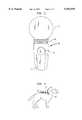
- FIG. 1is a top plan view of a programmable channel search reader constructed in accordance with the invention
- FIG. 2is a front view of the programmable channel search reader scanning a transponder implanted in a pet in accordance with the invention
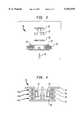
- FIG. 3is an exploded cross-sectional view of the antenna assembly constructed in accordance with the invention.
- FIG. 4is a front elevational cross-sectional view of the antenna assembly constructed in accordance with the invention.
- FIG. 5is a schematic of the circuit for operating the channel search reader constructed in accordance with the invention.
- FIG. 6is a circuit diagram for channel A constructed in accordance with the invention.
- FIG. 7is a circuit diagram for channel B constructed in accordance with the invention.
- FIG. 8is a circuit diagram for channel C constructed in accordance with the invention.
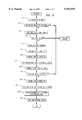
- FIG. 9is a flow chart for programming the channel search reader in accordance with the invention.
- a multichannel reader 10is designed to interrogate passive transponders, including among others, transponders manufactured by Destron, Avid, Trovan, Nedap, Datamars and Texas Instruments to determine and display an identification number stored by each transponder.
- Transponders todayare implanted or otherwise affixed onto a wide variety of animals.
- the veterinarianis unable to read the transponders with a single transceiver, because each manufacturer has designed a different technology, using different (a) methods of modulation, (b) frequencies, and/or (c) methods of encoding with which to output the transponder identification number.
- Table 1 set forth belowdiscloses a sample of the different manufacturers and the different parameters required by each method:
- an identification signalmay include a preamble and data formed as a string of ones and zeros.
- the duration of a binary state(one bit length) is 100 cycles of ⁇ 0 .
- a ZEROis represented by 50 cycles of ⁇ 0 10, followed by 50 cycles at ⁇ 0 /8.
- a ONEis represented by 50 cycles at ⁇ 0 /8 followed by 50 cycles at ⁇ 0 /10.
- An identification telegram portion of the transponder signalcomprises 48 data bits, of which 35 are information bits. The transceiver validates the unique identification code after reception of at least two identical telegrams.
- the transpondersends its message using PSK in the frequency band ⁇ 0 /9.
- the duration of a binary stateis also 100 cycles of ⁇ 0 .
- the messageis Manchester encoded.
- Each transition in the Manchester encoded signalis represented by a 120° phase shift.
- the Manchester transition representing a ZERO of the original messageconsists of a -120° phase shift and that representing a ONE consists of a +120° phase shift.
- the identification telegramcomprises 62 bits of the following structure: 8 synchronization bits (0000 “1” "0” 0) ("1" and "0" are long bits which are 1.5 times longer than normal bits); 48 information bits, divided into 6 blocks of 8 bits; each block is supplemented with a parity (even) bit at the end.
- the transceivervalidates the unique identification code after reception of at least two identical telegrams.
- the encodingis differential biphase. Under this method, a ONE is represented by a phase shift of 0°, while a ZERO is represented by a phase shift of 180°0.
- the duration of a binary stateis 16 cycles of ⁇ 0.
- the transponder identification telegramcomprises 64 bits of the following structure: 8 synchronization bits (01111111); 39 information bits; and 17 error detection bits.
- transponders from a variety of manufacturersutilize a variety of protocols for transmitting information stored in the transponder.
- Reader 10includes a scanner 13 operated by activating a scan button 12 for reading transponders. Scanner 13 is typically positioned on the side of reader 10 opposite scan button 12. Upon processing the information received through scanner 13, which will be described below in greater detail, the information corresponding to the specific transponder is displayed on a liquid crystal display 14 ("LCD 14"). Reader 10 further includes a field programmable serial port 18, which may be linked to a computer by either hardware, RF or the like to edit or enhance the software of reader 10. This operation will also be described in greater detail with reference to FIG. 5.
- reader 10consists of separate transmit antenna 38 and receiver antennas 40,42.
- Receiver antennas 40, 42include two sections which are physically separated and connected in a differential mode as will be described below.
- scanner 13includes a coil assembly 30, disposed in reader 10.
- assembly 30comprises a bobbin 32, an adjustable ferrite plug 34, foam padding 36, one exciter coil 38 and two receive coils 40 and 42.
- Bobbin 32provides three coaxially spaced channels 44a, 44b and 44c for receiving a respective one of exciter coil 38 and receive coils 40 and 42 so that they are fixably wound separate from ferrite plug 34.
- Receive coils 40 and 42are positioned on either side of exciter coil 38, are longitudinally spaced from exciter coil 38 and are coaxial with exciter coil 38.
- Coil assembly 30is mounted in reader 10 by mounting pins 33. Ferrite plugs 34 and foam padding 36 are held in position in bobbin 32 by means of an antenna core insert 48 which is coupled to screw 46.
- Reader 10interrogates transponder 16, by first driving exciter coil 38 with a signal of fixed frequency, a method well-known and developed in the art (see e.g. U.S. Pat. Nos. 5,012,236, 5,041,826, 5,166,676 and 5,250,944).
- exciter coil 38emits an electromagnetic field which complies with and activates transponder 16 and allows transponder to drive the transponder coil with a signal corresponding to the transponder's identification number.
- the transponder's coilemits an electromagnetic field which is picked-up by one or both of receive coils 40 and 42, thereby causing a signal to be induced in the receive coil corresponding to the transponder's identification number.
- each receive coils 40 and 42Due to the proximity of receive coils 40 and 42 to exciter coil 38, the electromagnetic field of the exciter coil 38 induces an equivalent and symmetrical signal in each receive coil 40 and 42. Thus, in the presence of transponder 16, each receive coils 40 and 42 will have induced signals corresponding to the electromagnetic fields emitted by both exciter coil 38 and transponder 16. In other words, the transponder's signal is superimposed on the signal used to drive exciter coil 38.
- the transmitterhas a relatively very high Q at resonance, providing the ability to easily generate large H fields to activate the transponders.
- the separate receive antennasare configured for lower Q or wide band frequency response, tuned to a center frequency midway of the response frequency for all the transponders commonly used in radio frequency identification.
- the receive antennashave a precise means to balance the antennas to a minimum value, thus providing an effective method to cancel the carrier signal, and therefore the resulting signal at the antenna output is predominantly the modulated signal sent by transponders 16 as will be described below.
- Reader 10is controlled by a microprocessor 52 which receives an input and provides outputs to an ASIC chip 72.
- Microprocessor 52drives a liquid crystal display 14 ("LCD 14"), communicates with a serial port 18 and is in two way communication with an EEPROM 74.
- ASIC chip 72provides an output to a driver 54 which drives antenna 38 with the interrogating or exciter signal.
- ASIC chip 72also samples the input received at receive antennas 40, 42.
- a mixer 50receives the input from receive antennas 40, 42 as well as driver 54 and operates on these signals to provide an output microprocessor 52 as well as to a Channel A output and a Channel B output through a serially coupled capacitor 56 and filter 58.
- Channel Aincludes serially coupled bandpass filters 60, 62 which provide an input into comparator 63. The output of comparator 63 is output to ASIC chip 72 as the Channel A.
- Channel Breceives the filter output from filter 58.
- Channel Bincludes a filter 64 for filtering the output of filter 58 and providing an input to a comparator 66.
- Comparator 66provides the output of Channel B which is input to ASIC chip 72.
- a Channel Cincludes an amplifier 60 which receives the input directly from receive antennas 40, 42 and provides an output to comparator 70. Comparator 70 outputs its signal to ASIC chip 72.
- mixer 50The transponder's superimposed signal is received and processed by mixer 50. Because the mixing input frequency is a variable, mixer 50 operates under full control of a microprocessor 52. With this design, mixer 50 may act as a synchronous, non-synchronous or variable phase demodulator as will be described below in greater detail with reference to FIG. 5.
- mixer 50can be fed at any time with different frequencies, with variable phases and intervals as required to demodulate the different transponder signals (a result of the different transponders described above) present at mixer 50.
- the variable phase controlis very important because in many instances the transponder frequency response is not always in phase with the transmitted frequency which, if mixed this way, would result in a poor demodulation.
- the signal outputted from driver 54 used to drive exciter coil 38is "mixed in” with the signals induced in receive coils 40 and 42 by mixer 50.
- This received signalis inputted into mixer 50.
- the resulting mixincludes three components: (1) the original exciter coil signal created by exciter coil in generating an interrogating electromagnetic field, (2) the receive signal generated by transponder 16, and (3) "the mixed in” exciter coil signal (which is identical to the first component). Because of this mixing, the two exciter signals cancel each other, leaving only a recovery signal corresponding to the transponder signal.
- the resulting signalis next filtered.
- the yet unidentified transponder's signalwill have a frequency component falling in the range of 0.5 kHz to 20 kHz in view of the transponder intended to be interrogated and the proposed ISO standards. This information is based on the signal used to drive the exciter coil having a frequency of 125 kHz. In order to exclude signals falling outside this range, reader 10 selects the desired bandwidth by means of different filters used in the channels.
- Table 2set forth below discloses a sample of the different frequency ranges of certain transponders in the marketplace:
- the HDX transpondersends a signal which is half duplex. As a consequence, the signal is not mixed and, is processed along a different path as will be described below.
- the transponder signalis next split into two paths.
- the first path(Channel A) is optimized for FDXA signal recovery and the second path (Channel B) is optimized for FDXB signal recovery.
- the first pathisolates the Avid and Destron transponder signals, for example, by passing the signal through a band pass filter which cuts off signal components having a frequency falling outside the range of 12 to 15.625 kHz.
- the second pathisolates the remaining transponder signals by passing the signal through a low pass filter which cuts-off signal components having a frequency above 10 kHz.
- the frequency content for identification purposes of the signal outputted from mixer 50 for all transpondersis under 20 kHz.
- the outputted signal from mixer 50passes through capacitor 56 to filter 58.
- Filter 58is a low pass filter which limits the frequency content to 20 kHz.
- the output of filter 58then is fed to two separate filter channels A and B.
- Channel Asuppresses the carrier passing signals only between frequencies of 12 to 16 kHz first by means of a 12 kHz band pass filter 60 and then by means of a 16 kHz band pass filter 62 and ultimately to a comparator 63.
- This frequency spectrumcovers transponders for Destron, Avid and Datamars, for example.
- the same signalpasses through a second low pass filter 64 up to 10 kHz to a comparator 66.
- Channel Bwill recover data for transponders in this frequency range, such as Trovan and FDX-B (NEDAP).
- the HDX type of transponderworks differently compared to all other transponders 16 described.
- An HDX transponder 16first stores power transmitted by reader 10 and when reader 10 pauses in transmitting, the HDX transponder 16 sends its data Due to this type of operation of the transponder, the signal is not modulated.
- the binary bitsare FSK (frequency shift keying) encoded only, with 124.2 kHz and 134.2 kHz.
- Reader 10processes the HDX signal without the need of mixer 50 as no demodulation is required
- the receive antennais coupled to an amplifier 68 of Channel C and then fed to comparator 70.
- the comparatorconverts the signal from a sine wave to a square wave and feeds the signal to microprocessor 52 through ASIC 72 when selected.
- the microprocessormeasures the frequency period to determine if the input is either a 124.2 KH or a 134.2 KH.
- Channels A, B and Ceach pass its respective signal through comparator 63, 66 and 70, respectively which reduces the noise associated with this signal.
- Each comparator 63, 66, 70measures the signal's amplitude continuously and compares its hystherisis to a reference voltage of 0.1 volts. If the signal's amplitude is greater than 0.1 volts, the comparator's output is 3 volts. If the signal's amplitude is less than 0.1 volts, the comparator's output is 0 volts.
- the effect of passing the signal through the comparatoris to square-off the signal. Consequently, the rising edges of the signal can be better detected, thus allowing the frequency component of the signal to be accurately measured.
- the frequency discriminatorwhich forms a part of ASIC 72, determines the frequency of the signal at each channel input by measuring one cycle of the squared-off signal using the ASIC's magnitude comparators. Based on this measurement, the frequency and the transponder's manufacturer can be identified using a microprocessor containing the information set forth in Table 2 which will be described below in greater detail. Dependent on the identity of the transponder the signal is then operated upon by software to convert the transponder signal into an identification number to display the tag identification data. After the bits are decoded, microprocessor 52 will then store the ponder telegram and transmit a part of the telegram portion of the transponder signal to LCD 14 to be displayed for the user.
- Mixer 50is connected in series to a capacitor 56 which is connected in series to a resistor 100.
- Resistor 100is coupled to a resistor 102.
- Resistor 102is in parallel with a capacitor 108 and a resistor 106.
- the parallel combinationis connected to ground through a capacitor 104 and coupled to the input of filter 58.
- the other input of filter 58is connected to one-half of the control voltage.
- the output of filter 58is connected in series to a resistor 110 and to the above mentioned parallel combination.
- Resistor 110is connected to a parallel combination of a capacitor 112 in parallel with a resistor 118 and a capacitor 116.
- Resistor 110is further connected to ground through a resistor 114.
- the parallel combinationis connected to the input of filter 60.
- the other input of filer 60is connected to one half of the control voltage.
- the output of filter 60is connected in series to resistor 120 and the parallel combination of capacitor 112, resistor 118 and capacitor 116.
- Resistor 120is coupled to the parallel combination of a capacitor 122 in parallel with a resistor 128 and capacitor 126. Resistor 120 is also connected to ground through resistor 124. The parallel circuit of capacitor 122 with resistor 128 and capacitor 126 is coupled to the input of filter 62. The other input of filter 62 is coupled to one-half of the control voltage. The output of filter 62 is coupled in series to a resistor 130 and the parallel combination of capacitor 122, resistor 128 and capacitor 126. Resistor 130 is coupled to a capacitor 134 which is connected to a resistor 132 connected to the control voltage. Resistor 130 is also coupled to the input of comparator 63. The other input of comparator 63 is connected to resistor 132 and capacitor 134.
- Comparator 63is directly coupled directly to a voltage source and to the same voltage source through capacitor 136. Resistor 132 is further coupled in series to a resistor 138. The output of comparator 63 is coupled to microprocessor 52 through a resistor 140 and to a parallel combination diodes 142 and 144. Diodes 142 and 144 are connected to microprocessor 52 through ASIC 72 and to ground through a resistor 146.
- mixer 50is connected in series to capacitor 56, which is connected in series to resistor 100.
- Resistor 100is then coupled to the parallel combination of resistor 102 in parallel with capacitor 108 and resistor 106.
- This parallel combinationis connected to an input of filter 58.
- Resistor 100is coupled to ground through capacitor 150.
- the other input of filter 58is connected to one-half of the control voltage.
- the output of filter 58is connected in series to a resistor 152 and to the above mentioned parallel combination.
- Resistor 152is coupled to a parallel arrangement of resistor 154 in parallel with a capacitor 160 and a resistor 158. This parallel arrangement is connected to an input of filter 64.
- Resistor 152is also coupled to ground through a capacitor 156.
- the other input of filter 64is connected to a control voltage.
- Filter 64is further coupled to a second control voltage V cc , which is connected to ground through a capacitor 162. Filter 64 is further connected in series to a resistor 164 and the parallel combination of resistor 154, capacitor 160 and resistor 158. Resistor 168 is coupled to the control voltage. A capacitor 170 is positioned between resistors 164 and 168. Resistor 164 is coupled to the input of comparator 66 and resistor 168 is coupled to an input of comparator 66. The output of comparator 66 is coupled to microprocessor 52 through a resistor 174 and to a parallel pair of diodes 176 and 178. Resistor 168 is also coupled to the parallel pair of diodes 176 and 178 through resistor 172. The output of diode 176 and 178 is coupled to ASIC 72.
- a capacitor 200is connected to receive antennas 40 and 42.
- Capacitor 200is coupled to the base of a transistor 205.
- Capacitor 200is also connected to a control voltage through resistor 202.
- Resistor 200is coupled to a resistor 206 to the collector of transistor 205.
- Capacitor 200is further connected to ground through a resistor 204, which is connected in parallel to resistor 208, a resistor 214, a resistor 218 and a resistor 222.
- the emitter of transistor 205is coupled to ground through resistor 208 through ground.
- Resistor 206is coupled to the base of a transistor 215 through a capacitor 210.
- Resistor 206is coupled in parallel to the combination of capacitor 210 and resistor 212. Resistor 212 through a resistor 216 is connected to the collector of transistor 215. The emitter of transistor 215 is connected to ground through resistor 218. Resistor 216 is coupled in series with a capacitor 220 and resistor 222 to ground. Capacitor 220 is connected to the input of comparator 70. The other input of comparator 70 is coupled through a resistor 224 to ground. The output of comparator 70 is connected to microprocessor 52 through a resistor 226. The output of comparator 70 is further coupled to a parallel pair of diodes 228 and 230. The parallel combination of diodes 228 and 230 is further coupled to ASIC 72.
- Reader 10To activate reader 10 during use, scan button 12 is pressed down once and released. Reader 10 will (1) display the version of software operating reader 10 on LCD 14; (2) display remaining battery life on LCD 14; and (3) indicate its ready state on LCD 14. Scan button 12 is then pushed and held down a second time to scan the animal as shown in FIG. 2. Reader 10 is held essentially flat over a transponder 16 implanted in the animal and then moved slowly in a circular direction over transponder 16. When an ID is located, a noise (e.g. a beep) will be outputted by reader 10 followed by the code display on LCD 14 indicating the information stored in transponder 16.
- a noisee.g. a beep
- scan button 12is pressed for activating driver 54 (scan mode).
- Exciter antenna 38receives the signal.
- the signal from driver 54is fed to mixer 50 for processing.
- microprocessor 52automatically starts testing for the presence of transponders. The testing is performed by systematically computing the signal frequency for each type of transponder, this testing occurs over only a few cycles of the wave. If the signal tested is within the response characteristics of any of the transponders, microprocessor 52 will remain in that scan mode until the necessary data length is collected to complete at least 2 to 3 error free telegrams of the transponder.
- scan button 12is pressed for driving driver 54 to provide inputs to exciter antenna 38 and mixer 50.
- the software in microprocessor 52has set the control lines to the various filters, if a transponder 16 is present and the signal received by receive antennas 40, 42 is of sufficient strength, the signal from transponder 16 enters mixer 50 and passes through the band pass filter arrangement of Channel A, the low pass filter arrangement of Channel B and the arrangement of Channel C. Based on the response characteristics discussed above, the activated channel will then process the received signal, while the non-selected channel will effectively ignore the signal.
- the signalsfall into three basic categories: FDXA, FDXB and HDX.
- HDXas described above, is modulated differently and therefore treated differently as processed by Channel C. However, the majority of the other transponders in the marketplace, fall into the category of FDXA or FDXB. The operation of reader 10 for FDXA and FDXB will be described below.
- microprocessor 52When the FDXB read mode is entered, low pass Channel B is selected, the software will search the data port of microprocessor 52 (via ASIC chip 72 by Genesis Ltd.). When the software program finds a pulse that fits within the valid timing for a FDXB signal, microprocessor 52 will convert the phase value of the signal into a bit value. If a normal non-phase changing cycle is found per ISO 11785 standards (16 to 24 cycles leading signal period followed by a trailing cycle of 8 to 16 exciter cycles that has an inverted logic level from the leading signal period), then the bit value for that signal period is set to logic 0. If the non phase changing bit period timing is outside of the expected time, the program will drop out and continue the search for a relevant signal.
- the software of microprocessor 52will store the bit information in a bit stream up to a length of 48 bytes.
- the softwarewill then search for a header.
- a headeris a unique sequence of binary numbers which cannot be found in a data message.
- the headerindicates the start of the telegram and distinguishes the type of transponder (especially if two transponders use the same technology for data transmission).
- the softwareAfter searching and finding the header, the software will perform a string compare to check the integrity of the telegram. Thereafter, the software will verify the data integrity by performing a data format design. After this function, the relevant data is removed and placed in a bit stream for display on LCD 14 of reader 10 and sent to serial part 18, if so programmed, for external data logging and storage.
- band pass filter channel AWhen the processor enters the FDXA reading process, band pass filter channel A is selected, the signal is then fed to a digital phase lock loop type of discriminator implemented in ASIC chip 72. ASIC chip 72 will then set the data line to the processor to a logic "0" signal if the FDXA signal falls under the MID frequency of 14 KHZ. If the signal is above 14 KHZ, the ASIC will set the data line to the processor to a logic "1".
- the application software in microprocessor 52will then test the line by looking for the logic level transitions. If a low to high occurs within the allowed time period for a FDXA signal bit period, the program will store a logic "1" in a bit stream. If a high to low transition occurs within the expected bit period (with a predetermined minimum-to-maximum tolerance) the software will store a logic low in the bit stream. If the expected minimum-to-maximum period times are met, the process continues until a full 48 byte bit stream is filled, if not, then the program will continue its search.
- the software of microprocessor 52will detect the type of header and store this information for the appropriate data process.
- This data streamis parsed out into three strings of data as a function of where it was found in the header.
- the softwarewill then compare these three strings setting any instance of two like compares, as the correct logic level or the bit position where it was found in the data frame.
- the data of the resulting frameis then processed based on the type of header that was found.
- the resulting tag datais then displayed on LCD 14 display. The user may select to have the data sent out of serial port 18 by using the reprogramming function.
- reader 10is its ability to read a plurality of protocols which reader 10 is pre-programed to decode.
- reader 10may be reconfigured from a multi-protocol to a single channel or other formats, providing the benefits of faster speed of reading and provide features as required by the users.
- Reader 10is programmable by the inclusion of a re-programmable EEPROM memory 74 coupled to microprocessor 52.
- EEPROM memory 74may be programmed by any external computer or specialized digital equipment that communicates with reader's 10 internal microprocessor 52 through serial programing port 18 as described below with reference to FIG. 9. Programming is done by a boot load function that resides in processor 52 on-chip mask programmable ROM.
- control hardware of reader 10switches processor 52 into the microcontroller mode of operation at a Step 7.
- the boot programcontrols reader 10.
- the boot functionin the mask programmed ROM) initializes processor's 52 control registers at a Step 7 and if it detects that recent shut down occurred, the boot program will continue by sending the ASCII symbol "ENQ" out of the serial programming port at a Step 3. If a second start after power down is not detected, it will drop out of the boot function and switch directly to the application (transponder reading) program.
- the boot programWhen the boot program detects a second start after a recent power down, it will send a "ENQ" character to the external programming device, looking for a repeating carriage return (CR symbol in ASCII) at a Step 4, if a "CR" symbol is not seen, the boot function defaults to the application program stored on EEPROM 74 located on the reader's PC board. If a CR symbol is found, the reader stays locked into the boot program at a Step 5.
- the external programming devicemust send the control character "0" at a Step 6, indicating that a Motorola S record format containing a number representing the object codes starting memory location is to be placed in its starting address reference table, that will be used to store the program object code to be burned into reprogrammable EEPROM 74.
- the programming processbegins when the operator presses scan button 12, the operator then observes LCD 14 until the word "READY" disappears, the operator must then press button 12 a second time, causing the boot program to continue into the boot program.
- a combination of both hardware and software controlled time-delayed processingproceeds, causing the processors mode of operation hardware to latch a microprocessor state control line at a Step 7. This hardware signal will allow the processor to switch the microprocessor mode under control of the boot program (in the microprocessor mode, the processor runs from EEPROM 74).
- the boot programWhen the boot program begins running, it causes the processor to send out the ASCII symbol "ENQ" at a Step 8.
- the external programming devicefinds an ENQ symbol on the serial line at a Step 9, it begins sending the ASCII symbol for carriage return ("CR") repeatedly at a Step 10. If a CR symbol is not seen at any time that the boot elects to look at the receive line, reader 10 breaks its lock and switches into the application program by dropping its own reset line and causing a reset to the base address of the re-programmable EEPROM 74. If a CR is found on the serial line (by the reader's boot program), the boot microprocessor will continue to operate in the boot program. The external device connected to serial programming port 18 must then send the character "0" in ASCII format at a Step 11.
- Step 12When the boot program finds the character "0", it will then take the next "S" record formatted data that it finds on the serial port, and store the numeric data in a vector table to be used to store the object code that is to be installed at a Step 12.
- reader 10will then send a ACK symbol indicating that it is ready to accept a bum file in Motorola "S" record format.
- the readerthen expects a full and complete Motorola "S” record file to be sent.
- the userthen must place a hardware jumper pin in a programming enable pin socket, to allow for EEPROM memory programming.
- the next data that the reader is sentwill be processed by a burn file, storing the object code portion of this "S" record line, in the first address location that was sent as the offset address process (just described in the last step).
- the boot programcompares the code found in the EEPROM memory (just programmed in) against the code that was sent by the external device at a Step 13, if the code agrees reader 10 will send a ACK signal at a Step 14, this is used to indicate that the memory being programmed has taken the code and that it is in sync with the PC. This process continues until the termination record in the S file has been detected by the reader (per Motorola "S" record standards). When the reader boot program no longer detects a "CR" symbol on the serial port, the boot program will break lock and drops into the microprocessor mode (model #1, 64 kk memory size) with the operational software now residing in external EEPROM memory 74 used to run the program.
- Reprogrammingis used to allow the user to select only specific types of RFID tags to be read, repetitive versus none repetitive modes, special scan modes, improved scan time modes, upgrade features, change the language of LCD 14 or the like.
Landscapes
- Engineering & Computer Science (AREA)
- Physics & Mathematics (AREA)
- Computer Vision & Pattern Recognition (AREA)
- Health & Medical Sciences (AREA)
- Toxicology (AREA)
- Artificial Intelligence (AREA)
- General Physics & Mathematics (AREA)
- Theoretical Computer Science (AREA)
- Computer Security & Cryptography (AREA)
- Electromagnetism (AREA)
- General Health & Medical Sciences (AREA)
- Computer Networks & Wireless Communication (AREA)
- Radar Systems Or Details Thereof (AREA)
Abstract
Description
TABLE 1__________________________________________________________________________ TX Data DataTYPE Frequency Modulation BIT Encoding Encoding Bit Rate Encription__________________________________________________________________________Destron 125 kHz AM FSK Manchester 2500 BPS NoFECAVA fo/8, fo/10Avid-USA 125 kHz AM FSK NRZ 2500 BPS Yes fo/8, fo/10Trovan 128 kHz AM FSK BP 8 K BPS No fo/2-PhaseDatamars 125 kHz AM FSK Manchester 2500 BPS No fo/9-PhaseFDX-B 134.2 kHz AM PSK MDBP 4.4 K BPS NoHDX 134.2 kHz None FSK NRZ 8.39 K BPS NoHalf Duplex 124.2 kHz and 134.2 kHz__________________________________________________________________________
TABLE 2______________________________________Frequency of Transponder Signal Manufacturer of Transponder______________________________________124.2-134.3 kHz HDX 0.558-3.90635 kHz Trovan1.563-7.825 kHz NeDap12.5/15.6 kHz Avid12.5/15/6 kHz Destron______________________________________
Claims (21)
Priority Applications (1)
| Application Number | Priority Date | Filing Date | Title |
|---|---|---|---|
| US08/735,763US5952935A (en) | 1996-05-03 | 1996-10-23 | Programmable channel search reader |
Applications Claiming Priority (2)
| Application Number | Priority Date | Filing Date | Title |
|---|---|---|---|
| US1680896P | 1996-05-03 | 1996-05-03 | |
| US08/735,763US5952935A (en) | 1996-05-03 | 1996-10-23 | Programmable channel search reader |
Publications (1)
| Publication Number | Publication Date |
|---|---|
| US5952935Atrue US5952935A (en) | 1999-09-14 |
Family
ID=26689094
Family Applications (1)
| Application Number | Title | Priority Date | Filing Date |
|---|---|---|---|
| US08/735,763Expired - LifetimeUS5952935A (en) | 1996-05-03 | 1996-10-23 | Programmable channel search reader |
Country Status (1)
| Country | Link |
|---|---|
| US (1) | US5952935A (en) |
Cited By (87)
| Publication number | Priority date | Publication date | Assignee | Title |
|---|---|---|---|---|
| WO2000077717A1 (en)* | 1999-06-10 | 2000-12-21 | Cubic Corporation | Multiple protocol smart card communication device |
| WO2001050407A1 (en)* | 2000-01-06 | 2001-07-12 | Samsys Incorporated | A system for multi-standard rfid tags |
| US6275153B1 (en) | 2000-07-26 | 2001-08-14 | Andrew Brooks | Identification and tracking system |
| US6400272B1 (en)* | 1999-04-01 | 2002-06-04 | Presto Technologies, Inc. | Wireless transceiver for communicating with tags |
| US6411199B1 (en)* | 1998-08-21 | 2002-06-25 | Keri Systems, Inc. | Radio frequency identification system |
| US6611224B1 (en) | 1997-08-18 | 2003-08-26 | X-Cyte, Inc. | Backscatter transponder interrogation device |
| WO2003085617A1 (en)* | 2002-04-02 | 2003-10-16 | Digital Angel Corporation | Method and apparatus for sensing and transmitting a body characteristic of a host |
| US6683527B1 (en)* | 1998-08-20 | 2004-01-27 | Land Rover | Security system |
| US6700547B2 (en) | 2002-04-12 | 2004-03-02 | Digital Angel Corporation | Multidirectional walkthrough antenna |
| US20040067764A1 (en)* | 2002-10-02 | 2004-04-08 | Pratt Richard M. | Wireless communications devices, methods of processing a wireless communication signal, wireless communication synchronization methods and a radio frequency identification device communication method |
| US6720930B2 (en) | 2001-01-16 | 2004-04-13 | Digital Angel Corporation | Omnidirectional RFID antenna |
| US20040085207A1 (en)* | 2002-10-30 | 2004-05-06 | Barrett Kreiner | Method for monitoring and tracking objects |
| US20040084525A1 (en)* | 2002-10-30 | 2004-05-06 | Barrett Kreiner | System for monitoring and tracking objects |
| US20040160322A1 (en)* | 2003-02-03 | 2004-08-19 | Stilp Louis A. | RFID reader for a security system |
| US20040160306A1 (en)* | 2003-02-03 | 2004-08-19 | Stilp Louis A. | Device enrollment in a security system |
| US20040160309A1 (en)* | 2003-02-03 | 2004-08-19 | Stilp Louis A. | Communications control in a security system |
| US20040212503A1 (en)* | 2003-02-03 | 2004-10-28 | Stilp Louis A. | Communications architecture for a security network |
| US20040212494A1 (en)* | 2003-02-03 | 2004-10-28 | Stilp Louis A. | Cordless telephone system |
| USD499975S1 (en) | 2003-09-25 | 2004-12-21 | Basix Holdings Llc | Object locator |
| US6833790B2 (en) | 2002-04-12 | 2004-12-21 | Digital Angel Corporation | Livestock chute scanner |
| US20050200478A1 (en)* | 2002-10-30 | 2005-09-15 | Bellsouth Intellectual Property Corporation | Instantaneous mobile access to all pertinent life events |
| US20050225447A1 (en)* | 2004-04-13 | 2005-10-13 | Impinj, Inc., A Delaware Corporation | RFID readers transmitting preambles denoting communication parameters and RFID tags interpreting the same and methods |
| US20050225435A1 (en)* | 2004-04-13 | 2005-10-13 | Impinj, Inc. | Adaptable bandwidth RFID tags |
| US20050230475A1 (en)* | 2004-04-16 | 2005-10-20 | Denso Wave Incorporated | Information carrier reader/writer, method and apparatus for supporting the same |
| US20050237162A1 (en)* | 2004-04-13 | 2005-10-27 | Impinj, Inc., A Delaware Corporation | RFID readers transmitting preambles denoting data rate and methods |
| US20050280510A1 (en)* | 2004-06-16 | 2005-12-22 | Gemplus | Synchronous-phase contactless demodulation method, and associated demodulator and reader |
| US20060145855A1 (en)* | 2003-11-10 | 2006-07-06 | Impinj, Inc. | RFID reader to select code modules |
| US7079034B2 (en) | 2003-02-03 | 2006-07-18 | Ingrid, Inc. | RFID transponder for a security system |
| US20060202835A1 (en)* | 2005-02-25 | 2006-09-14 | Osborne Industries, Inc. | Dual frequency identification device |
| US20060224893A1 (en)* | 2005-04-04 | 2006-10-05 | Intermec Ip Corp. | Secure wireless communication apparatus and method for electronic devices incorporating pushed pins |
| US20060267733A1 (en)* | 2005-05-27 | 2006-11-30 | Psc Scanning, Inc. | Apparatus and methods for saving power in RFID readers |
| US20070046438A1 (en)* | 2005-08-29 | 2007-03-01 | Mark Pempsell | Electronic Radio Frequency Identification Transceiver Device Activated by Radiant Means |
| US20070046470A1 (en)* | 2005-08-29 | 2007-03-01 | Mark Pempsell | Hybrid Acousto-Magnetic Radio Frequency Transceiver Device |
| US20070057057A1 (en)* | 2005-09-09 | 2007-03-15 | Assa Abloy Identification Technology Group Ab | Synchronization techniques in multi-technology/multi-frequency rfid reader arrays |
| US20070126584A1 (en)* | 2004-04-13 | 2007-06-07 | Impimj, Inc. | Adaptable Detection Threshold for RFID Tags and Chips |
| US7283048B2 (en) | 2003-02-03 | 2007-10-16 | Ingrid, Inc. | Multi-level meshed security network |
| US20080104010A1 (en)* | 2006-10-31 | 2008-05-01 | Symbol Technologies, Inc. | Configuring initialized RFID readers using RFID tags |
| US20080100430A1 (en)* | 2006-10-30 | 2008-05-01 | Robert Kochie | Tire pressure monitor system tool with vehicle entry system |
| US20080103718A1 (en)* | 2006-10-30 | 2008-05-01 | Garret Miller | Tire pressure monitor initiation tool with vehicle data interface |
| US20080143506A1 (en)* | 2006-10-30 | 2008-06-19 | Robert Kochie | Tire pressure monitor system module |
| US20080281190A1 (en)* | 2006-01-25 | 2008-11-13 | Health Beacons, Inc. | Surgical procedures |
| US20080278328A1 (en)* | 2005-07-20 | 2008-11-13 | Rockwell Automation Technologies, Inc. | Mobile rfid reader with integrated location awareness for material tracking and management |
| US7464001B1 (en)* | 2004-09-11 | 2008-12-09 | French Creek Production, Inc. | Method of identifying and recording inspection information on personal protective equipment |
| US20090009292A1 (en)* | 2007-05-18 | 2009-01-08 | Cambridge Resonant Technologies Ltd. | Rfid interrogator |
| US20090021362A1 (en)* | 2006-10-30 | 2009-01-22 | Robert Kochie | Tire pressure monitor system tool with re-learn and diagnostic procedures |
| US20090045913A1 (en)* | 2007-08-16 | 2009-02-19 | Farpointe Data, Inc., A California Corporation | System and method for interrogation radio-frequency identification |
| US20090045921A1 (en)* | 2007-08-16 | 2009-02-19 | Farpointe Data, Inc., A California Corporation | System and method for multi-protocol radio-frequency identification |
| US7495544B2 (en) | 2003-02-03 | 2009-02-24 | Ingrid, Inc. | Component diversity in a RFID security network |
| US20090058600A1 (en)* | 2007-08-31 | 2009-03-05 | 3M Innovative Properties Company | Determining compatibility of components for assembling approved personal protection configurations |
| US7511614B2 (en) | 2003-02-03 | 2009-03-31 | Ingrid, Inc. | Portable telephone in a security network |
| US7532114B2 (en) | 2003-02-03 | 2009-05-12 | Ingrid, Inc. | Fixed part-portable part communications network for a security network |
| US20090206154A1 (en)* | 2005-09-08 | 2009-08-20 | Rockwell Automation Technologies, Inc. | Rfid architecture in an industrial controller environment |
| WO2009090426A3 (en)* | 2008-01-17 | 2009-09-11 | Cambridge Resonant Technologies Ltd | Improved rfid pet door |
| US20090267751A1 (en)* | 2008-04-23 | 2009-10-29 | Bill Wittliff | Tire Pressure Monitor System Tool with Parts Number Database |
| US20090278667A1 (en)* | 2008-05-07 | 2009-11-12 | Mstar Semiconductor, Inc. | Method and Computer Program Product for Loading and Executing Program Code at Micro-processor |
| US20100182133A1 (en)* | 2007-06-28 | 2010-07-22 | The Nippon Signal Co., Ltd. | Reader/writer and article sorting system |
| US7764191B2 (en) | 2005-07-26 | 2010-07-27 | Rockwell Automation Technologies, Inc. | RFID tag data affecting automation controller with internal database |
| US7772978B1 (en) | 2005-09-26 | 2010-08-10 | Rockwell Automation Technologies, Inc. | Intelligent RFID tag for magnetic field mapping |
| US20100207765A1 (en)* | 2009-02-13 | 2010-08-19 | Christopher Brander | Method and apparatus for locating passive integrated transponder tags |
| US20100238042A1 (en)* | 2009-03-19 | 2010-09-23 | Gary Paul | Dental fixture with anti-lost system |
| US20100243737A1 (en)* | 2009-03-31 | 2010-09-30 | Infineon Technologies Ag | Contactless data reception |
| US20100276487A1 (en)* | 2006-08-16 | 2010-11-04 | Isonas Security Systems | Method and system for controlling access to an enclosed area |
| USRE41916E1 (en) | 1998-05-14 | 2010-11-09 | Round Rock Research, Llc | Wireless communication systems, interfacing devices, communication methods, methods of interfacing with an interrogator, and methods of operating an interrogator |
| US7932813B2 (en) | 2007-05-03 | 2011-04-26 | Rf Ideas, Inc. | Sampling to obtain signal from RFID card |
| US7931197B2 (en) | 2005-09-20 | 2011-04-26 | Rockwell Automation Technologies, Inc. | RFID-based product manufacturing and lifecycle management |
| US20110148591A1 (en)* | 2002-05-30 | 2011-06-23 | Reynolds Matthew S | Methods and apparatus for operating a radio device |
| US7994919B2 (en) | 2004-11-10 | 2011-08-09 | Rockwell Automation Technologies, Inc. | Systems and methods that integrate radio frequency identification (RFID) technology with agent-based control systems |
| US7997475B2 (en) | 2004-11-10 | 2011-08-16 | Rockwell Automation Technologies, Inc. | Systems and methods that integrate radio frequency identification (RFID) technology with industrial controllers |
| US20110205026A1 (en)* | 2009-10-09 | 2011-08-25 | Leigh Bateman | Radio frequency identification reader antenna having a dynamically adjustable q-factor |
| US20110210824A1 (en)* | 2009-11-04 | 2011-09-01 | Allflex Usa, Inc. | Signal cancelling transmit/receive multi-loop antenna for a radio frequency identification reader |
| US20110210823A1 (en)* | 2009-10-09 | 2011-09-01 | Leigh Bateman | Hdx demodulator |
| US8025227B2 (en) | 2005-09-30 | 2011-09-27 | Rockwell Automation Technologies, Inc. | Access to distributed databases via pointer stored in RFID tag |
| US8260948B2 (en) | 2005-08-10 | 2012-09-04 | Rockwell Automation Technologies, Inc. | Enhanced controller utilizing RFID technology |
| WO2012131337A1 (en)* | 2011-03-25 | 2012-10-04 | Mbda Uk Limited | An rf communication method and apparatus |
| US8358783B2 (en) | 2008-08-11 | 2013-01-22 | Assa Abloy Ab | Secure wiegand communications |
| US20130120122A1 (en)* | 2011-11-16 | 2013-05-16 | Schneider Electric Industries Sas | Method and system for the secure detection of an rfid electronic tag |
| US8939153B1 (en) | 2013-03-15 | 2015-01-27 | Health Beacons, Inc. | Transponder strings |
| US9091537B2 (en) | 2012-04-18 | 2015-07-28 | Bosch Automotive Service Solutions Inc. | Tire pressure monitor system tool with active tire pressure display |
| US9153083B2 (en) | 2010-07-09 | 2015-10-06 | Isonas, Inc. | System and method for integrating and adapting security control systems |
| US9563794B2 (en) | 2011-03-17 | 2017-02-07 | Assa Abloy Ab | Method for upgrading RFID readers in situ |
| US9589400B2 (en) | 2006-08-16 | 2017-03-07 | Isonas, Inc. | Security control and access system |
| US9646239B2 (en) | 2008-09-04 | 2017-05-09 | Allflex Usa, Inc. | Combination full-duplex and half-duplex electronic identification tag |
| US10154649B2 (en) | 2005-12-16 | 2018-12-18 | Cambridge Resonant Technologies Ltd. | RFID reader |
| US10452877B2 (en) | 2016-12-16 | 2019-10-22 | Assa Abloy Ab | Methods to combine and auto-configure wiegand and RS485 |
| US11557163B2 (en) | 2006-08-16 | 2023-01-17 | Isonas, Inc. | System and method for integrating and adapting security control systems |
| US11934908B2 (en) | 2019-09-03 | 2024-03-19 | Y Soft Corporation | Device for detection of a signal of passive chips and method for operating the device |
| US11998306B2 (en) | 2014-08-24 | 2024-06-04 | Health Beacons, Inc. | Probe for determining magnetic marker locations |
Citations (3)
| Publication number | Priority date | Publication date | Assignee | Title |
|---|---|---|---|---|
| US5451958A (en)* | 1993-05-21 | 1995-09-19 | Texas Instruments Deutschland Gmbh | Dual standard RF-ID system |
| US5519381A (en)* | 1992-11-18 | 1996-05-21 | British Technology Group Limited | Detection of multiple articles |
| US5521602A (en)* | 1994-02-10 | 1996-05-28 | Racom Systems, Inc. | Communications system utilizing FSK/PSK modulation techniques |
- 1996
- 1996-10-23USUS08/735,763patent/US5952935A/ennot_activeExpired - Lifetime
Patent Citations (3)
| Publication number | Priority date | Publication date | Assignee | Title |
|---|---|---|---|---|
| US5519381A (en)* | 1992-11-18 | 1996-05-21 | British Technology Group Limited | Detection of multiple articles |
| US5451958A (en)* | 1993-05-21 | 1995-09-19 | Texas Instruments Deutschland Gmbh | Dual standard RF-ID system |
| US5521602A (en)* | 1994-02-10 | 1996-05-28 | Racom Systems, Inc. | Communications system utilizing FSK/PSK modulation techniques |
Cited By (182)
| Publication number | Priority date | Publication date | Assignee | Title |
|---|---|---|---|---|
| US6611224B1 (en) | 1997-08-18 | 2003-08-26 | X-Cyte, Inc. | Backscatter transponder interrogation device |
| USRE43313E1 (en) | 1998-05-14 | 2012-04-17 | Round Rock Research, Llc | Wireless communication systems and methods |
| USRE41916E1 (en) | 1998-05-14 | 2010-11-09 | Round Rock Research, Llc | Wireless communication systems, interfacing devices, communication methods, methods of interfacing with an interrogator, and methods of operating an interrogator |
| US6683527B1 (en)* | 1998-08-20 | 2004-01-27 | Land Rover | Security system |
| US6411199B1 (en)* | 1998-08-21 | 2002-06-25 | Keri Systems, Inc. | Radio frequency identification system |
| US6400272B1 (en)* | 1999-04-01 | 2002-06-04 | Presto Technologies, Inc. | Wireless transceiver for communicating with tags |
| US7227449B2 (en) | 1999-06-10 | 2007-06-05 | Cubic Corporation | Multiple protocol smart card communication device |
| US6577229B1 (en) | 1999-06-10 | 2003-06-10 | Cubic Corporation | Multiple protocol smart card communication device |
| US20030137404A1 (en)* | 1999-06-10 | 2003-07-24 | Bonneau Walter C. | Multiple protocol smart card communication device |
| WO2000077717A1 (en)* | 1999-06-10 | 2000-12-21 | Cubic Corporation | Multiple protocol smart card communication device |
| US20080055048A1 (en)* | 1999-06-10 | 2008-03-06 | Cubic Corporation | Multiple Protocol Smart Card Communication Device |
| US7116212B2 (en) | 2000-01-06 | 2006-10-03 | Sirit Technologies Inc. | System for multi-standard RFID tags |
| US7196613B2 (en) | 2000-01-06 | 2007-03-27 | Sirit Technologies Inc. | System for multi-standard RFID tags |
| US20050083180A1 (en)* | 2000-01-06 | 2005-04-21 | Horwitz Clifford A. | System for multi-standard RFID tags |
| US6617962B1 (en) | 2000-01-06 | 2003-09-09 | Samsys Technologies Inc. | System for multi-standard RFID tags |
| US20040085191A1 (en)* | 2000-01-06 | 2004-05-06 | Horwitz Clifford A. | System for multi-standard RFID tags |
| WO2001050407A1 (en)* | 2000-01-06 | 2001-07-12 | Samsys Incorporated | A system for multi-standard rfid tags |
| US6275153B1 (en) | 2000-07-26 | 2001-08-14 | Andrew Brooks | Identification and tracking system |
| US6720930B2 (en) | 2001-01-16 | 2004-04-13 | Digital Angel Corporation | Omnidirectional RFID antenna |
| US7432825B2 (en) | 2002-04-02 | 2008-10-07 | Destron Fearing Corporation | Interrogation device and method for scanning |
| WO2003085617A1 (en)* | 2002-04-02 | 2003-10-16 | Digital Angel Corporation | Method and apparatus for sensing and transmitting a body characteristic of a host |
| US7015826B1 (en)* | 2002-04-02 | 2006-03-21 | Digital Angel Corporation | Method and apparatus for sensing and transmitting a body characteristic of a host |
| US20040036626A1 (en)* | 2002-04-02 | 2004-02-26 | Chan Vincent K. | Interrogation device and method for scanning |
| AU2003225811B2 (en)* | 2002-04-02 | 2008-09-18 | Destron Fearing Corporation | Method and apparatus for sensing and transmitting a body characteristic of a host |
| US6700547B2 (en) | 2002-04-12 | 2004-03-02 | Digital Angel Corporation | Multidirectional walkthrough antenna |
| US6833790B2 (en) | 2002-04-12 | 2004-12-21 | Digital Angel Corporation | Livestock chute scanner |
| US20110148591A1 (en)* | 2002-05-30 | 2011-06-23 | Reynolds Matthew S | Methods and apparatus for operating a radio device |
| US8330580B2 (en)* | 2002-05-30 | 2012-12-11 | Trimble Navigation Limited | Methods and apparatus for operating a radio device |
| US7760835B2 (en)* | 2002-10-02 | 2010-07-20 | Battelle Memorial Institute | Wireless communications devices, methods of processing a wireless communication signal, wireless communication synchronization methods and a radio frequency identification device communication method |
| US8218703B2 (en) | 2002-10-02 | 2012-07-10 | Battelle Memorial Institute | Methods of processing a wireless communication signal, wireless communication synchronization methods, and a radio frequency identification device communication method |
| US20040067764A1 (en)* | 2002-10-02 | 2004-04-08 | Pratt Richard M. | Wireless communications devices, methods of processing a wireless communication signal, wireless communication synchronization methods and a radio frequency identification device communication method |
| US8896422B2 (en) | 2002-10-30 | 2014-11-25 | At&T Intellectual Property I, L.P. | Methods, systems, and products for tracking objects |
| US9697398B2 (en) | 2002-10-30 | 2017-07-04 | At&T Intellectual Property I, L.P. | Methods, systems, and products for tracking objects |
| US20090111484A1 (en)* | 2002-10-30 | 2009-04-30 | Robert Koch | Methods, Systems, and Products for Tracking Objects |
| US20050200478A1 (en)* | 2002-10-30 | 2005-09-15 | Bellsouth Intellectual Property Corporation | Instantaneous mobile access to all pertinent life events |
| US6900731B2 (en) | 2002-10-30 | 2005-05-31 | Bellsouth Intellectual Property Corporation | Method for monitoring and tracking objects |
| US10740579B2 (en) | 2002-10-30 | 2020-08-11 | At&T Intellectual Property I, L.P. | Methods, systems, and products for tracking objects |
| US20040084525A1 (en)* | 2002-10-30 | 2004-05-06 | Barrett Kreiner | System for monitoring and tracking objects |
| US7274295B2 (en) | 2002-10-30 | 2007-09-25 | At&T Bls Intellectual Property, Inc. | Instantaneous mobile access to all pertinent life events |
| US20040085207A1 (en)* | 2002-10-30 | 2004-05-06 | Barrett Kreiner | Method for monitoring and tracking objects |
| US7202789B1 (en) | 2003-02-03 | 2007-04-10 | Ingrid, Inc. | Clip for RFID transponder of a security network |
| US7057512B2 (en) | 2003-02-03 | 2006-06-06 | Ingrid, Inc. | RFID reader for a security system |
| US7091827B2 (en)* | 2003-02-03 | 2006-08-15 | Ingrid, Inc. | Communications control in a security system |
| US20040160322A1 (en)* | 2003-02-03 | 2004-08-19 | Stilp Louis A. | RFID reader for a security system |
| US7079034B2 (en) | 2003-02-03 | 2006-07-18 | Ingrid, Inc. | RFID transponder for a security system |
| US20040160306A1 (en)* | 2003-02-03 | 2004-08-19 | Stilp Louis A. | Device enrollment in a security system |
| US7119658B2 (en) | 2003-02-03 | 2006-10-10 | Ingrid, Inc. | Device enrollment in a security system |
| US20040160309A1 (en)* | 2003-02-03 | 2004-08-19 | Stilp Louis A. | Communications control in a security system |
| US20040212503A1 (en)* | 2003-02-03 | 2004-10-28 | Stilp Louis A. | Communications architecture for a security network |
| US20040212497A1 (en)* | 2003-02-03 | 2004-10-28 | Stilp Louis A. | Multi-controller security network |
| US20040212494A1 (en)* | 2003-02-03 | 2004-10-28 | Stilp Louis A. | Cordless telephone system |
| US7084756B2 (en) | 2003-02-03 | 2006-08-01 | Ingrid, Inc. | Communications architecture for a security network |
| US7079020B2 (en) | 2003-02-03 | 2006-07-18 | Ingrid, Inc. | Multi-controller security network |
| US7532114B2 (en) | 2003-02-03 | 2009-05-12 | Ingrid, Inc. | Fixed part-portable part communications network for a security network |
| US7042353B2 (en) | 2003-02-03 | 2006-05-09 | Ingrid, Inc. | Cordless telephone system |
| US7511614B2 (en) | 2003-02-03 | 2009-03-31 | Ingrid, Inc. | Portable telephone in a security network |
| US7495544B2 (en) | 2003-02-03 | 2009-02-24 | Ingrid, Inc. | Component diversity in a RFID security network |
| US7283048B2 (en) | 2003-02-03 | 2007-10-16 | Ingrid, Inc. | Multi-level meshed security network |
| USD499975S1 (en) | 2003-09-25 | 2004-12-21 | Basix Holdings Llc | Object locator |
| US7304579B2 (en) | 2003-11-10 | 2007-12-04 | Impinj, Inc. | RFID reader to select code modules |
| US20060145855A1 (en)* | 2003-11-10 | 2006-07-06 | Impinj, Inc. | RFID reader to select code modules |
| US7501953B2 (en) | 2004-04-13 | 2009-03-10 | Impinj Inc | RFID readers transmitting preambles denoting communication parameters and RFID tags interpreting the same and methods |
| US7917088B2 (en) | 2004-04-13 | 2011-03-29 | Impinj, Inc. | Adaptable detection threshold for RFID tags and chips |
| US8258955B1 (en) | 2004-04-13 | 2012-09-04 | Impinj, Inc. | Adaptable detection threshold for RFID tags and chips |
| US7183926B2 (en) | 2004-04-13 | 2007-02-27 | Impinj, Inc. | Adaptable bandwidth RFID tags |
| US20050225447A1 (en)* | 2004-04-13 | 2005-10-13 | Impinj, Inc., A Delaware Corporation | RFID readers transmitting preambles denoting communication parameters and RFID tags interpreting the same and methods |
| US20050237162A1 (en)* | 2004-04-13 | 2005-10-27 | Impinj, Inc., A Delaware Corporation | RFID readers transmitting preambles denoting data rate and methods |
| US20050225435A1 (en)* | 2004-04-13 | 2005-10-13 | Impinj, Inc. | Adaptable bandwidth RFID tags |
| US7973643B2 (en) | 2004-04-13 | 2011-07-05 | Impinj, Inc. | RFID readers transmitting preambles denoting data rate and methods |
| US20070126584A1 (en)* | 2004-04-13 | 2007-06-07 | Impimj, Inc. | Adaptable Detection Threshold for RFID Tags and Chips |
| US20050230475A1 (en)* | 2004-04-16 | 2005-10-20 | Denso Wave Incorporated | Information carrier reader/writer, method and apparatus for supporting the same |
| US7357320B2 (en) | 2004-04-16 | 2008-04-15 | Denso Wave Incorporated | Information carrier reader/writer, method and apparatus for supporting the same |
| FR2869437A1 (en)* | 2004-04-16 | 2005-10-28 | Denso Wave Inc | READER / WRITE DEVICE FOR INFORMATION CARRIER ASSOCIATED METHODS AND APPARATUS |
| US20050280510A1 (en)* | 2004-06-16 | 2005-12-22 | Gemplus | Synchronous-phase contactless demodulation method, and associated demodulator and reader |
| US8154388B2 (en)* | 2004-06-16 | 2012-04-10 | Gemalto Sa | Synchronous-phase contactless demodulation method, and associated demodulator and reader |
| US7464001B1 (en)* | 2004-09-11 | 2008-12-09 | French Creek Production, Inc. | Method of identifying and recording inspection information on personal protective equipment |
| US7994919B2 (en) | 2004-11-10 | 2011-08-09 | Rockwell Automation Technologies, Inc. | Systems and methods that integrate radio frequency identification (RFID) technology with agent-based control systems |
| US8384544B2 (en) | 2004-11-10 | 2013-02-26 | Rockwell Automation Technologies, Inc. | Systems and methods that integrate radio frequency identification (RFID) technology with agent-based control systems |
| US7997475B2 (en) | 2004-11-10 | 2011-08-16 | Rockwell Automation Technologies, Inc. | Systems and methods that integrate radio frequency identification (RFID) technology with industrial controllers |
| US20060202835A1 (en)* | 2005-02-25 | 2006-09-14 | Osborne Industries, Inc. | Dual frequency identification device |
| US20060224893A1 (en)* | 2005-04-04 | 2006-10-05 | Intermec Ip Corp. | Secure wireless communication apparatus and method for electronic devices incorporating pushed pins |
| US20060267733A1 (en)* | 2005-05-27 | 2006-11-30 | Psc Scanning, Inc. | Apparatus and methods for saving power in RFID readers |
| US20080278328A1 (en)* | 2005-07-20 | 2008-11-13 | Rockwell Automation Technologies, Inc. | Mobile rfid reader with integrated location awareness for material tracking and management |
| US7932827B2 (en) | 2005-07-20 | 2011-04-26 | Rockwell Automation Technologies, Inc. | Mobile RFID reader with integrated location awareness for material tracking and management |
| US7764191B2 (en) | 2005-07-26 | 2010-07-27 | Rockwell Automation Technologies, Inc. | RFID tag data affecting automation controller with internal database |
| US8260948B2 (en) | 2005-08-10 | 2012-09-04 | Rockwell Automation Technologies, Inc. | Enhanced controller utilizing RFID technology |
| US20070046470A1 (en)* | 2005-08-29 | 2007-03-01 | Mark Pempsell | Hybrid Acousto-Magnetic Radio Frequency Transceiver Device |
| US20070046438A1 (en)* | 2005-08-29 | 2007-03-01 | Mark Pempsell | Electronic Radio Frequency Identification Transceiver Device Activated by Radiant Means |
| US8152053B2 (en) | 2005-09-08 | 2012-04-10 | Rockwell Automation Technologies, Inc. | RFID architecture in an industrial controller environment |
| US20090206154A1 (en)* | 2005-09-08 | 2009-08-20 | Rockwell Automation Technologies, Inc. | Rfid architecture in an industrial controller environment |
| US8967476B2 (en) | 2005-09-09 | 2015-03-03 | Assa Abloy Ab | Synchronization techniques in multi-technology/multi-frequency RFID reader arrays |
| US20070057057A1 (en)* | 2005-09-09 | 2007-03-15 | Assa Abloy Identification Technology Group Ab | Synchronization techniques in multi-technology/multi-frequency rfid reader arrays |
| US7931197B2 (en) | 2005-09-20 | 2011-04-26 | Rockwell Automation Technologies, Inc. | RFID-based product manufacturing and lifecycle management |
| US7772978B1 (en) | 2005-09-26 | 2010-08-10 | Rockwell Automation Technologies, Inc. | Intelligent RFID tag for magnetic field mapping |
| US8025227B2 (en) | 2005-09-30 | 2011-09-27 | Rockwell Automation Technologies, Inc. | Access to distributed databases via pointer stored in RFID tag |
| US10154649B2 (en) | 2005-12-16 | 2018-12-18 | Cambridge Resonant Technologies Ltd. | RFID reader |
| US20080281190A1 (en)* | 2006-01-25 | 2008-11-13 | Health Beacons, Inc. | Surgical procedures |
| US11557163B2 (en) | 2006-08-16 | 2023-01-17 | Isonas, Inc. | System and method for integrating and adapting security control systems |
| US9558606B2 (en) | 2006-08-16 | 2017-01-31 | Isonas, Inc. | System and method for integrating and adapting security control systems |
| US20100276487A1 (en)* | 2006-08-16 | 2010-11-04 | Isonas Security Systems | Method and system for controlling access to an enclosed area |
| US9589400B2 (en) | 2006-08-16 | 2017-03-07 | Isonas, Inc. | Security control and access system |
| US9972152B2 (en) | 2006-08-16 | 2018-05-15 | Isonas, Inc. | System and method for integrating and adapting security control systems |
| US8662386B2 (en) | 2006-08-16 | 2014-03-04 | Isonas Security Systems, Inc. | Method and system for controlling access to an enclosed area |
| US11341797B2 (en) | 2006-08-16 | 2022-05-24 | Isonas, Inc. | Security control and access system |
| US10269197B2 (en) | 2006-08-16 | 2019-04-23 | Isonas, Inc. | System and method for integrating and adapting security control systems |
| US10388090B2 (en) | 2006-08-16 | 2019-08-20 | Isonas, Inc. | Security control and access system |
| US10699504B2 (en) | 2006-08-16 | 2020-06-30 | Isonas, Inc. | System and method for integrating and adapting security control systems |
| US9336633B2 (en) | 2006-08-16 | 2016-05-10 | Isonas, Inc. | Security control access system |
| US11094154B2 (en) | 2006-08-16 | 2021-08-17 | Isonas, Inc. | System and method for integrating and adapting security control systems |
| US20100066525A1 (en)* | 2006-10-30 | 2010-03-18 | Robert Kochie | Tire Pressure Monitor System Tool with Re-Learn and Diagnostic Procedures |
| US20100085177A1 (en)* | 2006-10-30 | 2010-04-08 | Robert Kochie | Tire Pressure Monitor System Tool with Vehicle Entry System |
| US7623025B2 (en) | 2006-10-30 | 2009-11-24 | Spx Corporation | Tire pressure monitor initiation tool with vehicle data interface |
| US7639122B2 (en) | 2006-10-30 | 2009-12-29 | Spx Corporation | Tire pressure monitor system tool with vehicle entry system |
| US20080100430A1 (en)* | 2006-10-30 | 2008-05-01 | Robert Kochie | Tire pressure monitor system tool with vehicle entry system |
| US8570165B2 (en) | 2006-10-30 | 2013-10-29 | Service Solutions U.S. Llc | Tire pressure monitor system tool with re-learn and diagnostic procedures |
| US7592903B2 (en) | 2006-10-30 | 2009-09-22 | Spx Corporation | Tire pressure monitor system tool with re-learn and diagnostic procedures |
| US8035499B2 (en) | 2006-10-30 | 2011-10-11 | Spx Corporation | Tire pressure monitor system module |
| US8058979B2 (en) | 2006-10-30 | 2011-11-15 | Spx Corporation | Tire pressure monitor initiation tool with vehicle data interface |
| US8072320B2 (en) | 2006-10-30 | 2011-12-06 | Spx Corporation | Tire pressure monitor system tool with vehicle entry system |
| US20090021362A1 (en)* | 2006-10-30 | 2009-01-22 | Robert Kochie | Tire pressure monitor system tool with re-learn and diagnostic procedures |
| US9269201B2 (en) | 2006-10-30 | 2016-02-23 | Bosch Automotive Service Solutions Inc. | Tire pressure monitor system tool with re-learn and diagnostic procedures |
| US20080103718A1 (en)* | 2006-10-30 | 2008-05-01 | Garret Miller | Tire pressure monitor initiation tool with vehicle data interface |
| US20100052887A1 (en)* | 2006-10-30 | 2010-03-04 | Robert Kochie | Tire Pressure Monitor System Module |
| US9701165B2 (en) | 2006-10-30 | 2017-07-11 | Bosch Automotive Service Solutions Inc. | Tire pressure monitor system tool with re-learn and diagnostic procedures |
| US20080143506A1 (en)* | 2006-10-30 | 2008-06-19 | Robert Kochie | Tire pressure monitor system module |
| US7592904B2 (en) | 2006-10-30 | 2009-09-22 | Spx Corporation | Tire pressure monitor system module |
| US20100066523A1 (en)* | 2006-10-30 | 2010-03-18 | Garret Miller | Tire Pressure Monitor Initiation Tool with Vehicle Date Interface |
| US20080104010A1 (en)* | 2006-10-31 | 2008-05-01 | Symbol Technologies, Inc. | Configuring initialized RFID readers using RFID tags |
| US7932813B2 (en) | 2007-05-03 | 2011-04-26 | Rf Ideas, Inc. | Sampling to obtain signal from RFID card |
| US20090009292A1 (en)* | 2007-05-18 | 2009-01-08 | Cambridge Resonant Technologies Ltd. | Rfid interrogator |
| US8085133B2 (en) | 2007-05-18 | 2011-12-27 | Cambridge Resonant Technologies Ltd. | RFID interrogator |
| US20100182133A1 (en)* | 2007-06-28 | 2010-07-22 | The Nippon Signal Co., Ltd. | Reader/writer and article sorting system |
| US9581689B2 (en)* | 2007-06-28 | 2017-02-28 | The Nippon Signal Co., Ltd. | Reader/writer and article sorting system |
| US8411764B2 (en) | 2007-08-16 | 2013-04-02 | Farpointe Data, Inc. | System and method for multi-protocol radio-frequency identification |
| US20090045921A1 (en)* | 2007-08-16 | 2009-02-19 | Farpointe Data, Inc., A California Corporation | System and method for multi-protocol radio-frequency identification |
| US20090045913A1 (en)* | 2007-08-16 | 2009-02-19 | Farpointe Data, Inc., A California Corporation | System and method for interrogation radio-frequency identification |
| US8624710B2 (en) | 2007-08-16 | 2014-01-07 | Farpointe Data, Inc. | System and method for interrogation radio-frequency identification |
| US10776592B2 (en) | 2007-08-31 | 2020-09-15 | 3M Innovative Properties Company | Determining compatibility of components for assembling approved personal protection configurations |
| US10275621B2 (en) | 2007-08-31 | 2019-04-30 | 3M Innovative Properties Company | Determining compatibility of components for assembling approved personal protection configurations |
| US11256886B2 (en) | 2007-08-31 | 2022-02-22 | 3M Innovative Properties Company | Determining compatibility of components for assembling approved personal protection configurations |
| US10579841B2 (en) | 2007-08-31 | 2020-03-03 | 3M Innovative Properties Company | Determining compatibility of components for assembling approved personal protection configurations |
| US20090058600A1 (en)* | 2007-08-31 | 2009-03-05 | 3M Innovative Properties Company | Determining compatibility of components for assembling approved personal protection configurations |
| US9886608B2 (en) | 2007-08-31 | 2018-02-06 | 3M Innovative Properties Company | Determining compatibility of components for assembling approved personal protection configurations |
| US20100328030A1 (en)* | 2008-01-17 | 2010-12-30 | Cambridge Resonant Technologies Ltd. | rfid pet door |
| US9715777B2 (en) | 2008-01-17 | 2017-07-25 | Cambridge Resonant Technologies Ltd. | RFID pet door |
| WO2009090426A3 (en)* | 2008-01-17 | 2009-09-11 | Cambridge Resonant Technologies Ltd | Improved rfid pet door |
| US20110161049A1 (en)* | 2008-04-23 | 2011-06-30 | Spx Corporation | Tire pressure monitor system tool with parts number database |
| US8183993B2 (en) | 2008-04-23 | 2012-05-22 | Spx Corporation | Tire pressure monitor system tool with parts number database |
| US7884707B2 (en) | 2008-04-23 | 2011-02-08 | Spx Corporation | Tire pressure monitor system tool with parts number database |
| US20090267751A1 (en)* | 2008-04-23 | 2009-10-29 | Bill Wittliff | Tire Pressure Monitor System Tool with Parts Number Database |
| US8362880B2 (en)* | 2008-05-07 | 2013-01-29 | Mstar Semiconductor, Inc. | Method and computer program product for loading and executing program code at micro-processor |
| US20090278667A1 (en)* | 2008-05-07 | 2009-11-12 | Mstar Semiconductor, Inc. | Method and Computer Program Product for Loading and Executing Program Code at Micro-processor |
| US8358783B2 (en) | 2008-08-11 | 2013-01-22 | Assa Abloy Ab | Secure wiegand communications |
| US8943562B2 (en) | 2008-08-11 | 2015-01-27 | Assa Abloy Ab | Secure Wiegand communications |
| US8923513B2 (en) | 2008-08-11 | 2014-12-30 | Assa Abloy Ab | Secure wiegand communications |
| US9646239B2 (en) | 2008-09-04 | 2017-05-09 | Allflex Usa, Inc. | Combination full-duplex and half-duplex electronic identification tag |
| US20100207765A1 (en)* | 2009-02-13 | 2010-08-19 | Christopher Brander | Method and apparatus for locating passive integrated transponder tags |
| US12048522B2 (en) | 2009-02-13 | 2024-07-30 | Health Beacons, Inc. | Method and apparatus for locating passive integrated transponder tags |
| US10849529B2 (en) | 2009-02-13 | 2020-12-01 | Health Beacons, Inc. | Method and apparatus for locating passive integrated transponder tags |
| US8973584B2 (en) | 2009-02-13 | 2015-03-10 | Health Beacons, Inc. | Method and apparatus for locating passive integrated transponder tags |
| US9867550B2 (en) | 2009-02-13 | 2018-01-16 | Health Beacons, Inc. | Method and apparatus for locating passive integrated transponder tags |
| US20100238042A1 (en)* | 2009-03-19 | 2010-09-23 | Gary Paul | Dental fixture with anti-lost system |
| US20100243737A1 (en)* | 2009-03-31 | 2010-09-30 | Infineon Technologies Ag | Contactless data reception |
| US8905310B2 (en)* | 2009-03-31 | 2014-12-09 | Infineon Technologies Ag | Contactless data reception using a cancellation circuit |
| US8811542B2 (en)* | 2009-10-09 | 2014-08-19 | Aleis Pty Ltd. | HDX demodulator |
| EP2486552A4 (en)* | 2009-10-09 | 2014-09-10 | Aleis Pty Ltd | RADIO FREQUENCY IDENTIFICATION READER ANTENNA HAVING A DYNAMICALLY ADJUSTABLE SURGE FACTOR |
| US8493185B2 (en) | 2009-10-09 | 2013-07-23 | Aleis Pty Ltd | Radio frequency identification reader antenna having a dynamically adjustable Q-factor |
| US20110205026A1 (en)* | 2009-10-09 | 2011-08-25 | Leigh Bateman | Radio frequency identification reader antenna having a dynamically adjustable q-factor |
| US20110210823A1 (en)* | 2009-10-09 | 2011-09-01 | Leigh Bateman | Hdx demodulator |
| US20110210824A1 (en)* | 2009-11-04 | 2011-09-01 | Allflex Usa, Inc. | Signal cancelling transmit/receive multi-loop antenna for a radio frequency identification reader |
| US8854188B2 (en) | 2009-11-04 | 2014-10-07 | Allflex Usa, Inc. | Signal cancelling transmit/receive multi-loop antenna for a radio frequency identification reader |
| US9153083B2 (en) | 2010-07-09 | 2015-10-06 | Isonas, Inc. | System and method for integrating and adapting security control systems |
| US9563794B2 (en) | 2011-03-17 | 2017-02-07 | Assa Abloy Ab | Method for upgrading RFID readers in situ |
| WO2012131337A1 (en)* | 2011-03-25 | 2012-10-04 | Mbda Uk Limited | An rf communication method and apparatus |
| US20130120122A1 (en)* | 2011-11-16 | 2013-05-16 | Schneider Electric Industries Sas | Method and system for the secure detection of an rfid electronic tag |
| US8860556B2 (en)* | 2011-11-16 | 2014-10-14 | Schneider Electric Industries Sas | Method and system for the secure detection of an RFID electronic tag |
| US9091537B2 (en) | 2012-04-18 | 2015-07-28 | Bosch Automotive Service Solutions Inc. | Tire pressure monitor system tool with active tire pressure display |
| US8939153B1 (en) | 2013-03-15 | 2015-01-27 | Health Beacons, Inc. | Transponder strings |
| US9198654B1 (en) | 2013-03-15 | 2015-12-01 | Health Beacons, Inc. | Transponder strings |
| US11998306B2 (en) | 2014-08-24 | 2024-06-04 | Health Beacons, Inc. | Probe for determining magnetic marker locations |
| US10452877B2 (en) | 2016-12-16 | 2019-10-22 | Assa Abloy Ab | Methods to combine and auto-configure wiegand and RS485 |
| US11934908B2 (en) | 2019-09-03 | 2024-03-19 | Y Soft Corporation | Device for detection of a signal of passive chips and method for operating the device |
Similar Documents
| Publication | Publication Date | Title |
|---|---|---|
| US5952935A (en) | Programmable channel search reader | |
| US7116212B2 (en) | System for multi-standard RFID tags | |
| US7929642B2 (en) | Contactless integrated circuit card with real-time protocol switching function and card system including the same | |
| US6078251A (en) | Integrated multi-meter and wireless communication link | |
| KR100495493B1 (en) | Reader for rfid system | |
| US5850187A (en) | Integrated electronic tag reader and wireless communication link | |
| EP2178022B1 (en) | RFID tag communication system and RFID tag communication apparatus | |
| US7978051B2 (en) | RFID interrogator device | |
| WO2004034310A2 (en) | Data collision detection device and method | |
| US8754753B2 (en) | Resistive and capacitive modulation in an electromagnetic transponder | |
| EP0826187B1 (en) | Communication data format | |
| US7308249B2 (en) | Communication between electromagnetic transponders | |
| EP0783158A1 (en) | Identification system | |
| EP2166485A1 (en) | RFID Reaction time reduction | |
| CN116822560B (en) | Multi-electronic-tag interaction method, reader and system based on software radio | |
| GB2151882A (en) | Surveillance system, in particular for personnel registration in mines | |
| JP5217957B2 (en) | Wireless tag communication processing system and wireless tag communication device | |
| MXPA99010418A (en) | Reader for rfid system | |
| CN101589559A (en) | Radio frequency identification fast tag response method and system | |
| JP2010081231A (en) | Wireless tag communication system and wireless tag communication device |
Legal Events
| Date | Code | Title | Description |
|---|---|---|---|
| AS | Assignment | Owner name:DESTRON-FEARING CORPORATION, MINNESOTA Free format text:ASSIGNMENT OF ASSIGNORS INTEREST;ASSIGNORS:MEJIA, ZEKE;GRIFFITHS, IAN;REEL/FRAME:008279/0242 Effective date:19961012 | |
| STCF | Information on status: patent grant | Free format text:PATENTED CASE | |
| FEPP | Fee payment procedure | Free format text:PAT HOLDER NO LONGER CLAIMS SMALL ENTITY STATUS, ENTITY STATUS SET TO UNDISCOUNTED (ORIGINAL EVENT CODE: STOL); ENTITY STATUS OF PATENT OWNER: LARGE ENTITY | |
| FPAY | Fee payment | Year of fee payment:4 | |
| AS | Assignment | Owner name:WELLS FARGO BUSINESS CREDIT, INC., MINNESOTA Free format text:SECURITY INTEREST;ASSIGNOR:DIGITAL ANGEL CORPORATION;REEL/FRAME:014007/0558 Effective date:20021030 | |
| AS | Assignment | Owner name:DIGITAL ANGEL CORPORATION, MINNESOTA Free format text:DISCHARGE OF RECORDED SECURITY INTEREST (ORIGINAL SECURITY AGREEMENT RECORDED ON APRIL 28, 2003 AT REEL 014007, FRAME 0558.);ASSIGNOR:WELLS FARGO BUSINESS CREDIT, INC.;REEL/FRAME:014683/0986 Effective date:20031104 | |
| FPAY | Fee payment | Year of fee payment:8 | |
| AS | Assignment | Owner name:DIGITAL ANGEL.NET INC., MINNESOTA Free format text:MERGER;ASSIGNOR:DESTRON-FEARING CORPORATION;REEL/FRAME:019920/0018 Effective date:20000908 Owner name:DIGITAL ANGEL CORPORATION, MINNESOTA Free format text:CHANGE OF NAME;ASSIGNOR:DIGITAL ANGEL.NET INC.;REEL/FRAME:019920/0012 Effective date:20010208 | |
| AS | Assignment | Owner name:VERICHIP CORPORATION, FLORIDA Free format text:TERMINATION AND RELEASE OF SECURITY INTEREST IN TRADEMARK AND PATENT RIGHTS;ASSIGNOR:LV ADMINISTRATIVE SERVICES, INC.;REEL/FRAME:021311/0821 Effective date:20080718 Owner name:XMARK CORPORATION, FLORIDA Free format text:TERMINATION AND RELEASE OF SECURITY INTEREST IN TRADEMARK AND PATENT RIGHTS;ASSIGNOR:LV ADMINISTRATIVE SERVICES, INC.;REEL/FRAME:021311/0821 Effective date:20080718 | |
| AS | Assignment | Owner name:DESTRON FEARING CORPORATION, MINNESOTA Free format text:CHANGE OF NAME;ASSIGNOR:DIGITAL ANGEL CORPORATION;REEL/FRAME:021348/0436 Effective date:20080506 | |
| AS | Assignment | Owner name:VERICHIP CORPORATION, FLORIDA Free format text:SECURITY AGREEMENT;ASSIGNORS:DESTRON FEARING CORPORATION;DIGITAL ANGEL CORPORATION;REEL/FRAME:021876/0894 Effective date:20081112 | |
| AS | Assignment | Owner name:VERICHIP CORPORATION, FLORIDA Free format text:RE-RECORD TO CORRECT THE NATURE OF CONVEYANCE TO COVENANT NOT TO SUE, PREVIOUSLY RECORDED ON REEL 021876 FRAME 0894.;ASSIGNORS:DESTRON FEARING CORPORATION;DIGITAL ANGEL CORPORATION;REEL/FRAME:022878/0801 Effective date:20081112 | |
| AS | Assignment | Owner name:TCI BUSINESS CAPITAL, INC., MINNESOTA Free format text:SECURITY AGREEMENT;ASSIGNORS:DESTRON FEARING CORPORATION;DIGITAL ANGEL CORPORATION;DIGITAL ANGEL TECHNOLOGY CORPORATION;AND OTHERS;REEL/FRAME:024933/0139 Effective date:20100831 | |
| REMI | Maintenance fee reminder mailed | ||
| AS | Assignment | Owner name:DESTRON FEARING CORPORATION, MINNESOTA Free format text:RELEASE BY SECURED PARTY;ASSIGNOR:TCI BUSINESS CAPITAL, INC.;REEL/FRAME:026648/0034 Effective date:20110725 Owner name:DIGITAL ANGEL CORPORATION, FLORIDA Free format text:RELEASE BY SECURED PARTY;ASSIGNOR:TCI BUSINESS CAPITAL, INC.;REEL/FRAME:026648/0034 Effective date:20110725 Owner name:DIGITAL ANGEL TECHNOLOGY CORPORATION, MINNESOTA Free format text:RELEASE BY SECURED PARTY;ASSIGNOR:TCI BUSINESS CAPITAL, INC.;REEL/FRAME:026648/0034 Effective date:20110725 Owner name:FEARING MANUFACTURING CO., INC., MINNESOTA Free format text:RELEASE BY SECURED PARTY;ASSIGNOR:TCI BUSINESS CAPITAL, INC.;REEL/FRAME:026648/0034 Effective date:20110725 Owner name:GT ACQUISITION SUB, INC., MINNESOTA Free format text:RELEASE BY SECURED PARTY;ASSIGNOR:TCI BUSINESS CAPITAL, INC.;REEL/FRAME:026648/0034 Effective date:20110725 | |
| FPAY | Fee payment | Year of fee payment:12 | |
| SULP | Surcharge for late payment | Year of fee payment:11 | |
| AS | Assignment | Owner name:MORGAN STANLEY SENIOR FUNDING, INC., AS COLLATERAL Free format text:FIRST LIEN SECURITY AGREEMENT;ASSIGNORS:ALLFLEX USA, INC.;DESTRON FEARING CORPORATION;REEL/FRAME:030825/0310 Effective date:20130717 | |
| AS | Assignment | Owner name:BANK OF AMERICA, N.A., AS COLLATERAL AGENT, TEXAS Free format text:SECOND LIEN SECURITY AGREEMENT;ASSIGNORS:ALLFLEX USA, INC.;DESTRON FEARING CORPORATION;REEL/FRAME:030833/0469 Effective date:20130717 | |
| AS | Assignment | Owner name:DESTRON FEARING CORPORATION, TEXAS Free format text:RELEASE (REEL 030833 / FRAME 0469);ASSIGNOR:BANK OF AMERICA, N.A.;REEL/FRAME:048762/0555 Effective date:20190401 Owner name:DIGITAL ANGEL CORPORATION, MINNESOTA Free format text:RELEASE (REEL 030833 / FRAME 0469);ASSIGNOR:BANK OF AMERICA, N.A.;REEL/FRAME:048762/0555 Effective date:20190401 Owner name:ALLFLEX, USA, INC., TEXAS Free format text:RELEASE (REEL 030833 / FRAME 0469);ASSIGNOR:BANK OF AMERICA, N.A.;REEL/FRAME:048762/0555 Effective date:20190401 Owner name:GT ACQUISITION SUB, INC., MINNESOTA Free format text:RELEASE (REEL 030833 / FRAME 0469);ASSIGNOR:BANK OF AMERICA, N.A.;REEL/FRAME:048762/0555 Effective date:20190401 Owner name:ALLFLEX, USA, INC., TEXAS Free format text:RELEASE (REEL 030825 / FRAME 0310);ASSIGNOR:MORGAN STANLEY SENIOR FUNDING, INC.;REEL/FRAME:049126/0851 Effective date:20190401 Owner name:DESTRON FEARING CORPORATION, TEXAS Free format text:RELEASE (REEL 030825 / FRAME 0310);ASSIGNOR:MORGAN STANLEY SENIOR FUNDING, INC.;REEL/FRAME:049126/0851 Effective date:20190401 Owner name:GT ACQUISITION SUB, INC., MINNESOTA Free format text:RELEASE (REEL 030825 / FRAME 0310);ASSIGNOR:MORGAN STANLEY SENIOR FUNDING, INC.;REEL/FRAME:049126/0851 Effective date:20190401 Owner name:DIGITAL ANGEL CORPORATION, MINNESOTA Free format text:RELEASE (REEL 030825 / FRAME 0310);ASSIGNOR:MORGAN STANLEY SENIOR FUNDING, INC.;REEL/FRAME:049126/0851 Effective date:20190401 |