US5952922A - In-building modulated backscatter system - Google Patents
In-building modulated backscatter systemDownload PDFInfo
- Publication number
- US5952922A US5952922AUS08/775,701US77570196AUS5952922AUS 5952922 AUS5952922 AUS 5952922AUS 77570196 AUS77570196 AUS 77570196AUS 5952922 AUS5952922 AUS 5952922A
- Authority
- US
- United States
- Prior art keywords
- signal
- interrogator
- tag
- subcarrier
- modulated
- Prior art date
- Legal status (The legal status is an assumption and is not a legal conclusion. Google has not performed a legal analysis and makes no representation as to the accuracy of the status listed.)
- Expired - Lifetime
Links
Images


Classifications
- H—ELECTRICITY
- H04—ELECTRIC COMMUNICATION TECHNIQUE
- H04B—TRANSMISSION
- H04B7/00—Radio transmission systems, i.e. using radiation field
- H04B7/24—Radio transmission systems, i.e. using radiation field for communication between two or more posts
- H04B7/26—Radio transmission systems, i.e. using radiation field for communication between two or more posts at least one of which is mobile
- G—PHYSICS
- G01—MEASURING; TESTING
- G01S—RADIO DIRECTION-FINDING; RADIO NAVIGATION; DETERMINING DISTANCE OR VELOCITY BY USE OF RADIO WAVES; LOCATING OR PRESENCE-DETECTING BY USE OF THE REFLECTION OR RERADIATION OF RADIO WAVES; ANALOGOUS ARRANGEMENTS USING OTHER WAVES
- G01S13/00—Systems using the reflection or reradiation of radio waves, e.g. radar systems; Analogous systems using reflection or reradiation of waves whose nature or wavelength is irrelevant or unspecified
- G01S13/74—Systems using reradiation of radio waves, e.g. secondary radar systems; Analogous systems
- G01S13/75—Systems using reradiation of radio waves, e.g. secondary radar systems; Analogous systems using transponders powered from received waves, e.g. using passive transponders, or using passive reflectors
- G01S13/751—Systems using reradiation of radio waves, e.g. secondary radar systems; Analogous systems using transponders powered from received waves, e.g. using passive transponders, or using passive reflectors wherein the responder or reflector radiates a coded signal
- G01S13/756—Systems using reradiation of radio waves, e.g. secondary radar systems; Analogous systems using transponders powered from received waves, e.g. using passive transponders, or using passive reflectors wherein the responder or reflector radiates a coded signal using a signal generator for modifying the reflectivity of the reflector
- G—PHYSICS
- G06—COMPUTING OR CALCULATING; COUNTING
- G06K—GRAPHICAL DATA READING; PRESENTATION OF DATA; RECORD CARRIERS; HANDLING RECORD CARRIERS
- G06K7/00—Methods or arrangements for sensing record carriers, e.g. for reading patterns
- G06K7/0008—General problems related to the reading of electronic memory record carriers, independent of its reading method, e.g. power transfer
- G—PHYSICS
- G06—COMPUTING OR CALCULATING; COUNTING
- G06K—GRAPHICAL DATA READING; PRESENTATION OF DATA; RECORD CARRIERS; HANDLING RECORD CARRIERS
- G06K7/00—Methods or arrangements for sensing record carriers, e.g. for reading patterns
- G06K7/10—Methods or arrangements for sensing record carriers, e.g. for reading patterns by electromagnetic radiation, e.g. optical sensing; by corpuscular radiation
- G06K7/10009—Methods or arrangements for sensing record carriers, e.g. for reading patterns by electromagnetic radiation, e.g. optical sensing; by corpuscular radiation sensing by radiation using wavelengths larger than 0.1 mm, e.g. radio-waves or microwaves
- G06K7/10316—Methods or arrangements for sensing record carriers, e.g. for reading patterns by electromagnetic radiation, e.g. optical sensing; by corpuscular radiation sensing by radiation using wavelengths larger than 0.1 mm, e.g. radio-waves or microwaves using at least one antenna particularly designed for interrogating the wireless record carriers
- G—PHYSICS
- G01—MEASURING; TESTING
- G01S—RADIO DIRECTION-FINDING; RADIO NAVIGATION; DETERMINING DISTANCE OR VELOCITY BY USE OF RADIO WAVES; LOCATING OR PRESENCE-DETECTING BY USE OF THE REFLECTION OR RERADIATION OF RADIO WAVES; ANALOGOUS ARRANGEMENTS USING OTHER WAVES
- G01S13/00—Systems using the reflection or reradiation of radio waves, e.g. radar systems; Analogous systems using reflection or reradiation of waves whose nature or wavelength is irrelevant or unspecified
- G01S13/74—Systems using reradiation of radio waves, e.g. secondary radar systems; Analogous systems
- G01S13/76—Systems using reradiation of radio waves, e.g. secondary radar systems; Analogous systems wherein pulse-type signals are transmitted
- G01S13/765—Systems using reradiation of radio waves, e.g. secondary radar systems; Analogous systems wherein pulse-type signals are transmitted with exchange of information between interrogator and responder
Definitions
- This inventionrelates to wireless communication systems and, more particularly, to an in-building or campus area wireless communication system using modulated backscatter technology.
- RFIDRadio Frequency Identification
- RFID systemsare radio communication systems that communicate between a radio transceiver, called an Interrogator, and a number of inexpensive devices called Tags.
- the Interrogatorcommunicates to the Tags using modulated radio signals, and the Tags respond with modulated radio signals. After transmitting a message to the Tag (called the Downlink), the Interrogator then transmits a Continuous-Wave (CW) radio signal to the Tag.
- the Tagmodulates the CW signal using modulated backscattering where the antenna is electrically switched, by the modulating signal, from being an absorber of RF radiation to being a reflector of RF radiation.
- This modulated backscatterallows communications from the Tag back to the Interrogator (called the Uplink).
- Conventional MBS systemsare designed a) to identify an object passing into range of the Interrogator, and b) to store data onto the Tag and then retrieve that data from the Tag at a later time in order to manage inventory or perform another useful application.
- RFIDis today used in the security industry to facilitate building access; for example, the use of an RFID Tag to automatically authorize entrance to a building, or to record that an individual passed by a particular location.
- This operationis called the Interrogation Mode--a mode of operation where the Interrogator transmits a signal to all Tags in the reading field, requesting those Tags to respond with data which identifies this Tag. The Tag then transmits this information back to the Interrogator using MBS.
- a radio communications systemthat can operate in one of several Modes which integrate in-building security, location determination, messaging, and data communications capabilities.
- the radio communication systemincludes at least one Interrogator for generating and transmitting a radio signal.
- One or more Tags of the systemreceive the radio signal.
- a Backscatter Modulatormodulates the reflection of the radio signal using a subcarrier signal, thereby forming a reflected modulated signal.
- the Interrogatorreceives and demodulates the reflected modulated signal.
- the Interrogatorcan also transmit a first information signal to one or more tags, specifying which tags should respond using Backscatter Modulator means.
- the Interrogatorcan determine the identity of the Tags in the reading field, and can exchange data with those Tags that have been identified.
- the radio communications systemcan instruct some or all Interrogators to determine the location of a Tag or Tags within the building, regardless of whether the Tag or Tags are in radio range of the Interrogation Mode.
- the radio communications systemcan instruct some or all Interrogators to transmit a command addressed to a particular Tag or Tags (regardless of whether the Tag or Tags are in the reading field of the Interrogation Mode) requesting that Tag or Tags perform some action.
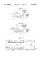
- FIG. 1shows a block diagram of an illustrative Radio Frequency Identification (RFID) system
- FIG. 2shows a block diagram of an illustrative Interrogator Unit used in the RFID system of FIG. 1;
- FIG. 3shows a block diagram of a Tag Unit used in the RFID system of FIG. 1;
- FIG. 4shows the relationships among the Interrogation Mode, Location Mode, and Messaging Mode Ranges
- FIG. 5shows the relationships among the Uplink Range for the Interrogation Mode, the Uplink Range for the Location and Messaging Modes, and the downlink Range for all three Modes;
- FIG. 6shows a mounting arrangement for an omnidirectional antenna in the ceiling of a building
- FIG. 7shows an alternate arrangement for an omnidirectional antenna in the ceiling of a building
- FIG. 8shows the relationship between the Uplink Antenna pattern and the Downlink Antenna pattern
- FIG. 9shows an arrangement for combining the inputs from two receive antennas
- FIG. 10shows an arrangement for switching between the inputs from two receive antennas
- FIG. 11shows the Frame structure of Downlink and Uplink signals
- FIG. 12shows one embodiment of how the Downlink signal could be subdivided
- FIG. 13shows one embodiment of how the Uplink signal could be subdivided
- FIG. 14shows where the Messaging Mode Uplink Response could be located
- FIG. 15shows how the Subcarrier Demodulator of FIG. 2 can support demodulation on two subcarrier channels
- FIG. 16shows how the RFID System of FIG. 1 can be interconnected to electronic mail and voice mail systems
- FIG. 17shows how the Subcarrier Demodulator of FIG. 2 can also support demodulation on an Emergency Channel.
- FIG. 1there is shown an overall block diagram of a traditional RFID system.
- An Applications Processor 101communicates over a Local Area Network (LAN, 102), which could be wired or wireless, to a plurality of Interrogators (103, 104).
- the Interrogatorsmay then each communicate with one or more of the Tags (105, 107).
- the Interrogator 103receives an information signal, typically from an Applications Processor 101.
- the Interrogator 103takes this information signal and Processor 200 properly formats a Downlink message (Information Signal 200a) to be sent to the Tag.
- Information Signal 200aInformation Signal
- Radio Signal Source 201synthesizes a radio signal
- the Modulator 202modulates this Information Signal 200a onto the radio signal
- the Transmitter 203sends this modulated signal via Antenna 204, illustratively using amplitude modulation, to a Tag.
- Antenna 204illustratively using amplitude modulation
- the reason amplitude modulation is a common choiceis that the Tag can demodulate such a signal with a single, inexpensive nonlinear device (such as a diode).
- the Antenna 301receives the modulated signal.
- This signalis demodulated, directly to baseband, using the Detector/Modulator 302, which, illustratively, could be a single Schottky diode.
- the result of the diode detectoris essentially a demodulation of the incoming signal directly to baseband.
- the Information Signal 200ais then amplified, by Amplifier 303, and synchronization recovered in Clock Recovery Circuit 304.
- the Clock Recovery Circuit 304can be enhanced by having the Interrogator send the amplitude modulated signal using Manchester encoding.
- the resulting informationis sent to a Processor 305.
- the Processor 305is typically an inexpensive 4 or 8 bit microprocessor; the Clock Recovery Circuits 304 can be implemented in an ASIC (Application Specific Integrated Circuit) which works together with or is incorporated within the integrated circuit containing Processor 305. This Processor 305 can also serve as the driver for an optional Display Unit 309 should this Tag require a display.
- the Processor 305generates an Information Signal 306 to be sent from the Tag 105 back to the Interrogator (e.g., 103). This Information Signal 306 is sent to a Modulator Control Circuit 307, which uses the Information Signal 306 to modulate a subcarrier frequency generated by the Frequency Source 308.
- the Frequency Source 308could be a crystal oscillator separate from the Processor 305, or a signal derived from the output of a crystal oscillator, or it could be a frequency source derived from signals present inside the Processor 305--such as a multiple of the fundamental clock frequency of the Processor.
- the Modulated Subcarrier Signal 311is used by Detector/Modulator 302 to modulate the modulated signal received from Tag 105 to produce a modulated backscatter (i.e., reflected signal). This is accomplished by switching on and off the Schottky diode using the Modulated Subcarrier Signal 311, thereby changing the reflectance of Antenna 301.
- a Battery 310 or other power supplyprovides power to the circuitry of Tag 105.
- MBSModulated Backscatter
- the Modulator Circuit 307 of the Taggenerates a modulated signal, which is amplitude modulated by an Information Signal 306 at frequency f 2 . If the Radio Signal Source 201 generates an unmodulated frequency f 1 , then the Interrogator receives signals inside of the range (f 1 -f 2 ) to (f 1 +f 2 ), and generally filters out signals outside of that range. This could be termed the "MBS at baseband" approach. Another approach would be for the Tag to generate two different subcarrier frequencies.
- the informationcould be conveyed in a frequency-shift keyed (FSK) fashion with the subcarrier frequency transitioning between these two frequencies.
- FSKfrequency-shift keyed
- Other modulation schemesare possible as well, such as Phase Shift Keying (PSK) of a single subcarrier frequency (e.g., BPSK, QPSK) or other complex modulation schemes (e.g., MFSK, MASK, etc.).
- the Interrogator 103receives the reflected and modulated signal with the Receive Antenna 206, amplifies the signal with a Low Noise Amplifier 207, and demodulates the signal using homodyne detection in a Quadrature Mixer 208.
- a single Transmit (204) and Receive (206) Antennais used. In this event, an electronic method of canceling the transmitted signal from that received by the receiver chain is needed; this could be accomplished by a device such as a Circulator.
- Using the same Radio Signal Source 201 as used in the transmit chainmeans the demodulation to baseband is done using Homodyne detection; this has advantages in that it greatly reduces phase noise in the receiver circuits.
- the Mixer 208then sends the Demodulated Signal 209 (if a Quadrature Mixer, it would send both I (in phase) and Q (quadrature) signals) to the Filter/Amplifier 210.
- the resulting filtered signal--which in this inventionis an Information Signal 211 carried on a subcarrier--is then demodulated from the subcarrier in the Subcarrier Demodulator 212, which then sends the Information Signal 213 to a Processor 200 to determine the content of the message.
- the I and Q channels of Signal 209can be combined in the Filter/Amplifier 210, or in the Subcarrier Demodulator 212, or they could be combined in the Processor 200.
- a short-range, bidirectional digital radio communications channelis implemented.
- a relatively inexpensive implementationis achieved using, as exemplary components, a Schottky diode, an amplifier to boost the signal strength, bit and frame synchronization circuits, an inexpensive 4 or 8 bit microprocessor, subcarrier generation circuits, and a battery. Most of these items are already manufactured in quantities of millions for other applications, and thus are not overly expensive.
- the circuits mentioned above for bit and frame synchronization and for subcarrier generationcan be implemented in custom logic surrounding the microprocessor core; thus, except for a relatively small amount of chip real estate, these functions come almost "for free.”
- a two-way digital radio communications channelcan be constructed. We desire to extend the range of this two-way digital radio communications channel as much as possible. This involves both extending the range of the Downlink and also extending the range of the Uplink.
- the Downlinkis generally an amplitude modulated signal, which is easily and inexpensively detected by a single nonlinear device, such as a microwave diode. It is important to match the impedances between the antenna and the diode to avoid gratuitous signal attenuation.
- the data rate of the Downlinkmust be limited in order to reduce the noise bandwidth of the Downlink signal.
- the Antenna (301)not only performs the tasks of receiving the RF signal, but it also filters RF signals outside of the antenna bandwidth. For example, at 2.45 GHz, allowable RF carrier frequencies are from 2.400-2.485 GHz.
- the design of the antennacovers this frequency band but filters out frequencies beyond this range.
- An ideal frequency responsewould be for the antenna sensitivity to be within 3 dB across the allowable frequency range, but to fall off rapidly beyond this range.
- the Amplifier (303)also acts as a filter in the sense that the Amplifier is designed to only pass Amplitude Modulated (AM) signals that are within a certain passband around the expected Downlink data rate, which is typically a few kilobits per second. Therefore, although the Tag is relatively simple, it has filtering capability to filter out both RF signals whose frequency is outside the Antenna bandwidth, and also to filter out AM signals whose frequency is outside of the Amplifier passband.
- This Tag designis also not greatly sensitive to RF transmissions, inside the band of the antenna, whose modulation scheme is primarily constant envelope. Thus, this design allows a robust Tag which is resistant to many potential interfering signals.
- Extending the range of the Uplinkalso involves several factors.
- the noise bandwidth of the Uplink signalmust be reduced as much as possible.
- a number of useful applicationscan be implemented even if the data rate of the Uplink signal is limited to a few bits per second. Indeed, this limitation of the data rate can be taken to the extreme in which there is no data modulated onto the single subcarrier frequency; in this case, the mere presence or absence of a signal received at this subcarrier frequency indicates an "acknowledgment" or "no acknowledgment" to a previously received message.
- the subcarrier frequencycan be relatively accurately determined.
- commercially available crystalsexist with a frequency of 32 kHz, and an accuracy of ⁇ 100 ppm.
- the frequency of this crystalis known to ⁇ 3.2 Hz.
- the Tagthus generates a subcarrier frequency, f s , of great accuracy.
- the Interrogatorreceives the reflected signal, and demodulates it as discussed above using Homodyne detection.
- the Filter Amplifier (210) and Subcarrier Demodulator (213) functioncould then be implemented, together, inside a processor such as a DSP.
- Narrowband filtering algorithmsexist in the literature which can perform digital filtering of the signal with a bandwidth of less than 10 Hz, and where the first sidelobes are depressed 60 dB. Then, the signal strength of the signal received through this digital filter is measured, and that strength is compared to a reference signal strength which is sufficiently above the average noise in that channel when no signal is present such that spurious noise spikes are not misinterpreted as actual signals.
- MBS systemsexhibit noise in the Uplink signals due to reflections of the RF source from any number of reflectors. Walls and metal objects reflect RF radiation; these reflected signals are received by the Interrogator 103 at the same carrier frequency as they were transmitted.
- the Quadrature Mixer 208is operated as a Homodyne Detector and thus is used to cancel these reflections.
- other reflectorsgenerate reflected noise at frequencies away from the main carrier frequency--either from Doppler shifts or, more likely, from reflections off of electronic equipment operating at frequencies near the Subcarrier Frequency.
- the basic features of multiple mode operationare that a) the Tag must be capable of receiving a Downlink message; b) the Tag must be told what type of Uplink message it is to transmit, whether it be an actual data message (higher bit rate mode) or a simple acknowledgment message (long range mode), based upon information received in the Downlink message; c) the Tag transmits the requested type of Uplink message; and d) the Interrogator interprets the Uplink message received in a proper manner.
- Several different types of acknowledgment messages in the long range modecan exist.
- an acknowledgment messagehas a data rate which is much less than the data rate of an actual data message (the higher bit rate mode), thus allowing filtering over a much smaller frequency band, and thus allowing greater range than the higher bit rate mode since the noise bandwidth of the received signal is lessened due to the narrowband filtering.
- an acknowledgment messagecould consist of a low bit rate data message, or it could consist of a single bit of information.
- the Tagcould generate an unmodulated subcarrier frequency which could be modulated onto the incident signal, using modulated backscatter. The Interrogator would then receive a reflected signal with a single frequency tone. Narrowband filtering techniques could then be used to reduce the noise bandwidth and determine the presence or absence of this signal.
- the Tag 105detects and assembles the bits of information sent from the Interrogator 103 into a complete Downlink message. Typically, a pattern of synchronization bits is transmitted at the beginning of the Downlink message; these bits allow the Tag to acquire bit and message synchronization; enabling the Tag to determine the beginning and the end of the Downlink message.
- the Downlink message contentswould include an Address, a Command, optionally include Data, and also include Error Detect.
- the Command or Data portion of the Downlink messagecould indicate that the Tag 105 should return a Message to the Interrogator; for example, the Tag could return stored data, such as the Tag ID, or other application-specific data. Another type of Downlink message could indicate that the Tag should send back only a single-bit acknowledgment message.
- the Processor 305 of the Tag 105determines, in response to information in the Downlink message, what type of Uplink signal to transmit: a data message or a simple acknowledgment message.
- the Tag 105may transmit either a data message or a simple acknowledgment message so that the Interrogator 103 can, relatively easily, receive and distinguish between these two different types of messages.
- Processor 305sends the Information signal to the Modulator Control 307, which modulates the signal from Subcarrier Frequency Source 308.
- Processor 305sends the Information Signal over the Information Signal Lead 306 shown in FIG. 3.
- the Information Signal Lead 306is maintained at a first logic state to indicate that no information message is to be sent.
- an unmodulated subcarrier frequency signalis outputted by Modulator Control 307.
- the Information Signal Lead 306conveys the multi-bit message to Modulator Control 307.
- This multi-bit message(information signal) is then used to modulate the subcarrier frequency using one of several possible modulation techniques, such as amplitude, phase, frequency, or code modulation.
- the Interrogator 103demodulates the subcarrier signal from the received RF signal, and then applies filtering. Given the specifics of the subcarrier frequency, a suitable filtering amplifier is utilized. Subcarrier Demodulator 212 then demodulates the subcarrier signal. The Processor 200 then performs the digital signal processing necessary to decode the information.
- the Processormay be a Digital Signal Processor (DSP); in others, a conventional Microprocessor could be used.
- DSPDigital Signal Processor
- the filtering amplifierwould be a narrowband filter. While conventional filter technologies could be used, it may be most effective to utilize the DSP mentioned above as a narrowband filter.
- the subcarrier frequency of this single toneis well known; as the Tag 105 would typically use an inexpensive crystal as the frequency source. Even with the limited accuracy of that crystal, the subcarrier frequency could be known to an accuracy of a few Hertz. Thus, very narrowband filters could be used. Since the acknowledge signal response from Tag 105 is used to extend the range of the RFID system and consequently would likely be a very faint signal, it places an additional burden on the narrowband filter of filtering amplifier 210.
- Another way that the DSP mentioned above could be usedis to dynamically search for the frequency components of the Uplink signal. This could be accomplished by performing a Fourier Transform on the incoming data stream, perhaps using a DSP, or using Processor 200 of FIG. 2. In this manner, the multiple signals representing a modulated subcarrier signal could be differentiated; or, a single subcarrier signal of uncertain data rate could be recovered by using the Fourier Transform to search for multiple signals.
- a modulated backscatter communication systemcan operate in two modes--one in which the backscattered signal is modulated to provide a high data rate Uplink communication channel, and one in which the backscattered channel is modulated with a low data rate signal, perhaps a single tone, to provide an Uplink acknowledgment signal that can be detected at great distances.
- the Interrogation Modebegins with the Interrogator transmitting an Interrogation Signal to the Tag.
- the Tagreceives this Interrogation Signal, decodes it, and determines what actions to take based upon the decoded Interrogation Signal.
- the Tagwould be requested to transmit a particular set of data (called here the Mandatory Data) back to the Interrogator, using the MBS technique discussed above.
- Each Tag in the reading field of the Interrogator that receives the "standard” Interrogationresponds with its Mandatory Data, using a protocol discussed below.
- the Interrogatoralso transmits, as part of the "standard” Interrogation Signal, data intended for each and all Tags. Examples of such data include time of day, framing and other synchronization information, etc.
- the Interrogatorafter identifying a specific Tag using the Interrogation Mode, could transmit additional data to that Tag to be stored in the Tag's memory.
- the Interrogatorcould also request the Tag transmit other data, stored in the Tag's memory, back to the Interrogator.
- These additional data communicationscould be performed at the same data rate used in the "standard” Interrogation.
- the Interrogation Modeis used to: transmit commands and data to each and every Tag, identify a specific Tag in the reading field, and also used to communicate in a bidirectional manner with that specific Tag.
- the data rate required in the Downlinkis typically not large, since the Interrogation Signal only must contain enough bits to request all Tags in the reading field to respond. Even when significant amounts of Downlink data are transmitted, in many applications this process does not take place frequently and the Downlink data rate is not critical.
- the data rateis typically much larger than the Downlink data rate, as the Mandatory Data must frequently be transmitted in the Uplink in a time critical manner. Therefore, in the Interrogation Mode, we have an asymmetry in required data rates in the sense that the Downlink data rate is smaller than the Uplink data rate.
- the Interrogatortransmits an Interrogation Signal to the Tag containing the address of a specific Tag to which this Interrogation Request is directed.
- the Tagis not requested to respond with the Mandatory Data discussed above. Instead, at least in some embodiments, the requested response is a simple acknowledgment.
- a simple acknowledgmentis a constant-tone signal. Using the narrowband techniques discussed above, a constant-tone signal can be received by the Interrogator at a range far beyond the range of the Interrogation Mode. Therefore, in the Location Mode, we have an asymmetric communications path which has greater data rate in the Downlink than in the Uplink.
- each Interrogatorcan determine the signal strength of the received signal (if any), and those signal strengths can be reported to a central control element.
- the determination of locationcan be done in several ways. The most obvious way is for the control element to determine which Interrogator received the strongest signal strength. Then, the location of the Tag is equal to the location of that Interrogator, to an accuracy of the effective range of that Interrogator. A more complex method could be implemented if more than one Interrogator received a return signal.
- the Interrogation Signalnot only contains the address of a Tag or Tags, but it also may contain data intended for that Tag or Tags.
- the Tag or Tags whose address matches the Tag address in the Interrogation Signalcould be requested to store that data in the Tag's memory, or perform some other function with that data.
- the command within the Interrogation Signalrequests the Tag to make a decision, or to transmit other data back to the Interrogator, then the response would be a message consisting of more than a few bits of information. Therefore, in the Messaging Mode, we again have an asymmetric communications path which has greater data rate in the Downlink than in the Uplink.
- the Uplink data rateis limited to that data rate normally used in the Uplink for the Messaging Mode. If the signal strength is above a certain threshold, then the radio communications path between the Interrogator and this Tag can support communications at the data rate normally used in the Uplink for the Interrogation Mode. If the signal strength is below the threshold, then either data communications can continue, but using the (lower) Uplink data rate of the Messaging Mode, or a messaging could be transmitted to the Tag requesting that the Tag be brought into close proximity to an Interrogator (how that request is received by a human being is described in the above-cited Shober-Pager application. If the signal strength is above the threshold, then data communications can continue; but using the Interrogation Mode, as discussed above. It should be obvious that, while the above example shows how the Uplink communications could take place at either one of two possible Uplink data rates, it would be possible to extend the above concept to support more than two Uplink data rates.
- the Interrogation Modeinvolves significant data transmission over (relatively) short time periods, such as when an individual walks by an Interrogator.
- the required data rateis further increased, since there can be several individuals in the reading field at one time.
- a protocolsuch as Aloha or Slotted Aloha
- Examples of data rate for communication from the Tag to the Interrogator for the Interrogation Moderange from 50 kbps-300 kbps.
- FIG. 5shows the relationship between the ranges for these three Modes of operation.
- the Downlink rangeis the same for all three Modes (503).
- the Uplink range for the Location and Messaging Modes (502)is roughly the same as the Downlink range (503).
- the Uplink range for the Interrogation Mode (501)is much smaller.
- the Interrogators (103)are interconnected by a LAN, which could be wired or wireless, to one or more Application Processors (101).
- the Interrogatorsare distributed throughout the building.
- one techniquewould be to emplace enough Interrogators to put any point in the building within the radio coverage areas of at least three Interrogators. Then, to implement the Location Mode, a triangulation technique could be used, based upon the received signal strength of the Uplink signal. Although this technique is frequency used today for outdoor location services, for an in-building system this might be viewed as overly costly, because relatively many Interrogators would be required. Also, in-building radio propagation tends to be dominated by multipath; thus the triangulation technique is not very accurate.
- Interrogatorsare placed in a "partially overlapping" fashion, such that any point in the building is within the radio coverage area of at least one Interrogator. Given this configuration, a relatively simple Location Mode can be implemented, with the accuracy of the Location Mode comparable to the coverage area of one Interrogator.
- the most common antenna configuration to support the above scenariois for the Downlink transmit and the Uplink receive antennas to both be generally omnidirectional.
- an antennacould be a one quarter wavelength monopole extending downward from a round ground plane (such as a piece of metal); such an antenna could be mounted in the ceiling, and the antenna pattern would be generally omnidirectional but with most of the antenna pattern in the volume of space below the ground plane.
- FIG. 6shows such a configuration.
- the Antenna (605)is encased in a Radome (606), or plastic covering, to protect the antenna from damage and to improve aesthetics.
- FIG. 7An alternative configuration is shown in FIG. 7, where the building has a Drop Ceiling (702). Since most Drop Ceilings do not absorb much RF radiation, it is possible to locate the Ground Plane (704) above the Drop Ceiling with the Radome protruding down through the Drop Ceiling. Then, the only portion of the antenna that is visible is the Radome, which may be as few as 2-3 inches across, or even less. Thus, this design allows the antennas to be very inconspicuous.
- the antenna configuration presented in FIGS. 7 and 8will be referred to as the "omnidirectional" antenna configuration.
- the "omnidirectional" antenna patternis useful for both the Downlink and the Uplink messages.
- a directional antennait is common for a directional antenna to be used to define a specific volume of space within which the Interrogation Mode is available.
- FIG. 8shows one concept of how differing antenna patterns could be used to support the Interrogation Mode.
- the Downlink (or transmit) Antenna (801)could be omnidirectional; while the Uplink (or receive) Antenna (802) could be directional.
- the Downlink Antenna (801) from this Interrogatorcould transmit Downlink Signals for any of the three Modes of operation; while the Uplink Antenna (802) (in the directional configuration) could receive the Uplink signal from the Tag operating in the Interrogation Mode.
- FIGS. 9 and 10illustrate two ways that different receive antennas can be used.
- FIG. 9shows that the outputs of the Omnidirectional Receive Antenna (902) and the Directional Receive Antenna (903) are combined in a linear manner.
- This techniquehas the advantage of the system being simple and inexpensive, and capable of receiving Uplink signals from either antenna. However, it has the advantage of at least 3 dB of loss if the signal is coming from only one of the antennas.
- FIG. 10shows a simple switch mechanism to use a Switch (1002) to switch from the Omnidirectional Receive Antenna (1003) to the Directional Receive Antenna (1004). This has advantage of eliminating the 3 dB loss (assuming the switch has negligible loss), and the disadvantage of a more complex and costly Interrogator design.
- the Signal Strength (214) signalwhich in this embodiment is an output of the Subcarrier Demodulator (212), can be used by the Processor (200) to determine if adequate signal to noise exists to support the higher Uplink data rate required by the Interrogation Mode.
- the Signal Strength (214) indicatorcould also be an output of the Filter Amplifier (210) or could even be taken from the Output (209) of the Mixer (208).
- a transitioncould be from the Location Mode to the Interrogation Mode.
- a Location Mode Interrogation Signalcould be transmitted by the Interrogator, and the Signal Strength (214) indicator could be used to determine whether adequate signal-to-noise ratio exists to support the higher Uplink data rate required by the Interrogation Mode.
- the Uplink error rate(as determined by the Processor (200) which calculates an error detection code for each Uplink message) indicates that the signal to noise ratio is not great enough to support the Interrogation Mode Uplink data rate. Then, data communications can continue, but at a greatly reduced Uplink data rate, using the Messaging Mode.
- FIG. 11shows a general outline of the frame structure; two Frames, Frame A and Frame B, are shown.
- Frame A (1110)the Interrogator communicates with the Tag during Downlink D A (1101); at the completion of Downlink D A , the Tag communicates with the Interrogator during Uplink U A (1103).
- Frame Bconsists of Downlink D B (1102) and then Uplink U B (1104).
- FIG. 12illustrates how Downlink D A (1101) could be structure
- a series of Sync (1210) bitscould be sent; this would enable the Tag to synchronize to the timing of the Interrogator.
- a Command (1220) bit fieldcould be sent; this command would instruct the Tag as to which Mode of operation is being requested.
- a Data Message (1240)would be sent; this Data Message would contain data for each and every Tag, such as clock data, frame synchronization information, etc.
- the last fieldwould be the Error Detect (1250) field; this would provide error detection for the Downlink message, and depending on the number of bits transmitted, could also provide some measure of error correction.
- the Sync (1210) and Command (1220) fieldscould be combined, and an explicit Error Detect (1250) field may not be required.
- a specific Tagis being addressed; thus an additional field, namely a Tag Address (1230) field, is required. This field is used by the Tags to determine which specific Tag is being addressed.
- a Tag Address (1230) fieldis required. This field is used by the Tags to determine which specific Tag is being addressed.
- the Messaging Modeall of the fields shown in FIG. 12 could be present.
- FIG. 13illustrates how the Uplink U A (1103) could be structured.
- the Uplink U Acould be divided, for example, into eight "Slots".
- the three Modes of operation(Interrogation, Messaging, and Location) share the eight slots.
- This sharingcan be done in several ways.
- the simplest method of sharingis pure time division multiplexing. In this method, the Interrogator first transmits Downlink D A (1101). This message instructs the Tags (105), for example, to respond in the "standard" Interrogation Mode. In this mode, the Tags transmit their uplink information multiple times in randomly chosen time slots.
- FIG. 13shows a Tag transmitting uplink information UI1 (1311) during Slot 2 (1302) and UI2 (1312) during Slot 6 (1306). This method allows multiple Tags to respond with their uplink information during the same Frame or set of Frames.
- the Interrogatortransmits Downlink D A (1101), whose Command (1220) field instructs the Tags that the Messaging Mode is desired, and also instructs all Tags to continue listening to Downlink D A (1101) SO that each can determine whether its address matches that contained in the Tag Address (1230) field to be transmitted next.
- the Tagwhose address is present in the Tag Address (1230) field then responds by transmitting an uplink message.
- message UM1(1313) is shown being transmitted in all eight Slots. The reason that all eight slots might be needed is to improve the signal-to-noise ratio of this Uplink signal such that the Uplink range in the Messaging Mode is comparable to the Downlink range.
- the Interrogatortransmits Downlink D A (1101), whose Command (1220) field instructs the Tags that the Location Mode is desired, and also instructs all Tags to continue listening to Downlink D A (1101) so that each can determine whether its address matches that contained in the Tag Address (1230) field to be transmitted next.
- the Tagwhose address is present in the Tag Address (1230) field then responds by transmitting an uplink message.
- message UL1(1314) is shown being transmitted in all eight slots. This Uplink message uses all eight slots for the same reason as discussed above for the Messaging Mode.
- Interrogation Mode messagessuch as UI1 and UI2 can share Uplink U A (1103) by transmitting in different Slots.
- the Interrogatormay wish to receive data from a specific Tag at the Interrogation Mode Uplink data rate. This could be done in several ways.
- the Interrogatorcould transmit an Interrogation Signal to all Tags, as done in the "standard" Interrogation Mode, which contains a specific Tag Address (1230). This Interrogation Signal instructs this specific Tag to respond with specific data, the identity of the requested data specified in the Data Message (1240) field, and to use the Uplink slot mechanism shown in FIG. 13; i.e., to transmit the required data in only a subset of the available Slots.
- Interrogation Mode signalcould respond with their Mandatory Data in other of the available Slots, or the Interrogation Signal could instruct those other Tags to remain silent.
- the Interrogation Signalinstructs a specific Tag to transmit the requested data in all of the Slots shown in FIG. 13, and also instructs all other Tags in range of the Interrogation Signal to be silent until another Interrogation Signal, with different instructions, is received.
- each Interrogatorcommunicates with the Application Processor via a wired or wireless LAN.
- the LANprovides both timing information and data transfer to and from the Interrogators.
- UplinkThere are alternative embodiments for the Uplink.
- all Interrogators within each Domainare operating in the same Mode for each Uplink Signal (e.g., 1103).
- This embodimentis called Time Division Multiple Access (TDMA), because we are time-sharing the Uplink Signal (1103) time period among three Modes of operation.
- TDMATime Division Multiple Access
- the Interrogation Modecan proceed simultaneously with the other two Modes; thus, the Location and Messaging Modes use TDMA to share the Uplink Signal (1103) time period.
- the Interrogation Mode and the other two Modescan share the Uplink Signal (1103) time period through the use of Frequency Division Multiple Access (FDMA).
- FDMAFrequency Division Multiple Access
- the Frequency Source for the Subcarrier (308)is typically a crystal which is also used to provide the clock reference for the Processor. In the "Narrowband Operation" section above, the Frequency Source (308) was a 32 kHz crystal, chosen for its low cost, and the Subcarrier frequency was derived from the 32 kHz signal.
- the Modulator Control (307)could support the generation of more than one Subcarrier frequency.
- the Tagcould be instructed, based upon the information in the Command (1220) of the Downlink Signal, as to which of (potentially several) Subcarrier frequencies to use to transmit their Uplink Signals. In this manner, more than one Tag could be transmitting an Uplink signal at the same time, since the Interrogator could decode (see below) Uplink signals on multiple Subcarrier frequencies at the same time.
- FDMAas outlined above, one Tag could be responding to an Interrogation Mode signal, and at the same time another Tag could be responding to a Location Mode signal on another Subcarrier frequency.
- the placement of the Subcarrier frequencies to allow an inexpensive Tag and Interrogator designis discussed below. We should note that the use of 32 kHz as a crystal frequency is just one example of potential crystal frequencies.
- the Modulator Control (307)When the Tag wishes to respond to a Location Mode signal, the Modulator Control (307) generates a subcarrier frequency f s .
- the subcarrier frequency signalis not modulated with data, and that signal is used to apply alternating states of bias current to the Detector/Modulator (302) diode, thus changing the impedance match between the Antenna and the diode at the Subcarrier frequency f s .
- the Interrogatoris transmitting a pure CW tone of frequency f c .
- the Detector/Modulator diode (302)is alternately reverse and forward biased at the frequency f s , then the reflected signal is at frequencies (f c -f s ) and (f c +f s ) (overtones of this mixing process are ignored).
- the results of the Subcarrier Demodulator (212)are a single tone at frequency f s . The presence or absence of this Subcarrier frequency is then used to determine whether an acknowledgment is received.
- the Modulator Control (307)generates a subcarrier frequency f s , and then modulates data, at a very low bit rate, onto that subcarrier.
- the resultant modulated subcarrier signalis used to apply alternating states of bias current to the Detector/Modulator (302) diode, thus changing the impedance match between the Antenna and the diode such that a reflected signal, at the Subcarrier frequency f s , modulated with data, is generated.
- This latter embodimentcould be used for the Tag to transmit information pertaining to its status in addition to simply transmitting a constant tone. In both cases, the signal strength of the received signal could be used to determine the location of the Tag.
- an Information Signalis modulated onto the Subcarrier frequency f s .
- This modulationcould be done using a number of techniques; however, for purposes of this discussion, we assume that either BPSK or QPSK modulation is used.
- the results of the Subcarrier Demodulator (212)are a BPSK or QPSK signal modulated onto a carrier of frequency f s .
- the BPSK or QPSK signalis then demodulated from the Subcarrier f s to recover the Information Signal (211).
- the Information Signal (211)has a bit rate of 50 kbps-300 kbps; while for the Messaging Mode, a much lower bit rate (discussed below) is used.
- the circuitry in the Modulator Control (307) to implement the capability of modulating different Information Signal data rates onto the Subcarrier frequency f scan be simple in design.
- the reflected signalis received by the Receive Antenna (206), and amplified by the Low Noise Amplifier (207).
- the Mixer (208)then performs the homodyne detection.
- the Mixer (208)should produce both I (in phase) and Q (quadrature) components of the demodulated signal.
- these signalscan be re-combined at several different points in the system.
- the exact place and technique for this re-combinationis not critical. Therefore, we assume the Filter Amplifier (210) re-combines these signals before the filtering process, using any one of a number of conventional combination techniques.
- the subcarriermust be selected with multiple criteria in mind. As discussed above, MBS systems must contend with "reflection noise", i.e., RF signals transmitted by the Interrogator that are reflected from objects in the RF field. Some objects, such as fluorescent lights, both modulate and reflect RF signals at overtones of the AC line frequency. Therefore, the subcarrier should be chosen to avoid as much of the reflection noise as possible.
- the second factor to consideris the ease of generating the Subcarrier frequency in the Tag. Crystals are available at multiples of one megahertz, and also at "odd" frequencies, such as 3.5795 MHz, which are widely available as they are used in color television sets. Let us assume that a crystal of 8 MHz is chosen; then, circuitry to count down the 8 MHz to a Subcarrier frequency f s of 1 or 2 MHz is straightforward.
- the Subcarrier frequencyshould not be chosen too large, for two reasons. First, crystals generally are more expensive at larger frequencies. Second, the demodulation of the information signal from the Subcarrier will be made more complex the higher the Subcarrier frequency; e.g., if the Subcarrier signal is sampled, the required sampling rate is proportional to the Subcarrier frequency. Thus, a high Subcarrier frequency will require more costly analog to digital converters, and (for example) a more powerful digital signal processor to process those sample. We believe a Subcarrier frequency greater than 100 kHz and less than 2 MHz is a good compromise.
- the same Subcarrier frequency f sis then used for all three Modes of operation.
- the Filter Amplifier (210) in FIG. 2can be centered on the same frequency for all three Modes.
- the bandwidth of the Filter Amplifier (210)would be designed to be wide enough to pass the greatest bandwidth signal, which is the Uplink Signal from the Interrogation Mode. For example, assume an Uplink Signal of 100 kbps using QPSK Modulation; then the signal bandwidth is 100 kHz.
- the filtered Uplink Signalis then sent to the Subcarrier Demodulator (212).
- the (for example) QPSK information signalis demodulated from the Subcarrier frequency using conventional techniques.
- the bandwidth of the information signal in the Interrogation Modeis (for example) 100 kHz.
- the bandwidth of the Uplink Signal for the Messaging Modeis (for example) 100 kHz.
- each "Frame"is of a time duration such that the Uplink portion of the frame, such as U A (1203), is about 100 ms in duration.
- the effective bit rateis 40 bps; using (for example) QPSK modulation, the signal bandwidth is 40 Hz.
- the output of the Filter Amplifier (210)is 2,500 times greater than that required for the Messaging Mode; or, in other words, the noise bandwidth of the incoming signal for the Messaging Mode (100 kHz) is 34 dB greater than the 40 Hz necessary here, causing the effective range of the Messaging Mode to be greatly reduced.
- the narrowband techniques discussed abovecan be used.
- the Uplink Signalis a constant tone.
- the effective "data rate”is 10 bps
- the occupied signal bandwidth(in the absence of Doppler shifts) is 10 Hz.
- the noise bandwidth of the signal coming from the Filter Amplifier (210)(100 kHz) is 40 dB greater than the 10 Hz required here, leading to a large decrease in range.
- narrowband filtering techniquesmust be used to decrease the noise bandwidth and recover the required range for the Location Mode.
- a DSPis advantageously used as the Subcarrier Demodulator (212); this would be convenient because we require the received signal strength for both the Location and the Messaging Modes. If a DSP is used, then analog-to-digital converters are also required; however these are not explicitly shown in FIG. 2.
- the Filter Amplifier (210)would initially filter the received signal at a bandwidth of, e.g., 100 kHz, sufficient for the Interrogation Mode Signal (1407, see FIG. 14).
- the Subcarrier Demodulatorcould be implemented as a DSP, or as a combination of a special purpose Application Specific Integrated Circuit (ASIC) and a DSP.
- the special purpose ASICcould be used to demodulate the Interrogation Mode Signal (1407), since no additional filtering would be required.
- a DSPwould likely be required, since additional narrowband filtering is required to reduce the noise bandwidth to either 40 Hz or 10 Hz.
- a DSPcould be programmed in a straightforward manner to implement one or the other of these two filter bandwidths. In the event that data must be demodulated from this subcarrier signal, the DSP could implement that demodulation in a straightforward manner using known techniques. Alternately, the DSP could perform all of the above functions, but only one at a time. The demodulation of the Interrogation Mode Signal would be straightforward for the DSP, and no additional filtering would be required. The DSP could also perform additional digital filtering and (if necessary) demodulation as discussed above for the Messaging and Location Modes.
- one Subcarrier frequency f s1is used for the Interrogation Mode, and another Subcarrier frequency f s2 is used for the Messaging and Location Modes, as shown in FIG. 14.
- the Filter Amplifier (210) in FIG. 2could be designed to pass both of the signals shown in FIG. 14.
- the Subcarrier Demodulator (212)then must be capable of processing both Uplink signals simultaneously. Let us assume, as above, that the Signal Bandwidth--Interrogation Mode (1403) is 100 kHz, and is located at Subcarrier frequency f s1 (1401). Let us also assume, as above, that the Signal Bandwidth--Messaging Mode (1404) is 40 Hz, centered at Subcarrier frequency f s2 (1402).
- FIG. 15shows a possible embodiment of the Subcarrier Demodulator to implement FDMA.
- a Filter f s1(1501) is designed such that its response is centered around Subcarrier frequency f s1 , and this filter is used in conjunction with a High Data Rate Demodulator (1503) to recover the High Data Rate Signal (1505), which is the Uplink Signal from the Interrogation Mode (1407).
- a Filter f s2(1502) is designed such that its response is centered around a Subcarrier frequency f s2 , and this filter is used in conjunction with a Low Data Rate Demodulation (1504) to recover the Low Data Rate Signal (1506), which is the Uplink Signal from the Messaging or Location Mode (1406). Since the bandwidth of the Messaging and the Location Modes are relatively similar, we assume that the same device, a Low Data Rate Demodulator (1504), can be used to demodulate each signal.
- Subcarrier frequency f s2could be as follows. Assume that Filter f s1 is a matched filter (sin x/x). Assume the Subcarrier frequency f s2 is located at the first zero of this filter (see Matched Filter Response (1505)). With this location of f s2 , the presence of the Messaging or Location uplink signal is heavily filtered by Filter f s1 (1501), and thus that signal is unlikely to interfere with the High Data Rate Demodulator (1503). The Interrogation Mode Uplink Signal, centered at Subcarrier frequency f s2 , is unlikely to interfere with the Messaging or Location uplink signal since the Filter f s2 is very narrowband.
- the Subcarrier Demodulator (212)could be implemented in a DSP, assuming the DSP was powerful enough to process all of the functions of FIG. 15 in real time.
- the use of a DSPwould also be convenient as we require the received signal strength for both the Location and the Messaging Modes. If a DSP is used, then analog to digital converters are also required; however these are not explicitly shown in FIG. 2 or in FIG. 15.
- a DSPcould be used to implement both the Filter f s2 (1502) and the Low Data Rate Demodulator (1504); this embodiment was outlined above in the TDMA discussion.
- the Low Data Rate Demodulator (1504)must also output the Signal Strength (1507) of the received signal, for the purpose of providing that information to a central control element so that a Tag's location can be determined.
- FIG. 16shows how the RFID system of FIG. 1 can be interconnected to other in-building communications systems.
- a Voice Mail System (1610)can communicate with the Applications Processor (101) over the LAN (102); in addition, an Electronic Mail System (1630) can also communicate with the Applications Processor (101) over the LAN (102).
- Alternate embodimentssupport the Voice Mail System (1610) and/or the Electronic Mail System (1630) being directly connected to the Applications Processor (101) rather than being connected by the LAN (102).
- FIG. 16makes the Applications Processor (101) appear to be a separate element, it could be implemented as part of one, or more than one, of the Interrogators (103).
- a message, addressed to Person 1is received by the Voice Mail System (1610).
- the Voice Mail Systemdetermines that this is an important message, and therefore a message should be transmitted to the Tag being carried by Person 1.
- the Voice Mail System (1610)could determine the importance of this message in several ways. For example, it could prompt the individual calling Person 1 with the question as to whether this voice message is of sufficient importance that Person 1 should be immediately informed of the message's arrival. Another method to determine importance is for the Voice Mail System (1610) to "filter" incoming messages according to pre-set criteria. Let us say that Person 1 always wants to be informed of a message from Person 2.
- Person 1then requests the Voice Mail System (1610) to automatically inform Person 1 whenever a phone call comes in from the phone number of Person 2 (this could be done by using incoming number identification).
- a Signal (1620)is sent to the Applications Processor (101) of the RFID System of FIG. 1.
- the Applications Processorthen instructs all Interrogators, or perhaps all Interrogators in a particular Domain, to transmit a Messaging Mode Signal, informing the Tag (105) attached to Person 1 that an important message has arrived, perhaps including the name of Person 1 and/or the phone number of Person 1, and requesting a response from the Tag.
- the Electronic Mail Systemcan be programmed to support a list of incoming electronic mail addresses, in which if a message is received from any of those addresses, Person 1 is immediately notified.
- the Electronic Mail System (1630)could transmit a Signal (1640) to the Applications Processor (101) in an identical manner to that described above. As above, the response could be transmitted back to the Electronic Mail System (1630) over route 1640. Not only could the fact that an incoming electronic mail message was received be transmitted to the Tag, but also some or all of the text of the message (depending on the amount of the text and the amount of data storage on the Tag).
- the Tag (105)could also transmit a response message back to the Electronic Mail System (1630); the mechanism for how the Tag can interact with Person 1 is discussed in the Shober-Pager patent application cited above.
- the Interrogator (103)transmits to the Applications Processor (101) a message containing at least the identification number of the Tag, the location of the Interrogator (103) which successfully communicated with the Tag, and the time of day. This information is stored in the Location Database (1650).
- the Voice Mail System (1610), or the Electronic Mail System (1630), or Another System (1660)desires to locate Person 1.
- the first thing for the Applications Processor to dois to check the Location Database (1650) to determine if a recent location is on file for Person 1. If the location is recent enough, the information in the Location Database (1650) may be adequate. The information in the database may be helpful in narrowing down where in the building Person 1 is currently located; thus, for example, the Applications Processor (101) could instruct only those Interrogators (103) in the Domain where the Tag (105) was last detected to transmit Location Mode signals.
- the location system outlined abovecan be useful to locate Tags attached to humans, as well as Tags attached to animals or to items in inventory.
- the above techniquesapply equally well to general inventory management applications.
- the Tag (105)is always in Downlink range, and therefore always in Uplink range for the Messaging Mode.
- the Tagwhen receiving a Messaging Mode transmission, could respond with an Uplink Signal of a specific bit pattern that would be identified by the Subcarrier Demodulator (212) of the Interrogator (103).
- the Tagcould respond to the Messaging Mode transmission, but it could transmit the Messaging Mode Uplink on a different subcarrier frequency f s than normally used; this could be the "emergency channel.”
- an additional set of devicesFinter f 2 (1502) and Low Data Rate Demodulator (1504)
- the Filter f s 3 (1710) and the Emergency Channel Demodulator (1720)are always tuned to the subcarrier frequency of the "emergency channel.” Therefore, the Tag (105) could always be able to inform the Applications Processor (101) of unusual operations, etc.
Landscapes
- Engineering & Computer Science (AREA)
- Physics & Mathematics (AREA)
- Remote Sensing (AREA)
- General Physics & Mathematics (AREA)
- Radar, Positioning & Navigation (AREA)
- Computer Networks & Wireless Communication (AREA)
- Artificial Intelligence (AREA)
- Health & Medical Sciences (AREA)
- Toxicology (AREA)
- Theoretical Computer Science (AREA)
- Computer Vision & Pattern Recognition (AREA)
- Electromagnetism (AREA)
- General Health & Medical Sciences (AREA)
- Signal Processing (AREA)
- Radar Systems Or Details Thereof (AREA)
- Mobile Radio Communication Systems (AREA)
- Near-Field Transmission Systems (AREA)
Abstract
Description
Claims (38)
Priority Applications (9)
| Application Number | Priority Date | Filing Date | Title |
|---|---|---|---|
| US08/775,701US5952922A (en) | 1996-12-31 | 1996-12-31 | In-building modulated backscatter system |
| CA002219074ACA2219074C (en) | 1996-12-31 | 1997-10-27 | In-building modulated backscatter system |
| EP05027281AEP1643268B1 (en) | 1996-12-31 | 1997-12-16 | In-building modulated backscatter system |
| DE69739814TDE69739814D1 (en) | 1996-12-31 | 1997-12-16 | Modulated backscatter system in a building |
| DE69735471TDE69735471T2 (en) | 1996-12-31 | 1997-12-16 | Radio communication system with location of labels |
| EP97310183AEP0851239B1 (en) | 1996-12-31 | 1997-12-16 | Radio communication system with tag location facility |
| KR1019970078536AKR100397688B1 (en) | 1996-12-31 | 1997-12-30 | Communication system and interrogator |
| JP01213898AJP3484336B2 (en) | 1996-12-31 | 1998-01-05 | Communications system |
| JP2002261960AJP3905443B2 (en) | 1996-12-31 | 2002-09-06 | Communication system and interrogator |
Applications Claiming Priority (1)
| Application Number | Priority Date | Filing Date | Title |
|---|---|---|---|
| US08/775,701US5952922A (en) | 1996-12-31 | 1996-12-31 | In-building modulated backscatter system |
Publications (1)
| Publication Number | Publication Date |
|---|---|
| US5952922Atrue US5952922A (en) | 1999-09-14 |
Family
ID=25105219
Family Applications (1)
| Application Number | Title | Priority Date | Filing Date |
|---|---|---|---|
| US08/775,701Expired - LifetimeUS5952922A (en) | 1996-12-31 | 1996-12-31 | In-building modulated backscatter system |
Country Status (6)
| Country | Link |
|---|---|
| US (1) | US5952922A (en) |
| EP (2) | EP0851239B1 (en) |
| JP (2) | JP3484336B2 (en) |
| KR (1) | KR100397688B1 (en) |
| CA (1) | CA2219074C (en) |
| DE (2) | DE69739814D1 (en) |
Cited By (172)
| Publication number | Priority date | Publication date | Assignee | Title |
|---|---|---|---|---|
| US6046683A (en)* | 1996-12-31 | 2000-04-04 | Lucent Technologies Inc. | Modulated backscatter location system |
| US6134692A (en)* | 1997-03-21 | 2000-10-17 | Kabushiki Kaisha Toshiba | Information identification system for identifying response units by a control unit, and the control unit and the response units for the information identification system |
| US6175550B1 (en)* | 1997-04-01 | 2001-01-16 | Lucent Technologies, Inc. | Orthogonal frequency division multiplexing system with dynamically scalable operating parameters and method thereof |
| US6192222B1 (en)* | 1998-09-03 | 2001-02-20 | Micron Technology, Inc. | Backscatter communication systems, interrogators, methods of communicating in a backscatter system, and backscatter communication methods |
| US20010001553A1 (en)* | 1999-02-10 | 2001-05-24 | Scott Hahn | Communications system and method with A/D converter |
| US6275476B1 (en)* | 1998-02-19 | 2001-08-14 | Micron Technology, Inc. | Method of addressing messages and communications system |
| US6326889B1 (en) | 1999-07-29 | 2001-12-04 | Micron Technology, Inc. | Radio frequency identification device and methods of determining a communication range of an interrogator of a wireless identification system |
| US20020011932A1 (en)* | 1998-06-02 | 2002-01-31 | Rf Code, Inc. | Object identification system with adaptive transceivers and methods of operation |
| US20020015436A1 (en)* | 1998-04-24 | 2002-02-07 | Ovard David K. | Modulators, transmitters, a radio frequency identification device system and carrier signal suppression methods |
| US20020014993A1 (en)* | 2000-06-19 | 2002-02-07 | Turner Christopher Gordon Gervase | Broad bandwidth, high impedance transponder for electronic identification system |
| US6346884B1 (en)* | 1998-09-25 | 2002-02-12 | Mitsubishi Materials Corporation | Apparatus for identifying an article |
| US6351215B2 (en) | 1998-06-02 | 2002-02-26 | Rf Code, Inc. | Monitoring antenna system |
| US6369710B1 (en) | 2000-03-27 | 2002-04-09 | Lucent Technologies Inc. | Wireless security system |
| US20020063622A1 (en)* | 2000-11-29 | 2002-05-30 | Ludwig Kipp | Method and system for communicating with and tracking RFID transponders |
| US20020090958A1 (en)* | 1999-03-09 | 2002-07-11 | Ovard David K. | Wireless communication systems, interrogators and methods of communication within a wireless communication system |
| US6420994B1 (en)* | 1998-06-15 | 2002-07-16 | Vantageport, Inc. | Volume in space locator |
| US6456668B1 (en) | 1996-12-31 | 2002-09-24 | Lucent Technologies Inc. | QPSK modulated backscatter system |
| US6459376B2 (en) | 1999-07-29 | 2002-10-01 | Micron Technology, Inc. | Radio frequency identification devices, remote communication devices, wireless communication systems, and methods of indicating operation |
| WO2002077940A1 (en)* | 2001-03-26 | 2002-10-03 | Sensormatic Electronics Corporation | Digital detection filters for electronic article surveillance |
| US20020145036A1 (en)* | 2001-04-04 | 2002-10-10 | Otto Jerome A. | Radio frequency identification system and method |
| US6507607B1 (en)* | 1997-01-30 | 2003-01-14 | Motorola, Inc. | Apparatus and method for recovering a clock signal for use in a portable data carrier |
| US20030020595A1 (en)* | 2001-07-12 | 2003-01-30 | Philips Electronics North America Corp. | System and method for configuration of wireless networks using position information |
| US6567002B2 (en)* | 2000-09-08 | 2003-05-20 | Alessandro Manneschi | Transponder reading transducer to control passages |
| US6600443B2 (en) | 2000-06-05 | 2003-07-29 | Tc (Bermuda) License, Ltd. | Method and apparatus to determine the direction to a transponder in a modulated backscatter communication system |
| US20030212597A1 (en)* | 2002-05-10 | 2003-11-13 | Igt | Multi-level point accumulation for a player tracking system and method |
| US20040027240A1 (en)* | 1999-03-09 | 2004-02-12 | Roy Greeff | Interrogators, methods of operating a coherent interrogator, backscatter communication methods, interrogation methods, and signal processing methods |
| US20040038677A1 (en)* | 1999-08-05 | 2004-02-26 | Avery David M. | Location finding system and method |
| US6717516B2 (en)* | 2001-03-08 | 2004-04-06 | Symbol Technologies, Inc. | Hybrid bluetooth/RFID based real time location tracking |
| WO2004029651A1 (en)* | 2002-09-27 | 2004-04-08 | Tagsys Australia Pty Ltd | Method and apparatus for maintaining pseudo-synchronism in rfid tags |
| US20040066752A1 (en)* | 2002-10-02 | 2004-04-08 | Hughes Michael A. | Radio frequency indentification device communications systems, wireless communication devices, wireless communication systems, backscatter communication methods, radio frequency identification device communication methods and a radio frequency identification device |
| US20040097252A1 (en)* | 2002-09-24 | 2004-05-20 | Serge Hethuin | Method and device of non-selective identification for combat or action group |
| US6781544B2 (en)* | 2002-03-04 | 2004-08-24 | Cisco Technology, Inc. | Diversity antenna for UNII access point |
| US20040189476A1 (en)* | 2003-03-24 | 2004-09-30 | Borovoy Richard D. | Apparatus and method for enhancing face-to-face communication |
| US20040198222A1 (en)* | 2002-10-02 | 2004-10-07 | Emre Ertin | Method of simultaneously reading multiple radio frequency tags, RF tags, and RF reader |
| US20040203361A1 (en)* | 2000-03-27 | 2004-10-14 | Wherenet Corp | Use of rotating magnetic field to enhance communication with rf burst-transmitting tags of object location system |
| US20040212480A1 (en)* | 2003-04-28 | 2004-10-28 | Battelle Memorial Institute | System and method for inventorying multiple remote objects |
| US20040222889A1 (en)* | 2003-03-14 | 2004-11-11 | Masaki Hoshina | Contactless data communication system, contactless identification tag and contactless identification tag control program |
| US6838989B1 (en)* | 1999-12-22 | 2005-01-04 | Intermec Ip Corp. | RFID transponder having active backscatter amplifier for re-transmitting a received signal |
| US6847856B1 (en) | 2003-08-29 | 2005-01-25 | Lucent Technologies Inc. | Method for determining juxtaposition of physical components with use of RFID tags |
| US20050030160A1 (en)* | 2003-04-17 | 2005-02-10 | Goren David P. | Multimode wireless local area network/radio frequency identification asset tag |
| US20050052287A1 (en)* | 2001-09-13 | 2005-03-10 | Whitesmith Howard William | Wireless communication system |
| US6867686B1 (en)* | 1999-06-11 | 2005-03-15 | Siemens Aktiengesellschaft | Functional monitoring system, in particular access control system, and method for functional control |
| US20050083201A1 (en)* | 1999-07-29 | 2005-04-21 | Trosper Scott T. | Radio frequency identification devices, remote communication devices, identification systems, communication methods, and identification methods |
| US20050099269A1 (en)* | 2003-11-10 | 2005-05-12 | Diorio Christopher J. | Method and apparatus to configure an RFID system to be adaptable to a plurality of environmental conditions |
| US6917281B1 (en)* | 2000-07-07 | 2005-07-12 | Motorola, Inc. | Method and apparatus for transmitting and decoding pre-programmed messages |
| US20050200453A1 (en)* | 2004-01-27 | 2005-09-15 | Turner Richard H | Method and apparatus for detection and tracking of objects within a defined area |
| US20050205676A1 (en)* | 2002-08-01 | 2005-09-22 | Takeshi Saito | Interrogator of moving body identification device |
| US20050212674A1 (en)* | 2004-03-29 | 2005-09-29 | Impinj, Inc., A Delaware Corporation | RFID tag uncoupling one of its antenna ports and methods |
| US20050219050A1 (en)* | 2004-03-30 | 2005-10-06 | Martin Clifford E | Method and apparatus for the automatic determination of network cable connections using RFID tags and an antenna grid |
| US20050225447A1 (en)* | 2004-04-13 | 2005-10-13 | Impinj, Inc., A Delaware Corporation | RFID readers transmitting preambles denoting communication parameters and RFID tags interpreting the same and methods |
| US20050225435A1 (en)* | 2004-04-13 | 2005-10-13 | Impinj, Inc. | Adaptable bandwidth RFID tags |
| US20050237162A1 (en)* | 2004-04-13 | 2005-10-27 | Impinj, Inc., A Delaware Corporation | RFID readers transmitting preambles denoting data rate and methods |
| US20050253726A1 (en)* | 2004-05-14 | 2005-11-17 | Denso Corporation | Electronic unit having identification information thereof |
| US20050270185A1 (en)* | 2004-06-04 | 2005-12-08 | Impinj, Inc. | Decoding with memory in RFID system |
| US20050280509A1 (en)* | 2004-06-17 | 2005-12-22 | Fujitsu Limited | Reader device, its transmission method, and tag |
| US20060033622A1 (en)* | 2004-08-10 | 2006-02-16 | Impinj, Inc., A Delaware Corporation | RFID readers and tags transmitting and receiving waveform segment with ending-triggering transition |
| US7009515B2 (en)* | 2001-04-11 | 2006-03-07 | Battelle Memorial Institute K1-53 | Frequency-hopping RFID system |
| US20060055537A1 (en)* | 2004-09-15 | 2006-03-16 | Radarfind Corporation | Methods, identification tags and computer program products for automated location and monitoring of mobile devices |
| US20060055620A1 (en)* | 2004-03-29 | 2006-03-16 | Impinj, Inc. | Circuits for RFID tags with multiple non-independently driven RF ports |
| US20060061453A1 (en)* | 1997-02-27 | 2006-03-23 | Tuttle John R | System and method for locating individuals and equipment, airline reservation system, communication system |
| US20060066450A1 (en)* | 2004-09-15 | 2006-03-30 | Radarfind Corporation | Methods, location circuits and computer program products for automated location and monitoring of mobile devices |
| US7023356B2 (en) | 2001-11-26 | 2006-04-04 | Aero-Vision Technologies, Inc. | System and method for monitoring individuals and objects associated with wireless identification tags |
| US20060087407A1 (en)* | 2004-10-27 | 2006-04-27 | Intelleflex Corporation | Master tags |
| US20060114104A1 (en)* | 2004-11-30 | 2006-06-01 | Scaramozzino Umberto R | RFID reader management system and method |
| US20060145865A1 (en)* | 2004-12-29 | 2006-07-06 | Forster Ian J | Radio frequency identification device with visual indicator |
| US20060183454A1 (en)* | 2005-02-14 | 2006-08-17 | Intelleflex Corporation | Adaptive coherent RFID reader carrier cancellation |
| US20060195354A1 (en)* | 2005-02-28 | 2006-08-31 | Ntag Interactive Corporation | Method of scoring the performance of attendees at a meeting |
| US20060236203A1 (en)* | 2005-03-24 | 2006-10-19 | Diorio Christopher J | Error recovery in RFID reader systems |
| US20060238304A1 (en)* | 2005-04-21 | 2006-10-26 | Sean Loving | System and method for adapting an FRID tag reader to its environment |
| US20060238305A1 (en)* | 2005-04-21 | 2006-10-26 | Sean Loving | Configurable RFID reader |
| US20060238303A1 (en)* | 2005-04-21 | 2006-10-26 | Sean Loving | Adaptable RFID reader |
| US20060238302A1 (en)* | 2005-04-21 | 2006-10-26 | Sean Loving | System and method for configuring an RFID reader |
| US7130612B1 (en)* | 2000-05-30 | 2006-10-31 | At&T Corp. | System and method for providing wireless services within a wireless local area network |
| US20060261955A1 (en)* | 2004-04-13 | 2006-11-23 | Humes Todd E | Performance driven adjustment of RFID waveform shape |
| US20060261953A1 (en)* | 2004-04-13 | 2006-11-23 | Diorio Christopher J | Adjusting RFID waveform shape in view of detected RF energy |
| US20060261952A1 (en)* | 2004-04-13 | 2006-11-23 | Kavounas Gregory T | Adjusting RFID waveform shape in view of signal from an RFID tag |
| US20060261954A1 (en)* | 2004-04-13 | 2006-11-23 | Paul Dietrich | Reconstructing RFID waveform shape for reuse in individual channel |
| US20060261956A1 (en)* | 2004-04-13 | 2006-11-23 | Sundstrom Kurt E | Adjusting RFID waveform shape in view of signal from another reader |
| US20060267735A1 (en)* | 1999-03-09 | 2006-11-30 | Ovard David K | Wireless communication systems, interrogators and methods of communicating within a wireless communication system |
| US20060279408A1 (en)* | 1997-05-14 | 2006-12-14 | Zih Corp. | Enhanced identification system |
| US20060293013A1 (en)* | 2003-04-03 | 2006-12-28 | Mordechal Gazit | Phased array antenna for indoor application |
| US20070018792A1 (en)* | 2004-03-17 | 2007-01-25 | Brother Kogyo Kabushiki Kaisha | Position detecting system, responder and interrogator, wireless communication system, position detecting method, position detecting program, and information recording medium |
| US20070046434A1 (en)* | 2005-08-31 | 2007-03-01 | Skyetek, Inc. | Decoupled RFID reader and interrogator |
| US20070103301A1 (en)* | 2004-01-13 | 2007-05-10 | Lsi Japan Co., Ltd. | System and method for location recognition using ic tags |
| US20070109099A1 (en)* | 2002-05-16 | 2007-05-17 | Ruth Raphaeli | Method and system for distance determination of rf tags |
| US20070120650A1 (en)* | 2004-05-13 | 2007-05-31 | Takuya Nagai | Radio-frequency tag communication device, radio-frequency tag communication system, and radio-frequency tag detecting system |
| US20070126584A1 (en)* | 2004-04-13 | 2007-06-07 | Impimj, Inc. | Adaptable Detection Threshold for RFID Tags and Chips |
| US20070139164A1 (en)* | 1996-05-13 | 2007-06-21 | O'toole James E | Radio frequency data communications device |
| US20070152053A1 (en)* | 2005-12-30 | 2007-07-05 | Honeywell International, Inc. | Micro range RF communications link |
| US20070159330A1 (en)* | 2005-12-30 | 2007-07-12 | Skyetek, Inc. | System and method for implementing virtual RFID tags |
| EP1814059A2 (en) | 2006-01-27 | 2007-08-01 | Fujitsu Limited | RFID reader/writer |
| US7256681B1 (en) | 2000-10-20 | 2007-08-14 | Lockheed Martin Corporation | Asset tracking using wireless LAN infrastructure |
| US20070206704A1 (en)* | 2006-03-03 | 2007-09-06 | Applied Wireless Identification Group, Inc. | RFID reader with adaptive carrier cancellation |
| US20070206797A1 (en)* | 2006-03-01 | 2007-09-06 | Skyetek, Inc. | Seamless rfid tag security system |
| US20070206786A1 (en)* | 2005-08-31 | 2007-09-06 | Skyetek, Inc. | Rfid security system |
| US20070216533A1 (en)* | 2004-03-31 | 2007-09-20 | Impinj, Inc. | RFID tags combining signals received from multiple RF ports |
| US20070236355A1 (en)* | 2006-03-29 | 2007-10-11 | Flaster Michael E | Patch panel cover mounted antenna grid for use in the automatic determination of network cable connections using RFID tags |
| US20070236334A1 (en)* | 2006-03-31 | 2007-10-11 | Borovoy Richard D | Enhancing face-to-face communication |
| US20070237495A1 (en)* | 2004-07-20 | 2007-10-11 | Matsushita Electric Industrial Co., Ltd. | Stream Data Reception/Reproduction Device and Stream Data Reception/Reproduction Method |
| US20070247284A1 (en)* | 2006-04-11 | 2007-10-25 | Martin Clifford E | Column based antenna array employing antenna field shaping for use in the automatic determination of network cable connections using RFID tags |
| US7298264B1 (en) | 2004-01-20 | 2007-11-20 | Charles A. Eldering | RFID tag filtering and monitoring |
| US20070273525A1 (en)* | 1998-08-14 | 2007-11-29 | 3M Innovative Properties Company | Radio frequency identification systems applications |
| US20070285237A1 (en)* | 2006-06-09 | 2007-12-13 | Intelleflex Corporation | Rf device comparing dac output to incoming signal for selectively performing an action |
| US20080001719A1 (en)* | 2006-06-29 | 2008-01-03 | Samsung Electronics Co., Ltd. | Data recovery method and apparatus for radio frequency identification |
| US20080001752A1 (en)* | 2005-04-21 | 2008-01-03 | Skyetek, Inc. | System and method for securing rfid tags |
| US20080022160A1 (en)* | 2005-12-30 | 2008-01-24 | Skyetek, Inc. | Malware scanner for rfid tags |
| US20080018548A1 (en)* | 2004-06-25 | 2008-01-24 | Sony Corporation | Antenna Device and Radio Communication Apparatus |
| US20080032736A1 (en)* | 2006-08-04 | 2008-02-07 | Cingular Wireless Ii, Llc | Network identity and timezone (nitz) functionality for non-3gpp devices |
| US20080042830A1 (en)* | 2005-12-30 | 2008-02-21 | Skyetek, Inc. | Virtual rfid-based tag sensor |
| US20080055085A1 (en)* | 2004-09-27 | 2008-03-06 | Menta Networks Ltd. | System and a Method for Improving the Performance of Rfid Systems |
| US20080068170A1 (en)* | 2005-03-01 | 2008-03-20 | I.D. Systems, Inc. | System and method for reading and verifying RFID tags |
| US20080079575A1 (en)* | 2006-09-29 | 2008-04-03 | Sensormatic Electronics Corporation | Distributed radio frequency identification reader and method therefore |
| US20080111675A1 (en)* | 2006-11-10 | 2008-05-15 | Micron Technology, Inc. | Tracking systems, passive RFIDs, methods of locating and identifying RFIDs, and methods of tracking items |
| US20080180221A1 (en)* | 2007-01-30 | 2008-07-31 | Micron Technology, Inc. | Systems and methods for RFID tag arbitration |
| US20080186178A1 (en)* | 2007-02-07 | 2008-08-07 | Micron Technology, Inc. | RFIDS, interrogators, indication systems, methods of determining a bi-directional communication range of an interrogator, methods of activating an observable indicator, and methods of indicating bi-directional functionality of a radio connection |
| US7420458B1 (en) | 2004-01-20 | 2008-09-02 | Charles A. Eldering | Secondary card reader |
| US20080284570A1 (en)* | 2005-04-25 | 2008-11-20 | Seung Hyup Ryoo | Reader Control System |
| US20080290995A1 (en)* | 2007-03-30 | 2008-11-27 | Skyetek, Inc. | System and method for optimizing communication between an rfid reader and an rfid tag |
| US20080291041A1 (en)* | 2007-03-30 | 2008-11-27 | Skyetek, Inc. | RFID Tagged Item Trajectory And Location Estimation System And Method |
| US20080297324A1 (en)* | 2007-05-30 | 2008-12-04 | Micron Technology, Inc. | Methods and systems of receiving data payload of rfid tags |
| US20080297326A1 (en)* | 2007-03-30 | 2008-12-04 | Skyetek, Inc. | Low Cost RFID Tag Security And Privacy System And Method |
| USD587691S1 (en) | 2004-03-29 | 2009-03-03 | Impinj, Inc. | Radio frequency identification tag antenna assembly |
| USRE40686E1 (en) | 1998-02-19 | 2009-03-31 | Keystone Technology Solutions, Llc | Method of addressing messages and communications system |
| WO2007027220A3 (en)* | 2005-08-31 | 2009-04-23 | Skyetek Inc | System and method for rfid reader to reader communication |
| US20090102645A1 (en)* | 2003-03-24 | 2009-04-23 | Borovoy Richard D | Adding social networking to devices |
| US20090188975A1 (en)* | 1998-04-10 | 2009-07-30 | 3M Innovative Properties Company | System for processing financial transactions in a self-service library terminal |
| US7571139B1 (en) | 1999-02-19 | 2009-08-04 | Giordano Joseph A | System and method for processing financial transactions |
| US20090195362A1 (en)* | 2005-05-02 | 2009-08-06 | Mozafari Mehdi G | Rfid system and method to monitor a set of objects |
| US20090303005A1 (en)* | 2008-06-05 | 2009-12-10 | Keystone Technology Solutions, Llc | Systems and Methods to Determine Kinematical Parameters using RFID Tags |
| US20090315683A1 (en)* | 2008-06-24 | 2009-12-24 | Keystone Technology Solutions, Llc | Analog RFID System |
| US20100007498A1 (en)* | 2008-07-10 | 2010-01-14 | Jackson Stephen S | Rotatable Tags for Automated Location and Monitoring of Moveable Objects and Related Systems |
| US7659819B2 (en) | 2005-04-21 | 2010-02-09 | Skyetek, Inc. | RFID reader operating system and associated architecture |
| US20100045434A1 (en)* | 2005-01-31 | 2010-02-25 | Nxp B.V. | Communication between a communication station and data carriers |
| US20100176934A1 (en)* | 2009-01-14 | 2010-07-15 | Mstar Semiconductor, Inc. | Radio frequency charging system |
| US20100176918A1 (en)* | 2005-01-21 | 2010-07-15 | Turner Richard H | Identification and tracking of information stored on radio frequency identification devices |
| US20100176936A1 (en)* | 1998-08-14 | 2010-07-15 | Garber Sharon R | Applications for radio frequency identification systems |
| USRE41530E1 (en) | 1998-02-19 | 2010-08-17 | Round Rock Research, Llc | Method and apparatus to select radio frequency identification devices in accordance with an arbitration scheme |
| US7830262B1 (en) | 2006-04-25 | 2010-11-09 | Impinj, Inc. | Adjusting communication parameters while inventorying RFID tags |
| US20100304819A1 (en)* | 2009-05-27 | 2010-12-02 | Igt | Contactless player card with improved security |
| US20100328030A1 (en)* | 2008-01-17 | 2010-12-30 | Cambridge Resonant Technologies Ltd. | rfid pet door |
| US20110102180A1 (en)* | 2009-11-03 | 2011-05-05 | Electronics And Telecommunications Research Institute | Apparatus and method for estimating tag location |
| USRE42344E1 (en) | 1998-02-19 | 2011-05-10 | Round Rock Research, Llc | Method and apparatus to manage RFID tags |
| US7946917B2 (en)* | 2001-08-10 | 2011-05-24 | Igt | Flexible loyalty points programs |
| USRE42449E1 (en)* | 1999-07-29 | 2011-06-14 | Mineral Lassen Llc | Piezo-electric tag |
| US7993197B2 (en) | 2001-08-10 | 2011-08-09 | Igt | Flexible loyalty points programs |
| US8115590B1 (en)* | 2008-03-24 | 2012-02-14 | Impinj, Inc. | RFID readers limiting theft of confidential information |
| USRE43382E1 (en) | 1998-02-19 | 2012-05-15 | Round Rock Research, Llc | Method of addressing messages and communications systems |
| US20120188920A1 (en)* | 2008-12-12 | 2012-07-26 | At&T Mobility Ii Llc | Devices and methods for asymmetrical mul ticarrier transmission and reception |
| US20120280862A1 (en)* | 2011-05-03 | 2012-11-08 | Harris Corporation | Wireless location detection and/or tracking device and associated methods |
| US8358783B2 (en) | 2008-08-11 | 2013-01-22 | Assa Abloy Ab | Secure wiegand communications |
| US8425313B2 (en) | 2001-08-10 | 2013-04-23 | Igt | Dynamic casino tracking and optimization |
| US8538801B2 (en) | 1999-02-19 | 2013-09-17 | Exxonmobile Research & Engineering Company | System and method for processing financial transactions |
| US8633805B2 (en) | 2008-06-05 | 2014-01-21 | Micron Technology, Inc. | Systems and methods to determine motion parameters using RFID tags |
| US8669845B1 (en) | 2007-03-30 | 2014-03-11 | Vail Resorts, Inc. | RFID skier monitoring systems and methods |
| WO2014107267A1 (en)* | 2013-01-02 | 2014-07-10 | The Boeing Company | Active rfid tag with passive interrogator |
| US8830062B2 (en) | 2008-06-05 | 2014-09-09 | Micron Technology, Inc. | Systems and methods to use radar in RFID systems |
| US8979646B2 (en) | 2002-06-12 | 2015-03-17 | Igt | Casino patron tracking and information use |
| US20150256969A1 (en)* | 2005-06-16 | 2015-09-10 | Koninklijke Philips N.V. | Tracking rfid objects with integrated communication link |
| US9191036B2 (en) | 2009-07-24 | 2015-11-17 | At&T Mobility Ii Llc | Asymmetrical receivers for wireless communication |
| US9197984B2 (en) | 2011-04-19 | 2015-11-24 | Qualcomm Incorporated | RFID device with wide area connectivity |
| DE102014114811A1 (en)* | 2014-10-13 | 2016-04-14 | Sick Ag | System for asynchronous serial data transmission and safety switches |
| US9460324B2 (en) | 2012-03-07 | 2016-10-04 | Siemens Aktiengesellschaft | Generation of trigger events by RFID labels |
| US20170337792A1 (en)* | 2016-05-18 | 2017-11-23 | International Business Machines Corporation | Tracking objects in a two dimensional space |
| DE102016221660A1 (en)* | 2016-11-04 | 2018-05-09 | Fraunhofer-Gesellschaft zur Förderung der angewandten Forschung e.V. | DEVICE AND APPROPRIATE METHOD FOR COMMUNICATING WITH A TRANSPONDER AND SYSTEM FOR COMMUNICATING |
| CN108632186A (en)* | 2018-05-07 | 2018-10-09 | 浙江大学 | The digital information detection method of environmental signal backscatter system based on MFSK modulation |
| US10452877B2 (en) | 2016-12-16 | 2019-10-22 | Assa Abloy Ab | Methods to combine and auto-configure wiegand and RS485 |
| US10586082B1 (en)* | 2019-05-29 | 2020-03-10 | Fellow, Inc. | Advanced micro-location of RFID tags in spatial environments |
| US10656274B2 (en) | 2017-06-12 | 2020-05-19 | Intergraph Corporation | OnScene command vision |
| US20210080626A1 (en)* | 2018-10-31 | 2021-03-18 | Nokia Technologies Oy | Apparatus for Reflecting Electromagnetic Waves and Method of Operating such Apparatus |
| US20210373111A1 (en)* | 2018-10-31 | 2021-12-02 | Cornell University | System and method for ultra-high-resolution ranging using rf |
| US11392782B2 (en) | 2018-05-14 | 2022-07-19 | Cornell University | Collaborative RFID reader using code divisional multiple access (CDMA) and methods for same |
| US11744470B2 (en) | 2017-06-16 | 2023-09-05 | Cornell University | Methods and systems for electromagnetic near-field coherent sensing |
Families Citing this family (38)
| Publication number | Priority date | Publication date | Assignee | Title |
|---|---|---|---|---|
| US6812824B1 (en) | 1996-10-17 | 2004-11-02 | Rf Technologies, Inc. | Method and apparatus combining a tracking system and a wireless communication system |
| US7035818B1 (en) | 1997-11-21 | 2006-04-25 | Symbol Technologies, Inc. | System and method for electronic inventory |
| US7844505B1 (en)* | 1997-11-21 | 2010-11-30 | Symbol Technologies, Inc. | Automated real-time distributed tag reader network |
| US6384712B1 (en) | 1997-12-19 | 2002-05-07 | Intermec Ip Corp. | Apparatus, system, and method for communication between multiple base stations and radio frequency (RF) tags |
| US6177861B1 (en)* | 1998-07-17 | 2001-01-23 | Lucent Technologies, Inc | System for short range wireless data communication to inexpensive endpoints |
| FR2786875B1 (en)* | 1998-12-07 | 2001-09-28 | Alain Vaucelle | FACILITY FOR SEARCHING AND LOCATING PEOPLE IN A DELIMITED ENCLOSURE |
| DE19901984A1 (en) | 1999-01-20 | 2000-08-31 | Anatoli Stobbe | System for the automatic identification of at least one transponder in an electromagnetic field of a base station |
| AU3718100A (en)* | 1999-03-03 | 2000-09-21 | Pinpoint Corporation | Method and apparatus combining a tracking system and a wireless communication system |
| FR2791489B1 (en)* | 1999-03-25 | 2001-06-08 | Inside Technologies | METHOD FOR MODULATING THE AMPLITUDE OF AN ANTENNA SIGNAL |
| WO2001022118A2 (en)* | 1999-09-24 | 2001-03-29 | Interlogix, Inc. | System and method for locating radio frequency identification tags using three-phase antenna |
| US6396438B1 (en) | 1999-09-24 | 2002-05-28 | Slc Technologies | System and method for locating radio frequency identification tags using three-phase antenna |
| US6661335B1 (en) | 1999-09-24 | 2003-12-09 | Ge Interlogix, Inc. | System and method for locating radio frequency identification tags |
| US6693511B1 (en) | 1999-09-24 | 2004-02-17 | Ge Interlogix, Inc. | System and method for communicating with dormant radio frequency identification tags |
| US6452504B1 (en) | 1999-09-24 | 2002-09-17 | Ge Interlogix, Inc. | System and method for communication with radio frequency identification tags using tow message DFM protocol |
| US7580378B2 (en)* | 2000-06-06 | 2009-08-25 | Alien Technology Corporation | Distance/ranging determination using relative phase data |
| WO2002103384A1 (en) | 2001-06-19 | 2002-12-27 | Star Bt Limited | Location, communication and tracking systems |
| US6985787B2 (en)* | 2002-12-31 | 2006-01-10 | Tokyo Electron Limited | Method and apparatus for monitoring parts in a material processing system |
| CN100362365C (en)* | 2003-02-07 | 2008-01-16 | 西门子公司 | User Location Method in Wireless Communication System |
| EP1445625B1 (en)* | 2003-02-07 | 2007-07-11 | Siemens Aktiengesellschaft | Method of determining the position of a user in a radio communication system |
| FR2852752B1 (en)* | 2003-03-17 | 2005-06-24 | Oberthur Card Syst Sa | METHOD OF COMMUNICATION BETWEEN VARIOUS ELECTRONIC ENTITIES |
| WO2005062519A2 (en)* | 2003-12-19 | 2005-07-07 | Koninklijke Philips Electronics N.V. | Synchronization during anti-collision |
| DE102004018555B4 (en) | 2004-03-25 | 2007-10-11 | Atmel Germany Gmbh | Method for data communication between a base station and a transponder, base station for data communication and data communication system |
| US20060012464A1 (en)* | 2004-07-01 | 2006-01-19 | Zvi Nitzan | Battery-assisted backscatter RFID transponder |
| US7463155B2 (en)* | 2005-06-03 | 2008-12-09 | Sensormatic Electronics Corporation | Techniques for radio frequency identification and electronic article surveillance receivers |
| KR100682062B1 (en)* | 2005-06-23 | 2007-02-15 | 삼성전자주식회사 | Reader, Tag, Radio Identification System and Radio Identification Method |
| US8081062B2 (en) | 2005-09-29 | 2011-12-20 | Electronics And Telecommunications Research Institute | Transmit/receive antenna system having offset feed points for high isolation |
| DE102005051125A1 (en)* | 2005-10-24 | 2007-05-10 | Fohrmann, Rüdiger, Dr. | Object location procedure fits them with mobile transmit receivers and uses fixed radio stations transmitting location signal request to determine occupied zones |
| JP4559960B2 (en)* | 2005-11-28 | 2010-10-13 | エル・エス・アイ ジャパン株式会社 | Position detection system using IC tag |
| GB2444308B (en)* | 2006-12-01 | 2011-11-16 | Plextek Ltd | Narrow band transceiver |
| US20080150698A1 (en)* | 2006-12-26 | 2008-06-26 | G2 Microsystems, Inc. | Radio frequency identification tag with passive and active features |
| US20080315999A1 (en)* | 2007-06-25 | 2008-12-25 | Parelec Israel Ltd. | Wireless communication system for tracking assets with affixed electronic smart tags and methods thereof |
| GB2450904A (en)* | 2007-07-11 | 2009-01-14 | En Twyn Ltd | Wall socket faceplate with additional port |
| WO2013120527A1 (en) | 2012-02-16 | 2013-08-22 | Siemens Aktiengesellschaft | Radio network arrangement for a structure |
| US9602191B2 (en)* | 2014-06-27 | 2017-03-21 | X Development Llc | Streaming display data from a mobile device using backscatter communications |
| DE102016207424A1 (en)* | 2016-04-29 | 2017-11-02 | Siemens Aktiengesellschaft | Transponder, in particular RFID transponder, and method for operating a, in particular RFID, transponder |
| KR101975656B1 (en)* | 2017-05-02 | 2019-05-07 | 광운대학교 산학협력단 | Localization apparatus and method for controlling thereof |
| DE102020112921A1 (en) | 2020-05-13 | 2021-11-18 | ASTRA Gesellschaft für Asset Management mbH & Co. KG | Method for the local detection and tracking of RFID transponders by means of a reader arrangement |
| JP7619617B2 (en) | 2021-02-22 | 2025-01-22 | 国立大学法人東北大学 | COMMUNICATION CIRCUIT, COMMUNICATION SYSTEM, AND COMMUNICATION METHOD |
Citations (54)
| Publication number | Priority date | Publication date | Assignee | Title |
|---|---|---|---|---|
| US3944928A (en)* | 1974-07-01 | 1976-03-16 | Microlab/Fxr | Harmonic communication system |
| US3984835A (en)* | 1974-06-03 | 1976-10-05 | Rca Corporation | Homodyne communication system |
| US4075632A (en)* | 1974-08-27 | 1978-02-21 | The United States Of America As Represented By The United States Department Of Energy | Interrogation, and detection system |
| GB2098431A (en)* | 1981-03-02 | 1982-11-17 | Vdo Schindling | Apparatus for the contactless transmission of a numerical value |
| US4360810A (en)* | 1981-01-19 | 1982-11-23 | The United States Of America As Represented By The United States Department Of Energy | Multichannel homodyne receiver |
| US4471345A (en)* | 1982-03-05 | 1984-09-11 | Sensormatic Electronics Corporation | Randomized tag to portal communication system |
| US4510495A (en)* | 1982-08-09 | 1985-04-09 | Cornell Research Foundation, Inc. | Remote passive identification system |
| US4584534A (en)* | 1982-09-09 | 1986-04-22 | Agence Spatiale Europeenne | Method and apparatus for demodulating a carrier wave which is phase modulated by a subcarrier wave which is phase shift modulated by baseband signals |
| US4641374A (en)* | 1984-08-08 | 1987-02-03 | Kabushiki Kaisha Toshiba | Information medium |
| US4691202A (en)* | 1984-04-03 | 1987-09-01 | Denne Phillip R M | Identification systems |
| GB2193359A (en)* | 1986-07-31 | 1988-02-03 | Multitone Electronics Plc | Area communication systems |
| JPS6352062A (en)* | 1986-08-22 | 1988-03-05 | Terumo Corp | Method and device for automating rhimrus test |
| US4739328A (en)* | 1986-07-14 | 1988-04-19 | Amtech Corporation | System for identifying particular objects |
| GB2202415A (en)* | 1987-03-17 | 1988-09-21 | Ferranti Plc | Object identification system |
| US4816839A (en)* | 1987-12-18 | 1989-03-28 | Amtech Corporation | Transponder antenna |
| WO1989005549A1 (en)* | 1987-12-04 | 1989-06-15 | Magellan Corporation (Australia) Pty. Ltd. | Identification apparatus and methods |
| US4888591A (en)* | 1988-10-06 | 1989-12-19 | Amtech Technology Corporation | Signal discrimination system |
| US4937581A (en)* | 1980-02-13 | 1990-06-26 | Eid Electronic Identification Systems Ltd. | Electronic identification system |
| US4963887A (en)* | 1988-08-31 | 1990-10-16 | Yamatake-Honeywell Co., Ltd. | Full duplex transponder system |
| US5030807A (en)* | 1990-01-16 | 1991-07-09 | Amtech Corporation | System for reading and writing data from and into remote tags |
| US5214409A (en)* | 1991-12-03 | 1993-05-25 | Avid Corporation | Multi-memory electronic identification tag |
| US5227803A (en)* | 1992-07-22 | 1993-07-13 | Hughes Aircraft Company | Transponder location and tracking system and method |
| US5252979A (en)* | 1992-11-23 | 1993-10-12 | Lanen Holdings Pty. Ltd. | Universal communication system |
| US5305459A (en)* | 1990-04-06 | 1994-04-19 | Valeo Securite Habitacle | Circuit for "waking up" a microprocessor power supply, in particular for an ID card in a car remote control system |
| US5305008A (en)* | 1991-08-12 | 1994-04-19 | Integrated Silicon Design Pty. Ltd. | Transponder system |
| US5317309A (en)* | 1990-11-06 | 1994-05-31 | Westinghouse Electric Corp. | Dual mode electronic identification system |
| US5339073A (en)* | 1987-03-31 | 1994-08-16 | Identec Limited | Access control equipment and method for using the same |
| WO1994019781A1 (en)* | 1993-02-16 | 1994-09-01 | N.V. Nederlandsche Apparatenfabriek Nedap | Identification system for reading out a plurality of transponders in an interrogation field and determining the position of these transponders |
| US5347263A (en)* | 1993-02-05 | 1994-09-13 | Gnuco Technology Corporation | Electronic identifier apparatus and method utilizing a single chip microcontroller and an antenna coil |
| US5390339A (en)* | 1991-10-23 | 1995-02-14 | Motorola Inc. | Method and apparatus for selecting a serving transceiver |
| US5400949A (en)* | 1991-09-19 | 1995-03-28 | Nokia Mobile Phones Ltd. | Circuit board assembly |
| US5420757A (en)* | 1993-02-11 | 1995-05-30 | Indala Corporation | Method of producing a radio frequency transponder with a molded environmentally sealed package |
| US5423056A (en)* | 1991-02-25 | 1995-06-06 | Pagemart, Inc. | Adaptive cellular paging system |
| US5426667A (en)* | 1992-06-18 | 1995-06-20 | N.V. Nederlandsche Apparatenfabriek Nedap | System for the contactless exchange of data, and responder for use in such a system |
| US5448242A (en)* | 1994-04-26 | 1995-09-05 | Texas Instruments Incorporated | Modulation field detection, method and structure |
| EP0670558A2 (en)* | 1994-03-04 | 1995-09-06 | AT&T Corp. | Modulated backscatter wireless communication system having an extended range |
| US5455575A (en)* | 1992-11-06 | 1995-10-03 | Texas Instruments Deutschland Gmbh | Multi-interrogator, datacom and transponder arrangement |
| US5461385A (en)* | 1994-04-29 | 1995-10-24 | Hughes Identification Devices, Inc. | RF/ID transponder system employing multiple transponders and a sensor switch |
| US5463402A (en)* | 1993-03-30 | 1995-10-31 | Thermo King Corporation | Motion measurement system and method for airborne platform |
| US5477215A (en)* | 1993-08-02 | 1995-12-19 | At&T Corp. | Arrangement for simultaneously interrogating a plurality of portable radio frequency communication devices |
| US5479160A (en)* | 1993-10-01 | 1995-12-26 | Amtech Corporation | Low level RF threshold detector |
| US5479416A (en)* | 1993-09-30 | 1995-12-26 | Micron Technology, Inc. | Apparatus and method for error detection and correction in radio frequency identification device |
| US5521944A (en)* | 1993-06-04 | 1996-05-28 | Blaupunkt-Werke Gmbh | Circuit for a demodulator for a radio data signal in a radio receiver |
| US5523749A (en)* | 1991-04-03 | 1996-06-04 | Integrated Silicon Design Pty. Ltd. | Identification system for simultaneously interrogated labels |
| US5525993A (en)* | 1995-05-12 | 1996-06-11 | The Regents Of The University Of California | Microwave noncontact identification transponder using subharmonic interrogation and method of using the same |
| US5525994A (en)* | 1994-04-26 | 1996-06-11 | Texas Instruments Inc. | Transponder interface circuit |
| US5530202A (en)* | 1995-01-09 | 1996-06-25 | At&T Corp. | Metallic RF or thermal shield for automatic vacuum placement |
| EP0724351A2 (en)* | 1995-01-27 | 1996-07-31 | AT&T Corp. | System and method for establishing communications with a mobile party |
| US5581576A (en)* | 1995-01-12 | 1996-12-03 | International Business Machines Corp. | Radio information broadcasting and receiving system |
| EP0750200A1 (en)* | 1995-06-19 | 1996-12-27 | AT&T IPM Corp. | Dual mode modulated backscatter system |
| US5590158A (en)* | 1993-01-28 | 1996-12-31 | Advantest Corporation | Method and apparatus for estimating PSK modulated signals |
| US5600538A (en)* | 1994-07-08 | 1997-02-04 | Apple Computer, Inc. | Personal computer and housing structure having circuit board removable horizontally and sub-chassis removable from the top thereof |
| US5649296A (en)* | 1995-06-19 | 1997-07-15 | Lucent Technologies Inc. | Full duplex modulated backscatter system |
| US5686920A (en)* | 1994-04-06 | 1997-11-11 | Texas Instruments Incorporated | Transponder maintenance mode method |
Family Cites Families (1)
| Publication number | Priority date | Publication date | Assignee | Title |
|---|---|---|---|---|
| US4068232A (en)* | 1976-02-12 | 1978-01-10 | Fairchild Industries, Inc. | Passive encoding microwave transponder |
- 1996
- 1996-12-31USUS08/775,701patent/US5952922A/ennot_activeExpired - Lifetime
- 1997
- 1997-10-27CACA002219074Apatent/CA2219074C/ennot_activeExpired - Fee Related
- 1997-12-16DEDE69739814Tpatent/DE69739814D1/ennot_activeExpired - Lifetime
- 1997-12-16EPEP97310183Apatent/EP0851239B1/ennot_activeExpired - Lifetime
- 1997-12-16EPEP05027281Apatent/EP1643268B1/ennot_activeExpired - Lifetime
- 1997-12-16DEDE69735471Tpatent/DE69735471T2/ennot_activeExpired - Lifetime
- 1997-12-30KRKR1019970078536Apatent/KR100397688B1/ennot_activeExpired - Fee Related
- 1998
- 1998-01-05JPJP01213898Apatent/JP3484336B2/ennot_activeExpired - Fee Related
- 2002
- 2002-09-06JPJP2002261960Apatent/JP3905443B2/ennot_activeExpired - Fee Related
Patent Citations (56)
| Publication number | Priority date | Publication date | Assignee | Title |
|---|---|---|---|---|
| US3984835A (en)* | 1974-06-03 | 1976-10-05 | Rca Corporation | Homodyne communication system |
| US3944928A (en)* | 1974-07-01 | 1976-03-16 | Microlab/Fxr | Harmonic communication system |
| US4075632A (en)* | 1974-08-27 | 1978-02-21 | The United States Of America As Represented By The United States Department Of Energy | Interrogation, and detection system |
| US4937581A (en)* | 1980-02-13 | 1990-06-26 | Eid Electronic Identification Systems Ltd. | Electronic identification system |
| US4360810A (en)* | 1981-01-19 | 1982-11-23 | The United States Of America As Represented By The United States Department Of Energy | Multichannel homodyne receiver |
| GB2098431A (en)* | 1981-03-02 | 1982-11-17 | Vdo Schindling | Apparatus for the contactless transmission of a numerical value |
| US4471345A (en)* | 1982-03-05 | 1984-09-11 | Sensormatic Electronics Corporation | Randomized tag to portal communication system |
| US4510495A (en)* | 1982-08-09 | 1985-04-09 | Cornell Research Foundation, Inc. | Remote passive identification system |
| US4584534A (en)* | 1982-09-09 | 1986-04-22 | Agence Spatiale Europeenne | Method and apparatus for demodulating a carrier wave which is phase modulated by a subcarrier wave which is phase shift modulated by baseband signals |
| US4691202A (en)* | 1984-04-03 | 1987-09-01 | Denne Phillip R M | Identification systems |
| US4641374A (en)* | 1984-08-08 | 1987-02-03 | Kabushiki Kaisha Toshiba | Information medium |
| US4739328A (en)* | 1986-07-14 | 1988-04-19 | Amtech Corporation | System for identifying particular objects |
| GB2193359A (en)* | 1986-07-31 | 1988-02-03 | Multitone Electronics Plc | Area communication systems |
| JPS6352062A (en)* | 1986-08-22 | 1988-03-05 | Terumo Corp | Method and device for automating rhimrus test |
| GB2202415A (en)* | 1987-03-17 | 1988-09-21 | Ferranti Plc | Object identification system |
| US5339073A (en)* | 1987-03-31 | 1994-08-16 | Identec Limited | Access control equipment and method for using the same |
| WO1989005549A1 (en)* | 1987-12-04 | 1989-06-15 | Magellan Corporation (Australia) Pty. Ltd. | Identification apparatus and methods |
| US4816839A (en)* | 1987-12-18 | 1989-03-28 | Amtech Corporation | Transponder antenna |
| US4963887A (en)* | 1988-08-31 | 1990-10-16 | Yamatake-Honeywell Co., Ltd. | Full duplex transponder system |
| US4888591A (en)* | 1988-10-06 | 1989-12-19 | Amtech Technology Corporation | Signal discrimination system |
| US5030807A (en)* | 1990-01-16 | 1991-07-09 | Amtech Corporation | System for reading and writing data from and into remote tags |
| US5305459A (en)* | 1990-04-06 | 1994-04-19 | Valeo Securite Habitacle | Circuit for "waking up" a microprocessor power supply, in particular for an ID card in a car remote control system |
| US5317309A (en)* | 1990-11-06 | 1994-05-31 | Westinghouse Electric Corp. | Dual mode electronic identification system |
| US5423056A (en)* | 1991-02-25 | 1995-06-06 | Pagemart, Inc. | Adaptive cellular paging system |
| US5523749A (en)* | 1991-04-03 | 1996-06-04 | Integrated Silicon Design Pty. Ltd. | Identification system for simultaneously interrogated labels |
| US5305008A (en)* | 1991-08-12 | 1994-04-19 | Integrated Silicon Design Pty. Ltd. | Transponder system |
| US5400949A (en)* | 1991-09-19 | 1995-03-28 | Nokia Mobile Phones Ltd. | Circuit board assembly |
| US5390339A (en)* | 1991-10-23 | 1995-02-14 | Motorola Inc. | Method and apparatus for selecting a serving transceiver |
| US5214409A (en)* | 1991-12-03 | 1993-05-25 | Avid Corporation | Multi-memory electronic identification tag |
| US5426667A (en)* | 1992-06-18 | 1995-06-20 | N.V. Nederlandsche Apparatenfabriek Nedap | System for the contactless exchange of data, and responder for use in such a system |
| US5227803A (en)* | 1992-07-22 | 1993-07-13 | Hughes Aircraft Company | Transponder location and tracking system and method |
| US5455575A (en)* | 1992-11-06 | 1995-10-03 | Texas Instruments Deutschland Gmbh | Multi-interrogator, datacom and transponder arrangement |
| US5252979A (en)* | 1992-11-23 | 1993-10-12 | Lanen Holdings Pty. Ltd. | Universal communication system |
| US5590158A (en)* | 1993-01-28 | 1996-12-31 | Advantest Corporation | Method and apparatus for estimating PSK modulated signals |
| US5347263A (en)* | 1993-02-05 | 1994-09-13 | Gnuco Technology Corporation | Electronic identifier apparatus and method utilizing a single chip microcontroller and an antenna coil |
| US5420757A (en)* | 1993-02-11 | 1995-05-30 | Indala Corporation | Method of producing a radio frequency transponder with a molded environmentally sealed package |
| WO1994019781A1 (en)* | 1993-02-16 | 1994-09-01 | N.V. Nederlandsche Apparatenfabriek Nedap | Identification system for reading out a plurality of transponders in an interrogation field and determining the position of these transponders |
| US5463402A (en)* | 1993-03-30 | 1995-10-31 | Thermo King Corporation | Motion measurement system and method for airborne platform |
| US5521944A (en)* | 1993-06-04 | 1996-05-28 | Blaupunkt-Werke Gmbh | Circuit for a demodulator for a radio data signal in a radio receiver |
| US5477215A (en)* | 1993-08-02 | 1995-12-19 | At&T Corp. | Arrangement for simultaneously interrogating a plurality of portable radio frequency communication devices |
| US5479416A (en)* | 1993-09-30 | 1995-12-26 | Micron Technology, Inc. | Apparatus and method for error detection and correction in radio frequency identification device |
| US5479160A (en)* | 1993-10-01 | 1995-12-26 | Amtech Corporation | Low level RF threshold detector |
| US5640683A (en)* | 1994-03-04 | 1997-06-17 | Ncr Corporation | Modulated backscatter wireless communication system having an extended range |
| EP0670558A2 (en)* | 1994-03-04 | 1995-09-06 | AT&T Corp. | Modulated backscatter wireless communication system having an extended range |
| US5686920A (en)* | 1994-04-06 | 1997-11-11 | Texas Instruments Incorporated | Transponder maintenance mode method |
| US5448242A (en)* | 1994-04-26 | 1995-09-05 | Texas Instruments Incorporated | Modulation field detection, method and structure |
| US5525994A (en)* | 1994-04-26 | 1996-06-11 | Texas Instruments Inc. | Transponder interface circuit |
| US5461385A (en)* | 1994-04-29 | 1995-10-24 | Hughes Identification Devices, Inc. | RF/ID transponder system employing multiple transponders and a sensor switch |
| US5600538A (en)* | 1994-07-08 | 1997-02-04 | Apple Computer, Inc. | Personal computer and housing structure having circuit board removable horizontally and sub-chassis removable from the top thereof |
| US5530202A (en)* | 1995-01-09 | 1996-06-25 | At&T Corp. | Metallic RF or thermal shield for automatic vacuum placement |
| US5581576A (en)* | 1995-01-12 | 1996-12-03 | International Business Machines Corp. | Radio information broadcasting and receiving system |
| EP0724351A2 (en)* | 1995-01-27 | 1996-07-31 | AT&T Corp. | System and method for establishing communications with a mobile party |
| US5525993A (en)* | 1995-05-12 | 1996-06-11 | The Regents Of The University Of California | Microwave noncontact identification transponder using subharmonic interrogation and method of using the same |
| EP0750200A1 (en)* | 1995-06-19 | 1996-12-27 | AT&T IPM Corp. | Dual mode modulated backscatter system |
| US5649296A (en)* | 1995-06-19 | 1997-07-15 | Lucent Technologies Inc. | Full duplex modulated backscatter system |
| US5649295A (en)* | 1995-06-19 | 1997-07-15 | Lucent Technologies Inc. | Dual mode modulated backscatter system |
Cited By (422)
| Publication number | Priority date | Publication date | Assignee | Title |
|---|---|---|---|---|
| US7545256B2 (en) | 1996-05-13 | 2009-06-09 | Keystone Technology Solutions, Llc | System and method for identifying a radio frequency identification (RFID) device |
| US20070139164A1 (en)* | 1996-05-13 | 2007-06-21 | O'toole James E | Radio frequency data communications device |
| US6046683A (en)* | 1996-12-31 | 2000-04-04 | Lucent Technologies Inc. | Modulated backscatter location system |
| US6456668B1 (en) | 1996-12-31 | 2002-09-24 | Lucent Technologies Inc. | QPSK modulated backscatter system |
| US6507607B1 (en)* | 1997-01-30 | 2003-01-14 | Motorola, Inc. | Apparatus and method for recovering a clock signal for use in a portable data carrier |
| US20070290879A1 (en)* | 1997-02-27 | 2007-12-20 | Keystone Technology Solutions, Llc | System and Method for Locating Individuals and Equipment, Airline Reservation System, Communication System |
| US20070290849A1 (en)* | 1997-02-27 | 2007-12-20 | Keystone Technology Solutions, Llc | System and Method for Locating Individuals and Equipment, Airline Reservation System, Communication System |
| US20070290848A1 (en)* | 1997-02-27 | 2007-12-20 | Keystone Technology Solutions, Llc | System and Method for Locating Individuals and Equipment, Airline Reservation System, Communication System |
| US7570151B2 (en) | 1997-02-27 | 2009-08-04 | Keystone Technology Solutions, Llc | System and method for locating individuals and equipment, airline reservation system, communication system |
| US20060061453A1 (en)* | 1997-02-27 | 2006-03-23 | Tuttle John R | System and method for locating individuals and equipment, airline reservation system, communication system |
| US6134692A (en)* | 1997-03-21 | 2000-10-17 | Kabushiki Kaisha Toshiba | Information identification system for identifying response units by a control unit, and the control unit and the response units for the information identification system |
| US6175550B1 (en)* | 1997-04-01 | 2001-01-16 | Lucent Technologies, Inc. | Orthogonal frequency division multiplexing system with dynamically scalable operating parameters and method thereof |
| US20060279408A1 (en)* | 1997-05-14 | 2006-12-14 | Zih Corp. | Enhanced identification system |
| US8872631B2 (en) | 1997-05-14 | 2014-10-28 | Zih Corp. | Enhanced identification system |
| US9607193B2 (en)* | 1997-05-14 | 2017-03-28 | Zih Corp. | Enhanced identification system |
| US7639638B2 (en) | 1998-02-19 | 2009-12-29 | Keystone Technology Solutions, Llc | Method and apparatus for an arbitration scheme for radio frequency identification devices |
| USRE43020E1 (en) | 1998-02-19 | 2011-12-13 | Round Rock Research, Llc | Method of addressing messages, method of establishing wireless communications, and communications system |
| US20060209781A1 (en)* | 1998-02-19 | 2006-09-21 | Micron Technology, Inc. | Method of addressing messages and communications system |
| USRE42344E1 (en) | 1998-02-19 | 2011-05-10 | Round Rock Research, Llc | Method and apparatus to manage RFID tags |
| USRE42254E1 (en) | 1998-02-19 | 2011-03-29 | Round Rock Research, Llc | Method of addressing messages and communications system |
| US20060056325A1 (en)* | 1998-02-19 | 2006-03-16 | Wood Clifton W Jr | Method of addressing messages and communications system |
| US6275476B1 (en)* | 1998-02-19 | 2001-08-14 | Micron Technology, Inc. | Method of addressing messages and communications system |
| USRE41531E1 (en) | 1998-02-19 | 2010-08-17 | Round Rock Research, Llc | Communications systems for radio frequency identification (RFID) |
| US8040829B2 (en) | 1998-02-19 | 2011-10-18 | Round Rock Research, Llc | Method of addressing messages and communications system |
| US7315522B2 (en) | 1998-02-19 | 2008-01-01 | Micron Technology, Inc. | Communication methods using slotted replies |
| USRE42900E1 (en) | 1998-02-19 | 2011-11-08 | Round Rock Research, Llc | Method of addressing messages and communications systems |
| US20080007412A1 (en)* | 1998-02-19 | 2008-01-10 | Wood Clifton W Jr | Method of Addressing Messages and Communications System |
| USRE41530E1 (en) | 1998-02-19 | 2010-08-17 | Round Rock Research, Llc | Method and apparatus to select radio frequency identification devices in accordance with an arbitration scheme |
| US20080042806A1 (en)* | 1998-02-19 | 2008-02-21 | Wood Clifton W Jr | Method of Addressing Messages and Communications System |
| USRE43382E1 (en) | 1998-02-19 | 2012-05-15 | Round Rock Research, Llc | Method of addressing messages and communications systems |
| USRE43445E1 (en) | 1998-02-19 | 2012-06-05 | Round Rock Research, Llc | Method and apparatus to manage RFID tags |
| USRE41471E1 (en) | 1998-02-19 | 2010-08-03 | Round Rock Research, Llc | Method of Addressing Messages and Communications System |
| US20050207364A1 (en)* | 1998-02-19 | 2005-09-22 | Wood Clifton W Jr | Method of addressing messages and communications system |
| US20010014090A1 (en)* | 1998-02-19 | 2001-08-16 | Wood Clifton W. | Method of addressing messages and communications system |
| USRE40686E1 (en) | 1998-02-19 | 2009-03-31 | Keystone Technology Solutions, Llc | Method of addressing messages and communications system |
| US7760677B2 (en) | 1998-02-19 | 2010-07-20 | Keystone Technology Solutions, Llc | Method of addressing messages and communications system |
| USRE41352E1 (en) | 1998-02-19 | 2010-05-25 | Keystone Technology Solutions, Llc | Method of addressing messages and communications |
| US9014077B2 (en) | 1998-02-19 | 2015-04-21 | Round Rock Research, Llc | Methods and apparatus for conducting financial transactions |
| US8488581B2 (en) | 1998-02-19 | 2013-07-16 | Round Rock Research, Llc | Methods and apparatus for conducting financial transactions |
| US7672260B2 (en) | 1998-02-19 | 2010-03-02 | Keystone Technology Solutions, Llc | Method of addressing messages and communications system |
| USRE44411E1 (en) | 1998-02-19 | 2013-08-06 | Round Rock Research, Llc | Method of addressing messages, method of establishing wireless communications and communications system |
| US8634338B2 (en) | 1998-02-19 | 2014-01-21 | Round Rock Research, Llc | Methods and apparatus for conducting financial transactions |
| US8638709B2 (en) | 1998-02-19 | 2014-01-28 | Round Rock Research, Llc | Methods and apparatus for conducting financial transactions |
| US8002182B2 (en) | 1998-04-10 | 2011-08-23 | 3M Innovative Properties Company | System for processing financial transactions in a self-service library terminal |
| US20090188975A1 (en)* | 1998-04-10 | 2009-07-30 | 3M Innovative Properties Company | System for processing financial transactions in a self-service library terminal |
| US8322614B2 (en) | 1998-04-10 | 2012-12-04 | 3M Innovative Properties Company | System for processing financial transactions in a self-service library terminal |
| US20070290810A1 (en)* | 1998-04-24 | 2007-12-20 | Ovard David K | Backscatter interrogators, communication systems and backscatter communication methods |
| US8855169B2 (en) | 1998-04-24 | 2014-10-07 | Round Rock Research, Llc | Methods and apparatus for RFID tag communications |
| US20070290808A1 (en)* | 1998-04-24 | 2007-12-20 | Ovard David K | Backscatter interrogators, communication systems and backscatter communication methods |
| US20110140858A1 (en)* | 1998-04-24 | 2011-06-16 | Ovard David K | Methods and apparatus for rfid tag communications |
| US20020015436A1 (en)* | 1998-04-24 | 2002-02-07 | Ovard David K. | Modulators, transmitters, a radio frequency identification device system and carrier signal suppression methods |
| US20080180253A1 (en)* | 1998-04-24 | 2008-07-31 | Micron Technology, Inc. | RFID Communication System and Method of Operation |
| US6982646B2 (en)* | 1998-06-02 | 2006-01-03 | Rf Code, Inc. | Object identification system with adaptive transceivers and methods of operation |
| US6351215B2 (en) | 1998-06-02 | 2002-02-26 | Rf Code, Inc. | Monitoring antenna system |
| US7633378B2 (en) | 1998-06-02 | 2009-12-15 | Rf Code, Inc. | Object identification system with adaptive transceivers and methods of operation |
| US20020011932A1 (en)* | 1998-06-02 | 2002-01-31 | Rf Code, Inc. | Object identification system with adaptive transceivers and methods of operation |
| US20060103506A1 (en)* | 1998-06-02 | 2006-05-18 | Rodgers James L | Object identification system with adaptive transceivers and methods of operation |
| US6362737B1 (en)* | 1998-06-02 | 2002-03-26 | Rf Code, Inc. | Object Identification system with adaptive transceivers and methods of operation |
| US6420994B1 (en)* | 1998-06-15 | 2002-07-16 | Vantageport, Inc. | Volume in space locator |
| US20070273525A1 (en)* | 1998-08-14 | 2007-11-29 | 3M Innovative Properties Company | Radio frequency identification systems applications |
| US20100176936A1 (en)* | 1998-08-14 | 2010-07-15 | Garber Sharon R | Applications for radio frequency identification systems |
| US8502673B2 (en) | 1998-08-14 | 2013-08-06 | 3M Innovative Properties Company | Applications for radio frequency identification systems |
| US8006902B2 (en) | 1998-08-14 | 2011-08-30 | 3M Innovative Properties Company | Radio frequency identification systems applications |
| USRE43242E1 (en)* | 1998-09-03 | 2012-03-13 | Round Rock Research, Llc | Communication system, interrogators and communication methods |
| USRE42751E1 (en) | 1998-09-03 | 2011-09-27 | Round Rock Research, Llc | Communication system, interrogators and communication methods |
| US6192222B1 (en)* | 1998-09-03 | 2001-02-20 | Micron Technology, Inc. | Backscatter communication systems, interrogators, methods of communicating in a backscatter system, and backscatter communication methods |
| US6600905B2 (en)* | 1998-09-03 | 2003-07-29 | Micron Technology, Inc. | Communication system, interrogators and communication methods |
| US6346884B1 (en)* | 1998-09-25 | 2002-02-12 | Mitsubishi Materials Corporation | Apparatus for identifying an article |
| US20050078007A1 (en)* | 1999-02-10 | 2005-04-14 | Scott Hahn | Communications system and method with A/D converter |
| US7327263B2 (en) | 1999-02-10 | 2008-02-05 | Micron Technology, Inc. | Communications system and method with A/D converter |
| US20080048866A1 (en)* | 1999-02-10 | 2008-02-28 | Scott Hahn | Communications System and Method with A/D Converter |
| US6831561B2 (en)* | 1999-02-10 | 2004-12-14 | Micron Technology, Inc. | Communications system and method with A/D converter |
| US20010001553A1 (en)* | 1999-02-10 | 2001-05-24 | Scott Hahn | Communications system and method with A/D converter |
| US7994922B2 (en) | 1999-02-10 | 2011-08-09 | Round Rock Research, Llc | Communications system and method with A/D converter |
| US8538801B2 (en) | 1999-02-19 | 2013-09-17 | Exxonmobile Research & Engineering Company | System and method for processing financial transactions |
| US7571139B1 (en) | 1999-02-19 | 2009-08-04 | Giordano Joseph A | System and method for processing financial transactions |
| US20060279407A1 (en)* | 1999-03-09 | 2006-12-14 | Roy Greeff | Phase shifters, interrogators, methods of shifting a phase angle of a signal, and methods of operating an interrogator |
| US20040027240A1 (en)* | 1999-03-09 | 2004-02-12 | Roy Greeff | Interrogators, methods of operating a coherent interrogator, backscatter communication methods, interrogation methods, and signal processing methods |
| US20070290813A1 (en)* | 1999-03-09 | 2007-12-20 | Ovard David K | Wireless Communication Systems, Interrogators and Methods of Communicating Within a Wireless Communication System |
| US20080001754A1 (en)* | 1999-03-09 | 2008-01-03 | Ovard David K | Wireless Communication Systems, Interrogators and Methods of Communicating Within a Wireless Communication System |
| US7898390B2 (en) | 1999-03-09 | 2011-03-01 | Round Rock Research, Llc | Phase shifters, interrogators, methods of shifting a phase angle of a signal, and methods of operating an interrogator |
| US8174361B2 (en) | 1999-03-09 | 2012-05-08 | Round Rock Research, Llc | Phase shifters, interrogators, methods of shifting a phase angle of a signal, and methods of operating an interrogator |
| US20020090958A1 (en)* | 1999-03-09 | 2002-07-11 | Ovard David K. | Wireless communication systems, interrogators and methods of communication within a wireless communication system |
| US20070290806A1 (en)* | 1999-03-09 | 2007-12-20 | Roy Greeff | Phase Shifters, Interrogators, Methods Of Shifting A Phase Angle Of A Signal, And Methods Of Operating An Interrogator |
| US8351968B2 (en) | 1999-03-09 | 2013-01-08 | Round Rock Research, Llc | Wireless communication systems, interrogators and methods of communication within a wireless communication system |
| US20060267735A1 (en)* | 1999-03-09 | 2006-11-30 | Ovard David K | Wireless communication systems, interrogators and methods of communicating within a wireless communication system |
| US7969284B2 (en) | 1999-03-09 | 2011-06-28 | Round Rock Research, Llc | Wireless communication systems, interrogators and methods of communicating within a wireless communication system |
| US7592898B1 (en) | 1999-03-09 | 2009-09-22 | Keystone Technology Solutions, Llc | Wireless communication systems, interrogators and methods of communicating within a wireless communication system |
| US7982586B2 (en) | 1999-03-09 | 2011-07-19 | Round Rock Research, Llc | Wireless communication systems, interrogators and methods of communicating within a wireless communication system |
| US7091828B2 (en) | 1999-03-09 | 2006-08-15 | Micron Technology, Inc. | Interrogators, methods of operating a coherent interrogator, backscatter communication methods, interrogation methods, and signal processing methods |
| US6867686B1 (en)* | 1999-06-11 | 2005-03-15 | Siemens Aktiengesellschaft | Functional monitoring system, in particular access control system, and method for functional control |
| US6452496B1 (en) | 1999-07-29 | 2002-09-17 | Micron Technology, Inc. | Radio frequency identification devices and a method of determining a communication range |
| US6326889B1 (en) | 1999-07-29 | 2001-12-04 | Micron Technology, Inc. | Radio frequency identification device and methods of determining a communication range of an interrogator of a wireless identification system |
| USRE42449E1 (en)* | 1999-07-29 | 2011-06-14 | Mineral Lassen Llc | Piezo-electric tag |
| US7123148B2 (en)* | 1999-07-29 | 2006-10-17 | Micron Technology, Inc. | Wireless communication devices, radio frequency identification devices, radio frequency identification device communication systems, wireless communication methods, and radio frequency identification device communication methods |
| US8004407B2 (en) | 1999-07-29 | 2011-08-23 | Round Rock Research, Llc | Radio frequency identification devices, remote communication devices, identification systems, communication methods, and identification methods |
| US20070290852A1 (en)* | 1999-07-29 | 2007-12-20 | Trosper Scott T | Radio Frequency Identification Devices, Remote Communication Devices, Identification Systems, Communication Methods, and Identification Methods |
| US8487766B2 (en) | 1999-07-29 | 2013-07-16 | Round Rock Research, LLP | Radio frequency identification devices, remote communication devices, identification systems, communication methods, and identification methods |
| US6459376B2 (en) | 1999-07-29 | 2002-10-01 | Micron Technology, Inc. | Radio frequency identification devices, remote communication devices, wireless communication systems, and methods of indicating operation |
| US20070290850A1 (en)* | 1999-07-29 | 2007-12-20 | Trosper Scott T | Radio Frequency Identification Devices, Remote Communication Devices, Identification Systems, Communication Methods, and Identification Methods |
| US7532121B2 (en)* | 1999-07-29 | 2009-05-12 | Keystone Technology Solutions, Llc | Radio frequency identification devices, remote communication devices, identification systems, communication methods, and identification methods |
| US7518515B2 (en) | 1999-07-29 | 2009-04-14 | Keystone Technology Solutions, Llc | Method and system for RFID communication |
| US8253565B2 (en) | 1999-07-29 | 2012-08-28 | Round Rock Research, Llc | Radio frequency identification devices, remote communication devices, identification systems, communication methods, and identification methods |
| US6466130B2 (en) | 1999-07-29 | 2002-10-15 | Micron Technology, Inc. | Wireless communication devices, wireless communication systems, communication methods, methods of forming radio frequency identification devices, methods of testing wireless communication operations, radio frequency identification devices, and methods of forming radio frequency identification devices |
| US7602287B2 (en)* | 1999-07-29 | 2009-10-13 | Keystone Technology Solutions, Llc | Radio frequency identification devices, remote communication devices, identification systems, communication methods, and identification methods |
| US7737851B2 (en) | 1999-07-29 | 2010-06-15 | Round Rock Research, Llc | Radio frequency identification devices, remote communication devices, identification systems, communication methods, and identification methods |
| US20070035395A1 (en)* | 1999-07-29 | 2007-02-15 | Trosper Scott T | Wireless communication devices, radio frequency identification devices, radio frequency identification device communication systems, wireless communication methods, and radio frequency identification device communication methods |
| US6545605B2 (en) | 1999-07-29 | 2003-04-08 | Micron Technology, Inc. | Methods of determining a communications range of an interrogator of a wireless identification system and methods of verifying operation of a wireless identification system |
| US20100013637A1 (en)* | 1999-07-29 | 2010-01-21 | Keystone Technology Solutions, Llc | Radio Frequency Identification Devices, Remote Communication Devices, Identification Systems, Communication Methods, and Identification Methods |
| US7071824B2 (en)* | 1999-07-29 | 2006-07-04 | Micron Technology, Inc. | Radio frequency identification devices, remote communication devices, identification systems, communication methods, and identification methods |
| US20050083201A1 (en)* | 1999-07-29 | 2005-04-21 | Trosper Scott T. | Radio frequency identification devices, remote communication devices, identification systems, communication methods, and identification methods |
| US20040038677A1 (en)* | 1999-08-05 | 2004-02-26 | Avery David M. | Location finding system and method |
| US6838989B1 (en)* | 1999-12-22 | 2005-01-04 | Intermec Ip Corp. | RFID transponder having active backscatter amplifier for re-transmitting a received signal |
| US20040203361A1 (en)* | 2000-03-27 | 2004-10-14 | Wherenet Corp | Use of rotating magnetic field to enhance communication with rf burst-transmitting tags of object location system |
| US6812839B1 (en)* | 2000-03-27 | 2004-11-02 | Wherenet Corp | Use of rotating magnetic field to enhance communication with RF burst-transmitting tags of object location system |
| US6369710B1 (en) | 2000-03-27 | 2002-04-09 | Lucent Technologies Inc. | Wireless security system |
| US7130612B1 (en)* | 2000-05-30 | 2006-10-31 | At&T Corp. | System and method for providing wireless services within a wireless local area network |
| US8086217B1 (en) | 2000-05-30 | 2011-12-27 | At&T Intellectual Property Ii, L.P. | System and method for providing wireless services within a wireless local area network |
| US6600443B2 (en) | 2000-06-05 | 2003-07-29 | Tc (Bermuda) License, Ltd. | Method and apparatus to determine the direction to a transponder in a modulated backscatter communication system |
| US20020014993A1 (en)* | 2000-06-19 | 2002-02-07 | Turner Christopher Gordon Gervase | Broad bandwidth, high impedance transponder for electronic identification system |
| US6891466B2 (en)* | 2000-06-19 | 2005-05-10 | Christopher Gordon Gervase Turner | Broad bandwidth, high impedance transponder for electronic identification system |
| US6917281B1 (en)* | 2000-07-07 | 2005-07-12 | Motorola, Inc. | Method and apparatus for transmitting and decoding pre-programmed messages |
| US6567002B2 (en)* | 2000-09-08 | 2003-05-20 | Alessandro Manneschi | Transponder reading transducer to control passages |
| US7256681B1 (en) | 2000-10-20 | 2007-08-14 | Lockheed Martin Corporation | Asset tracking using wireless LAN infrastructure |
| US20070075834A1 (en)* | 2000-11-29 | 2007-04-05 | Armstrong John T | Method and system for communicating with and tracking rfid transponders |
| US7626488B2 (en) | 2000-11-29 | 2009-12-01 | Armstrong John T | Method and system for communicating with and tracking RFID transponders |
| US20020063622A1 (en)* | 2000-11-29 | 2002-05-30 | Ludwig Kipp | Method and system for communicating with and tracking RFID transponders |
| US20020175805A9 (en)* | 2000-11-29 | 2002-11-28 | Ludwig Kipp | Method and system for communicating with and tracking RFID transponders |
| US7253717B2 (en) | 2000-11-29 | 2007-08-07 | Mobile Technics Llc | Method and system for communicating with and tracking RFID transponders |
| US6717516B2 (en)* | 2001-03-08 | 2004-04-06 | Symbol Technologies, Inc. | Hybrid bluetooth/RFID based real time location tracking |
| US6700490B2 (en) | 2001-03-26 | 2004-03-02 | Sensormatic Electronics Corporation | Digital detection filters for electronic article surveillance |
| WO2002077940A1 (en)* | 2001-03-26 | 2002-10-03 | Sensormatic Electronics Corporation | Digital detection filters for electronic article surveillance |
| AU2002306820B2 (en)* | 2001-03-26 | 2006-05-18 | Sensormatic Electronics Llc | Digital detection filters for electronic articles surveillance |
| US20020145036A1 (en)* | 2001-04-04 | 2002-10-10 | Otto Jerome A. | Radio frequency identification system and method |
| US6732923B2 (en) | 2001-04-04 | 2004-05-11 | Ncr Corporation | Radio frequency identification system and method |
| US7009515B2 (en)* | 2001-04-11 | 2006-03-07 | Battelle Memorial Institute K1-53 | Frequency-hopping RFID system |
| US20030020595A1 (en)* | 2001-07-12 | 2003-01-30 | Philips Electronics North America Corp. | System and method for configuration of wireless networks using position information |
| US7946917B2 (en)* | 2001-08-10 | 2011-05-24 | Igt | Flexible loyalty points programs |
| US8430749B2 (en) | 2001-08-10 | 2013-04-30 | Igt | Dynamic casino tracking and optimization |
| US7997978B2 (en) | 2001-08-10 | 2011-08-16 | Igt | Flexible loyalty points programs |
| US8425313B2 (en) | 2001-08-10 | 2013-04-23 | Igt | Dynamic casino tracking and optimization |
| US7993197B2 (en) | 2001-08-10 | 2011-08-09 | Igt | Flexible loyalty points programs |
| US7408456B2 (en)* | 2001-09-13 | 2008-08-05 | Tagtec Limited | Wireless communication system |
| US20050052287A1 (en)* | 2001-09-13 | 2005-03-10 | Whitesmith Howard William | Wireless communication system |
| US7023356B2 (en) | 2001-11-26 | 2006-04-04 | Aero-Vision Technologies, Inc. | System and method for monitoring individuals and objects associated with wireless identification tags |
| US6781544B2 (en)* | 2002-03-04 | 2004-08-24 | Cisco Technology, Inc. | Diversity antenna for UNII access point |
| CN100541909C (en)* | 2002-03-04 | 2009-09-16 | 思科技术公司 | The diversity antenna that is used for the UNII accessing points |
| US20030212597A1 (en)* | 2002-05-10 | 2003-11-13 | Igt | Multi-level point accumulation for a player tracking system and method |
| US7511604B2 (en)* | 2002-05-16 | 2009-03-31 | Sandlinks Systems Ltd. | Method and system for distance determination of RF tags |
| US20070109099A1 (en)* | 2002-05-16 | 2007-05-17 | Ruth Raphaeli | Method and system for distance determination of rf tags |
| US8979646B2 (en) | 2002-06-12 | 2015-03-17 | Igt | Casino patron tracking and information use |
| US7277681B2 (en)* | 2002-08-01 | 2007-10-02 | Hitachi, Ltd. | Interrogator of moving body identification device |
| US20050205676A1 (en)* | 2002-08-01 | 2005-09-22 | Takeshi Saito | Interrogator of moving body identification device |
| US20040097252A1 (en)* | 2002-09-24 | 2004-05-20 | Serge Hethuin | Method and device of non-selective identification for combat or action group |
| WO2004029651A1 (en)* | 2002-09-27 | 2004-04-08 | Tagsys Australia Pty Ltd | Method and apparatus for maintaining pseudo-synchronism in rfid tags |
| US20040066752A1 (en)* | 2002-10-02 | 2004-04-08 | Hughes Michael A. | Radio frequency indentification device communications systems, wireless communication devices, wireless communication systems, backscatter communication methods, radio frequency identification device communication methods and a radio frequency identification device |
| US6995655B2 (en)* | 2002-10-02 | 2006-02-07 | Battelle Memorial Institute | Method of simultaneously reading multiple radio frequency tags, RF tags, and RF reader |
| US20040198222A1 (en)* | 2002-10-02 | 2004-10-07 | Emre Ertin | Method of simultaneously reading multiple radio frequency tags, RF tags, and RF reader |
| US7135975B2 (en)* | 2003-03-14 | 2006-11-14 | Seiko Epson Corporation | Contactless data communication system, countactless identification tag and contactless identification tag control program |
| US20070018827A1 (en)* | 2003-03-14 | 2007-01-25 | Seiko Epson Corporation | Contactless data communication system, contactless identification tag and contactless identification tag control program |
| US20040222889A1 (en)* | 2003-03-14 | 2004-11-11 | Masaki Hoshina | Contactless data communication system, contactless identification tag and contactless identification tag control program |
| US7538677B2 (en) | 2003-03-14 | 2009-05-26 | Seiko Epson Corporation | Contactless data communication system, contactless identification tag and contactless identification tag control program |
| US20100141398A1 (en)* | 2003-03-24 | 2010-06-10 | Ntag Interactive Corporation, A Delaware Corporation | Apparatus and method for enhancing face-to-face communication |
| US20040189476A1 (en)* | 2003-03-24 | 2004-09-30 | Borovoy Richard D. | Apparatus and method for enhancing face-to-face communication |
| US20110205056A9 (en)* | 2003-03-24 | 2011-08-25 | Borovoy Richard D | Adding social networking to devices |
| US7688211B2 (en) | 2003-03-24 | 2010-03-30 | Ntag Interactive Corporation | Apparatus and method for enhancing face-to-face communication |
| US20090102645A1 (en)* | 2003-03-24 | 2009-04-23 | Borovoy Richard D | Adding social networking to devices |
| US7463192B2 (en)* | 2003-04-03 | 2008-12-09 | Wavextend Ltd. | Phased array antenna for indoor application |
| US20060293013A1 (en)* | 2003-04-03 | 2006-12-28 | Mordechal Gazit | Phased array antenna for indoor application |
| US20050030160A1 (en)* | 2003-04-17 | 2005-02-10 | Goren David P. | Multimode wireless local area network/radio frequency identification asset tag |
| WO2004092999A3 (en)* | 2003-04-17 | 2006-12-21 | Symbol Technologies Inc | Multimode wireless local area network/radio frequency identification asset tag |
| US20040212480A1 (en)* | 2003-04-28 | 2004-10-28 | Battelle Memorial Institute | System and method for inventorying multiple remote objects |
| US7639119B2 (en) | 2003-04-28 | 2009-12-29 | Battelle Memorial Institute K1-53 | System and method for inventorying multiple remote objects |
| US20080018434A1 (en)* | 2003-04-28 | 2008-01-24 | Battelle Memorial Institute | System and method for inventorying multiple remote objects |
| US7286043B2 (en)* | 2003-04-28 | 2007-10-23 | Battelle Memorial Institute K1-53 | System and method for inventorying multiple remote objects |
| US6847856B1 (en) | 2003-08-29 | 2005-01-25 | Lucent Technologies Inc. | Method for determining juxtaposition of physical components with use of RFID tags |
| WO2005048612A1 (en)* | 2003-11-10 | 2005-05-26 | Impinj, Inc. | Configurable rfid system for multiple regulatory environments |
| US20050099270A1 (en)* | 2003-11-10 | 2005-05-12 | Impinj, Inc. | RFID tags adjusting to different regulatory environments, and RFID readers to so adjust them and methods |
| US20050099269A1 (en)* | 2003-11-10 | 2005-05-12 | Diorio Christopher J. | Method and apparatus to configure an RFID system to be adaptable to a plurality of environmental conditions |
| US7283037B2 (en) | 2003-11-10 | 2007-10-16 | Impinj, Inc. | RFID tags adjusting to different regulatory environments, and RFID readers to so adjust them and methods |
| US7026935B2 (en) | 2003-11-10 | 2006-04-11 | Impinj, Inc. | Method and apparatus to configure an RFID system to be adaptable to a plurality of environmental conditions |
| US7304579B2 (en) | 2003-11-10 | 2007-12-04 | Impinj, Inc. | RFID reader to select code modules |
| US20070103301A1 (en)* | 2004-01-13 | 2007-05-10 | Lsi Japan Co., Ltd. | System and method for location recognition using ic tags |
| US7605699B2 (en) | 2004-01-13 | 2009-10-20 | Lsi Japan Co., Ltd. | System and method for location recognition using IC tags |
| US7298264B1 (en) | 2004-01-20 | 2007-11-20 | Charles A. Eldering | RFID tag filtering and monitoring |
| US8072314B1 (en) | 2004-01-20 | 2011-12-06 | Mistal Software Limited Liability Company | Secondary card reader |
| US7952480B1 (en) | 2004-01-20 | 2011-05-31 | Technology, Patents & Licensing, Inc. | RFID tag filtering and monitoring |
| US8258956B1 (en) | 2004-01-20 | 2012-09-04 | Mistal Software Limited Liability Company | RFID tag filtering and monitoring |
| US7420458B1 (en) | 2004-01-20 | 2008-09-02 | Charles A. Eldering | Secondary card reader |
| US7432811B1 (en) | 2004-01-20 | 2008-10-07 | Charles A. Eldering | RFID tag filtering and monitoring |
| US20060220787A1 (en)* | 2004-01-27 | 2006-10-05 | Turner Richard H | Identification and tracking of information stored on radio frequency identification devices |
| US7671718B2 (en)* | 2004-01-27 | 2010-03-02 | Turner Richard H | Method and apparatus for detection and tracking of objects within a defined area |
| US7692530B2 (en) | 2004-01-27 | 2010-04-06 | Turner Richard H | Identification and tracking of information stored on radio frequency identification devices |
| US20050200453A1 (en)* | 2004-01-27 | 2005-09-15 | Turner Richard H | Method and apparatus for detection and tracking of objects within a defined area |
| US8284027B2 (en)* | 2004-03-17 | 2012-10-09 | Brother Kogyo Kabushiki Kaisha | Position detecting system, responder and interrogator, wireless communication system, position detecting method, position detecting program, and information recording medium |
| US20070018792A1 (en)* | 2004-03-17 | 2007-01-25 | Brother Kogyo Kabushiki Kaisha | Position detecting system, responder and interrogator, wireless communication system, position detecting method, position detecting program, and information recording medium |
| US20050212674A1 (en)* | 2004-03-29 | 2005-09-29 | Impinj, Inc., A Delaware Corporation | RFID tag uncoupling one of its antenna ports and methods |
| US20060055620A1 (en)* | 2004-03-29 | 2006-03-16 | Impinj, Inc. | Circuits for RFID tags with multiple non-independently driven RF ports |
| US7528728B2 (en) | 2004-03-29 | 2009-05-05 | Impinj Inc. | Circuits for RFID tags with multiple non-independently driven RF ports |
| USD587691S1 (en) | 2004-03-29 | 2009-03-03 | Impinj, Inc. | Radio frequency identification tag antenna assembly |
| US7667589B2 (en) | 2004-03-29 | 2010-02-23 | Impinj, Inc. | RFID tag uncoupling one of its antenna ports and methods |
| US7170393B2 (en) | 2004-03-30 | 2007-01-30 | Lucent Technologies, Inc. | Method and apparatus for the automatic determination of network cable connections using RFID tags and an antenna grid |
| US20050219050A1 (en)* | 2004-03-30 | 2005-10-06 | Martin Clifford E | Method and apparatus for the automatic determination of network cable connections using RFID tags and an antenna grid |
| US7525438B2 (en) | 2004-03-31 | 2009-04-28 | Impinj, Inc. | RFID tags combining signals received from multiple RF ports |
| US20070216533A1 (en)* | 2004-03-31 | 2007-09-20 | Impinj, Inc. | RFID tags combining signals received from multiple RF ports |
| US20050237162A1 (en)* | 2004-04-13 | 2005-10-27 | Impinj, Inc., A Delaware Corporation | RFID readers transmitting preambles denoting data rate and methods |
| US20050225447A1 (en)* | 2004-04-13 | 2005-10-13 | Impinj, Inc., A Delaware Corporation | RFID readers transmitting preambles denoting communication parameters and RFID tags interpreting the same and methods |
| US7973643B2 (en) | 2004-04-13 | 2011-07-05 | Impinj, Inc. | RFID readers transmitting preambles denoting data rate and methods |
| US7417548B2 (en) | 2004-04-13 | 2008-08-26 | Impinj, Inc. | Adjusting RFID waveform shape in view of signal from an RFID tag |
| US7432814B2 (en) | 2004-04-13 | 2008-10-07 | Impinj, Inc. | Reconstructing RFID waveform shape for reuse in individual channel |
| US7183926B2 (en) | 2004-04-13 | 2007-02-27 | Impinj, Inc. | Adaptable bandwidth RFID tags |
| US7917088B2 (en) | 2004-04-13 | 2011-03-29 | Impinj, Inc. | Adaptable detection threshold for RFID tags and chips |
| US7391329B2 (en) | 2004-04-13 | 2008-06-24 | Impinj, Inc. | Performance driven adjustment of RFID waveform shape |
| US20060261955A1 (en)* | 2004-04-13 | 2006-11-23 | Humes Todd E | Performance driven adjustment of RFID waveform shape |
| US7436308B2 (en) | 2004-04-13 | 2008-10-14 | Impinj, Inc. | Adjusting RFID waveform shape in view of signal from another reader |
| US20060261953A1 (en)* | 2004-04-13 | 2006-11-23 | Diorio Christopher J | Adjusting RFID waveform shape in view of detected RF energy |
| US20060261956A1 (en)* | 2004-04-13 | 2006-11-23 | Sundstrom Kurt E | Adjusting RFID waveform shape in view of signal from another reader |
| US20060261952A1 (en)* | 2004-04-13 | 2006-11-23 | Kavounas Gregory T | Adjusting RFID waveform shape in view of signal from an RFID tag |
| US20050225435A1 (en)* | 2004-04-13 | 2005-10-13 | Impinj, Inc. | Adaptable bandwidth RFID tags |
| US7408466B2 (en) | 2004-04-13 | 2008-08-05 | Impinj, Inc. | Adjusting RFID waveform shape in view of detected RF energy |
| US20060261954A1 (en)* | 2004-04-13 | 2006-11-23 | Paul Dietrich | Reconstructing RFID waveform shape for reuse in individual channel |
| US8258955B1 (en) | 2004-04-13 | 2012-09-04 | Impinj, Inc. | Adaptable detection threshold for RFID tags and chips |
| US20070126584A1 (en)* | 2004-04-13 | 2007-06-07 | Impimj, Inc. | Adaptable Detection Threshold for RFID Tags and Chips |
| US7501953B2 (en) | 2004-04-13 | 2009-03-10 | Impinj Inc | RFID readers transmitting preambles denoting communication parameters and RFID tags interpreting the same and methods |
| US20070120650A1 (en)* | 2004-05-13 | 2007-05-31 | Takuya Nagai | Radio-frequency tag communication device, radio-frequency tag communication system, and radio-frequency tag detecting system |
| US8149091B2 (en)* | 2004-05-13 | 2012-04-03 | Brother Kogyo Kabushiki Kaisha | Radio-frequency tag communication device, radio-frequency tag communication system, and radio-frequency tag detecting system |
| US7259679B2 (en)* | 2004-05-14 | 2007-08-21 | Denso Corporation | Electronic unit having identification information thereof |
| US20050253726A1 (en)* | 2004-05-14 | 2005-11-17 | Denso Corporation | Electronic unit having identification information thereof |
| US20070152073A1 (en)* | 2004-06-04 | 2007-07-05 | Impinj, Inc. | Decoding with memory in RFID system |
| US7448547B2 (en) | 2004-06-04 | 2008-11-11 | Impinj, Inc. | Decoding with memory in RFID system |
| US20050270185A1 (en)* | 2004-06-04 | 2005-12-08 | Impinj, Inc. | Decoding with memory in RFID system |
| US7510117B2 (en) | 2004-06-04 | 2009-03-31 | Impinj Inc | Decoding with memory in RFID system |
| US20050280509A1 (en)* | 2004-06-17 | 2005-12-22 | Fujitsu Limited | Reader device, its transmission method, and tag |
| US20080018548A1 (en)* | 2004-06-25 | 2008-01-24 | Sony Corporation | Antenna Device and Radio Communication Apparatus |
| US7511669B2 (en)* | 2004-06-25 | 2009-03-31 | Sony Corporation | Antenna Device and Radio Communication Apparatus |
| US8718452B2 (en)* | 2004-07-20 | 2014-05-06 | Panasonic Corporation | Stream data reception/reproduction device and stream data reception/reproduction method |
| US20070237495A1 (en)* | 2004-07-20 | 2007-10-11 | Matsushita Electric Industrial Co., Ltd. | Stream Data Reception/Reproduction Device and Stream Data Reception/Reproduction Method |
| US20060033622A1 (en)* | 2004-08-10 | 2006-02-16 | Impinj, Inc., A Delaware Corporation | RFID readers and tags transmitting and receiving waveform segment with ending-triggering transition |
| US7049964B2 (en) | 2004-08-10 | 2006-05-23 | Impinj, Inc. | RFID readers and tags transmitting and receiving waveform segment with ending-triggering transition |
| US7187290B2 (en) | 2004-08-10 | 2007-03-06 | Impinj, Inc. | RFID readers and tags transmitting and receiving waveform segment with ending-triggering transition |
| US7525432B2 (en)* | 2004-09-15 | 2009-04-28 | Radarfind Corporation | Methods, identification tags and computer program products for automated location and monitoring of mobile devices |
| US20060055537A1 (en)* | 2004-09-15 | 2006-03-16 | Radarfind Corporation | Methods, identification tags and computer program products for automated location and monitoring of mobile devices |
| US7528716B2 (en) | 2004-09-15 | 2009-05-05 | Radarfind Corporation | Methods, location circuits and computer program products for automated location and monitoring of mobile devices |
| US20060066450A1 (en)* | 2004-09-15 | 2006-03-30 | Radarfind Corporation | Methods, location circuits and computer program products for automated location and monitoring of mobile devices |
| WO2006035430A3 (en)* | 2004-09-27 | 2009-04-23 | Menta Networks Ltd | A system and a method for improving the performance of rfid systems |
| US20080055085A1 (en)* | 2004-09-27 | 2008-03-06 | Menta Networks Ltd. | System and a Method for Improving the Performance of Rfid Systems |
| US7646300B2 (en) | 2004-10-27 | 2010-01-12 | Intelleflex Corporation | Master tags |
| US20060087407A1 (en)* | 2004-10-27 | 2006-04-27 | Intelleflex Corporation | Master tags |
| US8253539B2 (en)* | 2004-11-30 | 2012-08-28 | Symbol Technologies, Inc. | Rfid reader management system and method |
| US20060114104A1 (en)* | 2004-11-30 | 2006-06-01 | Scaramozzino Umberto R | RFID reader management system and method |
| US20090115581A1 (en)* | 2004-12-29 | 2009-05-07 | Avery Dennison Corporation | Radio frequency identification device with visual indicator |
| US7504953B2 (en) | 2004-12-29 | 2009-03-17 | Avery Dennison Corporation | Radio frequency identification device with visual indicator |
| US8378828B2 (en) | 2004-12-29 | 2013-02-19 | Avery Dennison Corporation | Radio frequency identification device with visual indicator |
| US7233250B2 (en)* | 2004-12-29 | 2007-06-19 | Avery Dennison Corporation | Radio frequency identification device with visual indicator |
| US20070205897A1 (en)* | 2004-12-29 | 2007-09-06 | Avery Dennison Corporation | Radio frequency identification device with visual indicator |
| US20060145865A1 (en)* | 2004-12-29 | 2006-07-06 | Forster Ian J | Radio frequency identification device with visual indicator |
| US20100176918A1 (en)* | 2005-01-21 | 2010-07-15 | Turner Richard H | Identification and tracking of information stored on radio frequency identification devices |
| US20100045434A1 (en)* | 2005-01-31 | 2010-02-25 | Nxp B.V. | Communication between a communication station and data carriers |
| US20060183454A1 (en)* | 2005-02-14 | 2006-08-17 | Intelleflex Corporation | Adaptive coherent RFID reader carrier cancellation |
| US7526266B2 (en) | 2005-02-14 | 2009-04-28 | Intelleflex Corporation | Adaptive coherent RFID reader carrier cancellation |
| US20060195354A1 (en)* | 2005-02-28 | 2006-08-31 | Ntag Interactive Corporation | Method of scoring the performance of attendees at a meeting |
| US20110035680A1 (en)* | 2005-02-28 | 2011-02-10 | Ntag Interactive Corporation, A Delaware Corporation | Method of scoring the performance of attendees at a meeting |
| US20080068170A1 (en)* | 2005-03-01 | 2008-03-20 | I.D. Systems, Inc. | System and method for reading and verifying RFID tags |
| US20080068171A1 (en)* | 2005-03-01 | 2008-03-20 | I.D. Systems, Inc. | Mobile portal for RFID luggage handling applications |
| US7656273B2 (en)* | 2005-03-01 | 2010-02-02 | I.D. Systems, Inc. | Mobile portal for RFID luggage handling applications |
| US20060236203A1 (en)* | 2005-03-24 | 2006-10-19 | Diorio Christopher J | Error recovery in RFID reader systems |
| US7405660B2 (en) | 2005-03-24 | 2008-07-29 | Impinj, Inc. | Error recovery in RFID reader systems |
| US7659819B2 (en) | 2005-04-21 | 2010-02-09 | Skyetek, Inc. | RFID reader operating system and associated architecture |
| US20060238302A1 (en)* | 2005-04-21 | 2006-10-26 | Sean Loving | System and method for configuring an RFID reader |
| US20060238304A1 (en)* | 2005-04-21 | 2006-10-26 | Sean Loving | System and method for adapting an FRID tag reader to its environment |
| US20060238305A1 (en)* | 2005-04-21 | 2006-10-26 | Sean Loving | Configurable RFID reader |
| US20080001752A1 (en)* | 2005-04-21 | 2008-01-03 | Skyetek, Inc. | System and method for securing rfid tags |
| US20060238303A1 (en)* | 2005-04-21 | 2006-10-26 | Sean Loving | Adaptable RFID reader |
| US20110068908A1 (en)* | 2005-04-25 | 2011-03-24 | Seung Hyup Ryoo | Reader control system |
| US20080316019A1 (en)* | 2005-04-25 | 2008-12-25 | Seung Hyup Ryoo | Reader Control System |
| US20110072318A1 (en)* | 2005-04-25 | 2011-03-24 | Seung Hyup Ryoo | Reader control system |
| US8624712B2 (en) | 2005-04-25 | 2014-01-07 | Lg Electronics Inc. | Reader control system |
| US20110068907A1 (en)* | 2005-04-25 | 2011-03-24 | Seung Hyup Ryoo | Reader control system |
| US8653948B2 (en) | 2005-04-25 | 2014-02-18 | Lg Electronics Inc. | Reader control system |
| US9679172B2 (en) | 2005-04-25 | 2017-06-13 | Lg Electronics Inc. | Reader control system |
| US8604913B2 (en) | 2005-04-25 | 2013-12-10 | Lg Electronics Inc. | Reader control system |
| US8598989B2 (en) | 2005-04-25 | 2013-12-03 | Lg Electronics Inc. | Reader control system |
| US8665066B2 (en)* | 2005-04-25 | 2014-03-04 | Lg Electronics Inc. | Reader control system |
| US8698604B2 (en) | 2005-04-25 | 2014-04-15 | Lg Electronics Inc. | Reader control system |
| US8749355B2 (en) | 2005-04-25 | 2014-06-10 | Lg Electronics Inc. | Reader control system |
| US20090051493A1 (en)* | 2005-04-25 | 2009-02-26 | Kongsberg Automotive As | Reader control system |
| US9672395B2 (en) | 2005-04-25 | 2017-06-06 | Lg Electronics Inc. | Reader control system |
| US8115604B2 (en) | 2005-04-25 | 2012-02-14 | Lg Electronics Inc. | Reader control system |
| US20110156882A1 (en)* | 2005-04-25 | 2011-06-30 | Seung Hyup Ryoo | Reader control system |
| US20110156881A1 (en)* | 2005-04-25 | 2011-06-30 | Seung Hyup Ryoo | Reader control system |
| US8508343B2 (en) | 2005-04-25 | 2013-08-13 | Lg Electronics Inc. | Reader control system |
| US8115595B2 (en) | 2005-04-25 | 2012-02-14 | Lg Electronics Inc. | Reader control system |
| US20100045445A1 (en)* | 2005-04-25 | 2010-02-25 | Seung Hyup Ryoo | Reader control system |
| US8378790B2 (en) | 2005-04-25 | 2013-02-19 | Lg Electronics Inc. | Reader control system |
| US20110063084A1 (en)* | 2005-04-25 | 2011-03-17 | Seung Hyup Ryoo | Reader control system |
| US20090219143A1 (en)* | 2005-04-25 | 2009-09-03 | Seung Hyup Ryoo | Reader control system |
| US20080284570A1 (en)* | 2005-04-25 | 2008-11-20 | Seung Hyup Ryoo | Reader Control System |
| US8482389B2 (en) | 2005-04-25 | 2013-07-09 | Lg Electronics Inc. | Reader control system |
| US20080290993A1 (en)* | 2005-04-25 | 2008-11-27 | Seung Hyup Ryoo | Reader Control System |
| US20090195362A1 (en)* | 2005-05-02 | 2009-08-06 | Mozafari Mehdi G | Rfid system and method to monitor a set of objects |
| US9801011B2 (en)* | 2005-06-16 | 2017-10-24 | Koninklijke Philips N.V. | Tracking RFID objects with integrated communication link |
| US20150256969A1 (en)* | 2005-06-16 | 2015-09-10 | Koninklijke Philips N.V. | Tracking rfid objects with integrated communication link |
| US20070206786A1 (en)* | 2005-08-31 | 2007-09-06 | Skyetek, Inc. | Rfid security system |
| US20070046434A1 (en)* | 2005-08-31 | 2007-03-01 | Skyetek, Inc. | Decoupled RFID reader and interrogator |
| US20070046467A1 (en)* | 2005-08-31 | 2007-03-01 | Sayan Chakraborty | System and method for RFID reader to reader communication |
| US20070182558A1 (en)* | 2005-08-31 | 2007-08-09 | Loving Sean T | Quarter wave phase shifted diode detector circuit |
| US7456746B2 (en) | 2005-08-31 | 2008-11-25 | Skyetek, Inc. | Quarter wave phase shifted diode detector circuit |
| WO2007027220A3 (en)* | 2005-08-31 | 2009-04-23 | Skyetek Inc | System and method for rfid reader to reader communication |
| US20080042830A1 (en)* | 2005-12-30 | 2008-02-21 | Skyetek, Inc. | Virtual rfid-based tag sensor |
| US7570164B2 (en) | 2005-12-30 | 2009-08-04 | Skyetek, Inc. | System and method for implementing virtual RFID tags |
| US7599427B2 (en)* | 2005-12-30 | 2009-10-06 | Honeywell International Inc. | Micro range radio frequency (RF) communications link |
| US20070152053A1 (en)* | 2005-12-30 | 2007-07-05 | Honeywell International, Inc. | Micro range RF communications link |
| US20070159330A1 (en)* | 2005-12-30 | 2007-07-12 | Skyetek, Inc. | System and method for implementing virtual RFID tags |
| US20080022160A1 (en)* | 2005-12-30 | 2008-01-24 | Skyetek, Inc. | Malware scanner for rfid tags |
| US20070175995A1 (en)* | 2006-01-27 | 2007-08-02 | Fujitsu Limited | RFID reader/writer |
| EP1814059A3 (en)* | 2006-01-27 | 2008-12-31 | Fujitsu Limited | RFID reader/writer |
| EP1814059A2 (en) | 2006-01-27 | 2007-08-01 | Fujitsu Limited | RFID reader/writer |
| US20070206797A1 (en)* | 2006-03-01 | 2007-09-06 | Skyetek, Inc. | Seamless rfid tag security system |
| US20070206704A1 (en)* | 2006-03-03 | 2007-09-06 | Applied Wireless Identification Group, Inc. | RFID reader with adaptive carrier cancellation |
| US20070236355A1 (en)* | 2006-03-29 | 2007-10-11 | Flaster Michael E | Patch panel cover mounted antenna grid for use in the automatic determination of network cable connections using RFID tags |
| US7436310B2 (en) | 2006-03-29 | 2008-10-14 | Lucent Technologies Inc. | Patch panel cover mounted antenna grid for use in the automatic determination of network cable connections using RFID tags |
| US20070236334A1 (en)* | 2006-03-31 | 2007-10-11 | Borovoy Richard D | Enhancing face-to-face communication |
| US20070247284A1 (en)* | 2006-04-11 | 2007-10-25 | Martin Clifford E | Column based antenna array employing antenna field shaping for use in the automatic determination of network cable connections using RFID tags |
| US7830262B1 (en) | 2006-04-25 | 2010-11-09 | Impinj, Inc. | Adjusting communication parameters while inventorying RFID tags |
| US8098159B2 (en) | 2006-06-09 | 2012-01-17 | Intelleflex Corporation | RF device comparing DAC output to incoming signal for selectively performing an action |
| US20070285237A1 (en)* | 2006-06-09 | 2007-12-13 | Intelleflex Corporation | Rf device comparing dac output to incoming signal for selectively performing an action |
| US20080001719A1 (en)* | 2006-06-29 | 2008-01-03 | Samsung Electronics Co., Ltd. | Data recovery method and apparatus for radio frequency identification |
| US8542101B2 (en)* | 2006-06-29 | 2013-09-24 | Samsung Electronics Co., Ltd. | Data recovery method and apparatus for radio frequency identification |
| US7664527B2 (en)* | 2006-08-04 | 2010-02-16 | At&T Mobility Ii Llc | Network identity and timezone (NITZ) functionality for non-3GPP devices |
| US20100099455A1 (en)* | 2006-08-04 | 2010-04-22 | Cingular Wireless Ii, Llc | Network identity and timezone (nitz) functionality for non-3gpp devices |
| US7881748B2 (en) | 2006-08-04 | 2011-02-01 | At&T Mobility Ii Llc | Network identity and timezone (NITZ) functionality for non-3GPP devices |
| US20080032736A1 (en)* | 2006-08-04 | 2008-02-07 | Cingular Wireless Ii, Llc | Network identity and timezone (nitz) functionality for non-3gpp devices |
| US20080079575A1 (en)* | 2006-09-29 | 2008-04-03 | Sensormatic Electronics Corporation | Distributed radio frequency identification reader and method therefore |
| WO2008042036A1 (en) | 2006-09-29 | 2008-04-10 | Sensormatic Electronics Corporation | Distributed radio frequency identification reader |
| US20080111675A1 (en)* | 2006-11-10 | 2008-05-15 | Micron Technology, Inc. | Tracking systems, passive RFIDs, methods of locating and identifying RFIDs, and methods of tracking items |
| US7855643B2 (en) | 2006-11-10 | 2010-12-21 | Round Rock Research, Llc | Tracking systems, passive RFIDs, methods of locating and identifying RFIDs, and methods of tracking items |
| US20110084808A1 (en)* | 2006-11-10 | 2011-04-14 | Round Rock Research, Llc | Tracking systems, methods of locating and identifying rfids, and methods of tracking items |
| US7973644B2 (en) | 2007-01-30 | 2011-07-05 | Round Rock Research, Llc | Systems and methods for RFID tag arbitration where RFID tags generate multiple random numbers for different arbitration sessions |
| US8207856B2 (en) | 2007-01-30 | 2012-06-26 | Round Rock Research, Llc | Systems and methods for RFID tag arbitration where RFID tags generate multiple random numbers for different arbitration sessions |
| US20080180221A1 (en)* | 2007-01-30 | 2008-07-31 | Micron Technology, Inc. | Systems and methods for RFID tag arbitration |
| US20080186178A1 (en)* | 2007-02-07 | 2008-08-07 | Micron Technology, Inc. | RFIDS, interrogators, indication systems, methods of determining a bi-directional communication range of an interrogator, methods of activating an observable indicator, and methods of indicating bi-directional functionality of a radio connection |
| US20080297326A1 (en)* | 2007-03-30 | 2008-12-04 | Skyetek, Inc. | Low Cost RFID Tag Security And Privacy System And Method |
| US20080291041A1 (en)* | 2007-03-30 | 2008-11-27 | Skyetek, Inc. | RFID Tagged Item Trajectory And Location Estimation System And Method |
| US20080290995A1 (en)* | 2007-03-30 | 2008-11-27 | Skyetek, Inc. | System and method for optimizing communication between an rfid reader and an rfid tag |
| US8669845B1 (en) | 2007-03-30 | 2014-03-11 | Vail Resorts, Inc. | RFID skier monitoring systems and methods |
| US7859411B2 (en) | 2007-03-30 | 2010-12-28 | Skyetek, Inc. | RFID tagged item trajectory and location estimation system and method |
| US20080297324A1 (en)* | 2007-05-30 | 2008-12-04 | Micron Technology, Inc. | Methods and systems of receiving data payload of rfid tags |
| US8134452B2 (en) | 2007-05-30 | 2012-03-13 | Round Rock Research, Llc | Methods and systems of receiving data payload of RFID tags |
| US20100328030A1 (en)* | 2008-01-17 | 2010-12-30 | Cambridge Resonant Technologies Ltd. | rfid pet door |
| US9715777B2 (en)* | 2008-01-17 | 2017-07-25 | Cambridge Resonant Technologies Ltd. | RFID pet door |
| US8115590B1 (en)* | 2008-03-24 | 2012-02-14 | Impinj, Inc. | RFID readers limiting theft of confidential information |
| US8258918B1 (en)* | 2008-03-24 | 2012-09-04 | Impinj, Inc. | RFID reader controllers limiting theft of confidential information |
| US9030301B2 (en)* | 2008-06-05 | 2015-05-12 | Micron Technology, Inc. | Systems and methods to determine kinematical parameters using RFID tags |
| US11237262B2 (en) | 2008-06-05 | 2022-02-01 | Micron Technology, Inc. | Systems and methods to use radar in RFID systems |
| US8633805B2 (en) | 2008-06-05 | 2014-01-21 | Micron Technology, Inc. | Systems and methods to determine motion parameters using RFID tags |
| US10650200B2 (en) | 2008-06-05 | 2020-05-12 | Micron Technology, Inc. | Systems and methods to determine motion parameters using RFID tags |
| US20090303005A1 (en)* | 2008-06-05 | 2009-12-10 | Keystone Technology Solutions, Llc | Systems and Methods to Determine Kinematical Parameters using RFID Tags |
| US10571558B2 (en) | 2008-06-05 | 2020-02-25 | Micron Technology, Inc. | Systems and methods to use radar in RFID systems |
| US10824829B2 (en) | 2008-06-05 | 2020-11-03 | Micron Technology, Inc. | Systems and methods to determine kinematical parameters |
| US8830062B2 (en) | 2008-06-05 | 2014-09-09 | Micron Technology, Inc. | Systems and methods to use radar in RFID systems |
| US10438031B2 (en) | 2008-06-05 | 2019-10-08 | Micron Technology, Inc. | Systems and methods to determine motion parameters using RFID tags |
| US8461966B2 (en)* | 2008-06-05 | 2013-06-11 | Micron Technology, Inc. | Systems and methods to determine kinematical parameters using RFID tags |
| US12033021B2 (en) | 2008-06-05 | 2024-07-09 | Micron Technology, Inc. | Systems and methods to determine motion parameters using RFID tags |
| US9477863B2 (en) | 2008-06-05 | 2016-10-25 | Micron Technology, Inc. | Systems and methods to determine motion parameters using RFID tags |
| US10592711B2 (en) | 2008-06-05 | 2020-03-17 | Micron Technology, Inc. | Systems and methods to determine kinematical parameters |
| US11403473B2 (en) | 2008-06-05 | 2022-08-02 | Micron Technology, Inc. | Systems and methods to determine kinematical parameters |
| US9690961B2 (en) | 2008-06-05 | 2017-06-27 | Micron Technology, Inc. | Systems and methods to determine kinematical parameters using RFID tags |
| US10162992B2 (en) | 2008-06-05 | 2018-12-25 | Micron Technology, Inc. | Systems and methods to determine kinematical parameters using RFID tags |
| US11042720B2 (en) | 2008-06-05 | 2021-06-22 | Micron Technology, Inc. | Systems and methods to determine motion parameters using RFID tags |
| US20090315683A1 (en)* | 2008-06-24 | 2009-12-24 | Keystone Technology Solutions, Llc | Analog RFID System |
| US8410935B2 (en) | 2008-07-10 | 2013-04-02 | Radarfind Corporation | Rotatable tags for automated location and monitoring of moveable objects and related systems |
| US20100007498A1 (en)* | 2008-07-10 | 2010-01-14 | Jackson Stephen S | Rotatable Tags for Automated Location and Monitoring of Moveable Objects and Related Systems |
| US8742897B2 (en) | 2008-07-10 | 2014-06-03 | Tele Tracking Technologies, Inc. | Rotatable tags for automated location and monitoring of moveable objects and related systems |
| US8358783B2 (en) | 2008-08-11 | 2013-01-22 | Assa Abloy Ab | Secure wiegand communications |
| US8943562B2 (en) | 2008-08-11 | 2015-01-27 | Assa Abloy Ab | Secure Wiegand communications |
| US8923513B2 (en) | 2008-08-11 | 2014-12-30 | Assa Abloy Ab | Secure wiegand communications |
| US10389511B2 (en) | 2008-12-12 | 2019-08-20 | At&T Mobility Ii Llc | Devices and methods for asymmetrical multicarrier transmission and reception |
| US9167595B2 (en)* | 2008-12-12 | 2015-10-20 | At&T Mobility Ii Llc | Devices and methods for asymmetrical multicarrier transmission and reception |
| US11075742B2 (en) | 2008-12-12 | 2021-07-27 | At&T Mobility Ii Llc | Devices and methods for asymmetrical multicarrier transmission and reception |
| US9998273B2 (en) | 2008-12-12 | 2018-06-12 | At&T Mobility Ii Llc | Devices and methods for asymmetrical multicarrier transmission and reception |
| US20120188920A1 (en)* | 2008-12-12 | 2012-07-26 | At&T Mobility Ii Llc | Devices and methods for asymmetrical mul ticarrier transmission and reception |
| US8446257B2 (en)* | 2009-01-14 | 2013-05-21 | Mstar Semiconductor, Inc. | Radio frequency charging system |
| US20100176934A1 (en)* | 2009-01-14 | 2010-07-15 | Mstar Semiconductor, Inc. | Radio frequency charging system |
| US20100304819A1 (en)* | 2009-05-27 | 2010-12-02 | Igt | Contactless player card with improved security |
| US8162737B2 (en) | 2009-05-27 | 2012-04-24 | Igt | Contactless player card with improved security |
| US9621194B2 (en) | 2009-07-24 | 2017-04-11 | At&T Mobility Ii Llc | In a wireless MIMO communications device utilizing asymmetrical receivers |
| US9900893B2 (en) | 2009-07-24 | 2018-02-20 | At&T Mobility Ii Llc | Asymmetrical receivers for wireless communication |
| US9191036B2 (en) | 2009-07-24 | 2015-11-17 | At&T Mobility Ii Llc | Asymmetrical receivers for wireless communication |
| US20110102180A1 (en)* | 2009-11-03 | 2011-05-05 | Electronics And Telecommunications Research Institute | Apparatus and method for estimating tag location |
| US9197984B2 (en) | 2011-04-19 | 2015-11-24 | Qualcomm Incorporated | RFID device with wide area connectivity |
| US20120280862A1 (en)* | 2011-05-03 | 2012-11-08 | Harris Corporation | Wireless location detection and/or tracking device and associated methods |
| US8723720B2 (en)* | 2011-05-03 | 2014-05-13 | Harris Corporation | Wireless location detection and/or tracking device and associated methods |
| US9460324B2 (en) | 2012-03-07 | 2016-10-04 | Siemens Aktiengesellschaft | Generation of trigger events by RFID labels |
| US9183419B2 (en) | 2013-01-02 | 2015-11-10 | The Boeing Company | Passive RFID assisted active RFID tag |
| WO2014107267A1 (en)* | 2013-01-02 | 2014-07-10 | The Boeing Company | Active rfid tag with passive interrogator |
| CN105515751B (en)* | 2014-10-13 | 2019-06-28 | 西克股份公司 | System and safety switch for asynchronous serial data transmission |
| DE102014114811A1 (en)* | 2014-10-13 | 2016-04-14 | Sick Ag | System for asynchronous serial data transmission and safety switches |
| EP3009955A1 (en)* | 2014-10-13 | 2016-04-20 | Sick Ag | System for asynchronous serial data transmission and safety switch |
| CN105515751A (en)* | 2014-10-13 | 2016-04-20 | 西克股份公司 | System for asynchronous serial data transmission and safety switch |
| US10832017B2 (en)* | 2016-05-18 | 2020-11-10 | International Business Machines Corporation | Tracking objects in a two dimensional space |
| US20190171852A1 (en)* | 2016-05-18 | 2019-06-06 | International Business Machines Corporation | Tracking objects in a two dimensional space |
| US20170337792A1 (en)* | 2016-05-18 | 2017-11-23 | International Business Machines Corporation | Tracking objects in a two dimensional space |
| US10296768B2 (en)* | 2016-05-18 | 2019-05-21 | International Business Machines Corporation | Tracking objects in a two dimensional space |
| US20180129839A1 (en)* | 2016-11-04 | 2018-05-10 | Fraunhofer-Gesellschaft Zur Foerderung Der Angewandten Forschung E.V. | Apparatus and respective method for communicating with a transponder and system for communicating |
| DE102016221660A1 (en)* | 2016-11-04 | 2018-05-09 | Fraunhofer-Gesellschaft zur Förderung der angewandten Forschung e.V. | DEVICE AND APPROPRIATE METHOD FOR COMMUNICATING WITH A TRANSPONDER AND SYSTEM FOR COMMUNICATING |
| DE102016221660B4 (en) | 2016-11-04 | 2025-03-27 | Fraunhofer-Gesellschaft zur Förderung der angewandten Forschung e.V. | DEVICE AND CORRESPONDING METHOD FOR COMMUNICATING WITH A TRANSPONDER AND SYSTEM FOR COMMUNICATING |
| US10607045B2 (en)* | 2016-11-04 | 2020-03-31 | Fraunhofer-Gesellschaft Zur Foerderung Der Angewandten Forschung E.V. | Apparatus and respective method for communicating with a transponder and system for communicating |
| US10452877B2 (en) | 2016-12-16 | 2019-10-22 | Assa Abloy Ab | Methods to combine and auto-configure wiegand and RS485 |
| US10656274B2 (en) | 2017-06-12 | 2020-05-19 | Intergraph Corporation | OnScene command vision |
| US11635519B2 (en) | 2017-06-12 | 2023-04-25 | Intergraph Corporation | OnScene command vision |
| US12290338B2 (en) | 2017-06-16 | 2025-05-06 | Cornell University | Methods and systems for electromagnetic near-field coherent sensing |
| US11744470B2 (en) | 2017-06-16 | 2023-09-05 | Cornell University | Methods and systems for electromagnetic near-field coherent sensing |
| CN108632186A (en)* | 2018-05-07 | 2018-10-09 | 浙江大学 | The digital information detection method of environmental signal backscatter system based on MFSK modulation |
| CN108632186B (en)* | 2018-05-07 | 2020-05-08 | 浙江大学 | A Digital Information Detection Method for Environmental Signal Backscatter System Based on MFSK Modulation |
| US11392782B2 (en) | 2018-05-14 | 2022-07-19 | Cornell University | Collaborative RFID reader using code divisional multiple access (CDMA) and methods for same |
| US11922250B2 (en) | 2018-05-14 | 2024-03-05 | Cornell University | Collaborative RFID reader using code divisional multiple access (CDMA) and methods for same |
| US11519996B2 (en)* | 2018-10-31 | 2022-12-06 | Cornell University | System and method for ultra-high-resolution ranging using RFID |
| US20210373111A1 (en)* | 2018-10-31 | 2021-12-02 | Cornell University | System and method for ultra-high-resolution ranging using rf |
| US11914018B2 (en)* | 2018-10-31 | 2024-02-27 | Cornell University | System and method for ultra-high-resolution ranging using RFID |
| US12107339B2 (en)* | 2018-10-31 | 2024-10-01 | Nokia Technologies Oy | Apparatus for reflecting electromagnetic waves and method of operating such apparatus preliminary class |
| US20210080626A1 (en)* | 2018-10-31 | 2021-03-18 | Nokia Technologies Oy | Apparatus for Reflecting Electromagnetic Waves and Method of Operating such Apparatus |
| US10586082B1 (en)* | 2019-05-29 | 2020-03-10 | Fellow, Inc. | Advanced micro-location of RFID tags in spatial environments |
Also Published As
| Publication number | Publication date |
|---|---|
| CA2219074C (en) | 2001-08-07 |
| EP0851239B1 (en) | 2006-03-15 |
| CA2219074A1 (en) | 1998-06-30 |
| JP3905443B2 (en) | 2007-04-18 |
| JPH10224258A (en) | 1998-08-21 |
| JP2003158470A (en) | 2003-05-30 |
| EP0851239A1 (en) | 1998-07-01 |
| KR19980064806A (en) | 1998-10-07 |
| EP1643268A1 (en) | 2006-04-05 |
| KR100397688B1 (en) | 2003-11-28 |
| DE69739814D1 (en) | 2010-04-29 |
| DE69735471T2 (en) | 2006-09-21 |
| JP3484336B2 (en) | 2004-01-06 |
| DE69735471D1 (en) | 2006-05-11 |
| EP1643268B1 (en) | 2010-03-17 |
Similar Documents
| Publication | Publication Date | Title |
|---|---|---|
| US5952922A (en) | In-building modulated backscatter system | |
| CA2177415C (en) | Dual mode modulated backscatter system | |
| CA2190546C (en) | Enhanced uplink modulated backscatter system | |
| US5649296A (en) | Full duplex modulated backscatter system | |
| CA2267437C (en) | System for short range wireless data communication to inexpensive endpoints | |
| US5929779A (en) | Read/write protocol for radio frequency identification tags | |
| US7030761B2 (en) | Multi-resolution object location system and method | |
| CA2557341C (en) | Object location system and method using rfid | |
| WO2001029574A2 (en) | Method and apparatus for low cost asset location | |
| JP2004088755A (en) | Communication systems, interrogators and transponders of communication systems | |
| JPH10293825A (en) | Communication system | |
| JP3931808B2 (en) | Interrogator and responder of communication system | |
| JPH11161753A (en) | Mobile communication system | |
| US20250063555A1 (en) | Communication method, terminal and wifi device | |
| JPH08327730A (en) | Mobile object identification device | |
| JPH07162335A (en) | Data carrier system | |
| JPH06260974A (en) | Radio data carrier device | |
| JPS5931017B2 (en) | information transmission device |
Legal Events
| Date | Code | Title | Description |
|---|---|---|---|
| AS | Assignment | Owner name:LUCENT TECHNOLOGIES INC., NEW JERSEY Free format text:ASSIGNMENT OF ASSIGNORS INTEREST;ASSIGNOR:SHOBER, R. ANTHONY;REEL/FRAME:008460/0070 Effective date:19970414 | |
| STCF | Information on status: patent grant | Free format text:PATENTED CASE | |
| FEPP | Fee payment procedure | Free format text:PAYOR NUMBER ASSIGNED (ORIGINAL EVENT CODE: ASPN); ENTITY STATUS OF PATENT OWNER: LARGE ENTITY | |
| AS | Assignment | Owner name:THE CHASE MANHATTAN BANK, AS COLLATERAL AGENT, TEX Free format text:CONDITIONAL ASSIGNMENT OF AND SECURITY INTEREST IN PATENT RIGHTS;ASSIGNOR:LUCENT TECHNOLOGIES INC. (DE CORPORATION);REEL/FRAME:011722/0048 Effective date:20010222 | |
| FPAY | Fee payment | Year of fee payment:4 | |
| AS | Assignment | Owner name:LUCENT TECHNOLOGIES INC., NEW JERSEY Free format text:TERMINATION AND RELEASE OF SECURITY INTEREST IN PATENT RIGHTS;ASSIGNOR:JPMORGAN CHASE BANK, N.A. (FORMERLY KNOWN AS THE CHASE MANHATTAN BANK), AS ADMINISTRATIVE AGENT;REEL/FRAME:018590/0047 Effective date:20061130 | |
| FPAY | Fee payment | Year of fee payment:8 | |
| FPAY | Fee payment | Year of fee payment:12 | |
| AS | Assignment | Owner name:CREDIT SUISSE AG, NEW YORK Free format text:SECURITY INTEREST;ASSIGNOR:ALCATEL-LUCENT USA INC.;REEL/FRAME:030510/0627 Effective date:20130130 | |
| AS | Assignment | Owner name:ALCATEL-LUCENT USA INC., NEW JERSEY Free format text:RELEASE BY SECURED PARTY;ASSIGNOR:CREDIT SUISSE AG;REEL/FRAME:033950/0261 Effective date:20140819 |