US5952914A - Power line communication systems - Google Patents
Power line communication systemsDownload PDFInfo
- Publication number
- US5952914A US5952914AUS08/926,609US92660997AUS5952914AUS 5952914 AUS5952914 AUS 5952914AUS 92660997 AUS92660997 AUS 92660997AUS 5952914 AUS5952914 AUS 5952914A
- Authority
- US
- United States
- Prior art keywords
- output
- terminal
- receiver
- channel
- equalizer
- Prior art date
- Legal status (The legal status is an assumption and is not a legal conclusion. Google has not performed a legal analysis and makes no representation as to the accuracy of the status listed.)
- Expired - Lifetime
Links
Images
Classifications
- H—ELECTRICITY
- H04—ELECTRIC COMMUNICATION TECHNIQUE
- H04B—TRANSMISSION
- H04B3/00—Line transmission systems
- H04B3/02—Details
- H04B3/20—Reducing echo effects or singing; Opening or closing transmitting path; Conditioning for transmission in one direction or the other
- H04B3/23—Reducing echo effects or singing; Opening or closing transmitting path; Conditioning for transmission in one direction or the other using a replica of transmitted signal in the time domain, e.g. echo cancellers
- H—ELECTRICITY
- H04—ELECTRIC COMMUNICATION TECHNIQUE
- H04B—TRANSMISSION
- H04B3/00—Line transmission systems
- H04B3/02—Details
- H04B3/32—Reducing cross-talk, e.g. by compensating
- H04B3/34—Reducing cross-talk, e.g. by compensating by systematic interconnection of lengths of cable during laying; by addition of balancing components to cable during laying
Definitions
- This inventionrelates to power line communication systems that transmit and receive signals via power lines.
- Power linesare commonly connected to residential units using two power lines and one ground line. Communication signals may be transmitted using these power lines without requiring additional cabling.
- the number of physical channelshas been limited by the number of wires, each of the physical channels requiring at least two wires. Previously, only one channel has been defined using the three wires. There is a need to increase the number of channels without requiring additional cabling.
- This inventionprovides two duplex channels using only two power lines and one neutral line.
- the transmitter/receiver of each duplex channelincludes adaptive filters to cancel cross-coupling between the channels introduced by using the same neutral line for each of the duplex channels. Additionally, the channels are equalized by adaptive filters to compensate for channel distortions.
- Each of the duplex channelsis coupled to its respective power-neutral line pair using a hybrid line driver/receiver device.
- the hybrid line driver/receiver deviceincludes an echo canceller and a bridge circuit to allow transmitting and receiving signals to/from a single power-neutral line pair over the same frequency bands.
- the hybrid line driver/receiver devicealso includes a line driver and a line receiver. The echo canceller cancels transmitted signals that are coupled to the line receiver due to imperfections of the bridge circuit and the line driver.
- the adaptive filters and the hybrid line driver/receiver deviceincreases signal-to-noise ratios of each duplex channel providing two duplex channels over three power lines.
- the communication bandwidth of power line communication systemsis greatly increased over that previously obtained with power line carrier communication devices.
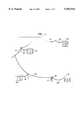
- FIG. 1is a diagram of a power line system connecting residential units
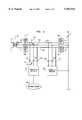
- FIG. 2is a schematic diagram a communication system using power line connections between a residence and a transformer as a transmission medium;
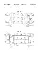
- FIGS. 3 and 4are schematic diagrams of transmitters/receivers in two directions using the same set of power lines
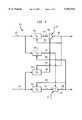
- FIG. 5is a schematic diagram of a first adaptive equalizer configuration used in the transmitter/receivers shown in FIGS. 3 and 4;
- FIG. 6is a schematic diagram of a typical least-mean-square adaptive equalizer
- FIG. 7is a diagram of a second adaptive equalizer configuration
- FIG. 8is a schematic diagram of a combination of echo canceller and a hybrid line driver/receiver device for transmitting and receiving data;
- FIG. 9is a schematic diagram of a hybrid circuit as presented in FIG. 8.
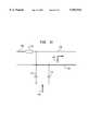
- FIG. 10is a diagram of a power-neutral line pair.
- FIG. 1shows power line 118 connected to individual residential units 102, 104, 106 and 108.
- the power lineis connected to a transformer 120 which converts power from high voltage lines to power to be supplied to the residential units 102, 104, 106 and 108.
- Each of the residential units 102, 104, 106 and 108are individually connected to the power line 118 through connection lines 116, 114, 112 and 110, respectively.
- a central transmitter/receiver 122is coupled to the power line near the transformer 120.
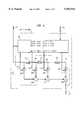
- FIG. 2shows a schematic diagram of the connection of transformer 120 to the house 108.
- the secondary side of the transformer 120includes three lines 208, 210 and 212.
- the lines 208 and 212are power lines and the line 210 is a neutral line.
- the voltage between each of the power lines 208 and 212 and the neutral line 210is at about 110 volts AC.
- the phase difference between the power lines 208 and 212are about 180 degrees apart so that the voltage between the power lines 208 and 212 is about 220 volts AC.
- Signal choke blocks 214 and 216are connected in series with the power lines 208 and 212, respectively at the transformer.
- the lines 210, 236 and 238form a power line drop from the transformer 120 to the residential unit 108.
- the signal choke blocks 218 and 220are connected in series to the power lines 236 and 238, respectively, at the residential unit end of the power line drop.
- the signal choke blocks 218 and 220are also connected to power lines 240 and 242 that supply power to the residential unit 108.
- the signal choke blocks 214, 216, 218, and 220are intended to isolate RF signals on the power line drop from impedance variations and noises from the transformer and the residential unit 108.
- the transmitter/receiver 122 and a transmitter/receiver 202are coupled to the power lines 236 and 238 via coupling capacitors 222-232.
- the transmitter/receiver 122is also coupled to a communication network such as telephone network 234.
- the transmitter/receiver 202is coupled to terminal(s) located within the residential unit 108. Thus, communication between the terminal(s) within the residential unit 108 and other terminal(s) coupled to the telephone network 234 may be accomplished.
- the signal choke blocks 214 and 216decouple noise signals on the lines 208, 210 and 212 from the power lines 236 and 238.
- the signal choke block 218 and 220decouple noise signals on the lines 240, 242 and 210 from the power lines 236 and 238.
- noise occurring in the communication bands generated by home appliances in the residential units 102, 104, 106 and 108are blocked from interfering with the communication between transmitter/receivers 122 and 202.
- the transmitter/receivers 122 and 202provide two duplex channels transmitting and receiving signals through the two power lines 236 and 238 and the neutral line 210.
- a first duplex channeltransmits and receives signals in the same bands through the power line 236 and the neutral line 210 while a second duplex channel transmits and receives information in the same bands using the power line 238 and the neutral line 210.
- the neutral line 210is shared between the first and the second duplex channels and the same frequency bands are used on both power-neutral line pairs 236 and 210, 238 and 210 for both transmit and receive signals. Because the neutral line 210 is shared, signals in the first duplex channel may be cross-coupled to the second duplex channel and vice versa. This cross-coupling reduces the signal-to-noise ratio so that transmission using two duplex channels is difficult without compensation. Thus, the cross-coupling through the neutral line 210 must be canceled before the two duplex channels can operate independently.
- the transmitter/receivers 122 and 202cancel the cross-coupling between the first and second duplex channels as well as performing equalization of the transmission channels by using adaptive filters.
- the transmitter/receivers 122 and 202are able to provide two duplex channel communication between the residential unit 108 and the telephone network 234 over the same frequency bands.
- the adaptive filtersare described in detail below.
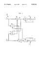
- FIGS. 3 and 4show a schematic diagram of the connection between line drivers and line receivers of the transmitter/receivers 122 and 202.
- the transmitter/receiver 122includes differential line drivers 302 and 304 corresponding to the first and the second duplex channels forward inputs.
- the line driver 302receives an input signal from signal line 318 and the line driver 304 receives an input signal from input signal line 320.
- the line driver 302outputs a differential signal between the power line 236 and the neutral line 210 through the coupling capacitors 222 and 224.
- the line driver 304outputs a differential signal to the power line 238 and the neutral line 210 through coupling capacitors 226 and 224, respectively.
- Line receivers 306 and 308 of the transmitter/receiver 202receives the signals transmitted by the transmitter/receiver 122 through the power lines 236 and 238 and the neutral line 210.
- the output of the line receivers 306 and 308are connected to an adaptive filter unit 309 through signal lines 322 and 324.
- the adaptive filtering unit 309performs line equalization and cross-coupling cancellation to improve the signal-to-noise ratios of the signals output to the signal lines 326 and 328 corresponding to the first and the second duplex channels forward outputs.
- FIG. 4shows a similar diagram as FIG. 3 but with the signals flowing in the opposite direction.
- Reverse inputs on 327 and 329 connected to line drivers 314 and 316 of the transmitter/receiver 202transmit signals onto the power lines 236 and 238 and the neutral line 210.
- Line receivers 310 and 312 of the transmitter/receiver 122receive the transmitted signals and output the received signals onto signal lines 330 and 332 to be input into adaptive filter unit 311.
- the adaptive filter unit 311performs line equalization and cross-coupling cancellation to output received signals onto signal lines 319 and 321 corresponding to the first and the second duplex channel reverse outputs.
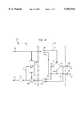
- FIG. 5shows a block diagram of an adaptive filter unit such as the adaptive filter unit 309.
- the adaptive filter unit 309includes four adaptive filters H 11 402, H 12 404, H 21 406 and H 22 408.
- the adaptive filter H 11 402receives an input signal from the signal line 322 and outputs a filtered signal to a positive input of a summer 414 through signal line 340.
- the adaptive filter H 21 406receives an input signal from signal line 324 and outputs a filtered signal to a negative input of the summer 414 through signal line 350.
- the summer 414subtracts the output of the adaptive filter H 21 406 from the output of the adaptive filter H 11 402 to generate an output signal on the signal line 326.
- the adaptive filters H 11 402 and H 21 406receive the output of the summer 414 as a feedback error signal through signal lines 342 and 348, respectively.
- data reference signals d 1are input to a negative terminal of the summer 414.
- the data reference signals d 1are required for H 11 402 to converge and may be data training sequence signals and/or decision feedbacks from final channel data decision outputs of a downstream receiver (not shown), for example.
- the adaptive filter H 22 408receives an input signal from the signal line 324 and outputs a filtered signal to a positive input of a summer 416 through signal line 354.
- the adaptive filter H 12 404receives an input signal from the signal line 322 and outputs a filtered signal to a negative input of summer 416 through signal line 344.
- the summer 416subtracts the output from the adaptive filter H 12 404 from the output of the adaptive filter H 22 408 to generate an output signal on the signal line 328.
- the adaptive filters H 22 408 and H 12 404receive the output of the summer 416 as a feedback error signal through signal lines 352 and 346, respectively. Similar to summer 414, data reference signals d 2 are input to a negative terminal of the summer 416 and are required for H 22 408 to converge.
- the adaptive filters H 11 402 and H 22 408provide line equalization of the input signals received from the signal lines 322 and 324, respectively.
- the adaptive filters H 12 404 and H 21 406adaptively cancel cross-coupling of the input signals between the signal lines 322 and 324 and the neutral line 210.
- FIG. 6shows an exemplary embodiment of a linear adaptive filter such as the adaptive filters H 11 402, H 12 404, H 21 406 and H 22 408 in greater detail. While different adaptive filters may be used such as linear and decision feedback equalizers, FIG. 6 shows a finite-impulse-response (FIR) least-mean-square-error (MMSE) adaptive filter as an example.
- the filter portion 502receives the input signal from signal line 322 and delays the input signal by delay units 520, 522 and 524. As indicated by the dotted portion of signal line 536, any number of delay units 520, 522 and 524 may be used depending on particular design requirements of the least-mean-square adaptive filter.
- FIRfinite-impulse-response
- MMSEleast-mean-square-error
- the delay units 520, 522 and 524delay the input signal by some integer fraction of one symbol sub-unit time Ts/K.
- the delay units 520, 522 and 524, multiplier units 506, 508, 510 and 512 and adder units 514, 516 and 518together form a filter that filters the input signal on signal line 322 and outputs the filtered input signal through signal line 328.
- the filter characteristicsare determined by the weights W 1 , W 2 , W 3 . . . . W M , where M is the length of the filter. Depending on the particular values of the weights, the frequency characteristic of the filter will be determined.
- the weights W 1 , W 2 , . . . W Mare adaptive weights.
- the adaptive weightsare updated and the updated weights are used by the multipliers 506, 508, 510 and 512 as indicated by the lines connecting a weight update unit 504 and the multipliers 506, 508, 510 and 512.
- the weight update unit 504calculates new weights based on the current set of weights adjusted by a factor which is a product of a constant g multiplied by the error signal ⁇ (j) multiplied by the input signal h(j), where j is the current time.
- the constant gis selected so that the weight update algorithm converges to generate an optimum set of weights W 1 , W 2 . . . W M that results in the best signal-to-noise ratio within the constraint of adaptivity to changing system conditions.
- the error signal ⁇ (j)is the output of the summer 414 to adapt H 11 402 shown in FIG. 5, for example.
- the input signal h(j)is delayed corresponding to the total number of delays applied to the input signal by delay units 520, 522 and 524.
- the input signal used to update W 1is an undelayed input signal h(j).
- W 2is updated by using the input signal delayed by the delay unit 520, and so on.
- the weight update unit 504generates weights adaptively to minimize, in the mean-square-error sense, the difference between the output of H 11 402 and the desired reference d 1 .
- a similar adaptive filteris used for H 21 406, and this is also adjusted by the error output of summer 414 to minimize the cross-coupled component in the final output 326.
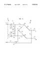
- FIG. 7shows an adaptive filter unit 609 that is an alternative embodiment to the adaptive filter unit 309.
- the adaptive filter unit 609includes the adaptive filters H 11 410, H 12 404, H 21 406 and H 22 412.
- the adaptive filter unit 609also includes two summers 418 and 420 for cross terms and two summers 422 and 424 for referencing to desired data d 1 and d 2
- the adaptive filter H 11 410is connected to the output of the summer 418 instead of between the signal line 322 and the summer 418 as in the adaptive filter unit 309.
- the adaptive filter H 22 412is connected to the output of the summer 420.
- the adaptive filter unit 609performs line equalization after canceling the cross-coupling between the signal lines 322 and 324. There may be practical performance advantages to using the two-stage method of FIG. 7.
- FIG. 8shows a hybrid line driver/receiver device 500 that includes an echo cancellation device 530 between signal lines 318 and 330 and a transmitter/receiver hybrid 532.
- the hybrid line driver/receiver device 500performs a similar function as the line driver 302 and the line receiver 310 shown in FIG. 4.
- the transmitter/receiver hybrid 532includes a differential line driver 513, a differential line receiver 509, and a balanced bridge 506.
- the echo cancellation device 530includes an adaptive filter 514, a summer 510 and a buffer 511.
- the differential line driver 513drives the balanced bridge circuit 506 at top and bottom nodes 518 and 520, respectively.
- the differential line receiver 509receives signals from right and left bridge nodes 524 and 522.
- the output of the differential line receiver 509is input to a positive input of the summer 510 through signal line 518.
- the adaptive filter 514receives an input signal from signal line 318 and outputs a filtered signal to a negative input of the summer 510 through signal line 516.
- the summer 510subtracts the filtered signal from the output of the differential line receiver 509 and outputs the result to the buffer 511 which generates an output to signal line 330.
- the adaptive filterreceives the output of the summer 510 through signal line 512 as a feedback error signal.
- the adaptive filter 514may be implemented using techniques such as linear and decision feedback equalizers and echo cancellers that are well known to one of ordinary skill in the art.
- the finite-impulse-response (FIR) least-mean square-error (MMSE) adaptive filter as shown in FIG. 6may be used.
- the function of the adaptive filter 514is to remove a signal correlated with the signal on line 318 that has been coupled to the signal line 518 via the differential line driver 513 and any imbalance in the balanced bridge circuit 506.
- the adaptive filter 514adaptively adjusts weights so that the echo cancellation may account for variations in specific conditions encountered during operation.
- FIG. 9shows a circuit diagram of the differential line driver 513 and the balanced bridge circuit 506.
- the differential line driver 513may include two buffers 602 and 612 connected in voltage follower configurations together with resistors 606, 608 and 616.
- the positive input terminal of the buffer 612is connected to a circuit ground reference via signal line 614.
- the positive terminal of the buffer 602is connected to the signal line 318.
- a signal on the signal line 318is applied differentially across the bridge nodes 518 and 520 and hence differentially across the power-neutral line pair 236 and 210.
- Resistors 606, 608 and 616control the gain of the differential amplifier.
- the balanced bridge circuit 506includes two legs between the nodes 518 and 520.
- the left legincludes a resistor 522 and an impedance 524.
- the right legincludes a resistor 520 and an impedance that is the driving point impedance looking into the power-neutral line pair 236 and 210.
- the resistors 520 and 522have the same value and the impedance of 524 is assumed to have the same value as the line impedance across the frequency bands of interest for the RF signal transmission.
- the voltage between nodes 522 and 526is unaffected when the balanced bridge circuit 506 is balanced. If a signal is received across the power-neutral line pair 236 and 210, the signal will be imaged across nodes 526 and 522. Thus, the voltage difference between the nodes 522 and 526 corresponds only to the signal received across power line 236 to neutral line 210 and does not contain a component of the signal between nodes 518 and 520 that is to be transmitted to the power-neutral line pair 236 and 210.
- the voltage between the nodes 522 and 526is coupled to the differential line receiver 509 through signal lines 508 and 507.
- the balanced bridge circuit 506permits transmitting signals out to the power-neutral line pair 236 and 210 and receiving signals from the power-neutral line pair 236 and 210 in the same bands and at the same time with minimal interference between the transmitted signal and the received signal.
- the value of the impedance 524is determined based on the transmission line impedance seen looking into the power-neutral line pair 236 and 210.
- FIG. 10shows impedance values observed from arrows 702 and 704.
- the impedance 524is set to the value of the impedance as observed from arrow 704 which includes: 1) the impedance of the transmission line as seen from arrow 702; 2) the equivalent impedance represented by the coupling capacitors 222 and 224 as well as the signal choke block 214; and 3) the impedance between power line 208 and the neutral line 210 representing the load of the transformer 120.
- 524would be determined by the impedance observed looking into power-neutral line pair 236 and 210, the signal choke block 218, and impedance across power-neutral line pair 240 and 210 for application at the transmitter/receiver 202.
Landscapes
- Engineering & Computer Science (AREA)
- Computer Networks & Wireless Communication (AREA)
- Signal Processing (AREA)
- Cable Transmission Systems, Equalization Of Radio And Reduction Of Echo (AREA)
Abstract
Description
Claims (26)
Priority Applications (2)
| Application Number | Priority Date | Filing Date | Title |
|---|---|---|---|
| US08/926,609US5952914A (en) | 1997-09-10 | 1997-09-10 | Power line communication systems |
| EP98306830AEP0902550A3 (en) | 1997-09-10 | 1998-08-26 | Power line communication systems |
Applications Claiming Priority (1)
| Application Number | Priority Date | Filing Date | Title |
|---|---|---|---|
| US08/926,609US5952914A (en) | 1997-09-10 | 1997-09-10 | Power line communication systems |
Publications (1)
| Publication Number | Publication Date |
|---|---|
| US5952914Atrue US5952914A (en) | 1999-09-14 |
Family
ID=25453443
Family Applications (1)
| Application Number | Title | Priority Date | Filing Date |
|---|---|---|---|
| US08/926,609Expired - LifetimeUS5952914A (en) | 1997-09-10 | 1997-09-10 | Power line communication systems |
Country Status (2)
| Country | Link |
|---|---|
| US (1) | US5952914A (en) |
| EP (1) | EP0902550A3 (en) |
Cited By (80)
| Publication number | Priority date | Publication date | Assignee | Title |
|---|---|---|---|---|
| US6297729B1 (en)* | 1999-03-29 | 2001-10-02 | International Business Machines Corporation | Method and apparatus for securing communications along ac power lines |
| US6323756B1 (en)* | 1997-09-02 | 2001-11-27 | Matsushita Electric Industrial Co., Ltd. | Data transmitter |
| US20010045888A1 (en)* | 2000-01-20 | 2001-11-29 | Kline Paul A. | Method of isolating data in a power line communications network |
| US20020110311A1 (en)* | 2001-02-14 | 2002-08-15 | Kline Paul A. | Apparatus and method for providing a power line communication device for safe transmission of high-frequency, high-bandwidth signals over existing power distribution lines |
| US20020110310A1 (en)* | 2001-02-14 | 2002-08-15 | Kline Paul A. | Method and apparatus for providing inductive coupling and decoupling of high-frequency, high-bandwidth data signals directly on and off of a high voltage power line |
| US6492897B1 (en) | 2000-08-04 | 2002-12-10 | Richard A. Mowery, Jr. | System for coupling wireless signals to and from a power transmission line communication system |
| US20030007503A1 (en)* | 2000-12-26 | 2003-01-09 | Wolfgang Daum | Method and apparatus for interfacing a power line carrier and an appliance |
| KR100374154B1 (en)* | 2000-06-24 | 2003-02-26 | 장학선 | System for receiving and transmitting power signal and data signal |
| US20030046377A1 (en)* | 2000-12-27 | 2003-03-06 | Wolfgang Daum | Method and apparatus for appliance service diagnostics |
| US20030095036A1 (en)* | 2001-11-19 | 2003-05-22 | Tdk Corporation | Power line communication system and power line branching apparatus |
| US6590493B1 (en)* | 2000-12-05 | 2003-07-08 | Nortel Networks Limited | System, device, and method for isolating signaling environments in a power line communication system |
| US20030160684A1 (en)* | 1999-12-30 | 2003-08-28 | Ambient Corporation | Inductive coupling of a data signal for a power transmission cable |
| WO2003071708A1 (en)* | 2002-02-21 | 2003-08-28 | Rutherford J G | A communications system utilising electricity cabling |
| US20030189495A1 (en)* | 2002-04-03 | 2003-10-09 | Pettler Peter R. | Method and system for controlling a selected electrical load in a building |
| US6633228B1 (en)* | 1999-02-22 | 2003-10-14 | Siemens Aktiengesellschaft | Communication system for simultaneous two-channel transmission of data between subscribers |
| US20030210135A1 (en)* | 2002-03-14 | 2003-11-13 | Ambient Corporation | Protecting medium voltage inductive coupled device from electrical transients |
| US20040003934A1 (en)* | 2002-06-24 | 2004-01-08 | Cope Leonard David | Power line coupling device and method of using the same |
| US20040047406A1 (en)* | 1997-09-23 | 2004-03-11 | Hunt Technologies, Inc. | Low frequency bilateral communication over distributed power lines |
| US6727804B1 (en) | 2002-07-23 | 2004-04-27 | Domosys Corporation | Power line communication system and method |
| US6741045B2 (en) | 2002-04-23 | 2004-05-25 | Shimano, Inc. | Bicycle control apparatus that communicates power and data over a single transmission path |
| WO2004055994A3 (en)* | 2002-12-13 | 2004-08-12 | Current Tech Llc | A power line communication system and method of using the same |
| US6791454B2 (en)* | 2000-11-17 | 2004-09-14 | Siemens Aktiengesellschaft | Cable |
| US20050007241A1 (en)* | 2000-01-20 | 2005-01-13 | Kline Paul A. | Method of isolating data in a power line communications network |
| US20050168326A1 (en)* | 2002-12-10 | 2005-08-04 | Current Technologies, Llc | Power line repeater system and method |
| US6933835B2 (en) | 2001-02-14 | 2005-08-23 | Current Technologies, Llc | Data communication over a power line |
| US20050190871A1 (en)* | 2004-02-26 | 2005-09-01 | Hossein Sedarat | Multicarrier communication using a time domain equalizing filter |
| US6958680B2 (en) | 2000-04-14 | 2005-10-25 | Current Technologies, Llc | Power line communication system and method of using the same |
| US6965303B2 (en) | 2002-12-10 | 2005-11-15 | Current Technologies, Llc | Power line communication system and method |
| US6980090B2 (en)* | 2002-12-10 | 2005-12-27 | Current Technologies, Llc | Device and method for coupling with electrical distribution network infrastructure to provide communications |
| US6980091B2 (en) | 2002-12-10 | 2005-12-27 | Current Technologies, Llc | Power line communication system and method of operating the same |
| US6998962B2 (en) | 2000-04-14 | 2006-02-14 | Current Technologies, Llc | Power line communication apparatus and method of using the same |
| US20060061323A1 (en)* | 2002-10-28 | 2006-03-23 | Cheng Lily K | Contact-less power transfer |
| US20060097573A1 (en)* | 2004-10-26 | 2006-05-11 | Gidge Brett D | Power line communications system and method of operating the same |
| US7053756B2 (en) | 2001-12-21 | 2006-05-30 | Current Technologies, Llc | Facilitating communication of data signals on electric power systems |
| US7064654B2 (en) | 2002-12-10 | 2006-06-20 | Current Technologies, Llc | Power line communication system and method of operating the same |
| US7075414B2 (en) | 2003-05-13 | 2006-07-11 | Current Technologies, Llc | Device and method for communicating data signals through multiple power line conductors |
| US20060152344A1 (en)* | 2002-12-07 | 2006-07-13 | Mowery Richard A Jr | Powerline Communication Network Handoff |
| US7091849B1 (en) | 2004-05-06 | 2006-08-15 | At&T Corp. | Inbound interference reduction in a broadband powerline system |
| US7102478B2 (en) | 2002-06-21 | 2006-09-05 | Current Technologies, Llc | Power line coupling device and method of using the same |
| US7113134B1 (en) | 2004-03-12 | 2006-09-26 | Current Technologies, Llc | Transformer antenna device and method of using the same |
| US7132819B1 (en) | 2002-11-12 | 2006-11-07 | Current Technologies, Llc | Floating power supply and method of using the same |
| US20060255930A1 (en)* | 2005-05-12 | 2006-11-16 | Berkman William H | Power line communications system and method |
| US20060267757A1 (en)* | 2005-05-31 | 2006-11-30 | Lee Fu C | Activator circuit responsive to power line disturbances |
| US7154382B2 (en) | 1999-12-30 | 2006-12-26 | Ambient Corporation | Arrangement of inductive couplers for data communication |
| US20060291575A1 (en)* | 2003-07-03 | 2006-12-28 | Berkman William H | Power Line Communication System and Method |
| US7173938B1 (en) | 2001-05-18 | 2007-02-06 | Current Grid, Llc | Method and apparatus for processing outbound data within a powerline based communication system |
| US7194528B1 (en) | 2001-05-18 | 2007-03-20 | Current Grid, Llc | Method and apparatus for processing inbound data within a powerline based communication system |
| US7199699B1 (en) | 2002-02-19 | 2007-04-03 | Current Technologies, Llc | Facilitating communication with power line communication devices |
| US20070201494A1 (en)* | 2002-06-07 | 2007-08-30 | Heng Lou | Last Leg Utility Grid High-Speed Data Communication Network Having Virtual Local Area Network Functionality |
| US7265664B2 (en) | 2005-04-04 | 2007-09-04 | Current Technologies, Llc | Power line communications system and method |
| US7340509B2 (en) | 2002-07-18 | 2008-03-04 | General Electric Company | Reconfigurable appliance control system |
| US7424031B2 (en) | 1998-07-28 | 2008-09-09 | Serconet, Ltd. | Local area network of serial intelligent cells |
| US7460467B1 (en) | 2003-07-23 | 2008-12-02 | Current Technologies, Llc | Voice-over-IP network test device and method |
| US20080315971A1 (en)* | 2007-06-21 | 2008-12-25 | Radtke William O | Power Line Data Signal Attenuation Device and Method |
| US20090109981A1 (en)* | 2007-10-25 | 2009-04-30 | Michael Keselman | Out-of-band management for broadband over powerline network |
| US20090124209A1 (en)* | 2007-11-08 | 2009-05-14 | Michael Keselman | Methods and system for configuration of broadband over power lines |
| US20090125255A1 (en)* | 2007-11-08 | 2009-05-14 | Michael Keselman | Methods and apparatus for measuring voltage and voltage phase angle on bpl line |
| US20090153133A1 (en)* | 2007-12-13 | 2009-06-18 | Michael Keselman | Methods and apparatus for collecting characteristics of a power line a bpl system |
| US7656904B2 (en) | 2003-03-13 | 2010-02-02 | Mosaid Technologies Incorporated | Telephone system having multiple distinct sources and accessories therefor |
| US7675190B1 (en) | 1999-12-08 | 2010-03-09 | Current Communications International Holding Gmbh | Assembly for transmitting information via a low-voltage power supply network |
| US7675897B2 (en) | 2005-09-06 | 2010-03-09 | Current Technologies, Llc | Power line communications system with differentiated data services |
| US7764943B2 (en) | 2006-03-27 | 2010-07-27 | Current Technologies, Llc | Overhead and underground power line communication system and method using a bypass |
| US7795994B2 (en)* | 2007-06-26 | 2010-09-14 | Current Technologies, Llc | Power line coupling device and method |
| US7813439B2 (en) | 2006-02-06 | 2010-10-12 | Broadcom Corporation | Various methods and apparatuses for impulse noise detection |
| US7852950B2 (en) | 2005-02-25 | 2010-12-14 | Broadcom Corporation | Methods and apparatuses for canceling correlated noise in a multi-carrier communication system |
| US7852837B1 (en) | 2003-12-24 | 2010-12-14 | At&T Intellectual Property Ii, L.P. | Wi-Fi/BPL dual mode repeaters for power line networks |
| US7876174B2 (en) | 2007-06-26 | 2011-01-25 | Current Technologies, Llc | Power line coupling device and method |
| US7876767B2 (en) | 2000-04-19 | 2011-01-25 | Mosaid Technologies Incorporated | Network combining wired and non-wired segments |
| US20110018704A1 (en)* | 2009-07-24 | 2011-01-27 | Burrows Zachary M | System, Device and Method for Providing Power Line Communications |
| US20110026621A1 (en)* | 2009-08-03 | 2011-02-03 | Texas Instruments Incorporated | Ofdm transmission methods in three phase modes |
| US20110051820A1 (en)* | 2009-08-28 | 2011-03-03 | Enphase Energy, Inc. | Power line communications apparatus |
| US7953163B2 (en) | 2004-11-30 | 2011-05-31 | Broadcom Corporation | Block linear equalization in a multicarrier communication system |
| US8194722B2 (en) | 2004-10-11 | 2012-06-05 | Broadcom Corporation | Various methods and apparatuses for impulse noise mitigation |
| US8279058B2 (en) | 2008-11-06 | 2012-10-02 | Current Technologies International Gmbh | System, device and method for communicating over power lines |
| US8462902B1 (en) | 2004-12-01 | 2013-06-11 | At&T Intellectual Property Ii, L.P. | Interference control in a broadband powerline communication system |
| US8472533B2 (en) | 2008-10-10 | 2013-06-25 | Broadcom Corporation | Reduced-complexity common-mode noise cancellation system for DSL |
| US8952793B2 (en) | 2010-04-28 | 2015-02-10 | Shimaro Inc. | Bicycle electrical system |
| US9172429B2 (en) | 2004-12-01 | 2015-10-27 | At&T Intellectual Property Ii, L.P. | Interference control in a broadband powerline communication system |
| US9374257B2 (en) | 2005-03-18 | 2016-06-21 | Broadcom Corporation | Methods and apparatuses of measuring impulse noise parameters in multi-carrier communication systems |
| CN118646443A (en)* | 2024-08-07 | 2024-09-13 | 厦门立林科技有限公司 | A method and device for adaptive noise reduction carrier communication based on smart home |
Families Citing this family (10)
| Publication number | Priority date | Publication date | Assignee | Title |
|---|---|---|---|---|
| RU2186463C2 (en)* | 1999-12-20 | 2002-07-27 | Цагарейшвили Северьян Александрович | Method for receiving and transmitting signal in three-phase power mains |
| RU2186464C2 (en)* | 1999-12-20 | 2002-07-27 | Гутин Клавдий Иосифович | System for transmitting and receiving signals in three-phase power mains |
| RU2186461C2 (en)* | 2000-05-30 | 2002-07-27 | Цагарейшвили Северьян Александрович | Device for transmitting and receiving signals over radio channel |
| KR20020032024A (en)* | 2000-10-25 | 2002-05-03 | 이기원 | Apparatus For optimizing emergency power source in order to powerline Communication and method therefore |
| RU2190300C1 (en)* | 2000-12-28 | 2002-09-27 | Грязнов Михаил Сергеевич | Signal transmission system in three-phase power mains |
| DE10226350B4 (en)* | 2002-06-13 | 2004-09-09 | Infineon Technologies Ag | Method and device for determining the electrical properties of a data line |
| DE10234725B4 (en)* | 2002-07-30 | 2004-09-23 | Infineon Technologies Ag | Transceiver with integrated hybrid circuit |
| DE102005030368A1 (en)* | 2005-06-29 | 2006-09-21 | Siemens Ag | Bi-directional communication method for communication unit, involves performing full duplex communication between transmitter and receiver in communication unit, and launching transmission signals out-of phase in receiver section |
| EP1775851B1 (en)* | 2005-10-13 | 2011-01-19 | Broadband United GmbH | Crosstalk compensation circuit, unit and method |
| RU2405251C2 (en)* | 2008-12-15 | 2010-11-27 | Закрытое акционерное общество "Проектно-конструкторское бюро" "РИО" | Low-frequency band transmission system |
Citations (18)
| Publication number | Priority date | Publication date | Assignee | Title |
|---|---|---|---|---|
| US3942168A (en)* | 1975-01-31 | 1976-03-02 | Westinghouse Electric Corporation | Distribution network power line communication system |
| US4060735A (en)* | 1976-07-12 | 1977-11-29 | Johnson Controls, Inc. | Control system employing a programmable multiple channel controller for transmitting control signals over electrical power lines |
| US4142178A (en)* | 1977-04-25 | 1979-02-27 | Westinghouse Electric Corp. | High voltage signal coupler for a distribution network power line carrier communication system |
| US4311964A (en)* | 1979-09-21 | 1982-01-19 | Westinghouse Electric Corp. | Coherent phase shift keyed demodulator for power line communication systems |
| US4475193A (en)* | 1982-09-30 | 1984-10-02 | Astech, Inc. | Power line carrier multi telephone extension system for full duplex conferencing between telephones |
| US4479215A (en)* | 1982-09-24 | 1984-10-23 | General Electric Company | Power-line carrier communications system with interference avoidance capability |
| US4510611A (en)* | 1982-11-19 | 1985-04-09 | General Electric Company | Transceiver circuit for interfacing between a power line communication system and a data processor |
| US4514594A (en)* | 1982-09-30 | 1985-04-30 | Astech, Inc. | Power line carrier telephone extension system for full duplex conferencing between telephones and having telephone call hold capability |
| US4633218A (en)* | 1983-12-19 | 1986-12-30 | Honeywell Inc. | Apparatus for receiving low level digital signals transmitted over power lines |
| US5066939A (en)* | 1989-10-04 | 1991-11-19 | Mansfield Jr Amos R | Method and means of operating a power line carrier communication system |
| US5257006A (en)* | 1990-09-21 | 1993-10-26 | Echelon Corporation | Method and apparatus for power line communications |
| US5391932A (en)* | 1993-07-20 | 1995-02-21 | Echelon Corporation | Source power coupler |
| US5404127A (en)* | 1991-05-10 | 1995-04-04 | Echelon Corporation | Power line communication while avoiding determinable interference harmonics |
| US5491463A (en)* | 1993-06-28 | 1996-02-13 | Advanced Control Technologies, Inc. | Power line communication system |
| US5581229A (en)* | 1990-12-19 | 1996-12-03 | Hunt Technologies, Inc. | Communication system for a power distribution line |
| US5684450A (en)* | 1992-10-22 | 1997-11-04 | Norweb Plc | Electricity distribution and/or power transmission network and filter for telecommunication over power lines |
| US5691691A (en)* | 1997-01-06 | 1997-11-25 | Motorola, Inc. | Power-line communication system using pulse transmission on the AC line |
| US5694108A (en)* | 1996-05-01 | 1997-12-02 | Abb Power T&D Company Inc. | Apparatus and methods for power network coupling |
Family Cites Families (2)
| Publication number | Priority date | Publication date | Assignee | Title |
|---|---|---|---|---|
| US4357598A (en)* | 1981-04-09 | 1982-11-02 | Westinghouse Electric Corp. | Three-phase power distribution network communication system |
| US4668934A (en)* | 1984-10-22 | 1987-05-26 | Westinghouse Electric Corp. | Receiver apparatus for three-phase power line carrier communications |
- 1997
- 1997-09-10USUS08/926,609patent/US5952914A/ennot_activeExpired - Lifetime
- 1998
- 1998-08-26EPEP98306830Apatent/EP0902550A3/ennot_activeWithdrawn
Patent Citations (18)
| Publication number | Priority date | Publication date | Assignee | Title |
|---|---|---|---|---|
| US3942168A (en)* | 1975-01-31 | 1976-03-02 | Westinghouse Electric Corporation | Distribution network power line communication system |
| US4060735A (en)* | 1976-07-12 | 1977-11-29 | Johnson Controls, Inc. | Control system employing a programmable multiple channel controller for transmitting control signals over electrical power lines |
| US4142178A (en)* | 1977-04-25 | 1979-02-27 | Westinghouse Electric Corp. | High voltage signal coupler for a distribution network power line carrier communication system |
| US4311964A (en)* | 1979-09-21 | 1982-01-19 | Westinghouse Electric Corp. | Coherent phase shift keyed demodulator for power line communication systems |
| US4479215A (en)* | 1982-09-24 | 1984-10-23 | General Electric Company | Power-line carrier communications system with interference avoidance capability |
| US4475193A (en)* | 1982-09-30 | 1984-10-02 | Astech, Inc. | Power line carrier multi telephone extension system for full duplex conferencing between telephones |
| US4514594A (en)* | 1982-09-30 | 1985-04-30 | Astech, Inc. | Power line carrier telephone extension system for full duplex conferencing between telephones and having telephone call hold capability |
| US4510611A (en)* | 1982-11-19 | 1985-04-09 | General Electric Company | Transceiver circuit for interfacing between a power line communication system and a data processor |
| US4633218A (en)* | 1983-12-19 | 1986-12-30 | Honeywell Inc. | Apparatus for receiving low level digital signals transmitted over power lines |
| US5066939A (en)* | 1989-10-04 | 1991-11-19 | Mansfield Jr Amos R | Method and means of operating a power line carrier communication system |
| US5257006A (en)* | 1990-09-21 | 1993-10-26 | Echelon Corporation | Method and apparatus for power line communications |
| US5581229A (en)* | 1990-12-19 | 1996-12-03 | Hunt Technologies, Inc. | Communication system for a power distribution line |
| US5404127A (en)* | 1991-05-10 | 1995-04-04 | Echelon Corporation | Power line communication while avoiding determinable interference harmonics |
| US5684450A (en)* | 1992-10-22 | 1997-11-04 | Norweb Plc | Electricity distribution and/or power transmission network and filter for telecommunication over power lines |
| US5491463A (en)* | 1993-06-28 | 1996-02-13 | Advanced Control Technologies, Inc. | Power line communication system |
| US5391932A (en)* | 1993-07-20 | 1995-02-21 | Echelon Corporation | Source power coupler |
| US5694108A (en)* | 1996-05-01 | 1997-12-02 | Abb Power T&D Company Inc. | Apparatus and methods for power network coupling |
| US5691691A (en)* | 1997-01-06 | 1997-11-25 | Motorola, Inc. | Power-line communication system using pulse transmission on the AC line |
Non-Patent Citations (14)
| Title |
|---|
| "A Model For Communication Signal Propagation On Three Phase Power Distribution Lines", Authors: M.E. Hardy, S. Ardlan, J.B. O'Neal, Jr., L.J. Gale & K.C. Shuey, IEEE Transactions on Power Delivery, vol. 6, No. 3, Jul. 1991, pp. 966-972. |
| "Coupled Transmission Line Networks in a Inhomogeneous Dielectric Medium"; Authors: G.I. Zysman & A.K. Johnson, IEEE Transactions on Microwave Theory and Techniques, vol. MTT-17, No. 10, Oct. 1969, pp. 753-759. |
| "Decoupling Networks For Promoting Power Line Carrier Systems"; Author: K.S. Murthy; IEEE Transactions on Power Delivery, vol. 10, No. 2, Apr. 1995, pp. 580-587. |
| "IEEE Guide for Power-Line Carrier Applications", Institute of Electrical and Electronics Engineers, NY, NY, Committee of IEEE Power Eng. Society; Sponsor: Power System Communications, IEEE Standard 643-1980, Jan. 30, 1981, ANSI, pp. 2-63. |
| "Power-Line Carrier Systems", Authors:T.M. Swingle & H.I. Dobson, Chapter 14, pp. 14-19. |
| "Power-Line Noise Survey", Author: A. A. Smith, Jr., IEEE Transactions On Electromagnetic Compatibility, vol. T-EMC, Feb. 1972, pp. 31-32. |
| "Transmission Lines and Waveguides"; Author: R.V. Lowman, of book; Chapter 42, pp. 42-1-42-6. |
| A Model For Communication Signal Propagation On Three Phase Power Distribution Lines , Authors: M.E. Hardy, S. Ardlan, J.B. O Neal, Jr., L.J. Gale & K.C. Shuey, IEEE Transactions on Power Delivery, vol. 6, No. 3, Jul. 1991, pp. 966 972.* |
| Coupled Transmission Line Networks in a Inhomogeneous Dielectric Medium ; Authors: G.I. Zysman & A.K. Johnson, IEEE Transactions on Microwave Theory and Techniques, vol. MTT 17, No. 10, Oct. 1969, pp. 753 759.* |
| Decoupling Networks For Promoting Power Line Carrier Systems ; Author: K.S. Murthy; IEEE Transactions on Power Delivery, vol. 10, No. 2, Apr. 1995, pp. 580 587.* |
| IEEE Guide for Power Line Carrier Applications , Institute of Electrical and Electronics Engineers, NY, NY, Committee of IEEE Power Eng. Society; Sponsor: Power System Communications, IEEE Standard 643 1980, Jan. 30, 1981, ANSI, pp. 2 63.* |
| Power Line Carrier Systems , Authors:T.M. Swingle & H.I. Dobson, Chapter 14, pp. 14 19.* |
| Power Line Noise Survey , Author: A. A. Smith, Jr., IEEE Transactions On Electromagnetic Compatibility, vol. T EMC, Feb. 1972, pp. 31 32.* |
| Transmission Lines and Waveguides ; Author: R.V. Lowman, of book; Chapter 42, pp. 42 1 42 6.* |
Cited By (150)
| Publication number | Priority date | Publication date | Assignee | Title |
|---|---|---|---|---|
| US6323756B1 (en)* | 1997-09-02 | 2001-11-27 | Matsushita Electric Industrial Co., Ltd. | Data transmitter |
| US20040047406A1 (en)* | 1997-09-23 | 2004-03-11 | Hunt Technologies, Inc. | Low frequency bilateral communication over distributed power lines |
| US20090296832A1 (en)* | 1997-09-23 | 2009-12-03 | Hunt Technologies, Inc. | Low Frequency Bilateral Communication Over Distributed Power Lines |
| US20080062898A1 (en)* | 1997-09-23 | 2008-03-13 | Hunt Technologies, Inc. | Low frequency bilateral communication over distributed power lines |
| US7424031B2 (en) | 1998-07-28 | 2008-09-09 | Serconet, Ltd. | Local area network of serial intelligent cells |
| US7978726B2 (en) | 1998-07-28 | 2011-07-12 | Mosaid Technologies Incorporated | Local area network of serial intelligent cells |
| US8908673B2 (en) | 1998-07-28 | 2014-12-09 | Conversant Intellectual Property Management Incorporated | Local area network of serial intelligent cells |
| US8885659B2 (en) | 1998-07-28 | 2014-11-11 | Conversant Intellectual Property Management Incorporated | Local area network of serial intelligent cells |
| US8885660B2 (en) | 1998-07-28 | 2014-11-11 | Conversant Intellectual Property Management Incorporated | Local area network of serial intelligent cells |
| US7852874B2 (en) | 1998-07-28 | 2010-12-14 | Mosaid Technologies Incorporated | Local area network of serial intelligent cells |
| US8867523B2 (en) | 1998-07-28 | 2014-10-21 | Conversant Intellectual Property Management Incorporated | Local area network of serial intelligent cells |
| US6633228B1 (en)* | 1999-02-22 | 2003-10-14 | Siemens Aktiengesellschaft | Communication system for simultaneous two-channel transmission of data between subscribers |
| US6297729B1 (en)* | 1999-03-29 | 2001-10-02 | International Business Machines Corporation | Method and apparatus for securing communications along ac power lines |
| US7675190B1 (en) | 1999-12-08 | 2010-03-09 | Current Communications International Holding Gmbh | Assembly for transmitting information via a low-voltage power supply network |
| US20030160684A1 (en)* | 1999-12-30 | 2003-08-28 | Ambient Corporation | Inductive coupling of a data signal for a power transmission cable |
| US6897764B2 (en) | 1999-12-30 | 2005-05-24 | Ambient Corporation | Inductive coupling of a data signal for a power transmission cable |
| US7154382B2 (en) | 1999-12-30 | 2006-12-26 | Ambient Corporation | Arrangement of inductive couplers for data communication |
| US20050007241A1 (en)* | 2000-01-20 | 2005-01-13 | Kline Paul A. | Method of isolating data in a power line communications network |
| US7176786B2 (en) | 2000-01-20 | 2007-02-13 | Current Technologies, Llc | Method of isolating data in a power line communications network |
| US20010045888A1 (en)* | 2000-01-20 | 2001-11-29 | Kline Paul A. | Method of isolating data in a power line communications network |
| US6977578B2 (en) | 2000-01-20 | 2005-12-20 | Current Technologies, Llc | Method of isolating data in a power line communications network |
| US7245212B2 (en) | 2000-04-14 | 2007-07-17 | Current Technologies, Llc | Power line communication apparatus and method of using the same |
| US6958680B2 (en) | 2000-04-14 | 2005-10-25 | Current Technologies, Llc | Power line communication system and method of using the same |
| US7307511B2 (en) | 2000-04-14 | 2007-12-11 | Current Technologies, Llc | Power line communication system and method |
| US6965302B2 (en)* | 2000-04-14 | 2005-11-15 | Current Technologies, Llc | Power line communication system and method of using the same |
| US6998962B2 (en) | 2000-04-14 | 2006-02-14 | Current Technologies, Llc | Power line communication apparatus and method of using the same |
| US7876767B2 (en) | 2000-04-19 | 2011-01-25 | Mosaid Technologies Incorporated | Network combining wired and non-wired segments |
| US8982903B2 (en) | 2000-04-19 | 2015-03-17 | Conversant Intellectual Property Management Inc. | Network combining wired and non-wired segments |
| US8873586B2 (en) | 2000-04-19 | 2014-10-28 | Conversant Intellectual Property Management Incorporated | Network combining wired and non-wired segments |
| US7933297B2 (en) | 2000-04-19 | 2011-04-26 | Mosaid Technologies Incorporated | Network combining wired and non-wired segments |
| US8982904B2 (en) | 2000-04-19 | 2015-03-17 | Conversant Intellectual Property Management Inc. | Network combining wired and non-wired segments |
| US8873575B2 (en) | 2000-04-19 | 2014-10-28 | Conversant Intellectual Property Management Incorporated | Network combining wired and non-wired segments |
| US8848725B2 (en) | 2000-04-19 | 2014-09-30 | Conversant Intellectual Property Management Incorporated | Network combining wired and non-wired segments |
| US8867506B2 (en) | 2000-04-19 | 2014-10-21 | Conversant Intellectual Property Management Incorporated | Network combining wired and non-wired segments |
| KR100374154B1 (en)* | 2000-06-24 | 2003-02-26 | 장학선 | System for receiving and transmitting power signal and data signal |
| US6492897B1 (en) | 2000-08-04 | 2002-12-10 | Richard A. Mowery, Jr. | System for coupling wireless signals to and from a power transmission line communication system |
| US6791454B2 (en)* | 2000-11-17 | 2004-09-14 | Siemens Aktiengesellschaft | Cable |
| US6590493B1 (en)* | 2000-12-05 | 2003-07-08 | Nortel Networks Limited | System, device, and method for isolating signaling environments in a power line communication system |
| US20030007503A1 (en)* | 2000-12-26 | 2003-01-09 | Wolfgang Daum | Method and apparatus for interfacing a power line carrier and an appliance |
| US7170405B2 (en) | 2000-12-26 | 2007-01-30 | General Electric Company | Method and apparatus for interfacing a power line carrier and an appliance |
| US20030046377A1 (en)* | 2000-12-27 | 2003-03-06 | Wolfgang Daum | Method and apparatus for appliance service diagnostics |
| US6950567B2 (en) | 2001-02-14 | 2005-09-27 | Current Technologies, Llc | Method and apparatus for providing inductive coupling and decoupling of high-frequency, high-bandwidth data signals directly on and off of a high voltage power line |
| US7218219B2 (en) | 2001-02-14 | 2007-05-15 | Current Technologies, Llc | Data communication over a power line |
| US20020110311A1 (en)* | 2001-02-14 | 2002-08-15 | Kline Paul A. | Apparatus and method for providing a power line communication device for safe transmission of high-frequency, high-bandwidth signals over existing power distribution lines |
| US7046882B2 (en) | 2001-02-14 | 2006-05-16 | Current Technologies, Llc | Power line communication system and method |
| US20020110310A1 (en)* | 2001-02-14 | 2002-08-15 | Kline Paul A. | Method and apparatus for providing inductive coupling and decoupling of high-frequency, high-bandwidth data signals directly on and off of a high voltage power line |
| US7187276B2 (en) | 2001-02-14 | 2007-03-06 | Current Technologies, Llc | Power line communication system and method of using the same |
| US7453352B2 (en) | 2001-02-14 | 2008-11-18 | Current Technologies, Llc | Data communication over a power line |
| US20050213874A1 (en)* | 2001-02-14 | 2005-09-29 | Kline Paul A | Power line communication system and method |
| US7042351B2 (en) | 2001-02-14 | 2006-05-09 | Current Technologies, Llc | Data communication over a power line |
| US6933835B2 (en) | 2001-02-14 | 2005-08-23 | Current Technologies, Llc | Data communication over a power line |
| US7103240B2 (en) | 2001-02-14 | 2006-09-05 | Current Technologies, Llc | Method and apparatus for providing inductive coupling and decoupling of high-frequency, high-bandwidth data signals directly on and off of a high voltage power line |
| US20040246107A1 (en)* | 2001-02-14 | 2004-12-09 | Current Technologies, L.L.C. | Power line communication system and method of using the same |
| US7173938B1 (en) | 2001-05-18 | 2007-02-06 | Current Grid, Llc | Method and apparatus for processing outbound data within a powerline based communication system |
| US7194528B1 (en) | 2001-05-18 | 2007-03-20 | Current Grid, Llc | Method and apparatus for processing inbound data within a powerline based communication system |
| US20100102987A1 (en)* | 2001-05-18 | 2010-04-29 | Heng Lou | Power Line Communication Device having Virtual Local Area Network Functionality |
| US20030095036A1 (en)* | 2001-11-19 | 2003-05-22 | Tdk Corporation | Power line communication system and power line branching apparatus |
| US6987430B2 (en)* | 2001-11-19 | 2006-01-17 | Tdk Corporation | Power line communication system and power line branching apparatus |
| US7053756B2 (en) | 2001-12-21 | 2006-05-30 | Current Technologies, Llc | Facilitating communication of data signals on electric power systems |
| US7199699B1 (en) | 2002-02-19 | 2007-04-03 | Current Technologies, Llc | Facilitating communication with power line communication devices |
| WO2003071708A1 (en)* | 2002-02-21 | 2003-08-28 | Rutherford J G | A communications system utilising electricity cabling |
| US20060268487A1 (en)* | 2002-03-14 | 2006-11-30 | Ambient Corporation | Protecting medium voltage inductive coupled device from electrical transients |
| US7116007B2 (en) | 2002-03-14 | 2006-10-03 | Ambient Corporation | Protecting medium voltage inductive coupled device from electrical transients |
| US7529073B2 (en) | 2002-03-14 | 2009-05-05 | Ambient Corporation | Protecting medium voltage inductive coupled device from electrical transients |
| US20030210135A1 (en)* | 2002-03-14 | 2003-11-13 | Ambient Corporation | Protecting medium voltage inductive coupled device from electrical transients |
| WO2003079493A3 (en)* | 2002-03-14 | 2004-03-04 | Ambient Corp | Protecting medium voltage inductive coupler device |
| US20030189495A1 (en)* | 2002-04-03 | 2003-10-09 | Pettler Peter R. | Method and system for controlling a selected electrical load in a building |
| US6741045B2 (en) | 2002-04-23 | 2004-05-25 | Shimano, Inc. | Bicycle control apparatus that communicates power and data over a single transmission path |
| US20070201494A1 (en)* | 2002-06-07 | 2007-08-30 | Heng Lou | Last Leg Utility Grid High-Speed Data Communication Network Having Virtual Local Area Network Functionality |
| US7664117B2 (en) | 2002-06-07 | 2010-02-16 | Current Grid, Llc | Last leg utility grid high-speed data communication network having virtual local area network functionality |
| US7102478B2 (en) | 2002-06-21 | 2006-09-05 | Current Technologies, Llc | Power line coupling device and method of using the same |
| US7224243B2 (en) | 2002-06-24 | 2007-05-29 | Current Technologies, Llc | Power line coupling device and method of using the same |
| US20040003934A1 (en)* | 2002-06-24 | 2004-01-08 | Cope Leonard David | Power line coupling device and method of using the same |
| US6982611B2 (en) | 2002-06-24 | 2006-01-03 | Current Technologies, Llc | Power line coupling device and method of using the same |
| US7340509B2 (en) | 2002-07-18 | 2008-03-04 | General Electric Company | Reconfigurable appliance control system |
| US6727804B1 (en) | 2002-07-23 | 2004-04-27 | Domosys Corporation | Power line communication system and method |
| US20060061323A1 (en)* | 2002-10-28 | 2006-03-23 | Cheng Lily K | Contact-less power transfer |
| US7132819B1 (en) | 2002-11-12 | 2006-11-07 | Current Technologies, Llc | Floating power supply and method of using the same |
| US20060152344A1 (en)* | 2002-12-07 | 2006-07-13 | Mowery Richard A Jr | Powerline Communication Network Handoff |
| US7064654B2 (en) | 2002-12-10 | 2006-06-20 | Current Technologies, Llc | Power line communication system and method of operating the same |
| US20090134996A1 (en)* | 2002-12-10 | 2009-05-28 | White Ii Melvin Joseph | Power Line Communication System and Method of Operating the Same |
| US8198999B2 (en) | 2002-12-10 | 2012-06-12 | Current Technologies, Llc | Power line communication system and method of operating the same |
| US6980091B2 (en) | 2002-12-10 | 2005-12-27 | Current Technologies, Llc | Power line communication system and method of operating the same |
| US7301440B2 (en) | 2002-12-10 | 2007-11-27 | Current Technologies, Llc | Power line communication system and method |
| US7224272B2 (en) | 2002-12-10 | 2007-05-29 | Current Technologies, Llc | Power line repeater system and method |
| US7701325B2 (en) | 2002-12-10 | 2010-04-20 | Current Technologies, Llc | Power line communication apparatus and method of using the same |
| US7466225B2 (en) | 2002-12-10 | 2008-12-16 | Current Technologies, Llc | Power line communication system and method of operating the same |
| US7250848B2 (en) | 2002-12-10 | 2007-07-31 | Current Technologies, Llc | Power line communication apparatus and method of using the same |
| US20060038662A1 (en)* | 2002-12-10 | 2006-02-23 | White Melvin J Ii | Power line communication system and method of operating the same |
| US6965303B2 (en) | 2002-12-10 | 2005-11-15 | Current Technologies, Llc | Power line communication system and method |
| US6980090B2 (en)* | 2002-12-10 | 2005-12-27 | Current Technologies, Llc | Device and method for coupling with electrical distribution network infrastructure to provide communications |
| US20050168326A1 (en)* | 2002-12-10 | 2005-08-04 | Current Technologies, Llc | Power line repeater system and method |
| WO2004055994A3 (en)* | 2002-12-13 | 2004-08-12 | Current Tech Llc | A power line communication system and method of using the same |
| US7656904B2 (en) | 2003-03-13 | 2010-02-02 | Mosaid Technologies Incorporated | Telephone system having multiple distinct sources and accessories therefor |
| US7075414B2 (en) | 2003-05-13 | 2006-07-11 | Current Technologies, Llc | Device and method for communicating data signals through multiple power line conductors |
| US20060291575A1 (en)* | 2003-07-03 | 2006-12-28 | Berkman William H | Power Line Communication System and Method |
| US7460467B1 (en) | 2003-07-23 | 2008-12-02 | Current Technologies, Llc | Voice-over-IP network test device and method |
| US7852837B1 (en) | 2003-12-24 | 2010-12-14 | At&T Intellectual Property Ii, L.P. | Wi-Fi/BPL dual mode repeaters for power line networks |
| US10728127B2 (en) | 2003-12-24 | 2020-07-28 | At&T Intellectual Property Ii, L.P. | Wi-Fi/BPL dual mode repeaters for power line networks |
| US20050190871A1 (en)* | 2004-02-26 | 2005-09-01 | Hossein Sedarat | Multicarrier communication using a time domain equalizing filter |
| US7369607B2 (en)* | 2004-02-26 | 2008-05-06 | 2Wire, Inc. | Multicarrier communication using a time domain equalizing filter |
| US7113134B1 (en) | 2004-03-12 | 2006-09-26 | Current Technologies, Llc | Transformer antenna device and method of using the same |
| US10700737B2 (en) | 2004-05-06 | 2020-06-30 | At&T Intellectual Property Ii, L.P. | Outbound interference reduction in a broadband powerline system |
| US8938021B1 (en) | 2004-05-06 | 2015-01-20 | Paul Shala Henry | Outbound interference reduction in a broadband powerline system |
| US7091849B1 (en) | 2004-05-06 | 2006-08-15 | At&T Corp. | Inbound interference reduction in a broadband powerline system |
| US7453353B1 (en) | 2004-05-06 | 2008-11-18 | At&T Intellectual Property Ii, L.P. | Inbound interference reduction in a broadband powerline system |
| US10312965B2 (en) | 2004-05-06 | 2019-06-04 | At&T Intellectual Property Ii, L.P. | Outbound interference reduction in a broadband powerline system |
| US9577706B2 (en) | 2004-05-06 | 2017-02-21 | At&T Intellectual Property Ii, L.P. | Outbound interference reduction in a broadband powerline system |
| US9887734B2 (en) | 2004-05-06 | 2018-02-06 | At&T Intellectual Property Ii, L.P. | Outbound interference reduction in a broadband powerline system |
| US8194722B2 (en) | 2004-10-11 | 2012-06-05 | Broadcom Corporation | Various methods and apparatuses for impulse noise mitigation |
| US20060097573A1 (en)* | 2004-10-26 | 2006-05-11 | Gidge Brett D | Power line communications system and method of operating the same |
| US7321291B2 (en) | 2004-10-26 | 2008-01-22 | Current Technologies, Llc | Power line communications system and method of operating the same |
| US7953163B2 (en) | 2004-11-30 | 2011-05-31 | Broadcom Corporation | Block linear equalization in a multicarrier communication system |
| US8462902B1 (en) | 2004-12-01 | 2013-06-11 | At&T Intellectual Property Ii, L.P. | Interference control in a broadband powerline communication system |
| US8804797B2 (en) | 2004-12-01 | 2014-08-12 | At&T Intellectual Property Ii, L.P. | Interference control in a broadband powerline communication system |
| US9172429B2 (en) | 2004-12-01 | 2015-10-27 | At&T Intellectual Property Ii, L.P. | Interference control in a broadband powerline communication system |
| US7852950B2 (en) | 2005-02-25 | 2010-12-14 | Broadcom Corporation | Methods and apparatuses for canceling correlated noise in a multi-carrier communication system |
| US9374257B2 (en) | 2005-03-18 | 2016-06-21 | Broadcom Corporation | Methods and apparatuses of measuring impulse noise parameters in multi-carrier communication systems |
| US7265664B2 (en) | 2005-04-04 | 2007-09-04 | Current Technologies, Llc | Power line communications system and method |
| US20070268124A1 (en)* | 2005-04-04 | 2007-11-22 | Berkman William H | Power Line Communications System and Method |
| US7450001B2 (en) | 2005-04-04 | 2008-11-11 | Current Technologies, Llc | Power line communications system and method |
| US20060255930A1 (en)* | 2005-05-12 | 2006-11-16 | Berkman William H | Power line communications system and method |
| US20060267757A1 (en)* | 2005-05-31 | 2006-11-30 | Lee Fu C | Activator circuit responsive to power line disturbances |
| US7215245B2 (en)* | 2005-05-31 | 2007-05-08 | Fu Ching Lee | Activator circuit responsive to power line disturbances |
| US7675897B2 (en) | 2005-09-06 | 2010-03-09 | Current Technologies, Llc | Power line communications system with differentiated data services |
| US7813439B2 (en) | 2006-02-06 | 2010-10-12 | Broadcom Corporation | Various methods and apparatuses for impulse noise detection |
| US7764943B2 (en) | 2006-03-27 | 2010-07-27 | Current Technologies, Llc | Overhead and underground power line communication system and method using a bypass |
| US20080315971A1 (en)* | 2007-06-21 | 2008-12-25 | Radtke William O | Power Line Data Signal Attenuation Device and Method |
| US7714682B2 (en) | 2007-06-21 | 2010-05-11 | Current Technologies, Llc | Power line data signal attenuation device and method |
| US7876174B2 (en) | 2007-06-26 | 2011-01-25 | Current Technologies, Llc | Power line coupling device and method |
| US7795994B2 (en)* | 2007-06-26 | 2010-09-14 | Current Technologies, Llc | Power line coupling device and method |
| US20090109981A1 (en)* | 2007-10-25 | 2009-04-30 | Michael Keselman | Out-of-band management for broadband over powerline network |
| US20090124209A1 (en)* | 2007-11-08 | 2009-05-14 | Michael Keselman | Methods and system for configuration of broadband over power lines |
| US20090125255A1 (en)* | 2007-11-08 | 2009-05-14 | Michael Keselman | Methods and apparatus for measuring voltage and voltage phase angle on bpl line |
| US20090153133A1 (en)* | 2007-12-13 | 2009-06-18 | Michael Keselman | Methods and apparatus for collecting characteristics of a power line a bpl system |
| US9160381B2 (en) | 2008-10-10 | 2015-10-13 | Broadcom Corporation | Adaptive frequency-domain reference noise canceller for multicarrier communications systems |
| US8472533B2 (en) | 2008-10-10 | 2013-06-25 | Broadcom Corporation | Reduced-complexity common-mode noise cancellation system for DSL |
| US8605837B2 (en) | 2008-10-10 | 2013-12-10 | Broadcom Corporation | Adaptive frequency-domain reference noise canceller for multicarrier communications systems |
| US8279058B2 (en) | 2008-11-06 | 2012-10-02 | Current Technologies International Gmbh | System, device and method for communicating over power lines |
| US20110018704A1 (en)* | 2009-07-24 | 2011-01-27 | Burrows Zachary M | System, Device and Method for Providing Power Line Communications |
| US20110026621A1 (en)* | 2009-08-03 | 2011-02-03 | Texas Instruments Incorporated | Ofdm transmission methods in three phase modes |
| US8265197B2 (en)* | 2009-08-03 | 2012-09-11 | Texas Instruments Incorporated | OFDM transmission methods in three phase modes |
| CN102474303A (en)* | 2009-08-28 | 2012-05-23 | 恩菲斯能源公司 | Power line communication apparatus |
| CN102474303B (en)* | 2009-08-28 | 2014-12-31 | 恩菲斯能源公司 | Power line communications apparatus |
| WO2011025934A3 (en)* | 2009-08-28 | 2011-05-26 | Enphase Energy, Inc. | Power line communications apparatus |
| US8411790B2 (en) | 2009-08-28 | 2013-04-02 | Enphase Energy, Inc. | Power line communications apparatus |
| US20110051820A1 (en)* | 2009-08-28 | 2011-03-03 | Enphase Energy, Inc. | Power line communications apparatus |
| US8107516B2 (en) | 2009-08-28 | 2012-01-31 | Enphase Energy, Inc. | Power line communications apparatus |
| US8952793B2 (en) | 2010-04-28 | 2015-02-10 | Shimaro Inc. | Bicycle electrical system |
| CN118646443A (en)* | 2024-08-07 | 2024-09-13 | 厦门立林科技有限公司 | A method and device for adaptive noise reduction carrier communication based on smart home |
Also Published As
| Publication number | Publication date |
|---|---|
| EP0902550A2 (en) | 1999-03-17 |
| EP0902550A3 (en) | 2000-01-26 |
Similar Documents
| Publication | Publication Date | Title |
|---|---|---|
| US5952914A (en) | Power line communication systems | |
| US7567666B2 (en) | Method and apparatus for crosstalk mitigation | |
| US6313738B1 (en) | Adaptive noise cancellation system | |
| JP5229318B2 (en) | Single port signal repeater | |
| EP0768779A2 (en) | Suppression of distortion and interference in in multiple acces communication systems | |
| US6912208B2 (en) | Method and apparatus for equalization and crosstalk mitigation | |
| US7738654B2 (en) | Isolation of transmit and receive signals | |
| US7460662B2 (en) | Isolation of transmit and receive signals in full-duplex communication systems | |
| MXPA04010733A (en) | Full duplexing for power line data communications. | |
| WO2005036761A2 (en) | System, method and apparatus for crosstalk cancellation | |
| US4074087A (en) | Bidirectional voice frequency repeater | |
| US5719856A (en) | Transmitter/receiver interface apparatus and method for a bi-directional transmission path | |
| EP2503704B1 (en) | Method and apparatus for equalization and crosstalk mitigation | |
| NL8603247A (en) | ADAPTIVE TIME-DISCREET FILTER FOR FORMING A COMPENSATION SIGNAL FROM SYNCHRONOUS DATA SYMBOLS. | |
| JP4643151B2 (en) | Method and apparatus for reducing noise in an unbalanced channel using common-mode components | |
| US4163878A (en) | Electronic hybrid and hybrid repeater with bridge circuit | |
| US7010025B1 (en) | Circuit and method for an improved front end in duplex signal communication systems | |
| US20010024498A1 (en) | Method and apparatus for an improved analog echo canceller | |
| US8989251B2 (en) | Method and apparatus to compensate for nonlinear echo in an output of a current source | |
| US7200371B1 (en) | Inter-modulation interference inhibiting line amplifier | |
| JP3607639B2 (en) | 2-wire 4-wire conversion circuit | |
| US7813495B1 (en) | Apparatus and method for automatic gain control and echo cancellation in a network system | |
| JP2003513585A (en) | Echo compensation device | |
| HK1015557A (en) | Adaptive noise cancellation system | |
| JP2001136107A (en) | Asymmetrical transformer for telephone line |
Legal Events
| Date | Code | Title | Description |
|---|---|---|---|
| AS | Assignment | Owner name:AT&T CORP., NEW YORK Free format text:ASSIGNMENT OF ASSIGNORS INTEREST;ASSIGNOR:WYNN, WOODSON DALE;REEL/FRAME:008825/0175 Effective date:19970908 | |
| STCF | Information on status: patent grant | Free format text:PATENTED CASE | |
| FPAY | Fee payment | Year of fee payment:4 | |
| FPAY | Fee payment | Year of fee payment:8 | |
| FPAY | Fee payment | Year of fee payment:12 | |
| AS | Assignment | Owner name:AT&T PROPERTIES, LLC, NEVADA Free format text:ASSIGNMENT OF ASSIGNORS INTEREST;ASSIGNOR:AT&T CORP.;REEL/FRAME:028304/0242 Effective date:20120529 | |
| AS | Assignment | Owner name:AT&T INTELLECTUAL PROPERTY II, L.P., GEORGIA Free format text:ASSIGNMENT OF ASSIGNORS INTEREST;ASSIGNOR:AT&T PROPERTIES, LLC;REEL/FRAME:028313/0451 Effective date:20120529 | |
| AS | Assignment | Owner name:RAKUTEN, INC., JAPAN Free format text:ASSIGNMENT OF ASSIGNORS INTEREST;ASSIGNOR:AT&T INTELLECTUAL PROPERTY II, L.P.;REEL/FRAME:029195/0519 Effective date:20120719 | |
| AS | Assignment | Owner name:RAKUTEN, INC., JAPAN Free format text:CHANGE OF ADDRESS;ASSIGNOR:RAKUTEN, INC.;REEL/FRAME:037751/0006 Effective date:20150824 |