US5952782A - Surface discharge plasma display including light shielding film between adjacent electrode pairs - Google Patents
Surface discharge plasma display including light shielding film between adjacent electrode pairsDownload PDFInfo
- Publication number
- US5952782A US5952782AUS08/689,591US68959196AUS5952782AUS 5952782 AUS5952782 AUS 5952782AUS 68959196 AUS68959196 AUS 68959196AUS 5952782 AUS5952782 AUS 5952782A
- Authority
- US
- United States
- Prior art keywords
- light shielding
- shielding film
- electrodes
- display
- display electrodes
- Prior art date
- Legal status (The legal status is an assumption and is not a legal conclusion. Google has not performed a legal analysis and makes no representation as to the accuracy of the status listed.)
- Expired - Lifetime
Links
Images


Classifications
- H—ELECTRICITY
- H01—ELECTRIC ELEMENTS
- H01J—ELECTRIC DISCHARGE TUBES OR DISCHARGE LAMPS
- H01J11/00—Gas-filled discharge tubes with alternating current induction of the discharge, e.g. alternating current plasma display panels [AC-PDP]; Gas-filled discharge tubes without any main electrode inside the vessel; Gas-filled discharge tubes with at least one main electrode outside the vessel
- H01J11/20—Constructional details
- H01J11/34—Vessels, containers or parts thereof, e.g. substrates
- H01J11/44—Optical arrangements or shielding arrangements, e.g. filters, black matrices, light reflecting means or electromagnetic shielding means
- H—ELECTRICITY
- H01—ELECTRIC ELEMENTS
- H01J—ELECTRIC DISCHARGE TUBES OR DISCHARGE LAMPS
- H01J11/00—Gas-filled discharge tubes with alternating current induction of the discharge, e.g. alternating current plasma display panels [AC-PDP]; Gas-filled discharge tubes without any main electrode inside the vessel; Gas-filled discharge tubes with at least one main electrode outside the vessel
- H01J11/10—AC-PDPs with at least one main electrode being out of contact with the plasma
- H01J11/12—AC-PDPs with at least one main electrode being out of contact with the plasma with main electrodes provided on both sides of the discharge space
- H—ELECTRICITY
- H01—ELECTRIC ELEMENTS
- H01J—ELECTRIC DISCHARGE TUBES OR DISCHARGE LAMPS
- H01J9/00—Apparatus or processes specially adapted for the manufacture, installation, removal, maintenance of electric discharge tubes, discharge lamps, or parts thereof; Recovery of material from discharge tubes or lamps
- H01J9/02—Manufacture of electrodes or electrode systems
- H—ELECTRICITY
- H01—ELECTRIC ELEMENTS
- H01J—ELECTRIC DISCHARGE TUBES OR DISCHARGE LAMPS
- H01J9/00—Apparatus or processes specially adapted for the manufacture, installation, removal, maintenance of electric discharge tubes, discharge lamps, or parts thereof; Recovery of material from discharge tubes or lamps
- H01J9/20—Manufacture of screens on or from which an image or pattern is formed, picked up, converted or stored; Applying coatings to the vessel
- H01J9/205—Applying optical coatings or shielding coatings to the vessel of flat panel displays, e.g. applying filter layers, electromagnetic interference shielding layers, anti-reflection coatings or anti-glare coatings
- H—ELECTRICITY
- H01—ELECTRIC ELEMENTS
- H01J—ELECTRIC DISCHARGE TUBES OR DISCHARGE LAMPS
- H01J2211/00—Plasma display panels with alternate current induction of the discharge, e.g. AC-PDPs
- H01J2211/20—Constructional details
- H01J2211/34—Vessels, containers or parts thereof, e.g. substrates
- H01J2211/44—Optical arrangements or shielding arrangements, e.g. filters or lenses
- H01J2211/444—Means for improving contrast or colour purity, e.g. black matrix or light shielding means
Definitions
- the present inventionrelates to a surface discharge plasma display panel (hereinafter referred to as a surface discharge PDP) having a matrix display form, and a method for manufacturing such a plasma display panel.
- a surface discharge plasma display panelhereinafter referred to as a surface discharge PDP
- the surface discharge PDPsare PDPs wherein paired display electrodes defining a primary discharge cell are located adjacent to each other on a single substrate. Since such PDPs can serve adequately as color displays by using phosphors, they are widely used as thin picture display devices for television. And since, in addition, PDPs are the displays that are the most likely to be used as large screen display devices for high-vision pictures, there is, under these circumstances, a demand for PDPs for which the quality of their displays has been improved by increasing resolution and screen size, and by enhancing contrast.
- FIG. 14is a cross sectional view of the internal structure of a conventional PDP 90.
- a PDP 90is a surface discharge PDP having a three-electrode structure and a matrix display form, and is categorized as a reflection PDP according to the form of its phosphors arrangements.
- paired display electrodes X and Yare positioned parallel to each other and arranged for each line of a matrix display so that they cause a surface discharge along the surface of the glass substrate 11.
- a dielectric layer 17, for AC driving,is formed to cover the paired display electrodes X and Y and separate them from a discharge space 30.
- a protective film 18is formed on the surface of the dielectric layer 17 by evaporation. The dielectric layer 17 and the protective film 18 are transparent.
- Each of the display electrodes X and Ycomprises a wide, linear transparent electrode 41, formed of an ITO thin film, and a narrow, linear bus electrode 42, formed of a thin metal film (Cr/Cu/Cr).
- the bus electrode 42is an auxiliary electrode used to acquire an appropriate conductivity, and is located at the edge of the transparent electrode 41, away from the plane discharge gap. With such an electrode structure, the blocking of display light can be reduced to the minimum, while the surface discharge area can be expanded to increase the light emission efficiency.
- an address electrode Ais provided on the internal surface of a glass substrate 21 so that it intersects at a right angle the paired display electrodes X and Y.
- a phosphors layer 28is formed on and covers the glass substrate 21, including the upper portion of the address electrode A.
- a counter discharge between the address electrode A and the display electrode Ycontrols a condition wherein wall charges are accumulated in the dielectric layer 17.
- the phosphors layer 28is partially excited by an ultraviolet ray UV that occurs as a result of a surface discharge, it produces visible light emissions having predetermined colors. The visible light emissions that are transmitted through the glass substrate 11 constitute the display light.
- a gap S1 between paired display electrodes X and Y arranged in a lineis called a "discharge slit,” and the width w1 of the discharge slit S1 (the width in the direction in which the paired display electrodes X and Y are arranged opposite each other) is so selected that a surface discharge occurs with a drive voltage of 100 to 200 V applied to the display electrodes.
- a gap S2 between a line of paired electrodes X and Y and an adjacent lineis called a "reverse slit,” and has a width w2 greater than the width w1 of the discharge slit S1, that is sufficient to prevent a discharge between the display electrodes X and Y that are arranged on opposite sides of the reverse slit S2.
- each of the linescan be rendered luminous selectively. Therefore, portions of the display screen that correspond to the reverse slits S2 are non-luminous areas or non-display areas, and the portions that correspond to the display slits S1 are luminous areas or display areas.
- a phosphors layer 28 in the non-luminescent stateis visible through the reverse slits S2. And the phosphors layer 28 in the non-luminescent state has a white or light gray color. Therefore, when a conventional display panel is used in an especially bright place, external light is scattered at the phosphors layer 28 and the non-luminescent areas between lines has a whitish color, which results in the deterioration of the contrast of the display.
- a method for increasing the contrast for a color display PDPproposes a method for providing a color filter by coating the outer surface of the substrate 11 on the front with a translucent paint that corresponds to the luminous color of a phosphors; a method for arranging on the front face of a PDP a filter that is fabricated separately; and a method for coloring a dielectric layer 17 with colors R, G and B.
- a surface discharge plasma display panelwherein paired display electrodes extending along display lines are arranged for each display line on the internal surface of a substrate at the front or in the rear, and wherein a light shielding film having a belt shape extending along the display line direction is formed on the internal surface on the outer surface of the front substrate, so as to overlap each area sandwiched between the adjacent display electrodes.
- the area corresponding to a gap (hereinafter referred to as a "reverse slit") between the display electrodes in adjacent lines on a display screenis a non-luminous area.
- the light shielding filmis arranged to correspond with each non-luminous area. Since the plane pattern of the individual shielding films is formed in a belt shape, a striped shielding pattern is formed for the entire display screen.
- the shielding filmblocks visible light that may be transmitted through the reverse slits. Therefore, the occurrence of a phenomenon where non-luminous areas appear bright due to the external light and a leaking light from display lines is prevented so that the display contrast is increased.
- a surface discharge plasma display panelwherein paired display electrodes are formed for each display line on an internal surface of a front substrate extending along the display lines, and phosphors is deposited on the internal surface of a rear substrate, and wherein a light-shielding film having a darker color than the phosphors with non-luminous condition and having a belt shape extending the display line direction is formed on the internal surface or on the outer surface of the front substrate, so as to overlap each area sandwiched between the adjacent display electrodes.
- the phosphors layeris hidden by the shielding film in the non-luminous areas that correspond to the reverse slits.
- a plasma display panelwherein display electrodes are covered and separated from a discharge space by a dielectric layer, and a light shielding film is located between the front substrate and the dielectric layer.
- each display electrodecomprises a transparent electrode and a metal electrode, which is narrower than the transparent electrode and which overlaps the edge of the transparent electrode at a location close to the non-luminous area, and wherein a light shielding film is located at the front of the display electrode in the substrate facing direction so as to overlap the metal electrodes on both sides of the non-luminous area.
- the shielding filmis also provided on the front of the metal electrode, the deterioration of display quality due to the reflection of external light from the surfaces of metal electrodes can be prevented.
- the display electrodes and the light shielding filmare formed on the front substrate, a coating of dielectric material is applied to form the dielectric layer, and the resultant structure is annealed. This coating and annealing process is performed twice. The thickness of the first coating is selected to be smaller than the second coating.
- the thickness of the first dielectric coating subject to the first annealingis thin, a floating and moving of the shielding film through the softening of the dielectric material during the first annealing can be minimized so that an unnecessary extending of the shielding film toward the display electrodes to cover them can be avoided.
- the display electrodes and the light shielding filmare formed on the front substrate, a coating of dielectric material is applied to form the dielectric layer, and the resultant structure is annealed.
- This coating and annealing processis performed twice.
- the first annealing temperatureis set so that it is lower than the temperature at which the dielectric material is softened.
- the annealing temperaturelower than the softening temperature, the unwanted expansion of the shielding film to cover the display electrodes can be prevented.
- the method for manufacturing a plasma display panelcomprises the steps of:
- a plasma display panelhaving a pair of substrates facing each other with a discharge space therebetween, wherein paired display electrodes extending along display lines are formed for each display line on an internal surface of one of the pair substrates so that a discharge is performed between the paired display electrodes; and wherein a light shielding film having a stripe shape and extending along display lines is formed in an area between the display lines and sandwiched between the pair display electrodes on the internal surface of one of the substrates, so that the light shielding film is separated from the display electrodes.
- the light shielding filmis formed so as to partially overlap over the display electrodes.
- the manufacture of display electrodes using a high vacuum process, such as sputtering,is easily performed.
- a method for manufacturing the device of the above arrangementcomprising the steps of:
- FIG. 1is a perspective view illustrating the basic structure of a PDP relating to the present invention
- FIG. 2is a cross sectional view of the essential portion of the PDP according to the first embodiment
- FIG. 3is a plan view of a light shielding film
- FIGS. 4A through 4Fare diagrams illustrating a method for fabricating the front portion of the PDP
- FIG. 5is a cross sectional view of the essential portion of a PDP according to a second embodiment of the present invention.
- FIG. 6is a cross sectional view of the essential portion of a PDP according to a third embodiment of the present invention.
- FIG. 7is a cross sectional view of the essential portion of a PDP according to a fourth embodiment of the present invention.
- FIG. 8is a cross sectional view of the essential portion of a PDP according to a fifth embodiment of the present invention.
- FIGS. 9A through 9Eare cross sectional views for explaining a method for manufacturing the PDPs of the second, the fourth and the fifth embodiments of the present invention.
- FIGS. 10A through 10Care cross sectional views for explaining a method for manufacturing the PDPs of the second, the fourth and the fifth embodiments of the present invention.
- FIG. 11is a plan view of a PDP wherein a light shielding film is also formed in a periphery of a display area of the panel;
- FIG. 12is a cross sectional view of a portion taken along the line XX-YY in FIG. 11;
- FIG. 13is a cross sectional view of a modification of the PDP.
- FIG. 14is a cross sectional view of the essential portion of the internal structure of a conventional PDP.
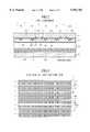
- FIG. 1is a perspective view illustrating the basic structure of a PDP 1 according to the present invention.
- the same reference numerals as used in FIG. 14are also used in FIG. 1 to denote corresponding or identical components, regardless of differences in shapes and materials. The same can be applied for the following drawings.
- the PDP 1, as well as the conventional PDP 90,is a surface discharge PDP having a three-electrode structure with a matrix display form that is called a reflection type.
- the external appearanceis derived from paired glass substrates 11 and 21, which face each other with an intervening discharge space 30 therebetween.
- the glass substrates 11 and 21are bonded by a seal frame layer (not shown) of a glass having a low-melting point that is formed along the edges of the facing substrate.
- a pair of linear display electrodes X and Y in parallelare arranged for each line L of a matrix display on the internal surface of the front glass substrate 11, for the generation of a surface discharge along the substrate surface.
- the line pitchis, for example, 660 ⁇ m.
- Each of the display electrodes X and Ycomprises a wide, linear transparent electrode 41 formed of ITO thin film and a narrow, linear bus electrode 42 formed of metal thin film having a multi-layer structure.
- the transparent electrode 41is 0.1 ⁇ m thick and 180 ⁇ m wide, while the bus electrode 42 is 1 ⁇ m thick and 60 ⁇ m wide.
- the bus electrode 42is an auxiliary electrode for acquiring appropriate conductivity, and is located at the edge of the transparent electrode 41 away from a surface discharge gap.
- a dielectric layer for (example PbO low-melting-point glass layer) 17 for AC drivingis formed to cover the display electrodes X and Y and separate them from the discharge space 30.
- a protective film 18 made of MgO (magnesium oxide) for exampleis deposited on the surface of the dielectric layer 17 by evaporation.
- the thickness of the dielectric layer 17is about 30 ⁇ m and the thickness of the protective film 18 is approximately 5000 ⁇ for example.
- the internal surface of the rear glass substrate 21is coated with an underlayer 22 of approximately 10 ⁇ m, which is ZnO low-melting-point glass for example.
- Address electrodes Aare arranged on the underlayer 22 at constant pitches (for example 220 ⁇ m), so that they intersect the paired display electrodes X and Y at a right angle.
- the address electrode Ais produced by annealing silver paste for example, and its thickness is about 10 ⁇ m.
- the underlayer 22prevents electromigration of the address electrodes A.
- the condition of wall electric charge accumulation on the dielectric layer 17is controlled by a discharge between the address electrodes A and the display electrodes Y.
- the address electrodesare also covered with a dielectric layer 24 that is formed of low-melting-point glass with the same composition for example as that of the underlayer 22.
- the dielectric layer 24 at the upper portions of the address electrodes Ais about 10 ⁇ m thick for example.
- barrier ribs 29which are about 150 ⁇ m high and linear in a plan view, are individually arranged between the address electrodes A.
- phosphors layers 28R, 28B and 28C(hereinafter referred to as the "phosphors layers 28," when distinguishing between colors is not especially required), for the three primary colors R (red), G (green) and B (blue) of a full-color display, are formed so as to cover the surface of the dielectric layer 24, including the upper portions of the address electrodes A, and the sides of the barrier ribs 29.
- These phosphors layers 28emit light when they are excited by the ultraviolet rays produced by the surface discharge.
- the discharge space 30is defined by the barrier ribs 29 for the units of light emitting areas along the lines (along the arrangement of pixels running parallel with the display electrodes X and Y), and the size of a gap between the discharge space 30 is also defined.
- the barrier ribs 29for the units of light emitting areas along the lines (along the arrangement of pixels running parallel with the display electrodes X and Y), and the size of a gap between the discharge space 30 is also defined.
- there are no barrier ribs for defining the discharge space 30 along the columns for a matrix display(along the arrangement direction of the paired display electrodes X and Y or the address lines direction).
- the size of a gap (the width of a reverse slit) for display lines L, along which the paired display electrodes X and Y are arrangedis set to from 100 to 400 ⁇ m, which is sufficiently large compared with the size of a surface discharge gap (the width of a discharge slit) of 50 ⁇ m for each display line L, the interference of a discharge does not occur between the lines L.
- a display pixel of the PDP 1comprises three unit light emitting areas (sub-pixels) adjacent each other in each line L.
- the luminous colors for all the lines L in the same columnare the same, and the phosphors layers 28R, 28B and 28C are so provided by screen printing that they are continuously arranged in each column along the address electrode. For this, screen printing provides excellent productivity.
- the arrangement of the continuous phosphors layers 28 along a columncan easily provide the uniform thickness of the phosphors layers 28 for the sub-pixels.
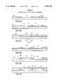
- FIG. 2is a cross sectional view of the essential portion of the PDP 1
- FIG. 3is a plan view of a light shielding film 45.
- a light shielding film 45 for blocking (shielding) a visible lightis formed for each reverse slit S2, so that the film 45 directly contacts the internal surface of the glass substrate 11.
- the shielding films 45are formed in patterns of belts that extend along the display lines, and are located to overlap the areas sandwiched between the display electrodes X and Y of the adjacent lines L.
- the light shielding films 45are separated from each other to constitute a striped shielding pattern for an entire display screen so that the phosphors layers 28 are hidden between the display lines L, and the contrast for a display is increased. Since the striped pattern along the display line L does not shift along the display lines L, unlike a matrix pattern surrounding the sub-pixels or pixels, it is easy to align and position the glass substrates 11 and 21 during the manufacturing of the PDP 1.
- the top portions of the barrier ribs 29have the same dark color as that of the light shielding films.
- a dark lattice patternis formed by intersecting the barrier ribs and the light shielding films, and the outline of each sub-pixel becomes clear.
- a black color agentsuch as chromium (Cr) is mixed with the material for the barrier ribs to provide uniformly dark barrier ribs.
- FIGS. 4A through 4Fare diagrams illustrating a method for manufacturing the front side portion of the PDP 1.
- the PDP 1is produced by providing predetermined components independently for the glass substrate 11 and the glass substrate 21, and by thereafter bonding together the glass substrates 11 and 21 around their circumferences while they are positioned facing each other.
- a dark colored insulating materialis deposited on the surface of the glass substrate 11 by sputtering to form an insulation film (not shown) having a surface reflectivity lower than that of the metal electrode 42.
- Chromium oxide (CrO) or silicon oxidecan be used as the insulation material. It is desirable that the thickness of the insulation film be 1 ⁇ m or less in order to reduce the step difference to the transparent electrodes 41.
- patterningis performed to the insulation film by photolithography using a first light exposing mask, and a plurality of the light shielding film stripes 45 described above are produced at one time (FIG. 4A).
- an ITO filmis deposited on the glass substrate 11, whereon the light shielding films 45 are formed, and patterning of the ITO film is performed by photolithography using a second light exposing mask.
- Transparent electrodes 41are thus formed so that they partially overlap the light shielding films 45 (FIG. 4B).
- a negative photosensitive material 61which is irreversibly solidified by exposure to ultraviolet rays, is coated on the resultant structure so that it covers the light shielding films 45 and the transparent electrodes 41.
- the photosensitive materialis fully exposed to the light from the reverse side of the glass substrate 11 (FIG. 4C). Then, the photosensitive material 61 is developed and forms a resist layer 62 which covers only an area between the light shielding films 45 (FIG. 4D).
- the metal electrodes 42having a multiple layer structure of, for example, nickel/copper/nickel, are formed on the exposed portions of the transparent electrodes 41 by selective plating (FIG. 4E).
- the resist layer 62is removed, and the dielectric layer 17 and the protective film 18 are deposited in order.
- the front portion of the PDP 1is thus produced (FIG. 4F).
- the number of required light exposing masksis two (FIGS. 4A and 4B), the same as is required by the fabrication process for the conventional PDP 90, and the number of alignment procedures for the exposing masks is one, also the same as in the conventional process.
- the light shielding films 45can be formed without deterioration of a yield due to a shift in alignment.
- FIG. 5is a cross sectional view of the essential portion of a PDP 2 according to a second embodiment of the present invention, i.e., showing the front portion of a discharge space.
- light shielding films 46having the same width as the reverse slit S2 are provided on the internal surface of a front glass substrate 11.
- the light shielding films 46are extended in a belt shape along the display line in a plan view, and constitute a striped light shielding pattern.
- paired display electrodes X and Yare formed on the glass substrate 11. And a black pigment, such as iron oxide or cobalt oxide, that has a heat resistance of 600° C. or higher is printed on the reverse slit area S2 to form the light shielding films 46. Low-melting-point glass is coated and annealed at 500 to 600° C. to produce the dielectric layer 17.
- the thickness of the light shielding films 46be less than the thickness of the individual display electrodes so as to acquire the flat surface of the dielectric layer 17. Further, it is desirable that the dielectric layer 17 be formed in two layers, and that annealing be performed for each layer. More specifically, a comparatively thin coat of low-melting-point glass paste is applied to the substrate and the glass paste is annealed to form a lower dielectric layer 17a. Then, another coat of the low-melting-point glass paste is applied to acquire a dielectric layer 17 having the required thickness, and the glass paste is annealed to produce an upper dielectric layer 17b.
- the lower dielectric layer 17awhich contacts the light shielding layers 46, is formed thin, the migration of a black pigment caused through the softening of the low-melting-point glass during the annealing, can be reduced, and the reduction in luminance due to the unwanted expansion of the light shielding films 46 can be prevented.
- the thickness of the lower dielectric layer 17ais so set that it is one tenth of or less than the width of the light shielding films 46, the migration of the pigment does not substantially appear.
- the unwanted expansion of the light shielding films 46can also be prevented by setting the temperature for annealing the lower dielectric layer 17a to a temperature that is lower than that for softening the low-melting-point glass.
- the lower dielectric layer 17a and the upper dielectric layer 17bcan be formed with the same thickness, or the upper dielectric layer 17b can be formed thinner than the lower dielectric layer 17a.
- FIG. 6is a cross sectional view of the essential portion of a PDP 3 according to a third embodiment of the present invention, and shows the structure of the front side portion of the discharge space.
- a light shielding film 47is provided for each reverse slit S2 in an intermediate portion in the direction of the thickness of a dielectric layer 17.
- the light shielding film 47, as well as the light shielding films 45 in FIG. 3,are extended in a belt shape along the display line in a plan view, and constitute a striped light shielding pattern.
- a width w47 of the light shielding film 47is greater than a width w2 of the reverse slit S2, and is smaller than the interval w22 between the edges, which are closer to the discharge slit S1 , of the metal electrodes 42 sandwiching the reverse slit S2.
- the plane size of the light shield film 47is so selected that it partially overlaps the metal electrodes 42.
- FIG. 7is a cross sectional view of the essential portions of a PDP 4 according to a fourth embodiment of the present invention.
- the light shielding films 45 shown in FIG. 2are formed between the X and Y electrodes 41 and 42 and the front glass substrate 10.
- light shielding films 49are formed inside the reverse slit S2 areas between the X and Y electrodes 41 and 42 so that they partially overlap the X and Y electrodes 41 and 42.
- This structureis similar to that in FIG. 2 because the light shielding films 49 are so formed that they completely hide the reverse slit S2 areas between the display lines L.
- the manufacturing process for this structurediffers from that in FIG. 2 in that the light shielding films 49 containing a black pigment are formed after the X and Y electrodes 41 and 42 are provided. This manufacturing process will be described later in detail.
- the light shielding films 49it is important for the light shielding films 49 to overlap the electrodes X and Y up to around the middle portions of the bus electrodes 42, which constitute a three-layer structure of Cr/Cu/Cr.
- the bus electrodes 42provide a higher conductivity for a highly resistant material for the transparent electrodes 41, the electrodes 42 themselves possess light shielding property.
- FIG. 8is a cross sectional view of the essential portion of a PDP 5 according to a fifth embodiment of the present invention.
- light shielding films 48are formed between X and Y electrodes 41 and 42 at a certain interval and without making contact with them.
- the distance of the non-display areas between the X and Y electrodes 41 and 42is 500 ⁇ m (using as an example a 42-inch PDP)
- the light shielding film 48is formed at an interval of about 20 ⁇ m from the electrodes 41 and 42.
- This structureis preferable from the view of the manufacturing process for it, even though the gap between the display line areas L is not completely closed. More specifically, as well as with the PDP 4 in FIG.
- the light shielding films 48can be formed after the X and Y electrodes 41 and 42 are provided. Moreover, the annealing of the light shielding films 48 can be performed in conjunction with the annealing process for the dielectric layer 17, made of a low-melting-point glass, that is formed on them. Since the light shielding films 48 do not contact the electrodes 41 and 42 in the annealing process at a high temperature, a stable process can be accomplished. This will be described later in detail.
- the width of the light shielding films 48is considerably smaller than the non-display area W22, there is sufficient space so that when the alignment (positioning) of the light shielding films 48 is performed, the films 48 can be easily formed not to overlap the display line areas L.
- FIGS. 9A through 9E and 10A through 10Care cross sectional views for explaining a method for respectively fabricating the PDPs of the second, fourth, and fifth embodiments, shown in FIGS. 5, 7 and 8.
- a transparent electrode layer 41is formed across the entire surface by sputtering.
- the transparent electrode layer 41is formed with a thickness of approximately 0.1 ⁇ m by using ITO. Then, in the common lithography procedure, the transparent electrode layer 41 is formed in a striped pattern to provide X and Y electrodes 41 having a width of about 180 ⁇ m.
- a metal layer 42 having a three-layer structure of Cr/Cu/Cris formed as a bus electrode layer of about 1 ⁇ m on the entire surface by sputtering.
- the common lithography procedureis performed to pattern the metal layer 42 to approximately 60 ⁇ m.
- the bus electrode 42is so formed that it is positioned at the end of the side opposite to the side of the electrode 41 faces each other closely.
- sputteringis performed on the glass substrate 11 after it is placed in a high vacuum chamber. Since a light shielding film containing a black pigment, etc., is not formed on the glass substrate 11, the sputtering under a high vacuum can be stably performed.
- a photoresist layer 71 containing a black pigmentis formed by screen printing.
- the black pigmentis oxide of manganese (Mn), iron (Fe), or Copper (Cu), for example.
- Such a pigmentis mixed in a photoresist including photosensitive material.
- a pigment dispersion photoresistproduct name: CFPR BK of Tokyo Ohka Kogyo Co., Ltd. is used.
- the resultant structureis exposed to light through a predetermined mask pattern, and developed. Then, baking (drying) is performed on the structure for two to five minutes in a dry atmosphere at 120° C. to 200° C., for example, to form the light shielding films 49.
- the light shielding films 49are patterned to overlap the X and Y electrodes 41 and 42.
- the light shielding films 48can be formed separately from the X and Y electrodes 41 and 42, as is shown in FIG. 9E. This structure corresponds to that of the PDP 5 shown in FIG. 8. Similarly, the light shielding films 46 can be formed as are shown for the structure in FIG. 5.
- a photosensitive resist of a polymer organic materialis used for the light shielding films 49 and 48. If, prior to the formation of the electrodes 41 the light shielding films are formed and annealed for stability, the contact of the electrodes 41 may be deteriorated due to an uneven surface of the film. From this point of view, the process in FIG. 9 is an effective one.
- FIGS. 10A through 10Care cross sectional views of a method for forming a dielectric layer 17 and an MgO protection layer 18 on light shielding films. An explanation will be given for this example by employing the light shielding films 48, shown in FIGS. 8 and 9E, that are formed separately from the electrodes 41 and 42.
- annealing of the light shielding films 48is also performed together with the procedure for annealing the dielectric layer 17.
- a low-melting-point glass paste containing lead oxide (PbO) as the main elementis printed on the surface of the substrate, and is then annealed.
- This processinvolves at least two procedures: the printing and the annealing of the lower dielectric layer 17a and the upper dielectric layer 17b.
- a compositionis selected for which the viscosity is not decreased in the annealing atmosphere and which does not easily react with the ITO of the transparent electrodes 41 and the copper (Cu) of the bus electrodes 42.
- Such a composition materialis, for example, a glass paste that comprises PbO/SiO 2 /B 2 O 3 /ZnO, and that contains a comparatively large amount of SiO 2 .
- a compositionis selected for which the viscosity is adequately decreased in the annealing atmosphere and the surface is flattened.
- a glass pastewhich comprises PbO/SiO 2 /B 2 O 3 /ZnO and contains a comparatively small amount of SiO 2 is selected.
- the surface of the glass substrate 11is printed by a glass paste, which comprises PbO/SiO 2 /B 2 O 3 /ZnO and contains a comparatively large amount of SiO 2 .
- the substrate 11is then annealed for about 60 minutes in a dry atmosphere at 580° C. to 590° C.
- the viscosity of the glass pasteis not much decreased at the annealing temperature, and the paste does not easily react with the ITO of the transparent electrodes 41 and the copper (Cu) of the bus electrodes 42.
- the glass pasteis annealed at the same time as the light shielding films 48. Therefore, a savings in the time and labor required for the annealing process can be realized, as compared with the example wherein the light shielding films 48 are formed prior to the electrodes 41 and 42.
- the upper dielectric layer 17bis formed.
- the substrateis printed by using a glass paste and is annealed for about 60 minutes in a dry atmosphere at 580° C. to 590° C.
- the preferable glass pasteis one that comprises PbO/SiO 2 /B 2 O 3 /ZnO and contains a comparatively small amount of SiO 2 , as is described above. As a result, the dielectric layer 17 having a flat surface is formed.
- a thick layer of low-melting-point glass film for sealingis formed around the edges of the glass substrate 11 (not shown), and then, as is shown in FIG. 10C, the MgO film 18 is formed as a protective film by evaporation.
- the light shielding films 48are formed separately from the electrodes 41 and 42 in the process shown in FIG. 10, as previously described, the light shielding films may contact the electrodes 41 as in the PDPs 2 and 4 shown in FIGS. 5 and 7. Though the reason is still not well understood, when a substrate on which light shielding films are in contact with electrodes 41 and 42 is placed in an annealing atmosphere at a temperature close to 600° C., the light shielding films may be turned brown, and to prevent this, it may be effective for the light shielding films to be separated from the electrodes 41 and 42 in the same manner as for the light shielding films 48. The separation interval in this case is called a color change prevention gap for convenience sake.
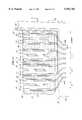
- FIG. 11is a plan view of a PDP wherein light shielding films 48 are formed in the periphery outside a display area of the panel.
- FIG. 12is a cross sectional view of the portion taken along the line XX-YY in FIG. 11. As is described above, the contrast of a display is increased by forming light shielding films 48 between the X and Y electrodes in the areas between the display lines L1, L2 and L3. In FIG. 11, the light shielding films 48 are also formed in a peripheral area.
- dummy X and Y electrodes DX and DYare formed at the peripheral portions of paired X and Y electrodes X1, Y1, X2, Y2, X3 and Y3, which commonly serve as display electrodes. Wall charges not required for display are prevented from being accumulated by frequently performing discharges between the dummy electrodes DX and DY also.
- the discharges performed in the peripheral area and the exposure of the phosphors layercause contrast in a display area to be deteriorated. Therefore, as is shown in FIG. 11, the light shielding films 48 are formed on the dummy electrodes DX and DY (indicated as Dummy in FIG.
- the EX described by the chain linesis a display screen frame on the surface of the panel, and a sealing member 50 is formed at a position on the frame EX to seal the glass substrates.
- the front glass substrate 11 and the sealing member 50 formed on the MgO film 18are shown, while a rear glass substrate is omitted.
- the leads 42R of the bus electrodes 42are connected to an external controller via a flexible cable (not shown). Therefore, the two glass substrates are sealed together by the sealing member 50 at the portion of the leads 42R of the bus electrodes 42.
- the specific oxide agents that were used in this mannerare NaNO 3 , BaO 2 , etc. And as a result, it was confirmed that no color change occurred, even when the annealing process was completed.
- the light shielding filmscan increase the contrast for a display in the PDP by not leaking light to the exterior from inside the PDP.
- black colorbecause of the black color, external light is regularly reflected from the phase boundary between the light shielding films 48 and the glass substrate 11, and as a mirror image due to this regular reflection appears, it is sometimes difficult to look at the display screen.
- the regular reflection between the paired display electrodesoccurs on the surface of the address electrodes at the back substrate.
- a low-melting-point glass powderis mixed in the material for the light shielding films.
- the low-melting-point glass powderis the same material as the dielectric layer 17, for example, and is contained about 50% in the organic photosensitive resist 71.
- the organic photosensitive resist 71therefore, contains a black pigment and a low-melting-point glass powder.
- the regular reflection of external lightoccurs on the outer surface of the front glass substrate 11, the refractive index of the light shielding film 48 is close to that of the glass substrate 11 at their phase boundary, and accordingly, the reflectivity is reduced to about half. Further, light is absorbed by the black pigment contained in the light shielding films 48, and accordingly, reflected light is also reduced. Therefore, the regular reflection at the display screen is reduced as a whole, and the unclear display due to mirror imaging is improved.
- the light shielding filmsare formed to increase the contrast for a display screen.
- an oxide agentis mixed in the organic photosensitive resist 71 to prevent a color change from occurring during the annealing process, and the low-melting-point glass is mixed in to prevent regular reflection.
- a method for preventing the change in the color of the light shielding filmsproposed is a method wherein the display electrodes are coated with a thin insulation film, such as SiO 2 film, to keep the light shielding films from contacting the display electrodes.
- a thin insulation filmsuch as SiO 2 film
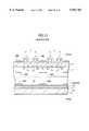
- FIG. 13is a cross sectional view of a modification of the PDP, showing a front glass substrate 11 and a rear glass substrate 12.
- light shielding films 48light shielding films 48A are formed on the outer surface of the front substrate 11 in the areas between the display lines L; light shielding films 48B are formed inside a dielectric layer 17; and light shielding films 48C are formed above a phosphors film 24 on the rear glass substrate 21.
- the present inventioncan also be applied for a transmission PDP in which a phosphors layer 28 is formed on a front glass substrate 11. And light shielding films may be formed on the outer surface of the glass substrate 11. It should be noted that in this case, an alignment process between the glass substrates is required.
- non-luminous areas between display linescan be shielded so they are not noticeable, and the contrast for a display can be increased.
- reflection of external light at the surface of a phosphors layercan be prevented, and a display having high contrast can be provided.
- reflection of external lightcan be prevented not only at the area between the display line but also at the surface of a metal electrode, and a display having high contrast can be achieved.
- light shielding filmscan be formed without increasing the number of mask alignment processes for patterning, a high yield can be maintained and the contrast for a display can be increased.
- light shielding films and a dielectric layercan be formed and annealed together, and a comparatively stable process can be performed.
Landscapes
- Engineering & Computer Science (AREA)
- Physics & Mathematics (AREA)
- Plasma & Fusion (AREA)
- Manufacturing & Machinery (AREA)
- Electromagnetism (AREA)
- Gas-Filled Discharge Tubes (AREA)
Abstract
Description
Claims (28)
Priority Applications (2)
| Application Number | Priority Date | Filing Date | Title |
|---|---|---|---|
| US09/290,222US6200182B1 (en) | 1995-08-25 | 1999-04-13 | Method for manufacturing a surface discharge plasma display panel |
| US09/569,472US6297590B1 (en) | 1995-08-25 | 2000-05-12 | Surface discharge plasma display panel |
Applications Claiming Priority (4)
| Application Number | Priority Date | Filing Date | Title |
|---|---|---|---|
| JP7-217136 | 1995-08-25 | ||
| JP21713695 | 1995-08-25 | ||
| JP19183796AJP3163563B2 (en) | 1995-08-25 | 1996-07-22 | Surface discharge type plasma display panel and manufacturing method thereof |
| JP8-191837 | 1996-07-22 |
Related Child Applications (1)
| Application Number | Title | Priority Date | Filing Date |
|---|---|---|---|
| US09/290,222DivisionUS6200182B1 (en) | 1995-08-25 | 1999-04-13 | Method for manufacturing a surface discharge plasma display panel |
Publications (1)
| Publication Number | Publication Date |
|---|---|
| US5952782Atrue US5952782A (en) | 1999-09-14 |
Family
ID=26506928
Family Applications (3)
| Application Number | Title | Priority Date | Filing Date |
|---|---|---|---|
| US08/689,591Expired - LifetimeUS5952782A (en) | 1995-08-25 | 1996-08-12 | Surface discharge plasma display including light shielding film between adjacent electrode pairs |
| US09/290,222Expired - LifetimeUS6200182B1 (en) | 1995-08-25 | 1999-04-13 | Method for manufacturing a surface discharge plasma display panel |
| US09/569,472Expired - LifetimeUS6297590B1 (en) | 1995-08-25 | 2000-05-12 | Surface discharge plasma display panel |
Family Applications After (2)
| Application Number | Title | Priority Date | Filing Date |
|---|---|---|---|
| US09/290,222Expired - LifetimeUS6200182B1 (en) | 1995-08-25 | 1999-04-13 | Method for manufacturing a surface discharge plasma display panel |
| US09/569,472Expired - LifetimeUS6297590B1 (en) | 1995-08-25 | 2000-05-12 | Surface discharge plasma display panel |
Country Status (7)
| Country | Link |
|---|---|
| US (3) | US5952782A (en) |
| EP (3) | EP2226829B1 (en) |
| JP (1) | JP3163563B2 (en) |
| KR (2) | KR100349735B1 (en) |
| CN (1) | CN1306550C (en) |
| DE (2) | DE69621724T2 (en) |
| TW (1) | TW400512B (en) |
Cited By (353)
| Publication number | Priority date | Publication date | Assignee | Title |
|---|---|---|---|---|
| US6031329A (en)* | 1997-03-31 | 2000-02-29 | Mitsubishi Denki Kabushiki Kaisha | Plasma display panel |
| US6081306A (en)* | 1997-03-26 | 2000-06-27 | Mitsubishi Denki Kabushiki Kaisha | Manufacturing method of panel display and its apparatus |
| US6137226A (en)* | 1997-03-14 | 2000-10-24 | Mitsubishi Denki Kabushiki Kaisha | Plasma display panel |
| US6211614B1 (en)* | 1997-08-13 | 2001-04-03 | Fujitsu Limited | Electrode structure of an AC type plasma display panel |
| US6215241B1 (en)* | 1998-05-29 | 2001-04-10 | Candescent Technologies Corporation | Flat panel display with encapsulated matrix structure |
| US6222316B1 (en)* | 1997-06-19 | 2001-04-24 | Lg Electronics Inc. | Barrier structure of plasma display panel |
| US6252353B1 (en)* | 1997-12-17 | 2001-06-26 | Lg Electronics Inc. | Color plasma display panel |
| US6255780B1 (en)* | 1998-04-21 | 2001-07-03 | Pioneer Electronic Corporation | Plasma display panel |
| US6262532B1 (en)* | 1998-03-31 | 2001-07-17 | Samsung Display Devices Co., Ltd. | Plasma display device with electrically floated auxiliary electrodes |
| US6285128B1 (en)* | 1997-12-19 | 2001-09-04 | Pioneer Electronic Corporation | Surface discharge type plasma display panel |
| US6297590B1 (en)* | 1995-08-25 | 2001-10-02 | Fujitsu Limited | Surface discharge plasma display panel |
| US6333597B1 (en)* | 1997-11-28 | 2001-12-25 | Pioneer Electronic Corporation | Plasma display panel with color filter layers |
| US6339288B1 (en)* | 1998-02-25 | 2002-01-15 | Toppan Printing Co., Ltd. | Circuit board for organic electroluminescent panel, method of manufacture, and electroluminescent panel |
| US6351066B1 (en)* | 1997-10-14 | 2002-02-26 | Matsushita Electric Industrial Co., Ltd. | Organic electroluminescence element having an insulating bulkhead having an overhang portion |
| US6376987B1 (en)* | 1998-04-14 | 2002-04-23 | Pioneer Electronics Corporation | AC-driving plasma display panel of surface-discharge type |
| US20020050791A1 (en)* | 2000-10-31 | 2002-05-02 | Lee Won-Tae | Plasma display panel |
| US6414656B1 (en)* | 1999-03-02 | 2002-07-02 | Samsung Sdi Co., Ltd. | Plasma display panel having auxiliary electrode and method for driving the same |
| US6417620B1 (en)* | 1998-02-02 | 2002-07-09 | Mitsubishi Denki Kabushiki Kaisha | Surface discharge plasma display panel having two-dimensional black stripes of specific size and shape |
| US6420830B1 (en)* | 1998-01-26 | 2002-07-16 | Lg Electronics Inc. | Plasma display panel having three discharge sustain electrodes per two pixels |
| US6429586B1 (en)* | 1998-02-13 | 2002-08-06 | Hitachi, Ltd. | Gas discharge display panel and gas discharge display device having electrodes formed by laser processing |
| US20020105270A1 (en)* | 2001-01-16 | 2002-08-08 | Yoshitaka Terao | Plasma display and manufacturing method thereof |
| US6433489B1 (en)* | 1998-04-28 | 2002-08-13 | Matsushita Electric Industrial Co., Ltd. | Plasma display panel and method for manufacturing the same |
| US20020130621A1 (en)* | 2001-03-13 | 2002-09-19 | Jeong Jae-Seok | Plasma display panel |
| US6465956B1 (en)* | 1998-12-28 | 2002-10-15 | Pioneer Corporation | Plasma display panel |
| US20020172613A1 (en)* | 2000-06-30 | 2002-11-21 | Kunio Fukuda | Fe-cr-al based alloy foil and method for producing the same |
| US6504312B2 (en)* | 2000-03-23 | 2003-01-07 | Planar Systems, Inc. | AMEL device with improved optical properties |
| US6514111B2 (en)* | 1998-07-09 | 2003-02-04 | Fujitsu Limited | Plasma display panel having a dielectric layer of a reduced thickness in a sealing portion |
| US20030034728A1 (en)* | 2001-08-16 | 2003-02-20 | Lg Electronics Inc. | Plasma display panel |
| US6525470B1 (en)* | 1998-04-14 | 2003-02-25 | Pioneer Electronic Corporation | Plasma display panel having a particular dielectric structure |
| US20030062836A1 (en)* | 2001-09-28 | 2003-04-03 | Lg Electronics Inc. | Plasma display panel |
| US20030062835A1 (en)* | 2001-09-28 | 2003-04-03 | Lg Electronics Inc. | Plasma display panel |
| US6580216B1 (en)* | 1999-08-31 | 2003-06-17 | Au Optronics Corp. | High contrast PDP and a method for making the same |
| US6603264B1 (en)* | 1998-03-31 | 2003-08-05 | Matsushita Electric Industrial Of Co., Ltd. | Plasma display panel having a non-reflective glass layer |
| US6603265B2 (en)* | 2000-01-25 | 2003-08-05 | Lg Electronics Inc. | Plasma display panel having trigger electrodes |
| US20030151363A1 (en)* | 1999-03-31 | 2003-08-14 | Samsung Sdi Co., Ltd. | Plasma display device and method of manufacturing dielectric layer having portion where electrical field is concentrated |
| US6614183B2 (en)* | 2000-02-29 | 2003-09-02 | Pioneer Corporation | Plasma display panel and method of manufacturing the same |
| US6624799B1 (en)* | 1999-11-18 | 2003-09-23 | Lg Electronics Inc. | Radio frequency plasma display panel |
| US6628075B1 (en)* | 1999-09-28 | 2003-09-30 | Lg Electronics, Inc. | Plasma display panel with first and second inner and outer electrodes |
| US6650051B1 (en)* | 1999-02-25 | 2003-11-18 | Samsung Sdi Co., Ltd. | Plasma display panel |
| US6650053B2 (en)* | 2000-01-26 | 2003-11-18 | Matsushita Electric Industrial Co., Ltd. | Surface-discharge type display device with reduced power consumption and method of making display device |
| US20030218432A1 (en)* | 2002-05-24 | 2003-11-27 | Yoo-Jin Song | Automatic power control (APC) method and device of plasma display panel (PDP) and PDP device having the APC device |
| US6674236B1 (en)* | 1999-05-20 | 2004-01-06 | Fujitsu Limited | Gas-discharge display panel and process for manufacturing the display panel |
| US20040008162A1 (en)* | 2002-07-12 | 2004-01-15 | Jin-Sung Kim | Method of driving 3-electrode plasma display apparatus to minimize addressing power |
| US20040061669A1 (en)* | 2002-07-23 | 2004-04-01 | Kang Kyoung-Ho | Plasma display panel and method for driving the same |
| US6716078B1 (en)* | 2000-07-27 | 2004-04-06 | Motorola Inc. | Field emission display and method of manufacture |
| US20040075625A1 (en)* | 2002-07-08 | 2004-04-22 | Joon-Koo Kim | Apparatus and method for driving plasma display panel to enhance display of gray scale and color |
| US6734626B2 (en)* | 2000-07-24 | 2004-05-11 | Nec Corporation | Plasma display panel and fabrication method thereof |
| US20040091672A1 (en)* | 2002-11-05 | 2004-05-13 | Jung-Keun Ahn | Plasma display panel |
| US20040090170A1 (en)* | 2002-11-06 | 2004-05-13 | Jun-Kyu Cha | Filter for plasma display panel and method of manufacturing the same |
| US20040113553A1 (en)* | 2002-12-17 | 2004-06-17 | Cha-Keun Yoon | Plasma display panel |
| US20040119909A1 (en)* | 2002-12-18 | 2004-06-24 | Che-Chih Chang | Backlight module |
| US20040130265A1 (en)* | 2002-08-02 | 2004-07-08 | Yoshitaka Terao | Plasma display panel and manufacturing method thereof |
| US20040135509A1 (en)* | 2002-12-27 | 2004-07-15 | Jae-Ik Kwon | Plasma display panel |
| US20040135508A1 (en)* | 2003-01-02 | 2004-07-15 | Jae-Ik Kwon | Plasma display panel |
| US20040150340A1 (en)* | 2002-12-31 | 2004-08-05 | Seung-Hyun Son | Plasma display panel including sustain electrodes having double gap and method of manufacturing the panel |
| US20040164677A1 (en)* | 2003-02-21 | 2004-08-26 | Tae-Ho Lee | Plasma display panel and method of manufacture thereof |
| US20040201350A1 (en)* | 2003-01-02 | 2004-10-14 | Jae-Ik Kwon | Plasma display panel |
| US20040212554A1 (en)* | 2003-04-28 | 2004-10-28 | Ki-Jung Kim | Plasma display device that efficiently and effectively draws heat out from a functioning plasma display panel |
| US20040232843A1 (en)* | 2003-05-21 | 2004-11-25 | Kim Gi-Young | Plasma display panel and method of forming address electrodes thereof |
| US20040239249A1 (en)* | 2001-11-13 | 2004-12-02 | Kang Seok Dong | Plasma display panel |
| US20040257307A1 (en)* | 2003-06-23 | 2004-12-23 | Sung-Won Bae | Plasma display device |
| US20040256989A1 (en)* | 2003-06-19 | 2004-12-23 | Woo-Tae Kim | Plasma display panel |
| US20040263078A1 (en)* | 2003-06-25 | 2004-12-30 | Seok-Gyun Woo | Plasma display panel |
| US20050001551A1 (en)* | 2003-07-04 | 2005-01-06 | Woo-Tae Kim | Plasma display panel |
| US6841928B2 (en)* | 2000-04-29 | 2005-01-11 | Samsung Sdi Co., Ltd. | Base panel having partition and plasma display device utilizing the same |
| US20050017638A1 (en)* | 2003-07-22 | 2005-01-27 | Woo-Tae Kim | Plasma display device |
| US20050017637A1 (en)* | 2003-07-22 | 2005-01-27 | Kyoung-Doo Kang | Plasma display panel |
| US20050017640A1 (en)* | 2003-07-26 | 2005-01-27 | Lg Electronics Inc. | Plasma display panel and fabrication method thereof |
| US20050023977A1 (en)* | 2003-07-29 | 2005-02-03 | Jeong-Chull Ahn | Plasma display panel |
| US20050029939A1 (en)* | 2003-07-04 | 2005-02-10 | Seok-Gyun Woo | Plasma display panel |
| US20050035931A1 (en)* | 2003-08-12 | 2005-02-17 | Hun-Suk Yoo | Plasma display panel driving method and plasma display device |
| US20050035713A1 (en)* | 2003-08-13 | 2005-02-17 | Sung-Hune Yoo | Plasma display panel |
| US20050040767A1 (en)* | 2003-08-18 | 2005-02-24 | Sung-Hune Yoo | Plasma display panel using color filters to improve contrast |
| US20050046618A1 (en)* | 2003-09-01 | 2005-03-03 | Sok-San Kim | Plasma display module with improved heat dissipation characteristics |
| US20050046352A1 (en)* | 2003-08-26 | 2005-03-03 | Cha-Keun Yoon | Plasma display panel |
| US20050046353A1 (en)* | 2003-09-02 | 2005-03-03 | Jae-Ik Kwon | Address electrode design in a plasma display panel |
| US20050052358A1 (en)* | 2003-09-09 | 2005-03-10 | In-Soo Cho | Heat dissipating sheet and plasma display device including the same |
| US20050052138A1 (en)* | 2003-09-08 | 2005-03-10 | Tae-Joung Kweon | Plasma display panel and method of manufacturing the same resulting in improved contrast and improved chromaticity |
| US20050052359A1 (en)* | 2003-09-04 | 2005-03-10 | Jae-Ik Kwon | Plasma display panel |
| US20050052137A1 (en)* | 2003-09-04 | 2005-03-10 | Jae-Ik Kwon | Plasma display panel |
| US20050057444A1 (en)* | 2003-09-01 | 2005-03-17 | Ji-Sung Ko | Plasma display panel |
| US20050062418A1 (en)* | 2003-09-04 | 2005-03-24 | Kang Tae-Kyoung | Plasma display panel |
| US6873106B2 (en)* | 2000-06-01 | 2005-03-29 | Pioneer Corporation | Plasma display panel that inhibits false discharge |
| US20050068265A1 (en)* | 2003-09-26 | 2005-03-31 | Mi-Young Joo | Method and apparatus to automatically control power of address data for plasma display panel, and plasma display panel including the apparatus |
| US20050067957A1 (en)* | 2002-09-27 | 2005-03-31 | Moon Cheol-Hee | Plasma display panel |
| US20050073477A1 (en)* | 2003-10-01 | 2005-04-07 | Sung-Hune Yoo | Plasma display panel (PDP) |
| US20050073484A1 (en)* | 2003-10-01 | 2005-04-07 | Kim Se-Woong | Driving apparatus of plasma display panel and method for displaying pictures on plasma display panel |
| US20050078063A1 (en)* | 2003-10-09 | 2005-04-14 | Yong-Seok Chi | Plasma display panel and driving method thereof |
| US20050077823A1 (en)* | 2003-10-09 | 2005-04-14 | Song Young-Hwa | Plasma display panel |
| US20050077836A1 (en)* | 2003-10-14 | 2005-04-14 | Kwang-Ho Jin | Discharge display apparatus minimizing addressing power and method of driving the same |
| US20050077835A1 (en)* | 2003-10-08 | 2005-04-14 | Ki-Jung Kim | Thermal conductive medium for display device, method of fabricating the same, and plasma display panel assembly using the same |
| US20050083254A1 (en)* | 2003-10-21 | 2005-04-21 | Jang Tae-Woong | Plasma display panel |
| US20050083258A1 (en)* | 2003-10-21 | 2005-04-21 | Im-Su Choi | Method of expressing gray level of high load image and plasma display panel driving apparatus using the method |
| US20050082979A1 (en)* | 2003-10-16 | 2005-04-21 | Eun-Young Jung | Plasma display panel |
| US20050083265A1 (en)* | 2003-10-16 | 2005-04-21 | Mi-Young Joo | Plasma display panel device, white linearity control device and control method thereof |
| US20050088096A1 (en)* | 2003-10-28 | 2005-04-28 | Sung-Hune Yoo | Plasma display panel (PDP) with multiple dielectric layers |
| US20050088097A1 (en)* | 2003-10-24 | 2005-04-28 | Sung-Won Bae | Plasma display device |
| US20050088071A1 (en)* | 2003-10-23 | 2005-04-28 | Joong-Ha Ahn | Plasma display apparatus having heat dissipating structure for driver integrated circuit |
| US20050088092A1 (en)* | 2003-10-17 | 2005-04-28 | Myoung-Kon Kim | Plasma display apparatus |
| US20050093447A1 (en)* | 2003-10-31 | 2005-05-05 | Byung-Soo Jeon | Plasma display panel |
| US20050093446A1 (en)* | 2003-10-09 | 2005-05-05 | Chong-Gi Hong | Plasma display panel and method of manufacturing back panel thereof |
| US20050093451A1 (en)* | 2003-10-30 | 2005-05-05 | Tae-Joung Kweon | Method of forming a dielectric film and plasma display panel using the dielectric film |
| US20050093444A1 (en)* | 2003-10-29 | 2005-05-05 | Seok-Gyun Woo | Plasma display panel |
| US20050093448A1 (en)* | 2003-10-31 | 2005-05-05 | Moon Cheol-Hee | Plasma display panel provided with an improved electrode |
| US20050099126A1 (en)* | 2003-11-11 | 2005-05-12 | Young-Mo Kim | Plasma display panel with discharge cells having curved concave-shaped walls |
| US20050099122A1 (en)* | 2003-11-07 | 2005-05-12 | Wan Shiang W. | Plasma display panel structure |
| US20050099106A1 (en)* | 2003-11-08 | 2005-05-12 | Ki-Jung Kim | Plasma display apparatus |
| US20050104518A1 (en)* | 2003-10-21 | 2005-05-19 | Chong-Gi Hong | Plasma display panel having high brightness and high contrast |
| US20050104520A1 (en)* | 2003-11-17 | 2005-05-19 | Chong-Gi Hong | Plasma display panel and method of manufacturing the plasma display panel |
| US20050104519A1 (en)* | 2003-11-13 | 2005-05-19 | Byung-Soo Jeon | Plasma display panel |
| US20050110408A1 (en)* | 2003-11-26 | 2005-05-26 | Jang Sang-Hun | Plasma display panel |
| US20050110407A1 (en)* | 2003-11-26 | 2005-05-26 | Chun-Soo Kim | Plasma display device |
| US20050111175A1 (en)* | 2003-10-16 | 2005-05-26 | Dae-Gyu Kim | Plasma display module |
| US20050110707A1 (en)* | 2003-11-22 | 2005-05-26 | Im-Su Choi | Method and apparatus for driving discharge display panel to improve linearity of gray-scale |
| US20050110709A1 (en)* | 2003-11-24 | 2005-05-26 | Lee Joo-Yul | Driving a plasma display panel (PDP) |
| US20050117304A1 (en)* | 2003-11-28 | 2005-06-02 | Ki-Jung Kim | Device having improved heat dissipation |
| US20050116648A1 (en)* | 2003-11-29 | 2005-06-02 | Byung-Kwan Song | Plasma display panel and method for manufacturing the same |
| US20050116643A1 (en)* | 2003-11-27 | 2005-06-02 | Yi-Hyun Chang | Plasma display panel (PDP) |
| US20050116640A1 (en)* | 2003-10-16 | 2005-06-02 | Sung-Hune Yoo | Plasma display panel |
| US20050116642A1 (en)* | 2003-11-29 | 2005-06-02 | Moon Cheol-Hee | Plasma display panel and method of manufacturing the same |
| US20050116641A1 (en)* | 2003-11-29 | 2005-06-02 | Seung-Uk Kwon | Green phosphor for plasma display panel (PDP) |
| US20050116646A1 (en)* | 2003-11-29 | 2005-06-02 | Hun-Suk Yoo | Plasma display panel |
| US20050134176A1 (en)* | 2003-11-29 | 2005-06-23 | Jae-Ik Kwon | Plasma display panel |
| US20050140581A1 (en)* | 2003-11-29 | 2005-06-30 | Kyoung-Doo Kang | Method of driving plasma display panel (PDP) |
| US20050140580A1 (en)* | 2003-11-24 | 2005-06-30 | Joon-Suk Baik | Method of driving plasma display panel |
| US20050140579A1 (en)* | 2003-09-08 | 2005-06-30 | Sung-Hune Yoo | Structure for a plasma display panel that reduces capacitance between electrodes |
| US20050148151A1 (en)* | 2003-11-29 | 2005-07-07 | Jong-Sang Lee | Plasma display panel and manufacturing method thereof |
| US20050156525A1 (en)* | 2004-01-17 | 2005-07-21 | Kyu-Nam Joo | Filter assembly, method of manufacturing the same, and plasma display panel using the same |
| US20050162062A1 (en)* | 2004-01-26 | 2005-07-28 | Sung-Yong Lee | Green phosphor for plasma display panel and plasma display panel comprising the same |
| US20050168405A1 (en)* | 2004-01-29 | 2005-08-04 | Jun-Young Lee | Method of driving plasma display panel and plasma display device |
| US20050174301A1 (en)* | 2004-02-10 | 2005-08-11 | Sok-San Kim | Plasma display module |
| US20050179384A1 (en)* | 2004-02-18 | 2005-08-18 | Jae-Ik Kwon | Plasma display panel (PDP) |
| US20050184663A1 (en)* | 2004-02-25 | 2005-08-25 | Moon Cheol-Hee | Plasma display apparatus |
| US20050184664A1 (en)* | 2004-02-21 | 2005-08-25 | Kang Tae-Kyoung | Plasma display device |
| US20050190120A1 (en)* | 2004-02-26 | 2005-09-01 | Hun-Suk Yoo | Display panel driving method |
| US20050194900A1 (en)* | 2004-03-04 | 2005-09-08 | Hyouk Kim | Plasma display apparatus |
| US20050212425A1 (en)* | 2004-03-26 | 2005-09-29 | Hun-Suk Yoo | Plasma display panel |
| US20050213010A1 (en)* | 2004-03-26 | 2005-09-29 | Jae-Ik Kwon | Plasma display panel |
| US20050212423A1 (en)* | 2004-03-24 | 2005-09-29 | Jae-Ik Kwon | Plasma display panel |
| US20050212424A1 (en)* | 2004-03-25 | 2005-09-29 | Jae-Ik Kwon | Plasma display panel having electromagnetic wave shielding layer |
| US20050225243A1 (en)* | 2004-04-08 | 2005-10-13 | Yoo Min-Sun | Plasma display panel |
| US20050225245A1 (en)* | 2004-04-09 | 2005-10-13 | Seung-Beom Seo | Plasma display panel |
| US20050225241A1 (en)* | 2004-04-09 | 2005-10-13 | Seok-Gyun Woo | Plasma display panel |
| US20050225504A1 (en)* | 2004-04-12 | 2005-10-13 | Sang-Chul Kim | Plasma display panel (PDP) and method of driving PDP |
| US20050225244A1 (en)* | 2004-04-09 | 2005-10-13 | Jeong-Chul Ahn | Plasma display panel |
| US20050225242A1 (en)* | 2004-04-13 | 2005-10-13 | Seok-Gyun Woo | Plasma display panel (PDP) |
| US20050231112A1 (en)* | 2004-04-19 | 2005-10-20 | Seok-Gyun Woo | Plasma display panel and method of manufacturing the same |
| US20050231111A1 (en)* | 2004-04-20 | 2005-10-20 | Seok-Gyun Woo | Plasma display panel |
| US20050231113A1 (en)* | 2004-04-19 | 2005-10-20 | Kyoung-Doo Kang | Plasma display panel |
| US20050231109A1 (en)* | 2004-04-20 | 2005-10-20 | Hun-Suk Yoo | Plasma display panel (PDP) having electromagnetic wave shielding electrodes |
| US20050231115A1 (en)* | 2004-04-16 | 2005-10-20 | Jae-Ik Kwon | Plasma display panel |
| US20050231110A1 (en)* | 2004-04-19 | 2005-10-20 | Seok-Gyun Woo | Plasma Display Panel (PDP) |
| US20050231116A1 (en)* | 2004-04-20 | 2005-10-20 | Hun-Suk Yoo | High efficiency plasma display panel (PDP) |
| US20050236990A1 (en)* | 2004-04-27 | 2005-10-27 | Woo-Tae Kim | Plasma display panel |
| US20050236986A1 (en)* | 2004-04-27 | 2005-10-27 | Jae-Ik Kwon | Plasma display panel (PDP) |
| US20050236988A1 (en)* | 2004-04-12 | 2005-10-27 | Jae-Ik Kwon | Plasma display panel |
| US20050243026A1 (en)* | 2004-04-29 | 2005-11-03 | Tae-Seong Kim | Plasma display panel driving method and plasma display |
| US20050243106A1 (en)* | 2004-04-29 | 2005-11-03 | Sung-Won Bae | Plasma display apparatus |
| US20050242683A1 (en)* | 2004-04-30 | 2005-11-03 | Johnson Electric S.A. | Brush assembly |
| US20050242722A1 (en)* | 2004-05-01 | 2005-11-03 | Hun-Suk Yoo | Plasma display panel |
| US20050242724A1 (en)* | 2004-04-28 | 2005-11-03 | Woo-Tae Kim | Plasma display panel |
| US20050242729A1 (en)* | 2004-04-28 | 2005-11-03 | Tae-Joung Kweon | Plasma display panel |
| US20050242723A1 (en)* | 2004-05-01 | 2005-11-03 | Hun-Suk Yoo | Plasma display panel |
| US20050248273A1 (en)* | 2004-05-07 | 2005-11-10 | Tae-Joung Kweon | Plasma display panel |
| US20050253516A1 (en)* | 2004-05-12 | 2005-11-17 | Jae-Ik Kwon | Plasma display panel |
| US20050259045A1 (en)* | 2004-05-21 | 2005-11-24 | Seung-Beom Seo | Plasma display panel (PDP) |
| US20050259048A1 (en)* | 2004-05-24 | 2005-11-24 | Min Hur | Plasma display panel and a drive method therefor |
| US20050258751A1 (en)* | 2004-05-24 | 2005-11-24 | Kang Tae-Kyoung | Plasma display panel |
| US20050258747A1 (en)* | 2004-05-21 | 2005-11-24 | Su-Bin Song | Plasma display panel (PDP) |
| US20050258748A1 (en)* | 2004-05-18 | 2005-11-24 | Kyoung-Doo Kang | Plasma display panel (PDP) |
| US20050264486A1 (en)* | 2004-05-25 | 2005-12-01 | Seung-Hun Chae | Plasma display panel and driving method thereof |
| US20050264478A1 (en)* | 2004-05-25 | 2005-12-01 | Jae-Ik Kwon | Plasma Display Panel (PDP) |
| US20050264204A1 (en)* | 2004-05-28 | 2005-12-01 | Tae-Ho Lee | Plasma Display Panel (PDP) |
| US20050264233A1 (en)* | 2004-05-25 | 2005-12-01 | Kyu-Hang Lee | Plasma display panel (PDP) |
| US20050264201A1 (en)* | 2004-05-31 | 2005-12-01 | Kyoung-Doo Kang | Plasma display panel |
| US20050264476A1 (en)* | 2004-05-25 | 2005-12-01 | Duck-Hyun Kim | Plasma display device and driving method of plasma display panel |
| US20050264198A1 (en)* | 2004-05-27 | 2005-12-01 | Seok-Gyun Woo | Plasma display module and method of manufacturing the same |
| US20050264203A1 (en)* | 2004-05-31 | 2005-12-01 | Min Hur | Plasma display panel |
| US20050271979A1 (en)* | 2004-06-07 | 2005-12-08 | Beom-Wook Lee | Photosensitive paste composition, PDP electrode prepared therefrom, and PDP comprising the PDP electrode |
| US20050280368A1 (en)* | 2004-06-18 | 2005-12-22 | Jung-Keun Ahn | Plasma display panel (PDP) |
| US20050285528A1 (en)* | 2004-06-28 | 2005-12-29 | Pioneer Corporation | Plasma display panel |
| US20050285529A1 (en)* | 2004-06-23 | 2005-12-29 | Eui-Jeong Hwang | Plasma display panel |
| US20060001375A1 (en)* | 2004-06-30 | 2006-01-05 | Min Hur | Plasma display panel (PDP) |
| US20060001378A1 (en)* | 2004-06-30 | 2006-01-05 | Jeong-Doo Yi | Plasma display panel (PDP) |
| US20060001377A1 (en)* | 2004-06-30 | 2006-01-05 | Min Hur | Plasma display panel |
| US20060006802A1 (en)* | 2004-07-07 | 2006-01-12 | Kang Tae-Kyoung | Plasma display panel |
| US20060028404A1 (en)* | 2004-08-05 | 2006-02-09 | Kang Tae-Kyoung | Method and apparatus of driving plasma display panel |
| US20060028887A1 (en)* | 2004-08-03 | 2006-02-09 | Myoung-Kwan Kim | Plasma display panel (PDP) and driving method thereof |
| US20060033448A1 (en)* | 2004-06-30 | 2006-02-16 | Min Hur | Plasma display panel (PDP) |
| US20060033437A1 (en)* | 2004-08-13 | 2006-02-16 | Ki-Jong Eom | Plasma display panel |
| US7002296B2 (en)* | 2000-07-24 | 2006-02-21 | Pioneer Corporation | Plasma display panel and method for fabricating the same |
| US20060038749A1 (en)* | 2004-08-18 | 2006-02-23 | Jun-Young Lee | Plasma display device and driving method thereof |
| US20060043894A1 (en)* | 2004-08-30 | 2006-03-02 | Yong-Jun Kim | Plasma display panel |
| US7012370B2 (en)* | 2000-09-04 | 2006-03-14 | Fujitsu Hitachi Plasma Display Limited | Plasma display device with shielding parts on transparent electrodes |
| US20060077619A1 (en)* | 2004-10-11 | 2006-04-13 | Ki-Jung Kim | Plasma display device |
| US20060076890A1 (en)* | 2004-10-12 | 2006-04-13 | Chong-Gi Hong | Plasma display panel (PDP) |
| US20060076889A1 (en)* | 2004-10-13 | 2006-04-13 | Seung-Beom Seo | Plasma display panel (PDP) |
| US20060082306A1 (en)* | 2004-10-19 | 2006-04-20 | Jung-Suk Song | Plasma display panel (PDP) and its method of manufacture |
| US20060082274A1 (en)* | 2004-10-19 | 2006-04-20 | Jung-Suk Song | Panel assembly, plasma display panel assembly employing the same, and method of manufacturing plasma display panel assembly |
| US20060082308A1 (en)* | 2004-10-19 | 2006-04-20 | Fujitsu Hitachi Plasma Display Limited | Plasma display panel and method of manufacturing the same |
| US20060087235A1 (en)* | 2004-10-25 | 2006-04-27 | Kyoung-Doo Kang | Plasma display panel |
| US20060087238A1 (en)* | 2004-10-25 | 2006-04-27 | Jae-Ik Kwon | Plasma display panel |
| US20060091808A1 (en)* | 2004-10-28 | 2006-05-04 | Jang Sang-Hun | Plasma display panel |
| US20060091802A1 (en)* | 2004-11-04 | 2006-05-04 | Chong-Gi Hong | Plasma display panel |
| US20060091805A1 (en)* | 2004-10-28 | 2006-05-04 | Min Hur | Plasma display panel |
| US20060091803A1 (en)* | 2004-11-04 | 2006-05-04 | Seung-Uk Kwon | Plasma display panel (PDP) |
| US20060094323A1 (en)* | 2004-11-04 | 2006-05-04 | Chong-Gi Hong | Apparatus to form dielectric layer and method of manufacturing plasma display panel (PDP) with the apparatus |
| US20060091804A1 (en)* | 2004-11-04 | 2006-05-04 | Rho Chang-Seok | Plasma display panel (PDP) |
| US20060097638A1 (en)* | 2004-11-08 | 2006-05-11 | Seung-Hyun Son | Plasma display panel |
| US20060108926A1 (en)* | 2004-11-19 | 2006-05-25 | Min Hur | Plasma display panel |
| US20060113910A1 (en)* | 2004-11-29 | 2006-06-01 | Kyoung-Doo Kang | Plasma display panel |
| US20060115767A1 (en)* | 2004-11-30 | 2006-06-01 | Hyea-Weon Shin | Photo-sensitive composition, photo-sensitive paste composition for barrier ribs comprising the same, and method for preparing barrier ribs for plasma display panel |
| US20060113911A1 (en)* | 2004-11-29 | 2006-06-01 | Chong-Gi Hong | Plasma display panel |
| US20060119266A1 (en)* | 2004-12-04 | 2006-06-08 | Kyoung-Doo Kang | Plasma display panel (PDP) |
| US20060119241A1 (en)* | 2004-12-07 | 2006-06-08 | Jenn-Wei Mii | Automatic gas supplementing device for a discharge luminous tube |
| US20060119280A1 (en)* | 2004-12-08 | 2006-06-08 | Kim Se-Jong | Plasma display panel |
| US20060125395A1 (en)* | 2004-12-09 | 2006-06-15 | Kyoung-Doo Kang | Plasma display panel |
| US20060125399A1 (en)* | 2004-12-10 | 2006-06-15 | Jung-Hyuck Choi | Plasma display panel and method of manufacturing the same |
| US20060126314A1 (en)* | 2004-12-15 | 2006-06-15 | Kwang-Jin Jeong | Plasma display apparatus |
| US20060132946A1 (en)* | 2004-12-17 | 2006-06-22 | Sok-San Kim | Plasma display panel (PDP) assembly |
| US20060138955A1 (en)* | 2004-12-24 | 2006-06-29 | Lg Electronics Inc. | Plasma display panel and manufacturing method thereof |
| US7071621B1 (en)* | 1999-02-19 | 2006-07-04 | Fujitsu Limited | Color plasma display panel with pixels of three colors having adjustable light intensities |
| US20060145612A1 (en)* | 2005-01-05 | 2006-07-06 | Jae-Ik Kwon | Plasma display panel (PDP) |
| US20060148294A1 (en)* | 2004-12-30 | 2006-07-06 | Sung-Won Bae | Plasma display panel (PDP) |
| US20060146044A1 (en)* | 2004-12-30 | 2006-07-06 | Hidekazu Hatanaka | Flat discharge lamp and plasma display panel (PDP) |
| US20060145609A1 (en)* | 2004-10-12 | 2006-07-06 | Chong-Gi Hong | Plasma display panel (PDP) |
| US20060154801A1 (en)* | 2005-01-11 | 2006-07-13 | Min-Suk Lee | Protecting layer, composite for forming the same, method of forming the protecting layer, plasma display panel comprising the protecting layer |
| US20060164012A1 (en)* | 2005-01-26 | 2006-07-27 | Tae-Joung Kweon | Plasma display panel (PDP) and flat panel display including the PDP |
| US20060166113A1 (en)* | 2005-01-05 | 2006-07-27 | Beom-Wook Lee | Photosensitive paste composition and plasma display panel manufactured using the same |
| US20060164011A1 (en)* | 2005-01-05 | 2006-07-27 | Beom-Wook Lee | Photosensitive paste composition, PDP electrode manufactured using the composition, and PDP including the PDP electrode |
| US20060170355A1 (en)* | 2005-02-03 | 2006-08-03 | Tae-Joung Kweon | Plasma display panel (PDP) |
| US20060170352A1 (en)* | 2005-02-01 | 2006-08-03 | Eun-Young Jung | Plasma display panel |
| US20060170350A1 (en)* | 2005-01-28 | 2006-08-03 | Ki-Jung Kim | Plasma display panel(PDP) |
| US20060170630A1 (en)* | 2005-02-01 | 2006-08-03 | Min Hur | Plasma display panel (PDP) and method of driving PDP |
| US20060175974A1 (en)* | 2005-02-04 | 2006-08-10 | Min Hur | Plasma display panel (PDP) |
| US20060197450A1 (en)* | 2005-03-03 | 2006-09-07 | Jae-Ik Kwon | Dielectric layer structure and plasma display panel having the same |
| US20060202621A1 (en)* | 2005-03-09 | 2006-09-14 | Hun-Suk Yoo | Plasma display panel (PDP) |
| US20060208636A1 (en)* | 2005-03-17 | 2006-09-21 | Tae-Joung Kweon | Plasma display panel |
| US20060208638A1 (en)* | 2005-03-16 | 2006-09-21 | Hun-Suk Yoo | Plasma display panel |
| US20060208965A1 (en)* | 2005-03-15 | 2006-09-21 | Byoung-Min Chun | Plasma display panel (PDP) |
| US20060214598A1 (en)* | 2005-03-25 | 2006-09-28 | Kyoung-Doo Kang | Plasma display panel |
| US20060220556A1 (en)* | 2005-03-29 | 2006-10-05 | Kim Yeong S | Plasma display panel and method of fabricating same |
| US7122961B1 (en) | 2002-05-21 | 2006-10-17 | Imaging Systems Technology | Positive column tubular PDP |
| US20060238124A1 (en)* | 2005-04-22 | 2006-10-26 | Sung-Hune Yoo | Dielectric layer, plasma display panel comprising dielectric layer, and method of fabricating dielectric layer |
| US20060238125A1 (en)* | 2005-04-18 | 2006-10-26 | Min Hur | Plasma display panel |
| US20060238123A1 (en)* | 2005-04-26 | 2006-10-26 | Kyoung-Doo Kang | Plasma display panel |
| US20060244381A1 (en)* | 2003-05-20 | 2006-11-02 | Kim Seak K | Pdp having additional thin layers in the electrode pad |
| US20060255729A1 (en)* | 2005-05-16 | 2006-11-16 | Jae-Ik Kwon | Plasma display panel |
| US20060262241A1 (en)* | 2005-05-14 | 2006-11-23 | Kwang-Jin Jeong | Plasma display device |
| US20060267866A1 (en)* | 2005-05-13 | 2006-11-30 | Jai-Ik Kwon | Plasma display panel (PDP) |
| US20060267499A1 (en)* | 2005-05-30 | 2006-11-30 | Sung-Hune Yoo | Plasma display panel (PDP) |
| US20060275965A1 (en)* | 2005-05-24 | 2006-12-07 | Kwang-Jin Jeong | Plasma display device with improved heat dissipation efficiency |
| US20060279508A1 (en)* | 2005-06-14 | 2006-12-14 | Kyoung-Doo Kang | Apparatus to drive plasma display panel (PDP) |
| US20060279213A1 (en)* | 2001-11-05 | 2006-12-14 | Lg Electronics Inc. | Plasma display panel and manufacturing method thereof |
| US20060279208A1 (en)* | 2005-06-13 | 2006-12-14 | Hwang Eui J | Plasma display panel |
| US20060291162A1 (en)* | 2005-06-28 | 2006-12-28 | Kim Yeung-Ki | Plasma display apparatus having improved structure and heat dissipation |
| US7157854B1 (en) | 2002-05-21 | 2007-01-02 | Imaging Systems Technology | Tubular PDP |
| US7161300B2 (en) | 2003-11-24 | 2007-01-09 | Samsung Sdi Co., Ltd. | Plasma display panel with two opposing fluorescent layers in VUV & UV discharge space |
| US20070008246A1 (en)* | 2005-07-08 | 2007-01-11 | Joon-Yeon Kim | Plasma display and a method of driving the plasma display |
| US20070007887A1 (en)* | 2005-07-07 | 2007-01-11 | Soh Hyun | Plasma display panel (PDP) |
| US20070024202A1 (en)* | 2005-07-27 | 2007-02-01 | Il-Woon Lee | Power supply and plasma display including the power supply |
| US20070024196A1 (en)* | 2005-08-01 | 2007-02-01 | Bong-Kyoung Park | Plasma display panel |
| US20070029942A1 (en)* | 2005-08-02 | 2007-02-08 | Seong-Joon Jeong | Plasma display and plasma display driver and method of driving plasma display |
| US20070035475A1 (en)* | 2005-08-10 | 2007-02-15 | Dong-Young Lee | Method of driving plasma display panel and plasma display apparatus driven using the method |
| US20070035247A1 (en)* | 2005-08-12 | 2007-02-15 | Seok-Gyun Woo | Plasma display panel (PDP) |
| US20070035244A1 (en)* | 2005-08-09 | 2007-02-15 | Dong-Young Lee | Plasma display panel (PDP) |
| US20070040486A1 (en)* | 2005-08-17 | 2007-02-22 | Kim Yeung-Ki | Plasma display apparatus |
| US20070040507A1 (en)* | 2005-08-19 | 2007-02-22 | Kyoung-Doo Kang | Plasma display panel (PDP) |
| US20070046202A1 (en)* | 2005-08-29 | 2007-03-01 | Kyoung-Doo Kang | Plasma display panel (PDP) |
| US20070046208A1 (en)* | 2005-08-30 | 2007-03-01 | Kyoung-Doo Kang | Plasma display panel |
| US20070046572A1 (en)* | 2005-08-26 | 2007-03-01 | Kyoung-Doo Kang | Plasma display panel (PDP) |
| US20070046573A1 (en)* | 2005-08-27 | 2007-03-01 | Jong-Wook Kim | Driving method of plasma display panel (PDP) |
| US20070046207A1 (en)* | 2005-08-31 | 2007-03-01 | Hyun Kim | Plasma display panel |
| US20070052359A1 (en)* | 2005-09-07 | 2007-03-08 | Sanghoon Yim | Micro discharge (MD) plasma display panel (PDP) |
| US20070063653A1 (en)* | 2005-09-07 | 2007-03-22 | Sang-Hoon Yim | Micro discharge (MD) plasma display panel (PDP) |
| US20070080633A1 (en)* | 2005-10-11 | 2007-04-12 | Kim Jeong-Nam | Plasma display panel |
| US20070082575A1 (en)* | 2005-10-07 | 2007-04-12 | Hyea-Weon Shin | Method for preparing plasma display panel |
| US20070085479A1 (en)* | 2005-10-13 | 2007-04-19 | Hwang Yong-Shik | Plasma display panel (PDP) and its method of manufacture |
| US20070087172A1 (en)* | 2005-07-06 | 2007-04-19 | Northwestern University | Phase separation in patterned structures |
| US20070092987A1 (en)* | 2005-09-30 | 2007-04-26 | Chul-Hong Kim | Conductive electrode powder, a method for preparing the same, a method for preparing an electrode of a plasma display panel by using the same, and a plasma display panel comprising the same |
| US20070103058A1 (en)* | 2005-11-09 | 2007-05-10 | Young-Gil Yoo | Plasma display panel |
| US20070108902A1 (en)* | 2005-09-07 | 2007-05-17 | Sang-Hoon Yim | Plasma display panel |
| US20070108904A1 (en)* | 2005-11-15 | 2007-05-17 | Sanghoon Yim | Plasma display panel (PDP) having increased degree of pixel integration |
| US20070114929A1 (en)* | 2005-11-22 | 2007-05-24 | Seung-Hyun Son | Plasma display panel (PDP) |
| US20070114536A1 (en)* | 2003-01-27 | 2007-05-24 | Lg Electronics Inc. | Front substrate of plasma display panel and fabrication method thereof |
| US20070114934A1 (en)* | 2005-11-22 | 2007-05-24 | Sanghoon Lim | Plasma display panel (PDP) suitable for monochromatic display |
| US20070132383A1 (en)* | 2005-12-08 | 2007-06-14 | Kim Jeong-Nam | Plasma display panel |
| US20070152586A1 (en)* | 2005-12-31 | 2007-07-05 | Dong-Gun Moon | Plasma display panel |
| US20070153458A1 (en)* | 2005-12-19 | 2007-07-05 | Mitsuo Okimoto | Flat-panel display apparatus |
| US20070152580A1 (en)* | 2005-12-31 | 2007-07-05 | Hyun Kim | Plasma display panel (PDP) |
| US20070152589A1 (en)* | 2005-12-31 | 2007-07-05 | Hyun Kim | Plasma display panel |
| US20070152585A1 (en)* | 2005-12-30 | 2007-07-05 | Hyo-Suk Lee | Plasma display panel |
| US20070200501A1 (en)* | 2006-02-27 | 2007-08-30 | Kunio Takayama | Plasma display panel (PDP) |
| US20070210991A1 (en)* | 2006-03-07 | 2007-09-13 | Lee Joo-Yul | Apparatus for driving plasma display panel |
| US20070216307A1 (en)* | 2006-03-06 | 2007-09-20 | Jae-Ik Kwon | Plasma display panel |
| US20070228978A1 (en)* | 2006-03-29 | 2007-10-04 | Kyu-Hang Lee | Plasma display panel (PDP) |
| US20070228962A1 (en)* | 2006-04-03 | 2007-10-04 | Seok-Gyun Woo | Panel for plasma display, method of manufacturing the same, plasma display panel including the panel, and method of manufacturing the plasma display panel |
| US20070228973A1 (en)* | 2006-03-28 | 2007-10-04 | Soh Hyun | Plasma display panel (PDP) |
| US20070228953A1 (en)* | 2006-03-28 | 2007-10-04 | Soh Hyun | Plasma display panel |
| US20070228963A1 (en)* | 2006-03-29 | 2007-10-04 | Seong-Hun Choo | Plasma display panel |
| US20070228967A1 (en)* | 2006-03-29 | 2007-10-04 | Sang-Hyun Kim | Plasma display panel (PDP) |
| US20070228493A1 (en)* | 2006-03-30 | 2007-10-04 | Kim Se-Jong | Plasma display panel |
| US20070228970A1 (en)* | 2006-03-29 | 2007-10-04 | Young-Kwan Kim | Red phosphor for plasma display panel and plasma display panel including phosphor layer formed of the red phosphor |
| US20070257616A1 (en)* | 2006-05-08 | 2007-11-08 | Ho-Seok Lee | Plasma display panel |
| US20080024064A1 (en)* | 2006-07-31 | 2008-01-31 | Tae-Woo Kim | Plasma display panel (PDP) |
| US20080042566A1 (en)* | 2006-03-29 | 2008-02-21 | Jung-Suk Song | Plasma display panel |
| US20080054789A1 (en)* | 2006-08-29 | 2008-03-06 | Yoshitaka Terao | Plasma display panel (PDP) |
| US20080054807A1 (en)* | 1999-07-26 | 2008-03-06 | Lg Electronics Inc. | Plasma display panel |
| US20080061697A1 (en)* | 2006-09-11 | 2008-03-13 | Yoshitaka Terao | Plasma display panel |
| US20080079347A1 (en)* | 2006-09-28 | 2008-04-03 | Kang Tae-Kyoung | Plasma display panel and method of manufacturing the same |
| US20080088540A1 (en)* | 2006-10-11 | 2008-04-17 | Joong-Ho Moon | Plasma display panel |
| US20080088533A1 (en)* | 2006-10-13 | 2008-04-17 | Hui-Yun Hwang | Plasma display panel (PDP) |
| US20080090482A1 (en)* | 2006-10-12 | 2008-04-17 | Kang Tae-Kyoung | Method of manufacturing plasma display panel |
| US20080088237A1 (en)* | 2006-09-28 | 2008-04-17 | Seung-Uk Kwon | Phosphor composition for plasma display panel and plasma display panel |
| US20080088532A1 (en)* | 2006-10-16 | 2008-04-17 | Kim Ki-Dong | Plasma display panel |
| US20080116805A1 (en)* | 2006-11-21 | 2008-05-22 | Jung-Suk Song | Plasma display panel (PDP) |
| US20080117124A1 (en)* | 2006-11-17 | 2008-05-22 | Chong-Gi Hong | Plasma display panel (PDP) |
| US20080122359A1 (en)* | 2006-11-27 | 2008-05-29 | Jung-Suk Song | Plasma display panel |
| US20080122746A1 (en)* | 2006-11-24 | 2008-05-29 | Seungmin Kim | Plasma display panel and driving method thereof |
| US20080137349A1 (en)* | 2006-12-12 | 2008-06-12 | Samsung Corning Co., Ltd. | Complex film for display apparatus and display apparatus having the same |
| US20080136327A1 (en)* | 2006-12-06 | 2008-06-12 | Lim Sung-Hyun | Plasma display panel |
| US20080169762A1 (en)* | 2007-01-17 | 2008-07-17 | Jung-Suk Song | Plasma display panel |
| US20080174243A1 (en)* | 2007-01-22 | 2008-07-24 | Ji-Suk Kim | Plasma display panel |
| US20080174242A1 (en)* | 2007-01-24 | 2008-07-24 | Soh Hyun | Plasma display panel |
| US20080174245A1 (en)* | 2007-01-24 | 2008-07-24 | Soh Hyun | Plasma Display Panel (PDP) |
| US20080203913A1 (en)* | 2007-02-23 | 2008-08-28 | Jung-Suk Song | Plasma Display Panel (PDP) |
| US20080224612A1 (en)* | 2007-03-16 | 2008-09-18 | Jung-Suk Song | Plasma display panel (PDP) and its method of manufacture |
| US20080246399A1 (en)* | 2007-04-06 | 2008-10-09 | Chul-Hong Kim | Multi-layer electrode, method of forming the same and plasma display panel comprising the same |
| US20080252214A1 (en)* | 2005-04-15 | 2008-10-16 | Hiroyuki Yamakita | Plasma Display Panel |
| US20080252564A1 (en)* | 2007-04-12 | 2008-10-16 | In-Ju Choi | Plasma display panel and method of driving the same |
| US20080291134A1 (en)* | 2007-05-23 | 2008-11-27 | Kim Tae-Hyun | Plasma display |
| US20080303438A1 (en)* | 2007-06-07 | 2008-12-11 | Soh Hyun | Plasma display panel |
| US20080303439A1 (en)* | 2007-06-11 | 2008-12-11 | Chul-Hong Kim | Coating composition for interconnection part of electrode and plasma display panel including the same |
| US20090021169A1 (en)* | 2007-07-18 | 2009-01-22 | Tae-Joung Kweon | Barrier ribs to reduce reflection of external light and plasma display panel (PDP) including such barrier ribs |
| US20090033224A1 (en)* | 2007-08-03 | 2009-02-05 | Joe-Oong Hahn | Plasma display panel and method of manufacturing the same |
| US7492578B2 (en) | 2005-06-04 | 2009-02-17 | Samsung Sdi Co., Ltd. | Plasma display panel |
| US20090058297A1 (en)* | 2007-09-03 | 2009-03-05 | Samsung Sdi Co., Ltd. | Protecting layer comprising magnesium oxide layer and electron emission promoting material, method for preparing the same and plasma display panel comprising the same |
| US20090108730A1 (en)* | 2007-10-30 | 2009-04-30 | Sang-Hoon Yim | Plasma Display Panel |
| US20090179568A1 (en)* | 2008-01-16 | 2009-07-16 | Tae-Joung Kweon | Plasma display panel |
| US20090184641A1 (en)* | 2008-01-23 | 2009-07-23 | Sung-Hune Yoo | Plasma display panel |
| US7569991B2 (en) | 2005-01-31 | 2009-08-04 | Samsung Sdi Co., Ltd. | Plasma display panel and manufacturing method of the same |
| US7576716B2 (en) | 2003-11-22 | 2009-08-18 | Samsung Sdi Co., Ltd. | Driving a display panel |
| US20090224671A1 (en)* | 2008-03-07 | 2009-09-10 | Shinichiro Nagano | Plasma display panel |
| US7589697B1 (en) | 1999-04-26 | 2009-09-15 | Imaging Systems Technology | Addressing of AC plasma display |
| US20090230863A1 (en)* | 2005-08-31 | 2009-09-17 | Seiki Kurogi | Plasma Display Panel |
| US7595774B1 (en) | 1999-04-26 | 2009-09-29 | Imaging Systems Technology | Simultaneous address and sustain of plasma-shell display |
| US7619591B1 (en) | 1999-04-26 | 2009-11-17 | Imaging Systems Technology | Addressing and sustaining of plasma display with plasma-shells |
| US20100148660A1 (en)* | 2008-12-12 | 2010-06-17 | Samsung Sdi Co., Ltd. | Plasma display panel |
| US7808515B2 (en) | 2005-06-11 | 2010-10-05 | Samsung Sdi Co., Ltd. | Method of driving plasma display panel (PDP) and PDP driven using the method |
| US7906908B2 (en) | 2006-11-09 | 2011-03-15 | Samsung Sdi Co., Ltd. | Plasma Display Panel (PDP) |
| US20110102399A1 (en)* | 2008-06-30 | 2011-05-05 | Ryota Hamada | Plasma display panel and method for manufacturing the same |
| US9777907B2 (en) | 2012-12-07 | 2017-10-03 | Lg Display Co., Ltd. | Lighting apparatus and fabricating method thereof |
| US20220093891A1 (en)* | 2019-06-04 | 2022-03-24 | Samsung Electronics Co., Ltd. | Display apparatus |
Families Citing this family (67)
| Publication number | Priority date | Publication date | Assignee | Title |
|---|---|---|---|---|
| JPH09330663A (en)* | 1996-06-07 | 1997-12-22 | Nec Corp | Surface discharge type ac plasma display panel |
| KR19990002215A (en)* | 1997-06-19 | 1999-01-15 | 구자홍 | Upper substrate structure and manufacturing method of PDP |
| KR19990026652A (en)* | 1997-09-25 | 1999-04-15 | 구자홍 | Electrode Structure of Plasma Display Device |
| US5998935A (en)* | 1997-09-29 | 1999-12-07 | Matsushita Electric Industrial Co., Ltd. | AC plasma display with dual discharge sites and contrast enhancement bars |
| KR100480753B1 (en)* | 1997-09-30 | 2005-06-13 | 오리온전기 주식회사 | Dielectric layer of AC plasma display device |
| WO1999027414A1 (en)* | 1997-11-23 | 1999-06-03 | Adact Ltd. | Display device |
| KR100519017B1 (en)* | 1998-01-07 | 2005-12-21 | 엘지전자 주식회사 | Auxiliary electrode structure of plasma display device |
| US5952781A (en)* | 1998-03-09 | 1999-09-14 | Matsushita Electric Industrial Co., Ltd. | Electrode for high contrast gas discharge panel and the method for manufacturing the same |
| US7002287B1 (en) | 1998-05-29 | 2006-02-21 | Candescent Intellectual Property Services, Inc. | Protected substrate structure for a field emission display device |
| KR100406788B1 (en)* | 1998-06-29 | 2004-01-24 | 삼성에스디아이 주식회사 | Plasma display panel and method for manufacturing the same |
| KR20000004387A (en)* | 1998-06-30 | 2000-01-25 | 김영환 | Front substrate of plasma display panel |
| KR20000009235A (en)* | 1998-07-22 | 2000-02-15 | 손욱 | Plasma display panel |
| KR20000034688A (en)* | 1998-11-30 | 2000-06-26 | 김영남 | AC plasma display device |
| JP3230511B2 (en)* | 1999-02-04 | 2001-11-19 | 日本電気株式会社 | Plasma display device |
| KR100562888B1 (en)* | 1999-03-15 | 2006-03-24 | 엘지전자 주식회사 | Manufacturing Method of Plasma Display Panel |
| KR20010000978A (en)* | 1999-06-01 | 2001-01-05 | 김영남 | Manufacturing method for plasma display pannel |
| JP4111298B2 (en)* | 1999-06-29 | 2008-07-02 | 株式会社日立プラズマパテントライセンシング | Plasma display panel |
| TW452812B (en)* | 1999-08-04 | 2001-09-01 | Koninkl Philips Electronics Nv | Plasma display panel |
| FR2797992A1 (en)* | 1999-09-01 | 2001-03-02 | Thomson Plasma | COMPOSITION FOR PRODUCING A BLACK NETWORK METHOD FOR PRODUCING A BLACK NETWORK AND PLASMA DISPLAY PANEL HAVING SUCH A BLACK NETWORK |
| FR2797991A1 (en)* | 1999-09-01 | 2001-03-02 | Thomson Plasma | Color plasma display unit, comprises panel formed by two slabs with black matrix covering peaks of barriers separating rows of cells |
| JP2001189136A (en)* | 1999-10-19 | 2001-07-10 | Matsushita Electric Ind Co Ltd | Plasma display device and manufacturing method thereof |
| KR100416087B1 (en)* | 1999-11-17 | 2004-01-31 | 삼성에스디아이 주식회사 | Plasma display pannel having improved black matrix structure and the method for making the same |
| US6936965B1 (en) | 1999-11-24 | 2005-08-30 | Lg Electronics Inc. | Plasma display panel |
| US6469436B1 (en)* | 2000-01-14 | 2002-10-22 | Micron Technology, Inc. | Radiation shielding for field emitters |
| KR100509595B1 (en)* | 2000-02-11 | 2005-08-22 | 삼성에스디아이 주식회사 | Plasma display panel |
| FR2805393A1 (en)* | 2000-02-23 | 2001-08-24 | Thomson Plasma | Implementing dielectric layer on glass substrate carrying conducting electrodes, for use in plasma display panels |
| US6853129B1 (en) | 2000-07-28 | 2005-02-08 | Candescent Technologies Corporation | Protected substrate structure for a field emission display device |
| KR100804909B1 (en) | 2000-08-29 | 2008-02-20 | 마츠시타 덴끼 산교 가부시키가이샤 | Gas discharge panel |
| US6620012B1 (en) | 2000-10-27 | 2003-09-16 | Science Applications International Corporation | Method for testing a light-emitting panel and the components therein |
| US6796867B2 (en) | 2000-10-27 | 2004-09-28 | Science Applications International Corporation | Use of printing and other technology for micro-component placement |
| US6822626B2 (en) | 2000-10-27 | 2004-11-23 | Science Applications International Corporation | Design, fabrication, testing, and conditioning of micro-components for use in a light-emitting panel |
| US6935913B2 (en) | 2000-10-27 | 2005-08-30 | Science Applications International Corporation | Method for on-line testing of a light emitting panel |
| US7288014B1 (en) | 2000-10-27 | 2007-10-30 | Science Applications International Corporation | Design, fabrication, testing, and conditioning of micro-components for use in a light-emitting panel |
| US6801001B2 (en) | 2000-10-27 | 2004-10-05 | Science Applications International Corporation | Method and apparatus for addressing micro-components in a plasma display panel |
| US6545422B1 (en) | 2000-10-27 | 2003-04-08 | Science Applications International Corporation | Socket for use with a micro-component in a light-emitting panel |
| US6762566B1 (en) | 2000-10-27 | 2004-07-13 | Science Applications International Corporation | Micro-component for use in a light-emitting panel |
| US6570335B1 (en) | 2000-10-27 | 2003-05-27 | Science Applications International Corporation | Method and system for energizing a micro-component in a light-emitting panel |
| US6612889B1 (en) | 2000-10-27 | 2003-09-02 | Science Applications International Corporation | Method for making a light-emitting panel |
| US6764367B2 (en) | 2000-10-27 | 2004-07-20 | Science Applications International Corporation | Liquid manufacturing processes for panel layer fabrication |
| US6781309B2 (en)* | 2000-11-29 | 2004-08-24 | Cld, Inc. | Plasma switched organic electroluminescent display |
| JP2002352737A (en)* | 2001-05-29 | 2002-12-06 | Nec Corp | Plasma display panel and manufacturing method therefor |
| US6674238B2 (en)* | 2001-07-13 | 2004-01-06 | Pioneer Corporation | Plasma display panel |
| TW589602B (en) | 2001-09-14 | 2004-06-01 | Pioneer Corp | Display device and method of driving display panel |
| JP2003114640A (en)* | 2001-10-04 | 2003-04-18 | Nec Corp | Plasma display panel and its driving method |
| WO2003041040A2 (en)* | 2001-11-08 | 2003-05-15 | Koninklijke Philips Electronics N.V. | Display device |
| JP3918992B2 (en)* | 2002-01-30 | 2007-05-23 | 株式会社日立プラズマパテントライセンシング | Method for manufacturing rear substrate for plasma display panel |
| EP1391907A4 (en)* | 2002-03-06 | 2008-07-02 | Matsushita Electric Industrial Co Ltd | PLASMA SCREEN |
| KR100626283B1 (en)* | 2002-09-12 | 2006-09-22 | 엘지전자 주식회사 | Plasma Display Panel And Method Of Manufacturing The Same |
| KR100488449B1 (en) | 2002-09-12 | 2005-05-11 | 엘지전자 주식회사 | Plasma display panel |
| US7329990B2 (en) | 2002-12-27 | 2008-02-12 | Lg Electronics Inc. | Plasma display panel having different sized electrodes and/or gaps between electrodes |
| JP2004341290A (en)* | 2003-05-16 | 2004-12-02 | Fujitsu Hitachi Plasma Display Ltd | Plasma display device |
| CN100524588C (en)* | 2003-05-21 | 2009-08-05 | 松下电器产业株式会社 | Plasma display panel and method for manufacturing the same |
| TW200528803A (en)* | 2004-02-19 | 2005-09-01 | Delta Optoelectronics Inc | Cold cathode fluorescent flat lamp |
| KR100647618B1 (en)* | 2004-10-06 | 2006-11-23 | 삼성에스디아이 주식회사 | Plasma display panel |
| KR20060091669A (en)* | 2005-02-16 | 2006-08-21 | 엘지전자 주식회사 | Black Matrix Composition for Plasma Display Panel Front Panel |
| JP2006278221A (en)* | 2005-03-30 | 2006-10-12 | Taiyo Ink Mfg Ltd | Photosensitive black paste for all together calcination, and manufacturing method of pdp front substrate using this paste |
| KR100637230B1 (en) | 2005-08-18 | 2006-10-20 | 삼성에스디아이 주식회사 | Plasma display panel |
| JP2009143729A (en)* | 2006-03-31 | 2009-07-02 | Panasonic Corp | Glass composition and display panel using the same |
| EP1852886A3 (en)* | 2006-04-11 | 2008-03-05 | Samsung SDI Co., Ltd. | Plasma display panel and plasma display apparatus including the same |
| KR100775837B1 (en)* | 2006-11-06 | 2007-11-13 | 엘지전자 주식회사 | Filter and plasma display device using the same |
| KR20080047137A (en)* | 2006-11-24 | 2008-05-28 | 엘지전자 주식회사 | Plasma display device |
| JP2008226832A (en)* | 2007-02-16 | 2008-09-25 | Matsushita Electric Ind Co Ltd | Plasma display panel and manufacturing method thereof, and paste for display electrode thereof |
| JP2008251319A (en)* | 2007-03-30 | 2008-10-16 | Hitachi Ltd | Plasma display panel |
| JP2008251325A (en)* | 2007-03-30 | 2008-10-16 | Hitachi Ltd | Plasma display panel and manufacturing method thereof |
| US8258700B2 (en) | 2007-05-07 | 2012-09-04 | Hitachi, Ltd. | Plasma display panel |
| KR101318008B1 (en)* | 2013-09-03 | 2013-10-14 | 이귀옥 | Food garbage processing apparatus |
| US10143892B2 (en) | 2014-04-12 | 2018-12-04 | Black Diamond Equipment, Ltd. | Cam stem system |
Citations (8)
| Publication number | Priority date | Publication date | Assignee | Title |
|---|---|---|---|---|
| JPS55150526A (en)* | 1979-05-14 | 1980-11-22 | Matsushita Electronics Corp | Gas discharged display device |
| JPS609029A (en)* | 1983-06-27 | 1985-01-18 | Fujitsu Ltd | Method for manufacturing gas discharge display panel |
| JPH0467534A (en)* | 1990-07-05 | 1992-03-03 | Fujitsu Ltd | Plasma display panel |
| JPH04298936A (en)* | 1991-01-08 | 1992-10-22 | Nec Corp | Plasma display panel |
| US5206746A (en)* | 1990-07-12 | 1993-04-27 | Asahi Glass Company Ltd. | Transparent-scattering type optical device including a prism with a triangular longitudinal cross section |
| US5240748A (en)* | 1990-12-17 | 1993-08-31 | U.S. Philips Corporation | Method of manufacturing a display window for a display device |
| US5477105A (en)* | 1992-04-10 | 1995-12-19 | Silicon Video Corporation | Structure of light-emitting device with raised black matrix for use in optical devices such as flat-panel cathode-ray tubes |
| US5595519A (en)* | 1995-02-13 | 1997-01-21 | Industrial Technology Research Institute | Perforated screen for brightness enhancement |
Family Cites Families (25)
| Publication number | Priority date | Publication date | Assignee | Title |
|---|---|---|---|---|
| JPS5638729A (en)* | 1979-08-18 | 1981-04-14 | Fujitsu Ltd | Manufacture of gas discharge panel |
| JPS6165654A (en) | 1984-09-07 | 1986-04-04 | Nippo Tsushin Kogyo Kk | Automatic telephone exchange system |
| JPH0724190B2 (en)* | 1986-07-23 | 1995-03-15 | 日本電気株式会社 | Gas discharge display |
| US4970334A (en) | 1987-08-31 | 1990-11-13 | Union Carbide Chemicals And Plastics Company Inc. | Process for preparing esters of unsaturated alcohols |
| JP2917279B2 (en) | 1988-11-30 | 1999-07-12 | 富士通株式会社 | Gas discharge panel |
| JPH0371530A (en)* | 1989-08-08 | 1991-03-27 | Nec Corp | Manufacture of plasma display panel |
| JPH03287103A (en)* | 1990-04-02 | 1991-12-17 | Seiko Epson Corp | Forming of color filter |
| JP3270511B2 (en)* | 1992-04-24 | 2002-04-02 | 富士通株式会社 | Surface discharge type plasma display panel |
| JP3169628B2 (en)* | 1991-02-26 | 2001-05-28 | 日本電気株式会社 | Plasma display panel |
| JP3122482B2 (en)* | 1991-05-22 | 2001-01-09 | 富士通株式会社 | Plasma display panel and method of manufacturing the same |
| JP3067362B2 (en)* | 1991-12-19 | 2000-07-17 | ソニー株式会社 | Liquid crystal panel manufacturing method |
| EP0554172B1 (en)* | 1992-01-28 | 1998-04-29 | Fujitsu Limited | Color surface discharge type plasma display device |
| JP2699809B2 (en)* | 1993-07-12 | 1998-01-19 | 双葉電子工業株式会社 | Fluorescent display tube |
| US5606462A (en)* | 1993-07-12 | 1997-02-25 | Futaba Denshi Kogyo K.K. | Color filter and fluorescent display device having color filters incorporated therein |
| JP2705530B2 (en)* | 1993-09-06 | 1998-01-28 | 日本電気株式会社 | Plasma display panel and method of manufacturing the same |
| JP3476224B2 (en)* | 1993-10-06 | 2003-12-10 | 富士通株式会社 | Method for manufacturing plasma display panel |
| US5673127A (en)* | 1993-12-01 | 1997-09-30 | Matsushita Electric Industrial Co., Ltd. | Display panel and display device using a display panel |
| US5975975A (en)* | 1994-09-16 | 1999-11-02 | Micron Technology, Inc. | Apparatus and method for stabilization of threshold voltage in field emission displays |
| JP2655500B2 (en) | 1994-12-06 | 1997-09-17 | 日本電気株式会社 | Plasma display panel and driving method thereof |
| DE69510170T2 (en)* | 1994-12-26 | 1999-11-04 | Toshiba Kawasaki Kk | Screen and method of making the same |
| US5714840A (en)* | 1995-03-07 | 1998-02-03 | Asahi Glass Company Ltd. | Plasma display panel |
| JP2716013B2 (en)* | 1995-08-11 | 1998-02-18 | 日本電気株式会社 | Color plasma display panel and method of manufacturing the same |
| JP3163563B2 (en)* | 1995-08-25 | 2001-05-08 | 富士通株式会社 | Surface discharge type plasma display panel and manufacturing method thereof |
| JP3588961B2 (en)* | 1997-03-14 | 2004-11-17 | 三菱電機株式会社 | Plasma display panel |
| JP3039437B2 (en)* | 1997-04-15 | 2000-05-08 | 日本電気株式会社 | Color plasma display panel |
- 1996
- 1996-07-22JPJP19183796Apatent/JP3163563B2/ennot_activeExpired - Lifetime
- 1996-08-12USUS08/689,591patent/US5952782A/ennot_activeExpired - Lifetime
- 1996-08-16TWTW085110026Apatent/TW400512B/ennot_activeIP Right Cessation
- 1996-08-20DEDE69621724Tpatent/DE69621724T2/ennot_activeExpired - Lifetime
- 1996-08-20EPEP10161948Apatent/EP2226829B1/ennot_activeExpired - Lifetime
- 1996-08-20EPEP00111838Apatent/EP1041600B1/ennot_activeExpired - Lifetime
- 1996-08-20EPEP96306077Apatent/EP0762463B1/ennot_activeExpired - Lifetime
- 1996-08-20DEDE69638279Tpatent/DE69638279D1/ennot_activeExpired - Lifetime
- 1996-08-23CNCNB2004100055725Apatent/CN1306550C/ennot_activeExpired - Lifetime
- 1999
- 1999-04-13USUS09/290,222patent/US6200182B1/ennot_activeExpired - Lifetime
- 1999-12-30KRKR1019990065856Apatent/KR100349735B1/ennot_activeExpired - Lifetime
- 2000
- 2000-05-12USUS09/569,472patent/US6297590B1/ennot_activeExpired - Lifetime
- 2002
- 2002-04-08KRKR1020020018953Apatent/KR100349559B1/ennot_activeExpired - Lifetime
Patent Citations (9)
| Publication number | Priority date | Publication date | Assignee | Title |
|---|---|---|---|---|
| JPS55150526A (en)* | 1979-05-14 | 1980-11-22 | Matsushita Electronics Corp | Gas discharged display device |
| JPS609029A (en)* | 1983-06-27 | 1985-01-18 | Fujitsu Ltd | Method for manufacturing gas discharge display panel |
| JPH0467534A (en)* | 1990-07-05 | 1992-03-03 | Fujitsu Ltd | Plasma display panel |
| US5206746A (en)* | 1990-07-12 | 1993-04-27 | Asahi Glass Company Ltd. | Transparent-scattering type optical device including a prism with a triangular longitudinal cross section |
| US5240748A (en)* | 1990-12-17 | 1993-08-31 | U.S. Philips Corporation | Method of manufacturing a display window for a display device |
| JPH04298936A (en)* | 1991-01-08 | 1992-10-22 | Nec Corp | Plasma display panel |
| US5477105A (en)* | 1992-04-10 | 1995-12-19 | Silicon Video Corporation | Structure of light-emitting device with raised black matrix for use in optical devices such as flat-panel cathode-ray tubes |
| US5576596A (en)* | 1992-04-10 | 1996-11-19 | Silicon Video Corporation | Optical devices such as flat-panel cathode ray tube, having raised black matrix |
| US5595519A (en)* | 1995-02-13 | 1997-01-21 | Industrial Technology Research Institute | Perforated screen for brightness enhancement |
Non-Patent Citations (2)
| Title |
|---|
| Shigeki Harada, Takayoshi Nagai, Kanzou Yoshikawa and Masao Karino, Improvement of Contrast for an AC Plasma Display , published by 1996 National Convention of the Institute of Electrical Engineers of Japan, held at Waseda University, Tokyo, Mar. 26 28, 1996.* |
| Shigeki Harada, Takayoshi Nagai, Kanzou Yoshikawa and Masao Karino, Improvement of Contrast for an AC Plasma Display, published by 1996 National Convention of the Institute of Electrical Engineers of Japan, held at Waseda University, Tokyo, Mar. 26-28, 1996. |
Cited By (586)
| Publication number | Priority date | Publication date | Assignee | Title |
|---|---|---|---|---|
| US6297590B1 (en)* | 1995-08-25 | 2001-10-02 | Fujitsu Limited | Surface discharge plasma display panel |
| US6137226A (en)* | 1997-03-14 | 2000-10-24 | Mitsubishi Denki Kabushiki Kaisha | Plasma display panel |
| US6081306A (en)* | 1997-03-26 | 2000-06-27 | Mitsubishi Denki Kabushiki Kaisha | Manufacturing method of panel display and its apparatus |
| US6031329A (en)* | 1997-03-31 | 2000-02-29 | Mitsubishi Denki Kabushiki Kaisha | Plasma display panel |
| US6222316B1 (en)* | 1997-06-19 | 2001-04-24 | Lg Electronics Inc. | Barrier structure of plasma display panel |
| US6211614B1 (en)* | 1997-08-13 | 2001-04-03 | Fujitsu Limited | Electrode structure of an AC type plasma display panel |
| US6351066B1 (en)* | 1997-10-14 | 2002-02-26 | Matsushita Electric Industrial Co., Ltd. | Organic electroluminescence element having an insulating bulkhead having an overhang portion |
| US6333597B1 (en)* | 1997-11-28 | 2001-12-25 | Pioneer Electronic Corporation | Plasma display panel with color filter layers |
| US6768261B2 (en) | 1997-12-17 | 2004-07-27 | Lg Electronics Inc. | Transmission type color plasma display panel |
| US6252353B1 (en)* | 1997-12-17 | 2001-06-26 | Lg Electronics Inc. | Color plasma display panel |
| US6285128B1 (en)* | 1997-12-19 | 2001-09-04 | Pioneer Electronic Corporation | Surface discharge type plasma display panel |
| US6420830B1 (en)* | 1998-01-26 | 2002-07-16 | Lg Electronics Inc. | Plasma display panel having three discharge sustain electrodes per two pixels |
| US6417620B1 (en)* | 1998-02-02 | 2002-07-09 | Mitsubishi Denki Kabushiki Kaisha | Surface discharge plasma display panel having two-dimensional black stripes of specific size and shape |
| US6429586B1 (en)* | 1998-02-13 | 2002-08-06 | Hitachi, Ltd. | Gas discharge display panel and gas discharge display device having electrodes formed by laser processing |
| US6624575B2 (en) | 1998-02-13 | 2003-09-23 | Hitachi, Ltd. | Method of making gas discharge display panel and gas discharge display device |
| US6339288B1 (en)* | 1998-02-25 | 2002-01-15 | Toppan Printing Co., Ltd. | Circuit board for organic electroluminescent panel, method of manufacture, and electroluminescent panel |
| US6262532B1 (en)* | 1998-03-31 | 2001-07-17 | Samsung Display Devices Co., Ltd. | Plasma display device with electrically floated auxiliary electrodes |
| US6603264B1 (en)* | 1998-03-31 | 2003-08-05 | Matsushita Electric Industrial Of Co., Ltd. | Plasma display panel having a non-reflective glass layer |
| US6376987B1 (en)* | 1998-04-14 | 2002-04-23 | Pioneer Electronics Corporation | AC-driving plasma display panel of surface-discharge type |
| US6525470B1 (en)* | 1998-04-14 | 2003-02-25 | Pioneer Electronic Corporation | Plasma display panel having a particular dielectric structure |
| US6255780B1 (en)* | 1998-04-21 | 2001-07-03 | Pioneer Electronic Corporation | Plasma display panel |
| US6433489B1 (en)* | 1998-04-28 | 2002-08-13 | Matsushita Electric Industrial Co., Ltd. | Plasma display panel and method for manufacturing the same |
| US6380670B1 (en)* | 1998-05-29 | 2002-04-30 | Candescent Intellectual Property Services, Inc. | Encapsulated flat panel display components |
| US6215241B1 (en)* | 1998-05-29 | 2001-04-10 | Candescent Technologies Corporation | Flat panel display with encapsulated matrix structure |
| US6514111B2 (en)* | 1998-07-09 | 2003-02-04 | Fujitsu Limited | Plasma display panel having a dielectric layer of a reduced thickness in a sealing portion |
| US6600265B1 (en)* | 1998-07-09 | 2003-07-29 | Fujitsu Limited | Plasma display panel and fabrication method thereof |
| US6522075B2 (en) | 1998-12-28 | 2003-02-18 | Pioneer Corporation | Plasma display panel |
| US20060097637A1 (en)* | 1998-12-28 | 2006-05-11 | Pioneer Corporation | Plasma display panel |
| US6657386B2 (en) | 1998-12-28 | 2003-12-02 | Pioneer Corporation | Plasma display panel |
| US7202604B2 (en) | 1998-12-28 | 2007-04-10 | Pioneer Corporation | Plasma display panel |
| US6465956B1 (en)* | 1998-12-28 | 2002-10-15 | Pioneer Corporation | Plasma display panel |
| US20070040506A1 (en)* | 1998-12-28 | 2007-02-22 | Pioneer Corporation | Plasma display panel |
| US7148625B2 (en) | 1998-12-28 | 2006-12-12 | Pioneer Corporation | Plasma display panel |
| US20060097639A1 (en)* | 1998-12-28 | 2006-05-11 | Pioneer Corporation | Plasma display panel |
| US7205722B2 (en) | 1998-12-28 | 2007-04-17 | Pioneer Corporation | Plasma display panel |
| US7071621B1 (en)* | 1999-02-19 | 2006-07-04 | Fujitsu Limited | Color plasma display panel with pixels of three colors having adjustable light intensities |
| US6650051B1 (en)* | 1999-02-25 | 2003-11-18 | Samsung Sdi Co., Ltd. | Plasma display panel |
| US6414656B1 (en)* | 1999-03-02 | 2002-07-02 | Samsung Sdi Co., Ltd. | Plasma display panel having auxiliary electrode and method for driving the same |
| US7211953B2 (en)* | 1999-03-31 | 2007-05-01 | Samsung Sdi Co., Ltd. | Plasma display device having portion where electrical field is concentrated |
| US20030151363A1 (en)* | 1999-03-31 | 2003-08-14 | Samsung Sdi Co., Ltd. | Plasma display device and method of manufacturing dielectric layer having portion where electrical field is concentrated |
| US7619591B1 (en) | 1999-04-26 | 2009-11-17 | Imaging Systems Technology | Addressing and sustaining of plasma display with plasma-shells |
| US7589697B1 (en) | 1999-04-26 | 2009-09-15 | Imaging Systems Technology | Addressing of AC plasma display |
| US7595774B1 (en) | 1999-04-26 | 2009-09-29 | Imaging Systems Technology | Simultaneous address and sustain of plasma-shell display |
| US6921310B2 (en) | 1999-05-20 | 2005-07-26 | Fujitsu Limited | Gas-discharge display panel and process for manufacturing the display panel |
| US20040102126A1 (en)* | 1999-05-20 | 2004-05-27 | Fujitsu Limited | Gas-discharge display panel and process for manufacturing the display panel |
| US6674236B1 (en)* | 1999-05-20 | 2004-01-06 | Fujitsu Limited | Gas-discharge display panel and process for manufacturing the display panel |
| US20080054807A1 (en)* | 1999-07-26 | 2008-03-06 | Lg Electronics Inc. | Plasma display panel |
| US6580216B1 (en)* | 1999-08-31 | 2003-06-17 | Au Optronics Corp. | High contrast PDP and a method for making the same |
| US6628075B1 (en)* | 1999-09-28 | 2003-09-30 | Lg Electronics, Inc. | Plasma display panel with first and second inner and outer electrodes |
| US6624799B1 (en)* | 1999-11-18 | 2003-09-23 | Lg Electronics Inc. | Radio frequency plasma display panel |
| US6603265B2 (en)* | 2000-01-25 | 2003-08-05 | Lg Electronics Inc. | Plasma display panel having trigger electrodes |
| US6650053B2 (en)* | 2000-01-26 | 2003-11-18 | Matsushita Electric Industrial Co., Ltd. | Surface-discharge type display device with reduced power consumption and method of making display device |
| US6614183B2 (en)* | 2000-02-29 | 2003-09-02 | Pioneer Corporation | Plasma display panel and method of manufacturing the same |
| US6504312B2 (en)* | 2000-03-23 | 2003-01-07 | Planar Systems, Inc. | AMEL device with improved optical properties |
| US20050023979A1 (en)* | 2000-04-27 | 2005-02-03 | Kang Tae-Kyoung | Base panel having partition and plasma display device utilizing the same |
| US6841928B2 (en)* | 2000-04-29 | 2005-01-11 | Samsung Sdi Co., Ltd. | Base panel having partition and plasma display device utilizing the same |
| US7230377B2 (en) | 2000-04-29 | 2007-06-12 | Samsung Sdi Co., Ltd. | Base panel having partition and plasma display device utilizing the same |
| US6873106B2 (en)* | 2000-06-01 | 2005-03-29 | Pioneer Corporation | Plasma display panel that inhibits false discharge |
| US20020172613A1 (en)* | 2000-06-30 | 2002-11-21 | Kunio Fukuda | Fe-cr-al based alloy foil and method for producing the same |
| US20080084161A1 (en)* | 2000-07-24 | 2008-04-10 | Nec Corporation | Plasma display panel and method for fabricating the same |
| US7847481B2 (en) | 2000-07-24 | 2010-12-07 | Panasonic Corporation | Plasma display panel and method for fabricating the same |
| US6734626B2 (en)* | 2000-07-24 | 2004-05-11 | Nec Corporation | Plasma display panel and fabrication method thereof |
| US7002296B2 (en)* | 2000-07-24 | 2006-02-21 | Pioneer Corporation | Plasma display panel and method for fabricating the same |
| US6716078B1 (en)* | 2000-07-27 | 2004-04-06 | Motorola Inc. | Field emission display and method of manufacture |
| US7012370B2 (en)* | 2000-09-04 | 2006-03-14 | Fujitsu Hitachi Plasma Display Limited | Plasma display device with shielding parts on transparent electrodes |
| US20020050791A1 (en)* | 2000-10-31 | 2002-05-02 | Lee Won-Tae | Plasma display panel |
| US20020105270A1 (en)* | 2001-01-16 | 2002-08-08 | Yoshitaka Terao | Plasma display and manufacturing method thereof |
| US7432654B2 (en) | 2001-01-16 | 2008-10-07 | Samsung Sdi Co., Ltd. | Plasma display panel having specific rib configuration |
| US6930451B2 (en) | 2001-01-16 | 2005-08-16 | Samsung Sdi Co., Ltd. | Plasma display and manufacturing method thereof |
| US20050236993A1 (en)* | 2001-01-16 | 2005-10-27 | Yoshitaka Terao | Plasma display panel having specific rib configuration |
| US20020130621A1 (en)* | 2001-03-13 | 2002-09-19 | Jeong Jae-Seok | Plasma display panel |
| US6744203B2 (en)* | 2001-03-13 | 2004-06-01 | Samsung Sdi Co., Ltd. | Plasma display panel having reduced addressing time and increased sustaining discharge time |
| US20030034728A1 (en)* | 2001-08-16 | 2003-02-20 | Lg Electronics Inc. | Plasma display panel |
| US20030062835A1 (en)* | 2001-09-28 | 2003-04-03 | Lg Electronics Inc. | Plasma display panel |
| US20030062836A1 (en)* | 2001-09-28 | 2003-04-03 | Lg Electronics Inc. | Plasma display panel |
| US6768262B2 (en)* | 2001-09-28 | 2004-07-27 | Lg Electronics Inc. | Plasma display panel |
| US6734627B2 (en)* | 2001-09-28 | 2004-05-11 | Lg Electronics Inc. | Plasma display panel |
| US7821206B2 (en) | 2001-11-05 | 2010-10-26 | Lg Electronics Inc. | Plasma display panel and manufacturing method thereof |
| US20060279213A1 (en)* | 2001-11-05 | 2006-12-14 | Lg Electronics Inc. | Plasma display panel and manufacturing method thereof |
| US20040239249A1 (en)* | 2001-11-13 | 2004-12-02 | Kang Seok Dong | Plasma display panel |
| US7378793B2 (en)* | 2001-11-13 | 2008-05-27 | Lg Electronics Inc. | Plasma display panel having multiple shielding layers |
| US7176628B1 (en) | 2002-05-21 | 2007-02-13 | Imaging Systems Technology | Positive column tubular PDP |
| US7157854B1 (en) | 2002-05-21 | 2007-01-02 | Imaging Systems Technology | Tubular PDP |
| US7122961B1 (en) | 2002-05-21 | 2006-10-17 | Imaging Systems Technology | Positive column tubular PDP |
| US20030218432A1 (en)* | 2002-05-24 | 2003-11-27 | Yoo-Jin Song | Automatic power control (APC) method and device of plasma display panel (PDP) and PDP device having the APC device |
| US6794824B2 (en) | 2002-05-24 | 2004-09-21 | Samsung Sdi Co., Ltd. | Automatic power control (APC) method and device of plasma display panel (PDP) and PDP device having the APC device |
| US7598933B2 (en) | 2002-07-08 | 2009-10-06 | Samsung Sdi Co., Ltd. | Apparatus and method for driving plasma display panel to enhance display of gray scale and color |
| US20040075625A1 (en)* | 2002-07-08 | 2004-04-22 | Joon-Koo Kim | Apparatus and method for driving plasma display panel to enhance display of gray scale and color |
| US20060092103A1 (en)* | 2002-07-08 | 2006-05-04 | Joon-Koo Kim | Apparatus and method for driving plasma display panel to enhance display of gray scale and color |
| US7025252B2 (en) | 2002-07-08 | 2006-04-11 | Samsung Sdi Co., Ltd. | Apparatus and method for driving plasma display panel to enhance display of gray scale and color |
| US20040008162A1 (en)* | 2002-07-12 | 2004-01-15 | Jin-Sung Kim | Method of driving 3-electrode plasma display apparatus to minimize addressing power |
| US7136033B2 (en) | 2002-07-12 | 2006-11-14 | Samsung Sdi Co., Ltd. | Method of driving 3-electrode plasma display apparatus to minimize addressing power |
| US20050218818A1 (en)* | 2002-07-23 | 2005-10-06 | Kang Kyoung-Ho | Plasma display panel and method for driving the same |
| US20040061669A1 (en)* | 2002-07-23 | 2004-04-01 | Kang Kyoung-Ho | Plasma display panel and method for driving the same |
| US6909244B2 (en) | 2002-07-23 | 2005-06-21 | Samsung Sdi Co., Ltd. | Plasma display panel and method for driving the same |
| US7486259B2 (en) | 2002-07-23 | 2009-02-03 | Samsung Sdi Co., Ltd. | Plasma display panel and method for driving the same |
| US20040130265A1 (en)* | 2002-08-02 | 2004-07-08 | Yoshitaka Terao | Plasma display panel and manufacturing method thereof |
| US7348726B2 (en) | 2002-08-02 | 2008-03-25 | Samsung Sdi Co., Ltd. | Plasma display panel and manufacturing method thereof where address electrodes are formed by depositing a liquid in concave grooves arranged in a substrate |
| US20050067957A1 (en)* | 2002-09-27 | 2005-03-31 | Moon Cheol-Hee | Plasma display panel |
| US7242143B2 (en) | 2002-09-27 | 2007-07-10 | Samsung Sdi Co., Ltd. | Plasma display panel |
| US20040091672A1 (en)* | 2002-11-05 | 2004-05-13 | Jung-Keun Ahn | Plasma display panel |
| US7291377B2 (en) | 2002-11-05 | 2007-11-06 | Samsung Sdi Co., Ltd. | Plasma display panel |
| US20040090170A1 (en)* | 2002-11-06 | 2004-05-13 | Jun-Kyu Cha | Filter for plasma display panel and method of manufacturing the same |
| US20040113553A1 (en)* | 2002-12-17 | 2004-06-17 | Cha-Keun Yoon | Plasma display panel |
| US7187125B2 (en) | 2002-12-17 | 2007-03-06 | Samsung Sdi Co., Ltd. | Plasma display panel |
| US20040119909A1 (en)* | 2002-12-18 | 2004-06-24 | Che-Chih Chang | Backlight module |
| US7061558B2 (en)* | 2002-12-18 | 2006-06-13 | Au Optronics Corp. | Backlight module having light-shielding layer under two adjacent fluorescent layers and a liquid crystal display using the same |
| US20040135509A1 (en)* | 2002-12-27 | 2004-07-15 | Jae-Ik Kwon | Plasma display panel |
| US7323818B2 (en) | 2002-12-27 | 2008-01-29 | Samsung Sdi Co., Ltd. | Plasma display panel |
| US7154221B2 (en) | 2002-12-31 | 2006-12-26 | Samsung Sdi Co., Ltd. | Plasma display panel including sustain electrodes having double gap and method of manufacturing the panel |
| US20040150340A1 (en)* | 2002-12-31 | 2004-08-05 | Seung-Hyun Son | Plasma display panel including sustain electrodes having double gap and method of manufacturing the panel |
| US7315122B2 (en) | 2003-01-02 | 2008-01-01 | Samsung Sdi Co., Ltd. | Plasma display panel |
| US20040201350A1 (en)* | 2003-01-02 | 2004-10-14 | Jae-Ik Kwon | Plasma display panel |
| US7208875B2 (en) | 2003-01-02 | 2007-04-24 | Samsung Sdi Co., Ltd. | Plasma display panel |
| US20040135508A1 (en)* | 2003-01-02 | 2004-07-15 | Jae-Ik Kwon | Plasma display panel |
| US20070114536A1 (en)* | 2003-01-27 | 2007-05-24 | Lg Electronics Inc. | Front substrate of plasma display panel and fabrication method thereof |
| US7559818B2 (en)* | 2003-01-27 | 2009-07-14 | Lg Electronics Inc. | Method of manufacturing a colorant-added upper dielectric layer for a PDP display |
| US7619360B2 (en) | 2003-01-27 | 2009-11-17 | Lg Electronics Inc. | Front substrate of plasma display panel and fabrication method thereof |
| US7075235B2 (en) | 2003-02-21 | 2006-07-11 | Samsung Sdi Co., Ltd. | Plasma display panel with open and closed discharge cells |
| US20040164677A1 (en)* | 2003-02-21 | 2004-08-26 | Tae-Ho Lee | Plasma display panel and method of manufacture thereof |
| US20040212554A1 (en)* | 2003-04-28 | 2004-10-28 | Ki-Jung Kim | Plasma display device that efficiently and effectively draws heat out from a functioning plasma display panel |
| US7161296B2 (en) | 2003-04-28 | 2007-01-09 | Samsung Sdi Co., Ltd. | Plasma display device that efficiently and effectively draws heat out from a functioning plasma display panel |
| US20060244381A1 (en)* | 2003-05-20 | 2006-11-02 | Kim Seak K | Pdp having additional thin layers in the electrode pad |
| US20040232843A1 (en)* | 2003-05-21 | 2004-11-25 | Kim Gi-Young | Plasma display panel and method of forming address electrodes thereof |
| US7116047B2 (en) | 2003-05-21 | 2006-10-03 | Samsung Electronics Co., Ltd. | Plasma display panel (PDP) having address electrodes with different thicknesses |
| US7605537B2 (en) | 2003-06-19 | 2009-10-20 | Samsung Sdi Co., Ltd. | Plasma display panel having bus electrodes extending across areas of non-discharge regions |
| US20040256989A1 (en)* | 2003-06-19 | 2004-12-23 | Woo-Tae Kim | Plasma display panel |
| US20040257307A1 (en)* | 2003-06-23 | 2004-12-23 | Sung-Won Bae | Plasma display device |
| US7176605B2 (en) | 2003-06-23 | 2007-02-13 | Samsung Sdi Co., Ltd. | Plasma display device having anisotropic thermal conduction medium |
| US20070109753A1 (en)* | 2003-06-23 | 2007-05-17 | Sung-Won Bae | Plasma display device |
| US7362042B2 (en) | 2003-06-23 | 2008-04-22 | Samsung Sdi Co., Ltd. | Plasma display device having a thermal conduction medium |
| US7911416B2 (en) | 2003-06-25 | 2011-03-22 | Samsung Sdi Co., Ltd. | Plasma display panel |
| US7327083B2 (en) | 2003-06-25 | 2008-02-05 | Samsung Sdi Co., Ltd. | Plasma display panel |
| US20040263078A1 (en)* | 2003-06-25 | 2004-12-30 | Seok-Gyun Woo | Plasma display panel |
| US20050029939A1 (en)* | 2003-07-04 | 2005-02-10 | Seok-Gyun Woo | Plasma display panel |
| US7425797B2 (en) | 2003-07-04 | 2008-09-16 | Samsung Sdi Co., Ltd. | Plasma display panel having protrusion electrode with indentation and aperture |
| US20050001551A1 (en)* | 2003-07-04 | 2005-01-06 | Woo-Tae Kim | Plasma display panel |
| US20080067934A1 (en)* | 2003-07-04 | 2008-03-20 | Woo-Tae Kim | Plasma display panel |
| US7084568B2 (en) | 2003-07-22 | 2006-08-01 | Samsung Sdi Co., Ltd. | Plasma display device |
| US20070200502A1 (en)* | 2003-07-22 | 2007-08-30 | Kyoung-Doo Kang | Plasma Display Panel |
| US7589466B2 (en) | 2003-07-22 | 2009-09-15 | Samsung Sdi Co., Ltd. | Plasma display panel with discharge cells having different volumes |
| US20050017638A1 (en)* | 2003-07-22 | 2005-01-27 | Woo-Tae Kim | Plasma display device |
| US20050017637A1 (en)* | 2003-07-22 | 2005-01-27 | Kyoung-Doo Kang | Plasma display panel |
| US7208876B2 (en) | 2003-07-22 | 2007-04-24 | Samsung Sdi Co., Ltd. | Plasma display panel |
| US20050017640A1 (en)* | 2003-07-26 | 2005-01-27 | Lg Electronics Inc. | Plasma display panel and fabrication method thereof |
| US20050023977A1 (en)* | 2003-07-29 | 2005-02-03 | Jeong-Chull Ahn | Plasma display panel |
| US7288890B2 (en) | 2003-07-29 | 2007-10-30 | Samsung Sdi Co., Ltd. | Plasma display panel including ungrounded floating electrode in barrier walls |
| US20050035931A1 (en)* | 2003-08-12 | 2005-02-17 | Hun-Suk Yoo | Plasma display panel driving method and plasma display device |
| US7235927B2 (en) | 2003-08-13 | 2007-06-26 | Samsung Sdi Co., Ltd. | Plasma display panel having light absorbing layer to improve contrast |
| US20050035713A1 (en)* | 2003-08-13 | 2005-02-17 | Sung-Hune Yoo | Plasma display panel |
| US7432655B2 (en) | 2003-08-18 | 2008-10-07 | Samsung Sdi Co., Ltd. | Plasma display panel using color filters to improve contrast |
| US20060175971A1 (en)* | 2003-08-18 | 2006-08-10 | Sung-Hune Yoo | Plasma display panel using color filters to improve contrast |
| US20050040767A1 (en)* | 2003-08-18 | 2005-02-24 | Sung-Hune Yoo | Plasma display panel using color filters to improve contrast |
| US7109658B2 (en) | 2003-08-18 | 2006-09-19 | Samsung Sdi Co., Ltd. | Plasma display panel using color filters to improve contrast |
| US7265490B2 (en) | 2003-08-26 | 2007-09-04 | Samsung Sdi Co., Ltd. | Plasma display panel bus electrode structure |
| US20050046352A1 (en)* | 2003-08-26 | 2005-03-03 | Cha-Keun Yoon | Plasma display panel |
| US20050046618A1 (en)* | 2003-09-01 | 2005-03-03 | Sok-San Kim | Plasma display module with improved heat dissipation characteristics |
| US7277067B2 (en) | 2003-09-01 | 2007-10-02 | Samsung Sdi Co., Ltd. | Plasma display panel |
| US20080007488A1 (en)* | 2003-09-01 | 2008-01-10 | Ji-Sung Ko | Plasma display panel |
| US20050057444A1 (en)* | 2003-09-01 | 2005-03-17 | Ji-Sung Ko | Plasma display panel |
| US7375466B2 (en) | 2003-09-02 | 2008-05-20 | Samsung Sdi Co., Ltd. | Address electrode design in a plasma display panel |
| US20050046353A1 (en)* | 2003-09-02 | 2005-03-03 | Jae-Ik Kwon | Address electrode design in a plasma display panel |
| US7358667B2 (en) | 2003-09-04 | 2008-04-15 | Samsung Sdi Co., Ltd. | Plasma display panel |
| US20050052359A1 (en)* | 2003-09-04 | 2005-03-10 | Jae-Ik Kwon | Plasma display panel |
| US7397187B2 (en) | 2003-09-04 | 2008-07-08 | Samsung Sdi Co., Ltd. | Plasma display panel with electrode configuration |
| US20050062418A1 (en)* | 2003-09-04 | 2005-03-24 | Kang Tae-Kyoung | Plasma display panel |
| US7609231B2 (en) | 2003-09-04 | 2009-10-27 | Samsung Sdi Co., Ltd. | Plasma display panel |
| US20050052137A1 (en)* | 2003-09-04 | 2005-03-10 | Jae-Ik Kwon | Plasma display panel |
| US20050140579A1 (en)* | 2003-09-08 | 2005-06-30 | Sung-Hune Yoo | Structure for a plasma display panel that reduces capacitance between electrodes |
| US7362051B2 (en) | 2003-09-08 | 2008-04-22 | Samsung Sdi Co., Ltd. | Plasma display panel and method of manufacturing the same resulting in improved contrast and improved chromaticity |
| US20050052138A1 (en)* | 2003-09-08 | 2005-03-10 | Tae-Joung Kweon | Plasma display panel and method of manufacturing the same resulting in improved contrast and improved chromaticity |
| US7161299B2 (en) | 2003-09-08 | 2007-01-09 | Samsung Sdi Co., Ltd. | Structure for a plasma display panel that reduces capacitance between electrodes |
| US7292440B2 (en) | 2003-09-09 | 2007-11-06 | Samsung Sdi Co., Ltd. | Heat dissipating sheet and plasma display device including the same |
| US20050052358A1 (en)* | 2003-09-09 | 2005-03-10 | In-Soo Cho | Heat dissipating sheet and plasma display device including the same |
| US20050068265A1 (en)* | 2003-09-26 | 2005-03-31 | Mi-Young Joo | Method and apparatus to automatically control power of address data for plasma display panel, and plasma display panel including the apparatus |
| US7423613B2 (en) | 2003-09-26 | 2008-09-09 | Samsung Sdi Co., Ltd. | Method and apparatus to automatically control power of address data for plasma display panel, and plasma display panel including the apparatus |
| US7365711B2 (en) | 2003-10-01 | 2008-04-29 | Samsung Sdi Co., Ltd. | Driving apparatus of plasma display panel and method for displaying pictures on plasma display panel |
| US20050073477A1 (en)* | 2003-10-01 | 2005-04-07 | Sung-Hune Yoo | Plasma display panel (PDP) |
| US20050073484A1 (en)* | 2003-10-01 | 2005-04-07 | Kim Se-Woong | Driving apparatus of plasma display panel and method for displaying pictures on plasma display panel |
| US7385352B2 (en) | 2003-10-01 | 2008-06-10 | Samsung Sdi Co., Ltd. | Plasma display panel having initial discharge inducing string |
| US20050077835A1 (en)* | 2003-10-08 | 2005-04-14 | Ki-Jung Kim | Thermal conductive medium for display device, method of fabricating the same, and plasma display panel assembly using the same |
| US7394198B2 (en) | 2003-10-09 | 2008-07-01 | Samsung Sdi Co., Ltd. | Plasma display panel provided with electrodes having thickness variation from a display area to a non-display area |
| US7436374B2 (en) | 2003-10-09 | 2008-10-14 | Samsung Sdi Co., Ltd. | Plasma display panel and driving method thereof |
| US20050093446A1 (en)* | 2003-10-09 | 2005-05-05 | Chong-Gi Hong | Plasma display panel and method of manufacturing back panel thereof |
| US20050077823A1 (en)* | 2003-10-09 | 2005-04-14 | Song Young-Hwa | Plasma display panel |
| US7456572B2 (en) | 2003-10-09 | 2008-11-25 | Samsung Sdi Co., Ltd. | Plasma display panel and method of manufacturing back panel thereof |
| US20050078063A1 (en)* | 2003-10-09 | 2005-04-14 | Yong-Seok Chi | Plasma display panel and driving method thereof |
| US20050077836A1 (en)* | 2003-10-14 | 2005-04-14 | Kwang-Ho Jin | Discharge display apparatus minimizing addressing power and method of driving the same |
| US7088053B2 (en) | 2003-10-14 | 2006-08-08 | Samsung Sdi Co., Ltd. | Discharge display apparatus minimizing addressing power and method of driving the same |
| US20050082979A1 (en)* | 2003-10-16 | 2005-04-21 | Eun-Young Jung | Plasma display panel |
| US20050116640A1 (en)* | 2003-10-16 | 2005-06-02 | Sung-Hune Yoo | Plasma display panel |
| US7061179B2 (en) | 2003-10-16 | 2006-06-13 | Samsung Sdi, Co., Ltd. | Plasma display panel having discharge cells shaped to increase main discharge region |
| US7649507B2 (en) | 2003-10-16 | 2010-01-19 | Samsung Sdi Co., Ltd. | Plasma display panel device, white linearity control device and control method thereof |
| US20050083265A1 (en)* | 2003-10-16 | 2005-04-21 | Mi-Young Joo | Plasma display panel device, white linearity control device and control method thereof |
| US20050111175A1 (en)* | 2003-10-16 | 2005-05-26 | Dae-Gyu Kim | Plasma display module |
| US7535173B2 (en) | 2003-10-16 | 2009-05-19 | Samsung Sdi Co., Ltd. | Plasma display module |
| US20050088092A1 (en)* | 2003-10-17 | 2005-04-28 | Myoung-Kon Kim | Plasma display apparatus |
| US7176629B2 (en) | 2003-10-21 | 2007-02-13 | Samsung Sdi Co., Ltd. | Plasma display panel having thicker and wider integrated electrode |
| US20050083254A1 (en)* | 2003-10-21 | 2005-04-21 | Jang Tae-Woong | Plasma display panel |
| US7323819B2 (en) | 2003-10-21 | 2008-01-29 | Samsung Sdi Co., Ltd. | Plasma display panel having high brightness and high contrast using light absorption reflection film |
| US7355570B2 (en) | 2003-10-21 | 2008-04-08 | Samsung Sdi Co., Ltd. | Method of expressing gray level of high load image and plasma display panel driving apparatus using the method |
| US20050104518A1 (en)* | 2003-10-21 | 2005-05-19 | Chong-Gi Hong | Plasma display panel having high brightness and high contrast |
| US20050083258A1 (en)* | 2003-10-21 | 2005-04-21 | Im-Su Choi | Method of expressing gray level of high load image and plasma display panel driving apparatus using the method |
| US20050088071A1 (en)* | 2003-10-23 | 2005-04-28 | Joong-Ha Ahn | Plasma display apparatus having heat dissipating structure for driver integrated circuit |
| US7394185B2 (en) | 2003-10-23 | 2008-07-01 | Samsung Sdi Co., Ltd. | Plasma display apparatus having heat dissipating structure for driver integrated circuit |
| US7391157B2 (en) | 2003-10-24 | 2008-06-24 | Samsung Sdi Co., Ltd. | Plasma display device |
| US20050088097A1 (en)* | 2003-10-24 | 2005-04-28 | Sung-Won Bae | Plasma display device |
| US20050088096A1 (en)* | 2003-10-28 | 2005-04-28 | Sung-Hune Yoo | Plasma display panel (PDP) with multiple dielectric layers |
| US20050093444A1 (en)* | 2003-10-29 | 2005-05-05 | Seok-Gyun Woo | Plasma display panel |
| US20050093451A1 (en)* | 2003-10-30 | 2005-05-05 | Tae-Joung Kweon | Method of forming a dielectric film and plasma display panel using the dielectric film |
| US20090098279A1 (en)* | 2003-10-30 | 2009-04-16 | Tae-Joung Kweon | Method of forming a dielectric film and plasma display panel using the dielectric film |
| US7482753B2 (en) | 2003-10-30 | 2009-01-27 | Samsung Sdi Co., Ltd. | Plasma display panel with angled dielectric film |
| US8043653B2 (en) | 2003-10-30 | 2011-10-25 | Samsung Sdi Co., Ltd. | Method of forming a dielectric film and plasma display panel using the dielectric film |
| US20050093447A1 (en)* | 2003-10-31 | 2005-05-05 | Byung-Soo Jeon | Plasma display panel |
| US7579777B2 (en) | 2003-10-31 | 2009-08-25 | Samsung Sdi Co., Ltd. | Plasma display panel provided with an improved electrode |
| US7154223B2 (en) | 2003-10-31 | 2006-12-26 | Samsung Sdi Co., Ltd. | Plasma display panel with height variations of intersecting first and second barrier ribs |
| US20050093448A1 (en)* | 2003-10-31 | 2005-05-05 | Moon Cheol-Hee | Plasma display panel provided with an improved electrode |
| US7012371B2 (en)* | 2003-11-07 | 2006-03-14 | Au Optronics Corporation | Plasma display panel structure with shielding layer |
| US20050099122A1 (en)* | 2003-11-07 | 2005-05-12 | Wan Shiang W. | Plasma display panel structure |
| US20050099106A1 (en)* | 2003-11-08 | 2005-05-12 | Ki-Jung Kim | Plasma display apparatus |
| US7423377B2 (en) | 2003-11-08 | 2008-09-09 | Samsung Sdi Co., Ltd. | Plasma display apparatus having a protection plate |
| US7265492B2 (en) | 2003-11-11 | 2007-09-04 | Samsung Sdi Co., Ltd. | Plasma display panel with discharge cells having curved concave-shaped walls |
| US20050099126A1 (en)* | 2003-11-11 | 2005-05-12 | Young-Mo Kim | Plasma display panel with discharge cells having curved concave-shaped walls |
| US8471469B2 (en) | 2003-11-13 | 2013-06-25 | Samsung Sdi Co., Ltd. | Plasma display panel (PDP) |
| US20050104519A1 (en)* | 2003-11-13 | 2005-05-19 | Byung-Soo Jeon | Plasma display panel |
| US7285914B2 (en) | 2003-11-13 | 2007-10-23 | Samsung Sdi Co., Ltd. | Plasma display panel (PDP) having phosphor layers in non-display areas |
| US20050104520A1 (en)* | 2003-11-17 | 2005-05-19 | Chong-Gi Hong | Plasma display panel and method of manufacturing the plasma display panel |
| US7459852B2 (en) | 2003-11-17 | 2008-12-02 | Samsung Sdi Co., Ltd. | Plasma display panel having different structures on display and non-display areas |
| US20050110707A1 (en)* | 2003-11-22 | 2005-05-26 | Im-Su Choi | Method and apparatus for driving discharge display panel to improve linearity of gray-scale |
| US7576716B2 (en) | 2003-11-22 | 2009-08-18 | Samsung Sdi Co., Ltd. | Driving a display panel |
| US7161300B2 (en) | 2003-11-24 | 2007-01-09 | Samsung Sdi Co., Ltd. | Plasma display panel with two opposing fluorescent layers in VUV & UV discharge space |
| US20050110709A1 (en)* | 2003-11-24 | 2005-05-26 | Lee Joo-Yul | Driving a plasma display panel (PDP) |
| US7420528B2 (en) | 2003-11-24 | 2008-09-02 | Samsung Sdi Co., Ltd. | Driving a plasma display panel (PDP) |
| US7486258B2 (en) | 2003-11-24 | 2009-02-03 | Samsung Sdi Co., Ltd. | Method of driving plasma display panel |
| US20050140580A1 (en)* | 2003-11-24 | 2005-06-30 | Joon-Suk Baik | Method of driving plasma display panel |
| US7365490B2 (en) | 2003-11-26 | 2008-04-29 | Samsung Sdi Co., Ltd. | Plasma display device |
| US20050110408A1 (en)* | 2003-11-26 | 2005-05-26 | Jang Sang-Hun | Plasma display panel |
| US20050110407A1 (en)* | 2003-11-26 | 2005-05-26 | Chun-Soo Kim | Plasma display device |
| US7372203B2 (en) | 2003-11-26 | 2008-05-13 | Samsung Sdi Co., Ltd. | Plasma display panel having enhanced luminous efficiency |
| US20080054811A1 (en)* | 2003-11-27 | 2008-03-06 | Yi-Hyun Chang | Plasma display panel (PDP) |
| US20050116643A1 (en)* | 2003-11-27 | 2005-06-02 | Yi-Hyun Chang | Plasma display panel (PDP) |
| US7800305B2 (en) | 2003-11-27 | 2010-09-21 | Samsung Sdi Co., Ltd. | Plasma display panel with dielectric layer extending in non-display area |
| US7304432B2 (en) | 2003-11-27 | 2007-12-04 | Samsung Sdi Co., Ltd. | Plasma display panel with phosphor layer arranged in non-display area |
| US20050117304A1 (en)* | 2003-11-28 | 2005-06-02 | Ki-Jung Kim | Device having improved heat dissipation |
| US7218521B2 (en) | 2003-11-28 | 2007-05-15 | Samsung Sdi Co., Ltd. | Device having improved heat dissipation |
| US20050140581A1 (en)* | 2003-11-29 | 2005-06-30 | Kyoung-Doo Kang | Method of driving plasma display panel (PDP) |
| US7220653B2 (en) | 2003-11-29 | 2007-05-22 | Samsung Sdi Co., Ltd. | Plasma display panel and manufacturing method thereof |
| US20050116642A1 (en)* | 2003-11-29 | 2005-06-02 | Moon Cheol-Hee | Plasma display panel and method of manufacturing the same |
| US20060186778A1 (en)* | 2003-11-29 | 2006-08-24 | Hun-Suk Yoo | Plasma display panel |
| US7358668B2 (en) | 2003-11-29 | 2008-04-15 | Samsung Sdi Co., Ltd. | Green phosphor for plasma display panel (PDP) |
| US20050116648A1 (en)* | 2003-11-29 | 2005-06-02 | Byung-Kwan Song | Plasma display panel and method for manufacturing the same |
| US20050116641A1 (en)* | 2003-11-29 | 2005-06-02 | Seung-Uk Kwon | Green phosphor for plasma display panel (PDP) |
| US20050148151A1 (en)* | 2003-11-29 | 2005-07-07 | Jong-Sang Lee | Plasma display panel and manufacturing method thereof |
| CN100426442C (en)* | 2003-11-29 | 2008-10-15 | 三星Sdi株式会社 | Plasma display panel and method of manufacturing the same |
| US7518310B2 (en) | 2003-11-29 | 2009-04-14 | Samsung Sdi Co., Ltd. | Plasma display panel |
| US7683545B2 (en) | 2003-11-29 | 2010-03-23 | Samsung Sdi Co., Ltd. | Plasma display panel comprising common barrier rib between non-discharge areas |
| US20050116646A1 (en)* | 2003-11-29 | 2005-06-02 | Hun-Suk Yoo | Plasma display panel |
| US7479050B2 (en) | 2003-11-29 | 2009-01-20 | Samsung Sdi Co., Ltd. | Plasma display panel and method for manufacturing the same |
| US20050134176A1 (en)* | 2003-11-29 | 2005-06-23 | Jae-Ik Kwon | Plasma display panel |
| US7466077B2 (en) | 2004-01-17 | 2008-12-16 | Samsung Corning Co., Ltd. | Filter assembly, method of manufacturing the same, and plasma display panel using the same |
| US20050156525A1 (en)* | 2004-01-17 | 2005-07-21 | Kyu-Nam Joo | Filter assembly, method of manufacturing the same, and plasma display panel using the same |
| US7202595B2 (en) | 2004-01-26 | 2007-04-10 | Samsung Sdi Co., Ltd. | Green phosphor for plasma display panel and plasma display panel comprising the same |
| US20050162062A1 (en)* | 2004-01-26 | 2005-07-28 | Sung-Yong Lee | Green phosphor for plasma display panel and plasma display panel comprising the same |
| US20050168405A1 (en)* | 2004-01-29 | 2005-08-04 | Jun-Young Lee | Method of driving plasma display panel and plasma display device |
| US20050174301A1 (en)* | 2004-02-10 | 2005-08-11 | Sok-San Kim | Plasma display module |
| US20050179384A1 (en)* | 2004-02-18 | 2005-08-18 | Jae-Ik Kwon | Plasma display panel (PDP) |
| US7541740B2 (en) | 2004-02-21 | 2009-06-02 | Samsung Sdi Co., Ltd. | Plasma display device |
| US20050184664A1 (en)* | 2004-02-21 | 2005-08-25 | Kang Tae-Kyoung | Plasma display device |
| US20050184663A1 (en)* | 2004-02-25 | 2005-08-25 | Moon Cheol-Hee | Plasma display apparatus |
| US7235923B2 (en) | 2004-02-25 | 2007-06-26 | Samsung Sdi Co., Ltd. | Plasma display apparatus |
| US7382337B2 (en) | 2004-02-26 | 2008-06-03 | Samsung Sdi Co., Ltd. | Display panel driving method |
| US20050190120A1 (en)* | 2004-02-26 | 2005-09-01 | Hun-Suk Yoo | Display panel driving method |
| US20050194900A1 (en)* | 2004-03-04 | 2005-09-08 | Hyouk Kim | Plasma display apparatus |
| US7508673B2 (en) | 2004-03-04 | 2009-03-24 | Samsung Sdi Co., Ltd. | Heat dissipating apparatus for plasma display device |
| US7279837B2 (en) | 2004-03-24 | 2007-10-09 | Samsung Sdi Co., Ltd. | Plasma display panel comprising discharge electrodes disposed within opaque upper barrier ribs |
| US20050212423A1 (en)* | 2004-03-24 | 2005-09-29 | Jae-Ik Kwon | Plasma display panel |
| US20060226780A1 (en)* | 2004-03-24 | 2006-10-12 | Jae-Ik Kwon | Plasma display panel |
| US20060158116A1 (en)* | 2004-03-25 | 2006-07-20 | Jae-Ik Kwon | Plasma display panel having electromagnetic wave shielding layer |
| US7358669B2 (en) | 2004-03-25 | 2008-04-15 | Samsung Sdi Co., Ltd. | Plasma display panel having electromagnetic wave shielding layer |
| US20080157674A1 (en)* | 2004-03-25 | 2008-07-03 | Jae-Ik Kwon | Plasma display panel having electomagnetic wave shielding layer |
| US20050212424A1 (en)* | 2004-03-25 | 2005-09-29 | Jae-Ik Kwon | Plasma display panel having electromagnetic wave shielding layer |
| US7227307B2 (en) | 2004-03-26 | 2007-06-05 | Samsung Sdi Co., Ltd. | Plasma display panel |
| US7446476B2 (en) | 2004-03-26 | 2008-11-04 | Samsung Sdi Co., Ltd. | Plasma display panel |
| US20050213010A1 (en)* | 2004-03-26 | 2005-09-29 | Jae-Ik Kwon | Plasma display panel |
| US20050212425A1 (en)* | 2004-03-26 | 2005-09-29 | Hun-Suk Yoo | Plasma display panel |
| US20050225243A1 (en)* | 2004-04-08 | 2005-10-13 | Yoo Min-Sun | Plasma display panel |
| US20050225244A1 (en)* | 2004-04-09 | 2005-10-13 | Jeong-Chul Ahn | Plasma display panel |
| US7471044B2 (en) | 2004-04-09 | 2008-12-30 | Samsung Sdi Co., Ltd. | Plasma display panel having an address electrode including loop shape portions |
| US20050225245A1 (en)* | 2004-04-09 | 2005-10-13 | Seung-Beom Seo | Plasma display panel |
| US20050225241A1 (en)* | 2004-04-09 | 2005-10-13 | Seok-Gyun Woo | Plasma display panel |
| US7439674B2 (en) | 2004-04-09 | 2008-10-21 | Samsung Sdi Co., Ltd. | Plasma display panel provided with discharge electrodes arranged within upper and lower barrier ribs assemblies |
| US20050225504A1 (en)* | 2004-04-12 | 2005-10-13 | Sang-Chul Kim | Plasma display panel (PDP) and method of driving PDP |
| US20050236988A1 (en)* | 2004-04-12 | 2005-10-27 | Jae-Ik Kwon | Plasma display panel |
| US7508139B2 (en) | 2004-04-12 | 2009-03-24 | Samsung Sdi Co., Ltd. | Plasma display panel having a resistive element |
| US20050225242A1 (en)* | 2004-04-13 | 2005-10-13 | Seok-Gyun Woo | Plasma display panel (PDP) |
| US7256545B2 (en) | 2004-04-13 | 2007-08-14 | Samsung Sdi Co., Ltd. | Plasma display panel (PDP) |
| US7602123B2 (en) | 2004-04-16 | 2009-10-13 | Samsung Sdi Co., Ltd. | Plasma display panel |
| US20050231115A1 (en)* | 2004-04-16 | 2005-10-20 | Jae-Ik Kwon | Plasma display panel |
| US20050231112A1 (en)* | 2004-04-19 | 2005-10-20 | Seok-Gyun Woo | Plasma display panel and method of manufacturing the same |
| US7605539B2 (en) | 2004-04-19 | 2009-10-20 | Samsung Sdi Co., Ltd. | Plasma display panel with reduced electrode defect rate |
| US20050231110A1 (en)* | 2004-04-19 | 2005-10-20 | Seok-Gyun Woo | Plasma Display Panel (PDP) |
| US7508135B2 (en) | 2004-04-19 | 2009-03-24 | Samsung Sdi Co., Ltd. | Plasma display panel |
| US20050231113A1 (en)* | 2004-04-19 | 2005-10-20 | Kyoung-Doo Kang | Plasma display panel |
| US20050231109A1 (en)* | 2004-04-20 | 2005-10-20 | Hun-Suk Yoo | Plasma display panel (PDP) having electromagnetic wave shielding electrodes |
| US7312576B2 (en) | 2004-04-20 | 2007-12-25 | Samsung Sdi Co., Ltd. | High efficiency plasma display panel (PDP) provided with electrodes within laminated dielectric barrier ribs |
| US20050231116A1 (en)* | 2004-04-20 | 2005-10-20 | Hun-Suk Yoo | High efficiency plasma display panel (PDP) |
| US7154224B2 (en) | 2004-04-20 | 2006-12-26 | Samsung Sdi Co., Ltd. | Plasma display panel |
| US7088044B2 (en) | 2004-04-20 | 2006-08-08 | Samsung Sdi Co., Ltd. | Plasma display panel (PDP) having electromagnetic wave shielding electrodes |
| US20050231111A1 (en)* | 2004-04-20 | 2005-10-20 | Seok-Gyun Woo | Plasma display panel |
| US20050236990A1 (en)* | 2004-04-27 | 2005-10-27 | Woo-Tae Kim | Plasma display panel |
| US7067978B2 (en) | 2004-04-27 | 2006-06-27 | Samsung Sdi Co., Ltd. | Plasma display panel (PDP) having upper and lower barrier ribs whose widths have a predetermined relationship |
| US7492100B2 (en) | 2004-04-27 | 2009-02-17 | Samsung Sdi Co., Ltd. | Plasma display panel having optimally positioned discharge electrodes |
| US20050236986A1 (en)* | 2004-04-27 | 2005-10-27 | Jae-Ik Kwon | Plasma display panel (PDP) |
| US20050242724A1 (en)* | 2004-04-28 | 2005-11-03 | Woo-Tae Kim | Plasma display panel |
| US7535177B2 (en) | 2004-04-28 | 2009-05-19 | Samsung Sdi Co., Ltd. | Plasma display panel having electrodes arranged within barrier ribs |
| US20050242729A1 (en)* | 2004-04-28 | 2005-11-03 | Tae-Joung Kweon | Plasma display panel |
| US7457120B2 (en) | 2004-04-29 | 2008-11-25 | Samsung Sdi Co., Ltd. | Plasma display apparatus |
| US7492332B2 (en) | 2004-04-29 | 2009-02-17 | Samsung Sdi Co., Ltd. | Plasma display panel driving method and plasma display |
| US20050243026A1 (en)* | 2004-04-29 | 2005-11-03 | Tae-Seong Kim | Plasma display panel driving method and plasma display |
| US20050243106A1 (en)* | 2004-04-29 | 2005-11-03 | Sung-Won Bae | Plasma display apparatus |
| US20050242683A1 (en)* | 2004-04-30 | 2005-11-03 | Johnson Electric S.A. | Brush assembly |
| US20070063651A1 (en)* | 2004-05-01 | 2007-03-22 | Hun-Suk Yoo | Plasma display panel |
| US7327084B2 (en) | 2004-05-01 | 2008-02-05 | Samsung Sdi Co., Ltd. | Plasma display panel |
| US20050242723A1 (en)* | 2004-05-01 | 2005-11-03 | Hun-Suk Yoo | Plasma display panel |
| US20050242722A1 (en)* | 2004-05-01 | 2005-11-03 | Hun-Suk Yoo | Plasma display panel |
| US7196470B2 (en) | 2004-05-01 | 2007-03-27 | Samsung Sdi Co., Ltd. | Plasma display panel having sustain electrode arrangement |
| US7221097B2 (en) | 2004-05-07 | 2007-05-22 | Samsung Sdi Co., Ltd. | Plasma display panel with controlled discharge driving voltage |
| US20060132040A1 (en)* | 2004-05-07 | 2006-06-22 | Tae-Joung Kweon | Plasma display panel |
| US7015643B2 (en) | 2004-05-07 | 2006-03-21 | Samsung Sdi Co., Ltd | Plasma display panel |
| US20050248273A1 (en)* | 2004-05-07 | 2005-11-10 | Tae-Joung Kweon | Plasma display panel |
| US7508136B2 (en)* | 2004-05-12 | 2009-03-24 | Samsung Sdi Co., Ltd. | Plasma display panel |
| US20050253516A1 (en)* | 2004-05-12 | 2005-11-17 | Jae-Ik Kwon | Plasma display panel |
| US20050258748A1 (en)* | 2004-05-18 | 2005-11-24 | Kyoung-Doo Kang | Plasma display panel (PDP) |
| US7486022B2 (en) | 2004-05-18 | 2009-02-03 | Samsung Sdi Co., Ltd. | Plasma display panel (PDP) |
| US20060284797A1 (en)* | 2004-05-21 | 2006-12-21 | Seung-Beom Seo | Plasma display panel (PDP) |
| US20050258747A1 (en)* | 2004-05-21 | 2005-11-24 | Su-Bin Song | Plasma display panel (PDP) |
| US20050259045A1 (en)* | 2004-05-21 | 2005-11-24 | Seung-Beom Seo | Plasma display panel (PDP) |
| US7504775B2 (en) | 2004-05-21 | 2009-03-17 | Samsung Sdi Co., Ltd. | Plasma display panel (PDP) |
| US7545346B2 (en) | 2004-05-24 | 2009-06-09 | Samsung Sdi Co., Ltd. | Plasma display panel and a drive method therefor |
| US20050259048A1 (en)* | 2004-05-24 | 2005-11-24 | Min Hur | Plasma display panel and a drive method therefor |
| US20050258751A1 (en)* | 2004-05-24 | 2005-11-24 | Kang Tae-Kyoung | Plasma display panel |
| US7501757B2 (en) | 2004-05-24 | 2009-03-10 | Samsung Sdi Co., Ltd. | Plasma display panel |
| US20050264476A1 (en)* | 2004-05-25 | 2005-12-01 | Duck-Hyun Kim | Plasma display device and driving method of plasma display panel |
| US20050264478A1 (en)* | 2004-05-25 | 2005-12-01 | Jae-Ik Kwon | Plasma Display Panel (PDP) |
| US20050264233A1 (en)* | 2004-05-25 | 2005-12-01 | Kyu-Hang Lee | Plasma display panel (PDP) |
| US20050264486A1 (en)* | 2004-05-25 | 2005-12-01 | Seung-Hun Chae | Plasma display panel and driving method thereof |
| US7583025B2 (en) | 2004-05-27 | 2009-09-01 | Samsung Sdi Co., Ltd. | Plasma display module and method of manufacturing the same |
| US20050264198A1 (en)* | 2004-05-27 | 2005-12-01 | Seok-Gyun Woo | Plasma display module and method of manufacturing the same |
| US20050264204A1 (en)* | 2004-05-28 | 2005-12-01 | Tae-Ho Lee | Plasma Display Panel (PDP) |
| US7358670B2 (en) | 2004-05-31 | 2008-04-15 | Samsung Sdi Co., Ltd. | Plasma display panel design with minimal light obstructing elements |
| US7602125B2 (en) | 2004-05-31 | 2009-10-13 | Samsung Sdi Co., Ltd. | Plasma display panel provided with dielectric layer having a variation in thickness in relation to surfaces of a display electrode |
| US20050264201A1 (en)* | 2004-05-31 | 2005-12-01 | Kyoung-Doo Kang | Plasma display panel |
| US20050264203A1 (en)* | 2004-05-31 | 2005-12-01 | Min Hur | Plasma display panel |
| US20050271979A1 (en)* | 2004-06-07 | 2005-12-08 | Beom-Wook Lee | Photosensitive paste composition, PDP electrode prepared therefrom, and PDP comprising the PDP electrode |
| US20050280368A1 (en)* | 2004-06-18 | 2005-12-22 | Jung-Keun Ahn | Plasma display panel (PDP) |
| US20050285529A1 (en)* | 2004-06-23 | 2005-12-29 | Eui-Jeong Hwang | Plasma display panel |
| US7235926B2 (en) | 2004-06-23 | 2007-06-26 | Samsung Sdi Co., Ltd. | Plasma display panel |
| US20050285528A1 (en)* | 2004-06-28 | 2005-12-29 | Pioneer Corporation | Plasma display panel |
| US7449836B2 (en) | 2004-06-30 | 2008-11-11 | Samsung Sdi Co., Ltd. | Plasma display panel (pdp) having first, second, third and address electrodes |
| US20060001378A1 (en)* | 2004-06-30 | 2006-01-05 | Jeong-Doo Yi | Plasma display panel (PDP) |
| US20060001375A1 (en)* | 2004-06-30 | 2006-01-05 | Min Hur | Plasma display panel (PDP) |
| US7649318B2 (en) | 2004-06-30 | 2010-01-19 | Samsung Sdi Co., Ltd. | Design for a plasma display panel that provides improved luminance-efficiency and allows for a lower voltage to initiate discharge |
| US7315123B2 (en) | 2004-06-30 | 2008-01-01 | Samsung Sdi Co., Ltd. | Plasma display panel (PDP) |
| US20060033448A1 (en)* | 2004-06-30 | 2006-02-16 | Min Hur | Plasma display panel (PDP) |
| US20060001377A1 (en)* | 2004-06-30 | 2006-01-05 | Min Hur | Plasma display panel |
| US20060006802A1 (en)* | 2004-07-07 | 2006-01-12 | Kang Tae-Kyoung | Plasma display panel |
| US7420328B2 (en) | 2004-07-07 | 2008-09-02 | Samsung Sdi Co., Ltd. | Plasma display panel design that compensates for differing surface potential of colored fluorescent material |
| US20060028887A1 (en)* | 2004-08-03 | 2006-02-09 | Myoung-Kwan Kim | Plasma display panel (PDP) and driving method thereof |
| US7602354B2 (en) | 2004-08-03 | 2009-10-13 | Samsung Sdi Co., Ltd. | Plasma display panel (PDP) and driving method thereof |
| US7580008B2 (en) | 2004-08-05 | 2009-08-25 | Samsung Sdi Co., Ltd. | Method and apparatus of driving plasma display panel |
| US20060028404A1 (en)* | 2004-08-05 | 2006-02-09 | Kang Tae-Kyoung | Method and apparatus of driving plasma display panel |
| US20060033437A1 (en)* | 2004-08-13 | 2006-02-16 | Ki-Jong Eom | Plasma display panel |
| US7482754B2 (en) | 2004-08-13 | 2009-01-27 | Samsung Sdi Co., Ltd. | Plasma display panel |
| US7492333B2 (en) | 2004-08-18 | 2009-02-17 | Samsung Sdi Co., Ltd. | Plasma display device and driving method thereof |
| US20060038749A1 (en)* | 2004-08-18 | 2006-02-23 | Jun-Young Lee | Plasma display device and driving method thereof |
| US20060043894A1 (en)* | 2004-08-30 | 2006-03-02 | Yong-Jun Kim | Plasma display panel |
| US7466078B2 (en) | 2004-08-30 | 2008-12-16 | Samsung Sdi Co., Ltd. | Plasma display panel |
| US20080232052A1 (en)* | 2004-10-11 | 2008-09-25 | Ki-Jung Kim | Plasma display device |
| US7391616B2 (en) | 2004-10-11 | 2008-06-24 | Samsung Sdi Co., Ltd. | Plasma display device |
| US20060077619A1 (en)* | 2004-10-11 | 2006-04-13 | Ki-Jung Kim | Plasma display device |
| US7456574B2 (en) | 2004-10-12 | 2008-11-25 | Samsung Sdi Co., Ltd. | Plasma display panel having discharge electrodes extending outward from display region |
| US7750568B2 (en) | 2004-10-12 | 2010-07-06 | Samsung Sdi Co., Ltd. | Plasma display panel (PDP) having a reflection preventive layer |
| US20060145609A1 (en)* | 2004-10-12 | 2006-07-06 | Chong-Gi Hong | Plasma display panel (PDP) |
| US20060076890A1 (en)* | 2004-10-12 | 2006-04-13 | Chong-Gi Hong | Plasma display panel (PDP) |
| US20060076889A1 (en)* | 2004-10-13 | 2006-04-13 | Seung-Beom Seo | Plasma display panel (PDP) |
| US20060082308A1 (en)* | 2004-10-19 | 2006-04-20 | Fujitsu Hitachi Plasma Display Limited | Plasma display panel and method of manufacturing the same |
| US20060082274A1 (en)* | 2004-10-19 | 2006-04-20 | Jung-Suk Song | Panel assembly, plasma display panel assembly employing the same, and method of manufacturing plasma display panel assembly |
| US20060082306A1 (en)* | 2004-10-19 | 2006-04-20 | Jung-Suk Song | Plasma display panel (PDP) and its method of manufacture |
| US20060087235A1 (en)* | 2004-10-25 | 2006-04-27 | Kyoung-Doo Kang | Plasma display panel |
| US20060087238A1 (en)* | 2004-10-25 | 2006-04-27 | Jae-Ik Kwon | Plasma display panel |
| US7414365B2 (en) | 2004-10-25 | 2008-08-19 | Samsung Sdi Co., Ltd. | Plasma display panel |
| US7595589B2 (en) | 2004-10-28 | 2009-09-29 | Samsung Sdi Co., Ltd. | Plasma display panel |
| US20060091808A1 (en)* | 2004-10-28 | 2006-05-04 | Jang Sang-Hun | Plasma display panel |
| US7230380B2 (en) | 2004-10-28 | 2007-06-12 | Samsung Sdi Co., Ltd. | Plasma display panel |
| US20060091805A1 (en)* | 2004-10-28 | 2006-05-04 | Min Hur | Plasma display panel |
| US7772775B2 (en) | 2004-11-04 | 2010-08-10 | Samsung Sdi Co., Ltd. | Plasma display panel (PDP) |
| US20060202597A1 (en)* | 2004-11-04 | 2006-09-14 | Seung-Uk Kwon | Plasma display panel (PDP) |
| US20060091804A1 (en)* | 2004-11-04 | 2006-05-04 | Rho Chang-Seok | Plasma display panel (PDP) |
| US7332863B2 (en) | 2004-11-04 | 2008-02-19 | Samsung Sdi Co., Ltd. | Plasma display panel (PDP) |
| US7397188B2 (en) | 2004-11-04 | 2008-07-08 | Samsung Sdi Co., Ltd. | Plasma display panel |
| US20060091802A1 (en)* | 2004-11-04 | 2006-05-04 | Chong-Gi Hong | Plasma display panel |
| US20080129199A1 (en)* | 2004-11-04 | 2008-06-05 | Rho Chang-Seok | Plasma display panel (PDP) |
| US20060094323A1 (en)* | 2004-11-04 | 2006-05-04 | Chong-Gi Hong | Apparatus to form dielectric layer and method of manufacturing plasma display panel (PDP) with the apparatus |
| US7345424B2 (en) | 2004-11-04 | 2008-03-18 | Samsung Sdi Co., Ltd. | Plasma display panel (PDP) |
| US20060091803A1 (en)* | 2004-11-04 | 2006-05-04 | Seung-Uk Kwon | Plasma display panel (PDP) |
| US20060097638A1 (en)* | 2004-11-08 | 2006-05-11 | Seung-Hyun Son | Plasma display panel |
| US20060108926A1 (en)* | 2004-11-19 | 2006-05-25 | Min Hur | Plasma display panel |
| US7375467B2 (en)* | 2004-11-19 | 2008-05-20 | Samsung Sdi Co., Ltd. | Plasma display panel having stepped electrode structure |
| US20060113910A1 (en)* | 2004-11-29 | 2006-06-01 | Kyoung-Doo Kang | Plasma display panel |
| US7157855B2 (en)* | 2004-11-29 | 2007-01-02 | Samsung Sdi Co., Ltd. | Plasma display panel |
| US20060113911A1 (en)* | 2004-11-29 | 2006-06-01 | Chong-Gi Hong | Plasma display panel |
| US7365491B2 (en) | 2004-11-29 | 2008-04-29 | Samsung Sdi Co., Ltd. | Plasma display panel having discharge electrodes buried in barrier ribs |
| US20090317604A1 (en)* | 2004-11-30 | 2009-12-24 | Samsung Sdi Co., Ltd. | Photo-sensitive composition, photo-sensitive paste composition for barrier ribs comprising the same, and method for preparing barrier ribs for plasma display panel |
| US8098012B2 (en) | 2004-11-30 | 2012-01-17 | Samsung Sdi Co., Ltd. | Photo-sensitive composition, photo-sensitive paste composition for barrier ribs comprising the same, and method for preparing barrier ribs for plasma display panel |
| US20060115767A1 (en)* | 2004-11-30 | 2006-06-01 | Hyea-Weon Shin | Photo-sensitive composition, photo-sensitive paste composition for barrier ribs comprising the same, and method for preparing barrier ribs for plasma display panel |
| US7588877B2 (en) | 2004-11-30 | 2009-09-15 | Samsung Sdi Co., Ltd. | Photo-sensitive composition, photo-sensitive paste composition for barrier ribs comprising the same, and method for preparing barrier ribs for plasma display panel |
| US7420329B2 (en) | 2004-12-04 | 2008-09-02 | Samsung Sdi Co., Ltd. | Plasma display panel (PDP) |
| US20060119266A1 (en)* | 2004-12-04 | 2006-06-08 | Kyoung-Doo Kang | Plasma display panel (PDP) |
| US20060119241A1 (en)* | 2004-12-07 | 2006-06-08 | Jenn-Wei Mii | Automatic gas supplementing device for a discharge luminous tube |
| US7205720B2 (en) | 2004-12-08 | 2007-04-17 | Samsung Sdi Co., Ltd. | Plasma display panel |
| US20060119280A1 (en)* | 2004-12-08 | 2006-06-08 | Kim Se-Jong | Plasma display panel |
| US20060125395A1 (en)* | 2004-12-09 | 2006-06-15 | Kyoung-Doo Kang | Plasma display panel |
| US20060125399A1 (en)* | 2004-12-10 | 2006-06-15 | Jung-Hyuck Choi | Plasma display panel and method of manufacturing the same |
| US7498745B2 (en) | 2004-12-10 | 2009-03-03 | Samsung Sdi Co., Ltd. | Plasma display panel provided with alignment marks having similar pattern than electrodes and method of manufacturing the same |
| US20060126314A1 (en)* | 2004-12-15 | 2006-06-15 | Kwang-Jin Jeong | Plasma display apparatus |
| US7269026B2 (en) | 2004-12-15 | 2007-09-11 | Samsung Sdi Co., Ltd. | Plasma display apparatus |
| US20060132946A1 (en)* | 2004-12-17 | 2006-06-22 | Sok-San Kim | Plasma display panel (PDP) assembly |
| US20060138955A1 (en)* | 2004-12-24 | 2006-06-29 | Lg Electronics Inc. | Plasma display panel and manufacturing method thereof |
| US7292446B2 (en) | 2004-12-30 | 2007-11-06 | Samsung Sdi Co., Ltd. | Plasma display panel (PDP) |
| US20060148294A1 (en)* | 2004-12-30 | 2006-07-06 | Sung-Won Bae | Plasma display panel (PDP) |
| US20060146044A1 (en)* | 2004-12-30 | 2006-07-06 | Hidekazu Hatanaka | Flat discharge lamp and plasma display panel (PDP) |
| US20060164011A1 (en)* | 2005-01-05 | 2006-07-27 | Beom-Wook Lee | Photosensitive paste composition, PDP electrode manufactured using the composition, and PDP including the PDP electrode |
| US20060166113A1 (en)* | 2005-01-05 | 2006-07-27 | Beom-Wook Lee | Photosensitive paste composition and plasma display panel manufactured using the same |
| US20060145612A1 (en)* | 2005-01-05 | 2006-07-06 | Jae-Ik Kwon | Plasma display panel (PDP) |
| US7479737B2 (en) | 2005-01-05 | 2009-01-20 | Csamsung Sdi Co., Ltd. | Plasma display panel incorporating non-discharge areas between discharge cells |
| US8057979B2 (en) | 2005-01-05 | 2011-11-15 | Samsung Sdi Co., Ltd. | Photosensitive paste composition and plasma display panel manufactured using the same |
| US20060154801A1 (en)* | 2005-01-11 | 2006-07-13 | Min-Suk Lee | Protecting layer, composite for forming the same, method of forming the protecting layer, plasma display panel comprising the protecting layer |
| US20080317944A1 (en)* | 2005-01-11 | 2008-12-25 | Min-Suk Lee | Protecting layer, composite for forming the same, method of forming the protecting layer, plasma display panel comprising the protecting layer |
| US20060164012A1 (en)* | 2005-01-26 | 2006-07-27 | Tae-Joung Kweon | Plasma display panel (PDP) and flat panel display including the PDP |
| US20060170350A1 (en)* | 2005-01-28 | 2006-08-03 | Ki-Jung Kim | Plasma display panel(PDP) |
| US7569991B2 (en) | 2005-01-31 | 2009-08-04 | Samsung Sdi Co., Ltd. | Plasma display panel and manufacturing method of the same |
| US20060170352A1 (en)* | 2005-02-01 | 2006-08-03 | Eun-Young Jung | Plasma display panel |
| US20060170630A1 (en)* | 2005-02-01 | 2006-08-03 | Min Hur | Plasma display panel (PDP) and method of driving PDP |
| US20060170355A1 (en)* | 2005-02-03 | 2006-08-03 | Tae-Joung Kweon | Plasma display panel (PDP) |
| US7498746B2 (en) | 2005-02-03 | 2009-03-03 | Samsung Sdi Co., Ltd. | Plasma display panel (PDP) |
| US20060175974A1 (en)* | 2005-02-04 | 2006-08-10 | Min Hur | Plasma display panel (PDP) |
| US7602124B2 (en) | 2005-02-04 | 2009-10-13 | Samsung Sdi Co., Ltd. | Plasma display panel (PDP) having improved electrodes structure |
| US20060197450A1 (en)* | 2005-03-03 | 2006-09-07 | Jae-Ik Kwon | Dielectric layer structure and plasma display panel having the same |
| US20060202621A1 (en)* | 2005-03-09 | 2006-09-14 | Hun-Suk Yoo | Plasma display panel (PDP) |
| US20060208965A1 (en)* | 2005-03-15 | 2006-09-21 | Byoung-Min Chun | Plasma display panel (PDP) |
| US20060208638A1 (en)* | 2005-03-16 | 2006-09-21 | Hun-Suk Yoo | Plasma display panel |
| US7453211B2 (en) | 2005-03-16 | 2008-11-18 | Samsung Sdi Co., Ltd. | Plasma display panel having dielectric layers and igniting electrodes |
| US20060208636A1 (en)* | 2005-03-17 | 2006-09-21 | Tae-Joung Kweon | Plasma display panel |
| US20060214598A1 (en)* | 2005-03-25 | 2006-09-28 | Kyoung-Doo Kang | Plasma display panel |
| US7345425B2 (en) | 2005-03-25 | 2008-03-18 | Samsung Sdi Co., Ltd. | Plasma display panel |
| US20060220556A1 (en)* | 2005-03-29 | 2006-10-05 | Kim Yeong S | Plasma display panel and method of fabricating same |
| US7696692B2 (en)* | 2005-03-29 | 2010-04-13 | Cheil Industries, Inc. | Plasma display panel having an electrode structure including blackened dielectric layer and method of fabricating same |
| US7928658B2 (en) | 2005-04-15 | 2011-04-19 | Panasonic Corporation | Plasma display panel |
| US20080252214A1 (en)* | 2005-04-15 | 2008-10-16 | Hiroyuki Yamakita | Plasma Display Panel |
| US20060238125A1 (en)* | 2005-04-18 | 2006-10-26 | Min Hur | Plasma display panel |
| US20060238124A1 (en)* | 2005-04-22 | 2006-10-26 | Sung-Hune Yoo | Dielectric layer, plasma display panel comprising dielectric layer, and method of fabricating dielectric layer |
| US20080042575A1 (en)* | 2005-04-22 | 2008-02-21 | Sung-Hune Yoo | Dielectric layer, plasma display panel comprising dielectric layer, and method of fabricating dielectric layer |
| US7656090B2 (en) | 2005-04-26 | 2010-02-02 | Samsung Sdi Co., Ltd. | Plasma display panel design resulting in improved luminous efficiency and reduced reactive power |
| US20060238123A1 (en)* | 2005-04-26 | 2006-10-26 | Kyoung-Doo Kang | Plasma display panel |
| US20060267866A1 (en)* | 2005-05-13 | 2006-11-30 | Jai-Ik Kwon | Plasma display panel (PDP) |
| US7623095B2 (en) | 2005-05-13 | 2009-11-24 | Samsung Sdi Co., Ltd. | Plasma display panel (PDP) |
| US20060262241A1 (en)* | 2005-05-14 | 2006-11-23 | Kwang-Jin Jeong | Plasma display device |
| US20060255729A1 (en)* | 2005-05-16 | 2006-11-16 | Jae-Ik Kwon | Plasma display panel |
| US7528546B2 (en) | 2005-05-16 | 2009-05-05 | Samsung Sdi Co., Ltd. | Plasma display panel having improved luminous efficiency and increased discharge uniformity |
| US20060275965A1 (en)* | 2005-05-24 | 2006-12-07 | Kwang-Jin Jeong | Plasma display device with improved heat dissipation efficiency |
| US20060267499A1 (en)* | 2005-05-30 | 2006-11-30 | Sung-Hune Yoo | Plasma display panel (PDP) |
| US7492578B2 (en) | 2005-06-04 | 2009-02-17 | Samsung Sdi Co., Ltd. | Plasma display panel |
| US7808515B2 (en) | 2005-06-11 | 2010-10-05 | Samsung Sdi Co., Ltd. | Method of driving plasma display panel (PDP) and PDP driven using the method |
| US7812536B2 (en) | 2005-06-13 | 2010-10-12 | Samsung Sdi Co., Ltd. | Sealed opposed discharge plasma display panel |
| US20060279208A1 (en)* | 2005-06-13 | 2006-12-14 | Hwang Eui J | Plasma display panel |
| US20060279508A1 (en)* | 2005-06-14 | 2006-12-14 | Kyoung-Doo Kang | Apparatus to drive plasma display panel (PDP) |
| US7679931B2 (en) | 2005-06-28 | 2010-03-16 | Samsung Sdi Co., Ltd. | Plasma display apparatus having improved structure and heat dissipation |
| US20060291162A1 (en)* | 2005-06-28 | 2006-12-28 | Kim Yeung-Ki | Plasma display apparatus having improved structure and heat dissipation |
| US20070087172A1 (en)* | 2005-07-06 | 2007-04-19 | Northwestern University | Phase separation in patterned structures |
| US20070007887A1 (en)* | 2005-07-07 | 2007-01-11 | Soh Hyun | Plasma display panel (PDP) |
| US20070008246A1 (en)* | 2005-07-08 | 2007-01-11 | Joon-Yeon Kim | Plasma display and a method of driving the plasma display |
| US20070024202A1 (en)* | 2005-07-27 | 2007-02-01 | Il-Woon Lee | Power supply and plasma display including the power supply |
| US20070024196A1 (en)* | 2005-08-01 | 2007-02-01 | Bong-Kyoung Park | Plasma display panel |
| US7538492B2 (en) | 2005-08-01 | 2009-05-26 | Samsung Sdi Co., Ltd. | Plasma display panel |
| US7733304B2 (en) | 2005-08-02 | 2010-06-08 | Samsung Sdi Co., Ltd. | Plasma display and plasma display driver and method of driving plasma display |
| US20070029942A1 (en)* | 2005-08-02 | 2007-02-08 | Seong-Joon Jeong | Plasma display and plasma display driver and method of driving plasma display |
| US20070035244A1 (en)* | 2005-08-09 | 2007-02-15 | Dong-Young Lee | Plasma display panel (PDP) |
| US20070035475A1 (en)* | 2005-08-10 | 2007-02-15 | Dong-Young Lee | Method of driving plasma display panel and plasma display apparatus driven using the method |
| US7714509B2 (en) | 2005-08-12 | 2010-05-11 | Samsung Sdi Co., Ltd. | Plasma display panel having auxiliary terminals |
| US20070035247A1 (en)* | 2005-08-12 | 2007-02-15 | Seok-Gyun Woo | Plasma display panel (PDP) |
| US20070040486A1 (en)* | 2005-08-17 | 2007-02-22 | Kim Yeung-Ki | Plasma display apparatus |
| US20070040507A1 (en)* | 2005-08-19 | 2007-02-22 | Kyoung-Doo Kang | Plasma display panel (PDP) |
| US20070046572A1 (en)* | 2005-08-26 | 2007-03-01 | Kyoung-Doo Kang | Plasma display panel (PDP) |
| US20070046573A1 (en)* | 2005-08-27 | 2007-03-01 | Jong-Wook Kim | Driving method of plasma display panel (PDP) |
| US20070046202A1 (en)* | 2005-08-29 | 2007-03-01 | Kyoung-Doo Kang | Plasma display panel (PDP) |
| US7564187B2 (en) | 2005-08-29 | 2009-07-21 | Samsung Sdi Co., Ltd. | Plasma display panel (PDP) |
| US20070046208A1 (en)* | 2005-08-30 | 2007-03-01 | Kyoung-Doo Kang | Plasma display panel |
| US20090230863A1 (en)* | 2005-08-31 | 2009-09-17 | Seiki Kurogi | Plasma Display Panel |
| US20070046207A1 (en)* | 2005-08-31 | 2007-03-01 | Hyun Kim | Plasma display panel |
| US7557506B2 (en) | 2005-08-31 | 2009-07-07 | Samsung Sdi Co., Ltd. | Plasma display panel |
| US20070108902A1 (en)* | 2005-09-07 | 2007-05-17 | Sang-Hoon Yim | Plasma display panel |
| US20070063653A1 (en)* | 2005-09-07 | 2007-03-22 | Sang-Hoon Yim | Micro discharge (MD) plasma display panel (PDP) |
| US7656092B2 (en) | 2005-09-07 | 2010-02-02 | Samsung Sdi Co., Ltd. | Micro discharge (MD) plasma display panel (PDP) having perforated holes on both dielectric and electrode layers |
| US20070052359A1 (en)* | 2005-09-07 | 2007-03-08 | Sanghoon Yim | Micro discharge (MD) plasma display panel (PDP) |
| US7755290B2 (en) | 2005-09-07 | 2010-07-13 | Samsung Sdi Co., Ltd. | Micro discharge (MD) plasma display panel including electrode layer directly laminated between upper and lower subtrates |
| US20070092987A1 (en)* | 2005-09-30 | 2007-04-26 | Chul-Hong Kim | Conductive electrode powder, a method for preparing the same, a method for preparing an electrode of a plasma display panel by using the same, and a plasma display panel comprising the same |
| US7677942B2 (en) | 2005-10-07 | 2010-03-16 | Samsung Sdi Co., Ltd. | Method of making a plasma display panel and green sheet for forming dielectric layers of the plasma display panel |
| US20070082575A1 (en)* | 2005-10-07 | 2007-04-12 | Hyea-Weon Shin | Method for preparing plasma display panel |
| US20070080633A1 (en)* | 2005-10-11 | 2007-04-12 | Kim Jeong-Nam | Plasma display panel |
| US20070085479A1 (en)* | 2005-10-13 | 2007-04-19 | Hwang Yong-Shik | Plasma display panel (PDP) and its method of manufacture |
| US20090184623A1 (en)* | 2005-11-09 | 2009-07-23 | Young-Gil Yoo | Plasma display panel |
| US20070103058A1 (en)* | 2005-11-09 | 2007-05-10 | Young-Gil Yoo | Plasma display panel |
| US7518232B2 (en) | 2005-11-09 | 2009-04-14 | Samsung Sdi Co., Ltd. | Plasma display panel |
| US20070108904A1 (en)* | 2005-11-15 | 2007-05-17 | Sanghoon Yim | Plasma display panel (PDP) having increased degree of pixel integration |
| US20070114929A1 (en)* | 2005-11-22 | 2007-05-24 | Seung-Hyun Son | Plasma display panel (PDP) |
| US20070114934A1 (en)* | 2005-11-22 | 2007-05-24 | Sanghoon Lim | Plasma display panel (PDP) suitable for monochromatic display |
| US20070132383A1 (en)* | 2005-12-08 | 2007-06-14 | Kim Jeong-Nam | Plasma display panel |
| US7876553B2 (en)* | 2005-12-19 | 2011-01-25 | Hitachi, Ltd. | Flat-panel display apparatus |
| US20070153458A1 (en)* | 2005-12-19 | 2007-07-05 | Mitsuo Okimoto | Flat-panel display apparatus |
| US20070152585A1 (en)* | 2005-12-30 | 2007-07-05 | Hyo-Suk Lee | Plasma display panel |
| US20070152586A1 (en)* | 2005-12-31 | 2007-07-05 | Dong-Gun Moon | Plasma display panel |
| US7777419B2 (en) | 2005-12-31 | 2010-08-17 | Samsung Sdi Co., Ltd. | Plasma display panel |
| US20070152580A1 (en)* | 2005-12-31 | 2007-07-05 | Hyun Kim | Plasma display panel (PDP) |
| US20070152589A1 (en)* | 2005-12-31 | 2007-07-05 | Hyun Kim | Plasma display panel |
| US20070200501A1 (en)* | 2006-02-27 | 2007-08-30 | Kunio Takayama | Plasma display panel (PDP) |
| US20070216307A1 (en)* | 2006-03-06 | 2007-09-20 | Jae-Ik Kwon | Plasma display panel |
| US20070210991A1 (en)* | 2006-03-07 | 2007-09-13 | Lee Joo-Yul | Apparatus for driving plasma display panel |
| US20070228953A1 (en)* | 2006-03-28 | 2007-10-04 | Soh Hyun | Plasma display panel |
| US7781968B2 (en) | 2006-03-28 | 2010-08-24 | Samsung Sdi Co., Ltd. | Plasma display panel |
| US20070228973A1 (en)* | 2006-03-28 | 2007-10-04 | Soh Hyun | Plasma display panel (PDP) |
| US20070228978A1 (en)* | 2006-03-29 | 2007-10-04 | Kyu-Hang Lee | Plasma display panel (PDP) |
| US7759870B2 (en) | 2006-03-29 | 2010-07-20 | Samsung Sdi Co., Ltd. | Plasma display panel (PDP) |
| US20070228970A1 (en)* | 2006-03-29 | 2007-10-04 | Young-Kwan Kim | Red phosphor for plasma display panel and plasma display panel including phosphor layer formed of the red phosphor |
| US20070228967A1 (en)* | 2006-03-29 | 2007-10-04 | Sang-Hyun Kim | Plasma display panel (PDP) |
| US20080042566A1 (en)* | 2006-03-29 | 2008-02-21 | Jung-Suk Song | Plasma display panel |
| US20070228963A1 (en)* | 2006-03-29 | 2007-10-04 | Seong-Hun Choo | Plasma display panel |
| US7436108B2 (en) | 2006-03-29 | 2008-10-14 | Samsung Sdi Co., Ltd. | Red phosphor for plasma display panel and plasma display panel including phosphor layer formed of the red phosphor |
| US7679288B2 (en) | 2006-03-29 | 2010-03-16 | Samsung Sdi Co., Ltd. | Plasma display panel |
| US20070228493A1 (en)* | 2006-03-30 | 2007-10-04 | Kim Se-Jong | Plasma display panel |
| US20070228962A1 (en)* | 2006-04-03 | 2007-10-04 | Seok-Gyun Woo | Panel for plasma display, method of manufacturing the same, plasma display panel including the panel, and method of manufacturing the plasma display panel |
| US20070257616A1 (en)* | 2006-05-08 | 2007-11-08 | Ho-Seok Lee | Plasma display panel |
| US20080024064A1 (en)* | 2006-07-31 | 2008-01-31 | Tae-Woo Kim | Plasma display panel (PDP) |
| US20080054789A1 (en)* | 2006-08-29 | 2008-03-06 | Yoshitaka Terao | Plasma display panel (PDP) |
| US20080061697A1 (en)* | 2006-09-11 | 2008-03-13 | Yoshitaka Terao | Plasma display panel |
| US20080079347A1 (en)* | 2006-09-28 | 2008-04-03 | Kang Tae-Kyoung | Plasma display panel and method of manufacturing the same |
| US20080088237A1 (en)* | 2006-09-28 | 2008-04-17 | Seung-Uk Kwon | Phosphor composition for plasma display panel and plasma display panel |
| US20080088540A1 (en)* | 2006-10-11 | 2008-04-17 | Joong-Ho Moon | Plasma display panel |
| US20080090482A1 (en)* | 2006-10-12 | 2008-04-17 | Kang Tae-Kyoung | Method of manufacturing plasma display panel |
| US20080088533A1 (en)* | 2006-10-13 | 2008-04-17 | Hui-Yun Hwang | Plasma display panel (PDP) |
| US7759865B2 (en) | 2006-10-13 | 2010-07-20 | Samsung Sdi Co., Ltd. | Plasma display panel including a chassis base with a reinforcing member |
| US20080088532A1 (en)* | 2006-10-16 | 2008-04-17 | Kim Ki-Dong | Plasma display panel |
| US7906908B2 (en) | 2006-11-09 | 2011-03-15 | Samsung Sdi Co., Ltd. | Plasma Display Panel (PDP) |
| US20080117124A1 (en)* | 2006-11-17 | 2008-05-22 | Chong-Gi Hong | Plasma display panel (PDP) |
| US20080116805A1 (en)* | 2006-11-21 | 2008-05-22 | Jung-Suk Song | Plasma display panel (PDP) |
| US20080122746A1 (en)* | 2006-11-24 | 2008-05-29 | Seungmin Kim | Plasma display panel and driving method thereof |
| US20080122359A1 (en)* | 2006-11-27 | 2008-05-29 | Jung-Suk Song | Plasma display panel |
| US20080136327A1 (en)* | 2006-12-06 | 2008-06-12 | Lim Sung-Hyun | Plasma display panel |
| US20080137349A1 (en)* | 2006-12-12 | 2008-06-12 | Samsung Corning Co., Ltd. | Complex film for display apparatus and display apparatus having the same |
| US20080169762A1 (en)* | 2007-01-17 | 2008-07-17 | Jung-Suk Song | Plasma display panel |
| US7750566B2 (en) | 2007-01-22 | 2010-07-06 | Samsung Sdi Co., Ltd. | Plasma display panel having reflective layer |
| US20080174243A1 (en)* | 2007-01-22 | 2008-07-24 | Ji-Suk Kim | Plasma display panel |
| US20080174242A1 (en)* | 2007-01-24 | 2008-07-24 | Soh Hyun | Plasma display panel |
| US7906907B2 (en) | 2007-01-24 | 2011-03-15 | Samsung Sdi Co., Ltd. | Plasma display panel (PDP) |
| US20080174245A1 (en)* | 2007-01-24 | 2008-07-24 | Soh Hyun | Plasma Display Panel (PDP) |
| US20080203913A1 (en)* | 2007-02-23 | 2008-08-28 | Jung-Suk Song | Plasma Display Panel (PDP) |
| US20080224612A1 (en)* | 2007-03-16 | 2008-09-18 | Jung-Suk Song | Plasma display panel (PDP) and its method of manufacture |
| US20080246399A1 (en)* | 2007-04-06 | 2008-10-09 | Chul-Hong Kim | Multi-layer electrode, method of forming the same and plasma display panel comprising the same |
| US20080252564A1 (en)* | 2007-04-12 | 2008-10-16 | In-Ju Choi | Plasma display panel and method of driving the same |
| US20080291134A1 (en)* | 2007-05-23 | 2008-11-27 | Kim Tae-Hyun | Plasma display |
| US20080303438A1 (en)* | 2007-06-07 | 2008-12-11 | Soh Hyun | Plasma display panel |
| US20080303439A1 (en)* | 2007-06-11 | 2008-12-11 | Chul-Hong Kim | Coating composition for interconnection part of electrode and plasma display panel including the same |
| US20090021169A1 (en)* | 2007-07-18 | 2009-01-22 | Tae-Joung Kweon | Barrier ribs to reduce reflection of external light and plasma display panel (PDP) including such barrier ribs |
| US20090033224A1 (en)* | 2007-08-03 | 2009-02-05 | Joe-Oong Hahn | Plasma display panel and method of manufacturing the same |
| US20090058297A1 (en)* | 2007-09-03 | 2009-03-05 | Samsung Sdi Co., Ltd. | Protecting layer comprising magnesium oxide layer and electron emission promoting material, method for preparing the same and plasma display panel comprising the same |
| US20090108730A1 (en)* | 2007-10-30 | 2009-04-30 | Sang-Hoon Yim | Plasma Display Panel |
| US7876046B2 (en) | 2008-01-16 | 2011-01-25 | Samsung Sdi Co., Ltd. | Plasma display panel |
| US20090179568A1 (en)* | 2008-01-16 | 2009-07-16 | Tae-Joung Kweon | Plasma display panel |
| US20090184641A1 (en)* | 2008-01-23 | 2009-07-23 | Sung-Hune Yoo | Plasma display panel |
| US7808179B2 (en) | 2008-03-07 | 2010-10-05 | Samsung Sdi Co., Ltd. | Plasma display panel |
| US20090224671A1 (en)* | 2008-03-07 | 2009-09-10 | Shinichiro Nagano | Plasma display panel |
| US20110102399A1 (en)* | 2008-06-30 | 2011-05-05 | Ryota Hamada | Plasma display panel and method for manufacturing the same |
| US8102120B2 (en) | 2008-12-12 | 2012-01-24 | Samsung Sdi Co., Ltd. | Plasma display panel |
| US20100148660A1 (en)* | 2008-12-12 | 2010-06-17 | Samsung Sdi Co., Ltd. | Plasma display panel |
| US9777907B2 (en) | 2012-12-07 | 2017-10-03 | Lg Display Co., Ltd. | Lighting apparatus and fabricating method thereof |
| US20220093891A1 (en)* | 2019-06-04 | 2022-03-24 | Samsung Electronics Co., Ltd. | Display apparatus |
| US11994921B2 (en)* | 2019-06-04 | 2024-05-28 | Samsung Electronics Co., Ltd. | Display apparatus |
Also Published As
| Publication number | Publication date |
|---|---|
| US6200182B1 (en) | 2001-03-13 |
| EP2226829A1 (en) | 2010-09-08 |
| EP2226829B1 (en) | 2012-02-08 |
| EP0762463A3 (en) | 1998-10-28 |
| KR100349559B1 (en) | 2002-08-21 |
| TW400512B (en) | 2000-08-01 |
| DE69638279D1 (en) | 2010-11-25 |
| EP0762463B1 (en) | 2002-06-12 |
| EP0762463A2 (en) | 1997-03-12 |
| JPH09129142A (en) | 1997-05-16 |
| KR100349735B1 (en) | 2002-08-22 |
| DE69621724T2 (en) | 2002-10-02 |
| JP3163563B2 (en) | 2001-05-08 |
| DE69621724D1 (en) | 2002-07-18 |
| CN1521795A (en) | 2004-08-18 |
| EP1041600B1 (en) | 2010-10-13 |
| EP1041600A1 (en) | 2000-10-04 |
| CN1306550C (en) | 2007-03-21 |
| US6297590B1 (en) | 2001-10-02 |
Similar Documents
| Publication | Publication Date | Title |
|---|---|---|
| US5952782A (en) | Surface discharge plasma display including light shielding film between adjacent electrode pairs | |
| JP3582248B2 (en) | Gas discharge display panel and method of manufacturing the same | |
| KR100354875B1 (en) | Manufacturing method of surface discharge plasma display panel | |
| JP3757334B2 (en) | Manufacturing method of surface discharge type plasma display panel | |
| JP3366297B2 (en) | Surface discharge type plasma display panel | |
| CN1979743B (en) | Surface discharge plasma display panel | |
| JP3757333B2 (en) | Manufacturing method of surface discharge type plasma display panel | |
| JP3394219B2 (en) | Method of manufacturing surface discharge type plasma display panel | |
| JP4604752B2 (en) | Photomask used for manufacturing flat display panel and flat display panel manufacturing method | |
| JP3366296B2 (en) | Surface discharge type plasma display panel | |
| JP4857562B2 (en) | Flat display panel | |
| JPH04312742A (en) | plasma display panel | |
| JP3119208B2 (en) | Color plasma display panel and method of manufacturing the same | |
| JP2575497B2 (en) | Manufacturing method of color filter | |
| JPH10321141A (en) | Gas discharge display device and method of manufacturing gas discharge display device | |
| JPH10172441A (en) | Plasma display panel and manufacture thereof | |
| JPH0876693A (en) | Plasma address liquid crystal panel | |
| JP2006351263A (en) | Plasma display panel and manufacturing method thereof | |
| JPH11126557A (en) | Light shielding film and method of forming the same | |
| JP2001243885A (en) | Plasma display panel and its production | |
| JP2000323047A (en) | Plasma display panel and method of manufacturing the same |
Legal Events
| Date | Code | Title | Description |
|---|---|---|---|
| AS | Assignment | Owner name:FUJITSU LIMITED, JAPAN Free format text:ASSIGNMENT OF ASSIGNORS INTEREST;ASSIGNORS:NANTO, TOSHIYUKI;NAKAHARA, HIROYUKI;AWAJI, NORIYUKI;AND OTHERS;REEL/FRAME:008103/0226 Effective date:19960804 | |
| STCF | Information on status: patent grant | Free format text:PATENTED CASE | |
| FEPP | Fee payment procedure | Free format text:PAYOR NUMBER ASSIGNED (ORIGINAL EVENT CODE: ASPN); ENTITY STATUS OF PATENT OWNER: LARGE ENTITY | |
| CC | Certificate of correction | ||
| FPAY | Fee payment | Year of fee payment:4 | |
| AS | Assignment | Owner name:HITACHI, LTD., JAPAN Free format text:ASSIGNMENT OF ASSIGNORS INTEREST;ASSIGNOR:FUJITSU LIMITED;REEL/FRAME:017105/0910 Effective date:20051018 | |
| FPAY | Fee payment | Year of fee payment:8 | |
| AS | Assignment | Owner name:HITACHI PLASMA PATENT LICENSING CO., LTD.,JAPAN Free format text:TRUST AGREEMENT REGARDING PATENT RIGHTS, ETC. DATED JULY 27, 2005 AND MEMORANDUM OF UNDERSTANDING REGARDING TRUST DATED MARCH 28, 2007;ASSIGNOR:HITACHI LTD.;REEL/FRAME:019147/0847 Effective date:20050727 Owner name:HITACHI PLASMA PATENT LICENSING CO., LTD., JAPAN Free format text:TRUST AGREEMENT REGARDING PATENT RIGHTS, ETC. DATED JULY 27, 2005 AND MEMORANDUM OF UNDERSTANDING REGARDING TRUST DATED MARCH 28, 2007;ASSIGNOR:HITACHI LTD.;REEL/FRAME:019147/0847 Effective date:20050727 | |
| AS | Assignment | Owner name:HITACHI PLASMA PATENT LICENSING CO., LTD., JAPAN Free format text:ASSIGNMENT OF ASSIGNORS INTEREST;ASSIGNOR:HITACHI LTD.;REEL/FRAME:021785/0512 Effective date:20060901 | |
| FPAY | Fee payment | Year of fee payment:12 | |
| AS | Assignment | Owner name:HITACHI CONSUMER ELECTRONICS CO., LTD., JAPAN Free format text:ASSIGNMENT OF ASSIGNORS INTEREST;ASSIGNOR:HITACHI PLASMA PATENT LICENSING CO., LTD.;REEL/FRAME:030074/0077 Effective date:20130305 | |
| AS | Assignment | Owner name:HITACHI MAXELL, LTD., JAPAN Free format text:ASSIGNMENT OF ASSIGNORS INTEREST;ASSIGNORS:HITACHI CONSUMER ELECTRONICS CO., LTD.;HITACHI CONSUMER ELECTRONICS CO, LTD.;REEL/FRAME:033694/0745 Effective date:20140826 |