US5952686A - Salient integration mode active pixel sensor - Google Patents
Salient integration mode active pixel sensorDownload PDFInfo
- Publication number
- US5952686A US5952686AUS08/984,457US98445797AUS5952686AUS 5952686 AUS5952686 AUS 5952686AUS 98445797 AUS98445797 AUS 98445797AUS 5952686 AUS5952686 AUS 5952686A
- Authority
- US
- United States
- Prior art keywords
- amplify
- transistor
- pixel sensor
- active pixel
- voltage
- Prior art date
- Legal status (The legal status is an assumption and is not a legal conclusion. Google has not performed a legal analysis and makes no representation as to the accuracy of the status listed.)
- Expired - Lifetime
Links
- 230000010354integrationEffects0.000titleabstractdescription12
- 239000003990capacitorSubstances0.000claimsabstractdescription23
- 230000008878couplingEffects0.000claimsabstractdescription19
- 238000010168coupling processMethods0.000claimsabstractdescription19
- 238000005859coupling reactionMethods0.000claimsabstractdescription19
- 230000001419dependent effectEffects0.000claimsabstractdescription4
- 239000007943implantSubstances0.000claimsdescription7
- 238000007599dischargingMethods0.000claimsdescription3
- 238000009792diffusion processMethods0.000description25
- 239000000758substrateSubstances0.000description14
- 230000007423decreaseEffects0.000description11
- 229910021420polycrystalline siliconInorganic materials0.000description8
- 238000004519manufacturing processMethods0.000description6
- 229920005591polysiliconPolymers0.000description6
- 230000008859changeEffects0.000description4
- 238000010586diagramMethods0.000description4
- 238000000034methodMethods0.000description4
- 230000008569processEffects0.000description4
- 230000003247decreasing effectEffects0.000description3
- 238000009416shutteringMethods0.000description3
- 230000008901benefitEffects0.000description2
- 239000012535impuritySubstances0.000description2
- 239000002184metalSubstances0.000description2
- 230000002265preventionEffects0.000description2
- 238000005070samplingMethods0.000description2
- 230000007704transitionEffects0.000description2
- 238000003384imaging methodMethods0.000description1
- 230000003287optical effectEffects0.000description1
- 238000005036potential barrierMethods0.000description1
- 239000004065semiconductorSubstances0.000description1
Images


Classifications
- G—PHYSICS
- G01—MEASURING; TESTING
- G01J—MEASUREMENT OF INTENSITY, VELOCITY, SPECTRAL CONTENT, POLARISATION, PHASE OR PULSE CHARACTERISTICS OF INFRARED, VISIBLE OR ULTRAVIOLET LIGHT; COLORIMETRY; RADIATION PYROMETRY
- G01J1/00—Photometry, e.g. photographic exposure meter
- G01J1/42—Photometry, e.g. photographic exposure meter using electric radiation detectors
- G01J1/44—Electric circuits
- G01J1/46—Electric circuits using a capacitor
- H—ELECTRICITY
- H04—ELECTRIC COMMUNICATION TECHNIQUE
- H04N—PICTORIAL COMMUNICATION, e.g. TELEVISION
- H04N25/00—Circuitry of solid-state image sensors [SSIS]; Control thereof
- H04N25/70—SSIS architectures; Circuits associated therewith
- H04N25/76—Addressed sensors, e.g. MOS or CMOS sensors
- H—ELECTRICITY
- H04—ELECTRIC COMMUNICATION TECHNIQUE
- H04N—PICTORIAL COMMUNICATION, e.g. TELEVISION
- H04N25/00—Circuitry of solid-state image sensors [SSIS]; Control thereof
- H04N25/70—SSIS architectures; Circuits associated therewith
- H04N25/76—Addressed sensors, e.g. MOS or CMOS sensors
- H04N25/77—Pixel circuitry, e.g. memories, A/D converters, pixel amplifiers, shared circuits or shared components
- H—ELECTRICITY
- H04—ELECTRIC COMMUNICATION TECHNIQUE
- H04N—PICTORIAL COMMUNICATION, e.g. TELEVISION
- H04N25/00—Circuitry of solid-state image sensors [SSIS]; Control thereof
- H04N25/70—SSIS architectures; Circuits associated therewith
- H04N25/76—Addressed sensors, e.g. MOS or CMOS sensors
- H04N25/779—Circuitry for scanning or addressing the pixel array
- H—ELECTRICITY
- H10—SEMICONDUCTOR DEVICES; ELECTRIC SOLID-STATE DEVICES NOT OTHERWISE PROVIDED FOR
- H10F—INORGANIC SEMICONDUCTOR DEVICES SENSITIVE TO INFRARED RADIATION, LIGHT, ELECTROMAGNETIC RADIATION OF SHORTER WAVELENGTH OR CORPUSCULAR RADIATION
- H10F39/00—Integrated devices, or assemblies of multiple devices, comprising at least one element covered by group H10F30/00, e.g. radiation detectors comprising photodiode arrays
- H10F39/10—Integrated devices
- H10F39/12—Image sensors
- H10F39/18—Complementary metal-oxide-semiconductor [CMOS] image sensors; Photodiode array image sensors
- H10F39/186—Complementary metal-oxide-semiconductor [CMOS] image sensors; Photodiode array image sensors having arrangements for blooming suppression
- H10F39/1865—Overflow drain structures
- H—ELECTRICITY
- H10—SEMICONDUCTOR DEVICES; ELECTRIC SOLID-STATE DEVICES NOT OTHERWISE PROVIDED FOR
- H10F—INORGANIC SEMICONDUCTOR DEVICES SENSITIVE TO INFRARED RADIATION, LIGHT, ELECTROMAGNETIC RADIATION OF SHORTER WAVELENGTH OR CORPUSCULAR RADIATION
- H10F39/00—Integrated devices, or assemblies of multiple devices, comprising at least one element covered by group H10F30/00, e.g. radiation detectors comprising photodiode arrays
- H10F39/80—Constructional details of image sensors
- H10F39/803—Pixels having integrated switching, control, storage or amplification elements
Definitions
- This inventionrelates generally to an active pixel sensor.
- itrelates to an active pixel sensor which includes transistors operating in a salient integration mode.
- An electronic cameragenerally converts an optical image into a set of electronic signals.
- the electronic signalsmay represent intensities of light received by the camera.
- the electronic cameratypically includes an array of image sensors which detect the intensity of light received by the camera.
- the image sensorstypically generate electronic signals that have amplitudes that are proportionate to the intensity of the light received by the sensors.
- the electronic signalscan be sampled and digitized to allow image processing.
- Integration of the image sensors with signal processing modulesis important because integration enables miniaturization and enhancement of imaging systems. Integration of image sensors along with analog and digital signal processing modules allows electronic camera systems to be compact, low cost and dissipate low amounts of power. However, the degree of integration is dependent upon the miniaturization of the image sensors.
- CCDscharged coupled devices
- CCDsare relatively small and can provide a high-fill factor.
- CCDsare very difficult to integrate with digital and analog signal processing modules.
- CCDsdissipate large amounts of power and can suffer from image smearing problems.
- CCD sensorsAn alternative to CCD sensors are active pixel sensors.
- active pixel sensorsSeveral types of prior art active pixel sensor structures presently exist. However, each of the prior art active pixel sensor structures include features which limit the desirability of the specific sensor structure.
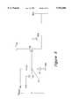
- FIG. 1shows a prior art active pixel sensor structure which requires four transistors Q1, Q2, Q3, Q4, a floating diode FD and a MOS capacitor CM1. Due to the large number of circuit elements, this active pixel structure requires a significant amount of integrated circuit area.
- the RST line of this structureallows the floating diode FD to be discharged.
- a PG connectionincludes a polysilicon wire. By adjusting the voltage potential of the PG connection, the MOS capacitor CM1 is created due to depletion of a channel region created under the PG connection.
- a TX connectionis driven to a fixed voltage potential to provide a potential barrier for the MOS capacitor CM1.
- the depletion region which creates the MOS capacitor CM1is generated by biasing the PG connection to a high voltage potential (Vdd).
- the MOS capacitor CM1will accumulate electrons when exposed to light which excites the electrons. After a period of integration, the electrons accumulated on the MOS capacitor are transferred to the floating diode FD because the MOS capacitor CM1 ceases to exist.
- a signal voltageis stored across the floating diode FD which is proportional to the intensity of light received by the active pixel sensor.
- the SEL connectionallows the signal voltage across the floating diode to be sampled. As was previously mentioned, the substantial number of electrical components associated with this active pixel sensor require a large amount of integrated circuit area which limits the fill factor of the sensor.
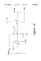
- FIG. 2shows a prior art active pixel sensor structure which requires three transistors Q5, Q6, Q7 and a photo-diode PD1.
- the photo-diode PD1collects charge at a rate which is proportional to the intensity of light received by the photo-diode PD1.
- Capacitance coupled to the node FDaccumulates charge as the photo-diode PD1 collects electrons.
- the active pixel sensor structure shown in FIG. 2includes fewer transistors than the active pixel sensor structure shown in FIG. 1. Therefore, the active pixel sensor structure shown in FIG. 2 is smaller than the active pixel sensor structure shown in FIG. 1.
- miniaturization of an array of these pixel sensorsis limited by the fill factor of the pixel sensors. To improve the fill factor, the number of transistors in each pixel sensor must be further reduced.
- FIG. 3shows a prior art single NPN bipolar transistor active pixel sensor.
- the single transistoris an NPN bipolar transistor which requires an N-well when the active pixel sensor is implemented using a P-doped substrate.
- a N-wellsare large when implemented using a CMOS fabrication process.
- a base node of the NPN bipolar transistoris essentially floating. Therefore, resetting the active pixel sensor at the base node is not very easy. As a result, this active pixel sensor can suffer image lagging.
- FIG. 4shows a prior art passive pixel sensor structure which requires two transistors Q9, Q10 and a photo-diode PD2.
- the photo-diode PD2includes a junction capacitance CD.
- An output of the passive pixelis connected to a bitline which includes a bus capacitance CBUS.
- the transistor Q10is turned on when selecting the active pixel sensor.
- the capacitance of the junction capacitance CDis effectively connected in parallel with a capacitance of a bus CBUS.
- the fill factor of this pixel sensoris high.
- the signal to noise ratiois not scalable with an increase in the number of pixel sensors within an array of the pixel sensors.
- a voltage potential created by charge stored on the capacitance of the photo-diodeis shared with the capacitance of bus.
- the voltage charge collected on the capacitance of the photo-diodeis greatly reduced as the charge on the capacitance of the photo-diode is shared with the capacitance of bus.
- the capacitance of the busincreases as the size of the active pixel sensor array increases. Therefore, the signal to noise ratio of a signal generated by the active pixel sensor is greatly reduced when the active pixel sensor is within a large array of active pixel sensors.
- the active pixel sensorIt is desirable to have an active pixel sensor which is physically small and provides a high fill factor.
- the active pixel sensorwould provide low-noise read-out signals, electronic shuttering and anti-blooming. Further, the active pixel sensor could be integrated with image processing circuitry and fabricated using a low-cost CMOS process.
- the present inventionprovides an active pixel sensor which is compatible with low-cost CMOS fabrication processes.
- the active pixel sensoris physically small and provides a high-fill factor.
- the active pixel sensorprovides low-noise read-out signals, anti-blooming and electronic shuttering. Further, the active pixel sensor can be integrated with analog and digital processing circuitry.
- a first embodiment of this inventionincludes an active pixel sensor.
- the active pixel sensorincludes an amplify/compare transistor which has a threshold voltage.
- the amplify/compare transistorcouples an input of the amplify/compare transistor to an output of the amplify/compare transistor when the input of the amplify/compare transistor exceeds the threshold voltage.
- a photo-diodegenerates a signal voltage which has a voltage level dependent upon the intensity of light received by the photo-diode. The signal voltage is coupled to the input of the amplify/compare transistor.
- a reset transistorcouples a reset line to the photo-diode and discharges the photo-diode when the reset line is active.
- a coupling capacitorcouples a select line to the input of the amplify/compare transistor.
- the select linecauses the input to the amplify/compare transistor to exceed the threshold voltage and thereby couple the signal voltage to the output of the amplify/compare transistor.
- the threshold voltageis adjusted to enhance the dynamic range of the signal voltage coupled to the output of the amplify/compare transistor.
- a back gate of the amplify/compare transistoris connected to a P-type substrate which is connected to a circuit ground.
- Another embodiment of the inventionis similar to the first embodiment, but includes the amplify/compare transistor being an N-type MOSFET and the reset transistor being an N-type MOSFET. Further, the back gate of the amplify/compare transistor is connected to a P-well which is connected to a presettable voltage.
- Another embodiment of the inventionis similar to the first embodiment, but includes the amplify/compare transistor being an P-type MOSFET and the reset transistor being an N-type MOSFET. Further, a back gate of the amplify/compare transistor is connected to a variable voltage which adjusts the threshold voltage.
- Another embodiment of the inventionis similar to the first embodiment, but includes the amplify/compare transistor being an P-type MOSFET and the reset transistor being an P-type MOSFET. Further, a back gate of the amplify/compare transistor is connected to a variable voltage which adjusts the threshold voltage.
- FIG. 1shows a prior art active pixel sensor structure which includes four transistors.
- FIG. 2shows a prior art active pixel sensor structure which includes three transistors.
- FIG. 3shows a prior art active pixel sensor structure which includes a single NPN bipolar transistor.
- FIG. 4shows a prior art passive pixel sensor structure which includes two transistors.
- FIG. 5is a circuit schematic of a first embodiment of the invention.
- FIG. 6shows an implementation of the embodiment shown in FIG. 5.
- FIG. 7is a timing diagram of the signals shown in the schematic of FIG. 5 when detecting the intensity of light being received by the active pixel sensor of the invention.
- FIG. 8is a circuit schematic of a second embodiment of the invention.
- FIG. 9shows an implementation of the embodiment shown in FIG. 8.
- FIG. 10is a circuit schematic of a third embodiment of the invention.
- FIG. 11shows an implementation of the embodiment shown in FIG. 10.
- FIG. 12is a circuit schematic of a fourth embodiment of the invention.
- FIG. 13shows an implementation of the embodiment shown in FIG. 12.
- FIG. 14is a timing diagram of the signals shown in the schematic of FIG. 12 when detecting the intensity of light being received by the active pixel sensor of the invention.
- FIG. 15is a circuit schematic of a fifth embodiment of the invention.
- the inventionis embodied in a salient integration mode active pixel sensor.
- the active pixel sensorprovides a small pixel size and a high-fill factor.
- the active pixel sensorprovides low-noise read-out signals, anti-blooming and electronic shuttering. Further, the active pixel sensor can be integrated with analog and digital processing circuitry using a low-cost fabrication process.
- FIG. 5is a circuit schematic of a first embodiment of the invention.
- This embodimentis an active pixel sensor which includes an N-type MOSFET reset transistor M1, an N-type MOSFET amplify/compare transistor M2, a coupling capacitor C1 and a photo-diode D1.
- the amplify/compare transistor M2includes a channel implant which includes a high substrate impurity concentration. The channel implant results in the amplify/compare transistor M2 having a threshold voltage which is higher than a typical N-type MOSFET transistor.
- the input (gate) of the amplify/compare transistor M2is connected to the cathode of the photo-diode D1.
- the connection nodeis designated as signal a node N1 in FIG. 5.
- the circuit schematic of FIG. 5includes several controlled inputs and a single output.
- the controlled inputsinclude Vdd, Vreset, GND, SEL and RST.
- Vddis a power supply which generally also powers digital and analog signal processing circuitry associated with the active pixel sensor.
- GNDis a circuit ground.
- Vresetis a reference voltage which determines the bias of the signal node N1 across the photo-diode D1 when the active pixel sensor is reset. Vreset can also be connected to the power supply voltage Vdd. However, this results in the active pixel sensor requiring a longer amount of time to reset.
- the SEL inputis active when selecting the active pixel sensor for the purpose of sensing the intensity of light being received by the active pixel sensor.
- the SEL inputis a pulsed input which biases the circuit elements of the active pixel sensor for the purpose of coupling a voltage potential across the photo-diode D1 to an output BUS.
- the RST inputresets the active pixel sensor by biasing the signal node N1 and discharging the photo-diode D1.
- the pulsed SEL input and the coupling capacitor C1can be physically realized by fabricating a polysilicon layer over an N-island diffusion layer. Fabrication of a polysilicon layer over an N-island diffusion layer is well known in the art of semiconductor fabrication.
- FIG. 6shows an implementation of the embodiment shown in FIG. 5.
- This embodimentincludes a P-doped substrate 20.
- the P-doped substrate 20includes several N-doped diffusion regions 22, 24, 26, 28.
- the embodimentfurther includes gate oxide regions 29, 30, 31, a poly-silicon layer 33, a metal layer 32, a photo-resist metal layer 35 and a field oxide region 34.
- the reset transistor M1is formed by the N-doped diffusion region 22, the gate oxide region 29, the P-doped substrate 20 and the N-doped diffusion region 24.
- the amplify/compare transistor M2is formed by the N-doped diffusion region 26, the gate oxide region 31, the P-doped substrate 20 and the N-doped diffusion region 28.
- the amplify/compare transistor M2further includes a channel implant 37.
- the photo-diode D1is formed by the P-doped substrate 20 and the N-doped diffusion region 24.
- the coupling capacitoris formed by the gate oxide region 30 and the poly-silicon layer 33.
- FIG. 7is a timing diagram of the signals shown in the schematic of FIG. 5 when detecting the intensity of light received by the active pixel sensor of the invention. Detecting the intensity of the light can be sectioned into four major events or steps.
- a first event 71includes the reset line (RST) of the active pixel sensor pulsing from a low reset voltage 81 to a high reset voltage 83.
- the reset line (RST)When the reset line (RST) is at the high reset voltage, the reset transistor M1 turns on and conducts current. When the reset transistor M1 conducts current, the signal node N1 is pulled up to the voltage potential of the Vreset input.
- the voltage potential of the Vreset inputis adjustable. However, generally Vreset should be set to a voltage potential of less than the high reset voltage 83 minus the threshold voltage of the reset transistor M1 to reduce the settling time and noise. For example, if the high reset voltage 83 is 5 volts and the threshold of the reset transistor M1 is 0.7 volts, then the voltage potential of the Vreset voltage should be less than 4.3 volts.
- a second event 73includes the voltage potential of the SEL input pulsing from a high select voltage 85 to a low select voltage 87.
- the RST inputis at the low reset voltage 81 for the duration of time the SEL input remains at the low select voltage 87.
- the SEL inputis coupled to the signal node N1 through the coupling capacitor C1.
- the rapid change in voltage across the coupling capacitor C1pulls charge away from the coupling capacitor C1.
- the voltage potential of the signal node N1changes by the difference between the high select voltage 85 and the low select voltage 87, multiplied by (C1/(C1+Cjunction)), where Cjunction is ajunction capacitance of the photo-diode D1.
- the voltage potential of the signal node N1continues to decrease after the second event 73 as electrons accumulate on the capacitance of the signal node N1 due to the photo-diode receiving light.
- the voltage potential of the signal node N1will continue to decrease until one of two possible events occur. Either the voltage potential of the SEL input pulses back up to the high select voltage 85, or the voltage potential of the signal node N1 will decrease to the point that the reset transistor M1 begins to conduct.
- Ramps 91, 93, 95show several different ramps rates of the voltage potential of the signal node N1. The rate that the voltage potential of the signal node N1 decreases is proportional to the intensity of light received by the photo-diode. The greater the intensity of the light, the faster electrons are collected on the capacitance of the signal node N1 and the faster the voltage potential on the signal node N1 decreases. For example, ramp 91 depicts a faster ramp rate than ramp 95. Therefore, the intensity of light received by photo-diode D1 in generating the ramp 91 is greater than the intensity of light received by the photo-diode D1 in generating the ramp 95.
- the voltage potential of the signal node N1will increase by the same amount that the voltage potential of the signal node N1 decreased when the SEL input pulsed to the low select voltage. More precisely, the voltage potential of the signal node N1 increases by the difference between the high select voltage and the low select voltage, multiplied by (C1/(C1+Cjunction)).
- the pulse width of the SEL inputis determined by knowing the intensity the light to be received by the photo-diode D1. Generally, it is desirable to avoid the condition that results when the reset transistor M1 conducts due to the charge conducted by the photo-diode. However, a feature of the invention includes prevention against the occurrence of blooming when this condition occurs. If the reset transistor M1 did not conduct, the voltage potential of the signal node N1 would continue to decrease until the performance of neighboring active pixel sensor would be affected. The reset transistor M1 prevents the active pixel sensor from suffering from blooming.
- the factorsinclude the threshold voltage of the amplify/compare transistor M2, and the voltage potential of the low reset voltage 81. Increasing the threshold of the amplify/compare transistor M2 will increase the amount the voltage potential of the signal node N1 can vary. Decreasing the voltage potential of the low reset voltage 81 will increase the amount the voltage potential of the signal node N1 can vary.
- a third event 75includes the voltage potential of the SEL input transitioning from the low select voltage to 87 the high select voltage 85.
- the voltage potential of the signal node N1will increase by the difference between the high select voltage 85 and the low select voltage 87, multiplied by (C1/(C1+Cjunction)).
- Typical values of the voltage potential of the signal node N1are depicted as levels 97, 99. This increase in the voltage potential of the signal node N1 will cause the voltage potential at the input of the amplify/compare transistor M2 to be greater than the threshold voltage of the amplify/compare transistor M2. Therefore, the amplify/compare transistor M2 will begin to conduct.
- the voltage potential on the signal node N1is coupled through the amplify/compare transistor M2 to the BUS output.
- the BUS outputis sampled.
- the sampled outputis a representation of the intensity of the light received by the photo-diode D1.
- the BUS outputcan be sampled by an analog to digital converter (ADC) circuit.
- ADCanalog to digital converter
- ADC circuitswhich are well known may be used. The sampling, however, must occur after the third event 75 and before a fourth event 77 in which the RST of the active pixel sensor transitions from the low reset voltage 81 to the high reset voltage 83.
- the term salient integration modeindicates that integration of charge collected by the photo-diode D1 occurs while the signal node N1 is below the threshold voltage of the amplify/compare transistor M2. That is, the integration of the collected charge occurs while the amplify/compare transistor M2 is not conducting.
- FIG. 8is a circuit schematic depicting a second embodiment of the invention. This schematic is very similar to the circuit schematic shown in FIG. 5. However, the N-type MOSFET amplify/compare transistor M2 is replaced with an N-type MOSFET amplify/compare transistor M3 which includes a back gate connected to a P-well. The N-type MOSFET reset transistor M1 is replaced with an N-type MOSFET reset transistor M4 which includes a back gate connected to the P-well. The P-well is connected to an adjustable voltage. Unlike the first embodiment of the invention shown in FIG. 5, the threshold voltage of this embodiment is adjustable. An array of active pixel sensor each according to this embodiment provides for selective adjustment of the threshold voltage of each active pixel sensor individually. The P-well, however, requires a greater amount of integrated circuit substrate area. Therefore, the fill factor for this embodiment is not as great as the first embodiment.
- FIG. 9shows an implementation of the embodiment shown in FIG. 8.
- This embodimentincludes an N-doped substrate 21 and a P-well 23.
- the reset transistor M4is formed by the N-doped diffusion region 22, the gate oxide region 29, the P-well 23 and the N-doped diffusion region 24.
- the amplify/compare transistor M3is formed by the N-doped diffusion region 26, the gate region 31, the P-well 23, and the N-doped diffusion region 28.
- the photo-diode D1is formed by the P-well 23 and the N-doped diffusion region 24.
- the coupling capacitoris formed by the gate oxide region 30 and the polysilicon layer 33.
- FIG. 10is a circuit schematic depicting a third embodiment of the invention. This schematic is very similar to the circuit schematic shown in FIG. 5, but the N-type MOSFET amplify/compare transistor M2 is replaced with a P-type MOSFET amplify/compare transistor M5, and the N-type MOSFET reset transistor M1 is replaced with a P-type MOSFET reset transistor M6. A back gate of the amplify/compare transistor M5 is connected to an N-well. The N-well is connected to an adjustable voltage.
- FIG. 11shows an implementation of the embodiment shown in FIG. 10.
- This embodimentincludes an N-well 41 and P-doped diffusion regions 43, 45.
- the reset transistor M6is formed by the N-doped diffusion region 22, the gate oxide region 29, the P-doped substrate 20 and the N-doped diffusion region 24.
- the amplify/compare transistor M5is formed by the P-doped diffusion region 43, the gate region 31, the N-well 41, and the P-doped diffusion region 45.
- the photo-diode D1is formed by the P-doped substrate 20 and the N-doped diffusion region 24.
- the coupling capacitoris formed by the gate oxide region 30 and the polysilicon layer 33.
- FIG. 12is a circuit schematic depicting a fourth embodiment of the invention.
- This embodimentincludes a P-type MOSFET amplify/compare transistor M7 and a P-type MOSFET reset transistor M8.
- a back gate of the amplify/compare transistor M7is connected to an N-well which is connected to an adjustable voltage.
- a back gate of the reset transistor M8is connected to an N-well which is connected to an adjustable voltage.
- FIG. 13shows an implementation of the embodiment shown in FIG. 12.
- This embodimentincludes an P-doped substrate 25, an N-well 27 and P-doped diffusion regions 46, 48.
- the reset transistor M8is formed by the P-doped diffusion region 42, the gate oxide region 29, the N-well 27 and the P-doped diffusion region 44.
- the amplify/compare transistor M7is formed by the P-doped diffusion region 46, the gate region 31, the N-well 27, and the P-doped diffusion region 48.
- the photo-diode D1is formed by the N-well 27 and the P-doped diffusion region 44.
- the coupling capacitoris formed by the gate oxide region 30 and the polysilicon layer 33.
- FIG. 14is a timing diagram of the signals shown in the schematic of FIG. 12 when detecting the intensity of light received by the active pixel sensor of the invention. Detecting the intensity of the light can be sectioned into four major events or steps.
- a first event 201includes the reset line (RST) of the active pixel sensor pulsing from a high reset voltage 103 to a low reset voltage 101.
- the reset line (RST)When the reset line (RST) is at the low reset voltage 101, the reset transistor M8 turns on and conducts current. When the reset transistor M8 conducts current, the signal node N1 is pulled down to the voltage potential of the Vreset input.
- the voltage potential of the Vreset inputis adjustable. However, generally Vreset should be set to a voltage potential of greater than the low reset voltage 101 plus the threshold voltage of the reset transistor M8 to reduce the settling time. For example, if the low reset voltage 101 is 0 volts and the threshold of the reset transistor M8 is 0.7 volts, then the voltage potential of the Vreset voltage should be less than 0.7 volts.
- a second event 203includes the voltage potential of the SEL input pulsing from a low select voltage 105 to a high select voltage 107.
- the RST inputis at the high reset voltage 103 for the duration of time the SEL input remains at the high select voltage 107.
- the SEL inputis coupled to the signal node N1 through the coupling capacitor C1.
- the rapid change in voltage across the coupling capacitor C1causes charge to collect on the coupling capacitor C1.
- the voltage potential of the signal node N1changes by difference between the low select voltage 105 and the high select voltage 107, multiplied by (C1/(C1+Cjunction)), where Cjunction is ajunction capacitance of the photo-diode D1.
- the voltage potential of the signal node N1continues to increase after the second event 93 as charge is pulled away from the capacitance of the signal node N1 due to the photo-diode receiving light.
- the voltage potential of the signal node N1will continue to increase until one of two possible events occur. Either the voltage potential of the SEL input pulses back down to the low select voltage 105, or the voltage potential of the signal node N1 will increase to the point that the reset transistor M8 begins to conduct.
- Ramps 111, 113, 115show several different ramps rates of the voltage potential of the signal node N1. The rate that the voltage potential of the signal node N1 increases is proportional to the intensity of light received by the photo-diode. The greater the intensity of the light, the faster electrons are pulled away from the capacitance of the signal node N1 and the faster the voltage potential on the signal node N1 increases. For example, ramp 111 depicts a faster ramp rate than ramp 115. Therefore, the intensity of light received by photo-diode D1 in generating the ramp 111 is greater than the intensity of light received by the photo-diode D1 in generating the ramp 115.
- the voltage potential of the signal node N1will decrease by the same amount that the voltage potential of the signal node increased when the SEL input pulsed to the high select voltage 107. More precisely, the voltage potential of the signal node N1 decreases by the difference between the low select voltage 105 and the high select voltage 107, multiplied by (C1/(C1+Cjunction)).
- the pulse width of the SEL inputis determined by knowing the intensity the light to be received by the photo-diode D1. Generally, it is desirable to avoid the condition that results when the reset transistor M8 conducts due to the charge conducted by the photo-diode. However, a feature of the invention includes prevention against the occurrence of blooming when this condition occurs. If the reset transistor M8 did not conduct, the voltage potential of the signal node N1 would continue to decrease until the performance of neighboring active pixel sensor would be affected. The reset transistor M8 prevents the active pixel sensor from suffering from blooming.
- the factorsinclude the threshold voltage of the amplify/compare transistor M7, and the voltage potential of the low reset voltage 101. Increasing the threshold of the amplify/compare transistor M7 will increase the amount the voltage potential of the signal node N1 can vary. Decreasing the voltage potential of the low reset voltage 101 increase the amount the voltage potential of the signal node N1 can vary.
- a third event 205includes the voltage potential of the SEL input transitioning from the high select voltage 107 he low select voltage 105.
- the voltage potential of the signal node N1will decrease by the difference between the low select voltage 105 and the high select voltage 107, multiplied by (C1/(C1+Cjunction)).
- Typical values of the voltage potential of the signal node N1are depicted as levels 117, 119. This decrease in the voltage potential of the signal node N1 will cause the voltage potential at the input of the amplify/compare transistor M7 to be greater than the threshold voltage of the amplify/compare transistor M7. Therefore, the amplify/compare transistor M7 will begin to conduct.
- the voltage potential on the signal node N1is coupled through the amplify/compare transistor M7 to the BUS output.
- the BUS outputis sampled.
- the sampled outputis a representation of the intensity of the light received by the photo-diode D1.
- the BUS outputcan be sampled by an analog to digital converter (ADC) circuit.
- ADCanalog to digital converter
- ADC circuitswhich are well known may be used. The sampling, however, must occur after the third event 205 and before a fourth event 207 in which the RST of the active pixel sensor transitions from the low reset voltage 101 to the high reset voltage 103.
- FIG. 15is a circuit schematic depicting a fifth embodiment of the invention which only requires a single transistor.
- This embodimentincludes a reset diode D2, an N-type MOSFET amplify/compare transistor M9, a coupling capacitor C1 and a photo-diode D1.
- the amplify/compare transistor M9includes a channel implant which includes a high substrate impurity concentration which allows for adjustment of the threshold voltage of the amplify/compare transistor M9.
- the channel implantresults in the amplify/compare transistor M9 having a threshold voltage which is higher than a typical N-type MOSFET transistor.
- the input (gate) of the amplify/compare transistor M9is connected to the cathode of the photo-diode D1. This connection node is designated as a signal node N1 in FIG. 15.
- the RST inputresets the active pixel sensor by forward biasing the reset diode D2 and charging or discharging the photo-diode D1.
- the RST inputis biased at a higher voltage potential, such as Vdd, to reset the active pixel sensor.
- the RST inputis biased at a lower voltage potential during the period of time in which electrons are collected on the capacitance of the signal node due to the photo-diode D1 receiving light.
Landscapes
- Engineering & Computer Science (AREA)
- Multimedia (AREA)
- Signal Processing (AREA)
- Power Engineering (AREA)
- Physics & Mathematics (AREA)
- General Physics & Mathematics (AREA)
- Spectroscopy & Molecular Physics (AREA)
- Solid State Image Pick-Up Elements (AREA)
- Transforming Light Signals Into Electric Signals (AREA)
Abstract
Description
Claims (17)
Priority Applications (4)
| Application Number | Priority Date | Filing Date | Title |
|---|---|---|---|
| US08/984,457US5952686A (en) | 1997-12-03 | 1997-12-03 | Salient integration mode active pixel sensor |
| DE19832791ADE19832791B4 (en) | 1997-12-03 | 1998-07-21 | Active pixel sensor with a pronounced integration mode |
| GB9825855AGB2332049B (en) | 1997-12-03 | 1998-11-25 | Pixel sensor |
| JP35847198AJP4344871B2 (en) | 1997-12-03 | 1998-12-02 | Active pixel sensor with remarkable integration mode |
Applications Claiming Priority (1)
| Application Number | Priority Date | Filing Date | Title |
|---|---|---|---|
| US08/984,457US5952686A (en) | 1997-12-03 | 1997-12-03 | Salient integration mode active pixel sensor |
Publications (1)
| Publication Number | Publication Date |
|---|---|
| US5952686Atrue US5952686A (en) | 1999-09-14 |
Family
ID=25530571
Family Applications (1)
| Application Number | Title | Priority Date | Filing Date |
|---|---|---|---|
| US08/984,457Expired - LifetimeUS5952686A (en) | 1997-12-03 | 1997-12-03 | Salient integration mode active pixel sensor |
Country Status (4)
| Country | Link |
|---|---|
| US (1) | US5952686A (en) |
| JP (1) | JP4344871B2 (en) |
| DE (1) | DE19832791B4 (en) |
| GB (1) | GB2332049B (en) |
Cited By (33)
| Publication number | Priority date | Publication date | Assignee | Title |
|---|---|---|---|---|
| US6111245A (en)* | 1998-04-22 | 2000-08-29 | National Science Council Of Republic Of China | Low voltage reverse bias arrangement for an active pixel sensor |
| WO2001024269A1 (en)* | 1999-09-30 | 2001-04-05 | Infineon Technologies Ag | Arrangement with image sensors |
| US6242728B1 (en)* | 1998-08-20 | 2001-06-05 | Foveon, Inc. | CMOS active pixel sensor using native transistors |
| US6259124B1 (en)* | 1998-08-07 | 2001-07-10 | Eastman Kodak Company | Active pixel sensor with high fill factor blooming protection |
| US20010011736A1 (en)* | 1999-12-14 | 2001-08-09 | Bart Dierickx | Pixel structure with improved charge transfer |
| US20020018132A1 (en)* | 2000-06-06 | 2002-02-14 | Takashi Watanabe | Solid-state image sensor device and solid-state image sensor apparatus including same |
| US6501109B1 (en) | 2001-08-29 | 2002-12-31 | Taiwan Semiconductor Manufacturing Company | Active CMOS pixel with exponential output based on the GIDL mechanism |
| US20030230771A1 (en)* | 2002-06-17 | 2003-12-18 | Seok-Ha Lee | Image sensors including photodetector and bypass device connected to a power supply voltage, and methods of fabricating same |
| US20040014254A1 (en)* | 1998-09-18 | 2004-01-22 | Capella Microsystems,Inc. | Photodetector and device employing the photodetector for converting an optical signal into an electrical signal |
| US6697111B1 (en)* | 1998-04-08 | 2004-02-24 | Ess Technology, Inc. | Compact low-noise active pixel sensor with progressive row reset |
| US6710804B1 (en) | 2000-01-18 | 2004-03-23 | Eastman Kodak Company | CMOS active pixel image sensor with extended dynamic range and sensitivity |
| US6727946B1 (en)* | 1999-12-14 | 2004-04-27 | Omnivision Technologies, Inc. | APS soft reset circuit for reducing image lag |
| US20040135207A1 (en)* | 2003-01-09 | 2004-07-15 | Taner Dosluoglu | CMOS pixel with dual gate PMOS |
| US6815791B1 (en)* | 1997-02-10 | 2004-11-09 | Fillfactory | Buried, fully depletable, high fill factor photodiodes |
| US6882367B1 (en)* | 2000-02-29 | 2005-04-19 | Foveon, Inc. | High-sensitivity storage pixel sensor having auto-exposure detection |
| US6888572B1 (en)* | 2000-10-26 | 2005-05-03 | Rockwell Science Center, Llc | Compact active pixel with low-noise image formation |
| EP1152472A3 (en)* | 2000-04-28 | 2005-06-08 | Eastman Kodak Company | Image sensor pixel for global electronic shuttering |
| US20050195305A1 (en)* | 2004-03-05 | 2005-09-08 | Jeong-Ho Lyu | Biasing circuits, solid state imaging devices, and methods of manufacturing the same |
| US20060044438A1 (en)* | 2004-08-25 | 2006-03-02 | Mauritzson Richard A | Pixel for boosting pixel reset voltage |
| US7015448B2 (en)* | 2002-08-22 | 2006-03-21 | Micron Technology, Inc. | Dark current reduction circuitry for CMOS active pixel sensors |
| US20070145447A1 (en)* | 2005-12-28 | 2007-06-28 | Samsung Electronics Co. Ltd. | Pixel and CMOS image sensor including the same |
| DE10063094B4 (en)* | 2000-03-02 | 2008-04-24 | Magnachip Semiconductor, Ltd. | Active pixel circuit in a CMOS image sensor |
| US20080315263A1 (en)* | 2007-06-20 | 2008-12-25 | Micron Technology, Inc. | Imager pixel structure and circuit |
| US7653272B2 (en) | 2002-09-19 | 2010-01-26 | Avago Technologies Fiber Ip (Singapore) Pte. Ltd. | Highly parallel optical communication system with intracard and intercard communications |
| US7750958B1 (en) | 2005-03-28 | 2010-07-06 | Cypress Semiconductor Corporation | Pixel structure |
| US20100176275A1 (en)* | 2009-01-15 | 2010-07-15 | Raytheon Company | Multipurpose Photodetector Amplifier and Control Methods |
| US7808022B1 (en) | 2005-03-28 | 2010-10-05 | Cypress Semiconductor Corporation | Cross talk reduction |
| CN102544038A (en)* | 2010-12-13 | 2012-07-04 | 全视科技有限公司 | Method for generating photodetector isolation in image sensors |
| CN103094294A (en)* | 2009-12-03 | 2013-05-08 | 索尼公司 | Imaging element and camera system |
| US8476567B2 (en) | 2008-09-22 | 2013-07-02 | Semiconductor Components Industries, Llc | Active pixel with precharging circuit |
| TWI449168B (en)* | 2009-02-05 | 2014-08-11 | Sony Corp | Solid-state imaging device, method of manufacturing solid-state imaging device, method of driving solid-state imaging device, and electronic device |
| CN108519151A (en)* | 2018-03-23 | 2018-09-11 | 京东方科技集团股份有限公司 | Light detection circuit, light detection method and light detection device |
| WO2022047925A1 (en)* | 2020-09-03 | 2022-03-10 | 深圳市华星光电半导体显示技术有限公司 | Drive circuit and drive method therefor |
Families Citing this family (11)
| Publication number | Priority date | Publication date | Assignee | Title |
|---|---|---|---|---|
| KR100507879B1 (en)* | 2000-08-31 | 2005-08-17 | 매그나칩 반도체 유한회사 | Unit pixel of cmos image sensor |
| GB2374926A (en)* | 2001-04-28 | 2002-10-30 | Secr Defence | Log-linear pixel circuit and pixel array system. |
| JP2003023144A (en)* | 2001-07-06 | 2003-01-24 | Semiconductor Energy Lab Co Ltd | Semiconductor device |
| US7443427B2 (en)* | 2002-08-23 | 2008-10-28 | Micron Technology, Inc. | Wide dynamic range linear-and-log active pixel |
| JP2006343229A (en)* | 2005-06-09 | 2006-12-21 | Mitsubishi Electric Corp | Image sensor |
| US7875916B2 (en) | 2005-09-28 | 2011-01-25 | Eastman Kodak Company | Photodetector and n-layer structure for improved collection efficiency |
| US7728277B2 (en) | 2005-11-16 | 2010-06-01 | Eastman Kodak Company | PMOS pixel structure with low cross talk for active pixel image sensors |
| GB2439098A (en)* | 2006-06-12 | 2007-12-19 | Sharp Kk | Image sensor and display |
| GB2439118A (en) | 2006-06-12 | 2007-12-19 | Sharp Kk | Image sensor and display |
| JP4946486B2 (en)* | 2006-10-02 | 2012-06-06 | セイコーエプソン株式会社 | Detection device driving method, detection device, electro-optical device, and electronic apparatus |
| JP4882825B2 (en)* | 2007-03-28 | 2012-02-22 | セイコーエプソン株式会社 | DETECTING DEVICE, ITS DRIVE METHOD, AND ELECTRONIC DEVICE |
Citations (4)
| Publication number | Priority date | Publication date | Assignee | Title |
|---|---|---|---|---|
| US5307169A (en)* | 1991-05-07 | 1994-04-26 | Olympus Optical Co., Ltd. | Solid-state imaging device using high relative dielectric constant material as insulating film |
| US5408113A (en)* | 1992-06-30 | 1995-04-18 | Ricoh Company, Ltd. | High sensitivity improved photoelectric imaging device with a high signal to noise ratio |
| US5587596A (en)* | 1995-09-20 | 1996-12-24 | National Semiconductor Corporation | Single MOS transistor active pixel sensor cell with automatic anti-blooming and wide dynamic range |
| US5608243A (en)* | 1995-10-19 | 1997-03-04 | National Semiconductor Corporation | Single split-gate MOS transistor active pixel sensor cell with automatic anti-blooming and wide dynamic range |
Family Cites Families (4)
| Publication number | Priority date | Publication date | Assignee | Title |
|---|---|---|---|---|
| US4023048A (en)* | 1975-12-15 | 1977-05-10 | International Business Machines Corporation | Self-scanning photo-sensitive circuits |
| JPH0812906B2 (en)* | 1986-07-11 | 1996-02-07 | キヤノン株式会社 | Method for manufacturing photoelectric conversion device |
| JP2765635B2 (en)* | 1991-01-11 | 1998-06-18 | キヤノン株式会社 | Photoelectric conversion device |
| JPH07115184A (en)* | 1993-08-24 | 1995-05-02 | Canon Inc | Stacked solid-state imaging device and manufacturing method thereof |
- 1997
- 1997-12-03USUS08/984,457patent/US5952686A/ennot_activeExpired - Lifetime
- 1998
- 1998-07-21DEDE19832791Apatent/DE19832791B4/ennot_activeExpired - Lifetime
- 1998-11-25GBGB9825855Apatent/GB2332049B/ennot_activeExpired - Lifetime
- 1998-12-02JPJP35847198Apatent/JP4344871B2/ennot_activeExpired - Lifetime
Patent Citations (4)
| Publication number | Priority date | Publication date | Assignee | Title |
|---|---|---|---|---|
| US5307169A (en)* | 1991-05-07 | 1994-04-26 | Olympus Optical Co., Ltd. | Solid-state imaging device using high relative dielectric constant material as insulating film |
| US5408113A (en)* | 1992-06-30 | 1995-04-18 | Ricoh Company, Ltd. | High sensitivity improved photoelectric imaging device with a high signal to noise ratio |
| US5587596A (en)* | 1995-09-20 | 1996-12-24 | National Semiconductor Corporation | Single MOS transistor active pixel sensor cell with automatic anti-blooming and wide dynamic range |
| US5608243A (en)* | 1995-10-19 | 1997-03-04 | National Semiconductor Corporation | Single split-gate MOS transistor active pixel sensor cell with automatic anti-blooming and wide dynamic range |
Cited By (65)
| Publication number | Priority date | Publication date | Assignee | Title |
|---|---|---|---|---|
| US20070145503A1 (en)* | 1997-02-10 | 2007-06-28 | Bart Dierickx | Pixel structure with improved charge transfer |
| US6815791B1 (en)* | 1997-02-10 | 2004-11-09 | Fillfactory | Buried, fully depletable, high fill factor photodiodes |
| US7253019B2 (en) | 1997-02-10 | 2007-08-07 | Cypress Semiconductor Corporation (Belgium) Bvba | Buried, fully depletable, high fill factor photodiodes |
| US20050064617A1 (en)* | 1997-02-10 | 2005-03-24 | Bart Dierickx | Buried, fully depletable, high fill factor photodiodes |
| US6697111B1 (en)* | 1998-04-08 | 2004-02-24 | Ess Technology, Inc. | Compact low-noise active pixel sensor with progressive row reset |
| US6111245A (en)* | 1998-04-22 | 2000-08-29 | National Science Council Of Republic Of China | Low voltage reverse bias arrangement for an active pixel sensor |
| US6259124B1 (en)* | 1998-08-07 | 2001-07-10 | Eastman Kodak Company | Active pixel sensor with high fill factor blooming protection |
| US6476372B2 (en) | 1998-08-20 | 2002-11-05 | Foveon, Inc. | CMOS active pixel sensor using native transistors |
| US6242728B1 (en)* | 1998-08-20 | 2001-06-05 | Foveon, Inc. | CMOS active pixel sensor using native transistors |
| US20040014254A1 (en)* | 1998-09-18 | 2004-01-22 | Capella Microsystems,Inc. | Photodetector and device employing the photodetector for converting an optical signal into an electrical signal |
| US6887735B2 (en)* | 1998-09-18 | 2005-05-03 | Capella Microsystems, Inc. | Photodetector and device employing the photodetector for converting an optical signal into an electrical signal |
| US7030434B1 (en) | 1999-09-30 | 2006-04-18 | Infineon Technologies Ag | Arrangement with image sensors |
| WO2001024269A1 (en)* | 1999-09-30 | 2001-04-05 | Infineon Technologies Ag | Arrangement with image sensors |
| US20010011736A1 (en)* | 1999-12-14 | 2001-08-09 | Bart Dierickx | Pixel structure with improved charge transfer |
| US20040080646A1 (en)* | 1999-12-14 | 2004-04-29 | Tiemin Zhao | APS soft reset circuit for reducing image lag |
| US6727946B1 (en)* | 1999-12-14 | 2004-04-27 | Omnivision Technologies, Inc. | APS soft reset circuit for reducing image lag |
| US7199410B2 (en) | 1999-12-14 | 2007-04-03 | Cypress Semiconductor Corporation (Belgium) Bvba | Pixel structure with improved charge transfer |
| US7456887B2 (en) | 1999-12-14 | 2008-11-25 | Omnivision Technologies, Inc. | APS soft reset circuit for reducing image lag |
| US6710804B1 (en) | 2000-01-18 | 2004-03-23 | Eastman Kodak Company | CMOS active pixel image sensor with extended dynamic range and sensitivity |
| US6882367B1 (en)* | 2000-02-29 | 2005-04-19 | Foveon, Inc. | High-sensitivity storage pixel sensor having auto-exposure detection |
| DE10063094B4 (en)* | 2000-03-02 | 2008-04-24 | Magnachip Semiconductor, Ltd. | Active pixel circuit in a CMOS image sensor |
| EP1152472A3 (en)* | 2000-04-28 | 2005-06-08 | Eastman Kodak Company | Image sensor pixel for global electronic shuttering |
| US7129979B1 (en) | 2000-04-28 | 2006-10-31 | Eastman Kodak Company | Image sensor pixel for global electronic shuttering |
| US20020018132A1 (en)* | 2000-06-06 | 2002-02-14 | Takashi Watanabe | Solid-state image sensor device and solid-state image sensor apparatus including same |
| US7009649B2 (en) | 2000-06-06 | 2006-03-07 | Sharp Kabushiki Kaisha | Solid-state image sensor device and solid-state image sensor apparatus including same |
| US6888572B1 (en)* | 2000-10-26 | 2005-05-03 | Rockwell Science Center, Llc | Compact active pixel with low-noise image formation |
| USRE43314E1 (en)* | 2000-10-26 | 2012-04-17 | Altasens, Inc. | Compact active pixel with low-noise image formation |
| US6501109B1 (en) | 2001-08-29 | 2002-12-31 | Taiwan Semiconductor Manufacturing Company | Active CMOS pixel with exponential output based on the GIDL mechanism |
| US7026185B2 (en) | 2002-06-17 | 2006-04-11 | Samsung Electronics Co., Ltd. | Methods of fabricating image sensors including local interconnections |
| US20030230771A1 (en)* | 2002-06-17 | 2003-12-18 | Seok-Ha Lee | Image sensors including photodetector and bypass device connected to a power supply voltage, and methods of fabricating same |
| US20060128050A1 (en)* | 2002-06-17 | 2006-06-15 | Samsung Electronics Co., Ltd. | Methods of fabricating image sensors including local interconnections |
| US6963092B2 (en)* | 2002-06-17 | 2005-11-08 | Samsung Electronics Co., Ltd. | Image sensors including photodetector and bypass device connected to a power supply voltage |
| US7186583B2 (en) | 2002-06-17 | 2007-03-06 | Samsung Electronics Co., Ltd. | Methods of fabricating image sensors including local interconnections |
| US7015448B2 (en)* | 2002-08-22 | 2006-03-21 | Micron Technology, Inc. | Dark current reduction circuitry for CMOS active pixel sensors |
| US20060113461A1 (en)* | 2002-08-22 | 2006-06-01 | Barna Sandor L | Dark current reduction circuitry for CMOS active pixel sensors |
| US7186964B2 (en) | 2002-08-22 | 2007-03-06 | Micron Technology, Inc. | Dark current reduction circuitry for CMOS active pixel sensors |
| US7653272B2 (en) | 2002-09-19 | 2010-01-26 | Avago Technologies Fiber Ip (Singapore) Pte. Ltd. | Highly parallel optical communication system with intracard and intercard communications |
| EP1467409A3 (en)* | 2003-01-09 | 2006-06-07 | Dialog Semiconductor | CMOS pixel with dual gate PMOS transistor |
| US20050156212A1 (en)* | 2003-01-09 | 2005-07-21 | Dialog Semiconductor Gmbh | CMOS pixel with dual gate PMOS |
| US7109537B2 (en) | 2003-01-09 | 2006-09-19 | Dialog Imaging Systems Gmbh | CMOS pixel with dual gate PMOS |
| US20040135207A1 (en)* | 2003-01-09 | 2004-07-15 | Taner Dosluoglu | CMOS pixel with dual gate PMOS |
| US7238993B2 (en) | 2003-01-09 | 2007-07-03 | Dialog Imaging Systems Gmbh | CMOS pixel with dual gate PMOS |
| US6870209B2 (en)* | 2003-01-09 | 2005-03-22 | Dialog Semiconductor Gmbh | CMOS pixel with dual gate PMOS |
| US7336530B2 (en) | 2003-01-09 | 2008-02-26 | Digital Imaging Systems Gmbh | CMOS pixel with dual gate PMOS |
| US20060278905A1 (en)* | 2003-01-09 | 2006-12-14 | Dialog Imaging Systems Gmbh | CMOS pixel with dual gate PMOS |
| US20050195305A1 (en)* | 2004-03-05 | 2005-09-08 | Jeong-Ho Lyu | Biasing circuits, solid state imaging devices, and methods of manufacturing the same |
| US20060044438A1 (en)* | 2004-08-25 | 2006-03-02 | Mauritzson Richard A | Pixel for boosting pixel reset voltage |
| US7652704B2 (en)* | 2004-08-25 | 2010-01-26 | Aptina Imaging Corporation | Pixel for boosting pixel reset voltage |
| US7808022B1 (en) | 2005-03-28 | 2010-10-05 | Cypress Semiconductor Corporation | Cross talk reduction |
| US7750958B1 (en) | 2005-03-28 | 2010-07-06 | Cypress Semiconductor Corporation | Pixel structure |
| US20070145447A1 (en)* | 2005-12-28 | 2007-06-28 | Samsung Electronics Co. Ltd. | Pixel and CMOS image sensor including the same |
| WO2008157553A3 (en)* | 2007-06-20 | 2009-03-05 | Micron Technology Inc | Imager pixel structure and circuit |
| US20080315263A1 (en)* | 2007-06-20 | 2008-12-25 | Micron Technology, Inc. | Imager pixel structure and circuit |
| US7642580B2 (en) | 2007-06-20 | 2010-01-05 | Apitina Imaging Corporation | Imager pixel structure and circuit |
| US8476567B2 (en) | 2008-09-22 | 2013-07-02 | Semiconductor Components Industries, Llc | Active pixel with precharging circuit |
| US20100176275A1 (en)* | 2009-01-15 | 2010-07-15 | Raytheon Company | Multipurpose Photodetector Amplifier and Control Methods |
| US8258451B2 (en) | 2009-01-15 | 2012-09-04 | Raytheon Company | Image capture system including multipurpose photodetector |
| TWI449168B (en)* | 2009-02-05 | 2014-08-11 | Sony Corp | Solid-state imaging device, method of manufacturing solid-state imaging device, method of driving solid-state imaging device, and electronic device |
| CN103094294A (en)* | 2009-12-03 | 2013-05-08 | 索尼公司 | Imaging element and camera system |
| TWI508272B (en)* | 2009-12-03 | 2015-11-11 | Sony Corp | Imaging component and camera system |
| CN102544038A (en)* | 2010-12-13 | 2012-07-04 | 全视科技有限公司 | Method for generating photodetector isolation in image sensors |
| CN102544038B (en)* | 2010-12-13 | 2015-12-16 | 全视科技有限公司 | For generation of the method for the photoelectric detector isolation in imageing sensor |
| CN108519151A (en)* | 2018-03-23 | 2018-09-11 | 京东方科技集团股份有限公司 | Light detection circuit, light detection method and light detection device |
| US10714650B2 (en) | 2018-03-23 | 2020-07-14 | Boe Technology Group Co., Ltd. | Optical detection circuit, optical detection method and optical detection device |
| WO2022047925A1 (en)* | 2020-09-03 | 2022-03-10 | 深圳市华星光电半导体显示技术有限公司 | Drive circuit and drive method therefor |
Also Published As
| Publication number | Publication date |
|---|---|
| GB2332049B (en) | 2002-04-24 |
| JPH11261895A (en) | 1999-09-24 |
| DE19832791B4 (en) | 2005-09-29 |
| DE19832791A1 (en) | 1999-06-17 |
| GB9825855D0 (en) | 1999-01-20 |
| GB2332049A (en) | 1999-06-09 |
| JP4344871B2 (en) | 2009-10-14 |
Similar Documents
| Publication | Publication Date | Title |
|---|---|---|
| US5952686A (en) | Salient integration mode active pixel sensor | |
| KR100542171B1 (en) | Driving method for solid-state imaging device provided with blooming prevention structure | |
| KR100954487B1 (en) | Effective charge transfer in the CMOS imager | |
| US6140630A (en) | Vcc pump for CMOS imagers | |
| US6051447A (en) | Partially pinned photodiode for solid state image sensors | |
| US7525588B2 (en) | CMOS APS with stacked avalanche multiplication layer and low voltage readout electronics | |
| US7075049B2 (en) | Dual conversion gain imagers | |
| US7902574B2 (en) | Solid state image pickup device and operating method thereof | |
| US7242042B2 (en) | Solid state image sensing device and manufacturing and driving methods thereof | |
| GB2330905A (en) | Photodiode pixel sensor with switched shunt capacitance | |
| US7479675B2 (en) | Solid-state image pickup device and manufacturing method thereof | |
| US7427790B2 (en) | Image sensor with gain control | |
| KR20070034485A (en) | Active pixel sensor cell, exposure signal generation method and image sensor | |
| US20060097296A1 (en) | CMOS image sensor and method of operating the same | |
| US6501109B1 (en) | Active CMOS pixel with exponential output based on the GIDL mechanism | |
| US7015448B2 (en) | Dark current reduction circuitry for CMOS active pixel sensors | |
| US6888573B2 (en) | Digital pixel sensor with anti-blooming control | |
| US8102443B2 (en) | CCD image sensor having charge storage section between photodiode section and charge transfer section | |
| WO1993000710A1 (en) | High photosensitivity and high speed wide dynamic range ccd image sensor | |
| US7619671B2 (en) | Method, apparatus and system for charge injection suppression in active pixel sensors | |
| Janesick et al. | Scientific CMOS pixels | |
| JP3579993B2 (en) | Solid-state imaging device | |
| US20080315263A1 (en) | Imager pixel structure and circuit | |
| US20050237404A1 (en) | Jfet charge control device for an imager pixel | |
| JP3142943B2 (en) | Solid-state imaging device |
Legal Events
| Date | Code | Title | Description |
|---|---|---|---|
| AS | Assignment | Owner name:HEWLETT-PACKARD COMPANY, CALIFORNIA Free format text:ASSIGNMENT OF ASSIGNORS INTEREST;ASSIGNORS:CHOU, ERIC C.;CHAM, KIT M.;LIN, JANE M. J.;REEL/FRAME:009067/0304;SIGNING DATES FROM 19971118 TO 19971125 | |
| STCF | Information on status: patent grant | Free format text:PATENTED CASE | |
| AS | Assignment | Owner name:HEWLETT-PACKARD COMPANY, A DELAWARE CORPORATION, C Free format text:MERGER;ASSIGNOR:HEWLETT-PACKARD COMPANY, A CALIFORNIA CORPORATION;REEL/FRAME:010841/0649 Effective date:19980520 | |
| AS | Assignment | Owner name:AGILENT TECHNOLOGIES INC, CALIFORNIA Free format text:ASSIGNMENT OF ASSIGNORS INTEREST;ASSIGNOR:HEWLETT-PACKARD COMPANY;REEL/FRAME:010977/0540 Effective date:19991101 | |
| FEPP | Fee payment procedure | Free format text:PAYOR NUMBER ASSIGNED (ORIGINAL EVENT CODE: ASPN); ENTITY STATUS OF PATENT OWNER: LARGE ENTITY | |
| FPAY | Fee payment | Year of fee payment:4 | |
| AS | Assignment | Owner name:AVAGO TECHNOLOGIES GENERAL IP PTE. LTD., SINGAPORE Free format text:ASSIGNMENT OF ASSIGNORS INTEREST;ASSIGNOR:AGILENT TECHNOLOGIES, INC.;REEL/FRAME:017207/0020 Effective date:20051201 | |
| AS | Assignment | Owner name:AVAGO TECHNOLOGIES SENSOR IP PTE. LTD., SINGAPORE Free format text:ASSIGNMENT OF ASSIGNORS INTEREST;ASSIGNOR:AVAGO TECHNOLOGIES GENERAL IP (SINGAPORE) PTE. LTD.;REEL/FRAME:018545/0426 Effective date:20061024 | |
| FPAY | Fee payment | Year of fee payment:8 | |
| AS | Assignment | Owner name:MICRON TECHNOLOGY, INC.,IDAHO Free format text:ASSIGNMENT OF ASSIGNORS INTEREST;ASSIGNOR:AVAGO TECHNOLOGIES IMAGING HOLDING CORPORATION;REEL/FRAME:018757/0159 Effective date:20061206 Owner name:MICRON TECHNOLOGY, INC., IDAHO Free format text:ASSIGNMENT OF ASSIGNORS INTEREST;ASSIGNOR:AVAGO TECHNOLOGIES IMAGING HOLDING CORPORATION;REEL/FRAME:018757/0159 Effective date:20061206 | |
| AS | Assignment | Owner name:MICRON TECHNOLOGY, INC.,IDAHO Free format text:ASSIGNMENT OF ASSIGNORS INTEREST;ASSIGNOR:AVAGO TECHNOLOGIES IMAGING HOLDING CORPORATION;REEL/FRAME:019407/0441 Effective date:20061206 Owner name:MICRON TECHNOLOGY, INC., IDAHO Free format text:ASSIGNMENT OF ASSIGNORS INTEREST;ASSIGNOR:AVAGO TECHNOLOGIES IMAGING HOLDING CORPORATION;REEL/FRAME:019407/0441 Effective date:20061206 | |
| XAS | Not any more in us assignment database | Free format text:CORRECTED COVER SHEET TO ADD PORTION OF THE PAGE THAT WAS PREVIOUSLY OMITTED FROM THE NOTICE AT REEL/FRAME 018757/0183 (ASSIGNMENT OF ASSIGNOR'S INTEREST);ASSIGNOR:AVAGO TECHNOLOGIES IMAGING HOLDING CORPORATION;REEL/FRAME:019028/0237 | |
| FEPP | Fee payment procedure | Free format text:PAYOR NUMBER ASSIGNED (ORIGINAL EVENT CODE: ASPN); ENTITY STATUS OF PATENT OWNER: LARGE ENTITY Free format text:PAYER NUMBER DE-ASSIGNED (ORIGINAL EVENT CODE: RMPN); ENTITY STATUS OF PATENT OWNER: LARGE ENTITY | |
| AS | Assignment | Owner name:AVAGO TECHNOLOGIES IMAGING HOLDING CORPORATION, MA Free format text:ASSIGNMENT OF ASSIGNORS INTEREST;ASSIGNOR:AVAGO TECHNOLOGIES SENSOR IP PTE. LTD.;REEL/FRAME:021603/0690 Effective date:20061122 Owner name:AVAGO TECHNOLOGIES IMAGING HOLDING CORPORATION,MAL Free format text:ASSIGNMENT OF ASSIGNORS INTEREST;ASSIGNOR:AVAGO TECHNOLOGIES SENSOR IP PTE. LTD.;REEL/FRAME:021603/0690 Effective date:20061122 | |
| AS | Assignment | Owner name:APTINA IMAGING CORPORATION,CAYMAN ISLANDS Free format text:ASSIGNMENT OF ASSIGNORS INTEREST;ASSIGNOR:MICRON TECHNOLOGY, INC.;REEL/FRAME:024160/0051 Effective date:20081003 | |
| FPAY | Fee payment | Year of fee payment:12 | |
| AS | Assignment | Owner name:AVAGO TECHNOLOGIES GENERAL IP (SINGAPORE) PTE. LTD Free format text:CORRECTIVE ASSIGNMENT TO CORRECT THE NAME OF THE ASSIGNEE PREVIOUSLY RECORDED ON REEL 017207 FRAME 0020. ASSIGNOR(S) HEREBY CONFIRMS THE ASSIGNMENT;ASSIGNOR:AGILENT TECHNOLOGIES, INC.;REEL/FRAME:038633/0001 Effective date:20051201 |