US5951929A - Method for forming a catheter having overlapping welds - Google Patents
Method for forming a catheter having overlapping weldsDownload PDFInfo
- Publication number
- US5951929A US5951929AUS08/979,549US97954997AUS5951929AUS 5951929 AUS5951929 AUS 5951929AUS 97954997 AUS97954997 AUS 97954997AUS 5951929 AUS5951929 AUS 5951929A
- Authority
- US
- United States
- Prior art keywords
- layer
- catheter
- braided
- loading
- tube
- Prior art date
- Legal status (The legal status is an assumption and is not a legal conclusion. Google has not performed a legal analysis and makes no representation as to the accuracy of the status listed.)
- Expired - Lifetime
Links
Images


Classifications
- B—PERFORMING OPERATIONS; TRANSPORTING
- B29—WORKING OF PLASTICS; WORKING OF SUBSTANCES IN A PLASTIC STATE IN GENERAL
- B29D—PRODUCING PARTICULAR ARTICLES FROM PLASTICS OR FROM SUBSTANCES IN A PLASTIC STATE
- B29D23/00—Producing tubular articles
- B29D23/001—Pipes; Pipe joints
- A—HUMAN NECESSITIES
- A61—MEDICAL OR VETERINARY SCIENCE; HYGIENE
- A61M—DEVICES FOR INTRODUCING MEDIA INTO, OR ONTO, THE BODY; DEVICES FOR TRANSDUCING BODY MEDIA OR FOR TAKING MEDIA FROM THE BODY; DEVICES FOR PRODUCING OR ENDING SLEEP OR STUPOR
- A61M25/00—Catheters; Hollow probes
- A61M25/0009—Making of catheters or other medical or surgical tubes
- A61M25/0012—Making of catheters or other medical or surgical tubes with embedded structures, e.g. coils, braids, meshes, strands or radiopaque coils
- A—HUMAN NECESSITIES
- A61—MEDICAL OR VETERINARY SCIENCE; HYGIENE
- A61M—DEVICES FOR INTRODUCING MEDIA INTO, OR ONTO, THE BODY; DEVICES FOR TRANSDUCING BODY MEDIA OR FOR TAKING MEDIA FROM THE BODY; DEVICES FOR PRODUCING OR ENDING SLEEP OR STUPOR
- A61M25/00—Catheters; Hollow probes
- A61M25/0043—Catheters; Hollow probes characterised by structural features
- A61M25/005—Catheters; Hollow probes characterised by structural features with embedded materials for reinforcement, e.g. wires, coils, braids
- A61M25/0053—Catheters; Hollow probes characterised by structural features with embedded materials for reinforcement, e.g. wires, coils, braids having a variable stiffness along the longitudinal axis, e.g. by varying the pitch of the coil or braid
- B—PERFORMING OPERATIONS; TRANSPORTING
- B29—WORKING OF PLASTICS; WORKING OF SUBSTANCES IN A PLASTIC STATE IN GENERAL
- B29C—SHAPING OR JOINING OF PLASTICS; SHAPING OF MATERIAL IN A PLASTIC STATE, NOT OTHERWISE PROVIDED FOR; AFTER-TREATMENT OF THE SHAPED PRODUCTS, e.g. REPAIRING
- B29C61/00—Shaping by liberation of internal stresses; Making preforms having internal stresses; Apparatus therefor
- B29C61/006—Shaping by liberation of internal stresses; Making preforms having internal stresses; Apparatus therefor the force created by the liberation of the internal stresses being used for compression moulding or for pressing preformed material
- B—PERFORMING OPERATIONS; TRANSPORTING
- B29—WORKING OF PLASTICS; WORKING OF SUBSTANCES IN A PLASTIC STATE IN GENERAL
- B29K—INDEXING SCHEME ASSOCIATED WITH SUBCLASSES B29B, B29C OR B29D, RELATING TO MOULDING MATERIALS OR TO MATERIALS FOR MOULDS, REINFORCEMENTS, FILLERS OR PREFORMED PARTS, e.g. INSERTS
- B29K2105/00—Condition, form or state of moulded material or of the material to be shaped
- B29K2105/06—Condition, form or state of moulded material or of the material to be shaped containing reinforcements, fillers or inserts
- B29K2105/08—Condition, form or state of moulded material or of the material to be shaped containing reinforcements, fillers or inserts of continuous length, e.g. cords, rovings, mats, fabrics, strands or yarns
- B29K2105/0809—Fabrics
- B29K2105/0827—Braided fabrics
- B—PERFORMING OPERATIONS; TRANSPORTING
- B29—WORKING OF PLASTICS; WORKING OF SUBSTANCES IN A PLASTIC STATE IN GENERAL
- B29L—INDEXING SCHEME ASSOCIATED WITH SUBCLASS B29C, RELATING TO PARTICULAR ARTICLES
- B29L2031/00—Other particular articles
- B29L2031/753—Medical equipment; Accessories therefor
- B29L2031/7542—Catheters
Definitions
- This inventionrelates generally to catheter constructions, and more particularly to welded joints between adjacent lengths of catheter material, as well as a related method of manufacturing such catheters.
- both diagnostic and therapeutic cathetersare manufactured by forming braided tubes of stainless steel fibers or strands, over a mandrel. More specifically, the braided tube may be formed about an inner Teflon® liner or tube initially carried on a supporting mandrel. An outer plastic layer may then be extruded about the braided material to create the catheter body.
- Current catheter constructionsalso utilize a transition tip which is not reinforced with braid in order that the tip be softer and more flexible than the remaining portions of the catheter. In some catheter designs, an even more flexible tip (also referred to as the terminal tip) is bonded to the free end of the tubular transition tip.
- Catheters which incorporate multiple axial sectionstypically employ butt or lap weld joints to secure the axial sections of the catheter together. See, for example, U.S. Pat. Nos. 5,254,107; 4,861,337; 4,793,351; 4,662,404; and 4,391,302. Some catheter constructions utilize a tapered joint where the terminal tip is joined to the catheter body. See, for example, U.S. Pat. Nos. 4,886,506 and 4,385,635.
- Catheters incorporating either butt or lap type welded jointsare not completely satisfactory however, and it is thus the object of this invention to improve upon prior catheter constructions by incorporating unique weld configurations which have a substantial axial seam component extending along the axis of the catheter.
- adjacent catheter sectionsand not including the terminal tip
- This arrangementnot only increases surface area at the weld joints and thereby also increases bond integrity, but also creates a more desirable transition between the same materials of different durometer or different materials with or without the same durometer, than other more conventional welds such as lap or butt welds.
- the unique weld configurations of this inventionalso permit alteration of properties or characteristics of the catheter material in the area of the weld, and this feature is particularly advantageous in areas of the catheter that will be curved, in that different stiffness or hardness materials can be used on the inside and outside portions of the curve.
- Examples of the unique weld configurations in accordance with this inventioninclude step joints, taper joints, and combinations of the two.
- This inventionalso relates to an improved method for manufacturing braid reinforced catheters with or without the unique axial weld joints as described above.
- the processrelates to the manufacture of a catheter having inner and outer layers sandwiched about a braided tube layer.
- the inner layeris preferably formed from Teflon® while the outer layer is provided in the l form of three axial jacket sections, one of which comprises nylon and the others of which comprise a polyether block amid (PEBA), such as that commercially available under the name Pebax®.
- PEBApolyether block amid
- a thin walled Teflon® tubeis loaded onto a stainless steel mandrel.
- a spring temper stainless steel wireis braided onto a disposable (preferably plastic) mandrel at a specified braid density and with a diameter approximating the diameter of the Teflon® covered mandrel described above.
- Predetermined lengths of the braided stockare cut and the disposable mandrel is removed and discarded.
- One end of the braided wire tubeis then placed in an annealing fixture so that about a 1/2 inch long section of the braided tube is annealed. The annealed section is then trimmed to leave approximately a 1/16 inch long section of annealed braid.
- the latteris loaded onto the Teflon® covered mandrel, sliding the annealed section over the end of the Teflon® tube so that approximately 1 inch of the Teflon® tube is left exposed. It is desirable to anchor the annealed section of the wire braid to the Teflon® tube, and this is done using a variety of methods including bonding the annealed wire section to the Teflon® using adhesives.
- the annealed end portion of the wire braidis anchored to the Teflon® base using a sleeve of PEBA material or, preferably, a high temperature polyester ester material applied with the assistance of a shrink film or tube such as FEP-Teflon.
- the compressive force generated by the shrink filmcombined with the heat inherent in the process of shrinking the film, cause the PEBA or the polyester ester sleeve to melt into the interstices of the wire braid at the same time that the wires are being forced flat against the inner Teflon® layer. This results in the annealed wires being held neatly in place so that they will not be disturbed during the remainder of the catheter assembly process.
- a 1/2 inch length of soft terminal tip stock materialis threaded over the end of the Teflon®/mandrel assembly so that it comes into contact with the end of the annealed portion of the wire braid described above.
- a tight press fitted piece of Teflon® tubingmay be threaded onto the Teflon®/mandrel assembly and advanced until it is butted up against the tip stock. This so-called “bumper” will keep the tip stock in place during the remainder of the catheter process, and will also keep the terminal tip material from flowing out of the end of the assembly during the thermal processing which follows.
- the outer layer of the catheterconsists of three different extruded sections of tubing which have specific wall thicknesses and inside diameters which are no smaller than the outside diameter of the wire braid.
- the primary jacketis formed from nylon 12 with 30% BASO 4 , and it is approximately 80 cm. in length and forms the main shaft with the catheter.
- the secondary jacketis PEBA with a Shore D durometer of 70, and again with 30% BASO 4 . This secondary jacket is approximately 25 cm. in length.
- a tertiary jacketis formed from a soft PEBA, with a Shore D durometer of 48 also with 30% BASO 4 . This tertiary jacket is approximately 7 cm. in length and generally forms the soft primary curved section of the catheter.
- PEBAcould be substituted in part or all for the nylon 12, and the BASO 4 could consist of more or less than 30%, and other radio paque agents such as but not limited to bismuth subcarbonate and the like may be employed.
- the axial jacketsare cut such that they can be joined using the axial seam weld constructions described above.
- the tertiary jacketis first loaded onto the end of the braided tube and Teflon® inner layer assembly, opposite the end with the annealed section of wire braid and moved axially along the mandrel until it contacts the terminal tip stock.
- the secondary jacketis then loaded onto the assembly with its weld seam oriented as necessary to the corresponding weld seam of the tertiary jacket.
- the primary jacketis then loaded in the same fashion.
- a second FEP shrink tubeis loaded over the entire catheter assembly, and the assembly is then placed into an oven or other heated chamber where the FEP shrink tube is heated, causing the now molten jackets to compress into the interstices of the wire braid, contacting and adhering to the etched surface of the Teflon® liner.
- the use of the high temperature polyester ester sleeve mentioned above for anchoring the braid end wiresis particularly advantageous in that this material does not re-melt in the second heat shrink operation, thus substantially eliminating any possibility of freeing the braid end wires.
- the soft terminal tip stockcan be cut to the desired length and any of a variety of known methods can be utilized to "reflow" the cut end of the tip such that the soft PEBA material flows beyond the end of the Teflon® liner, leaving the liner encapsulated by a small tip of PEBA material.
- the present inventionprovides in a method of forming a catheter having an inner layer, an intermediate braided layer and an outer jacket, wherein the intermediate braided layer terminates axially before the inner layer, leaving a forward end portion of the inner layer exposed, an improvement including the steps of:
- the present inventionprovides in a method of forming a catheter, an improvement including the steps of:
- FIG. 1is a side elevation, partly broken away, of a conventional catheter construction
- FIG. 2is a side section of the distal end of the catheter shown in FIG. 1;
- FIG. 3is a section taken along the line 3--3 of FIG. 2;
- FIG. 4is a cross section of a conventional lap weld in a catheter
- FIG. 4Ais a partial side section of the welded joint illustrated in FIG. 4;
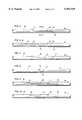
- FIG. 5is a side elevation of a catheter incorporating a step weld in accordance with the present invention.
- FIG. 5Ais a section taken along the line 5A--5A of FIG. 5;
- FIG. 6is a side elevation of a catheter incorporating a multi-step weld in accordance with the invention.
- FIG. 7is a side elevation of a catheter incorporating a shallow angle weld in accordance with the invention.
- FIG. 8is a side elevation of a catheter incorporating a steep angle weld in accordance with the invention.
- FIG. 9is a side elevation of a catheter incorporating a combination step/angle weld in accordance with the invention.
- FIG. 10is a side elevation of a catheter incorporating a combination step, angle and butt weld in accordance with the present invention.
- FIG. 11is a partial side elevation illustrating a catheter with multiple sections including a curved section incorporating a weld in accordance with the subject invention
- FIG. 12is a partial side elevation of a catheter in accordance with the invention.
- FIG. 13is a partial side elevation illustrating the manner in which the end of a wire reinforcement braid is secured to an inner layer of a catheter during the manufacturing process
- FIG. 14is a partial side elevation illustrating the manner in which a terminal tip is added to the forward end of the catheter during the manufacturing process
- FIG. 15is a side elevation of an assembled catheter in accordance with the process of this invention, prior to thermal processing.
- FIG. 16is a schematic side elevation illustrating the catheter of FIG. 15, covered with a shrink tube, ready for thermal processing.
- FIGS. 1 and 2represent a known catheter construction of the type disclosed in U.S. Pat. No. 5,254,107.
- the catheter assembly 10includes a conventional hub 12 at its proximal end, and a tubular catheter 14 extending from the hub 12 to a distal end 16.
- the cathetermay have a first axial section 18, a second axial section 20 and a distal tip section 22.
- the catheter 14comprises an inner tubular plastic layer 24, which may be made of fluoro polymers such as PTFE, FEP or other similar polymers.
- a second layer 26comprises a braided stainless steel tube applied by a conventional braiding machine.
- An outer, third layer 28 of plasticis then applied by suitable means over the braided layer.
- this outer layermay include two or more axial sections.
- the first axial section 18may be made of a plastic material such as nylon 12 with a Shore D durometer of 65-70.
- the second axial section 20may be nylon 12, and may have a Shore D durometer of 35-45.
- the transition tip 22may be made of polyurethane with a Shore A durometer of about 80.
- the adjacent axial sectionsare butt welded or fused together, such that the joints describe circles C1 and C2 perpendicular to the longitudinal axis of the catheter.
- the present inventionrelates to new and unique weld configurations for joining axial sections of the outer plastic layer of a catheter as generally described above.
- welds used in catheter constructionsare either of the butt type shown in FIGS. 1 and 2, or of the overlapping variety, typically known as "lap" welds as shown in FIGS. 4 and 4A (inner layer and braided layer removed for the sake of clarity).
- lap weldstypically known as “lap" welds as shown in FIGS. 4 and 4A (inner layer and braided layer removed for the sake of clarity).
- one tubular portion 30is received over a second tubular portion 32 and welded thereto, such that, in the weld area, a double thickness is created, as best seen in FIG. 4A.
- weldsare used to connect lengths of catheter tubing, which welds are designed to have substantial axial length, but without altering the outer diameter of the catheter.
- a first catheter length 34is connected to a second catheter length 36 by a step weld 38 which includes radial seam portions 40 and 42 and extended axial seam portions 44, 44A (see FIG. 4A).
- step weld 38which includes radial seam portions 40 and 42 and extended axial seam portions 44, 44A (see FIG. 4A).
- internal layershave been omitted simply for the sake of clarity.
- a multi-step weld 46axially joins catheter lengths 48 and 50, with the weld having three radial seam portions 52, 54 and 56 and two extended axial seam portions 58 and 60.
- a shallow angle weld 62axially joins catheter lengths 64 and 66. While no purely radial weld seam portions are formed in this arrangement, a single extended axial portion 68 gradually transitions along a shallow angle ⁇ .
- FIG. 8illustrates a variation in the weld configuration of FIG. 7, in that the weld 70 axially joining catheter lengths 72, 74 axially along a seam 76 which makes a relatively steep angle ⁇ .
- FIG. 9illustrates a hybrid weld 78 axially joining catheter lengths 80, 82 along a pair of angled seams 84, 86 connected by an extended axial seam 88.
- FIG. 10illustrates yet another hybrid weld 90 axially joining catheter lengths 92, 94.
- the weldincludes a radial seam portion 96 and an angled seam portion 98 connected by an extended axial seam portion 100.
- the above described weldsaxially join two lengths of catheter with a significant axial seam portion (at least about 0.5 cm. in axial length and preferably 0.5-10 cm.) but without altering the outside diameter (OD) of the catheter.
- the OD of the outer plastic layerdoes not change and, in no case are there double thicknesses as in lap welds.
- the weld seamsextend axially along the length of the catheter.
- the overall increased surface area of the welded jointsincreases the bond integrity between the two joined sections.
- the various weld configurationsalso create more desirable transitions between materials of different durometers, resins, etc. than typical butt or lap welded joints.
- the catheter shown in FIGS. 5 and 5Awith an axially extended overlap of from, e.g., 0.5 to 10 cm., a unique section of catheter is created where section 34 might be a hard durometer (e.g., 60-70 on the Shore D Scale) and section 36 a soft durometer (e.g., 25-50 Shore D Scale or even a very soft Shore A hardness), the combined axial section along the axial length of the weld has a stiffness which is the average of the two durometers.
- This ability to create lengths of catheter with different properties or characteristicsis most advantageous in areas of the catheter which will incorporate (or be bent into) curved areas.
- the length 34has a harder durometer--on the outside of the curve; while the length 36 has a softer durometer--on the inside of the curve.
- the weld overlap areahas a desirable stiffness which falls between the stiffness of the materials used to form sections 34 and 36, but in addition, unique curve retention properties are created by reason of the dominance of the harder durometer over the softer durometer.
- the softer durometermay be on the outside and the harder durometer on the inside of the curve.
- the axially overlapping sectionsmay be color coded.
- the different catheter lengthscan be of the same material (e.g., suitable resins) but have different durometers, or they can be of different materials of the same or different durometer.
- suitable resinsinclude Nylon 11 and Nylon 12; Pebaxe (25D to 70D); Nylon/Pebax® blends; polyurethanes (large durometer-infinite range); polyethylenes (high and low density); PVC; and other medical grade resins and various combinations of same.
- Typical catheter constructions as shown and described hereinmay be in the size range of 1-15 French (0.013" to about 0.200" I.D.).
- One or more inner layersmay include, for example, a conventional PTFE, FEP or similar liner reinforced by stainless steel braid.
- the invention hereis applicable, however, to a wide range of catheter types.
- diagnostic (angiography) and therapeutic (guiding) cathetersand other catheter technologies such as PTA, PTCA, electrophysiology, pacing leads, etc.
- Such cathetersas indicated above, may or may not include woven or braided reinforcements.
- Such reinforcements, if used,may comprise metal or synthetic materials including stainless steel, Kevlar®, etc.
- the cathetersmay be of single or multi-lumen design and may or may not have a Teflon® or other friction reducing lining.
- the cathetersmay or may not have a tapered distal portion and may or may not have side ports. While the catheter constructions illustrated herein show only a single weld per catheter, i.e., two axial sections, it should be understood that each catheter may have more than one welded area and may incorporate two or more different resins with the same or varying durometers.
- the transition portionsi.e., the axially extending portions of the weld
- a short transition weldhas a ratio of about 3:1 to about 12:1
- a long transition weldhas a ratio of about 12:1 to about 40:1.
- Short transition weldsprovide increased surface areas which strengthens the welded joints, and provide longer, less abrupt transition areas than simple butt welds. Such welds minimize the tendency of kinking and provide better torque transmission characteristics than conventional butt welds.
- Long transition weldsalso provide increased surface area for strengthening the welded joints. In addition, long transition welds produce more desirable feel and/or handling characteristics in use. The orientation of different materials in long transition welds provides ease of straightening and permits unique properties to be established within one or more curved areas of the catheter. Long transition welds also allow for greater differences in durometer.
- the catheterincludes three axial sections: a primary section 112, a secondary section 114, and a tertiary transition tip section 116.
- a terminal tip 118is also secured at the distal end of the catheter.
- the catheteralso includes an inner layer 120, preferably of Teflon®, and a stainless steel braid layer 122 sandwiched between the inner Teflon® layer 120 and the outer layer comprising jacket sections 112, 114 and 116 (see FIG. 13).
- the thin walled, highly lubricious inner Teflon® layer 120 in thin tubular formis loaded onto a generally rigid, preferably solid, ground stainless steel mandrel 124 of approximately 44" in length.
- the layer 120may have a wall thickness of about 0.0015", and the exterior surface thereof is etched.
- ultra spring temper stainless steel wireis braided onto a continuous length of a disposable (preferably plastic) mandrel (not shown).
- the braid densityis approximately 60-PIC, and the mandrel has a diameter which approximates the diameter of the Teflon® covered mandrel described above.
- the braided stockis cut to a length of approximately 44", and the disposable mandrel then removed.
- One end of the cut braided tube or layer 122is placed into an annealing fixture and, after annealing about a 1/2 inch section of the braided tube, the annealed section is cut so as to leave an annealed end of approximately 1/16" in length at one end of the braided tube 122.
- the braided tube 122is loaded onto the Teflon® covered mandrel, finally sliding the annealed end over the end of the mandrel 124 so that about 1 inch of Teflon® is left exposed (see FIG. 13).
- the 1/16" annealed end of the braided tube 122lies adjacent a 1 inch exposed end of the Teflon® layer 120. It has been found that by annealing the end of the braided tube, the cut ends thereof will lie flat, in a relaxed state, on the Teflon layer 120. Otherwise, the cut ends would tend to spring outwardly and not only inhibit loading of the axial jacket sections, but also potentially damage the latter as well.
- the annealed end of the wire braid layer or tube 122is anchored to the inner Teflon® layer 120 using a small, thin walled (0.002 inch) sleeve 126 of PEBA material. After the sleeve 126 is loaded onto the annealed end of the braided tube as shown in FIG. 13, a first shrink film or tube 128 is applied over the sleeve.
- the shrink filmwhich may be formed of FEP-Teflon®, is then heated to 385°-400° F. so that the compressive force during shrinking, combined with the heat inherent in the process, causes the PEBA sleeve 126 to melt into the interstices of the braided layer 122, at the same time that the cut end wires are being forced flat against the Teflon® layer 120. This results in the end wires being held neatly in place so that they will not be disturbed during the remainder of the assembly process.
- a length of soft tip material(which may be a softer PEBA material, e.g., a Shore D of about 30), in the form of a sleeve 130, is threaded over the end of the Teflon® inner layer so that it is in abutting contact with the annealed end of the braid layer as described above.
- a Teflon® tube 132may be press fit over the Teflon® inner layer and advanced until it butts up against the tip sleeve 130. This bumper will keep the tip in place during the remainder of the catheter processing, and will keep the tip material from flowing out of the forward end of the assembly during the remaining thermal processing described below.
- the first or primary jacket section 112(comprising the major length portion of the catheter) is formed in the exemplary embodiment from Nylon 12 with 30% BASO 4 .
- This first axial sectionmay have a length of approximately 80 cm. and forms the main shaft of the catheter.
- the secondary jacket 114is formed from PEBA with a Shore D durometer of 70 and approximately 30% BASO 4 .
- This secondary jackethas an axial length of about 25 cm. and forms what may be referred to as the Aortic curve section of the catheter.
- the tertiary jacket 116is formed from a soft PEBA with a Shore D durometer of 48 and approximately 30% BASO 4 . This tertiary jacket may have a length of about 7 cm. and forms the soft primary curve section of the catheter, also known as the transition tip.
- the jacket sections 112, 114 and 116are cut axially and loaded into the braided assembly (inner layer 120 and braid layer 122) as follows.
- the tertiary jacket 116is loaded onto the end of the braided assembly opposite the end with the annealed section of wire braid. This tertiary section 116 is moved along the braid layer 26 until it fully covers the annealed section of the braid, and contacts the tip stock sleeve 130.
- the secondary jacket 114is then loaded onto the braided assembly such that the weld seams are aligned (as shown, for example, in FIGS. 5-10 depending on the specific weld or combinations of welds used).
- the primary jacket section 112is then loaded onto the braid assembly in the same fashion.
- a second length of FEP shrink tube 134(see FIG. 15) of approximately 44 inches in length is placed over the entire catheter assembly, including the tip stock sleeve 130.
- the shrink tube usedis usually a 1.4:1 to 1.6:1 shrink ratio, with dimensions that may differ depending on the size of the catheter being made.
- the catheter assembly 136is then placed into an oven 138 (FIG. 16) or onto a conveyor which passes through a heated chamber.
- the FEP tube 134is shrunk, causing the now molten primary, secondary and tertiary jackets 112, 114 and 116 to compress into the interstices of the braid layer 122, and thus also contact and adhere to the etched surface of the Teflon® layer 120 as well.
- the FEP shrink tube 134is slit or perforated and peeled off the assembly, and the bumper 132 removed.
- the stainless steel mandrel 124is then removed from the internal diameter of the assembly.
- the terminal tip sleeve 130is then cut to a desired length (approximately 2 mm) and then, using any of a variety of conventional methods, reflowed such that the soft PEBA material flows beyond the end of the PTFE liner.
- the end of the PTFE liner 24is encapsulated by the small terminal tip 118 of PEBA material (see FIG. 12), thus forming the terminal tip.
- This soft tip 118will overlie the one inch exposed portion of the Teflon® layer 120 but it will not have any wire braid reinforcement.
- the end resultis a catheter shaft which has multiple durometer sections, continuous ultra spring stainless steel wire extending up to the soft tip, and a continuous Teflon® liner extending through the tip.
- the catheteralso contains the unique axially disposed welded sections as described earlier, imparting different properties to the catheter at the desired axial locations thereof, and particularly in the curved areas.
- the thin wall sleeve 126 utilized to hold the cut end wires of the braid layer 122 against the Teflon® layer 120is preferably formed of a high temperature thermoplastic material such as polyester ester.
- a high temperature thermoplastic materialsuch as polyester ester.
- One such materialis that available under the trade name ARNITEL, available from Dutch State Mines (DSM).
- DSMDutch State Mines
- the temperature utilized in the heat shrinking stepis gauged to the shrink tube properties, the temperature is raised to the melting temperature of the polyester ester (about 425° F.) in order to cause the sleeve to melt into the interstices of the braided layer 122. Except for the somewhat higher temperature, this step is essentially the same as explained hereinabove.
- the subsequent heat shrink step(utilizing the second FEP shrink tube 134) carried out after the three axial jacket sections 112, 114 and 116 have been loaded onto the braided assembly, is carried out as described hereinabove, and at the same temperature. Because, however, the polyester ester material has a higher melting temperature than the previously described PEBA material, the polyester ester does not remelt during this second heat shrink step.
- polyester esterfor the sleeve 126 is more effective in holding the end wires of the braid in place, flat against the Teflon® layer 120. By not remelting the polyester ester, the possibility of the braided wire ends becoming free and possibly protruding into the outer jacket is substantially eliminated.
- coextruded tubewhich contains different durometers and/or different material compositions in varying ratios at specific points along the tube, creating a gradual controllable change in section.
- a coextruded tubewhich contains a generally stiff material such as, but not limited to, nylon 12 and a considerably softer material such as, but not limited to, a Pebax® 55D.
- the tubemay have a wall thickness of 0.008 inches.
- the main length of the tubewhich could represent the shaft of the catheter, would have a 0.008 inch wall which has a 7:1 ratio of nylon to Pebax® 55D, respectively. At the specific point along the length of the tube, this ratio would be varied at a desired rate until the desired ratio of nylon to Pebax® 55D is achieved, at say, about 1:7. In this way, it is possible to form a monolithic tube with a constant wall thickness that has variable stiffness along its length. This monolithic tube could then become the jacket for the assembly in the process as otherwise described above.
Landscapes
- Health & Medical Sciences (AREA)
- Engineering & Computer Science (AREA)
- Life Sciences & Earth Sciences (AREA)
- Biomedical Technology (AREA)
- Pulmonology (AREA)
- Anesthesiology (AREA)
- Biophysics (AREA)
- Heart & Thoracic Surgery (AREA)
- Hematology (AREA)
- Animal Behavior & Ethology (AREA)
- General Health & Medical Sciences (AREA)
- Public Health (AREA)
- Veterinary Medicine (AREA)
- Mechanical Engineering (AREA)
- Media Introduction/Drainage Providing Device (AREA)
Abstract
Description
Claims (11)
Priority Applications (1)
| Application Number | Priority Date | Filing Date | Title |
|---|---|---|---|
| US08/979,549US5951929A (en) | 1995-12-12 | 1997-11-26 | Method for forming a catheter having overlapping welds |
Applications Claiming Priority (4)
| Application Number | Priority Date | Filing Date | Title |
|---|---|---|---|
| US08/570,941US5772641A (en) | 1995-12-12 | 1995-12-12 | Overlapping welds for catheter constructions |
| US59675996A | 1996-02-05 | 1996-02-05 | |
| US67356396A | 1996-07-01 | 1996-07-01 | |
| US08/979,549US5951929A (en) | 1995-12-12 | 1997-11-26 | Method for forming a catheter having overlapping welds |
Related Parent Applications (1)
| Application Number | Title | Priority Date | Filing Date |
|---|---|---|---|
| US67356396AContinuation | 1995-12-12 | 1996-07-01 |
Publications (1)
| Publication Number | Publication Date |
|---|---|
| US5951929Atrue US5951929A (en) | 1999-09-14 |
Family
ID=27416105
Family Applications (1)
| Application Number | Title | Priority Date | Filing Date |
|---|---|---|---|
| US08/979,549Expired - LifetimeUS5951929A (en) | 1995-12-12 | 1997-11-26 | Method for forming a catheter having overlapping welds |
Country Status (1)
| Country | Link |
|---|---|
| US (1) | US5951929A (en) |
Cited By (67)
| Publication number | Priority date | Publication date | Assignee | Title |
|---|---|---|---|---|
| US20030018293A1 (en)* | 2001-06-29 | 2003-01-23 | Allan Tanghoj | Catheter device |
| US20030060807A1 (en)* | 2001-09-24 | 2003-03-27 | Allan Tanghoj | Urinary catheter assembly allowing for non-contaminated insertion of the catheter into a urinary canal |
| US6575934B2 (en) | 2000-12-21 | 2003-06-10 | Advanced Cardiovascular Systems, Inc. | Low profile catheter |
| US20030195490A1 (en)* | 2000-05-25 | 2003-10-16 | Cook Incorporated | Medical device including unitary, continuous portion of varying durometer |
| US20040026819A1 (en)* | 2002-08-09 | 2004-02-12 | The Boeing Company | Post-forming of thermoplastic ducts |
| US6702972B1 (en) | 1998-06-09 | 2004-03-09 | Diametrics Medical Limited | Method of making a kink-resistant catheter |
| US6740073B1 (en) | 2000-12-06 | 2004-05-25 | Advanced Cardiovascular Systems, Inc. | Guiding catheter reinforcement with angled distal end |
| US20040140585A1 (en)* | 2003-01-17 | 2004-07-22 | Scimed Life Systems, Inc. | Methods of forming catheters with soft distal tips |
| US20040158231A1 (en)* | 2001-06-29 | 2004-08-12 | Allan Tanghoj | Catheter device |
| US20040163980A1 (en)* | 2001-06-29 | 2004-08-26 | Allan Tanghoj | Catheter assembly valve system |
| US20050010194A1 (en)* | 2003-07-09 | 2005-01-13 | Scimed Life Systems, Inc. | Method of forming catheter distal tip |
| US6921880B2 (en) | 2003-04-04 | 2005-07-26 | Constance F. Berger | Apparatus for heating bottles and method of manufacturing same |
| US6939337B2 (en) | 2000-07-14 | 2005-09-06 | Cook Incorporated | Medical device including tube having a braid and an expanded coil |
| US20050261666A1 (en)* | 2004-05-18 | 2005-11-24 | Blane Larson | Medical devices and methods of making the same |
| US6974557B1 (en)* | 2001-12-18 | 2005-12-13 | Advanced Cardiovasculer Systems, Inc. | Methods for forming an optical window for an intracorporeal device and for joining parts |
| US20060198976A1 (en)* | 2005-03-04 | 2006-09-07 | Trapp Benjamin M | Polymer shrink tubes and novel uses therefor |
| US7163523B2 (en) | 2003-02-26 | 2007-01-16 | Scimed Life Systems, Inc. | Balloon catheter |
| US20070167877A1 (en)* | 2006-01-17 | 2007-07-19 | Euteneuer Charles L | Medical catheters and methods |
| US20080077173A1 (en)* | 2006-09-25 | 2008-03-27 | Boston Scientific Scimed, Inc. | Designs for balloon welds |
| US20080097396A1 (en)* | 2006-05-30 | 2008-04-24 | Spencer Steven M | Medical devices and related systems and methods |
| US20080161774A1 (en)* | 2006-12-28 | 2008-07-03 | Hastings John M | Catheter with embedded components and method of its manufacture |
| US7704245B2 (en) | 2003-04-14 | 2010-04-27 | Cook Incorporated | Large diameter delivery catheter/sheath |
| US20100160862A1 (en)* | 2008-12-22 | 2010-06-24 | Cook Incorporated | Variable stiffness introducer sheath with transition zone |
| US7815599B2 (en) | 2004-12-10 | 2010-10-19 | Boston Scientific Scimed, Inc. | Catheter having an ultra soft tip and methods for making the same |
| US8088097B2 (en) | 2007-11-21 | 2012-01-03 | Glumetrics, Inc. | Use of an equilibrium intravascular sensor to achieve tight glycemic control |
| US8382724B2 (en) | 2005-03-04 | 2013-02-26 | C. R. Bard, Inc. | Systems and methods for radiographically identifying an access port |
| USD676955S1 (en) | 2010-12-30 | 2013-02-26 | C. R. Bard, Inc. | Implantable access port |
| US8382723B2 (en) | 2005-03-04 | 2013-02-26 | C. R. Bard, Inc. | Access port identification systems and methods |
| USD682416S1 (en) | 2010-12-30 | 2013-05-14 | C. R. Bard, Inc. | Implantable access port |
| US8467843B2 (en) | 2009-11-04 | 2013-06-18 | Glumetrics, Inc. | Optical sensor configuration for ratiometric correction of blood glucose measurement |
| US8475417B2 (en) | 2005-04-27 | 2013-07-02 | C. R. Bard, Inc. | Assemblies for identifying a power injectable access port |
| US8512245B2 (en) | 2008-04-17 | 2013-08-20 | Glumetrics, Inc. | Sensor for percutaneous intravascular deployment without an indwelling cannula |
| US20130228147A1 (en)* | 2010-09-02 | 2013-09-05 | Mahle International Gmbh | Hollow plastic piece |
| US8585950B2 (en) | 2009-01-29 | 2013-11-19 | Angiodynamics, Inc. | Multilumen catheters and method of manufacturing |
| US8608713B2 (en) | 1998-12-07 | 2013-12-17 | C. R. Bard, Inc. | Septum feature for identification of an access port |
| US8641676B2 (en) | 2005-04-27 | 2014-02-04 | C. R. Bard, Inc. | Infusion apparatuses and methods of use |
| US8708997B2 (en) | 2000-03-23 | 2014-04-29 | Cook Medical Technologies Llc | Introducer sheath |
| US8715589B2 (en) | 2009-09-30 | 2014-05-06 | Medtronic Minimed, Inc. | Sensors with thromboresistant coating |
| US8738107B2 (en) | 2007-05-10 | 2014-05-27 | Medtronic Minimed, Inc. | Equilibrium non-consuming fluorescence sensor for real time intravascular glucose measurement |
| US8838195B2 (en) | 2007-02-06 | 2014-09-16 | Medtronic Minimed, Inc. | Optical systems and methods for ratiometric measurement of blood glucose concentration |
| US8932271B2 (en) | 2008-11-13 | 2015-01-13 | C. R. Bard, Inc. | Implantable medical devices including septum-based indicators |
| US8998860B2 (en) | 2005-03-04 | 2015-04-07 | C. R. Bard, Inc. | Systems and methods for identifying an access port |
| US20150119862A1 (en)* | 2013-10-24 | 2015-04-30 | St. Jude Medical, Cardiology Division, Inc. | Flexible catheter shaft and method of manufacture |
| US9079004B2 (en) | 2009-11-17 | 2015-07-14 | C. R. Bard, Inc. | Overmolded access port including anchoring and identification features |
| US9265912B2 (en) | 2006-11-08 | 2016-02-23 | C. R. Bard, Inc. | Indicia informative of characteristics of insertable medical devices |
| US9474888B2 (en) | 2005-03-04 | 2016-10-25 | C. R. Bard, Inc. | Implantable access port including a sandwiched radiopaque insert |
| US9579496B2 (en) | 2007-11-07 | 2017-02-28 | C. R. Bard, Inc. | Radiopaque and septum-based indicators for a multi-lumen implantable port |
| US9585784B2 (en) | 2011-08-29 | 2017-03-07 | Coloplast A/S | Catheter activation by handle removal |
| US9603993B2 (en) | 2005-03-04 | 2017-03-28 | C. R. Bard, Inc. | Access port identification systems and methods |
| US9642986B2 (en) | 2006-11-08 | 2017-05-09 | C. R. Bard, Inc. | Resource information key for an insertable medical device |
| EP3263167A1 (en)* | 2016-06-30 | 2018-01-03 | Dentsply IH AB | Urinary catheter with varying properties |
| WO2018201055A1 (en) | 2017-04-28 | 2018-11-01 | Merit Medical Systems, Inc. | Introducer with partially annealed reinforcement element and related systems and methods |
| US10307581B2 (en) | 2005-04-27 | 2019-06-04 | C. R. Bard, Inc. | Reinforced septum for an implantable medical device |
| US10350382B1 (en) | 2018-06-08 | 2019-07-16 | Embolx, Inc. | High torque catheter and methods of manufacture |
| CN110785191A (en)* | 2017-06-21 | 2020-02-11 | 阿比奥梅德欧洲股份有限公司 | Cannula for intravascular blood pump |
| US10667822B2 (en) | 2013-05-08 | 2020-06-02 | Embolx, Inc. | Devices and methods for low pressure tumor embolization |
| US20200245944A1 (en)* | 2017-08-15 | 2020-08-06 | Cavis Technologies Ab | Pressure Catheter and Guide Wire Assembly |
| US10780252B2 (en) | 2016-02-16 | 2020-09-22 | Embolx, Inc. | Catheter with inflatable balloon |
| US11000670B2 (en) | 2003-04-28 | 2021-05-11 | Cook Medical Technologies Llc | Flexible sheath with varying durometer |
| US11123482B2 (en) | 2013-05-08 | 2021-09-21 | Embolx, Inc. | Device and methods for transvascular tumor embolization |
| US11172841B2 (en) | 2017-06-21 | 2021-11-16 | Alandra Medical SAPI DE CV | Electrode catheter assembly and method for the manufacture thereof |
| US11464948B2 (en) | 2016-02-16 | 2022-10-11 | Embolx, Inc. | Balloon catheters and methods of manufacture and use |
| US11890443B2 (en) | 2008-11-13 | 2024-02-06 | C. R. Bard, Inc. | Implantable medical devices including septum-based indicators |
| US12006156B1 (en) | 2023-02-06 | 2024-06-11 | COG Engineering Inc. | Systems and methods for heat processing |
| US12268824B2 (en) | 2018-07-27 | 2025-04-08 | Embolx, Inc. | Shaped catheter tip for tracking over a guidewire through turns in the vasculature |
| US12397129B2 (en) | 2015-07-30 | 2025-08-26 | Normedix, Inc. | Coronary guide catheter |
| US12409298B2 (en) | 2019-08-20 | 2025-09-09 | Embolx, Inc. | Catheters and methods of manufacture and use |
Citations (85)
| Publication number | Priority date | Publication date | Assignee | Title |
|---|---|---|---|---|
| US3924632A (en)* | 1972-12-07 | 1975-12-09 | William A Cook | Fiber glass reinforced catheter |
| US3945867A (en)* | 1973-11-05 | 1976-03-23 | William C. Heller, Jr. | Plastic hose making method |
| US3962153A (en)* | 1970-05-21 | 1976-06-08 | W. L. Gore & Associates, Inc. | Very highly stretched polytetrafluoroethylene and process therefor |
| US3965909A (en)* | 1975-04-22 | 1976-06-29 | Medrad, Inc. | Angiographic catheter and method of manufacture |
| US4044765A (en)* | 1975-12-17 | 1977-08-30 | Medical Evaluation Devices And Instruments Corporation | Flexible tube for intra-venous feeding |
| US4052989A (en)* | 1975-10-30 | 1977-10-11 | Medical Evaluation Devices And Instruments Corporation | Needle catheter |
| GB2043201A (en)* | 1979-02-19 | 1980-10-01 | Surgimed As | Method and apparatus for making tubular products such as catheters |
| US4305983A (en)* | 1978-09-21 | 1981-12-15 | Akzo Nv | Thin walled tubing formed of a melt spinnable synthetic polymer and process for the manufacturing thereof |
| US4323071A (en)* | 1978-04-24 | 1982-04-06 | Advanced Catheter Systems, Inc. | Vascular guiding catheter assembly and vascular dilating catheter assembly and a combination thereof and methods of making the same |
| US4347204A (en)* | 1978-12-19 | 1982-08-31 | Olympus Optical Co., Ltd. | Flexible tube and method of manufacturing same |
| GB2101680A (en)* | 1981-04-21 | 1983-01-19 | Thetford Compactors | Power-driven lids for refuse skips |
| US4385635A (en)* | 1980-04-25 | 1983-05-31 | Ruiz Oscar F | Angiographic catheter with soft tip end |
| US4391302A (en)* | 1979-01-27 | 1983-07-05 | Wolff Walsrode Aktiengesellschaft | Coupled tubular casing for foodstuffs |
| US4402684A (en)* | 1981-09-16 | 1983-09-06 | The Kendall Company | Cannula with soft tip |
| US4425919A (en)* | 1981-07-27 | 1984-01-17 | Raychem Corporation | Torque transmitting catheter apparatus |
| US4430282A (en)* | 1982-05-17 | 1984-02-07 | The Dow Chemical Company | Method for the extrusion of tetrafluoroethylene polymer tubes |
| US4430283A (en)* | 1980-11-13 | 1984-02-07 | The Dow Chemical Company | Method for the extrusion of tetrafluoroethylene polymer tubes |
| US4430083A (en)* | 1981-03-06 | 1984-02-07 | American Hospital Supply Corporation | Infusion catheter |
| US4447239A (en)* | 1979-03-19 | 1984-05-08 | Dr. Eduard Fresenius Chemisch-Pharmazeutishe Industry Kg | Catheter with radiographic contrast strips |
| US4464176A (en)* | 1982-06-04 | 1984-08-07 | Mallinckrodt, Inc. | Blood vessel catheter for medicine delivery and method of manufacture |
| US4517247A (en)* | 1982-05-21 | 1985-05-14 | Junkosha Co., Ltd. | Fluororesin formed body and method for producing the same |
| US4516972A (en)* | 1982-01-28 | 1985-05-14 | Advanced Cardiovascular Systems, Inc. | Guiding catheter and method of manufacture |
| US4531943A (en)* | 1983-08-08 | 1985-07-30 | Angiomedics Corporation | Catheter with soft deformable tip |
| US4547193A (en)* | 1984-04-05 | 1985-10-15 | Angiomedics Incorporated | Catheter having embedded multi-apertured film |
| GB2156680A (en)* | 1984-04-05 | 1985-10-16 | Angiomedics Inc | Method for forming a catheter with a soft deformable tip |
| US4563181A (en)* | 1983-02-18 | 1986-01-07 | Mallinckrodt, Inc. | Fused flexible tip catheter |
| US4577543A (en)* | 1983-08-18 | 1986-03-25 | American Hospital Supply Corporation | Construction of a monolithic reinforced catheter with flexible portions |
| US4580790A (en)* | 1984-06-21 | 1986-04-08 | Hughes Aircraft Company | Sintered polytetrafluoroethylene composite material and seal assembly |
| US4596563A (en)* | 1983-06-09 | 1986-06-24 | Cordis Corporation | Thin-walled multi-layered catheter having a fuseless tip |
| US4627844A (en)* | 1985-10-30 | 1986-12-09 | High Voltage Engineering Corporation | Tri-layer tubing |
| US4636346A (en)* | 1984-03-08 | 1987-01-13 | Cordis Corporation | Preparing guiding catheter |
| US4648892A (en)* | 1985-03-22 | 1987-03-10 | Massachusetts Institute Of Technology | Method for making optical shield for a laser catheter |
| US4662404A (en)* | 1981-05-15 | 1987-05-05 | Leveen Harry H | Flexible tubing |
| US4665604A (en)* | 1982-02-16 | 1987-05-19 | Cordis Corporation | Non-fused torque control catheter |
| US4690175A (en)* | 1981-11-17 | 1987-09-01 | Kabushiki Kaisha Medos Kenkyusho | Flexible tube for endoscope |
| US4764324A (en)* | 1983-12-12 | 1988-08-16 | Warren Burnham | Method of making a catheter |
| US4793351A (en)* | 1987-06-15 | 1988-12-27 | Mansfield Scientific, Inc. | Multi-lumen balloon catheter |
| US4813930A (en)* | 1987-10-13 | 1989-03-21 | Dimed, Inc. | Angioplasty guiding catheters and methods for performing angioplasty |
| US4817613A (en)* | 1987-07-13 | 1989-04-04 | Devices For Vascular Intervention, Inc. | Guiding catheter |
| US4836872A (en)* | 1987-11-02 | 1989-06-06 | Essex Group, Inc. | Method of manufacturing a fiber reinforced heat shrinkable tubing article |
| US4842590A (en)* | 1983-12-14 | 1989-06-27 | Terumo Kabushiki Kaisha | Catheter and method for making |
| US4861337A (en)* | 1988-03-02 | 1989-08-29 | Sherwood Medical Company | Collapsible urethral catheter |
| US4863442A (en)* | 1987-08-14 | 1989-09-05 | C. R. Bard, Inc. | Soft tip catheter |
| EP0334640A2 (en)* | 1988-03-25 | 1989-09-27 | BAXTER INTERNATIONAL INC. (a Delaware corporation) | Soft tip catheters |
| US4886506A (en)* | 1986-12-23 | 1989-12-12 | Baxter Travenol Laboratories, Inc. | Soft tip catheter |
| US4898591A (en)* | 1988-08-09 | 1990-02-06 | Mallinckrodt, Inc. | Nylon-PEBA copolymer catheter |
| US4898702A (en)* | 1988-04-04 | 1990-02-06 | Cordis Corporation | Method and apparatus for removal of a wire mandrel from a catheter |
| US4899787A (en)* | 1981-11-17 | 1990-02-13 | Kabushiki Kaisha Medos Kenkyusho | Flexible tube for endoscope |
| US4904431A (en)* | 1988-08-12 | 1990-02-27 | Baxter International, Inc. | Process for manufacturing catheters |
| US4925710A (en)* | 1988-03-31 | 1990-05-15 | Buck Thomas F | Ultrathin-wall fluoropolymer tube with removable fluoropolymer core |
| US5005587A (en)* | 1989-11-13 | 1991-04-09 | Pacing Systems, Inc. | Braid Electrode leads and catheters and methods for using the same |
| US5037404A (en)* | 1988-11-14 | 1991-08-06 | Cordis Corporation | Catheter having sections of variable torsion characteristics |
| US5049138A (en)* | 1989-11-13 | 1991-09-17 | Boston Scientific Corporation | Catheter with dissolvable tip |
| US5057092A (en)* | 1990-04-04 | 1991-10-15 | Webster Wilton W Jr | Braided catheter with low modulus warp |
| US5105819A (en)* | 1988-09-01 | 1992-04-21 | Kon-Tron Elektronik AG | Ultrasound endoscope device |
| US5147315A (en)* | 1990-04-06 | 1992-09-15 | C. R. Bard, Inc. | Access catheter and system for use in the female reproductive system |
| US5156155A (en)* | 1990-07-25 | 1992-10-20 | Hewlett-Packard Company | Transesophageal probe shaft |
| US5160559A (en)* | 1990-10-31 | 1992-11-03 | Scimed Life Systems, Inc. | Method for forming a guide catheter tip bond |
| US5171232A (en)* | 1989-06-13 | 1992-12-15 | Cordis Corporation | Catheter having highly radiopaque, flexible tip |
| US5207960A (en)* | 1990-05-30 | 1993-05-04 | Compagnie Plastic Omnium | Method for the manufacture of thin tubes of fluorinated resin, particularly of polytetrafluoroethylene |
| US5221270A (en)* | 1991-06-28 | 1993-06-22 | Cook Incorporated | Soft tip guiding catheter |
| US5221271A (en)* | 1991-08-15 | 1993-06-22 | Medex, Inc. | Sample site with flow directors |
| US5234416A (en)* | 1991-06-06 | 1993-08-10 | Advanced Cardiovascular Systems, Inc. | Intravascular catheter with a nontraumatic distal tip |
| US5254107A (en)* | 1991-03-06 | 1993-10-19 | Cordis Corporation | Catheter having extended braid reinforced transitional tip |
| US5279596A (en)* | 1990-07-27 | 1994-01-18 | Cordis Corporation | Intravascular catheter with kink resistant tip |
| US5308342A (en)* | 1991-08-07 | 1994-05-03 | Target Therapeutics, Inc. | Variable stiffness catheter |
| US5312356A (en)* | 1989-05-22 | 1994-05-17 | Target Therapeutics | Catheter with low-friction distal segment |
| US5318032A (en)* | 1992-02-05 | 1994-06-07 | Devices For Vascular Intervention | Guiding catheter having soft tip |
| US5336205A (en)* | 1993-02-25 | 1994-08-09 | Target Therapeutics, Inc. | Flow directed catheter |
| US5348536A (en)* | 1993-08-02 | 1994-09-20 | Quinton Instrument Company | Coextruded catheter and method of forming |
| US5358493A (en)* | 1993-02-18 | 1994-10-25 | Scimed Life Systems, Inc. | Vascular access catheter and methods for manufacture thereof |
| US5387199A (en)* | 1992-02-24 | 1995-02-07 | Baxter International Inc. | Polymer blends for torque transmitting catheters |
| US5401257A (en)* | 1993-04-27 | 1995-03-28 | Boston Scientific Corporation | Ureteral stents, drainage tubes and the like |
| US5403292A (en)* | 1994-05-18 | 1995-04-04 | Schneider (Usa) Inc. | Thin wall catheter having enhanced torqueability characteristics |
| WO1995013110A1 (en)* | 1993-11-12 | 1995-05-18 | Micro Interventional Systems | Small diameter, high torque catheter |
| WO1995015780A2 (en)* | 1993-12-10 | 1995-06-15 | Schneider (Usa) Inc. | Guiding catheter |
| US5441489A (en)* | 1989-04-13 | 1995-08-15 | Mitsubishi Cable Industries, Ltd. | Catheter with body temperature glass transition region |
| US5445624A (en)* | 1994-01-21 | 1995-08-29 | Exonix Research Corporation | Catheter with progressively compliant tip |
| US5484425A (en)* | 1990-05-01 | 1996-01-16 | Cathco, Inc. | Radiopaque non-kinking thin-walled introducer sheath |
| US5542937A (en)* | 1994-06-24 | 1996-08-06 | Target Therapeutics, Inc. | Multilumen extruded catheter |
| US5545151A (en)* | 1994-11-22 | 1996-08-13 | Schneider (Usa) Inc | Catheter having hydrophobic properties |
| US5545149A (en)* | 1993-06-25 | 1996-08-13 | Medtronic, Inc. | Method of catheter segment attachment |
| US5571073A (en)* | 1994-01-28 | 1996-11-05 | Cordis Corporation | Catheter flexible tip assembly |
| US5584821A (en)* | 1992-06-02 | 1996-12-17 | E-Z-Em, Inc. | Soft tip catheter |
| US5603705A (en)* | 1993-12-22 | 1997-02-18 | Scimed Life Systems, Inc. | Catheter joint with restraining device |
- 1997
- 1997-11-26USUS08/979,549patent/US5951929A/ennot_activeExpired - Lifetime
Patent Citations (89)
| Publication number | Priority date | Publication date | Assignee | Title |
|---|---|---|---|---|
| US3962153A (en)* | 1970-05-21 | 1976-06-08 | W. L. Gore & Associates, Inc. | Very highly stretched polytetrafluoroethylene and process therefor |
| US3924632A (en)* | 1972-12-07 | 1975-12-09 | William A Cook | Fiber glass reinforced catheter |
| US3945867A (en)* | 1973-11-05 | 1976-03-23 | William C. Heller, Jr. | Plastic hose making method |
| US3965909A (en)* | 1975-04-22 | 1976-06-29 | Medrad, Inc. | Angiographic catheter and method of manufacture |
| US4052989A (en)* | 1975-10-30 | 1977-10-11 | Medical Evaluation Devices And Instruments Corporation | Needle catheter |
| US4044765A (en)* | 1975-12-17 | 1977-08-30 | Medical Evaluation Devices And Instruments Corporation | Flexible tube for intra-venous feeding |
| US4323071A (en)* | 1978-04-24 | 1982-04-06 | Advanced Catheter Systems, Inc. | Vascular guiding catheter assembly and vascular dilating catheter assembly and a combination thereof and methods of making the same |
| US4323071B1 (en)* | 1978-04-24 | 1990-05-29 | Advanced Cardiovascular System | |
| US4305983A (en)* | 1978-09-21 | 1981-12-15 | Akzo Nv | Thin walled tubing formed of a melt spinnable synthetic polymer and process for the manufacturing thereof |
| US4347204A (en)* | 1978-12-19 | 1982-08-31 | Olympus Optical Co., Ltd. | Flexible tube and method of manufacturing same |
| US4391302A (en)* | 1979-01-27 | 1983-07-05 | Wolff Walsrode Aktiengesellschaft | Coupled tubular casing for foodstuffs |
| US4321226A (en)* | 1979-02-19 | 1982-03-23 | A/S Surgimed | Method and apparatus for making tubular products such as catheters |
| GB2043201A (en)* | 1979-02-19 | 1980-10-01 | Surgimed As | Method and apparatus for making tubular products such as catheters |
| US4447239A (en)* | 1979-03-19 | 1984-05-08 | Dr. Eduard Fresenius Chemisch-Pharmazeutishe Industry Kg | Catheter with radiographic contrast strips |
| US4385635A (en)* | 1980-04-25 | 1983-05-31 | Ruiz Oscar F | Angiographic catheter with soft tip end |
| US4430283A (en)* | 1980-11-13 | 1984-02-07 | The Dow Chemical Company | Method for the extrusion of tetrafluoroethylene polymer tubes |
| US4430083A (en)* | 1981-03-06 | 1984-02-07 | American Hospital Supply Corporation | Infusion catheter |
| GB2101680A (en)* | 1981-04-21 | 1983-01-19 | Thetford Compactors | Power-driven lids for refuse skips |
| US4662404A (en)* | 1981-05-15 | 1987-05-05 | Leveen Harry H | Flexible tubing |
| US4425919A (en)* | 1981-07-27 | 1984-01-17 | Raychem Corporation | Torque transmitting catheter apparatus |
| US4402684A (en)* | 1981-09-16 | 1983-09-06 | The Kendall Company | Cannula with soft tip |
| US4899787A (en)* | 1981-11-17 | 1990-02-13 | Kabushiki Kaisha Medos Kenkyusho | Flexible tube for endoscope |
| US4690175A (en)* | 1981-11-17 | 1987-09-01 | Kabushiki Kaisha Medos Kenkyusho | Flexible tube for endoscope |
| US4516972A (en)* | 1982-01-28 | 1985-05-14 | Advanced Cardiovascular Systems, Inc. | Guiding catheter and method of manufacture |
| US4665604A (en)* | 1982-02-16 | 1987-05-19 | Cordis Corporation | Non-fused torque control catheter |
| US4430282A (en)* | 1982-05-17 | 1984-02-07 | The Dow Chemical Company | Method for the extrusion of tetrafluoroethylene polymer tubes |
| US4517247A (en)* | 1982-05-21 | 1985-05-14 | Junkosha Co., Ltd. | Fluororesin formed body and method for producing the same |
| US4464176A (en)* | 1982-06-04 | 1984-08-07 | Mallinckrodt, Inc. | Blood vessel catheter for medicine delivery and method of manufacture |
| US4563181A (en)* | 1983-02-18 | 1986-01-07 | Mallinckrodt, Inc. | Fused flexible tip catheter |
| US4596563A (en)* | 1983-06-09 | 1986-06-24 | Cordis Corporation | Thin-walled multi-layered catheter having a fuseless tip |
| US4531943A (en)* | 1983-08-08 | 1985-07-30 | Angiomedics Corporation | Catheter with soft deformable tip |
| US4577543A (en)* | 1983-08-18 | 1986-03-25 | American Hospital Supply Corporation | Construction of a monolithic reinforced catheter with flexible portions |
| US4764324A (en)* | 1983-12-12 | 1988-08-16 | Warren Burnham | Method of making a catheter |
| US4842590A (en)* | 1983-12-14 | 1989-06-27 | Terumo Kabushiki Kaisha | Catheter and method for making |
| US4636346A (en)* | 1984-03-08 | 1987-01-13 | Cordis Corporation | Preparing guiding catheter |
| GB2156680A (en)* | 1984-04-05 | 1985-10-16 | Angiomedics Inc | Method for forming a catheter with a soft deformable tip |
| US4547193A (en)* | 1984-04-05 | 1985-10-15 | Angiomedics Incorporated | Catheter having embedded multi-apertured film |
| US4580790A (en)* | 1984-06-21 | 1986-04-08 | Hughes Aircraft Company | Sintered polytetrafluoroethylene composite material and seal assembly |
| US4648892A (en)* | 1985-03-22 | 1987-03-10 | Massachusetts Institute Of Technology | Method for making optical shield for a laser catheter |
| US4627844A (en)* | 1985-10-30 | 1986-12-09 | High Voltage Engineering Corporation | Tri-layer tubing |
| US4886506A (en)* | 1986-12-23 | 1989-12-12 | Baxter Travenol Laboratories, Inc. | Soft tip catheter |
| US4793351A (en)* | 1987-06-15 | 1988-12-27 | Mansfield Scientific, Inc. | Multi-lumen balloon catheter |
| US4817613A (en)* | 1987-07-13 | 1989-04-04 | Devices For Vascular Intervention, Inc. | Guiding catheter |
| US4863442A (en)* | 1987-08-14 | 1989-09-05 | C. R. Bard, Inc. | Soft tip catheter |
| US4813930A (en)* | 1987-10-13 | 1989-03-21 | Dimed, Inc. | Angioplasty guiding catheters and methods for performing angioplasty |
| US4836872A (en)* | 1987-11-02 | 1989-06-06 | Essex Group, Inc. | Method of manufacturing a fiber reinforced heat shrinkable tubing article |
| US4861337A (en)* | 1988-03-02 | 1989-08-29 | Sherwood Medical Company | Collapsible urethral catheter |
| EP0334640A2 (en)* | 1988-03-25 | 1989-09-27 | BAXTER INTERNATIONAL INC. (a Delaware corporation) | Soft tip catheters |
| US5078702A (en)* | 1988-03-25 | 1992-01-07 | Baxter International Inc. | Soft tip catheters |
| US4925710A (en)* | 1988-03-31 | 1990-05-15 | Buck Thomas F | Ultrathin-wall fluoropolymer tube with removable fluoropolymer core |
| US4898702A (en)* | 1988-04-04 | 1990-02-06 | Cordis Corporation | Method and apparatus for removal of a wire mandrel from a catheter |
| US4898591A (en)* | 1988-08-09 | 1990-02-06 | Mallinckrodt, Inc. | Nylon-PEBA copolymer catheter |
| US4904431A (en)* | 1988-08-12 | 1990-02-27 | Baxter International, Inc. | Process for manufacturing catheters |
| US5105819A (en)* | 1988-09-01 | 1992-04-21 | Kon-Tron Elektronik AG | Ultrasound endoscope device |
| US5037404A (en)* | 1988-11-14 | 1991-08-06 | Cordis Corporation | Catheter having sections of variable torsion characteristics |
| US5441489A (en)* | 1989-04-13 | 1995-08-15 | Mitsubishi Cable Industries, Ltd. | Catheter with body temperature glass transition region |
| US5312356A (en)* | 1989-05-22 | 1994-05-17 | Target Therapeutics | Catheter with low-friction distal segment |
| US5171232B1 (en)* | 1989-06-13 | 1997-10-28 | Cordis Corp | Catheter having highly radiopaque flexible tip |
| US5171232A (en)* | 1989-06-13 | 1992-12-15 | Cordis Corporation | Catheter having highly radiopaque, flexible tip |
| US5005587A (en)* | 1989-11-13 | 1991-04-09 | Pacing Systems, Inc. | Braid Electrode leads and catheters and methods for using the same |
| US5049138A (en)* | 1989-11-13 | 1991-09-17 | Boston Scientific Corporation | Catheter with dissolvable tip |
| US5057092A (en)* | 1990-04-04 | 1991-10-15 | Webster Wilton W Jr | Braided catheter with low modulus warp |
| US5147315A (en)* | 1990-04-06 | 1992-09-15 | C. R. Bard, Inc. | Access catheter and system for use in the female reproductive system |
| US5484425A (en)* | 1990-05-01 | 1996-01-16 | Cathco, Inc. | Radiopaque non-kinking thin-walled introducer sheath |
| US5207960A (en)* | 1990-05-30 | 1993-05-04 | Compagnie Plastic Omnium | Method for the manufacture of thin tubes of fluorinated resin, particularly of polytetrafluoroethylene |
| US5156155A (en)* | 1990-07-25 | 1992-10-20 | Hewlett-Packard Company | Transesophageal probe shaft |
| US5279596A (en)* | 1990-07-27 | 1994-01-18 | Cordis Corporation | Intravascular catheter with kink resistant tip |
| US5160559A (en)* | 1990-10-31 | 1992-11-03 | Scimed Life Systems, Inc. | Method for forming a guide catheter tip bond |
| US5254107A (en)* | 1991-03-06 | 1993-10-19 | Cordis Corporation | Catheter having extended braid reinforced transitional tip |
| US5234416A (en)* | 1991-06-06 | 1993-08-10 | Advanced Cardiovascular Systems, Inc. | Intravascular catheter with a nontraumatic distal tip |
| US5221270A (en)* | 1991-06-28 | 1993-06-22 | Cook Incorporated | Soft tip guiding catheter |
| US5308342A (en)* | 1991-08-07 | 1994-05-03 | Target Therapeutics, Inc. | Variable stiffness catheter |
| US5221271A (en)* | 1991-08-15 | 1993-06-22 | Medex, Inc. | Sample site with flow directors |
| US5318032A (en)* | 1992-02-05 | 1994-06-07 | Devices For Vascular Intervention | Guiding catheter having soft tip |
| US5387199A (en)* | 1992-02-24 | 1995-02-07 | Baxter International Inc. | Polymer blends for torque transmitting catheters |
| US5584821A (en)* | 1992-06-02 | 1996-12-17 | E-Z-Em, Inc. | Soft tip catheter |
| US5358493A (en)* | 1993-02-18 | 1994-10-25 | Scimed Life Systems, Inc. | Vascular access catheter and methods for manufacture thereof |
| US5336205A (en)* | 1993-02-25 | 1994-08-09 | Target Therapeutics, Inc. | Flow directed catheter |
| US5401257A (en)* | 1993-04-27 | 1995-03-28 | Boston Scientific Corporation | Ureteral stents, drainage tubes and the like |
| US5545149A (en)* | 1993-06-25 | 1996-08-13 | Medtronic, Inc. | Method of catheter segment attachment |
| US5348536A (en)* | 1993-08-02 | 1994-09-20 | Quinton Instrument Company | Coextruded catheter and method of forming |
| WO1995013110A1 (en)* | 1993-11-12 | 1995-05-18 | Micro Interventional Systems | Small diameter, high torque catheter |
| WO1995015780A2 (en)* | 1993-12-10 | 1995-06-15 | Schneider (Usa) Inc. | Guiding catheter |
| US5603705A (en)* | 1993-12-22 | 1997-02-18 | Scimed Life Systems, Inc. | Catheter joint with restraining device |
| US5445624A (en)* | 1994-01-21 | 1995-08-29 | Exonix Research Corporation | Catheter with progressively compliant tip |
| US5571073A (en)* | 1994-01-28 | 1996-11-05 | Cordis Corporation | Catheter flexible tip assembly |
| US5403292A (en)* | 1994-05-18 | 1995-04-04 | Schneider (Usa) Inc. | Thin wall catheter having enhanced torqueability characteristics |
| US5542937A (en)* | 1994-06-24 | 1996-08-06 | Target Therapeutics, Inc. | Multilumen extruded catheter |
| US5545151A (en)* | 1994-11-22 | 1996-08-13 | Schneider (Usa) Inc | Catheter having hydrophobic properties |
Cited By (162)
| Publication number | Priority date | Publication date | Assignee | Title |
|---|---|---|---|---|
| US6702972B1 (en) | 1998-06-09 | 2004-03-09 | Diametrics Medical Limited | Method of making a kink-resistant catheter |
| US8608713B2 (en) | 1998-12-07 | 2013-12-17 | C. R. Bard, Inc. | Septum feature for identification of an access port |
| US8708997B2 (en) | 2000-03-23 | 2014-04-29 | Cook Medical Technologies Llc | Introducer sheath |
| US9399114B2 (en) | 2000-03-23 | 2016-07-26 | Cook Medical Technologies LLC. | Introducer sheath |
| US20030195490A1 (en)* | 2000-05-25 | 2003-10-16 | Cook Incorporated | Medical device including unitary, continuous portion of varying durometer |
| US6881209B2 (en) | 2000-05-25 | 2005-04-19 | Cook Incorporated | Medical device including unitary, continuous portion of varying durometer |
| US7722795B2 (en) | 2000-05-25 | 2010-05-25 | Cook Incorporated And Sabin Corporation | Medical device including unitary, continuous portion of varying durometer |
| US6939337B2 (en) | 2000-07-14 | 2005-09-06 | Cook Incorporated | Medical device including tube having a braid and an expanded coil |
| US6740073B1 (en) | 2000-12-06 | 2004-05-25 | Advanced Cardiovascular Systems, Inc. | Guiding catheter reinforcement with angled distal end |
| US6575934B2 (en) | 2000-12-21 | 2003-06-10 | Advanced Cardiovascular Systems, Inc. | Low profile catheter |
| US8679092B2 (en) | 2001-06-29 | 2014-03-25 | Coloplast A/S | Catheter assembly |
| US20040254562A1 (en)* | 2001-06-29 | 2004-12-16 | Allan Tanghoj | Method of producing a catheter and a catheter |
| US8066693B2 (en) | 2001-06-29 | 2011-11-29 | Coloplast A/S | Catheter device |
| US20110213343A1 (en)* | 2001-06-29 | 2011-09-01 | Coloplast A/S | Catheter assembly |
| US20100204682A1 (en)* | 2001-06-29 | 2010-08-12 | Coloplast A/S | Catheter device |
| US20040158231A1 (en)* | 2001-06-29 | 2004-08-12 | Allan Tanghoj | Catheter device |
| US20040163980A1 (en)* | 2001-06-29 | 2004-08-26 | Allan Tanghoj | Catheter assembly valve system |
| US7682353B2 (en) | 2001-06-29 | 2010-03-23 | Coloplast A/S | Catheter device |
| US20080027414A1 (en)* | 2001-06-29 | 2008-01-31 | Coloplast A/S | Method of producing a catheter and a catheter |
| US8986286B2 (en) | 2001-06-29 | 2015-03-24 | Coloplast A/S | Catheter device |
| US7517343B2 (en) | 2001-06-29 | 2009-04-14 | Coloplast A/S | Catheter assembly |
| US20030018293A1 (en)* | 2001-06-29 | 2003-01-23 | Allan Tanghoj | Catheter device |
| US10441454B2 (en) | 2001-06-29 | 2019-10-15 | Coloplast A/S | Urinary catheter provided as a package |
| US7922712B2 (en) | 2001-09-24 | 2011-04-12 | Coloplast A/S | Urinary catheter assembly allowing for non-contaminated insertion of the catheter into a urinary canal |
| US20030060807A1 (en)* | 2001-09-24 | 2003-03-27 | Allan Tanghoj | Urinary catheter assembly allowing for non-contaminated insertion of the catheter into a urinary canal |
| US20080319423A1 (en)* | 2001-09-24 | 2008-12-25 | Coloplast A/S (Reel 012442, Frame 0712) | Urinary catheter assembly allowing for non-contaminated insertion of the catheter into a urinary canal |
| US7311698B2 (en) | 2001-09-24 | 2007-12-25 | Coloplast A/S | Urinary catheter assembly allowing for non-contaminated insertion of the catheter into a urinary canal |
| US20060106287A1 (en)* | 2001-12-18 | 2006-05-18 | Webler William E | Optical window for an intracorporeal device |
| US6974557B1 (en)* | 2001-12-18 | 2005-12-13 | Advanced Cardiovasculer Systems, Inc. | Methods for forming an optical window for an intracorporeal device and for joining parts |
| US20070013105A1 (en)* | 2002-08-09 | 2007-01-18 | The Boeing Company | Post-Forming of Thermoplastic Ducts |
| US20040026819A1 (en)* | 2002-08-09 | 2004-02-12 | The Boeing Company | Post-forming of thermoplastic ducts |
| US7128558B2 (en) | 2002-08-09 | 2006-10-31 | The Boeing Company | Post-forming of thermoplastic ducts |
| EP1388409A3 (en)* | 2002-08-09 | 2004-05-19 | The Boeing Company | Apparatus and method for post-forming thermoplastic ducts |
| US7322988B2 (en) | 2003-01-17 | 2008-01-29 | Boston Scientific Scimed, Inc. | Methods of forming catheters with soft distal tips |
| US20040140585A1 (en)* | 2003-01-17 | 2004-07-22 | Scimed Life Systems, Inc. | Methods of forming catheters with soft distal tips |
| US7163523B2 (en) | 2003-02-26 | 2007-01-16 | Scimed Life Systems, Inc. | Balloon catheter |
| US6921880B2 (en) | 2003-04-04 | 2005-07-26 | Constance F. Berger | Apparatus for heating bottles and method of manufacturing same |
| US7704245B2 (en) | 2003-04-14 | 2010-04-27 | Cook Incorporated | Large diameter delivery catheter/sheath |
| US7968038B2 (en) | 2003-04-14 | 2011-06-28 | Cook Medical Technologies Llc | Large diameter delivery catheter/sheath |
| US11000670B2 (en) | 2003-04-28 | 2021-05-11 | Cook Medical Technologies Llc | Flexible sheath with varying durometer |
| WO2005004969A1 (en)* | 2003-07-09 | 2005-01-20 | Boston Scientific Limited | Method of forming catheter distal tip |
| US20050010194A1 (en)* | 2003-07-09 | 2005-01-13 | Scimed Life Systems, Inc. | Method of forming catheter distal tip |
| US7597830B2 (en)* | 2003-07-09 | 2009-10-06 | Boston Scientific Scimed, Inc. | Method of forming catheter distal tip |
| US20050261666A1 (en)* | 2004-05-18 | 2005-11-24 | Blane Larson | Medical devices and methods of making the same |
| US8192569B2 (en) | 2004-05-18 | 2012-06-05 | Boston Scientific Scimed, Inc. | Medical devices and methods of making the same |
| US7815624B2 (en) | 2004-05-18 | 2010-10-19 | Boston Scientific Scimed, Inc. | Medical devices and methods of making the same |
| US20110030876A1 (en)* | 2004-05-18 | 2011-02-10 | Boston Scientific Scimed, Inc. | Medical devices and methods of making the same |
| US8973239B2 (en) | 2004-12-10 | 2015-03-10 | Boston Scientific Scimed, Inc. | Catheter having an ultra soft tip and methods for making the same |
| US7815599B2 (en) | 2004-12-10 | 2010-10-19 | Boston Scientific Scimed, Inc. | Catheter having an ultra soft tip and methods for making the same |
| US10265512B2 (en) | 2005-03-04 | 2019-04-23 | Bard Peripheral Vascular, Inc. | Implantable access port including a sandwiched radiopaque insert |
| US20080300577A1 (en)* | 2005-03-04 | 2008-12-04 | Trapp Benjamin M | Polymer shrink tubes and novel uses therefor |
| US20100198193A1 (en)* | 2005-03-04 | 2010-08-05 | Trapp Benjamin M | Polymer shrink tubes and novel uses therefor |
| US9682186B2 (en) | 2005-03-04 | 2017-06-20 | C. R. Bard, Inc. | Access port identification systems and methods |
| US20100193106A1 (en)* | 2005-03-04 | 2010-08-05 | Trapp Benjamin M | Polymer shrink tubes and novel uses therefor |
| AU2006221013B2 (en)* | 2005-03-04 | 2010-07-29 | W. L. Gore & Associates, Inc. | Polymer shrink tubes and novel uses therefor |
| US10675401B2 (en) | 2005-03-04 | 2020-06-09 | Bard Peripheral Vascular, Inc. | Access port identification systems and methods |
| US9603992B2 (en) | 2005-03-04 | 2017-03-28 | C. R. Bard, Inc. | Access port identification systems and methods |
| US8252219B2 (en) | 2005-03-04 | 2012-08-28 | W. L. Gore & Associates, Inc. | Polymer shrink tubes and novel uses therefor |
| US9603993B2 (en) | 2005-03-04 | 2017-03-28 | C. R. Bard, Inc. | Access port identification systems and methods |
| US8382724B2 (en) | 2005-03-04 | 2013-02-26 | C. R. Bard, Inc. | Systems and methods for radiographically identifying an access port |
| EP2311507A1 (en)* | 2005-03-04 | 2011-04-20 | Gore Enterprise Holdings, Inc. | Polymer shrink tubes and novel uses therefor |
| US8382723B2 (en) | 2005-03-04 | 2013-02-26 | C. R. Bard, Inc. | Access port identification systems and methods |
| US9474888B2 (en) | 2005-03-04 | 2016-10-25 | C. R. Bard, Inc. | Implantable access port including a sandwiched radiopaque insert |
| US9320831B2 (en) | 2005-03-04 | 2016-04-26 | W. L. Gore & Associates, Inc. | Polymer shrink tubes and novel uses therefor |
| US11077291B2 (en) | 2005-03-04 | 2021-08-03 | Bard Peripheral Vascular, Inc. | Implantable access port including a sandwiched radiopaque insert |
| WO2006096314A3 (en)* | 2005-03-04 | 2007-01-11 | Gore Enterprise Holdings Inc | Polymer shrink tubes and novel uses therefor |
| US10857340B2 (en) | 2005-03-04 | 2020-12-08 | Bard Peripheral Vascular, Inc. | Systems and methods for radiographically identifying an access port |
| US10905868B2 (en) | 2005-03-04 | 2021-02-02 | Bard Peripheral Vascular, Inc. | Systems and methods for radiographically identifying an access port |
| US10179230B2 (en) | 2005-03-04 | 2019-01-15 | Bard Peripheral Vascular, Inc. | Systems and methods for radiographically identifying an access port |
| US8998860B2 (en) | 2005-03-04 | 2015-04-07 | C. R. Bard, Inc. | Systems and methods for identifying an access port |
| US8585663B2 (en) | 2005-03-04 | 2013-11-19 | C. R. Bard, Inc. | Access port identification systems and methods |
| US8603052B2 (en) | 2005-03-04 | 2013-12-10 | C. R. Bard, Inc. | Access port identification systems and methods |
| US7736571B2 (en) | 2005-03-04 | 2010-06-15 | Gore Enterprise Holdings, Inc. | Polymer shrink tubes and novel uses therefor |
| US8939947B2 (en) | 2005-03-04 | 2015-01-27 | C. R. Bard, Inc. | Systems and methods for radiographically identifying an access port |
| US20060198976A1 (en)* | 2005-03-04 | 2006-09-07 | Trapp Benjamin M | Polymer shrink tubes and novel uses therefor |
| US10238850B2 (en) | 2005-03-04 | 2019-03-26 | Bard Peripheral Vascular, Inc. | Systems and methods for radiographically identifying an access port |
| US10052470B2 (en) | 2005-04-27 | 2018-08-21 | Bard Peripheral Vascular, Inc. | Assemblies for identifying a power injectable access port |
| US10625065B2 (en) | 2005-04-27 | 2020-04-21 | Bard Peripheral Vascular, Inc. | Assemblies for identifying a power injectable access port |
| US10780257B2 (en) | 2005-04-27 | 2020-09-22 | Bard Peripheral Vascular, Inc. | Assemblies for identifying a power injectable access port |
| US9937337B2 (en) | 2005-04-27 | 2018-04-10 | C. R. Bard, Inc. | Assemblies for identifying a power injectable access port |
| US10661068B2 (en) | 2005-04-27 | 2020-05-26 | Bard Peripheral Vascular, Inc. | Assemblies for identifying a power injectable access port |
| US8641688B2 (en) | 2005-04-27 | 2014-02-04 | C. R. Bard, Inc. | Assemblies for identifying a power injectable access port |
| US8641676B2 (en) | 2005-04-27 | 2014-02-04 | C. R. Bard, Inc. | Infusion apparatuses and methods of use |
| US10016585B2 (en) | 2005-04-27 | 2018-07-10 | Bard Peripheral Vascular, Inc. | Assemblies for identifying a power injectable access port |
| US10183157B2 (en) | 2005-04-27 | 2019-01-22 | Bard Peripheral Vascular, Inc. | Assemblies for identifying a power injectable access port |
| US9421352B2 (en) | 2005-04-27 | 2016-08-23 | C. R. Bard, Inc. | Infusion apparatuses and methods of use |
| US10307581B2 (en) | 2005-04-27 | 2019-06-04 | C. R. Bard, Inc. | Reinforced septum for an implantable medical device |
| US8545460B2 (en) | 2005-04-27 | 2013-10-01 | C. R. Bard, Inc. | Infusion apparatuses and related methods |
| US8475417B2 (en) | 2005-04-27 | 2013-07-02 | C. R. Bard, Inc. | Assemblies for identifying a power injectable access port |
| US20070167877A1 (en)* | 2006-01-17 | 2007-07-19 | Euteneuer Charles L | Medical catheters and methods |
| US20080097396A1 (en)* | 2006-05-30 | 2008-04-24 | Spencer Steven M | Medical devices and related systems and methods |
| US7718106B2 (en) | 2006-05-30 | 2010-05-18 | Boston Scientific Scimed, Inc. | Medical devices and related systems and methods |
| US8382709B2 (en) | 2006-09-25 | 2013-02-26 | Boston Scientific Scimed, Inc. | Designs for balloon welds |
| US20080077173A1 (en)* | 2006-09-25 | 2008-03-27 | Boston Scientific Scimed, Inc. | Designs for balloon welds |
| US10556090B2 (en) | 2006-11-08 | 2020-02-11 | C. R. Bard, Inc. | Resource information key for an insertable medical device |
| US9265912B2 (en) | 2006-11-08 | 2016-02-23 | C. R. Bard, Inc. | Indicia informative of characteristics of insertable medical devices |
| US10092725B2 (en) | 2006-11-08 | 2018-10-09 | C. R. Bard, Inc. | Resource information key for an insertable medical device |
| US9642986B2 (en) | 2006-11-08 | 2017-05-09 | C. R. Bard, Inc. | Resource information key for an insertable medical device |
| US20080161774A1 (en)* | 2006-12-28 | 2008-07-03 | Hastings John M | Catheter with embedded components and method of its manufacture |
| US7993481B2 (en) | 2006-12-28 | 2011-08-09 | St. Jude Medical, Atrial Fibrillation Division, Inc. | Catheter with embedded components and method of its manufacture |
| US9839378B2 (en) | 2007-02-06 | 2017-12-12 | Medtronic Minimed, Inc. | Optical systems and methods for ratiometric measurement of blood glucose concentration |
| US8838195B2 (en) | 2007-02-06 | 2014-09-16 | Medtronic Minimed, Inc. | Optical systems and methods for ratiometric measurement of blood glucose concentration |
| US8738107B2 (en) | 2007-05-10 | 2014-05-27 | Medtronic Minimed, Inc. | Equilibrium non-consuming fluorescence sensor for real time intravascular glucose measurement |
| US10086186B2 (en) | 2007-11-07 | 2018-10-02 | C. R. Bard, Inc. | Radiopaque and septum-based indicators for a multi-lumen implantable port |
| US11638810B2 (en) | 2007-11-07 | 2023-05-02 | C. R. Bard, Inc. | Radiopaque and septum-based indicators for a multi-lumen implantable port |
| US10792485B2 (en) | 2007-11-07 | 2020-10-06 | C. R. Bard, Inc. | Radiopaque and septum-based indicators for a multi-lumen implantable port |
| US9579496B2 (en) | 2007-11-07 | 2017-02-28 | C. R. Bard, Inc. | Radiopaque and septum-based indicators for a multi-lumen implantable port |
| US8979790B2 (en) | 2007-11-21 | 2015-03-17 | Medtronic Minimed, Inc. | Use of an equilibrium sensor to monitor glucose concentration |
| US8088097B2 (en) | 2007-11-21 | 2012-01-03 | Glumetrics, Inc. | Use of an equilibrium intravascular sensor to achieve tight glycemic control |
| US8535262B2 (en) | 2007-11-21 | 2013-09-17 | Glumetrics, Inc. | Use of an equilibrium intravascular sensor to achieve tight glycemic control |
| US8512245B2 (en) | 2008-04-17 | 2013-08-20 | Glumetrics, Inc. | Sensor for percutaneous intravascular deployment without an indwelling cannula |
| US10773066B2 (en) | 2008-11-13 | 2020-09-15 | C. R. Bard, Inc. | Implantable medical devices including septum-based indicators |
| US8932271B2 (en) | 2008-11-13 | 2015-01-13 | C. R. Bard, Inc. | Implantable medical devices including septum-based indicators |
| US10052471B2 (en) | 2008-11-13 | 2018-08-21 | C. R. Bard, Inc. | Implantable medical devices including septum-based indicators |
| US11890443B2 (en) | 2008-11-13 | 2024-02-06 | C. R. Bard, Inc. | Implantable medical devices including septum-based indicators |
| US20100160862A1 (en)* | 2008-12-22 | 2010-06-24 | Cook Incorporated | Variable stiffness introducer sheath with transition zone |
| US8585950B2 (en) | 2009-01-29 | 2013-11-19 | Angiodynamics, Inc. | Multilumen catheters and method of manufacturing |
| US8715589B2 (en) | 2009-09-30 | 2014-05-06 | Medtronic Minimed, Inc. | Sensors with thromboresistant coating |
| US8467843B2 (en) | 2009-11-04 | 2013-06-18 | Glumetrics, Inc. | Optical sensor configuration for ratiometric correction of blood glucose measurement |
| US8700115B2 (en) | 2009-11-04 | 2014-04-15 | Glumetrics, Inc. | Optical sensor configuration for ratiometric correction of glucose measurement |
| US9248268B2 (en) | 2009-11-17 | 2016-02-02 | C. R. Bard, Inc. | Overmolded access port including anchoring and identification features |
| US11759615B2 (en) | 2009-11-17 | 2023-09-19 | Bard Peripheral Vascular, Inc. | Overmolded access port including anchoring and identification features |
| US10155101B2 (en) | 2009-11-17 | 2018-12-18 | Bard Peripheral Vascular, Inc. | Overmolded access port including anchoring and identification features |
| US9079004B2 (en) | 2009-11-17 | 2015-07-14 | C. R. Bard, Inc. | Overmolded access port including anchoring and identification features |
| US10912935B2 (en) | 2009-11-17 | 2021-02-09 | Bard Peripheral Vascular, Inc. | Method for manufacturing a power-injectable access port |
| US9717895B2 (en) | 2009-11-17 | 2017-08-01 | C. R. Bard, Inc. | Overmolded access port including anchoring and identification features |
| US20130228147A1 (en)* | 2010-09-02 | 2013-09-05 | Mahle International Gmbh | Hollow plastic piece |
| US9249763B2 (en)* | 2010-09-02 | 2016-02-02 | Mahle International Gmbh | Hollow plastic piece |
| USD682416S1 (en) | 2010-12-30 | 2013-05-14 | C. R. Bard, Inc. | Implantable access port |
| USD676955S1 (en) | 2010-12-30 | 2013-02-26 | C. R. Bard, Inc. | Implantable access port |
| US9585784B2 (en) | 2011-08-29 | 2017-03-07 | Coloplast A/S | Catheter activation by handle removal |
| US11123482B2 (en) | 2013-05-08 | 2021-09-21 | Embolx, Inc. | Device and methods for transvascular tumor embolization |
| US10667822B2 (en) | 2013-05-08 | 2020-06-02 | Embolx, Inc. | Devices and methods for low pressure tumor embolization |
| US9999748B2 (en)* | 2013-10-24 | 2018-06-19 | St. Jude Medical, Cardiology Division, Inc. | Flexible catheter shaft and method of manufacture |
| US20150119862A1 (en)* | 2013-10-24 | 2015-04-30 | St. Jude Medical, Cardiology Division, Inc. | Flexible catheter shaft and method of manufacture |
| US12397129B2 (en) | 2015-07-30 | 2025-08-26 | Normedix, Inc. | Coronary guide catheter |
| US10780252B2 (en) | 2016-02-16 | 2020-09-22 | Embolx, Inc. | Catheter with inflatable balloon |
| US10786660B2 (en) | 2016-02-16 | 2020-09-29 | Embolx, Inc. | Occlusion balloon catheter and methods of fabrication and use |
| US11464948B2 (en) | 2016-02-16 | 2022-10-11 | Embolx, Inc. | Balloon catheters and methods of manufacture and use |
| AU2017291162B2 (en)* | 2016-06-30 | 2022-02-17 | Dentsply Ih Ab | Urinary catheter with varying properties |
| JP2019524198A (en)* | 2016-06-30 | 2019-09-05 | デントスプリー・アイエイチ・エービーDentsply Ih Ab | Urinary catheter with changing properties |
| EP3263167A1 (en)* | 2016-06-30 | 2018-01-03 | Dentsply IH AB | Urinary catheter with varying properties |
| CN109475719A (en)* | 2016-06-30 | 2019-03-15 | 登士伯Ih有限公司 | Urinary catheters with varying properties |
| WO2018001968A1 (en)* | 2016-06-30 | 2018-01-04 | Dentsply Ih Ab | Urinary catheter with varying properties |
| US10974025B2 (en) | 2016-06-30 | 2021-04-13 | Dentsply Ih Ab | Urinary catheter with varying properties |
| KR20190026812A (en)* | 2016-06-30 | 2019-03-13 | 덴츠플라이 아이에이치 에이비 | Catheter catheters with varying characteristics |
| US11191566B2 (en)* | 2017-04-28 | 2021-12-07 | Merit Medical Systems, Inc. | Introducer with partially annealed reinforcement element and related systems and methods |
| CN110678219A (en)* | 2017-04-28 | 2020-01-10 | 美国医疗设备有限公司 | Interposer with partially annealed reinforcement element and related systems and methods |
| US12076046B2 (en)* | 2017-04-28 | 2024-09-03 | Merit Medical Systems, Inc. | Introducer with partially annealed reinforcement element and related systems and methods |
| WO2018201055A1 (en) | 2017-04-28 | 2018-11-01 | Merit Medical Systems, Inc. | Introducer with partially annealed reinforcement element and related systems and methods |
| US20220087712A1 (en)* | 2017-04-28 | 2022-03-24 | Merit Medical Systems, Inc. | Introducer with partially annealed reinforcement element and related systems and methods |
| US20180310957A1 (en)* | 2017-04-28 | 2018-11-01 | Merit Medical Systems, Inc. | Introducer with partially annealed reinforcement element and related systems and methods |
| EP3615122A4 (en)* | 2017-04-28 | 2021-02-17 | Merit Medical Systems, Inc. | INTRODUCTORY DEVICE WITH PARTLY ANNUAL REINFORCEMENT ELEMENT AND ASSOCIATED SYSTEMS AND PROCESSES |
| US11752322B2 (en) | 2017-06-21 | 2023-09-12 | Abiomed Europe Gmbh | Cannula for intravascular blood pump |
| US11172841B2 (en) | 2017-06-21 | 2021-11-16 | Alandra Medical SAPI DE CV | Electrode catheter assembly and method for the manufacture thereof |
| CN110785191A (en)* | 2017-06-21 | 2020-02-11 | 阿比奥梅德欧洲股份有限公司 | Cannula for intravascular blood pump |
| US11839492B2 (en)* | 2017-08-15 | 2023-12-12 | Cavis Technologies Ab | Pressure catheter and guide wire assembly |
| US20200245944A1 (en)* | 2017-08-15 | 2020-08-06 | Cavis Technologies Ab | Pressure Catheter and Guide Wire Assembly |
| US10350382B1 (en) | 2018-06-08 | 2019-07-16 | Embolx, Inc. | High torque catheter and methods of manufacture |
| US12268824B2 (en) | 2018-07-27 | 2025-04-08 | Embolx, Inc. | Shaped catheter tip for tracking over a guidewire through turns in the vasculature |
| US12409298B2 (en) | 2019-08-20 | 2025-09-09 | Embolx, Inc. | Catheters and methods of manufacture and use |
| US12006156B1 (en) | 2023-02-06 | 2024-06-11 | COG Engineering Inc. | Systems and methods for heat processing |
Similar Documents
| Publication | Publication Date | Title |
|---|---|---|
| US5951929A (en) | Method for forming a catheter having overlapping welds | |
| US6103037A (en) | Method for making a catheter having overlapping welds | |
| US6197015B1 (en) | Angiography catheter with sections having different mechanical properties | |
| US5772641A (en) | Overlapping welds for catheter constructions | |
| US5545149A (en) | Method of catheter segment attachment | |
| EP0758258B1 (en) | Soft tip attachment for thin walled catheters | |
| US5811043A (en) | Method of soft tip forming | |
| US5711909A (en) | Intravascular catheter and method of manufacturing | |
| US7331948B2 (en) | Catheter and catheter fabrication method | |
| CA2204932C (en) | Intravascular catheter | |
| US10099036B2 (en) | Steerable catheter using flat pull wires and having torque transfer layer made of braided flat wires | |
| US5558737A (en) | Method of welding a tip to a catheter | |
| US5254107A (en) | Catheter having extended braid reinforced transitional tip | |
| US8585858B2 (en) | Medical catheter with bump tubing proximal segment | |
| US6187130B1 (en) | Method of creating a tip on a catheter | |
| US20160114133A1 (en) | Catheter and Method of Manufacture | |
| JP2000185103A (en) | Guide catheter with soft tip and method of manufacturing the same | |
| WO1998050098A1 (en) | Improved multi-durometer catheter | |
| US20250170307A1 (en) | Low friction and flexible catheter liner |
Legal Events
| Date | Code | Title | Description |
|---|---|---|---|
| STCF | Information on status: patent grant | Free format text:PATENTED CASE | |
| AS | Assignment | Owner name:JOMED GMBH, GERMANY Free format text:ASSIGNMENT OF ASSIGNORS INTEREST;ASSIGNOR:MEDI-DYNE, INC.;REEL/FRAME:011551/0745 Effective date:20010216 | |
| FEPP | Fee payment procedure | Free format text:PAYOR NUMBER ASSIGNED (ORIGINAL EVENT CODE: ASPN); ENTITY STATUS OF PATENT OWNER: LARGE ENTITY | |
| FPAY | Fee payment | Year of fee payment:4 | |
| FEPP | Fee payment procedure | Free format text:PAT HOLDER NO LONGER CLAIMS SMALL ENTITY STATUS, ENTITY STATUS SET TO UNDISCOUNTED (ORIGINAL EVENT CODE: STOL); ENTITY STATUS OF PATENT OWNER: LARGE ENTITY | |
| REFU | Refund | Free format text:REFUND - PAYMENT OF MAINTENANCE FEE, 8TH YR, SMALL ENTITY (ORIGINAL EVENT CODE: R2552); ENTITY STATUS OF PATENT OWNER: LARGE ENTITY | |
| FPAY | Fee payment | Year of fee payment:8 | |
| FPAY | Fee payment | Year of fee payment:12 | |
| AS | Assignment | Owner name:MEDI-DYNE INC., NEW YORK Free format text:ASSIGNMENT OF ASSIGNORS INTEREST;ASSIGNOR:WILSON, JAMES C.;REEL/FRAME:047951/0578 Effective date:19960625 |