US5951553A - Methods and apparatus for fusionless treatment of spinal deformities - Google Patents
Methods and apparatus for fusionless treatment of spinal deformitiesDownload PDFInfo
- Publication number
- US5951553A US5951553AUS08/892,604US89260497AUS5951553AUS 5951553 AUS5951553 AUS 5951553AUS 89260497 AUS89260497 AUS 89260497AUS 5951553 AUS5951553 AUS 5951553A
- Authority
- US
- United States
- Prior art keywords
- staple
- vertebral body
- prongs
- wedge member
- plate portion
- Prior art date
- Legal status (The legal status is an assumption and is not a legal conclusion. Google has not performed a legal analysis and makes no representation as to the accuracy of the status listed.)
- Expired - Lifetime
Links
Images


Classifications
- A—HUMAN NECESSITIES
- A61—MEDICAL OR VETERINARY SCIENCE; HYGIENE
- A61B—DIAGNOSIS; SURGERY; IDENTIFICATION
- A61B17/00—Surgical instruments, devices or methods
- A61B17/56—Surgical instruments or methods for treatment of bones or joints; Devices specially adapted therefor
- A61B17/58—Surgical instruments or methods for treatment of bones or joints; Devices specially adapted therefor for osteosynthesis, e.g. bone plates, screws or setting implements
- A61B17/88—Osteosynthesis instruments; Methods or means for implanting or extracting internal or external fixation devices
- A61B17/885—Tools for expanding or compacting bones or discs or cavities therein
- A—HUMAN NECESSITIES
- A61—MEDICAL OR VETERINARY SCIENCE; HYGIENE
- A61B—DIAGNOSIS; SURGERY; IDENTIFICATION
- A61B17/00—Surgical instruments, devices or methods
- A61B17/56—Surgical instruments or methods for treatment of bones or joints; Devices specially adapted therefor
- A61B17/58—Surgical instruments or methods for treatment of bones or joints; Devices specially adapted therefor for osteosynthesis, e.g. bone plates, screws or setting implements
- A61B17/68—Internal fixation devices, including fasteners and spinal fixators, even if a part thereof projects from the skin
- A61B17/70—Spinal positioners or stabilisers, e.g. stabilisers comprising fluid filler in an implant
- A61B17/7001—Screws or hooks combined with longitudinal elements which do not contact vertebrae
- A61B17/7044—Screws or hooks combined with longitudinal elements which do not contact vertebrae also having plates, staples or washers bearing on the vertebrae
- A—HUMAN NECESSITIES
- A61—MEDICAL OR VETERINARY SCIENCE; HYGIENE
- A61B—DIAGNOSIS; SURGERY; IDENTIFICATION
- A61B17/00—Surgical instruments, devices or methods
- A61B17/56—Surgical instruments or methods for treatment of bones or joints; Devices specially adapted therefor
- A61B17/58—Surgical instruments or methods for treatment of bones or joints; Devices specially adapted therefor for osteosynthesis, e.g. bone plates, screws or setting implements
- A61B17/68—Internal fixation devices, including fasteners and spinal fixators, even if a part thereof projects from the skin
- A61B17/80—Cortical plates, i.e. bone plates; Instruments for holding or positioning cortical plates, or for compressing bones attached to cortical plates
- A61B17/8095—Wedge osteotomy devices
- A—HUMAN NECESSITIES
- A61—MEDICAL OR VETERINARY SCIENCE; HYGIENE
- A61B—DIAGNOSIS; SURGERY; IDENTIFICATION
- A61B17/00—Surgical instruments, devices or methods
- A61B17/56—Surgical instruments or methods for treatment of bones or joints; Devices specially adapted therefor
- A61B17/58—Surgical instruments or methods for treatment of bones or joints; Devices specially adapted therefor for osteosynthesis, e.g. bone plates, screws or setting implements
- A61B17/68—Internal fixation devices, including fasteners and spinal fixators, even if a part thereof projects from the skin
- A61B17/70—Spinal positioners or stabilisers, e.g. stabilisers comprising fluid filler in an implant
- A61B17/7001—Screws or hooks combined with longitudinal elements which do not contact vertebrae
- A61B17/7032—Screws or hooks with U-shaped head or back through which longitudinal rods pass
- A—HUMAN NECESSITIES
- A61—MEDICAL OR VETERINARY SCIENCE; HYGIENE
- A61B—DIAGNOSIS; SURGERY; IDENTIFICATION
- A61B17/00—Surgical instruments, devices or methods
- A61B17/56—Surgical instruments or methods for treatment of bones or joints; Devices specially adapted therefor
- A61B17/58—Surgical instruments or methods for treatment of bones or joints; Devices specially adapted therefor for osteosynthesis, e.g. bone plates, screws or setting implements
- A61B17/68—Internal fixation devices, including fasteners and spinal fixators, even if a part thereof projects from the skin
- A61B17/70—Spinal positioners or stabilisers, e.g. stabilisers comprising fluid filler in an implant
- A61B17/7001—Screws or hooks combined with longitudinal elements which do not contact vertebrae
- A61B17/7041—Screws or hooks combined with longitudinal elements which do not contact vertebrae with single longitudinal rod offset laterally from single row of screws or hooks
Definitions
- the present inventionconcerns instrumentation and techniques for the treatment of spinal deformities.
- the inventive methods and devicesaccomplish this treatment without the need for fusion of the spine.
- Scoliosisis a deformity of the spine in the coronal plane, in the form of an abnormal curvature. While a normal spine presents essentially a straight line in the coronal plane, a scoliotic spine can present various lateral curvatures in the coronal plane.
- the types of scoliotic deformitieshave been graded as King-Type I through V curves depending upon the nature and severity of the abnormality.
- the scoliosisis manifested by a single abnormal curve, typically in the thoracic spine. In other instances, the abnormality can constitute a double curve in both the thoracic and lumbar regions.
- a halo-traction deviceEarly techniques for correction of scoliosis utilized a halo-traction device.
- a halois fixed to the skull and a vertical force is applied to the spine through the skull.
- a halo-femoral traction approachthe patient is supine and traction forces are applied through a halo and a femoral pin.
- a halo-gravity traction procedurethe patient sits in a wheelchair and a suspended weight applies a vertical force through the halo.
- halo-pelvic tractiona pelvic ring is affixed to the patient and a series of threaded rods connect the cranial halo to the pelvic ring to apply an adjustable force separating the two rings.
- the patientis either immobile or severely restricted in mobility.
- the original rod system for correction of scoliosisis the Harrington System which utilized threaded and notched rods.
- a typical Harrington Systemutilizes a notched distraction rod and at least one threaded compression rod, with the distraction and compression rods being applied to the concave and convex portions of the curvature, respectively.
- a single distraction rodspans across several thoracic and lumbar vertebrae, such as between T 5 and L 4 to correct a King-Type I curve.
- the threaded compression rodsare then used to stabilize the rod fixation.
- the compression rodspans across the convex portion of the curve, such as between T 6 and L 2 in the correction of a King-Type IV curve.
- a hook placed at the notched end of the distraction rodcan be progressively advanced toward the cranial end of the rod to progressively correct the spinal deformation.
- hooks engaged to the threaded compression rodscan be drawn together on the convex side of the curvature to assist in the correction and to stabilize the instrumented spine.
- transverse stabilizationcan be added between the two rods extending on opposite sides of the spine.
- bone graftis placed along the instrumented vertebral levels to promote fusion along that portion of the spine.
- rod-based systemshave relied upon pre-bent spinal rods.
- the rodsare bent to the normal thoracic kyphosis and lumbar lordosis in the sagittal plane.
- One such systemis the Luque segmental spinal instrumentation.
- Dr. Luquepioneered a technique for segmental correction of abnormal spinal curvatures in which wires were used to affix vertebral levels to a pre-bent rod. These sublaminar wires are used to help draw the vertebrae toward the rod and ultimately to hold the vertebrae in position.
- a unit rodwhich utilizes a single rod anchored at its ends to the ilium and bent at its cranial end so that two halves of the rod are oriented on opposite sides of the spinal column.
- the unit rodcan then be used as a lever to straighten the spine, after which Luque sublaminar wires are used to fix the vertebrae to the unit rod.
- a pre-curved rodis engaged to the vertebrae at the concave side of the abnormal curvature.
- the rodis then rolled about its axis to derotate the scoliotic curvature and at the same time provide the instrumented segments with the normal sagittal plane curvature.
- rolling of a pre-curved rodnot only derotates the curvature in the coronal plane, it also transforms that scoliotic curvature into a physiological thoracic kyphosis.
- the rodis held to the vertebrae by a series of hooks, which are ultimately fixed to the rod once the derotation process is complete.
- an additional rodis added on the opposite side of the spinous process from the first rod.
- Members for transversely connecting the two rodscreate a rigid scaffold are attached. Again, in this procedure, bone chips are placed along the instrumented vertebrae to achieve fusion at the instrumentation site.
- rod-based systemshave been developed over the last several years that accomplish similar correction of spinal deformities, such as scoliosis.
- the TSRH® Universal Spine System of Danek Medical, Inc. and the ISOLA® Spine System of AcroMed Corp.can be instrumented to the spine to correct various types of spinal deformities.
- the spinal rodsare permanently fixed to the patient's spine.
- the original instrumentationis largely superfluous.
- a related techniqueinvolves Dwyer instrumentation that utilizes a flexible cable.
- the cableis connected to the affected vertebrae on the convex side of the curvature.
- the cableis then shortened, thereby applying compression to the convex side of the curvature.
- ancillary instrumentationsuch as a Harrington rod, can be added for fixing and stabilizing the spine.
- Dwyer clampsare pressed into the vertebral bodies to provide a seat for the insertion of Dwyer screws.
- the Dwyer screwsdefine a channel through which the Dwyer cable can pass to perform the compression and ultimately the derotation of the abnormal curvature.
- a needalso exists for a system and technique that can accomplish this correction with minimal long-term invasion of the patient.
- a method and instrumentationare provided for correction of spinal deformities without the need for fusion of the corrected segments.
- a surgical techniqueis provided in which osteotomies are closed on the convex side of the curvature deformity and opened on the concave side of the curvature. Mechanical wedges are engaged within the open wedge osteotomies on the concavity of the curvature. The vertebral bodies will heal and form a unified body at the location of the closed osteotomies. In this manner, the normal coronal plane position of the spine is restored by elimination of the curvature deformity.
- the orientation of the opening or closing wedge osteotomiescan be predetermined to achieve a normal curvature in the sagittal plane and normal spinal orientation in the coronal plane.
- the addition of mechanical wedges into opening wedge osteotomies in the lumbar spinecan be used to eliminate an abnormal lateral curvature while restoring the normal lordotic curvature of the lumbar vertebrae.
- connection elements or fastenersare engaged to each of the vertebrae in which an osteotomy has been performed.
- the connection elementcan then be engaged to an elongated member, such as a spinal rod, that has been pre-bent to the adjusted spinal curvature.
- the longitudinal memberstabilizes the spine as the closing osteotomies heal and the mechanical wedges become integrated into the vertebrae having the opening wedge osteotomies. In this manner, the intervertebral discs are maintained intact. Moreover, and perhaps most significantly, none of the vertebral levels are fused together. Once the vertebral bodies have completely healed, the longitudinal member can be removed. With this feature of the inventive technique, the normal mobility of the patient's spine is restored since the intervertebral discs are not fused.
- instrumentationin another aspect of the invention, is provided that can be used to perform the inventive technique.
- the instrumentationincludes a correction device that includes an upper and lower staple. Tithe staples are configured to penetrate the vertebral body at substantially opposite sides of the body.
- a connection elementis provided that extends between the upper and lower staples and through the vertebral body.
- the connection elementincludes a threaded shank that engages a similarly threaded boss on the lower staple. In this manner, the connection element can be used to provide a compressive force between the upper and lower staples, thereby retaining their position and engagement with the vertebral body.
- connection elementincludes a head portion adjacent the upper staple.
- the head portioncan be configured for connection to an elongated member used to stabilize the spine.
- the head of the connection elementis configured to engage an elongated spine rod.
- two types of correction devicescan be provided.
- One correction deviceis utilized to close the closing wedge osteotomy in a vertebral body.
- the connection elementis used to engage an upper and lower staple to the vertebral body.
- a mechanical wedgeis attached to the lower staple.
- the second correction deviceis thus used in maintaining the opened wedge osteotomies on the concavity of the curvature.
- the mechanical wedge memberis situated within the open space created by the opening wedge osteotomy.
- the staples, and particularly the lower staplestabilize the opening wedge osteotomy closed around the mechanical wedge as the vertebral body heals.
- a methodfor correcting spinal deformities without the need for fusion of the spine.
- a further object of the inventionis accomplished by the technique and instrumentation that allows a stabilizing elongated member to be used only temporarily. This aspect provides the benefit that the elongated member, such as the spinal rod, can be removed once the instrumented vertebrae have healed, thereby restoring the normal mobility to the patient's spine.
- Another object of the present inventionis achieved by aspects of the technique and instrumentation that allow for adjustment of the spinal curvature in both the sagittal and the coronal planes. Still other objects and certain benefits of the invention will be discerned from the following written description of the invention together with the accompanying figures.
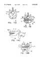
- FIG. 1is a side perspective view of a correction device used in connection with the inventive method for treatment of spinal deformities.
- FIG. 2is a side perspective view of a second type of correction device used in this inventive technique, in which the correction device includes a mechanical wedge member for placement within an opening wedge osteotomy.
- FIG. 3is a top perspective view of a component of the correction device shown in FIG. 2, particularly showing the mechanical wedge member.
- FIG. 4is a top elevational view of the component shown in FIG. 3.
- FIG. 5is an end elevational view of the component shown in FIG. 3.
- FIG. 6is a side elevational view of the component shown in FIG. 3.
- FIG. 7Ais a view of the anterior aspect of a portion of the lumbar spine showing a correction device as depicted in FIG. 2 engaged within a vertebra.
- FIG. 7Bis a view in the coronal plane of the instrumented vertebra in FIG. 7A with the correction device shown in cross-section.
- FIG. 8is a view from the anterior aspect of the spine of a vertebral level with a correction device as depicted in FIG. 1 engaged within the vertebral body.
- FIG. 9is a side elevational view of an alternative embodiment of a connection element for use with the correction devices shown in FIGS. 1 and 2.
- FIG. 10is a top elevational view of the connection element shown in FIG. 9.
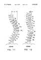
- FIG. 11is a schematic representation of a deformed spine having a King-Type IV scoliotic curve and depicting the locations of opening and closing wedge osteotomies.
- FIG. 12is a view of the spine shown in FIG. 11 with the osteotomies opened and closed in accordance with the inventive technique.
- FIG. 13is a view of the corrected spine shown in FIG. 12 with the inventive instrumentation engaged to the instrumented vertebral levels.
- FIG. 14Ais a view of a vertebra in the coronal plane showing an axis for performing an osteotomy in conjunction with a method of the present invention.
- FIG. 14Bis an anterior to posterior view of the vertebra in FIG. 14A in which the osteotomy site is shown in cross-hatch.
- FIG. 14Cis a lateral view of the vertebra in FIG. 14A in which the osteotomy site is shown in cross-hatch.
- the present inventionconcerns apparatus and methods for use in the correction of spinal deformities without the need for fusion of adjacent vertebrae.
- the inventive techniqueinvolves creating opening and closing osteotomies in the affected vertebrae. Wedges of material are either removed or added to each vertebra as needed to bring the vertebra into a normal spinal alignment.
- the opening/closing osteotomiesare oriented in the vertebral body so as to effect curvature corrections in both the sagittal and the coronal planes.
- the inventive surgical techniquescan be accomplished by novel correction devices for a closing osteotomy.
- One such correction devicecan include upper and lower staples that are engaged on essentially opposite sides of the vertebral body.
- a connection memberspans between the upper and lower staples to apply a slight compressive force to hold the staples in position.
- the connection memberitself can threadedly engage the lower staple and can include an enlarged head to provide a reaction surface as the threaded shank of the connection member passes through an opening in the upper staple.
- the opening osteotomycan be retained by a connection device that includes similar upper and lower staples.
- the opening osteotomy correction deviceincludes a mechanical wedge member attached to the lower staple. The wedge member fits within the osteotomy site to hold the osteotomy open and engage the vertebral body.
- a similar connection memberis provided that can be threaded into the wedge member and that exerts a compressive force at an opening in the upper staple.
- connection membercan include a head portion that is adapted to engage an elongated member spanning the affected vertebrae.
- the connection memberscan be engaged to the elongated member, such as a spinal rod, to stabilize the construct. Once bone union is achieved at the osteotomy sites, the spinal rod can be removed to restore the normal motion of the vertebral segments.
- the correction device 10includes a lower staple 11, an upper staple 12 and a connection member 13.
- the lower staple 11includes a pair of prongs 15 connected to and separated by a base plate 16.
- the prongs 15are configured to be pressed into the hard cortical bone of the vertebral body.
- Such prongstypically include a tapered cross-section to facilitate their insertion and can be of a configuration shown in U.S. Pat. No. 5,395,372, owned by the assignee of the present invention.
- the lower staple 11also includes a threaded boss 17 projecting from the base plate 16 in the same direction of the prongs 15.
- the boss 17is preferably cylindrical and includes an internally threaded bore.
- the upper staple 12 of the correction device 10is similarly formed by upper prongs 20 attached to an upper plate 21.
- the upper staple 12has a greater width between its prongs 20 than the lower staple 11.
- the upper staple 12can have a width of about 2.0 cm between its prongs, while the lower staple 11 can have a width of about 1.5 cm between its prongs 15.
- the dimensions of the upper staple 12 and lower staple 11are principally determined by the anatomy of the particular vertebra into which the staples are engaged.
- the staplesare sized for engagement within a lumbar vertebra.
- both staplescan have essentially the same width between their prongs.
- connection member 13includes an elongated machine threaded shank 25 that bears external threads for mating with the internal threads of the boss 17 of the lower staple 11.
- the machine threaded shank 25has a diameter of 0.30 cm with 5-40 UNC 2A machine threads.
- the internal threads of the boss 17are similarly configured for mating with the threaded shank 25.
- the length of the threaded shank 25is determined by the vertebral anatomy.
- the threaded shank 25has a length sufficient to span substantially across the vertebral body.
- the threaded shank 25For firm engagement of the connection member 13 between the upper and lower staples, it is also preferable that the threaded shank 25 have a length sufficient to extend substantially completely into the threaded boss 17. Likewise, it is also preferable that the threaded boss have a length that is sufficient for a solid threaded engagement between it and the threaded shank. In one embodiment, the threaded boss 17 has a length that is greater than half the length of the threaded shank 25. In a specific embodiment, the threaded shank 25 can have a length of about 45 mm, while the threaded boss 17 of the lower staple 11 has a length of about 25 mm.
- connection member 13In a further aspect of the connection member 13, an enlarged head 26 is provided. A shoulder 27 is situated between the head 26 and the machine threaded shank 25. While the shank 25 is sized to fit through an opening 22 in the upper plate 21 of the upper staple 12, the shoulder 27 has a diameter that is larger than the diameter of the opening 22. In this manner, the connection member 13 can apply a compressive force between the upper and lower staples as the threaded shank 25 is threaded into the boss 17. The shoulder 27 applies a force to the upper staple 12 to push it toward the lower staple 11.
- the head 26 of the connection member 13is configured for engagement to an elongated member extending along the spine adjacent the instrumented vertebrae.
- the head 26can assume a variety of configurations provided that it can be firmly engaged to the elongated member.
- the elongated memberis a spinal rod, such as a spinal rod provided with the TSRH® Spinal System.
- the head 26is generally U-shaped defining a slot 29 between posts 33 forming the U-shape.
- the head 26can also define tool recesses 30 on opposite sides of the posts 33 so that the head can be gripped by a tool useful in threading the shank 25 into the threaded boss 17.
- the head 26further defines an engagement face 31 that is oriented toward the elongated member, or spinal rod.
- the engagement face 31includes a plurality of radial splines 32 emanating from the slot 29.
- the head 26 of the connection member 13is substantially identical to the head of the Variable Angle Bone Screw sold by Danek Medical, Inc. This bone screw is also depicted in U.S. Pat. No. 5,261,909, owned by the Assignee of the present invention. Specific reference is made to FIG. 2 of the '909 Patent and its accompanying description at column 4, lines 10-23, which figure and text are incorporated herein by reference.
- the '909 Patentfurther describes one manner in which the head of the variable angle bone screw is engaged to a spinal rod. Specifically, reference is made to FIGS. 3-5 and the text at column 4, line 35 through column 5, line 47, which description is incorporated herein.
- the head 26 of the connection member 13just like the head of the variable angle bone screw, is engaged to a spinal rod by way of an eyebolt and washer configuration.
- the washerincludes splines that can mate with the splines 32 on the head 26.
- the washeralso engages the spinal rod and permits connection of the head 26 to the spinal rod at variable angular orientations. Again, the details of this type of variable angle connection are now well known as shown in the '909 Patent.
- the correction device 40is used for a closing osteotomy
- the correction device 40depicted in FIG. 2, is provided for use in an opening osteotomy.
- the device 40includes a lower staple 41 and an upper staple 42.
- the lower staple 41includes prongs 45 configured for penetration into the cortical bone of a vertebra.
- a base plate 46connects the prongs 45.
- the upper staple 42includes a pair of prongs 50 connected by an upper plate 51.
- the upper staple 42also defines an opening 52 in the upper plate 51.
- the correction device 40also utilizes the connection member 13 which is, in the specific embodiment, identical to the connection member 13 shown in FIG. 1.
- the connection member 13includes a shoulder 27 that prevents passage of the enlarged head 26 through the opening 52 in the upper plate 51 of the upper staple 42.
- the connection member 13also includes an elongated machine threaded shank 25.
- the connection device 40further includes a wedge member 43 that is configured to be disposed within the osteotomy site to maintain the positioning of the portions of the vertebral body after the osteotomy is opened. Details of the lower staple 41 and the wedge member 43 that is engaged thereto, are shown in FIGS. 3-6.
- the lower staple 41includes a flat edge 47 and a curved edge 48.
- the wedge member 43includes a wedge body 55 that is preferably fixed to the lower staple 41, such as by welding.
- the wedge body 55defines a threaded bore 56 therethrough, that operates substantially similar to the threaded boss 17 of the lower staple 11 of the connection device 10 shown in FIG. 1.
- the threaded bore 56can have a similar thread configuration to the threaded shank 25 of the connection member 13.
- a bore relief 57is provided at the tapered end 61 of the wedge body 55.
- This bore relief 57is preferably formed by angled faces converging toward the threaded bore 56. The relief 57 facilitates entry of the threaded shank 25 of the connection member 13 into the threaded bore 56.
- the wedge body 55further includes a flat end face 58 that is aligned with the flat edge 47 of the lower staple 41.
- a curved face 60On the opposite side of the wedge body 55 from the flat end face 58 is a curved face 60, which also corresponds to the curved edge 48 of the lower staple 41, both features being best shown in FIG. 5.
- the curved face 60preferably conforms substantially to the anterior perimeter of the vertebral body.
- the flat end face 58is provided for clearance from the spinal foramen in the vertebra.
- the wedge member 43can be symmetrically shaped--that is, the wedge body 55 can include a curved end face, such as end face 60, on both sides of the body.
- the wedge body 55it is important that the wedge body 55 provide as large an area as possible for contacting the portions of the vertebral body at the osteotomy site. This contact occurs at the angled side faces 59, which are best shown in FIGS. 3 and 6.
- the angled side faces 59define an angle between each other that specifically corresponds to the amount of opening that is desired at the osteotomy site. In a specific embodiment, the angle between the angled side faces 59 is 15 degrees.
- the wedge body 55has a height of about 1.25 cm from the bore relief 57 to the lower staple 41.
- the lower staple 41can have a relief bore 49 aligned with the threaded bore 56 of the wedge body 55.
- the connection member 13can have a length sufficient to partially extend into the relief bore 49 of the lower staple 41.
- the edge of the angled faces, and more specifically the curved end face 60is formed at a radius of 0.95 cm.
- FIGS. 7A, 7B and 8One specific manner of placement of the correction devices 10 and 40 is shown in FIGS. 7A, 7B and 8. Looking first at FIG. 8, the correction device 10 is shown positioned in the anterior portion of the vertebral body.
- the connection member 13spans essentially laterally across the vertebral body, with the lower staple 11 and upper staple 12 penetrating the cortical bone of the vertebral body.
- the staplesPreferably, the staples have a width sufficiently narrow to keep them out of the adjacent discs D and fully contained within the vertebral body V.
- the head 26is oriented with its posts 33 aligned substantially within the coronal plane. In this manner, connection of the head 26 of the member 13 to a spinal rod by way of an eyebolt occurs with the spinal rod extending along the length of the spine.
- FIGS. 7A and 7Bthe correction device 40 is depicted engaged within a vertebral body V. Again, the correction device 40 extends transversely across the anterior portion of the vertebral body with the lower staple 41 and upper staple 42 penetrating the cortical bone.
- FIG. 7Billustrates the orientation of the wedge member 43 within the osteotomy site. It can be seen from this Figure that the curved face 60 approximates the anterior edge of the vertebral body V. The flat end face 58 then provides clearance for the vertebral foramen F so that the wedge member does not impinge upon the spinal cord within the foramen.
- connection devices 10 and 40are preferably formed of a biocompatible sterilizable medical grade material.
- the components of the correction devices 10 and 40can be formed of stainless steel, while in other applications titanium can be the material of choice.
- the wedge member 43can be a solid member.
- the wedge member 43can be formed of a porous material, such as certain porous ceramics or a porous tantalum, such as HEDROCEL® produced by Implex Corporation.
- the wedge member 43can include hollow portions with openings in the angled side faces 59 in contact with the vertebral body.
- One object of these specific embodiments of the wedge member 43is to permit tissue growth across and through the wedge member 43.
- One goal of the procedure of the present inventionis to achieve bone union of the portions of the vertebral body at the osteotomy sites. In the case where the osteotomy is closed, bony material is in direct contact so that bone union can occur fairly easily and rapidly.
- introduction of the wedge member 43 into an open osteotomy sitecan delay this bone union.
- Providing a wedge member 43 that allows for tissue growth through and/or into the wedge membercan enhance the likelihood and rate of bone union of an open osteotomy site.
- the wedge member 43is preferably formed of the porous tantalum HEDROCEL® material which not only permits bone growth through the wedge member 43, but also allows the member to be fully integrated into the resulting bone union.
- connection member 13 for the correction devices 10 and 40can be replaced by a connection member 65 as depicted in FIGS. 9 and 10.
- the connection member 65includes a threaded shank 66 that can be identical to the threaded shank 25 of the connection member 13.
- the primary difference between connection member 65 and the prior memberis that the head 67 of member 65 is configured to directly receive a spinal rod therein.
- the head 67includes a pair of opposite arms 68 which form a U-shaped rod channel 69 therebetween.
- the rod channel 69has a width and diameter that is just slightly larger than the diameter of a spinal rod so that the rod can be seated within the channel.
- the arms 68further define an internally threaded bore 70 that intersects the rod channel 69.
- a threaded plug(not shown) can be used to clamp the rod within the rod channel by threading into the threaded bore 70.
- the head 67 of the connection member 65 of the present embodimentcan be similar to the head of certain bone screws provided with the CD® and CCD® Spinal Systems sold by Sofamor, S.N.C., a subsidiary of Sofamor Danek Group. Some details of the construct can also be found in U.S. Pat. No. 5,147,360, assigned to Sofamor, S.N.C. Particularly, FIG. 5 of the '360 Patent, together with the specification at column 4, lines 44-55, which disclosure is incorporated herein by reference, show one embodiment of a head of a bone screw for use with the present invention.
- connection member 65is preferred since it permits toploading introduction of the rod into the head of the member when the correction devices 10, 40 are implanted within the patient.
- different head configurations for the connection memberscan be provided depending upon the type of elongated member extending along the length of the spine and the type of connection desired.
- the elongated member extending along the length of the spineis a plate
- the head, such as head 26 of connection member 13can be in the form of a machine threaded post. This machine threaded post could then be engaged through a slot in the elongated plate by way of a nut.
- Such a connectionis accomplished in the DYNALOK® bone bolt and plate sold by Danek Medical, Inc.
- connection membercan be closed, meaning that the elongated member spanning the length of the spine must be threaded through an opening defined in the head of the connection member.
- the elongated membershould be capable of removal once bone union occurs at the osteotomy sites.
- FIG. 11a portion of a patient's spine from T 3 to the sacrum is shown in which the spine has a King-Type IV scoliotic curve.
- the apex of the curveis offset a distance D from its correct alignment in the coronal plane.
- the spineis deformed laterally so that the axes of the vertebral bodies are displaced from the sagittal plane passing through the spine of the patient.
- the spinal deformity depicted in FIG. 11is but one of many types of spinal deformities that can be addressed by the devices and techniques of the present invention.
- wedge osteotomies R 6 -R 11can be cut from the thoracic vertebra T 6 -T 11 at the convex side of the curvature.
- a 15 degree osteotomy wedge of bone from the vertebral bodyis removed, although other wedge dimensions can be accommodated depending upon the amount of curvature and lateral offset of the particular vertebra.
- opening osteotomies X 1 -X 4can be cut into the vertebra L 1 -L 4 .
- no bone materialis removed. Instead, the vertebral body is essentially fractured to permit an opening osteotomy at that vertebral level.
- the cut into the lumbar vertebraeoccurs on the same side of the spine as the wedge osteotomies in the thoracic vertebrae.
- the various osteotomies in the thoracic and lumbar vertebraecan be performed using conventional tools and instruments, such as a chisel and an osteotomy spreader.
- the spinecan be manipulated to close the closing osteotomies R 6 -R 11 and open the lumbar osteotomies X 1 -X 4 .
- the spinewould then appear as shown in FIG. 12 in which the thoracic osteotomies are closed at sites C 6 -C 11 and the lumbar osteotomy sites are left open at sites W 1 -W 4 .
- the lateral offset of scoliotic curvatureis reduced to an offset D' that is significantly less than the original curvature deformity.
- the offset D'would be negligible so that the spine would appear properly aligned in the coronal plane.
- each closing osteotomywill eliminate a certain amount of the abnormal curvature as the osteotomy is closed as shown in FIG. 12.
- each opening osteotomy in the lumbar spinewill cause an effective translation of the particular lumbar vertebra toward the spinal midline.
- the amount of effective shifting of the axis of a lumbar vertebra toward the spinal midlinecan be based upon the size of the opening wedge osteotomy performed at that vertebra. It is, however, preferable that the opening or closing wedge osteotomies not exceed a 15 degree segment removed from or added to the vertebral body, in order to preserve the vertebral architecture as much as possible and to reduce the possibility of narrowing of the disc space.
- the correction devices 10 and 40can be engaged to the respective vertebrae.
- the correction device 10is engaged to the thoracic vertebrae, with the lower staples 11 positioned on one side of the vertebral body, and upper staples 12 positioned on the contra-lateral side of the vertebral body.
- the connection memberwhich can be member 65 in FIG. 13, is then engaged between the upper and lower staples.
- a borecan be formed laterally through the vertebral body essentially through the centerline of the osteotomy. In certain techniques, the centerline of the osteotomy will extend laterally through the vertebral body and generally intersecting the center of the body.
- the borecan be prepared using a conventional drill or even using a curette.
- a similar procedureis performed to introduce the correction device 40 to the lumbar vertebrae.
- the wedge members 43are disposed within the open osteotomy sites W 1 -W 4 .
- the lower and upper staples 41, 42, respectively,are then engaged to the vertebral bodies.
- the staples of both correction devices 10 and 40are used to press the halves of the vertebral body together to close the osteotomy site as in the thoracic vertebrae, or to press the vertebral halves against the wedge member 43.
- bone fusion material or bone cementcan be introduced into the osteotomy site to facilitate complete closure and ultimate bone union.
- the elongated membersuch as spinal rod 72
- the spinal rod 72can be engaged to each of the connection members 65 in the manner described above.
- the spinal rod 72may be pre-bent to a particular curvature. In the configuration shown in FIG. 13, a certain amount of lateral curvature remains so that the rod would be pre-bent to emulate that lateral curvature. Further straightening of the spine can be accomplished if the rod 72 does not completely emulate the intermediate corrected curvature. In that instance, some widening and narrowing of the intervertebral disc space may occur, but it may be expected that the disc space height would be restored once the spinal rod 72 is removed.
- the spinal rod 72is preferably bent to correspond to the normal kyphotic and lordotic curvatures of the thoracic and lumbar spine segments. In this manner, the flat back syndrome can be avoided. Care must be taken that the sagittal plane curvature of the spinal rod 72 not exceed the physiologic capability of the spinal segments. In other words, the deformed spine of a patient may also have a curvature deformity in the sagittal as well as the coronal planes. Under some circumstances, the rod rolling technique frequently utilized with the CD® Spinal System can also be implemented where an intermediate corrected residual curvature remains.
- pre-bending the rod 72 to conform to that residual curvature, such as shown in FIG. 13,can also approximate the normal kyphotic and lordotic curvatures for a healthy spine.
- the rod 72 shown in FIG. 13can be rolled about its axis so that the spine becomes perfectly aligned in the coronal plane with the restoration of the normal curvature in the sagittal plane.
- the correction devices 10 and 40 and the spinal rod 72are implanted from an anterior approach.
- only a single rodis required to maintain the stability of the correction. Since the physiology of the discs and vertebrae are not being changed, the elastic strength of the intervertebral discs will help retain the spinal column in its corrected configuration. Since each of the vertebral bodies is held together by way of staples on opposite sides of the body, there is substantially no risk that the osteotomy sites will separate or fail.
- the present inventiontakes advantage of the natural strength of the spine in order to retain the stability of the temporary fixation at least until bone union occurs. Depending upon the overall health of the patient and of the vertebral bodies, this bone union can occur in a manner of a few months.
- the spinal rod 72is no longer essential to maintain the stability of the spine.
- the rod 72can be removed by disconnecting it from each of the connection members 13 or 65, leaving only the head of the connection member projecting beyond the vertebral body.
- the intervertebral discsresume their normal function and the patient's spinal column is as close to a normal configuration as possible.
- a biodegradable or resorbable rodcan also be contemplated. In this instance, the rod would gradually resorb.
- the correction devices 10 and 40also become superfluous once bone union is achieved at the osteotomy site.
- the components of the correction devicescan also be resorbable.
- One example previously discussedis the formation of the wedge member 43 out of a porous tantalum or HEDROCEL® material.
- a similar materialmay be usable to form the staples and the connection members, provided that the material forming these components can still meet their strength requirements.
- the spinal rod or elongated membermay not be necessary to stabilize the instrumentation.
- the elongated spinal member or rodmay not be required. Since the present invention contemplates correction of spinal deformities without fusion, additional fixation devices are not as essential as in other procedures in which fusion occurs. In those other procedures, the spinal segments must be essentially immobilized in order for the bony bridge to be formed across the intervertebral disc space. These same requirements are absent in the present inventive technique using the novel devices described above.
- connection members 13, 65provide a compressive force between the upper and lower staples to hold them within the vertebral body. It is understood, that this compressive force is not so great as to cause subsidence of the staples within the vertebral body.
- the connection member 13, 65does not require the presence of a head 26, 67 which would ordinarily be engaged to the spinal rod.
- connection membercan be modified to simply include an enlarged shoulder 27 with a driving tool recess formed in the shoulder to receive a driving tool for threading the threaded shank 25, 66 of the connection member into the threaded boss 17 or the threaded bore 56.
- the vertebraewill be held in their corrected position by the elasticity of the intervertebral discs. Since the geometry of the vertebral bodies has been altered, the spine should automatically assume its corrected position, even without the assistance of an additional member spanning the spine.
- the present inventionalso contemplates a surgical technique in which curvature deformities in multiple planes can be corrected. For instance, in many cases, the patient's spine suffers not only from scoliosis, but also from some degree of kyphosis or lordosis. In this instance, correction of an abnormal curvature must occur in two planes. The present invention readily permits such a correction.
- the vertebral body Vhas an axis Z from the center of the vertebral body directed posteriorly and an axis Y directed laterally within the coronal plane.
- the centerline of the osteotomy 75can be oriented at an angle a relative to the axis Y.
- the centerline 75 of the osteotomycorresponds or is aligned with the axis Y.
- FIGS. 14B and 14Cremoval of bone material for a closing osteotomy R, or addition of a wedge member for an opening osteotomy W is depicted. The angular orientation of the osteotomy at the angle ⁇ achieves correction and re-alignment of the vertebra in two planes.
- the present inventionprovides a surgical technique that permits correction of spinal deformities without the need for fusion of the intervertebral discs.
- the osteotomies conducted according to the techniquecan be done rapidly using conventional instruments while still protecting the spinal cord and controlling bleeding.
- the use of staples on opposite sides of the vertebral bodymaintain the osteotomy sites in their required configuration for bone union to occur.
- Ancillary support for the instrumented vertebraecan be provided by way of a removable elongated member spanning the spine, such as a spinal rod.
- the spinal rodneed not bear as much of the spinal loads as in the other procedures.
- the rodcan have a smaller diameter than traditional spinal instrumentation rods.
- An ultimate goal of the present inventionis removal of the spinal rod once bone union has occurred at the osteotomy site.
- the present inventioncontemplates application to a wide variety of spinal deformities, although correction of scoliosis may be a principal application.
Landscapes
- Health & Medical Sciences (AREA)
- Orthopedic Medicine & Surgery (AREA)
- Surgery (AREA)
- Life Sciences & Earth Sciences (AREA)
- Heart & Thoracic Surgery (AREA)
- Nuclear Medicine, Radiotherapy & Molecular Imaging (AREA)
- Engineering & Computer Science (AREA)
- Biomedical Technology (AREA)
- Neurology (AREA)
- Medical Informatics (AREA)
- Molecular Biology (AREA)
- Animal Behavior & Ethology (AREA)
- General Health & Medical Sciences (AREA)
- Public Health (AREA)
- Veterinary Medicine (AREA)
- Surgical Instruments (AREA)
- Prostheses (AREA)
Abstract
Description
The present invention concerns instrumentation and techniques for the treatment of spinal deformities. In particular, the inventive methods and devices accomplish this treatment without the need for fusion of the spine.
Surgical intervention for the treatment of injuries to, and deformities of the spine is approaching its first century. Nevertheless, the field of spinal surgery was not significantly advanced until the development of the hook and rod system by Dr. Harrington in the early 1950's. Dr. Harrington developed this system in Houston when he began care of children with progressive neuromuscular scoliosis secondary to polio. Until that time, the progressive scoliosis had been treated with external casts, which themselves yielded unacceptably high complication rates. After a decade of development, the hook and rod system evolved into the form that is known today as the Harrington Instrumentation.
The original primary indication for use of Harrington Instrumentation was in the treatment of scoliosis. Scoliosis is a deformity of the spine in the coronal plane, in the form of an abnormal curvature. While a normal spine presents essentially a straight line in the coronal plane, a scoliotic spine can present various lateral curvatures in the coronal plane. The types of scoliotic deformities have been graded as King-Type I through V curves depending upon the nature and severity of the abnormality. In some instances, the scoliosis is manifested by a single abnormal curve, typically in the thoracic spine. In other instances, the abnormality can constitute a double curve in both the thoracic and lumbar regions.
Early techniques for correction of scoliosis utilized a halo-traction device. In this technique, a halo is fixed to the skull and a vertical force is applied to the spine through the skull. In a halo-femoral traction approach, the patient is supine and traction forces are applied through a halo and a femoral pin. In a halo-gravity traction procedure, the patient sits in a wheelchair and a suspended weight applies a vertical force through the halo. In halo-pelvic traction, a pelvic ring is affixed to the patient and a series of threaded rods connect the cranial halo to the pelvic ring to apply an adjustable force separating the two rings. In procedures using the halo, the patient is either immobile or severely restricted in mobility.
To avoid the need for halos, various rod-based systems have been developed. Of course, the original rod system for correction of scoliosis is the Harrington System which utilized threaded and notched rods. In particular, a typical Harrington System utilizes a notched distraction rod and at least one threaded compression rod, with the distraction and compression rods being applied to the concave and convex portions of the curvature, respectively. In some procedures, a single distraction rod spans across several thoracic and lumbar vertebrae, such as between T5 and L4 to correct a King-Type I curve. The threaded compression rods are then used to stabilize the rod fixation. In other approaches, the compression rod spans across the convex portion of the curve, such as between T6 and L2 in the correction of a King-Type IV curve. In a Harrington procedure, a hook placed at the notched end of the distraction rod can be progressively advanced toward the cranial end of the rod to progressively correct the spinal deformation. At the same time, hooks engaged to the threaded compression rods can be drawn together on the convex side of the curvature to assist in the correction and to stabilize the instrumented spine.
In an additional step of the Harrington procedure, once the spine has been substantially corrected, transverse stabilization can be added between the two rods extending on opposite sides of the spine. Moreover, for long term stability, bone graft is placed along the instrumented vertebral levels to promote fusion along that portion of the spine.
One drawback commonly associated with the Harrington System is that the rods are completely straight. As a result, patients in which a Harrington System has been used to correct a scoliosis condition have been left with the so-called flat-back syndrome. Specifically, in correcting the lateral curvature of the spine, the normal sagittal plane curvature is eliminated by the presence of a completely straight rod. In some cases, it has been found that the patient is better off retaining the scoliotic curvature than enduring the complications associated with flat-back syndrome.
To address this syndrome, subsequent rod-based systems have relied upon pre-bent spinal rods. Specifically, the rods are bent to the normal thoracic kyphosis and lumbar lordosis in the sagittal plane. One such system is the Luque segmental spinal instrumentation. In the early 1980's, Dr. Luque pioneered a technique for segmental correction of abnormal spinal curvatures in which wires were used to affix vertebral levels to a pre-bent rod. These sublaminar wires are used to help draw the vertebrae toward the rod and ultimately to hold the vertebrae in position. In one approach using Luque instrumentation, a unit rod is provided which utilizes a single rod anchored at its ends to the ilium and bent at its cranial end so that two halves of the rod are oriented on opposite sides of the spinal column. The unit rod can then be used as a lever to straighten the spine, after which Luque sublaminar wires are used to fix the vertebrae to the unit rod.
As with the Harrington System, the final step of the Luque Instrumentation is frequently fusion of the instrumented spinal segments. There have been suggestions for instrumentation without fusion to correct scoliosis in younger patients, this technique was believed to permit further spinal growth. However, the results of this instrumentation without fusion were not very promising and led to certain complications, including loss of correction, reduced spinal growth and an unacceptable rate of instrumentation failure.
In yet another rod-based instrumentation system pioneered by Dr. Cotrel in France, a pre-curved rod is engaged to the vertebrae at the concave side of the abnormal curvature. The rod is then rolled about its axis to derotate the scoliotic curvature and at the same time provide the instrumented segments with the normal sagittal plane curvature. For instance, in the correction of thoracic lordoscoliosis, rolling of a pre-curved rod not only derotates the curvature in the coronal plane, it also transforms that scoliotic curvature into a physiological thoracic kyphosis. The rod is held to the vertebrae by a series of hooks, which are ultimately fixed to the rod once the derotation process is complete. To ensure a stable correction, an additional rod is added on the opposite side of the spinous process from the first rod. Members for transversely connecting the two rods create a rigid scaffold are attached. Again, in this procedure, bone chips are placed along the instrumented vertebrae to achieve fusion at the instrumentation site.
Other rod-based systems have been developed over the last several years that accomplish similar correction of spinal deformities, such as scoliosis. For example, the TSRH® Universal Spine System of Danek Medical, Inc. and the ISOLA® Spine System of AcroMed Corp. can be instrumented to the spine to correct various types of spinal deformities. In all of these rod-based systems, the spinal rods are permanently fixed to the patient's spine. Of course, once fusion of all the instrumented levels has occurred, the original instrumentation is largely superfluous.
Other techniques that have been developed for correction of spinal deformities involve the use of spinal osteotomies. In one such approach, osteotomies of displaced vertebrae are performed anteriorly from the convex side of the abnormal curvature. In this technique, the intervertebral discs are removed and an osteotomy spreader is used to separate the adjacent vertebrae, thereby realigning the vertebral bodies in the coronal plane. Fusion material, such as bone chips, are inserted into the widened intervertebral disc spaces to ultimately achieve fusion at those vertebral levels. While immobilization using an external cast or brace can be utilized while fusion is occurring, typically internal instrumentation, such as rigid plates, are affixed to the vertebral bodies along the segments to be fused.
A related technique involves Dwyer instrumentation that utilizes a flexible cable. In this technique, the cable is connected to the affected vertebrae on the convex side of the curvature. The cable is then shortened, thereby applying compression to the convex side of the curvature. Once the curvature has been corrected using the Dwyer cable, ancillary instrumentation, such as a Harrington rod, can be added for fixing and stabilizing the spine. In the Dwyer instrumentation, Dwyer clamps are pressed into the vertebral bodies to provide a seat for the insertion of Dwyer screws. The Dwyer screws define a channel through which the Dwyer cable can pass to perform the compression and ultimately the derotation of the abnormal curvature.
A similar approach is taken using Zielke instrumentation, except that the Dwyer cable is replaced by a pre-bent threaded rod. Application of the compressive forces to reduce the convex side of the curvature occurs by threaded nuts along the rod to translate the bone screws engaged to the vertebrae. Dr. Kostuik has suggested a modification of the Dwyer and Zielke approaches. In this approach, posterior osteotomies are closed and anterior wedges opened using similar compression and extraction devices. Again, as with the Harrington technique, the open wedge osteotomies are filled with fusion material and typically the intervertebral disc spaces are resected and the spaces also filled with bone chips to achieve fusion.
While many techniques and instrumentation have been developed for the correction of spinal deformities, none have been devised that can achieve the necessary correction without either fusion of the instrumented vertebral levels or permanent retention of hardware within the patient. Moreover, some of the techniques result in an undesirable flat-back syndrome in which the normal sagittal plane curvature is eliminated. In addition, most of the prior systems greatly restrict the patient's normal mobility, and some restrict the growth of the spine. In the latter instance, some of the spinal instrumentation is not acceptable for use in younger patients.
A need exists for a technique and system to correct spinal deformities without the necessity of fusing the corrected vertebral segments. A need also exists for a system and technique that can accomplish this correction with minimal long-term invasion of the patient.
In order to address these unmet needs, a method and instrumentation are provided for correction of spinal deformities without the need for fusion of the corrected segments. In one aspect of the invention, a surgical technique is provided in which osteotomies are closed on the convex side of the curvature deformity and opened on the concave side of the curvature. Mechanical wedges are engaged within the open wedge osteotomies on the concavity of the curvature. The vertebral bodies will heal and form a unified body at the location of the closed osteotomies. In this manner, the normal coronal plane position of the spine is restored by elimination of the curvature deformity.
In a further aspect of the technique, the orientation of the opening or closing wedge osteotomies can be predetermined to achieve a normal curvature in the sagittal plane and normal spinal orientation in the coronal plane. For example, the addition of mechanical wedges into opening wedge osteotomies in the lumbar spine can be used to eliminate an abnormal lateral curvature while restoring the normal lordotic curvature of the lumbar vertebrae.
In a further aspect of the technique, connection elements or fasteners are engaged to each of the vertebrae in which an osteotomy has been performed. The connection element can then be engaged to an elongated member, such as a spinal rod, that has been pre-bent to the adjusted spinal curvature. The longitudinal member stabilizes the spine as the closing osteotomies heal and the mechanical wedges become integrated into the vertebrae having the opening wedge osteotomies. In this manner, the intervertebral discs are maintained intact. Moreover, and perhaps most significantly, none of the vertebral levels are fused together. Once the vertebral bodies have completely healed, the longitudinal member can be removed. With this feature of the inventive technique, the normal mobility of the patient's spine is restored since the intervertebral discs are not fused.
In another aspect of the invention, instrumentation is provided that can be used to perform the inventive technique. In one feature of the invention, the instrumentation includes a correction device that includes an upper and lower staple. Tithe staples are configured to penetrate the vertebral body at substantially opposite sides of the body. A connection element is provided that extends between the upper and lower staples and through the vertebral body. In one feature, the connection element includes a threaded shank that engages a similarly threaded boss on the lower staple. In this manner, the connection element can be used to provide a compressive force between the upper and lower staples, thereby retaining their position and engagement with the vertebral body.
In a further aspect of the inventive instrumentation, the connection element includes a head portion adjacent the upper staple. The head portion can be configured for connection to an elongated member used to stabilize the spine. In one embodiment, the head of the connection element is configured to engage an elongated spine rod.
In accordance with a further feature of the invention, two types of correction devices can be provided. One correction device is utilized to close the closing wedge osteotomy in a vertebral body. In this correction device, the connection element is used to engage an upper and lower staple to the vertebral body. In the second correction device, a mechanical wedge is attached to the lower staple. The second correction device is thus used in maintaining the opened wedge osteotomies on the concavity of the curvature. The mechanical wedge member is situated within the open space created by the opening wedge osteotomy. The staples, and particularly the lower staple. stabilize the opening wedge osteotomy closed around the mechanical wedge as the vertebral body heals.
In accordance with the present invention, a method is provided for correcting spinal deformities without the need for fusion of the spine. A further object of the invention is accomplished by the technique and instrumentation that allows a stabilizing elongated member to be used only temporarily. This aspect provides the benefit that the elongated member, such as the spinal rod, can be removed once the instrumented vertebrae have healed, thereby restoring the normal mobility to the patient's spine.
Another object of the present invention is achieved by aspects of the technique and instrumentation that allow for adjustment of the spinal curvature in both the sagittal and the coronal planes. Still other objects and certain benefits of the invention will be discerned from the following written description of the invention together with the accompanying figures.
FIG. 1 is a side perspective view of a correction device used in connection with the inventive method for treatment of spinal deformities.
FIG. 2 is a side perspective view of a second type of correction device used in this inventive technique, in which the correction device includes a mechanical wedge member for placement within an opening wedge osteotomy.
FIG. 3 is a top perspective view of a component of the correction device shown in FIG. 2, particularly showing the mechanical wedge member.
FIG. 4 is a top elevational view of the component shown in FIG. 3.
FIG. 5 is an end elevational view of the component shown in FIG. 3.
FIG. 6 is a side elevational view of the component shown in FIG. 3.
FIG. 7A is a view of the anterior aspect of a portion of the lumbar spine showing a correction device as depicted in FIG. 2 engaged within a vertebra.
FIG. 7B is a view in the coronal plane of the instrumented vertebra in FIG. 7A with the correction device shown in cross-section.
FIG. 8 is a view from the anterior aspect of the spine of a vertebral level with a correction device as depicted in FIG. 1 engaged within the vertebral body.
FIG. 9 is a side elevational view of an alternative embodiment of a connection element for use with the correction devices shown in FIGS. 1 and 2.
FIG. 10 is a top elevational view of the connection element shown in FIG. 9.
FIG. 11 is a schematic representation of a deformed spine having a King-Type IV scoliotic curve and depicting the locations of opening and closing wedge osteotomies.
FIG. 12 is a view of the spine shown in FIG. 11 with the osteotomies opened and closed in accordance with the inventive technique.
FIG. 13 is a view of the corrected spine shown in FIG. 12 with the inventive instrumentation engaged to the instrumented vertebral levels.
FIG. 14A is a view of a vertebra in the coronal plane showing an axis for performing an osteotomy in conjunction with a method of the present invention.
FIG. 14B is an anterior to posterior view of the vertebra in FIG. 14A in which the osteotomy site is shown in cross-hatch.
FIG. 14C is a lateral view of the vertebra in FIG. 14A in which the osteotomy site is shown in cross-hatch.
For the purpose of promoting an understanding of the principles of the invention, reference will now be made to preferred embodiments thereof and specific language will be used to describe the same. It will nevertheless be understood that no limitation of the scope of the invention is thereby intended, such alterations and further modifications in the invention, and such further applications of the principles of the invention as described therein being contemplated as would normally occur to one skilled in the art to which the invention relates.
The present invention concerns apparatus and methods for use in the correction of spinal deformities without the need for fusion of adjacent vertebrae. In general terms, the inventive technique involves creating opening and closing osteotomies in the affected vertebrae. Wedges of material are either removed or added to each vertebra as needed to bring the vertebra into a normal spinal alignment. In another aspect of the technique, the opening/closing osteotomies are oriented in the vertebral body so as to effect curvature corrections in both the sagittal and the coronal planes.
The inventive surgical techniques can be accomplished by novel correction devices for a closing osteotomy. One such correction device can include upper and lower staples that are engaged on essentially opposite sides of the vertebral body. A connection member spans between the upper and lower staples to apply a slight compressive force to hold the staples in position. The connection member itself can threadedly engage the lower staple and can include an enlarged head to provide a reaction surface as the threaded shank of the connection member passes through an opening in the upper staple.
The opening osteotomy can be retained by a connection device that includes similar upper and lower staples. In one modification, the opening osteotomy correction device includes a mechanical wedge member attached to the lower staple. The wedge member fits within the osteotomy site to hold the osteotomy open and engage the vertebral body. A similar connection member is provided that can be threaded into the wedge member and that exerts a compressive force at an opening in the upper staple.
In both correction devices, the connection member can include a head portion that is adapted to engage an elongated member spanning the affected vertebrae. In one aspect of the invention, once the opening and closing osteotomies have been perfected by way of the correction devices, the connection members can be engaged to the elongated member, such as a spinal rod, to stabilize the construct. Once bone union is achieved at the osteotomy sites, the spinal rod can be removed to restore the normal motion of the vertebral segments.
With this general description in mind, specific details of the correction devices can be seen with reference to FIGS. 1-10. Looking first at FIG. 1, acorrection device 10 is depicted that is used for the closing osteotomy discussed above. Thecorrection device 10 includes alower staple 11, anupper staple 12 and aconnection member 13. Thelower staple 11 includes a pair ofprongs 15 connected to and separated by abase plate 16. Theprongs 15 are configured to be pressed into the hard cortical bone of the vertebral body. Such prongs typically include a tapered cross-section to facilitate their insertion and can be of a configuration shown in U.S. Pat. No. 5,395,372, owned by the assignee of the present invention. Thelower staple 11 also includes a threadedboss 17 projecting from thebase plate 16 in the same direction of theprongs 15. Theboss 17 is preferably cylindrical and includes an internally threaded bore.
Theupper staple 12 of thecorrection device 10 is similarly formed byupper prongs 20 attached to anupper plate 21. In accordance with the preferred embodiment, theupper staple 12 has a greater width between itsprongs 20 than thelower staple 11. In one specific embodiment, theupper staple 12 can have a width of about 2.0 cm between its prongs, while thelower staple 11 can have a width of about 1.5 cm between itsprongs 15. Of course, it is understood that the dimensions of theupper staple 12 andlower staple 11 are principally determined by the anatomy of the particular vertebra into which the staples are engaged. In the specific example above, the staples are sized for engagement within a lumbar vertebra. It is further understood that while in the preferred embodiment the upper staple is wider than the lower staple, both staples can have essentially the same width between their prongs.
The next element of thecorrection device 10 is theconnection member 13. Theconnection member 13 includes an elongated machine threadedshank 25 that bears external threads for mating with the internal threads of theboss 17 of thelower staple 11. In one specific embodiment, the machine threadedshank 25 has a diameter of 0.30 cm with 5-40 UNC 2A machine threads. The internal threads of theboss 17 are similarly configured for mating with the threadedshank 25. The length of the threadedshank 25 is determined by the vertebral anatomy. Preferably, the threadedshank 25 has a length sufficient to span substantially across the vertebral body. For firm engagement of theconnection member 13 between the upper and lower staples, it is also preferable that the threadedshank 25 have a length sufficient to extend substantially completely into the threadedboss 17. Likewise, it is also preferable that the threaded boss have a length that is sufficient for a solid threaded engagement between it and the threaded shank. In one embodiment, the threadedboss 17 has a length that is greater than half the length of the threadedshank 25. In a specific embodiment, the threadedshank 25 can have a length of about 45 mm, while the threadedboss 17 of thelower staple 11 has a length of about 25 mm.
In a further aspect of theconnection member 13, anenlarged head 26 is provided. Ashoulder 27 is situated between thehead 26 and the machine threadedshank 25. While theshank 25 is sized to fit through anopening 22 in theupper plate 21 of theupper staple 12, theshoulder 27 has a diameter that is larger than the diameter of theopening 22. In this manner, theconnection member 13 can apply a compressive force between the upper and lower staples as the threadedshank 25 is threaded into theboss 17. Theshoulder 27 applies a force to theupper staple 12 to push it toward thelower staple 11.
In a further aspect of the invention, thehead 26 of theconnection member 13 is configured for engagement to an elongated member extending along the spine adjacent the instrumented vertebrae. In accordance with the invention, thehead 26 can assume a variety of configurations provided that it can be firmly engaged to the elongated member. In the preferred embodiment, the elongated member is a spinal rod, such as a spinal rod provided with the TSRH® Spinal System. In the specific embodiment illustrated in FIG. 1, thehead 26 is generally U-shaped defining aslot 29 betweenposts 33 forming the U-shape. Thehead 26 can also define tool recesses 30 on opposite sides of theposts 33 so that the head can be gripped by a tool useful in threading theshank 25 into the threadedboss 17.
Thehead 26 further defines anengagement face 31 that is oriented toward the elongated member, or spinal rod. In a specific embodiment, theengagement face 31 includes a plurality ofradial splines 32 emanating from theslot 29. In this illustrated embodiment, thehead 26 of theconnection member 13 is substantially identical to the head of the Variable Angle Bone Screw sold by Danek Medical, Inc. This bone screw is also depicted in U.S. Pat. No. 5,261,909, owned by the Assignee of the present invention. Specific reference is made to FIG. 2 of the '909 Patent and its accompanying description at column 4, lines 10-23, which figure and text are incorporated herein by reference. The '909 Patent further describes one manner in which the head of the variable angle bone screw is engaged to a spinal rod. Specifically, reference is made to FIGS. 3-5 and the text at column 4, line 35 throughcolumn 5,line 47, which description is incorporated herein. To summarize, thehead 26 of theconnection member 13, just like the head of the variable angle bone screw, is engaged to a spinal rod by way of an eyebolt and washer configuration. The washer includes splines that can mate with thesplines 32 on thehead 26. The washer also engages the spinal rod and permits connection of thehead 26 to the spinal rod at variable angular orientations. Again, the details of this type of variable angle connection are now well known as shown in the '909 Patent.
While thecorrection device 10 is used for a closing osteotomy, thecorrection device 40, depicted in FIG. 2, is provided for use in an opening osteotomy. Like thecorrection device 10, thedevice 40 includes alower staple 41 and anupper staple 42. Thelower staple 41 includesprongs 45 configured for penetration into the cortical bone of a vertebra. Abase plate 46 connects theprongs 45. Likewise, theupper staple 42 includes a pair ofprongs 50 connected by anupper plate 51. Like theupper staple 12, theupper staple 42 also defines anopening 52 in theupper plate 51. Thecorrection device 40 also utilizes theconnection member 13 which is, in the specific embodiment, identical to theconnection member 13 shown in FIG. 1. In that regard, theconnection member 13 includes ashoulder 27 that prevents passage of theenlarged head 26 through theopening 52 in theupper plate 51 of theupper staple 42. Theconnection member 13 also includes an elongated machine threadedshank 25.
Theconnection device 40 further includes awedge member 43 that is configured to be disposed within the osteotomy site to maintain the positioning of the portions of the vertebral body after the osteotomy is opened. Details of thelower staple 41 and thewedge member 43 that is engaged thereto, are shown in FIGS. 3-6. In one specific embodiment, thelower staple 41 includes aflat edge 47 and acurved edge 48. Thewedge member 43 includes awedge body 55 that is preferably fixed to thelower staple 41, such as by welding. Thewedge body 55 defines a threadedbore 56 therethrough, that operates substantially similar to the threadedboss 17 of thelower staple 11 of theconnection device 10 shown in FIG. 1. In particular, the threaded bore 56 can have a similar thread configuration to the threadedshank 25 of theconnection member 13. Abore relief 57 is provided at thetapered end 61 of thewedge body 55. This borerelief 57 is preferably formed by angled faces converging toward the threaded bore 56. Therelief 57 facilitates entry of the threadedshank 25 of theconnection member 13 into the threaded bore 56.
Thewedge body 55 further includes aflat end face 58 that is aligned with theflat edge 47 of thelower staple 41. On the opposite side of thewedge body 55 from theflat end face 58 is acurved face 60, which also corresponds to thecurved edge 48 of thelower staple 41, both features being best shown in FIG. 5. Thecurved face 60 preferably conforms substantially to the anterior perimeter of the vertebral body. Theflat end face 58 is provided for clearance from the spinal foramen in the vertebra. It is understood, that in some specific embodiments, thewedge member 43 can be symmetrically shaped--that is, thewedge body 55 can include a curved end face, such asend face 60, on both sides of the body.
In accordance with certain aspects of the invention, it is important that thewedge body 55 provide as large an area as possible for contacting the portions of the vertebral body at the osteotomy site. This contact occurs at the angled side faces 59, which are best shown in FIGS. 3 and 6. The angled side faces 59 define an angle between each other that specifically corresponds to the amount of opening that is desired at the osteotomy site. In a specific embodiment, the angle between the angled side faces 59 is 15 degrees. In one specific embodiment, thewedge body 55 has a height of about 1.25 cm from thebore relief 57 to thelower staple 41.
In a specific embodiment, thelower staple 41 can have a relief bore 49 aligned with the threaded bore 56 of thewedge body 55. In this manner, theconnection member 13 can have a length sufficient to partially extend into the relief bore 49 of thelower staple 41. Further in this specific embodiment, the edge of the angled faces, and more specifically thecurved end face 60, is formed at a radius of 0.95 cm. Again, the dimensions of these features of thewedge member 43 can be modified depending upon the anatomy of the vertebra within which the wedge member is engaged. Moreover, if greater or lesser wedge angles are desired, the angle between thefaces 59 can also be modified.
One specific manner of placement of thecorrection devices correction device 10 is shown positioned in the anterior portion of the vertebral body. In particular, theconnection member 13 spans essentially laterally across the vertebral body, with thelower staple 11 andupper staple 12 penetrating the cortical bone of the vertebral body. Preferably, the staples have a width sufficiently narrow to keep them out of the adjacent discs D and fully contained within the vertebral body V. In the specific embodiment of theconnection member 13, thehead 26 is oriented with itsposts 33 aligned substantially within the coronal plane. In this manner, connection of thehead 26 of themember 13 to a spinal rod by way of an eyebolt occurs with the spinal rod extending along the length of the spine.
Looking at FIGS. 7A and 7B, thecorrection device 40 is depicted engaged within a vertebral body V. Again, thecorrection device 40 extends transversely across the anterior portion of the vertebral body with thelower staple 41 andupper staple 42 penetrating the cortical bone. FIG. 7B illustrates the orientation of thewedge member 43 within the osteotomy site. It can be seen from this Figure that thecurved face 60 approximates the anterior edge of the vertebral body V. Theflat end face 58 then provides clearance for the vertebral foramen F so that the wedge member does not impinge upon the spinal cord within the foramen.
Theconnection devices correction devices wedge member 43 can be a solid member. In other embodiments, thewedge member 43 can be formed of a porous material, such as certain porous ceramics or a porous tantalum, such as HEDROCEL® produced by Implex Corporation. Alternatively, thewedge member 43 can include hollow portions with openings in the angled side faces 59 in contact with the vertebral body.
One object of these specific embodiments of thewedge member 43 is to permit tissue growth across and through thewedge member 43. One goal of the procedure of the present invention is to achieve bone union of the portions of the vertebral body at the osteotomy sites. In the case where the osteotomy is closed, bony material is in direct contact so that bone union can occur fairly easily and rapidly. On the other hand, introduction of thewedge member 43 into an open osteotomy site can delay this bone union. Providing awedge member 43 that allows for tissue growth through and/or into the wedge member can enhance the likelihood and rate of bone union of an open osteotomy site. In a specific preferred embodiment, thewedge member 43 is preferably formed of the porous tantalum HEDROCEL® material which not only permits bone growth through thewedge member 43, but also allows the member to be fully integrated into the resulting bone union.
In an alternative embodiment, theconnection member 13 for thecorrection devices connection member 65 as depicted in FIGS. 9 and 10. Theconnection member 65 includes a threadedshank 66 that can be identical to the threadedshank 25 of theconnection member 13. The primary difference betweenconnection member 65 and the prior member is that thehead 67 ofmember 65 is configured to directly receive a spinal rod therein. Specifically, thehead 67 includes a pair ofopposite arms 68 which form aU-shaped rod channel 69 therebetween. Therod channel 69 has a width and diameter that is just slightly larger than the diameter of a spinal rod so that the rod can be seated within the channel. Thearms 68 further define an internally threaded bore 70 that intersects therod channel 69. A threaded plug (not shown) can be used to clamp the rod within the rod channel by threading into the threaded bore 70. Thehead 67 of theconnection member 65 of the present embodiment can be similar to the head of certain bone screws provided with the CD® and CCD® Spinal Systems sold by Sofamor, S.N.C., a subsidiary of Sofamor Danek Group. Some details of the construct can also be found in U.S. Pat. No. 5,147,360, assigned to Sofamor, S.N.C. Particularly, FIG. 5 of the '360 Patent, together with the specification at column 4, lines 44-55, which disclosure is incorporated herein by reference, show one embodiment of a head of a bone screw for use with the present invention.
In the preferred embodiment,connection member 65 is preferred since it permits toploading introduction of the rod into the head of the member when thecorrection devices head 26 ofconnection member 13, can be in the form of a machine threaded post. This machine threaded post could then be engaged through a slot in the elongated plate by way of a nut. Such a connection is accomplished in the DYNALOK® bone bolt and plate sold by Danek Medical, Inc. Details of such a connection can also be found in U.S. Pat. No. 5,545,163, assigned to Danek Medical, Inc., and particularly in FIGS. 6 and 10 and their accompanying descriptive text, which is incorporated herein by reference. Alternatively, the head of the connection member can be closed, meaning that the elongated member spanning the length of the spine must be threaded through an opening defined in the head of the connection member. Regardless of the manner in which the connection member is engaged to a particular elongated member spanning the spine, in order to achieve one object of the invention, the elongated member should be capable of removal once bone union occurs at the osteotomy sites.
The manner of using thecorrection devices
In correcting the curved deformity shown in FIG. 11, wedge osteotomies R6 -R11 can be cut from the thoracic vertebra T6 -T11 at the convex side of the curvature. Preferably, a 15 degree osteotomy wedge of bone from the vertebral body is removed, although other wedge dimensions can be accommodated depending upon the amount of curvature and lateral offset of the particular vertebra. In the lumbar spine, opening osteotomies X1 -X4 can be cut into the vertebra L1 -L4. In the lumbar spine for this particular curvature, no bone material is removed. Instead, the vertebral body is essentially fractured to permit an opening osteotomy at that vertebral level. Again, the cut into the lumbar vertebrae occurs on the same side of the spine as the wedge osteotomies in the thoracic vertebrae. The various osteotomies in the thoracic and lumbar vertebrae can be performed using conventional tools and instruments, such as a chisel and an osteotomy spreader.
Once the osteotomy sites have been prepared in each of the affected vertebrae, the spine can be manipulated to close the closing osteotomies R6 -R11 and open the lumbar osteotomies X1 -X4. The spine would then appear as shown in FIG. 12 in which the thoracic osteotomies are closed at sites C6 -C11 and the lumbar osteotomy sites are left open at sites W1 -W4. In the configuration shown in FIG. 12, the lateral offset of scoliotic curvature is reduced to an offset D' that is significantly less than the original curvature deformity. Ideally, the offset D' would be negligible so that the spine would appear properly aligned in the coronal plane.
The determination of the location and nature of the opening and closing osteotomies can be determined after a review of A-P and lateral radiographs of the spinal deformity. In some senses, the identification of the osteotomies is a matter of geometry. For example, in the thoracic spine, each closing osteotomy will eliminate a certain amount of the abnormal curvature as the osteotomy is closed as shown in FIG. 12. Similarly, each opening osteotomy in the lumbar spine will cause an effective translation of the particular lumbar vertebra toward the spinal midline. The amount of effective shifting of the axis of a lumbar vertebra toward the spinal midline can be based upon the size of the opening wedge osteotomy performed at that vertebra. It is, however, preferable that the opening or closing wedge osteotomies not exceed a 15 degree segment removed from or added to the vertebral body, in order to preserve the vertebral architecture as much as possible and to reduce the possibility of narrowing of the disc space.
Once the thoracic osteotomies are closed and the lumbar osteotomies are opened, thecorrection devices correction device 10 is engaged to the thoracic vertebrae, with thelower staples 11 positioned on one side of the vertebral body, andupper staples 12 positioned on the contra-lateral side of the vertebral body. The connection member, which can bemember 65 in FIG. 13, is then engaged between the upper and lower staples. In preparation for engagement of theconnection member 65, a bore can be formed laterally through the vertebral body essentially through the centerline of the osteotomy. In certain techniques, the centerline of the osteotomy will extend laterally through the vertebral body and generally intersecting the center of the body. The bore can be prepared using a conventional drill or even using a curette.
A similar procedure is performed to introduce thecorrection device 40 to the lumbar vertebrae. In this instance, thewedge members 43 are disposed within the open osteotomy sites W1 -W4. The lower andupper staples correction devices wedge member 43. Prior to closing each of the osteotomies, bone fusion material or bone cement can be introduced into the osteotomy site to facilitate complete closure and ultimate bone union.
Once thecorrection devices spinal rod 72, can be engaged to each of theconnection members 65 in the manner described above. Depending upon the configuration of the spine after performance of the osteotomies, thespinal rod 72 may be pre-bent to a particular curvature. In the configuration shown in FIG. 13, a certain amount of lateral curvature remains so that the rod would be pre-bent to emulate that lateral curvature. Further straightening of the spine can be accomplished if therod 72 does not completely emulate the intermediate corrected curvature. In that instance, some widening and narrowing of the intervertebral disc space may occur, but it may be expected that the disc space height would be restored once thespinal rod 72 is removed.
In addition to any residual lateral curvature following the implantation of the correction devices, thespinal rod 72 is preferably bent to correspond to the normal kyphotic and lordotic curvatures of the thoracic and lumbar spine segments. In this manner, the flat back syndrome can be avoided. Care must be taken that the sagittal plane curvature of thespinal rod 72 not exceed the physiologic capability of the spinal segments. In other words, the deformed spine of a patient may also have a curvature deformity in the sagittal as well as the coronal planes. Under some circumstances, the rod rolling technique frequently utilized with the CD® Spinal System can also be implemented where an intermediate corrected residual curvature remains. In that instance, pre-bending therod 72 to conform to that residual curvature, such as shown in FIG. 13, can also approximate the normal kyphotic and lordotic curvatures for a healthy spine. Thus, it can be contemplated that therod 72 shown in FIG. 13 can be rolled about its axis so that the spine becomes perfectly aligned in the coronal plane with the restoration of the normal curvature in the sagittal plane.
In accordance with a preferred technique of the present invention, thecorrection devices spinal rod 72 are implanted from an anterior approach. In contrast to prior techniques for the correction of scoliosis, only a single rod is required to maintain the stability of the correction. Since the physiology of the discs and vertebrae are not being changed, the elastic strength of the intervertebral discs will help retain the spinal column in its corrected configuration. Since each of the vertebral bodies is held together by way of staples on opposite sides of the body, there is substantially no risk that the osteotomy sites will separate or fail. Thus, it can be seen that the present invention takes advantage of the natural strength of the spine in order to retain the stability of the temporary fixation at least until bone union occurs. Depending upon the overall health of the patient and of the vertebral bodies, this bone union can occur in a manner of a few months.
Once bone union has occurred and the vertebral bodies are essentially healed, thespinal rod 72 is no longer essential to maintain the stability of the spine. In this case, therod 72 can be removed by disconnecting it from each of theconnection members correction devices wedge member 43 out of a porous tantalum or HEDROCEL® material. A similar material may be usable to form the staples and the connection members, provided that the material forming these components can still meet their strength requirements.
In certain applications of the devices of the present invention, the spinal rod or elongated member may not be necessary to stabilize the instrumentation. For instance, if only a few vertebrae are instrumented with a correction device, the elongated spinal member or rod may not be required. Since the present invention contemplates correction of spinal deformities without fusion, additional fixation devices are not as essential as in other procedures in which fusion occurs. In those other procedures, the spinal segments must be essentially immobilized in order for the bony bridge to be formed across the intervertebral disc space. These same requirements are absent in the present inventive technique using the novel devices described above. In the instance in which a spinal rod is eliminated, it is of greater importance that the upper and lower staples hold their position within the vertebral body to thereby hold the osteotomy sites in their preferred orientation. Thus, theconnection members spinal rod 72 is not utilized, theconnection member head enlarged shoulder 27 with a driving tool recess formed in the shoulder to receive a driving tool for threading the threadedshank boss 17 or the threaded bore 56. In the cases in which the spinal rod is eliminated, the vertebrae will be held in their corrected position by the elasticity of the intervertebral discs. Since the geometry of the vertebral bodies has been altered, the spine should automatically assume its corrected position, even without the assistance of an additional member spanning the spine.
The present invention also contemplates a surgical technique in which curvature deformities in multiple planes can be corrected. For instance, in many cases, the patient's spine suffers not only from scoliosis, but also from some degree of kyphosis or lordosis. In this instance, correction of an abnormal curvature must occur in two planes. The present invention readily permits such a correction.
As shown in FIG. 14A, the vertebral body V has an axis Z from the center of the vertebral body directed posteriorly and an axis Y directed laterally within the coronal plane. In cases where the particular vertebral body is misaligned in two planes, the centerline of theosteotomy 75 can be oriented at an angle a relative to the axis Y. In the procedures previously described, thecenterline 75 of the osteotomy corresponds or is aligned with the axis Y. As can be seen in FIGS. 14B and 14C, removal of bone material for a closing osteotomy R, or addition of a wedge member for an opening osteotomy W is depicted. The angular orientation of the osteotomy at the angle α achieves correction and re-alignment of the vertebra in two planes.
The present invention provides a surgical technique that permits correction of spinal deformities without the need for fusion of the intervertebral discs. The osteotomies conducted according to the technique can be done rapidly using conventional instruments while still protecting the spinal cord and controlling bleeding. The use of staples on opposite sides of the vertebral body maintain the osteotomy sites in their required configuration for bone union to occur. Ancillary support for the instrumented vertebrae can be provided by way of a removable elongated member spanning the spine, such as a spinal rod. Unlike prior techniques in which fusion of the disc space is performed, the spinal rod need not bear as much of the spinal loads as in the other procedures. Thus, the rod can have a smaller diameter than traditional spinal instrumentation rods. An ultimate goal of the present invention is removal of the spinal rod once bone union has occurred at the osteotomy site. The present invention contemplates application to a wide variety of spinal deformities, although correction of scoliosis may be a principal application.
While the invention has been illustrated and described in detail in the drawings and foregoing description, the same is to be considered as illustrative and not restrictive in character, it being understood that only the preferred embodiments have been shown and described and that all changes and modifications that come within the spirit of the invention are desired to be protected.
Claims (32)
1. An apparatus for use in the correction of spinal deformities, comprising:
a first staple having at least two prongs configured to penetrate one side of a vertebral body of a vertebra to be corrected;
a second staple having at least two prongs configured to penetrate an opposite side of said vertebral body of the vertebra to be corrected;
means for extending through said vertebral body for pulling said first staple toward said second staple when said staples penetrate said vertebral body on substantially opposite sides of said vertebral body.
2. The apparatus of claim 1, wherein said first staple defines a first width between the prongs and said second staple defines a second width between the prongs, said second width being different than said first width.
3. The apparatus of claim 2, wherein said first width is less than said second width.
4. The apparatus of claim 1, wherein said means for pulling said first staple toward said second staple includes;
an elongated member sized to extend through the vertebral body and between the opposite sides of the vertebral body, said member having an enlarged head at one end and a threaded shank extending from an opposite end;
said second staple defining an opening therethrough smaller than said enlarged head of said elongated member; and
a boss extending from said first staple, said boss defining threads for mating with said threaded shank of said elongated member.
5. The apparatus of claim 4, wherein said enlarged head defines a circumferential shoulder for engaging said second staple adjacent said opening.
6. The apparatus of claim 4, wherein said enlarged head defines a channel therethrough for receiving an elongated rod therein.
7. The apparatus of claim 4, wherein:
said boss of said first staple is elongated and defines an internally threaded bore; and
said threaded shank of said elongated member includes external threads for mating with said internally threaded bore.
8. The apparatus of claim 4, wherein:
said threaded shank of said elongated member includes external threads;
said boss of said first staple is elongated and defines an internally threaded bore for mating with said external threads of said threaded shank; and
said threaded shank has a length dimension that is about double the length dimension of said elongated boss.
9. An apparatus for engagement to a longitudinal member extending along the spine for correction of spinal deformities, comprising:
a first staple having at least two first prongs configured to penetrate one side of a vertebral body of a vertebra to be corrected and a first plate portion between said first prongs;
a second staple having at least two second prongs configured to penetrate an opposite side of said vertebral body of the vertebra to be corrected and a second plate portion between said second prongs, said second plate portion defining an opening therethrough;
a fastener including an elongated shank having a first end and an opposite second end, said shank configured to extend through said vertebral body and through said opening in said second plate portion;
means at said first end of said shank of said fastener for engaging a longitudinal member disposed adjacent the vertebra outside the vertebral body; and
means for engaging said second end of said shank to said first plate portion of said first staple when said first and second staples penetrate the vertebral body on substantially opposite sides of the vertebral body.
10. The apparatus of claim 9, wherein said means for engaging includes:
threads defined on said elongated shank of said fastener; and
a boss extending from said first plate portion, said boss defining threads for mating with said threads defined on said elongated shank.
11. The apparatus of claim 10, wherein said fastener includes an enlarged head sized to prevent passage through said opening in said second plate portion of said second staple.
12. The apparatus of claim 11, wherein said means for engaging a longitudinal member includes a channel defined in said enlarged head of said fastener, said channel sized to receive a portion of the longitudinal member therein.
13. An apparatus for use in the correction of spinal deformities, comprising:
a staple having at least two prongs configured to penetrate a vertebral body of a vertebra to be corrected and a plate portion between said prongs; and
a wedge member attached to said plate portion, said wedge member configured to fill an osteotomy site inside said vertebral body between said prongs; a second staple having at least two prongs configured to penetrate the vertebral body; and an elongated member for extending through the vertebral body and having a first end connected to said first staple and a second end connected to said second staple.
14. The apparatus of claim 13, wherein:
said wedge member defines a threaded bore therethrough; and
said elongated member includes an externally threaded shank at said first end configured to engage said threaded bore of said wedge member.
15. The apparatus of claim 14, wherein said wedge member further defines a bore relief around said threaded bore to facilitate insertion of said threaded shank of said elongated member into said threaded bore.
16. The apparatus of claim 14, wherein:
said second staple includes a second plate portion defining an opening therethrough; and
said elongated member includes an enlarged head at said second end, said enlarged head configured to prevent passage through said opening in said second plate portion.
17. The apparatus of claim 13, wherein said staple defines a first width between the prongs and said second staple defines a second width between the prongs, said second width being different than said first width.
18. The apparatus of claim 17, wherein said first width is less than said second width.
19. An apparatus for use in the correction of spinal deformities, comprising:
a staple having at least two prongs configured to pierce a vertebral body of a vertebra to be corrected, and the staple having a plate portion between said prongs; and
a wedge member attached to said plate portion, said wedge member configured to fill an osteotomy site in said vertebral body between said prongs and wherein:
said wedge member includes angled side faces configured to contact the vertebral body within the osteotomy site.
20. The apparatus of claim 19, wherein said wedge member includes:
a face defined between said angled faces contacting said plate portion of said staple;
a curved end face between said angled faces; and
a flat end face opposite said curved end face and between said angled faces.
21. The apparatus of claim 13, wherein said wedge member is formed of a biocompatible metal.
22. The apparatus of claim 21, wherein the metal is stainless steel.
23. The apparatus of claim 21, wherein the metal is titanium.
24. The apparatus of claim 21, wherein the metal is a porous tantalum.
25. The apparatus of claim 13, wherein said wedge member is formed of a material for promoting bone growth through the osteotomy site.
26. The apparatus of claim 25, wherein the material is a porous tantalum.
27. An apparatus for use in the correction of spinal deformities, comprising:
a staple having at least two prongs configured to penetrate a vertebral body of a vertebra to be corrected, and the staple having a plate portion between said prongs;
a wedge member attached to said plate portion, said wedge member configured to fill an osteotomy site in said vertebral body between said prongs;
a second staple having at least two prongs configured to penetrate the vertebral body;
an elongated member for extending through the vertebral body and having a first end connected to said first staple and a second end connected to said second staple and wherein:
said wedge member defines a threaded bore therethrough;
said elongated member includes an externally threaded shank at said first end configured to engage said threaded bore of said wedge member;
said wedge member includes angled faces configured to contact the vertebral body within the osteotomy site and defines opposite end faces between said angled faces; and
said threaded bore is disposed essentially equidistant from said end faces.
28. An apparatus for use in the correction of spinal deformities, comprising:
a staple having at least two prongs configured to penetrate a vertebral body of a vertebra to be corrected, and the staple having a plate portion between said prongs;
a wedge member attached to said plate portion, said wedge member configured to fill an osteotomy site in said vertebral body between said prongs
a second staple having at least two prongs configured to penetrate the vertebral body;
an elongated member for extending through the vertebral body and having a first end connected to said first staple and a second end connected to said second staple and wherein:
said wedge member defines a threaded bore therethrough;
said elongated member includes an externally threaded shank at said first end configured to engage said threaded bore of said wedge member;
said wedge member includes angled faces configured to contact the vertebral body within the osteotomy site and defines opposite end faces between said angled faces; and
said threaded bore is disposed closer to one of said end faces.
29. The apparatus of claim 28, wherein said one of said end faces is flat and the other of said end faces is curved.
30. A method for correcting a spinal curve deformity of a patient, comprising the steps of:
identifying a normal line of curvature for the spine to be treated;
identifying a first group of vertebrae defining a first curve offset to one side of the normal line of curvature;
identifying a second group of vertebrae defining a second curve offset to the opposite side of the normal line of curvature;
performing an osteotomy on each vertebral body of the first group of vertebrae on the convex side of the first curve;
closing the osteotomy site in each vertebral body of the first group of vertebrae;
engaging a staple to each vertebral body in the first group of vertebrae to hold the osteotomy site closed;
performing an osteotomy on each vertebral body of the second group of vertebrae on the concave side of the second curve;
inserting a wedge member into the osteotomy site in each vertebral body of the second group of vertebrae; and
engaging a staple to each vertebral body of the second group of vertebrae to hold the wedge member within the osteotomy site.
31. The method of claim 30 for correcting a spinal curve deformity of a patient further comprising:
engaging a connection member to a plurality of vertebrae in each of the first and second groups; and
connecting each connection member to an elongated member spanning the first and second groups of vertebrae.
32. The method of claim 31, further comprising the steps of disconnecting each connection member from the elongated member and removing the elongated member from the patient once bone union of the osteotomy site is achieved.
Priority Applications (3)
| Application Number | Priority Date | Filing Date | Title |
|---|---|---|---|
| US08/892,604US5951553A (en) | 1997-07-14 | 1997-07-14 | Methods and apparatus for fusionless treatment of spinal deformities |
| US09/350,876US6287308B1 (en) | 1997-07-14 | 1999-07-09 | Methods and apparatus for fusionless treatment of spinal deformities |
| US09/880,667US6623484B2 (en) | 1997-07-14 | 2001-06-13 | Methods and apparatus for fusionless treatment of spinal deformities |
Applications Claiming Priority (1)
| Application Number | Priority Date | Filing Date | Title |
|---|---|---|---|
| US08/892,604US5951553A (en) | 1997-07-14 | 1997-07-14 | Methods and apparatus for fusionless treatment of spinal deformities |
Related Child Applications (1)
| Application Number | Title | Priority Date | Filing Date |
|---|---|---|---|
| US09/350,876Continuation-In-PartUS6287308B1 (en) | 1997-07-14 | 1999-07-09 | Methods and apparatus for fusionless treatment of spinal deformities |
Publications (1)
| Publication Number | Publication Date |
|---|---|
| US5951553Atrue US5951553A (en) | 1999-09-14 |
Family
ID=25400217
Family Applications (1)
| Application Number | Title | Priority Date | Filing Date |
|---|---|---|---|
| US08/892,604Expired - LifetimeUS5951553A (en) | 1997-07-14 | 1997-07-14 | Methods and apparatus for fusionless treatment of spinal deformities |
Country Status (1)
| Country | Link |
|---|---|
| US (1) | US5951553A (en) |
Cited By (149)
| Publication number | Priority date | Publication date | Assignee | Title |
|---|---|---|---|---|
| US6312431B1 (en) | 2000-04-24 | 2001-11-06 | Wilson T. Asfora | Vertebrae linking system |
| US6488681B2 (en) | 2001-01-05 | 2002-12-03 | Stryker Spine S.A. | Pedicle screw assembly |
| US6595998B2 (en) | 2001-03-08 | 2003-07-22 | Spinewave, Inc. | Tissue distraction device |
| US6623484B2 (en)* | 1997-07-14 | 2003-09-23 | Sdgi Holdings, Inc. | Methods and apparatus for fusionless treatment of spinal deformities |
| US20040092943A1 (en)* | 2002-01-14 | 2004-05-13 | Buttermann Glenn Robin | Apparatus and method for performing spinal surgery |
| US20040097927A1 (en)* | 2001-02-13 | 2004-05-20 | Yeung Jeffrey E. | Intervertebral disc repair |
| US20040126557A1 (en)* | 2000-12-07 | 2004-07-01 | Lothar Thiele | Stone composite slabs |
| US20050071010A1 (en)* | 1997-04-25 | 2005-03-31 | Yves Crozet | Intersomatic implants in two parts |
| US20050113924A1 (en)* | 2003-08-07 | 2005-05-26 | Dynamic Spine, Inc. | Apparatus and method for performing spinal surgery |
| US20050192573A1 (en)* | 2004-02-27 | 2005-09-01 | Custom Spine, Inc. | Biased angle polyaxial pedicle screw assembly |
| US20050192571A1 (en)* | 2004-02-27 | 2005-09-01 | Custom Spine, Inc. | Polyaxial pedicle screw assembly |
| US20050192572A1 (en)* | 2004-02-27 | 2005-09-01 | Custom Spine, Inc. | Medialised rod pedicle screw assembly |
| US20050234451A1 (en)* | 2004-04-16 | 2005-10-20 | Markworth Aaron D | Pedicle screw assembly |
| US20050234452A1 (en)* | 2004-04-16 | 2005-10-20 | Malandain Hugues F | Subcutaneous support |
| US20050234456A1 (en)* | 2004-04-16 | 2005-10-20 | Malandain Hugues F | Plate system for minimally invasive support of the spine |
| US20050277920A1 (en)* | 2004-05-28 | 2005-12-15 | Slivka Michael A | Non-fusion spinal correction systems and methods |
| US20050277919A1 (en)* | 2004-05-28 | 2005-12-15 | Depuy Spine, Inc. | Anchoring systems and methods for correcting spinal deformities |
| US20060058807A1 (en)* | 2004-08-25 | 2006-03-16 | Michael Landry | Expandable interbody fusion device |
| US20060149252A1 (en)* | 2004-12-30 | 2006-07-06 | Markworth Aaron D | Bone anchorage screw with built-in hinged plate |
| US20060149237A1 (en)* | 2004-12-30 | 2006-07-06 | Markworth Aaron D | Screw with deployable interlaced dual rods |
| US20060217714A1 (en)* | 2005-03-24 | 2006-09-28 | Depuy Spine, Inc. | Low profile spinal tethering methods |
| US20060229629A1 (en)* | 2003-05-16 | 2006-10-12 | Spine Wave, Inc. | Tissue distraction device |
| US20060241762A1 (en)* | 2003-12-11 | 2006-10-26 | Deltacor Gmbh | Height-adjustable spinal implant and operating instrument for the implant |
| US20070093832A1 (en)* | 2004-02-27 | 2007-04-26 | Abdelgany Mahmoud F | Spring-loaded, load sharing polyaxial pedicle screw assembly and method |
| US20070161985A1 (en)* | 2005-12-05 | 2007-07-12 | Kentomia, Llc . | Screws configured to engage bones, and methods of attaching implants to skeletal regions |
| US20070161993A1 (en)* | 2005-09-27 | 2007-07-12 | Lowery Gary L | Interspinous vertebral stabilization devices |
| US20070233129A1 (en)* | 2006-02-17 | 2007-10-04 | Rudolf Bertagnoli | Method and system for performing interspinous space preparation for receiving an implant |
| US20070233068A1 (en)* | 2006-02-22 | 2007-10-04 | Sdgi Holdings, Inc. | Intervertebral prosthetic assembly for spinal stabilization and method of implanting same |
| US20080015609A1 (en)* | 2006-04-28 | 2008-01-17 | Trautwein Frank T | Instrument system for use with an interspinous implant |
| US20080177318A1 (en)* | 2007-01-18 | 2008-07-24 | Warsaw Orthopedic, Inc. | Vertebral Stabilizer |
| US20080177326A1 (en)* | 2007-01-19 | 2008-07-24 | Matthew Thompson | Orthosis to correct spinal deformities |
| US20080195153A1 (en)* | 2007-02-08 | 2008-08-14 | Matthew Thompson | Dynamic spinal deformity correction |
| US20080228225A1 (en)* | 2006-11-30 | 2008-09-18 | Paradigm Spine, Llc | Interlaminar-Interspinous Vertebral Stabilization System |
| US20080234753A1 (en)* | 2007-03-19 | 2008-09-25 | Warsaw Orthopedic, Inc. | Spinal Stabilization Systems |
| US20080255615A1 (en)* | 2007-03-27 | 2008-10-16 | Warsaw Orthopedic, Inc. | Treatments for Correcting Spinal Deformities |
| US20080269805A1 (en)* | 2007-04-25 | 2008-10-30 | Warsaw Orthopedic, Inc. | Methods for correcting spinal deformities |
| US20080300598A1 (en)* | 2007-05-31 | 2008-12-04 | Spine Wave, Inc. | Expandable Interbody Fusion Device |
| US20090069849A1 (en)* | 2007-09-10 | 2009-03-12 | Oh Younghoon | Dynamic screw system |
| US20090088803A1 (en)* | 2007-10-01 | 2009-04-02 | Warsaw Orthopedic, Inc. | Flexible members for correcting spinal deformities |
| US20090105766A1 (en)* | 2007-01-19 | 2009-04-23 | Matthew Thompson | Systems, Devices and Methods for the Correction of Spinal Deformities |
| US20090204149A1 (en)* | 2008-02-08 | 2009-08-13 | Malek Michel H | Interlaminar hook |
| US20090264935A1 (en)* | 2005-10-26 | 2009-10-22 | Pierre Imbert | Surgical Implant Used in Osteotomy |
| US7635378B2 (en)* | 1997-01-02 | 2009-12-22 | Kyphon Sarl | Spine distraction implant and method |
| US20100070035A1 (en)* | 2008-09-18 | 2010-03-18 | Mayer Peter L | Intervertebral disc prosthesis and method for implanting and explanting |
| US20100160964A1 (en)* | 2008-12-18 | 2010-06-24 | Malek Michel H | Flexible spinal stabilization system |
| US20100305617A1 (en)* | 2000-02-16 | 2010-12-02 | Trans1 Inc. | Methods and apparatus for performing therapeutic procedures in the spine |
| US7854752B2 (en) | 2004-08-09 | 2010-12-21 | Theken Spine, Llc | System and method for dynamic skeletal stabilization |
| US20110077687A1 (en)* | 2009-06-08 | 2011-03-31 | Matthew Thompson | Systems, Methods And Devices For Correcting Spinal Deformities |
| US20110106168A1 (en)* | 2009-11-02 | 2011-05-05 | Bucci Kara A | Laminoplasty Rod System |
| US7951170B2 (en) | 2007-05-31 | 2011-05-31 | Jackson Roger P | Dynamic stabilization connecting member with pre-tensioned solid core |
| US8012177B2 (en) | 2007-02-12 | 2011-09-06 | Jackson Roger P | Dynamic stabilization assembly with frusto-conical connection |
| US8025681B2 (en) | 2006-03-29 | 2011-09-27 | Theken Spine, Llc | Dynamic motion spinal stabilization system |
| US8066739B2 (en) | 2004-02-27 | 2011-11-29 | Jackson Roger P | Tool system for dynamic spinal implants |
| US8092500B2 (en) | 2007-05-01 | 2012-01-10 | Jackson Roger P | Dynamic stabilization connecting member with floating core, compression spacer and over-mold |
| US8097038B2 (en) | 2003-09-30 | 2012-01-17 | Mmsn Limited Partnership | Prosthetic vertebral assembly |
| US8100915B2 (en) | 2004-02-27 | 2012-01-24 | Jackson Roger P | Orthopedic implant rod reduction tool set and method |
| US8105368B2 (en) | 2005-09-30 | 2012-01-31 | Jackson Roger P | Dynamic stabilization connecting member with slitted core and outer sleeve |
| US8152810B2 (en) | 2004-11-23 | 2012-04-10 | Jackson Roger P | Spinal fixation tool set and method |
| US8187304B2 (en) | 2008-11-10 | 2012-05-29 | Malek Michel H | Facet fusion system |
| US20120265304A1 (en)* | 2008-09-18 | 2012-10-18 | Mayer Peter L | Intervertebral disc prosthesis, method for assembling, method for implanting prosthesis, and method for explanting |
| US8292928B2 (en) | 2000-02-16 | 2012-10-23 | Trans1 Inc. | Method and apparatus for spinal distraction and fusion |
| US8353932B2 (en) | 2005-09-30 | 2013-01-15 | Jackson Roger P | Polyaxial bone anchor assembly with one-piece closure, pressure insert and plastic elongate member |
| US8357181B2 (en) | 2005-10-27 | 2013-01-22 | Warsaw Orthopedic, Inc. | Intervertebral prosthetic device for spinal stabilization and method of implanting same |
| US8366745B2 (en) | 2007-05-01 | 2013-02-05 | Jackson Roger P | Dynamic stabilization assembly having pre-compressed spacers with differential displacements |
| US8394133B2 (en) | 2004-02-27 | 2013-03-12 | Roger P. Jackson | Dynamic fixation assemblies with inner core and outer coil-like member |
| US8444681B2 (en) | 2009-06-15 | 2013-05-21 | Roger P. Jackson | Polyaxial bone anchor with pop-on shank, friction fit retainer and winged insert |
| US8470000B2 (en) | 2005-04-08 | 2013-06-25 | Paradigm Spine, Llc | Interspinous vertebral and lumbosacral stabilization devices and methods of use |
| US8475498B2 (en) | 2007-01-18 | 2013-07-02 | Roger P. Jackson | Dynamic stabilization connecting member with cord connection |
| US8486113B2 (en) | 2003-11-25 | 2013-07-16 | Michel H. Malek | Spinal stabilization systems |
| US8545538B2 (en) | 2005-12-19 | 2013-10-01 | M. Samy Abdou | Devices and methods for inter-vertebral orthopedic device placement |
| US8556938B2 (en) | 2009-06-15 | 2013-10-15 | Roger P. Jackson | Polyaxial bone anchor with non-pivotable retainer and pop-on shank, some with friction fit |
| US8568482B2 (en) | 2003-05-14 | 2013-10-29 | Kilian Kraus | Height-adjustable implant to be inserted between vertebral bodies and corresponding handling tool |
| US8591515B2 (en) | 2004-11-23 | 2013-11-26 | Roger P. Jackson | Spinal fixation tool set and method |
| US8591560B2 (en) | 2005-09-30 | 2013-11-26 | Roger P. Jackson | Dynamic stabilization connecting member with elastic core and outer sleeve |
| US8617214B2 (en) | 2008-01-07 | 2013-12-31 | Mmsn Limited Partnership | Spinal tension band |
| US8715351B1 (en) | 2012-11-29 | 2014-05-06 | Spine Wave, Inc. | Expandable interbody fusion device with graft chambers |
| US8828019B1 (en) | 2013-03-13 | 2014-09-09 | Spine Wave, Inc. | Inserter for expanding an expandable interbody fusion device |
| US8845649B2 (en) | 2004-09-24 | 2014-09-30 | Roger P. Jackson | Spinal fixation tool set and method for rod reduction and fastener insertion |
| US8852239B2 (en) | 2013-02-15 | 2014-10-07 | Roger P Jackson | Sagittal angle screw with integral shank and receiver |
| US8870929B2 (en) | 2011-04-13 | 2014-10-28 | Polyvalor, Limited Partnership Valorisation HSJ, Limited Partnership | Surgical devices for the correction of spinal deformities |
| US8870928B2 (en) | 2002-09-06 | 2014-10-28 | Roger P. Jackson | Helical guide and advancement flange with radially loaded lip |
| US8900312B2 (en) | 2013-03-12 | 2014-12-02 | Spine Wave, Inc. | Expandable interbody fusion device with graft chambers |
| US8911477B2 (en) | 2007-10-23 | 2014-12-16 | Roger P. Jackson | Dynamic stabilization member with end plate support and cable core extension |
| US8911478B2 (en) | 2012-11-21 | 2014-12-16 | Roger P. Jackson | Splay control closure for open bone anchor |
| US8926672B2 (en) | 2004-11-10 | 2015-01-06 | Roger P. Jackson | Splay control closure for open bone anchor |
| US8926670B2 (en) | 2003-06-18 | 2015-01-06 | Roger P. Jackson | Polyaxial bone screw assembly |
| US8979904B2 (en) | 2007-05-01 | 2015-03-17 | Roger P Jackson | Connecting member with tensioned cord, low profile rigid sleeve and spacer with torsion control |
| US8998959B2 (en) | 2009-06-15 | 2015-04-07 | Roger P Jackson | Polyaxial bone anchors with pop-on shank, fully constrained friction fit retainer and lock and release insert |
| US8998960B2 (en) | 2004-11-10 | 2015-04-07 | Roger P. Jackson | Polyaxial bone screw with helically wound capture connection |
| US20150112392A1 (en)* | 2013-10-18 | 2015-04-23 | Warsaw Orthopedic, Inc. | Spinal correction method and system |
| US9050139B2 (en) | 2004-02-27 | 2015-06-09 | Roger P. Jackson | Orthopedic implant rod reduction tool set and method |
| US9050148B2 (en) | 2004-02-27 | 2015-06-09 | Roger P. Jackson | Spinal fixation tool attachment structure |
| US9078767B1 (en) | 2014-03-06 | 2015-07-14 | Spine Wave, Inc. | Expandable spinal interbody fusion device |
| US9095444B2 (en) | 2009-07-24 | 2015-08-04 | Warsaw Orthopedic, Inc. | Implant with an interference fit fastener |
| US9144444B2 (en) | 2003-06-18 | 2015-09-29 | Roger P Jackson | Polyaxial bone anchor with helical capture connection, insert and dual locking assembly |
| US9168069B2 (en) | 2009-06-15 | 2015-10-27 | Roger P. Jackson | Polyaxial bone anchor with pop-on shank and winged insert with lower skirt for engaging a friction fit retainer |
| US9216041B2 (en) | 2009-06-15 | 2015-12-22 | Roger P. Jackson | Spinal connecting members with tensioned cords and rigid sleeves for engaging compression inserts |
| US9216039B2 (en) | 2004-02-27 | 2015-12-22 | Roger P. Jackson | Dynamic spinal stabilization assemblies, tool set and method |
| US9265623B2 (en) | 2014-03-06 | 2016-02-23 | Spine Wave, Inc. | Method of expanding a spinal interbody fusion device |
| US9283084B1 (en)* | 2012-07-24 | 2016-03-15 | Thomas E. O'Hara | Spinal fusion cage and vertebral body clamp |
| US9301787B2 (en) | 2010-09-27 | 2016-04-05 | Mmsn Limited Partnership | Medical apparatus and method for spinal surgery |
| US9308027B2 (en) | 2005-05-27 | 2016-04-12 | Roger P Jackson | Polyaxial bone screw with shank articulation pressure insert and method |
| US9364339B2 (en) | 2012-04-30 | 2016-06-14 | Peter L. Mayer | Unilaterally placed expansile spinal prosthesis |
| US9393126B2 (en) | 2012-04-20 | 2016-07-19 | Peter L. Mayer | Bilaterally placed disc prosthesis for spinal implant and method of bilateral placement |
| US9439683B2 (en) | 2007-01-26 | 2016-09-13 | Roger P Jackson | Dynamic stabilization member with molded connection |
| US9439783B2 (en) | 2014-03-06 | 2016-09-13 | Spine Wave, Inc. | Inserter for expanding body tissue |
| US9445921B2 (en) | 2014-03-06 | 2016-09-20 | Spine Wave, Inc. | Device for expanding and supporting body tissue |
| US9451993B2 (en) | 2014-01-09 | 2016-09-27 | Roger P. Jackson | Bi-radial pop-on cervical bone anchor |
| US9451989B2 (en) | 2007-01-18 | 2016-09-27 | Roger P Jackson | Dynamic stabilization members with elastic and inelastic sections |
| US9480517B2 (en) | 2009-06-15 | 2016-11-01 | Roger P. Jackson | Polyaxial bone anchor with pop-on shank, shank, friction fit retainer, winged insert and low profile edge lock |
| US9566092B2 (en) | 2013-10-29 | 2017-02-14 | Roger P. Jackson | Cervical bone anchor with collet retainer and outer locking sleeve |
| US9597119B2 (en) | 2014-06-04 | 2017-03-21 | Roger P. Jackson | Polyaxial bone anchor with polymer sleeve |
| US9636146B2 (en) | 2012-01-10 | 2017-05-02 | Roger P. Jackson | Multi-start closures for open implants |
| US9668771B2 (en) | 2009-06-15 | 2017-06-06 | Roger P Jackson | Soft stabilization assemblies with off-set connector |
| US9717533B2 (en) | 2013-12-12 | 2017-08-01 | Roger P. Jackson | Bone anchor closure pivot-splay control flange form guide and advancement structure |
| US9814598B2 (en) | 2013-03-14 | 2017-11-14 | Quandary Medical, Llc | Spinal implants and implantation system |
| US9839492B2 (en)* | 2013-09-05 | 2017-12-12 | Heriberto Bujanda Wong | Ultrasonic ring tip to activate endodontic instruments |
| US9907574B2 (en) | 2008-08-01 | 2018-03-06 | Roger P. Jackson | Polyaxial bone anchors with pop-on shank, friction fit fully restrained retainer, insert and tool receiving features |
| US9980753B2 (en) | 2009-06-15 | 2018-05-29 | Roger P Jackson | pivotal anchor with snap-in-place insert having rotation blocking extensions |
| US10039578B2 (en) | 2003-12-16 | 2018-08-07 | DePuy Synthes Products, Inc. | Methods and devices for minimally invasive spinal fixation element placement |
| US10058354B2 (en) | 2013-01-28 | 2018-08-28 | Roger P. Jackson | Pivotal bone anchor assembly with frictional shank head seating surfaces |
| US10064658B2 (en) | 2014-06-04 | 2018-09-04 | Roger P. Jackson | Polyaxial bone anchor with insert guides |
| US10194951B2 (en) | 2005-05-10 | 2019-02-05 | Roger P. Jackson | Polyaxial bone anchor with compound articulation and pop-on shank |
| US10258382B2 (en) | 2007-01-18 | 2019-04-16 | Roger P. Jackson | Rod-cord dynamic connection assemblies with slidable bone anchor attachment members along the cord |
| US10299839B2 (en) | 2003-12-16 | 2019-05-28 | Medos International Sárl | Percutaneous access devices and bone anchor assemblies |
| US10349983B2 (en) | 2003-05-22 | 2019-07-16 | Alphatec Spine, Inc. | Pivotal bone anchor assembly with biased bushing for pre-lock friction fit |
| US10363070B2 (en) | 2009-06-15 | 2019-07-30 | Roger P. Jackson | Pivotal bone anchor assemblies with pressure inserts and snap on articulating retainers |
| US10383660B2 (en) | 2007-05-01 | 2019-08-20 | Roger P. Jackson | Soft stabilization assemblies with pretensioned cords |
| JP2019150583A (en)* | 2018-02-28 | 2019-09-12 | 国立大学法人北海道大学 | Set of arcuate rods and set of s-shaped rods |
| US10543107B2 (en) | 2009-12-07 | 2020-01-28 | Samy Abdou | Devices and methods for minimally invasive spinal stabilization and instrumentation |
| US10548740B1 (en) | 2016-10-25 | 2020-02-04 | Samy Abdou | Devices and methods for vertebral bone realignment |
| US10575961B1 (en) | 2011-09-23 | 2020-03-03 | Samy Abdou | Spinal fixation devices and methods of use |
| US10695105B2 (en) | 2012-08-28 | 2020-06-30 | Samy Abdou | Spinal fixation devices and methods of use |
| US10729469B2 (en) | 2006-01-09 | 2020-08-04 | Roger P. Jackson | Flexible spinal stabilization assembly with spacer having off-axis core member |
| US10857003B1 (en) | 2015-10-14 | 2020-12-08 | Samy Abdou | Devices and methods for vertebral stabilization |
| US10918498B2 (en) | 2004-11-24 | 2021-02-16 | Samy Abdou | Devices and methods for inter-vertebral orthopedic device placement |
| US10973648B1 (en) | 2016-10-25 | 2021-04-13 | Samy Abdou | Devices and methods for vertebral bone realignment |
| US11006982B2 (en) | 2012-02-22 | 2021-05-18 | Samy Abdou | Spinous process fixation devices and methods of use |
| US11065132B2 (en) | 2014-03-06 | 2021-07-20 | Spine Wave, Inc. | Method of expanding a space between opposing tissue surfaces |
| US11173040B2 (en) | 2012-10-22 | 2021-11-16 | Cogent Spine, LLC | Devices and methods for spinal stabilization and instrumentation |
| US11179248B2 (en) | 2018-10-02 | 2021-11-23 | Samy Abdou | Devices and methods for spinal implantation |
| US11229457B2 (en) | 2009-06-15 | 2022-01-25 | Roger P. Jackson | Pivotal bone anchor assembly with insert tool deployment |
| US11234745B2 (en) | 2005-07-14 | 2022-02-01 | Roger P. Jackson | Polyaxial bone screw assembly with partially spherical screw head and twist in place pressure insert |
| EP3981365A1 (en)* | 2013-09-26 | 2022-04-13 | Warsaw Orthopedic, Inc. | Spinal intrabody osteotomy implant system |
| US11419642B2 (en) | 2003-12-16 | 2022-08-23 | Medos International Sarl | Percutaneous access devices and bone anchor assemblies |
| US11723778B1 (en) | 2021-09-23 | 2023-08-15 | Nofusco Corporation | Vertebral implant system and methods of use |
| US11806247B2 (en) | 2020-06-15 | 2023-11-07 | Nofusco Corporation | Intravertebral implant system and methods of use |
| US11883300B2 (en) | 2020-06-15 | 2024-01-30 | Nofusco Corporation | Orthopedic implant system and methods of use |
| US12144742B2 (en) | 2020-06-15 | 2024-11-19 | Foundation Surgical Group, Inc. | Implant system and methods of use |
Citations (14)
| Publication number | Priority date | Publication date | Assignee | Title |
|---|---|---|---|---|
| US2485531A (en)* | 1948-01-13 | 1949-10-18 | Dzus William | Surgical toggle bolt |
| US4041939A (en)* | 1975-04-28 | 1977-08-16 | Downs Surgical Limited | Surgical implant spinal screw |
| US4047524A (en)* | 1975-04-28 | 1977-09-13 | Downs Surgical Limited | Surgical implant spinal staple |
| US4289123A (en)* | 1980-03-31 | 1981-09-15 | Dunn Harold K | Orthopedic appliance |
| US4658809A (en)* | 1983-02-25 | 1987-04-21 | Firma Heinrich C. Ulrich | Implantable spinal distraction splint |
| EP0545830A1 (en)* | 1991-12-03 | 1993-06-09 | Christian Mai | Intracortical implant, especially for ligament fixation |
| US5246443A (en)* | 1990-10-30 | 1993-09-21 | Christian Mai | Clip and osteosynthesis plate with dynamic compression and self-retention |
| US5395372A (en)* | 1993-09-07 | 1995-03-07 | Danek Medical, Inc. | Spinal strut graft holding staple |
| US5562735A (en)* | 1992-11-09 | 1996-10-08 | Hospital For Joint Diseases | Spinal stabilization system and improved method |
| US5620443A (en)* | 1995-01-25 | 1997-04-15 | Danek Medical, Inc. | Anterior screw-rod connector |
| US5645599A (en)* | 1994-07-26 | 1997-07-08 | Fixano | Interspinal vertebral implant |
| US5713899A (en)* | 1995-04-27 | 1998-02-03 | Societe Jbs Sa | Cervical cage designed for the performance of intersomatic arthrodesis |
| US5728127A (en)* | 1995-06-27 | 1998-03-17 | Acro Med Corporation | Apparatus for maintaining vertebrae of a spinal column in a desired spatial relationship |
| US5738685A (en)* | 1993-05-18 | 1998-04-14 | Schafer Micomed Gmbh | Osteosynthesis device |
- 1997
- 1997-07-14USUS08/892,604patent/US5951553A/ennot_activeExpired - Lifetime
Patent Citations (14)
| Publication number | Priority date | Publication date | Assignee | Title |
|---|---|---|---|---|
| US2485531A (en)* | 1948-01-13 | 1949-10-18 | Dzus William | Surgical toggle bolt |
| US4041939A (en)* | 1975-04-28 | 1977-08-16 | Downs Surgical Limited | Surgical implant spinal screw |
| US4047524A (en)* | 1975-04-28 | 1977-09-13 | Downs Surgical Limited | Surgical implant spinal staple |
| US4289123A (en)* | 1980-03-31 | 1981-09-15 | Dunn Harold K | Orthopedic appliance |
| US4658809A (en)* | 1983-02-25 | 1987-04-21 | Firma Heinrich C. Ulrich | Implantable spinal distraction splint |
| US5246443A (en)* | 1990-10-30 | 1993-09-21 | Christian Mai | Clip and osteosynthesis plate with dynamic compression and self-retention |
| EP0545830A1 (en)* | 1991-12-03 | 1993-06-09 | Christian Mai | Intracortical implant, especially for ligament fixation |
| US5562735A (en)* | 1992-11-09 | 1996-10-08 | Hospital For Joint Diseases | Spinal stabilization system and improved method |
| US5738685A (en)* | 1993-05-18 | 1998-04-14 | Schafer Micomed Gmbh | Osteosynthesis device |
| US5395372A (en)* | 1993-09-07 | 1995-03-07 | Danek Medical, Inc. | Spinal strut graft holding staple |
| US5645599A (en)* | 1994-07-26 | 1997-07-08 | Fixano | Interspinal vertebral implant |
| US5620443A (en)* | 1995-01-25 | 1997-04-15 | Danek Medical, Inc. | Anterior screw-rod connector |
| US5713899A (en)* | 1995-04-27 | 1998-02-03 | Societe Jbs Sa | Cervical cage designed for the performance of intersomatic arthrodesis |
| US5728127A (en)* | 1995-06-27 | 1998-03-17 | Acro Med Corporation | Apparatus for maintaining vertebrae of a spinal column in a desired spatial relationship |
Non-Patent Citations (3)
| Title |
|---|
| Publication entitled Treatment of Intra Articular Fractures with Shape Memory Compression Staples, Injury , 1993, pp. 651 655, by K.R. Dai et al.* |
| Publication entitled Treatment of Intra-Articular Fractures with Shape Memory Compression Staples, "Injury", 1993, pp. 651-655, by K.R. Dai et al. |
| Spinal Osteotomies in Adult Scoliosis Surgery, John P. Kostuik, M.D., Lumbosacral and Spinepelvic Fixation, 1996.* |
Cited By (347)
| Publication number | Priority date | Publication date | Assignee | Title |
|---|---|---|---|---|
| US7635378B2 (en)* | 1997-01-02 | 2009-12-22 | Kyphon Sarl | Spine distraction implant and method |
| US8568455B2 (en)* | 1997-01-02 | 2013-10-29 | Warsaw Orthopedic, Inc. | Spine distraction implant and method |
| US20050071010A1 (en)* | 1997-04-25 | 2005-03-31 | Yves Crozet | Intersomatic implants in two parts |
| US8840666B2 (en) | 1997-04-25 | 2014-09-23 | Stryker France | Two part intersomatic implant |
| US10792164B2 (en)* | 1997-04-25 | 2020-10-06 | Stryker European Operations Holdings Llc | Intersomatic implants |
| US20050273168A1 (en)* | 1997-04-25 | 2005-12-08 | Stryker France | Two part intersomatic implant |
| US6623484B2 (en)* | 1997-07-14 | 2003-09-23 | Sdgi Holdings, Inc. | Methods and apparatus for fusionless treatment of spinal deformities |
| US8709087B2 (en) | 2000-02-16 | 2014-04-29 | Baxano Surgical, Inc. | Methods and apparatus for performing therapeutic procedures in the spine |
| US8292928B2 (en) | 2000-02-16 | 2012-10-23 | Trans1 Inc. | Method and apparatus for spinal distraction and fusion |
| US20100305617A1 (en)* | 2000-02-16 | 2010-12-02 | Trans1 Inc. | Methods and apparatus for performing therapeutic procedures in the spine |
| US8105365B2 (en)* | 2000-02-16 | 2012-01-31 | Trans1 Inc. | Methods and apparatus for performing therapeutic procedures in the spine |
| US8317867B2 (en) | 2000-02-16 | 2012-11-27 | Trans1 Inc. | Methods and apparatus for performing therapeutic procedures in the spine |
| US6312431B1 (en) | 2000-04-24 | 2001-11-06 | Wilson T. Asfora | Vertebrae linking system |
| US20040126557A1 (en)* | 2000-12-07 | 2004-07-01 | Lothar Thiele | Stone composite slabs |
| US6488681B2 (en) | 2001-01-05 | 2002-12-03 | Stryker Spine S.A. | Pedicle screw assembly |
| US6858030B2 (en) | 2001-01-05 | 2005-02-22 | Stryker Spine | Pedicle screw assembly and methods therefor |
| US8894692B2 (en) | 2001-01-05 | 2014-11-25 | Stryker France | Pedicle screw assembly and methods therefor |
| USRE42932E1 (en)* | 2001-01-05 | 2011-11-15 | Stryker France | Pedicle screw assembly and methods therefor |
| US20040097927A1 (en)* | 2001-02-13 | 2004-05-20 | Yeung Jeffrey E. | Intervertebral disc repair |
| US7780734B2 (en) | 2001-03-08 | 2010-08-24 | Spine Wave, Inc. | Tissue distraction device |
| US20090234361A9 (en)* | 2001-03-08 | 2009-09-17 | Spine Wave, Inc. | Tissue Distraction Device |
| US7780707B2 (en) | 2001-03-08 | 2010-08-24 | Spine Wave, Inc. | Method for reducing a vertebra using stacked elements |
| US7749255B2 (en) | 2001-03-08 | 2010-07-06 | Spine Wave, Inc. | Method for fusing adjacent bones |
| US8206398B2 (en) | 2001-03-08 | 2012-06-26 | Spine Wave, Inc. | Apparatus for spinal fusion |
| US8535353B2 (en) | 2001-03-08 | 2013-09-17 | Spine Wave, Inc. | Method of providing spinal interbody fusion |
| US7744637B2 (en) | 2001-03-08 | 2010-06-29 | Spine Wave, Inc. | Method for restoring vertebral body height |
| US20040064144A1 (en)* | 2001-03-08 | 2004-04-01 | Wes Johnson | Tissue distraction device |
| US7799034B2 (en) | 2001-03-08 | 2010-09-21 | Spine Wave, Inc. | Tissue distraction device |
| US7811331B2 (en) | 2001-03-08 | 2010-10-12 | Spine Wave, Inc. | Tissue distraction device |
| US8123755B2 (en) | 2001-03-08 | 2012-02-28 | Spine Wave, Inc. | Tissue distraction device |
| US8337531B2 (en) | 2001-03-08 | 2012-12-25 | Spine Wave, Inc. | Method of supporting and distracting opposing vertebral bodies of a spine |
| US20110009870A1 (en)* | 2001-03-08 | 2011-01-13 | Spine Wave, Inc. | apparatus for spinal fusion |
| US20040220580A1 (en)* | 2001-03-08 | 2004-11-04 | Wes Johnson | Tissue distraction device |
| US7153305B2 (en) | 2001-03-08 | 2006-12-26 | Spine Wave, Inc. | Method for treating tibial plateau compression fractures |
| US20110009971A1 (en)* | 2001-03-08 | 2011-01-13 | Spine Wave, Inc. | Apparatus and Kit for Distraction of Tissue Surfaces |
| US8075623B2 (en) | 2001-03-08 | 2011-12-13 | Spine Wave, Inc. | Apparatus and kit for distraction of tissue surfaces |
| US7905885B2 (en) | 2001-03-08 | 2011-03-15 | Spine Wave, Inc. | Reduction system for restoration of a vertebral body |
| US8343193B2 (en) | 2001-03-08 | 2013-01-01 | Spine Wave, Inc. | Method of supporting and distracting opposing vertebral bodies |
| US20040019354A1 (en)* | 2001-03-08 | 2004-01-29 | Wes Johnson | Tissue distraction device |
| US7311713B2 (en) | 2001-03-08 | 2007-12-25 | Spine Wave, Inc. | Method of interbody fusion with stacked elements |
| US9545318B2 (en) | 2001-03-08 | 2017-01-17 | Spine Wave, Inc. | Expandable interbody fusion device |
| US20050187558A1 (en)* | 2001-03-08 | 2005-08-25 | Johnson Wesley D. | Tissue distraction device |
| US20090182339A1 (en)* | 2001-03-08 | 2009-07-16 | Spine Wave, Inc. | Tissue Distraction Device |
| US9655743B2 (en) | 2001-03-08 | 2017-05-23 | Spine Wave, Inc. | Expandable interbody fusion device |
| US20080027454A1 (en)* | 2001-03-08 | 2008-01-31 | Spine Wave, Inc. | Tissue Distraction Device |
| US20080027437A1 (en)* | 2001-03-08 | 2008-01-31 | Spine Wave, Inc. | Tissue Distraction Device |
| US20090171393A9 (en)* | 2001-03-08 | 2009-07-02 | Spine Wave, Inc. | Tissue Distraction Device |
| US6595998B2 (en) | 2001-03-08 | 2003-07-22 | Spinewave, Inc. | Tissue distraction device |
| US8974464B2 (en) | 2001-03-08 | 2015-03-10 | Spine Wave, Inc. | Expansion member for insertion into a body tissue space |
| US10335290B2 (en) | 2001-03-08 | 2019-07-02 | Spine Wave, Inc. | Expandable interbody fusion device |
| US20050171552A1 (en)* | 2001-03-08 | 2005-08-04 | Wes Johnson | Tissue distraction device |
| US9913731B2 (en) | 2001-03-08 | 2018-03-13 | Spine Wave, Inc. | Expandable interbody fusion device |
| US20040092943A1 (en)* | 2002-01-14 | 2004-05-13 | Buttermann Glenn Robin | Apparatus and method for performing spinal surgery |
| US20100185204A1 (en)* | 2002-01-14 | 2010-07-22 | Dynamic Spine, Inc. | Apparatus and method for performing spinal surgery |
| US6761723B2 (en) | 2002-01-14 | 2004-07-13 | Dynamic Spine, Inc. | Apparatus and method for performing spinal surgery |
| US7303565B2 (en) | 2002-01-14 | 2007-12-04 | Dynamic Spine, Inc. | Apparatus and method for performing spinal surgery |
| US8870928B2 (en) | 2002-09-06 | 2014-10-28 | Roger P. Jackson | Helical guide and advancement flange with radially loaded lip |
| US8568482B2 (en) | 2003-05-14 | 2013-10-29 | Kilian Kraus | Height-adjustable implant to be inserted between vertebral bodies and corresponding handling tool |
| US7674278B2 (en) | 2003-05-16 | 2010-03-09 | Spine Wave, Inc. | Tissue distraction device |
| US20060229629A1 (en)* | 2003-05-16 | 2006-10-12 | Spine Wave, Inc. | Tissue distraction device |
| US10349983B2 (en) | 2003-05-22 | 2019-07-16 | Alphatec Spine, Inc. | Pivotal bone anchor assembly with biased bushing for pre-lock friction fit |
| US8936623B2 (en) | 2003-06-18 | 2015-01-20 | Roger P. Jackson | Polyaxial bone screw assembly |
| USRE46431E1 (en) | 2003-06-18 | 2017-06-13 | Roger P Jackson | Polyaxial bone anchor with helical capture connection, insert and dual locking assembly |
| US8926670B2 (en) | 2003-06-18 | 2015-01-06 | Roger P. Jackson | Polyaxial bone screw assembly |
| US9144444B2 (en) | 2003-06-18 | 2015-09-29 | Roger P Jackson | Polyaxial bone anchor with helical capture connection, insert and dual locking assembly |
| US8057549B2 (en) | 2003-08-07 | 2011-11-15 | Dynamic Spine, Inc. | Apparatus and method for performing spinal surgery |
| US20080215153A1 (en)* | 2003-08-07 | 2008-09-04 | Buttermann Glenn Robin | Apparatus and method for performing spinal surgery |
| US20050113924A1 (en)* | 2003-08-07 | 2005-05-26 | Dynamic Spine, Inc. | Apparatus and method for performing spinal surgery |
| US8097038B2 (en) | 2003-09-30 | 2012-01-17 | Mmsn Limited Partnership | Prosthetic vertebral assembly |
| US8486113B2 (en) | 2003-11-25 | 2013-07-16 | Michel H. Malek | Spinal stabilization systems |
| US7909870B2 (en) | 2003-12-11 | 2011-03-22 | Tpl - Kilian Kraus | Height-adjustable spinal implant and operating instrument for the implant |
| US20060241762A1 (en)* | 2003-12-11 | 2006-10-26 | Deltacor Gmbh | Height-adjustable spinal implant and operating instrument for the implant |
| US8267998B2 (en) | 2003-12-11 | 2012-09-18 | Kilian Kraus | Operating instrument for a height-adjustable spinal implant |
| US20100100101A1 (en)* | 2003-12-11 | 2010-04-22 | Tpl - Kilian Kraus | Operating Instrument for a Height-Adjustable Spinal Implant |
| US10039578B2 (en) | 2003-12-16 | 2018-08-07 | DePuy Synthes Products, Inc. | Methods and devices for minimally invasive spinal fixation element placement |
| US11426216B2 (en) | 2003-12-16 | 2022-08-30 | DePuy Synthes Products, Inc. | Methods and devices for minimally invasive spinal fixation element placement |
| US11419642B2 (en) | 2003-12-16 | 2022-08-23 | Medos International Sarl | Percutaneous access devices and bone anchor assemblies |
| US10299839B2 (en) | 2003-12-16 | 2019-05-28 | Medos International Sárl | Percutaneous access devices and bone anchor assemblies |
| US7163539B2 (en) | 2004-02-27 | 2007-01-16 | Custom Spine, Inc. | Biased angle polyaxial pedicle screw assembly |
| US8292892B2 (en) | 2004-02-27 | 2012-10-23 | Jackson Roger P | Orthopedic implant rod reduction tool set and method |
| US9055978B2 (en) | 2004-02-27 | 2015-06-16 | Roger P. Jackson | Orthopedic implant rod reduction tool set and method |
| US9050148B2 (en) | 2004-02-27 | 2015-06-09 | Roger P. Jackson | Spinal fixation tool attachment structure |
| US20050192573A1 (en)* | 2004-02-27 | 2005-09-01 | Custom Spine, Inc. | Biased angle polyaxial pedicle screw assembly |
| US9050139B2 (en) | 2004-02-27 | 2015-06-09 | Roger P. Jackson | Orthopedic implant rod reduction tool set and method |
| US8100915B2 (en) | 2004-02-27 | 2012-01-24 | Jackson Roger P | Orthopedic implant rod reduction tool set and method |
| US7819902B2 (en) | 2004-02-27 | 2010-10-26 | Custom Spine, Inc. | Medialised rod pedicle screw assembly |
| US20050192571A1 (en)* | 2004-02-27 | 2005-09-01 | Custom Spine, Inc. | Polyaxial pedicle screw assembly |
| US8394133B2 (en) | 2004-02-27 | 2013-03-12 | Roger P. Jackson | Dynamic fixation assemblies with inner core and outer coil-like member |
| US7862594B2 (en) | 2004-02-27 | 2011-01-04 | Custom Spine, Inc. | Polyaxial pedicle screw assembly |
| US11147597B2 (en) | 2004-02-27 | 2021-10-19 | Roger P Jackson | Dynamic spinal stabilization assemblies, tool set and method |
| US8377067B2 (en) | 2004-02-27 | 2013-02-19 | Roger P. Jackson | Orthopedic implant rod reduction tool set and method |
| US20050192572A1 (en)* | 2004-02-27 | 2005-09-01 | Custom Spine, Inc. | Medialised rod pedicle screw assembly |
| US20110034258A1 (en)* | 2004-02-27 | 2011-02-10 | Custom Spine, Inc | Polyaxial Pedicle Screw Assembly and Method |
| US7892257B2 (en) | 2004-02-27 | 2011-02-22 | Custom Spine, Inc. | Spring loaded, load sharing polyaxial pedicle screw assembly and method |
| US20110054546A1 (en)* | 2004-02-27 | 2011-03-03 | Custom Spine, Inc | Polyaxial Pedicle Screw Assembly |
| US11291480B2 (en) | 2004-02-27 | 2022-04-05 | Nuvasive, Inc. | Spinal fixation tool attachment structure |
| US9216039B2 (en) | 2004-02-27 | 2015-12-22 | Roger P. Jackson | Dynamic spinal stabilization assemblies, tool set and method |
| US9532815B2 (en) | 2004-02-27 | 2017-01-03 | Roger P. Jackson | Spinal fixation tool set and method |
| US8652178B2 (en) | 2004-02-27 | 2014-02-18 | Custom Spine, Inc. | Polyaxial pedicle screw assembly and method |
| US20070093832A1 (en)* | 2004-02-27 | 2007-04-26 | Abdelgany Mahmoud F | Spring-loaded, load sharing polyaxial pedicle screw assembly and method |
| US8439954B2 (en) | 2004-02-27 | 2013-05-14 | Custom Spine, Inc. | Spring-loaded, load sharing polyaxial pedicle screw assembly and method |
| US9636151B2 (en) | 2004-02-27 | 2017-05-02 | Roger P Jackson | Orthopedic implant rod reduction tool set and method |
| US8066739B2 (en) | 2004-02-27 | 2011-11-29 | Jackson Roger P | Tool system for dynamic spinal implants |
| US9662151B2 (en) | 2004-02-27 | 2017-05-30 | Roger P Jackson | Orthopedic implant rod reduction tool set and method |
| US8894657B2 (en) | 2004-02-27 | 2014-11-25 | Roger P. Jackson | Tool system for dynamic spinal implants |
| US9662143B2 (en) | 2004-02-27 | 2017-05-30 | Roger P Jackson | Dynamic fixation assemblies with inner core and outer coil-like member |
| US20070093831A1 (en)* | 2004-02-27 | 2007-04-26 | Abdelgany Mahmoud F | Biased angle polyaxial pedicle screw assembly |
| US9918751B2 (en) | 2004-02-27 | 2018-03-20 | Roger P. Jackson | Tool system for dynamic spinal implants |
| US7763057B2 (en) | 2004-02-27 | 2010-07-27 | Custom Spine, Inc. | Biased angle polyaxial pedicle screw assembly |
| US8162948B2 (en) | 2004-02-27 | 2012-04-24 | Jackson Roger P | Orthopedic implant rod reduction tool set and method |
| US10485588B2 (en) | 2004-02-27 | 2019-11-26 | Nuvasive, Inc. | Spinal fixation tool attachment structure |
| US11648039B2 (en) | 2004-02-27 | 2023-05-16 | Roger P. Jackson | Spinal fixation tool attachment structure |
| US7648520B2 (en) | 2004-04-16 | 2010-01-19 | Kyphon Sarl | Pedicle screw assembly |
| US20050234456A1 (en)* | 2004-04-16 | 2005-10-20 | Malandain Hugues F | Plate system for minimally invasive support of the spine |
| US20050234452A1 (en)* | 2004-04-16 | 2005-10-20 | Malandain Hugues F | Subcutaneous support |
| US7524323B2 (en) | 2004-04-16 | 2009-04-28 | Kyphon Sarl | Subcutaneous support |
| US20050234451A1 (en)* | 2004-04-16 | 2005-10-20 | Markworth Aaron D | Pedicle screw assembly |
| US7618418B2 (en) | 2004-04-16 | 2009-11-17 | Kyphon Sarl | Plate system for minimally invasive support of the spine |
| US20100076494A1 (en)* | 2004-04-16 | 2010-03-25 | Kyphon Sarl | Pedicle screw assembly |
| US8540754B2 (en) | 2004-05-28 | 2013-09-24 | DePuy Synthes Products, LLC | Anchoring systems and methods for correcting spinal deformities |
| US8506602B2 (en) | 2004-05-28 | 2013-08-13 | DePuy Synthes Products, LLC | Non-fusion spinal correction systems and methods |
| US8034085B2 (en) | 2004-05-28 | 2011-10-11 | Depuy Spine, Inc. | Non-fusion spinal correction systems and methods |
| US7901435B2 (en) | 2004-05-28 | 2011-03-08 | Depuy Spine, Inc. | Anchoring systems and methods for correcting spinal deformities |
| US8992578B2 (en) | 2004-05-28 | 2015-03-31 | Depuy Synthes Products Llc | Anchoring systems and methods for correcting spinal deformities |
| US20110077688A1 (en)* | 2004-05-28 | 2011-03-31 | Depuy Spine, Inc. | Anchoring systems and methods for correcting spinal deformities |
| US20050277919A1 (en)* | 2004-05-28 | 2005-12-15 | Depuy Spine, Inc. | Anchoring systems and methods for correcting spinal deformities |
| US20050277920A1 (en)* | 2004-05-28 | 2005-12-15 | Slivka Michael A | Non-fusion spinal correction systems and methods |
| US7854752B2 (en) | 2004-08-09 | 2010-12-21 | Theken Spine, Llc | System and method for dynamic skeletal stabilization |
| US10195052B2 (en) | 2004-08-25 | 2019-02-05 | Spine Wave, Inc. | Expandable interbody fusion device |
| US9675469B2 (en) | 2004-08-25 | 2017-06-13 | Spine Wave, Inc. | Expandable interbody fusion device |
| US7931688B2 (en) | 2004-08-25 | 2011-04-26 | Spine Wave, Inc. | Expandable interbody fusion device |
| US20110213465A1 (en)* | 2004-08-25 | 2011-09-01 | Spine Wave, Inc. | Expandable interbody fusion device |
| US8641767B2 (en) | 2004-08-25 | 2014-02-04 | Spine Wave, Inc. | Expandable interbody fusion device |
| US20060058807A1 (en)* | 2004-08-25 | 2006-03-16 | Michael Landry | Expandable interbody fusion device |
| US7875078B2 (en) | 2004-08-25 | 2011-01-25 | Spine Wave, Inc. | Expandable interbody fusion device |
| US10828172B2 (en) | 2004-08-25 | 2020-11-10 | Spine Wave, Inc. | Expandable interbody fusion device |
| US9192484B2 (en) | 2004-08-25 | 2015-11-24 | Spine Wave, Inc. | Expandable interbody fusion device |
| US8337562B2 (en) | 2004-08-25 | 2012-12-25 | Spine Wave, Inc. | Device for distracting body tissue |
| US9095446B2 (en) | 2004-08-25 | 2015-08-04 | Spine Wave, Inc. | Expandable interbody fusion device |
| US8845649B2 (en) | 2004-09-24 | 2014-09-30 | Roger P. Jackson | Spinal fixation tool set and method for rod reduction and fastener insertion |
| US8926672B2 (en) | 2004-11-10 | 2015-01-06 | Roger P. Jackson | Splay control closure for open bone anchor |
| US8998960B2 (en) | 2004-11-10 | 2015-04-07 | Roger P. Jackson | Polyaxial bone screw with helically wound capture connection |
| US9743957B2 (en) | 2004-11-10 | 2017-08-29 | Roger P. Jackson | Polyaxial bone screw with shank articulation pressure insert and method |
| US11147591B2 (en) | 2004-11-10 | 2021-10-19 | Roger P Jackson | Pivotal bone anchor receiver assembly with threaded closure |
| US11389214B2 (en) | 2004-11-23 | 2022-07-19 | Roger P. Jackson | Spinal fixation tool set and method |
| US8273089B2 (en) | 2004-11-23 | 2012-09-25 | Jackson Roger P | Spinal fixation tool set and method |
| US8152810B2 (en) | 2004-11-23 | 2012-04-10 | Jackson Roger P | Spinal fixation tool set and method |
| US9522021B2 (en) | 2004-11-23 | 2016-12-20 | Roger P. Jackson | Polyaxial bone anchor with retainer with notch for mono-axial motion |
| US8591515B2 (en) | 2004-11-23 | 2013-11-26 | Roger P. Jackson | Spinal fixation tool set and method |
| US10039577B2 (en) | 2004-11-23 | 2018-08-07 | Roger P Jackson | Bone anchor receiver with horizontal radiused tool attachment structures and parallel planar outer surfaces |
| US9629669B2 (en) | 2004-11-23 | 2017-04-25 | Roger P. Jackson | Spinal fixation tool set and method |
| US9211150B2 (en) | 2004-11-23 | 2015-12-15 | Roger P. Jackson | Spinal fixation tool set and method |
| US10918498B2 (en) | 2004-11-24 | 2021-02-16 | Samy Abdou | Devices and methods for inter-vertebral orthopedic device placement |
| US11096799B2 (en) | 2004-11-24 | 2021-08-24 | Samy Abdou | Devices and methods for inter-vertebral orthopedic device placement |
| US11992423B2 (en) | 2004-11-24 | 2024-05-28 | Samy Abdou | Devices and methods for inter-vertebral orthopedic device placement |
| US7789899B2 (en) | 2004-12-30 | 2010-09-07 | Warsaw Orthopedic, Inc. | Bone anchorage screw with built-in hinged plate |
| US20060149252A1 (en)* | 2004-12-30 | 2006-07-06 | Markworth Aaron D | Bone anchorage screw with built-in hinged plate |
| US7811311B2 (en) | 2004-12-30 | 2010-10-12 | Warsaw Orthopedic, Inc. | Screw with deployable interlaced dual rods |
| US20060149237A1 (en)* | 2004-12-30 | 2006-07-06 | Markworth Aaron D | Screw with deployable interlaced dual rods |
| US11103288B2 (en) | 2005-03-24 | 2021-08-31 | DePuy Synthes Products, Inc. | Low profile spinal tethering devices |
| US20060217714A1 (en)* | 2005-03-24 | 2006-09-28 | Depuy Spine, Inc. | Low profile spinal tethering methods |
| US7909826B2 (en) | 2005-03-24 | 2011-03-22 | Depuy Spine, Inc. | Low profile spinal tethering methods |
| US12262924B2 (en)* | 2005-03-24 | 2025-04-01 | DePuy Synthes Products, Inc. | Low profile spinal tethering devices |
| US20060217715A1 (en)* | 2005-03-24 | 2006-09-28 | Depuy Spine, Inc. | Low profile spinal tethering systems |
| US9492165B2 (en) | 2005-03-24 | 2016-11-15 | DePuy Synthes Products, Inc. | Low profile spinal tethering devices |
| US20100106195A1 (en)* | 2005-03-24 | 2010-04-29 | Depuy Spine, Inc. | Low profile spinal tethering methods |
| US8888818B2 (en) | 2005-03-24 | 2014-11-18 | DePuy Synthes Products, LLC | Low profile spinal tethering methods |
| US8273086B2 (en) | 2005-03-24 | 2012-09-25 | Depuy Spine, Inc. | Low profile spinal tethering devices |
| US20210361325A1 (en)* | 2005-03-24 | 2021-11-25 | DePuy Synthes Products, Inc. | Low profile spinal tethering devices |
| US10194954B2 (en) | 2005-03-24 | 2019-02-05 | DePuy Synthes Products, Inc. | Low profile spinal tethering devices |
| US8123749B2 (en) | 2005-03-24 | 2012-02-28 | Depuy Spine, Inc. | Low profile spinal tethering systems |
| US20060217713A1 (en)* | 2005-03-24 | 2006-09-28 | Serhan Hassan A | Low profile spinal tethering devices |
| US10194956B2 (en) | 2005-04-08 | 2019-02-05 | Paradigm Spine, Llc | Interspinous vertebral and lumbosacral stabilization devices and methods of use |
| US8470000B2 (en) | 2005-04-08 | 2013-06-25 | Paradigm Spine, Llc | Interspinous vertebral and lumbosacral stabilization devices and methods of use |
| US9402657B2 (en) | 2005-04-08 | 2016-08-02 | Paradigm Spine, Llc | Interspinous vertebral and lumbosacral stabilization devices and methods of use |
| US10194951B2 (en) | 2005-05-10 | 2019-02-05 | Roger P. Jackson | Polyaxial bone anchor with compound articulation and pop-on shank |
| US9308027B2 (en) | 2005-05-27 | 2016-04-12 | Roger P Jackson | Polyaxial bone screw with shank articulation pressure insert and method |
| US11234745B2 (en) | 2005-07-14 | 2022-02-01 | Roger P. Jackson | Polyaxial bone screw assembly with partially spherical screw head and twist in place pressure insert |
| US20070161993A1 (en)* | 2005-09-27 | 2007-07-12 | Lowery Gary L | Interspinous vertebral stabilization devices |
| US10363071B2 (en) | 2005-09-27 | 2019-07-30 | Paradigm Spine, Llc | Interspinous vertebral stabilization devices |
| US9173746B2 (en) | 2005-09-27 | 2015-11-03 | Paradigm Spine, Llc | Interspinous vertebral stabilization devices |
| US8328848B2 (en) | 2005-09-27 | 2012-12-11 | Paradigm Spine, Llc | Interspinous vertebral stabilization devices |
| US8353932B2 (en) | 2005-09-30 | 2013-01-15 | Jackson Roger P | Polyaxial bone anchor assembly with one-piece closure, pressure insert and plastic elongate member |
| US8696711B2 (en) | 2005-09-30 | 2014-04-15 | Roger P. Jackson | Polyaxial bone anchor assembly with one-piece closure, pressure insert and plastic elongate member |
| US8105368B2 (en) | 2005-09-30 | 2012-01-31 | Jackson Roger P | Dynamic stabilization connecting member with slitted core and outer sleeve |
| US8613760B2 (en) | 2005-09-30 | 2013-12-24 | Roger P. Jackson | Dynamic stabilization connecting member with slitted core and outer sleeve |
| US8591560B2 (en) | 2005-09-30 | 2013-11-26 | Roger P. Jackson | Dynamic stabilization connecting member with elastic core and outer sleeve |
| US20090264935A1 (en)* | 2005-10-26 | 2009-10-22 | Pierre Imbert | Surgical Implant Used in Osteotomy |
| US8357181B2 (en) | 2005-10-27 | 2013-01-22 | Warsaw Orthopedic, Inc. | Intervertebral prosthetic device for spinal stabilization and method of implanting same |
| US20070161985A1 (en)* | 2005-12-05 | 2007-07-12 | Kentomia, Llc . | Screws configured to engage bones, and methods of attaching implants to skeletal regions |
| US8545538B2 (en) | 2005-12-19 | 2013-10-01 | M. Samy Abdou | Devices and methods for inter-vertebral orthopedic device placement |
| US10729469B2 (en) | 2006-01-09 | 2020-08-04 | Roger P. Jackson | Flexible spinal stabilization assembly with spacer having off-axis core member |
| US9737316B2 (en) | 2006-02-17 | 2017-08-22 | Paradigm Spine, Llc | Method and system for performing interspinous space preparation for receiving an implant |
| US9011441B2 (en) | 2006-02-17 | 2015-04-21 | Paradigm Spine, L.L.C. | Method and system for performing interspinous space preparation for receiving an implant |
| US20070233129A1 (en)* | 2006-02-17 | 2007-10-04 | Rudolf Bertagnoli | Method and system for performing interspinous space preparation for receiving an implant |
| US20070233068A1 (en)* | 2006-02-22 | 2007-10-04 | Sdgi Holdings, Inc. | Intervertebral prosthetic assembly for spinal stabilization and method of implanting same |
| US8025681B2 (en) | 2006-03-29 | 2011-09-27 | Theken Spine, Llc | Dynamic motion spinal stabilization system |
| US20080015609A1 (en)* | 2006-04-28 | 2008-01-17 | Trautwein Frank T | Instrument system for use with an interspinous implant |
| US8834482B2 (en) | 2006-04-28 | 2014-09-16 | Paradigm Spine, Llc | Instrument system for use with an interspinous implant |
| US11160585B2 (en) | 2006-04-28 | 2021-11-02 | Paradigm Spine, Llc | Instrument system for use with an interspinous implant |
| US7922750B2 (en) | 2006-11-30 | 2011-04-12 | Paradigm Spine, Llc | Interlaminar-interspinous vertebral stabilization system |
| US20080228225A1 (en)* | 2006-11-30 | 2008-09-18 | Paradigm Spine, Llc | Interlaminar-Interspinous Vertebral Stabilization System |
| US10470801B2 (en) | 2007-01-18 | 2019-11-12 | Roger P. Jackson | Dynamic spinal stabilization with rod-cord longitudinal connecting members |
| US10258382B2 (en) | 2007-01-18 | 2019-04-16 | Roger P. Jackson | Rod-cord dynamic connection assemblies with slidable bone anchor attachment members along the cord |
| US7931676B2 (en) | 2007-01-18 | 2011-04-26 | Warsaw Orthopedic, Inc. | Vertebral stabilizer |
| US20080177318A1 (en)* | 2007-01-18 | 2008-07-24 | Warsaw Orthopedic, Inc. | Vertebral Stabilizer |
| US9451989B2 (en) | 2007-01-18 | 2016-09-27 | Roger P Jackson | Dynamic stabilization members with elastic and inelastic sections |
| US8475498B2 (en) | 2007-01-18 | 2013-07-02 | Roger P. Jackson | Dynamic stabilization connecting member with cord connection |
| US8435268B2 (en) | 2007-01-19 | 2013-05-07 | Reduction Technologies, Inc. | Systems, devices and methods for the correction of spinal deformities |
| US20090105766A1 (en)* | 2007-01-19 | 2009-04-23 | Matthew Thompson | Systems, Devices and Methods for the Correction of Spinal Deformities |
| US20080177326A1 (en)* | 2007-01-19 | 2008-07-24 | Matthew Thompson | Orthosis to correct spinal deformities |
| US9439683B2 (en) | 2007-01-26 | 2016-09-13 | Roger P Jackson | Dynamic stabilization member with molded connection |
| US20080195153A1 (en)* | 2007-02-08 | 2008-08-14 | Matthew Thompson | Dynamic spinal deformity correction |
| US8012177B2 (en) | 2007-02-12 | 2011-09-06 | Jackson Roger P | Dynamic stabilization assembly with frusto-conical connection |
| US8506599B2 (en) | 2007-02-12 | 2013-08-13 | Roger P. Jackson | Dynamic stabilization assembly with frusto-conical connection |
| US20080234753A1 (en)* | 2007-03-19 | 2008-09-25 | Warsaw Orthopedic, Inc. | Spinal Stabilization Systems |
| US20080255615A1 (en)* | 2007-03-27 | 2008-10-16 | Warsaw Orthopedic, Inc. | Treatments for Correcting Spinal Deformities |
| US10092327B2 (en) | 2007-04-25 | 2018-10-09 | Warsaw Orthopedic, Inc. | Methods for correcting spinal deformities |
| US9289243B2 (en) | 2007-04-25 | 2016-03-22 | Warsaw Orthopedic, Inc. | Methods for correcting spinal deformities |
| US20080269805A1 (en)* | 2007-04-25 | 2008-10-30 | Warsaw Orthopedic, Inc. | Methods for correcting spinal deformities |
| US8092500B2 (en) | 2007-05-01 | 2012-01-10 | Jackson Roger P | Dynamic stabilization connecting member with floating core, compression spacer and over-mold |
| US8366745B2 (en) | 2007-05-01 | 2013-02-05 | Jackson Roger P | Dynamic stabilization assembly having pre-compressed spacers with differential displacements |
| US10383660B2 (en) | 2007-05-01 | 2019-08-20 | Roger P. Jackson | Soft stabilization assemblies with pretensioned cords |
| US8979904B2 (en) | 2007-05-01 | 2015-03-17 | Roger P Jackson | Connecting member with tensioned cord, low profile rigid sleeve and spacer with torsion control |
| US8900313B2 (en) | 2007-05-31 | 2014-12-02 | Spine Wave, Inc. | Expandable interbody fusion device |
| US20080300598A1 (en)* | 2007-05-31 | 2008-12-04 | Spine Wave, Inc. | Expandable Interbody Fusion Device |
| US7967867B2 (en) | 2007-05-31 | 2011-06-28 | Spine Wave, Inc. | Expandable interbody fusion device |
| US10292835B2 (en) | 2007-05-31 | 2019-05-21 | Spine Wave, Inc. | Expandable interbody fusion device |
| US9980827B2 (en) | 2007-05-31 | 2018-05-29 | Spine Wave, Inc. | Expandable interbody fusion device |
| US8349014B2 (en) | 2007-05-31 | 2013-01-08 | Spine Wave, Inc. | Expandable device for distracting spinal tissue surfaces |
| US11013614B2 (en) | 2007-05-31 | 2021-05-25 | Spine Wave, Inc. | Expandable interbody fusion device |
| US9095447B2 (en) | 2007-05-31 | 2015-08-04 | Spine Wave, Inc. | Expandable interbody fusion device |
| US7951170B2 (en) | 2007-05-31 | 2011-05-31 | Jackson Roger P | Dynamic stabilization connecting member with pre-tensioned solid core |
| US9610175B2 (en) | 2007-05-31 | 2017-04-04 | Spine Wave, Inc. | Expandable interbody fusion device |
| US9381094B2 (en) | 2007-05-31 | 2016-07-05 | Spine Wave, Inc. | Expandable interbody fusion device |
| US20090069849A1 (en)* | 2007-09-10 | 2009-03-12 | Oh Younghoon | Dynamic screw system |
| US20090088803A1 (en)* | 2007-10-01 | 2009-04-02 | Warsaw Orthopedic, Inc. | Flexible members for correcting spinal deformities |
| US8911477B2 (en) | 2007-10-23 | 2014-12-16 | Roger P. Jackson | Dynamic stabilization member with end plate support and cable core extension |
| US8617214B2 (en) | 2008-01-07 | 2013-12-31 | Mmsn Limited Partnership | Spinal tension band |
| US7935133B2 (en) | 2008-02-08 | 2011-05-03 | Mmsn Limited Partnership | Interlaminar hook |
| WO2009100117A1 (en)* | 2008-02-08 | 2009-08-13 | Mmsn Limited Partnership | Interlaminar hook |
| US20090204149A1 (en)* | 2008-02-08 | 2009-08-13 | Malek Michel H | Interlaminar hook |
| US9907574B2 (en) | 2008-08-01 | 2018-03-06 | Roger P. Jackson | Polyaxial bone anchors with pop-on shank, friction fit fully restrained retainer, insert and tool receiving features |
| US8814937B2 (en)* | 2008-09-18 | 2014-08-26 | Peter L. Mayer | Intervertebral disc prosthesis, method for assembling, method for implanting prosthesis, and method for explanting |
| US20100070035A1 (en)* | 2008-09-18 | 2010-03-18 | Mayer Peter L | Intervertebral disc prosthesis and method for implanting and explanting |
| US8187333B2 (en)* | 2008-09-18 | 2012-05-29 | Mayer Peter L | Intervertebral disc prosthesis and method for implanting and explanting |
| US20120265304A1 (en)* | 2008-09-18 | 2012-10-18 | Mayer Peter L | Intervertebral disc prosthesis, method for assembling, method for implanting prosthesis, and method for explanting |
| WO2010033739A3 (en)* | 2008-09-18 | 2010-07-22 | Mayer Peter L | Intervertebral disc prosthesis and method for implanting and explanting |
| US8187304B2 (en) | 2008-11-10 | 2012-05-29 | Malek Michel H | Facet fusion system |
| US20100160964A1 (en)* | 2008-12-18 | 2010-06-24 | Malek Michel H | Flexible spinal stabilization system |
| US9492214B2 (en) | 2008-12-18 | 2016-11-15 | Michel H. Malek | Flexible spinal stabilization system |
| US8419772B2 (en) | 2009-06-08 | 2013-04-16 | Reduction Technologies, Inc. | Systems, methods and devices for correcting spinal deformities |
| US20110077687A1 (en)* | 2009-06-08 | 2011-03-31 | Matthew Thompson | Systems, Methods And Devices For Correcting Spinal Deformities |
| US9393047B2 (en) | 2009-06-15 | 2016-07-19 | Roger P. Jackson | Polyaxial bone anchor with pop-on shank and friction fit retainer with low profile edge lock |
| US11229457B2 (en) | 2009-06-15 | 2022-01-25 | Roger P. Jackson | Pivotal bone anchor assembly with insert tool deployment |
| US9980753B2 (en) | 2009-06-15 | 2018-05-29 | Roger P Jackson | pivotal anchor with snap-in-place insert having rotation blocking extensions |
| US9717534B2 (en) | 2009-06-15 | 2017-08-01 | Roger P. Jackson | Polyaxial bone anchor with pop-on shank and friction fit retainer with low profile edge lock |
| US9168069B2 (en) | 2009-06-15 | 2015-10-27 | Roger P. Jackson | Polyaxial bone anchor with pop-on shank and winged insert with lower skirt for engaging a friction fit retainer |
| US9668771B2 (en) | 2009-06-15 | 2017-06-06 | Roger P Jackson | Soft stabilization assemblies with off-set connector |
| US8444681B2 (en) | 2009-06-15 | 2013-05-21 | Roger P. Jackson | Polyaxial bone anchor with pop-on shank, friction fit retainer and winged insert |
| US9216041B2 (en) | 2009-06-15 | 2015-12-22 | Roger P. Jackson | Spinal connecting members with tensioned cords and rigid sleeves for engaging compression inserts |
| US9480517B2 (en) | 2009-06-15 | 2016-11-01 | Roger P. Jackson | Polyaxial bone anchor with pop-on shank, shank, friction fit retainer, winged insert and low profile edge lock |
| US10363070B2 (en) | 2009-06-15 | 2019-07-30 | Roger P. Jackson | Pivotal bone anchor assemblies with pressure inserts and snap on articulating retainers |
| US8998959B2 (en) | 2009-06-15 | 2015-04-07 | Roger P Jackson | Polyaxial bone anchors with pop-on shank, fully constrained friction fit retainer and lock and release insert |
| US8556938B2 (en) | 2009-06-15 | 2013-10-15 | Roger P. Jackson | Polyaxial bone anchor with non-pivotable retainer and pop-on shank, some with friction fit |
| US9918745B2 (en) | 2009-06-15 | 2018-03-20 | Roger P. Jackson | Polyaxial bone anchor with pop-on shank and winged insert with friction fit compressive collet |
| US9504496B2 (en) | 2009-06-15 | 2016-11-29 | Roger P. Jackson | Polyaxial bone anchor with pop-on shank, friction fit retainer and winged insert |
| US9095444B2 (en) | 2009-07-24 | 2015-08-04 | Warsaw Orthopedic, Inc. | Implant with an interference fit fastener |
| US9433453B2 (en) | 2009-07-24 | 2016-09-06 | Warsaw Orthopedic, Inc. | Implant with an interference fit fastener |
| US9138264B2 (en)* | 2009-11-02 | 2015-09-22 | Life Spine, Inc. | Laminoplasty rod system |
| US20110106168A1 (en)* | 2009-11-02 | 2011-05-05 | Bucci Kara A | Laminoplasty Rod System |
| US10610380B2 (en) | 2009-12-07 | 2020-04-07 | Samy Abdou | Devices and methods for minimally invasive spinal stabilization and instrumentation |
| US11918486B2 (en) | 2009-12-07 | 2024-03-05 | Samy Abdou | Devices and methods for minimally invasive spinal stabilization and instrumentation |
| US10543107B2 (en) | 2009-12-07 | 2020-01-28 | Samy Abdou | Devices and methods for minimally invasive spinal stabilization and instrumentation |
| US10945861B2 (en) | 2009-12-07 | 2021-03-16 | Samy Abdou | Devices and methods for minimally invasive spinal stabilization and instrumentation |
| US10857004B2 (en) | 2009-12-07 | 2020-12-08 | Samy Abdou | Devices and methods for minimally invasive spinal stabilization and instrumentation |
| US9301787B2 (en) | 2010-09-27 | 2016-04-05 | Mmsn Limited Partnership | Medical apparatus and method for spinal surgery |
| US8870929B2 (en) | 2011-04-13 | 2014-10-28 | Polyvalor, Limited Partnership Valorisation HSJ, Limited Partnership | Surgical devices for the correction of spinal deformities |
| US11517449B2 (en) | 2011-09-23 | 2022-12-06 | Samy Abdou | Spinal fixation devices and methods of use |
| US12167973B2 (en) | 2011-09-23 | 2024-12-17 | Samy Abdou | Spinal fixation devices and methods of use |
| US10575961B1 (en) | 2011-09-23 | 2020-03-03 | Samy Abdou | Spinal fixation devices and methods of use |
| US11324608B2 (en) | 2011-09-23 | 2022-05-10 | Samy Abdou | Spinal fixation devices and methods of use |
| US9636146B2 (en) | 2012-01-10 | 2017-05-02 | Roger P. Jackson | Multi-start closures for open implants |
| US11006982B2 (en) | 2012-02-22 | 2021-05-18 | Samy Abdou | Spinous process fixation devices and methods of use |
| US11839413B2 (en) | 2012-02-22 | 2023-12-12 | Samy Abdou | Spinous process fixation devices and methods of use |
| US9393126B2 (en) | 2012-04-20 | 2016-07-19 | Peter L. Mayer | Bilaterally placed disc prosthesis for spinal implant and method of bilateral placement |
| US9364339B2 (en) | 2012-04-30 | 2016-06-14 | Peter L. Mayer | Unilaterally placed expansile spinal prosthesis |
| US9283084B1 (en)* | 2012-07-24 | 2016-03-15 | Thomas E. O'Hara | Spinal fusion cage and vertebral body clamp |
| US10695105B2 (en) | 2012-08-28 | 2020-06-30 | Samy Abdou | Spinal fixation devices and methods of use |
| US11559336B2 (en) | 2012-08-28 | 2023-01-24 | Samy Abdou | Spinal fixation devices and methods of use |
| US11918483B2 (en) | 2012-10-22 | 2024-03-05 | Cogent Spine Llc | Devices and methods for spinal stabilization and instrumentation |
| US11173040B2 (en) | 2012-10-22 | 2021-11-16 | Cogent Spine, LLC | Devices and methods for spinal stabilization and instrumentation |
| US8911478B2 (en) | 2012-11-21 | 2014-12-16 | Roger P. Jackson | Splay control closure for open bone anchor |
| US9770265B2 (en) | 2012-11-21 | 2017-09-26 | Roger P. Jackson | Splay control closure for open bone anchor |
| US8715351B1 (en) | 2012-11-29 | 2014-05-06 | Spine Wave, Inc. | Expandable interbody fusion device with graft chambers |
| US9480578B2 (en) | 2012-11-29 | 2016-11-01 | Spine Wave, Inc | Expandable interbody fusion device with graft chambers |
| US10058354B2 (en) | 2013-01-28 | 2018-08-28 | Roger P. Jackson | Pivotal bone anchor assembly with frictional shank head seating surfaces |
| US8852239B2 (en) | 2013-02-15 | 2014-10-07 | Roger P Jackson | Sagittal angle screw with integral shank and receiver |
| US10376387B2 (en) | 2013-03-12 | 2019-08-13 | Spine Wave, Inc | Apparatus for use in spinal interbody fusion |
| US8900312B2 (en) | 2013-03-12 | 2014-12-02 | Spine Wave, Inc. | Expandable interbody fusion device with graft chambers |
| US9949844B2 (en) | 2013-03-12 | 2018-04-24 | Spine Wave, Inc. | Apparatus for use in spinal interbody fusion |
| US9517140B2 (en) | 2013-03-12 | 2016-12-13 | Spine Wave, Inc. | Apparatus for use in spinal interbody fusion |
| US10022242B2 (en) | 2013-03-12 | 2018-07-17 | Spine Wave, Inc. | Apparatus for use in spinal interbody fusion |
| US9517141B2 (en) | 2013-03-12 | 2016-12-13 | Spine Wave, Inc. | Apparatus for use in spinal interbody fusion |
| US9517142B2 (en) | 2013-03-12 | 2016-12-13 | Spine Wave, Inc. | Insert for insertion into an expandable spinal interbody fusion device |
| US9039767B2 (en) | 2013-03-13 | 2015-05-26 | Spine Wave, Inc. | Method and inserter for interbody fusion |
| US8828019B1 (en) | 2013-03-13 | 2014-09-09 | Spine Wave, Inc. | Inserter for expanding an expandable interbody fusion device |
| US9545313B2 (en) | 2013-03-13 | 2017-01-17 | Spine Wave, Inc. | Apparatus and method for expanding opposing body tissue |
| US9913728B2 (en) | 2013-03-14 | 2018-03-13 | Quandary Medical, Llc | Spinal implants and implantation system |
| US9814598B2 (en) | 2013-03-14 | 2017-11-14 | Quandary Medical, Llc | Spinal implants and implantation system |
| US9839492B2 (en)* | 2013-09-05 | 2017-12-12 | Heriberto Bujanda Wong | Ultrasonic ring tip to activate endodontic instruments |
| EP3981365A1 (en)* | 2013-09-26 | 2022-04-13 | Warsaw Orthopedic, Inc. | Spinal intrabody osteotomy implant system |
| US9717531B2 (en)* | 2013-10-18 | 2017-08-01 | Warsaw Orthopedic, Inc. | Spinal correction method and system |
| US20150112392A1 (en)* | 2013-10-18 | 2015-04-23 | Warsaw Orthopedic, Inc. | Spinal correction method and system |
| US9566092B2 (en) | 2013-10-29 | 2017-02-14 | Roger P. Jackson | Cervical bone anchor with collet retainer and outer locking sleeve |
| US9717533B2 (en) | 2013-12-12 | 2017-08-01 | Roger P. Jackson | Bone anchor closure pivot-splay control flange form guide and advancement structure |
| US9451993B2 (en) | 2014-01-09 | 2016-09-27 | Roger P. Jackson | Bi-radial pop-on cervical bone anchor |
| US9078767B1 (en) | 2014-03-06 | 2015-07-14 | Spine Wave, Inc. | Expandable spinal interbody fusion device |
| US9114026B1 (en) | 2014-03-06 | 2015-08-25 | Spine Wave, Inc. | Inserter for an expandable spinal interbody fusion device |
| US10314722B2 (en) | 2014-03-06 | 2019-06-11 | Spine Wave, Inc. | Inserter for expanding an expandable device |
| US9107766B1 (en) | 2014-03-06 | 2015-08-18 | Spine Wave, Inc. | Expandable spinal interbody fusion device and inserter |
| US9084686B1 (en) | 2014-03-06 | 2015-07-21 | Spine Wave, Inc. | Inserter for an expandable spinal interbody fusion device |
| US9925067B2 (en) | 2014-03-06 | 2018-03-27 | Spine Wave, Inc. | Device for expanding and supporting body tissue |
| US10682244B2 (en) | 2014-03-06 | 2020-06-16 | Spine Wave, Inc. | Inserter for expanding body tissue |
| US10045861B2 (en) | 2014-03-06 | 2018-08-14 | Spine Wave, Inc. | Inserter for expanding body tissue |
| US9216094B2 (en) | 2014-03-06 | 2015-12-22 | Spine Wave, Inc. | Expandable spinal interbody fusion device and inserter |
| US11065132B2 (en) | 2014-03-06 | 2021-07-20 | Spine Wave, Inc. | Method of expanding a space between opposing tissue surfaces |
| US9265623B2 (en) | 2014-03-06 | 2016-02-23 | Spine Wave, Inc. | Method of expanding a spinal interbody fusion device |
| US9445921B2 (en) | 2014-03-06 | 2016-09-20 | Spine Wave, Inc. | Device for expanding and supporting body tissue |
| US9439783B2 (en) | 2014-03-06 | 2016-09-13 | Spine Wave, Inc. | Inserter for expanding body tissue |
| US9597119B2 (en) | 2014-06-04 | 2017-03-21 | Roger P. Jackson | Polyaxial bone anchor with polymer sleeve |
| US10064658B2 (en) | 2014-06-04 | 2018-09-04 | Roger P. Jackson | Polyaxial bone anchor with insert guides |
| US11246718B2 (en) | 2015-10-14 | 2022-02-15 | Samy Abdou | Devices and methods for vertebral stabilization |
| US10857003B1 (en) | 2015-10-14 | 2020-12-08 | Samy Abdou | Devices and methods for vertebral stabilization |
| US10548740B1 (en) | 2016-10-25 | 2020-02-04 | Samy Abdou | Devices and methods for vertebral bone realignment |
| US11058548B1 (en) | 2016-10-25 | 2021-07-13 | Samy Abdou | Devices and methods for vertebral bone realignment |
| US11752008B1 (en) | 2016-10-25 | 2023-09-12 | Samy Abdou | Devices and methods for vertebral bone realignment |
| US11259935B1 (en) | 2016-10-25 | 2022-03-01 | Samy Abdou | Devices and methods for vertebral bone realignment |
| US10744000B1 (en) | 2016-10-25 | 2020-08-18 | Samy Abdou | Devices and methods for vertebral bone realignment |
| US10973648B1 (en) | 2016-10-25 | 2021-04-13 | Samy Abdou | Devices and methods for vertebral bone realignment |
| JP2019150583A (en)* | 2018-02-28 | 2019-09-12 | 国立大学法人北海道大学 | Set of arcuate rods and set of s-shaped rods |
| US11622792B2 (en) | 2018-02-28 | 2023-04-11 | National University Corporation Hokkaido University | Rod group, arcuate rod, S-shaped rod, spine stabilization system, and rod manufacturing method |
| US11179248B2 (en) | 2018-10-02 | 2021-11-23 | Samy Abdou | Devices and methods for spinal implantation |
| US11883300B2 (en) | 2020-06-15 | 2024-01-30 | Nofusco Corporation | Orthopedic implant system and methods of use |
| US12144742B2 (en) | 2020-06-15 | 2024-11-19 | Foundation Surgical Group, Inc. | Implant system and methods of use |
| US11806247B2 (en) | 2020-06-15 | 2023-11-07 | Nofusco Corporation | Intravertebral implant system and methods of use |
| US11723778B1 (en) | 2021-09-23 | 2023-08-15 | Nofusco Corporation | Vertebral implant system and methods of use |
Similar Documents
| Publication | Publication Date | Title |
|---|---|---|
| US5951553A (en) | Methods and apparatus for fusionless treatment of spinal deformities | |
| US6623484B2 (en) | Methods and apparatus for fusionless treatment of spinal deformities | |
| US5360431A (en) | Transpedicular screw system and method of use | |
| US11013611B2 (en) | Systems and methods for treating spinal deformities | |
| US6524311B2 (en) | Method and apparatus for performing spinal procedures | |
| US8105364B2 (en) | Systems, devices and methods for stabilization of the spinal column | |
| US6402751B1 (en) | Device for linking adjacent rods in spinal instrumentation | |
| US8147524B2 (en) | Instrumentation and methods for reducing spinal deformities | |
| US6645207B2 (en) | Method and apparatus for dynamized spinal stabilization | |
| US6843790B2 (en) | Anatomic posterior lumbar plate | |
| US6364883B1 (en) | Spinous process clamp for spinal fusion and method of operation | |
| EP1729664B1 (en) | Head-to-head connector spinal fixation system | |
| US8118841B2 (en) | Device for dynamic spinal fixation for correction of spinal deformities | |
| AU690179B2 (en) | Transverse link for spinal implant system | |
| EP3962381B1 (en) | Devices for treating spinal stress fractures |
Legal Events
| Date | Code | Title | Description |
|---|---|---|---|
| AS | Assignment | Owner name:TEMPLE UNIVERSITY-OF THE COMMONWEALTH SYSTEM OF HI Free format text:ASSIGNMENT OF ASSIGNORS INTEREST;ASSIGNOR:BETZ, RANDAL;REEL/FRAME:009159/0989 Effective date:19980216 Owner name:SDGI HOLDINGS, INC., TENNESSEE Free format text:ASSIGNMENT OF ASSIGNORS INTEREST;ASSIGNORS:SHERMAN, MICHAEL C.;DREWRY, TROY;REEL/FRAME:009159/0972 Effective date:19980324 | |
| STCF | Information on status: patent grant | Free format text:PATENTED CASE | |
| CC | Certificate of correction | ||
| FPAY | Fee payment | Year of fee payment:4 | |
| FPAY | Fee payment | Year of fee payment:8 | |
| AS | Assignment | Owner name:WARSAW ORTHOPEDIC, INC., INDIANA Free format text:MERGER;ASSIGNOR:SDGI HOLDINGS, INC.;REEL/FRAME:020309/0212 Effective date:20060428 | |
| FPAY | Fee payment | Year of fee payment:12 |