US5951500A - Audio responsive massage system - Google Patents
Audio responsive massage systemDownload PDFInfo
- Publication number
- US5951500A US5951500AUS08/779,860US77986097AUS5951500AUS 5951500 AUS5951500 AUS 5951500AUS 77986097 AUS77986097 AUS 77986097AUS 5951500 AUS5951500 AUS 5951500A
- Authority
- US
- United States
- Prior art keywords
- audio
- response
- signal
- transducer
- pad
- Prior art date
- Legal status (The legal status is an assumption and is not a legal conclusion. Google has not performed a legal analysis and makes no representation as to the accuracy of the status listed.)
- Expired - Fee Related
Links
Images


Classifications
- A—HUMAN NECESSITIES
- A61—MEDICAL OR VETERINARY SCIENCE; HYGIENE
- A61H—PHYSICAL THERAPY APPARATUS, e.g. DEVICES FOR LOCATING OR STIMULATING REFLEX POINTS IN THE BODY; ARTIFICIAL RESPIRATION; MASSAGE; BATHING DEVICES FOR SPECIAL THERAPEUTIC OR HYGIENIC PURPOSES OR SPECIFIC PARTS OF THE BODY
- A61H1/00—Apparatus for passive exercising; Vibrating apparatus; Chiropractic devices, e.g. body impacting devices, external devices for briefly extending or aligning unbroken bones
- A—HUMAN NECESSITIES
- A61—MEDICAL OR VETERINARY SCIENCE; HYGIENE
- A61H—PHYSICAL THERAPY APPARATUS, e.g. DEVICES FOR LOCATING OR STIMULATING REFLEX POINTS IN THE BODY; ARTIFICIAL RESPIRATION; MASSAGE; BATHING DEVICES FOR SPECIAL THERAPEUTIC OR HYGIENIC PURPOSES OR SPECIFIC PARTS OF THE BODY
- A61H23/00—Percussion or vibration massage, e.g. using supersonic vibration; Suction-vibration massage; Massage with moving diaphragms
- A61H23/02—Percussion or vibration massage, e.g. using supersonic vibration; Suction-vibration massage; Massage with moving diaphragms with electric or magnetic drive
- A61H23/0218—Percussion or vibration massage, e.g. using supersonic vibration; Suction-vibration massage; Massage with moving diaphragms with electric or magnetic drive with alternating magnetic fields producing a translating or oscillating movement
- A61H23/0236—Percussion or vibration massage, e.g. using supersonic vibration; Suction-vibration massage; Massage with moving diaphragms with electric or magnetic drive with alternating magnetic fields producing a translating or oscillating movement using sonic waves, e.g. using loudspeakers
- A—HUMAN NECESSITIES
- A61—MEDICAL OR VETERINARY SCIENCE; HYGIENE
- A61H—PHYSICAL THERAPY APPARATUS, e.g. DEVICES FOR LOCATING OR STIMULATING REFLEX POINTS IN THE BODY; ARTIFICIAL RESPIRATION; MASSAGE; BATHING DEVICES FOR SPECIAL THERAPEUTIC OR HYGIENIC PURPOSES OR SPECIFIC PARTS OF THE BODY
- A61H23/00—Percussion or vibration massage, e.g. using supersonic vibration; Suction-vibration massage; Massage with moving diaphragms
- A61H23/02—Percussion or vibration massage, e.g. using supersonic vibration; Suction-vibration massage; Massage with moving diaphragms with electric or magnetic drive
- A61H23/0254—Percussion or vibration massage, e.g. using supersonic vibration; Suction-vibration massage; Massage with moving diaphragms with electric or magnetic drive with rotary motor
- A61H23/0263—Percussion or vibration massage, e.g. using supersonic vibration; Suction-vibration massage; Massage with moving diaphragms with electric or magnetic drive with rotary motor using rotating unbalanced masses
- A—HUMAN NECESSITIES
- A61—MEDICAL OR VETERINARY SCIENCE; HYGIENE
- A61H—PHYSICAL THERAPY APPARATUS, e.g. DEVICES FOR LOCATING OR STIMULATING REFLEX POINTS IN THE BODY; ARTIFICIAL RESPIRATION; MASSAGE; BATHING DEVICES FOR SPECIAL THERAPEUTIC OR HYGIENIC PURPOSES OR SPECIFIC PARTS OF THE BODY
- A61H23/00—Percussion or vibration massage, e.g. using supersonic vibration; Suction-vibration massage; Massage with moving diaphragms
- A61H23/02—Percussion or vibration massage, e.g. using supersonic vibration; Suction-vibration massage; Massage with moving diaphragms with electric or magnetic drive
- A61H2023/0209—Percussion or vibration massage, e.g. using supersonic vibration; Suction-vibration massage; Massage with moving diaphragms with electric or magnetic drive powered with frequencies not related to mains frequency
- A—HUMAN NECESSITIES
- A61—MEDICAL OR VETERINARY SCIENCE; HYGIENE
- A61H—PHYSICAL THERAPY APPARATUS, e.g. DEVICES FOR LOCATING OR STIMULATING REFLEX POINTS IN THE BODY; ARTIFICIAL RESPIRATION; MASSAGE; BATHING DEVICES FOR SPECIAL THERAPEUTIC OR HYGIENIC PURPOSES OR SPECIFIC PARTS OF THE BODY
- A61H23/00—Percussion or vibration massage, e.g. using supersonic vibration; Suction-vibration massage; Massage with moving diaphragms
- A61H23/02—Percussion or vibration massage, e.g. using supersonic vibration; Suction-vibration massage; Massage with moving diaphragms with electric or magnetic drive
- A61H23/0254—Percussion or vibration massage, e.g. using supersonic vibration; Suction-vibration massage; Massage with moving diaphragms with electric or magnetic drive with rotary motor
- A61H23/0263—Percussion or vibration massage, e.g. using supersonic vibration; Suction-vibration massage; Massage with moving diaphragms with electric or magnetic drive with rotary motor using rotating unbalanced masses
- A61H2023/0272—Percussion or vibration massage, e.g. using supersonic vibration; Suction-vibration massage; Massage with moving diaphragms with electric or magnetic drive with rotary motor using rotating unbalanced masses multiple masses each rotated by an individual motor
- A—HUMAN NECESSITIES
- A61—MEDICAL OR VETERINARY SCIENCE; HYGIENE
- A61H—PHYSICAL THERAPY APPARATUS, e.g. DEVICES FOR LOCATING OR STIMULATING REFLEX POINTS IN THE BODY; ARTIFICIAL RESPIRATION; MASSAGE; BATHING DEVICES FOR SPECIAL THERAPEUTIC OR HYGIENIC PURPOSES OR SPECIFIC PARTS OF THE BODY
- A61H2201/00—Characteristics of apparatus not provided for in the preceding codes
- A61H2201/01—Constructive details
- A61H2201/0119—Support for the device
- A61H2201/0138—Support for the device incorporated in furniture
- A61H2201/0142—Beds
- A—HUMAN NECESSITIES
- A61—MEDICAL OR VETERINARY SCIENCE; HYGIENE
- A61H—PHYSICAL THERAPY APPARATUS, e.g. DEVICES FOR LOCATING OR STIMULATING REFLEX POINTS IN THE BODY; ARTIFICIAL RESPIRATION; MASSAGE; BATHING DEVICES FOR SPECIAL THERAPEUTIC OR HYGIENIC PURPOSES OR SPECIFIC PARTS OF THE BODY
- A61H2201/00—Characteristics of apparatus not provided for in the preceding codes
- A61H2201/01—Constructive details
- A61H2201/0119—Support for the device
- A61H2201/0138—Support for the device incorporated in furniture
- A61H2201/0149—Seat or chair
- A—HUMAN NECESSITIES
- A61—MEDICAL OR VETERINARY SCIENCE; HYGIENE
- A61H—PHYSICAL THERAPY APPARATUS, e.g. DEVICES FOR LOCATING OR STIMULATING REFLEX POINTS IN THE BODY; ARTIFICIAL RESPIRATION; MASSAGE; BATHING DEVICES FOR SPECIAL THERAPEUTIC OR HYGIENIC PURPOSES OR SPECIFIC PARTS OF THE BODY
- A61H2201/00—Characteristics of apparatus not provided for in the preceding codes
- A61H2201/50—Control means thereof
- A61H2201/5007—Control means thereof computer controlled
- A—HUMAN NECESSITIES
- A61—MEDICAL OR VETERINARY SCIENCE; HYGIENE
- A61H—PHYSICAL THERAPY APPARATUS, e.g. DEVICES FOR LOCATING OR STIMULATING REFLEX POINTS IN THE BODY; ARTIFICIAL RESPIRATION; MASSAGE; BATHING DEVICES FOR SPECIAL THERAPEUTIC OR HYGIENIC PURPOSES OR SPECIFIC PARTS OF THE BODY
- A61H2205/00—Devices for specific parts of the body
- A61H2205/08—Trunk
- A61H2205/081—Back
- A—HUMAN NECESSITIES
- A61—MEDICAL OR VETERINARY SCIENCE; HYGIENE
- A61H—PHYSICAL THERAPY APPARATUS, e.g. DEVICES FOR LOCATING OR STIMULATING REFLEX POINTS IN THE BODY; ARTIFICIAL RESPIRATION; MASSAGE; BATHING DEVICES FOR SPECIAL THERAPEUTIC OR HYGIENIC PURPOSES OR SPECIFIC PARTS OF THE BODY
- A61H23/00—Percussion or vibration massage, e.g. using supersonic vibration; Suction-vibration massage; Massage with moving diaphragms
- A61H23/02—Percussion or vibration massage, e.g. using supersonic vibration; Suction-vibration massage; Massage with moving diaphragms with electric or magnetic drive
Definitions
- the present inventionmeets this need by providing an audio-responsive massage system.
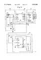
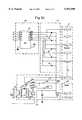
- the systemincludes a pad for contacting a user of the system; a vibratory transducer having an eccentric element for vibrating the pad at variable intensity in response to a power signal; means for connecting an audio source to provide an audio signal; a detector circuit for producing a control signal as an amplitude envelope of the audio signal; and a coupler for producing the power signal in response to a control signal.
- the detector circuitcan include a detector diode connected for feeding an integrating filter.
- the systemfurther includes an audio filter for selecting a desired frequency response to the audio signal.
- the couplercan be a power amplifier that can include a pass transistor or alternatively, a pulse-width modulator.
Landscapes
- Health & Medical Sciences (AREA)
- Epidemiology (AREA)
- Pain & Pain Management (AREA)
- Physical Education & Sports Medicine (AREA)
- Rehabilitation Therapy (AREA)
- Life Sciences & Earth Sciences (AREA)
- Animal Behavior & Ethology (AREA)
- General Health & Medical Sciences (AREA)
- Public Health (AREA)
- Veterinary Medicine (AREA)
- Percussion Or Vibration Massage (AREA)
Abstract
Description
Claims (13)
Priority Applications (1)
| Application Number | Priority Date | Filing Date | Title |
|---|---|---|---|
| US08/779,860US5951500A (en) | 1997-01-03 | 1997-01-03 | Audio responsive massage system |
Applications Claiming Priority (1)
| Application Number | Priority Date | Filing Date | Title |
|---|---|---|---|
| US08/779,860US5951500A (en) | 1997-01-03 | 1997-01-03 | Audio responsive massage system |
Publications (1)
| Publication Number | Publication Date |
|---|---|
| US5951500Atrue US5951500A (en) | 1999-09-14 |
Family
ID=25117803
Family Applications (1)
| Application Number | Title | Priority Date | Filing Date |
|---|---|---|---|
| US08/779,860Expired - Fee RelatedUS5951500A (en) | 1997-01-03 | 1997-01-03 | Audio responsive massage system |
Country Status (1)
| Country | Link |
|---|---|
| US (1) | US5951500A (en) |
Cited By (42)
| Publication number | Priority date | Publication date | Assignee | Title |
|---|---|---|---|---|
| US6120468A (en)* | 1999-06-11 | 2000-09-19 | Tseng; Chin-Chun | Sound-controllable multistage massager equipped with LCD device |
| WO2001019316A3 (en)* | 1999-09-15 | 2001-11-15 | Niagara Mfg Ltd | A vibratory therapy apparatus |
| US20020075161A1 (en)* | 2000-09-27 | 2002-06-20 | Raffel Mark J. | Universal remote control system |
| US20030002682A1 (en)* | 2001-07-02 | 2003-01-02 | Phonex Broadband Corporation | Wireless audio/mechanical vibration transducer and audio/visual transducer |
| US6592533B1 (en)* | 1999-04-14 | 2003-07-15 | Toshiba Tec Kabushiki Kaisha | Air massager |
| US20030195441A1 (en)* | 2002-04-16 | 2003-10-16 | Parviz Firouzgar | Remotely controllable stimulator system and device |
| US20030225350A1 (en)* | 2002-05-31 | 2003-12-04 | Swidler Steven A. | Impact table system and method |
| US20040008104A1 (en)* | 2002-07-12 | 2004-01-15 | Endsley David E. | System and method for providing a synchronization signal |
| US6682494B1 (en)* | 1999-08-17 | 2004-01-27 | Inseat Solutions, Llc | Massaging system having isolated vibrators |
| US20040133133A1 (en)* | 2003-01-07 | 2004-07-08 | Samantha Dreimann | Massage device |
| US20040143201A1 (en)* | 2003-01-17 | 2004-07-22 | Hiro Moriyasu | Method of supporting and fastening for effective energy transfer utilizing a vibrating motor for a floor mat application |
| US6785922B2 (en) | 2001-12-27 | 2004-09-07 | Kolcraft Enterprises, Inc. | Mattress with internal vibrator |
| US20050036636A1 (en)* | 1999-10-22 | 2005-02-17 | Yamaha Corporation | Vibration source driving device |
| US20050107830A1 (en)* | 2003-11-18 | 2005-05-19 | Huang Chih J. | Electrotherapeutic apparatus for programming and memorizing modulated medium frequency carrier waves |
| US20070032752A1 (en)* | 2005-08-05 | 2007-02-08 | Hsin-Tsai Wu | Furniture with an inflatable body |
| US20070032753A1 (en)* | 2005-08-02 | 2007-02-08 | Hoffmann Michael R | Musical massage device |
| US20070179412A1 (en)* | 2006-02-01 | 2007-08-02 | Jimmyjane, Inc. | Inductively chargeable massager |
| US20080129094A1 (en)* | 2006-12-01 | 2008-06-05 | Yuichi Nakajima | Vibro-acoustic system |
| US20080296291A1 (en)* | 2005-06-06 | 2008-12-04 | Hiromi Nanba | Warm Wave Generating System |
| US20080306417A1 (en)* | 2006-02-01 | 2008-12-11 | Imboden Ethan F | Rechargeable personal massager |
| EP1350502A4 (en)* | 2000-12-08 | 2009-04-01 | Family Co Ltd | Massage machine, information recorded medium, program writing method |
| US20110054240A1 (en)* | 2009-09-03 | 2011-03-03 | Bender Eddie L | Induced Relaxation And Therapeutic Apparatus And Method |
| US20110054242A1 (en)* | 2009-09-03 | 2011-03-03 | Bender Eddie L | Induced Relaxation And Therapeutic Apparatus And Method |
| US20110071445A1 (en)* | 2009-08-26 | 2011-03-24 | Imboden Ethan F | Massage device with flexible substructure |
| US20110251535A1 (en)* | 2009-09-03 | 2011-10-13 | Bender Eddie L | Induced Relaxation and Therapeutic Apparatus and Method |
| US20120179077A1 (en)* | 2011-01-10 | 2012-07-12 | Tuck Cleve R | Vibrator apparatus with audio and motor control features |
| US20130061736A1 (en)* | 2011-09-09 | 2013-03-14 | Tomokuni Wauke | Vibration generator |
| US20130076090A1 (en)* | 2010-06-25 | 2013-03-28 | Tae Gyun Kim | Vibration converting chair |
| US20130130754A1 (en)* | 2005-04-04 | 2013-05-23 | Research In Motion Limited | Mobile wireless communications device having improved antenna impedance match and antenna gain from rf energy |
| US8463389B1 (en) | 2010-03-31 | 2013-06-11 | Richard Oths | Multi-sensory system and method for providing neuromuscular stimulation |
| US8517911B1 (en) | 2004-07-17 | 2013-08-27 | Jeffrey D. Thompson | Sound delivery system for vibro-acoustic treatment |
| CN104298285A (en)* | 2014-09-25 | 2015-01-21 | 深圳市无碍互动科技开发有限公司 | Vibrating ball capable of being charged wirelessly and intelligent control system thereof |
| US20160106621A1 (en)* | 2013-05-30 | 2016-04-21 | Vibrant Medical Limited | Device for treatment of peripheral arterial disease and micro-angiopathy in lower limbs |
| WO2016161450A1 (en)* | 2015-04-03 | 2016-10-06 | Sonicsensory, Llc | A modular system for building variable interactive platforms and enclosures for deep multisensory immersion into audio and audio-visual entertainment |
| WO2017025204A1 (en)* | 2015-08-07 | 2017-02-16 | Brose Fahrzeugteile Gmbh & Co. Kommanditgesellschaft, Coburg | Method for activating massage units in a seat, control device for carrying out said method, and seat arrangement |
| US10039387B2 (en) | 2012-07-27 | 2018-08-07 | Jennifer Lynn Tarplee | Mattress foundation including vibration motors and mounting arrangements therefor |
| US10058188B2 (en) | 2012-07-27 | 2018-08-28 | Tempur-Pedic Management, Llc | Mattress foundation including vibration motor assemblies |
| WO2019092233A1 (en)* | 2017-11-13 | 2019-05-16 | Brose Fahrzeugteile Gmbh & Co. Kommanditgesellschaft, Bamberg | Method for operating an electromotive massage device of a seat |
| US20200010197A1 (en)* | 2018-07-09 | 2020-01-09 | Jefto Otovic | Aircraft seat dress covers with massage features |
| US20200206455A1 (en)* | 2017-07-25 | 2020-07-02 | Sensorial Processing Technology Barcelona, Sl | System and method for distributed sensory stimulation |
| US11847262B2 (en)* | 2017-11-13 | 2023-12-19 | Ck Materials Lab Co., Ltd. | Apparatus and method for providing haptic control signal |
| EP4291147A4 (en)* | 2021-02-12 | 2025-02-19 | Opus Immersive, Inc. | VIBROACOUSTIC THERAPY BED WITH STORABLE FORM FACTOR |
Citations (6)
| Publication number | Priority date | Publication date | Assignee | Title |
|---|---|---|---|---|
| US2821191A (en)* | 1953-09-23 | 1958-01-28 | Paii Arthur Yascha | Pulsating device |
| DE3237427A1 (en)* | 1982-10-08 | 1984-04-12 | Udo 8000 München Lichtenecker | Motor control device for driving a motor of a vibration massage device and devices operating in conjunction therewith |
| DE3526725A1 (en)* | 1985-07-26 | 1987-01-29 | Walter Becker | Circuit having indicating light-emitting diodes for massaging apparatuses and cushions, with and without heating |
| US4750208A (en)* | 1978-05-17 | 1988-06-07 | Bodysonic Kabushiki Kaisha | Audio-band electromechanical vibration converter |
| US4779615A (en)* | 1987-05-13 | 1988-10-25 | Frazier Richard K | Tactile stimulator |
| US5076260A (en)* | 1989-09-14 | 1991-12-31 | Bodysonic Kabushiki Kaisha | Sensible body vibration |
- 1997
- 1997-01-03USUS08/779,860patent/US5951500A/ennot_activeExpired - Fee Related
Patent Citations (6)
| Publication number | Priority date | Publication date | Assignee | Title |
|---|---|---|---|---|
| US2821191A (en)* | 1953-09-23 | 1958-01-28 | Paii Arthur Yascha | Pulsating device |
| US4750208A (en)* | 1978-05-17 | 1988-06-07 | Bodysonic Kabushiki Kaisha | Audio-band electromechanical vibration converter |
| DE3237427A1 (en)* | 1982-10-08 | 1984-04-12 | Udo 8000 München Lichtenecker | Motor control device for driving a motor of a vibration massage device and devices operating in conjunction therewith |
| DE3526725A1 (en)* | 1985-07-26 | 1987-01-29 | Walter Becker | Circuit having indicating light-emitting diodes for massaging apparatuses and cushions, with and without heating |
| US4779615A (en)* | 1987-05-13 | 1988-10-25 | Frazier Richard K | Tactile stimulator |
| US5076260A (en)* | 1989-09-14 | 1991-12-31 | Bodysonic Kabushiki Kaisha | Sensible body vibration |
Cited By (65)
| Publication number | Priority date | Publication date | Assignee | Title |
|---|---|---|---|---|
| US6592533B1 (en)* | 1999-04-14 | 2003-07-15 | Toshiba Tec Kabushiki Kaisha | Air massager |
| US6120468A (en)* | 1999-06-11 | 2000-09-19 | Tseng; Chin-Chun | Sound-controllable multistage massager equipped with LCD device |
| US6682494B1 (en)* | 1999-08-17 | 2004-01-27 | Inseat Solutions, Llc | Massaging system having isolated vibrators |
| WO2001019316A3 (en)* | 1999-09-15 | 2001-11-15 | Niagara Mfg Ltd | A vibratory therapy apparatus |
| US20050036636A1 (en)* | 1999-10-22 | 2005-02-17 | Yamaha Corporation | Vibration source driving device |
| US7253350B2 (en) | 1999-10-22 | 2007-08-07 | Yamaha Corporation | Vibration source driving device |
| US7301094B1 (en)* | 1999-10-22 | 2007-11-27 | Yamaha Corporation | Device for driving vibration source |
| US20020075161A1 (en)* | 2000-09-27 | 2002-06-20 | Raffel Mark J. | Universal remote control system |
| EP1350502A4 (en)* | 2000-12-08 | 2009-04-01 | Family Co Ltd | Massage machine, information recorded medium, program writing method |
| US20030002682A1 (en)* | 2001-07-02 | 2003-01-02 | Phonex Broadband Corporation | Wireless audio/mechanical vibration transducer and audio/visual transducer |
| US6785922B2 (en) | 2001-12-27 | 2004-09-07 | Kolcraft Enterprises, Inc. | Mattress with internal vibrator |
| US20030195441A1 (en)* | 2002-04-16 | 2003-10-16 | Parviz Firouzgar | Remotely controllable stimulator system and device |
| US20030225350A1 (en)* | 2002-05-31 | 2003-12-04 | Swidler Steven A. | Impact table system and method |
| US7338459B2 (en)* | 2002-05-31 | 2008-03-04 | Swidler Steven A | Impact table system and method |
| US20040008104A1 (en)* | 2002-07-12 | 2004-01-15 | Endsley David E. | System and method for providing a synchronization signal |
| US20040133133A1 (en)* | 2003-01-07 | 2004-07-08 | Samantha Dreimann | Massage device |
| US20040143201A1 (en)* | 2003-01-17 | 2004-07-22 | Hiro Moriyasu | Method of supporting and fastening for effective energy transfer utilizing a vibrating motor for a floor mat application |
| US7129845B2 (en)* | 2003-11-18 | 2006-10-31 | Chih Jung Huang | Electrotherapeutic apparatus for programming and memorizing modulated medium frequency carrier waves |
| US20050107830A1 (en)* | 2003-11-18 | 2005-05-19 | Huang Chih J. | Electrotherapeutic apparatus for programming and memorizing modulated medium frequency carrier waves |
| US8517911B1 (en) | 2004-07-17 | 2013-08-27 | Jeffrey D. Thompson | Sound delivery system for vibro-acoustic treatment |
| US20130130754A1 (en)* | 2005-04-04 | 2013-05-23 | Research In Motion Limited | Mobile wireless communications device having improved antenna impedance match and antenna gain from rf energy |
| US8594750B2 (en)* | 2005-04-04 | 2013-11-26 | Blackberry Limited | Mobile wireless communications device having improved antenna impedance match and antenna gain from RF energy |
| US20080296291A1 (en)* | 2005-06-06 | 2008-12-04 | Hiromi Nanba | Warm Wave Generating System |
| US20070032753A1 (en)* | 2005-08-02 | 2007-02-08 | Hoffmann Michael R | Musical massage device |
| US7402146B2 (en)* | 2005-08-05 | 2008-07-22 | Hsin-Tsai Wu | Furniture with an inflatable body and vibrator |
| US20070032752A1 (en)* | 2005-08-05 | 2007-02-08 | Hsin-Tsai Wu | Furniture with an inflatable body |
| US20080306417A1 (en)* | 2006-02-01 | 2008-12-11 | Imboden Ethan F | Rechargeable personal massager |
| US20070179413A1 (en)* | 2006-02-01 | 2007-08-02 | Jimmyjane, Inc. | Networkable personal care device |
| US7749178B2 (en) | 2006-02-01 | 2010-07-06 | Jimmyjane, Inc. | Inductively chargeable massager |
| US7815582B2 (en) | 2006-02-01 | 2010-10-19 | Jimmyjane, Inc. | Networkable personal care device |
| US9132058B2 (en) | 2006-02-01 | 2015-09-15 | LELO Inc. | Rechargeable personal massager |
| US20070179414A1 (en)* | 2006-02-01 | 2007-08-02 | Jimmyjane, Inc. | Wireless remote control massager |
| US20070179412A1 (en)* | 2006-02-01 | 2007-08-02 | Jimmyjane, Inc. | Inductively chargeable massager |
| US7938789B2 (en) | 2006-02-01 | 2011-05-10 | Jimmyjane, Inc. | Wireless remote control massager |
| US20080129094A1 (en)* | 2006-12-01 | 2008-06-05 | Yuichi Nakajima | Vibro-acoustic system |
| US20110071445A1 (en)* | 2009-08-26 | 2011-03-24 | Imboden Ethan F | Massage device with flexible substructure |
| US8821421B2 (en) | 2009-08-26 | 2014-09-02 | Jj Acquisition, Llc | Massage device with flexible substructure |
| US20110251535A1 (en)* | 2009-09-03 | 2011-10-13 | Bender Eddie L | Induced Relaxation and Therapeutic Apparatus and Method |
| US20110054242A1 (en)* | 2009-09-03 | 2011-03-03 | Bender Eddie L | Induced Relaxation And Therapeutic Apparatus And Method |
| US20110054240A1 (en)* | 2009-09-03 | 2011-03-03 | Bender Eddie L | Induced Relaxation And Therapeutic Apparatus And Method |
| US8463389B1 (en) | 2010-03-31 | 2013-06-11 | Richard Oths | Multi-sensory system and method for providing neuromuscular stimulation |
| US20130076090A1 (en)* | 2010-06-25 | 2013-03-28 | Tae Gyun Kim | Vibration converting chair |
| US20120179077A1 (en)* | 2011-01-10 | 2012-07-12 | Tuck Cleve R | Vibrator apparatus with audio and motor control features |
| US8657766B2 (en)* | 2011-01-10 | 2014-02-25 | Cleve R. Tuck | Vibrator apparatus with audio and motor control features |
| US8653352B2 (en)* | 2011-09-09 | 2014-02-18 | Alps Electric Co., Ltd. | Vibration generator |
| US20130061736A1 (en)* | 2011-09-09 | 2013-03-14 | Tomokuni Wauke | Vibration generator |
| US10039387B2 (en) | 2012-07-27 | 2018-08-07 | Jennifer Lynn Tarplee | Mattress foundation including vibration motors and mounting arrangements therefor |
| US10058188B2 (en) | 2012-07-27 | 2018-08-28 | Tempur-Pedic Management, Llc | Mattress foundation including vibration motor assemblies |
| US20160106621A1 (en)* | 2013-05-30 | 2016-04-21 | Vibrant Medical Limited | Device for treatment of peripheral arterial disease and micro-angiopathy in lower limbs |
| US10980705B2 (en)* | 2013-05-30 | 2021-04-20 | Vibrant Medical Limited | Device for treatment of peripheral arterial disease and micro-angiopathy in lower limbs |
| CN104298285A (en)* | 2014-09-25 | 2015-01-21 | 深圳市无碍互动科技开发有限公司 | Vibrating ball capable of being charged wirelessly and intelligent control system thereof |
| US10729974B2 (en)* | 2015-04-03 | 2020-08-04 | SonicSensory, Inc. | Modular system for building variable interactive platforms and enclosures for deep multisensory immersion into audio and audio-visual entertainment |
| US11759705B2 (en) | 2015-04-03 | 2023-09-19 | Haptech Holdings, Inc. | Modular system for building variable interactive platforms and enclosures for deep multisensory immersion into audio and audio-visual entertainment |
| US20180126263A1 (en)* | 2015-04-03 | 2018-05-10 | SonicSensory, Inc. | A modular system for building variable interactive platforms and enclosures for deep multisensory immersion into audio and audio-visual entertainment |
| WO2016161450A1 (en)* | 2015-04-03 | 2016-10-06 | Sonicsensory, Llc | A modular system for building variable interactive platforms and enclosures for deep multisensory immersion into audio and audio-visual entertainment |
| WO2017025204A1 (en)* | 2015-08-07 | 2017-02-16 | Brose Fahrzeugteile Gmbh & Co. Kommanditgesellschaft, Coburg | Method for activating massage units in a seat, control device for carrying out said method, and seat arrangement |
| US11046225B2 (en)* | 2015-08-07 | 2021-06-29 | Brose Fahrzeugteile Se & Co. Kg (Coburg) | Method for activating massage units in a seat, control device for carrying out said method, and seat arrangement |
| US11639127B2 (en) | 2015-08-07 | 2023-05-02 | Brose Fahrzeugteile Se & Co. Kg (Coburg) | Method for activating massage units in a seat, control device for carrying out said method, and seat arrangement |
| CN107921899A (en)* | 2015-08-07 | 2018-04-17 | 布罗泽汽车部件制造科堡有限公司 | For activate the massage unit in seat method, be used for realization the method control device and seat arrangement |
| US20200206455A1 (en)* | 2017-07-25 | 2020-07-02 | Sensorial Processing Technology Barcelona, Sl | System and method for distributed sensory stimulation |
| WO2019092233A1 (en)* | 2017-11-13 | 2019-05-16 | Brose Fahrzeugteile Gmbh & Co. Kommanditgesellschaft, Bamberg | Method for operating an electromotive massage device of a seat |
| US11847262B2 (en)* | 2017-11-13 | 2023-12-19 | Ck Materials Lab Co., Ltd. | Apparatus and method for providing haptic control signal |
| US12299202B2 (en) | 2017-11-13 | 2025-05-13 | Ck Materials Lab Co., Ltd. | Apparatus and method for providing haptic control signal |
| US20200010197A1 (en)* | 2018-07-09 | 2020-01-09 | Jefto Otovic | Aircraft seat dress covers with massage features |
| EP4291147A4 (en)* | 2021-02-12 | 2025-02-19 | Opus Immersive, Inc. | VIBROACOUSTIC THERAPY BED WITH STORABLE FORM FACTOR |
Similar Documents
| Publication | Publication Date | Title |
|---|---|---|
| US5951500A (en) | Audio responsive massage system | |
| US7304230B2 (en) | Multiple channel metronome | |
| US10154348B2 (en) | Systems and methods for improved acousto-haptic speakers | |
| US5807287A (en) | Massaging apparatus with audio signal control | |
| US4507816A (en) | Waterbed with sound wave system | |
| US5076260A (en) | Sensible body vibration | |
| US20040097852A1 (en) | Audio interactive sexual vibrator | |
| US4370602A (en) | Waterbed vibrator | |
| US5695455A (en) | Hydro-acoustic massage system and method | |
| JP3766221B2 (en) | Audio equipment | |
| KR102545268B1 (en) | Beauty device capable of controlling vibrating pattern | |
| US20080060129A1 (en) | Apparatus for vibration of a cot, cradle or the like | |
| US4371815A (en) | Waterbed vibrator | |
| JPH05293172A (en) | Relaxation system | |
| WO1998027923A1 (en) | Acoustic entertainment and therapy systems for water fixtures | |
| JPH07222781A (en) | Vibration sensor | |
| US20220295186A1 (en) | Shoulder-mounted speaker | |
| CN102114302A (en) | Method for stimulating nerves and adjusting hormone secretion | |
| JPH0218800B2 (en) | ||
| JPS6323494A (en) | Sound vibration equipment provided with massage signal source | |
| CN114979892B (en) | A sonic resonance system | |
| EP4461285A1 (en) | Apparatus for generating vibrational stimuli on the body of a user and support structure comprising such apparatus | |
| JP2923438B2 (en) | Cushion device | |
| KR200204423Y1 (en) | Apparatus driving for vibrator | |
| CN2622975Y (en) | Shell viberating loudspeaker |
Legal Events
| Date | Code | Title | Description |
|---|---|---|---|
| AS | Assignment | Owner name:JB RESEARCH, INC., CALIFORNIA Free format text:ASSIGNMENT OF ASSIGNORS INTEREST;ASSIGNOR:CUTLER, STANLEY;REEL/FRAME:008490/0821 Effective date:19970328 | |
| FEPP | Fee payment procedure | Free format text:PAYOR NUMBER ASSIGNED (ORIGINAL EVENT CODE: ASPN); ENTITY STATUS OF PATENT OWNER: SMALL ENTITY | |
| AS | Assignment | Owner name:JBR ACQUISITION LLC, CALIFORNIA Free format text:ASSIGNMENT OF ASSIGNORS INTEREST;ASSIGNOR:JB RESEARCH, INC.;REEL/FRAME:011944/0038 Effective date:20010228 | |
| AS | Assignment | Owner name:INSEAT SOLUTIONS LLC, CALIFORNIA Free format text:CHANGE OF NAME;ASSIGNOR:JBR ACQUISITION LLC;REEL/FRAME:012475/0130 Effective date:20010706 | |
| FEPP | Fee payment procedure | Free format text:PAYER NUMBER DE-ASSIGNED (ORIGINAL EVENT CODE: RMPN); ENTITY STATUS OF PATENT OWNER: SMALL ENTITY Free format text:PAYOR NUMBER ASSIGNED (ORIGINAL EVENT CODE: ASPN); ENTITY STATUS OF PATENT OWNER: SMALL ENTITY | |
| FPAY | Fee payment | Year of fee payment:4 | |
| REMI | Maintenance fee reminder mailed | ||
| LAPS | Lapse for failure to pay maintenance fees | ||
| STCH | Information on status: patent discontinuation | Free format text:PATENT EXPIRED DUE TO NONPAYMENT OF MAINTENANCE FEES UNDER 37 CFR 1.362 | |
| FP | Lapsed due to failure to pay maintenance fee | Effective date:20070914 |