US5951483A - Method and apparatus for detecting an internal pacemaker pulse - Google Patents
Method and apparatus for detecting an internal pacemaker pulseDownload PDFInfo
- Publication number
- US5951483A US5951483AUS09/013,236US1323698AUS5951483AUS 5951483 AUS5951483 AUS 5951483AUS 1323698 AUS1323698 AUS 1323698AUS 5951483 AUS5951483 AUS 5951483A
- Authority
- US
- United States
- Prior art keywords
- term energy
- lead
- long term
- short term
- energy
- Prior art date
- Legal status (The legal status is an assumption and is not a legal conclusion. Google has not performed a legal analysis and makes no representation as to the accuracy of the status listed.)
- Expired - Lifetime
Links
Images


Classifications
- A—HUMAN NECESSITIES
- A61—MEDICAL OR VETERINARY SCIENCE; HYGIENE
- A61B—DIAGNOSIS; SURGERY; IDENTIFICATION
- A61B5/00—Measuring for diagnostic purposes; Identification of persons
- A61B5/24—Detecting, measuring or recording bioelectric or biomagnetic signals of the body or parts thereof
- A61B5/316—Modalities, i.e. specific diagnostic methods
- A61B5/318—Heart-related electrical modalities, e.g. electrocardiography [ECG]
- A61B5/346—Analysis of electrocardiograms
- A61B5/349—Detecting specific parameters of the electrocardiograph cycle
- A—HUMAN NECESSITIES
- A61—MEDICAL OR VETERINARY SCIENCE; HYGIENE
- A61B—DIAGNOSIS; SURGERY; IDENTIFICATION
- A61B5/00—Measuring for diagnostic purposes; Identification of persons
- A61B5/72—Signal processing specially adapted for physiological signals or for diagnostic purposes
- A61B5/7203—Signal processing specially adapted for physiological signals or for diagnostic purposes for noise prevention, reduction or removal
Definitions
- the present inventionrelates generally to detecting pacing pulses generated by an internal pacemaker, and more particularly, to an external defibrillator/monitor capable of distinguishing an internal pacemaker pulse in an electrocardiogram signal.
- One of the more common treatments for diseased or damaged hearts which are incapable of producing electrical excitation pulsesi.e., the pulses necessary to begin contraction of the heart's ventricles and atria, is to implant an internal cardiac pacemaker.
- Internal cardiac pacemakerselectrically supply the necessary excitation pacing pulses directly to the heart through a set of electrodes. Such pacing pulses may be applied continuously if the heart is completely malfunctioning, or intermittently if it is only occasionally malfunctioning.
- Monitoring an electrocardiogram (ECG) signal from a patient having an internal pacemakeris difficult because pacing pulses generated by the internal pacemaker can interfere with the ECG signal and result in misdiagnosis of the heart's condition.
- ECGelectrocardiogram
- the QRS complex of the EGG signalis widened, which may falsely indicate acute myocardial infarction (AMI), a heart condition for which active therapy such as thrombolytic therapy is delivered.
- AMIacute myocardial infarction
- the pacing pulsewere to go undetected, a shockable heart rhythm could be mistakenly diagnosed by a ventricular fibrillation detection algorithm and a defibrillation shock applied.
- the ECG signal of a patient with an internal pacemaker who is experiencing asystolemay contain periodically occurring pacing pulses.
- asystoleis the cessation of heart activity and is indicated in the ECG signal by the absence of a QRS complex. Consequently, the presence of the pacing pulse may cause the asystole to go undetected.
- a method and apparatus for detecting internal pacemaker pulseswhich are small in both amplitude and duration are needed.
- the method and apparatusshould detect internal pacing pulses in the presence of noise with acceptable degrees of specificity and sensitivity. Further, the method and apparatus should provide a flexible range of energy values in which to detect a pacing pulse, so that as pacemaker technology advances, and pacing pulses become smaller, the method and apparatus of the present invention remains viable. As explained in the following, the present invention provides a method and apparatus that meets these criteria and solves other problems in the prior art.
- a method and apparatusare provided for detecting internal pacing pulses generated by an internal pacemaker.
- the method and apparatusmay be employed by any device capable of monitoring an ECG signal, such as a cardiac monitor or defibrillator.
- a 12-lead ECG signalis monitored by the present invention for possible pacing pulses.
- At least one of the twelve leadsis passed through a low pass filter followed by an analog-to-digital converter.
- the digitized lead signalis then applied to a digital bandpass filter to remove low and high frequency noise.
- a short term energy and a long term energyare computed.
- the short term energyconsists of mostly internal pacing pulse energy, while the long term energy essentially consists of the energy associated with background noise.
- a pacing pulseis detected if the ratio of the short term energy to the long term energy is greater than a predetermined threshold.
- a range of valuesis defined as a function of the predetermined threshold and absolute noise. Thus, if the ratio of short term energy to long term energy falls within this range, a pacing pulse is detected.
- the lead used to determine the short term energy and the long term energyis switched if too many pacing pulses have been detected within a predetermined time interval, and another lead may be used to determine the short and long term energies.
- An apparatus capable of performing the method described aboverepresents a further aspect of this invention.
- FIG. 1is a block diagram of an external cardiac defibrillator capable of detecting internal pacing pulses in accordance with the present invention
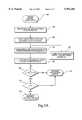
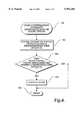
- FIGS. 2A and 2Bare flow charts illustrating the logic used by the defibrillator shown in FIG. 1 for detecting an internal pacing pulse
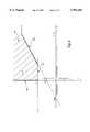
- FIG. 3is a graph illustrating a range of values in which indicate the presence of an internal pacing pulse.
- FIG. 4is a flow chart illustrating the logic used by the defibrillator shown in FIG. 1 to confirm which lead the defibrillator is using to detect internal pacing pulses in accordance with the logic shown in FIG. 2.
- FIG. 1is a block diagram of an external cardiac defibrillator 8 connected to a patient 25 that is capable of detecting pacing pulses generated by an internal pacemaker 26 in accordance with the present invention.
- the defibrillator 8analyzes a 12-lead electrocardiogram (ECG) signal of the patient 25 to identify a shockable heart rhythm and to detect internal pacing pulses.
- ECGelectrocardiogram
- the defibrillator 8stores electric charge and delivers the electric charge to the patient 25 in the form of an electric current pulse, i.e., a defibrillation pulse.
- the defibrillation pulseis applied to the patient 25 over a set of paddles 24.
- the defibrillator 8may contain more components than those shown in FIG. 1. However, a disclosure of the preferred embodiment of the present invention does not require that all of these general conventional components be shown. It will further be appreciated that the present invention may be implemented by a cardiac monitor having essentially the same components as the defibrillator 8 except that the monitor does not have the components necessary for delivering a defibrillation pulse.
- the defibrillator 8analyzes a 12-lead ECG signal of the patient to identify shockable and non-shockable heart rhythms and to detect internal pacing pulses.
- the ECG signalis received from a set of ten electrodes 30, i.e., four limb electrodes and six precordial electrodes placed on the patient's limbs and chest.
- the signals received from the ten electrodes 30are monitored by a monitoring circuit 18, which processes the ECG signals to derive 12 leads or waveforms.
- These 12 leadsare well known in the art as leads I, II, III, aVr, aVl, aVf and V1, V2, V3, V4, V5 and V6.
- the ECG signal associated with lead IIis used to detect internal pacing pulses. It has been empirically determined that lead II is most likely to be affected by an internal pacing pulse. Since the internal pacemaker 26 applies pacing pulses to either the right atrium of the heart or the left ventricle of the heart, it follows that lead II, which is generated from the right shoulder of the patient to the left leg of the patient and which provides the best view of the inferior portion of the heart, will be most affected by the pacing pulse generated. However, it will be appreciated that the present invention may use any of the other leads in order to detect an internal pacing signal and that, depending on the pacemaker 26 and the internal pacing pulse its generates, another lead may actually be more suitable.
- the lead II signalis passed by the monitoring circuit 18 through a low pass filter 28 with a cutoff frequency of 3000 Hz.
- the low pass filter 28is employed to remove aliasing which can distort the lead II signal.
- the low pass filtered lead II signalis then provided to an analog-to-digital converter 16 with a sampling rate of 10 KHz.
- a microprocessor 12analyzes the digital lead II signal provided by the analog-to-digital converter 16 in order to detect whether or not the patient's ECG signal contains an internal pacing pulse generated by the internal pacemaker 26.
- the monitor circuit 18is connected to an energy storage capacitor C to aid the microprocessor 12 in monitoring the voltage on the energy storage capacitor C as the capacitor is being charged. If a shockable rhythm is detected, the microprocessor 12 charges the energy storage capacitor C to a desired voltage, which in turn prepares the defibrillator 8 to apply a defibrillation pulse to the patient 25 using the paddles 24.
- the microprocessor 12is also connected to a display 10 and a control panel 11. Information is entered on the control panel 11 by a defibrillator operator to control the defibrillator.
- the display 10indicates to the operator the condition of the defibrillator 8 and the patient 25.
- FIG. 2Aillustrates the logic used by the microprocessor 12 in an embodiment of the present invention employing a fixed-point processor to evaluate the digital lead II signal to detect an internal pacing pulse.
- the microprocessor 12is a fixed-point processor, which requires that all calculations made in order to detect pacing pulses be performed in fixed-point arithmetic. As will be described in more detail below, this impacts the method implemented by the present invention to detect internal pacing pulses.
- a fixed-point processoris desirable from a cost and reduced computation standpoint, those of ordinary skill in the art will appreciate that a floating-point processor may also be used without departing from the scope of the present invention.
- FIG. 2Band as described in more detail below, a slightly different logic is used if the microprocessor 12 is a floating point processor.
- the logicbegins in a block 100 and proceeds to a block 102 where the digitized lead II signal is applied to a digital bandpass filter.
- a bandpass filteris used because the bandwidth of a pacing signal is significantly larger than the bandwidth of an ECG signal. Therefore, the noise and low frequency signals that may be present are removed.
- the bandpass filteris an infinite-duration impulse response (IIR) filter that is based on elliptic function. In the actual embodiment described herein, the bandpass filter passes 300 to 3500 Hz. Because the present invention uses energy in the passband, the nonlinear phase response of the passband filter is immaterial.
- the absolute value of the bandpass filtered lead II signalis determined in a block 104.
- the absolute value of the filtered signalis then used to compute a short term energy and a long term energy associated with the lead II signal. It will be appreciated by those of ordinary skill in the art, that by computing the short term energy and long term energy using the absolute value of the filtered lead II signal, only an approximation of the true short term energy and long term energy are computed. However, the fact that an approximation of these energies is used is immaterial to the detection of an internal pacing pulse. Consequently, the term "energy" will continue to be used in reference to these approximations for ease in explanation.
- the short term energy (s)is computed by summing the absolute value of the bandpass filtered signal over a short term interval, e.g., 1 msec.
- the short term energyis computed based on the assumption that if there exists an internal pacing pulse, the energy present in a signal of a short duration would be mostly due to the pacing pulse, rather than noise or some other factor, whose energy value cannot be quantified or is unknown.
- the duration of the short term intervalis determined to be 1 msec in the actual embodiment described herein because the main lobe width of the output of the bandpass filter is about 1 msec for a conventional narrow-width (0.1 msec) pacing pulse.
- the long term energy associated with the lead II signalis determined. More specifically, in a block 106 the absolute value of the lead II signal is subsampled at a predetermined rate, e.g., a factor of 10. In a block 108, the long term energy (r) is computed as the sum of the absolute value of the subsampled, bandpass filtered lead II signal over a long term interval, e.g., 50 msec.
- the long term energyis essentially a measurement of the background noise being experience by the system. The long term energy is computed based on the assumption that the energy associated with the internal pacing pulse will average out over the long term interval and thus, will not significantly impact the measurement of the background noise.
- An internal pacing pulseis detected as a function of the short term energy and the long term energy, i.e., if the ratio of the short term energy, which is likely comprised of mostly pacing pulse energy, and the long term energy, which is comprised of mostly background noise, is greater than some predetermined threshold, a pacing pulse must be present. In other words, if a pacing pulse exists, the ratio of the short term energy to the long term energy will be significantly larger than if no pacing pulse exists. This relationship is defined as follows:
- (k)is an empirically predetermined threshold.
- the predetermined threshold (k)is empirically determined using the standard measurement for white noise as a starting point.
- a pacing pulseis detected when the following two conditions are satisfied:
- coefficients and rdenote the short and long term energies
- the coefficients A, B and Care empirically determined constants.
- Ais a coefficient having approximately the same value as the predetermined threshold (k). However, the exact value for (k) cannot be accommodated by a fixed-point processor. Thus, another coefficient B is introduced to provide flexibility in determining the coefficient A.
- coefficient Cis assigned a value representing a measurement of absolute noise, i.e., a minimum level of noise that is being experienced by the system.
- FIG. 3is a graph illustrating the conditions posed by Equations (2) and (3) and how they define the range of short term and long term energy values which indicate the presence of a pacing pulse.
- the x axisdenotes long term energy values (r) and the y axis denotes short term energy values (s).
- rlong term energy values
- sshort term energy values
- Ais the slope of the line and B is the intercept of the line.
- Equation (3)as noted above is depicted in FIG. 3 as a line 148, i.e., s>C. Further, it is a given that both the short term energy (s) and the long term energy (r) are greater than or equal to zero. Consequently, a range or region 140 of short term and long term energy values which indicate a pacing pulse is bound by line 142, line 144 and line 148. In other words, any pair of short term energy and long term energy values that falls within these boundaries indicates the presence of an internal pacing pulse. It will be appreciated from the graph illustrated in FIG. 3 that the coefficients A and B and C can be modified in order to change the range of short term and long term energy values which indicate the presence of a pacing pulse.
- increasing the threshold coefficient Awill increase the specificity of the pulse detection, i.e., internal pacing pulses will be detected with fewer false alarms.
- decreasing the threshold coefficient Awill increase the sensitivity of the pulse detection, i.e., internal pacing pulses will be detected more frequently, but with greater false alarms.
- the logicdetermines whether or not the pair of long term energy and short term energy values falls within the bounded area 140 in FIG. 3 by first determining in a block 112 if the condition represented by Equation (2) has been met. If not, the pair of short term energy and long term energy values does not fall within the bounded range 140 and a no pacing pulse result is returned in a block 116. However, if the condition of decision block 112 is satisfied, the logic proceeds to a decision block 114 where it determines if the short term energy is greater than the coefficient C, which is the coefficient associated with absolute noise. This condition guards against the case where only noise is present, but the first condition is falsely satisfied.
- a no pacing pulse resultis returned in block 116.
- the logicreturns a pacing pulse result in a block 118. It will be appreciated that if a pacing pulse is detected, the microprocessor 12 filters out the detected internal pacing pulse from the incoming ECG signals when analyzing the signals for shockable and non-shockable heart rhythms or executing 12-lead ECG interpretation.
- FIG. 2BThe logic implemented by the microprocessor 12 if it is a floating point processor is illustrated in FIG. 2B.
- the logicbegins in a block 120 and proceeds to a block 122 where the digitized lead II signal is applied to a digital bandpass filter. This is the same digital bandpass filter as described above in connection with block 102 of FIG. 2A.
- the microprocessorsquares the bandpass filtered lead II signal, rather than taking its absolute value. The squared value is used rather than the absolute value since computational precision is not an issue with the floating point processor as it is with the fixed-point processor.
- the short term energy and long term energy computed using the squared valuesare a true computation of energy, rather than an approximation.
- the short term energy (s)is computed by summing the squared bandpass filtered lead II signal over a short term interval.
- the long term energy (r)is computed by first subsampling the squared bandpass filtered lead II signal at a predetermined rate, e.g., a factor of 10, in a block 126, and then summing the squared bandpass filtered lead II signal over a long term interval, e.g., 50 msec.
- a predetermined ratee.g., a factor of 10
- the logicproceeds to a decision block 132 where it is determined if the ratio of the short term energy (s) to the long term energy (r) is greater than a predetermined threshold (k) in accordance with Equation (1).
- the microprocessor 12 of this alternative embodiment of the present inventionis a floating point processor rather than a fixed-point processor, the computation of the ratio of short term energy to long term energy provides sufficient accuracy for detecting a pacing pulse. Consequently, if the result of decision block 132 is positive, a pacing pulse result will be returned in a block 136. However, if the ratio of the short term energy to the long term energy is not greater than the predetermined threshold, a no pacing pulse result will be returned in a block 134.
- the predetermined threshold (k)may be adjusted empirically using real data. Higher threshold values will increase specificity and lower threshold values will increase sensitivity. In the actual embodiment of the present invention described herein, the predetermined threshold value is 0.5.
- lead II signalsare preferably used to determine if an internal pacing pulse is present.
- the lead II informationmay eventually prove unreliable. Consequently, it is a further aspect of the present invention to confirm the lead it is using to detect internal pacing pulses.
- the logic employed by the microprocessor 12 to confirm which lead it is usingis shown in FIG. 4. The logic begins in a block 150 upon an interruption caused by the detection of a pacing pulse in accordance with the logic shown in FIGS. 2A or 2B. The logic proceeds from a block 150 to a block 152 where the output of the pacing detection routine shown in FIGS.
- the logicdetermines if too many pacing pulses have been detected within a different predefined time interval. For example, in one embodiment of the present invention, the logic determines if more than four pacing pulses have been detected over the last second.
- the microprocessor 12switches leads and begins using a different lead in order to detect internal pacing pulses. Consequently, the logic shown in FIGS. 2A or 2B will begin analyzing information from a different lead.
- the V4 leadis used. Although the V-leads often do not measure the atria pulses very well, the V4 lead has been empirically determined to collect the most reliable data. However, as noted above, any of the 12 leads may be proven more suitable under certain conditions and thus, the lead confirmation routine shown in FIG. 4 may switch to the more suitable lead.
- microprocessor 12will continue to switch between lead II and lead V4 if the circumstances so require.
- logic shown in FIG. 4can be modified so as to switch between any combination or subset of leads. After the lead has been switched in a block 156, the logic ends in a block 158.
- any of short term or long term intervals used to compute the short term or long term energies, respectivelymay be lengthened or shortened as necessary to fine tune detection to varying pacing pulses.
- the rate at which the digital bandpass filtered signal is subsampled before being used to compute the long term energymay be increased or decreased as necessary to compensate for microprocessor limitations.
- the frequencies at which any of the signals are filteredcan also be changed in order to compensate for varying pacing pulses or noise levels. Accordingly, it is not intended that the scope of the invention be limited by the disclosure of the actual embodiments described above. Instead, the invention should be determined entirely by reference to the claims that follow.
Landscapes
- Health & Medical Sciences (AREA)
- Life Sciences & Earth Sciences (AREA)
- Engineering & Computer Science (AREA)
- Cardiology (AREA)
- Surgery (AREA)
- Medical Informatics (AREA)
- Signal Processing (AREA)
- Physics & Mathematics (AREA)
- Veterinary Medicine (AREA)
- Biophysics (AREA)
- Pathology (AREA)
- Biomedical Technology (AREA)
- Heart & Thoracic Surgery (AREA)
- Public Health (AREA)
- Molecular Biology (AREA)
- General Health & Medical Sciences (AREA)
- Animal Behavior & Ethology (AREA)
- Artificial Intelligence (AREA)
- Physiology (AREA)
- Computer Vision & Pattern Recognition (AREA)
- Psychiatry (AREA)
- Electrotherapy Devices (AREA)
Abstract
Description
s/r>k (1)
s-(A*r)-B>0 (2)
s-C>0 (3)
Ar+B<s (4)
Claims (25)
Priority Applications (1)
| Application Number | Priority Date | Filing Date | Title |
|---|---|---|---|
| US09/013,236US5951483A (en) | 1998-01-26 | 1998-01-26 | Method and apparatus for detecting an internal pacemaker pulse |
Applications Claiming Priority (1)
| Application Number | Priority Date | Filing Date | Title |
|---|---|---|---|
| US09/013,236US5951483A (en) | 1998-01-26 | 1998-01-26 | Method and apparatus for detecting an internal pacemaker pulse |
Publications (1)
| Publication Number | Publication Date |
|---|---|
| US5951483Atrue US5951483A (en) | 1999-09-14 |
Family
ID=21758930
Family Applications (1)
| Application Number | Title | Priority Date | Filing Date |
|---|---|---|---|
| US09/013,236Expired - LifetimeUS5951483A (en) | 1998-01-26 | 1998-01-26 | Method and apparatus for detecting an internal pacemaker pulse |
Country Status (1)
| Country | Link |
|---|---|
| US (1) | US5951483A (en) |
Cited By (14)
| Publication number | Priority date | Publication date | Assignee | Title |
|---|---|---|---|---|
| US20060020219A1 (en)* | 2004-06-30 | 2006-01-26 | Zinser Richard L Jr | Method and system for detecting pace pulses |
| US20060094973A1 (en)* | 2004-10-29 | 2006-05-04 | Drew Touby A | Division approximation for implantable medical devices |
| US20060173265A1 (en)* | 2003-01-25 | 2006-08-03 | Tae-Song Kim | Method and apparatus for receiving data in human body communication system |
| EP1724684A1 (en)* | 2005-05-17 | 2006-11-22 | BUSI Incubateur d'entreprises d'AUVEFGNE | System and method for task scheduling, signal analysis and remote sensor |
| CN100337583C (en)* | 2004-07-26 | 2007-09-19 | 深圳迈瑞生物医疗电子股份有限公司 | Method and circuit for measuring of inhibiting electrocardiac waveforms by suppressing pace make pulse |
| CN103110415A (en)* | 2013-02-01 | 2013-05-22 | 深圳市理邦精密仪器股份有限公司 | Detection device and method for pace-making signal |
| CN103239223A (en)* | 2013-05-17 | 2013-08-14 | 深圳邦健生物医疗设备股份有限公司 | Pace-making signal detection method and device and medical instrument |
| CN104382586A (en)* | 2014-11-28 | 2015-03-04 | 深圳邦健生物医疗设备股份有限公司 | Electric shock signal detecting method and device |
| CN104939820A (en)* | 2015-05-28 | 2015-09-30 | 深圳市理邦精密仪器股份有限公司 | Pacing signal detection method and device |
| US10154794B2 (en) | 2014-04-25 | 2018-12-18 | Medtronic, Inc. | Implantable cardioverter-defibrillator (ICD) tachyarrhythmia detection modifications responsive to detected pacing |
| US10226197B2 (en) | 2014-04-25 | 2019-03-12 | Medtronic, Inc. | Pace pulse detector for an implantable medical device |
| US10448855B2 (en) | 2014-04-25 | 2019-10-22 | Medtronic, Inc. | Implantable medical device (IMD) sensing modifications responsive to detected pacing pulses |
| CN116196011A (en)* | 2023-01-31 | 2023-06-02 | 江苏正心智能科技有限公司 | Embedded low-power-consumption real-time electrocardio pacing signal detection method |
| US11841264B2 (en)* | 2019-02-22 | 2023-12-12 | Blackberry Limited | Method and system for cargo loading detection |
Citations (22)
| Publication number | Priority date | Publication date | Assignee | Title |
|---|---|---|---|---|
| US4527567A (en)* | 1980-04-01 | 1985-07-09 | Yeda Research & Development Company, Ltd. | Method and apparatus for automatically evaluating the quality of the performance of a cardiac pacing system |
| US4830006A (en)* | 1986-06-17 | 1989-05-16 | Intermedics, Inc. | Implantable cardiac stimulator for detection and treatment of ventricular arrhythmias |
| US4880004A (en)* | 1988-06-07 | 1989-11-14 | Intermedics, Inc. | Implantable cardiac stimulator with automatic gain control and bandpass filtering in feedback loop |
| US5000189A (en)* | 1989-11-15 | 1991-03-19 | Regents Of The University Of Michigan | Method and system for monitoring electrocardiographic signals and detecting a pathological cardiac arrhythmia such as ventricular tachycardia |
| US5033473A (en)* | 1989-10-24 | 1991-07-23 | Hewlett-Packard Company | Method for discriminating pace pulse tails |
| US5074308A (en)* | 1990-09-26 | 1991-12-24 | Siemens-Pacesetter, Inc. | System and method for recognizing pacemaker-mediated tachycardia |
| US5103819A (en)* | 1990-06-20 | 1992-04-14 | Intermedics, Inc. | Implantable cardiac stimulator with state machine for automatically controlling gain |
| US5144947A (en)* | 1990-04-03 | 1992-09-08 | Telectronics Pacing Systems, Inc. | Apparatus and method for antitachycardia pacing in a arrhythmia control systems |
| US5184615A (en)* | 1991-03-08 | 1993-02-09 | Telectronics Pacing Systems, Inc. | Apparatus and method for detecting abnormal cardiac rhythms using evoked potential measurements in an arrhythmia control system |
| US5217021A (en)* | 1991-07-30 | 1993-06-08 | Telectronics Pacing Systems, Inc. | Detection of cardiac arrhythmias using correlation of a cardiac electrical signals and temporal data compression |
| US5231990A (en)* | 1992-07-09 | 1993-08-03 | Spacelabs, Medical, Inc. | Application specific integrated circuit for physiological monitoring |
| US5312447A (en)* | 1992-09-24 | 1994-05-17 | Vitatron Medical, B.V. | Pacemaker with improved inhibit and trigger control |
| US5312451A (en)* | 1991-12-31 | 1994-05-17 | Ela Medical | Apparatus and methods for controlling a cardiac pacemaker in the event of a ventricular extrasystole |
| US5376104A (en)* | 1992-02-07 | 1994-12-27 | Nihon Kohden Corporation | Defibrillator with electrocardiogram monitor |
| US5391187A (en)* | 1994-02-22 | 1995-02-21 | Zmd Corporation | Semiautomatic defibrillator with heart rate alarm driven by shock advisory algorithm |
| US5447518A (en)* | 1993-08-31 | 1995-09-05 | Ventritex, Inc. | Method and apparatus for phase related cardiac defibrillation |
| US5448997A (en)* | 1993-10-15 | 1995-09-12 | Medtronic, Inc. | Heart pacing pulse detection system |
| US5488553A (en)* | 1993-12-15 | 1996-01-30 | Pacesetter, Inc. | Power converter apparatus for defibrillating cardiac pacemaker |
| US5507778A (en)* | 1994-02-22 | 1996-04-16 | Zmd Corporation | Semiautomatic defibrillator with synchronized shock delivery |
| US5545185A (en)* | 1994-12-23 | 1996-08-13 | Stephen Denker | Cardiac pacer which compensates for effects of abrupt changes in heart rate |
| US5545182A (en)* | 1994-09-21 | 1996-08-13 | Intermedics, Inc. | Cardioverter/defibrillator shock timing function |
| US5660184A (en)* | 1995-05-15 | 1997-08-26 | Johnson & Johnson Medical, Inc. | Pacemaker pulse detection and artifact rejection |
- 1998
- 1998-01-26USUS09/013,236patent/US5951483A/ennot_activeExpired - Lifetime
Patent Citations (23)
| Publication number | Priority date | Publication date | Assignee | Title |
|---|---|---|---|---|
| US4527567A (en)* | 1980-04-01 | 1985-07-09 | Yeda Research & Development Company, Ltd. | Method and apparatus for automatically evaluating the quality of the performance of a cardiac pacing system |
| US4830006A (en)* | 1986-06-17 | 1989-05-16 | Intermedics, Inc. | Implantable cardiac stimulator for detection and treatment of ventricular arrhythmias |
| US4830006B1 (en)* | 1986-06-17 | 1997-10-28 | Intermedics Inc | Implantable cardiac stimulator for detection and treatment of ventricular arrhythmias |
| US4880004A (en)* | 1988-06-07 | 1989-11-14 | Intermedics, Inc. | Implantable cardiac stimulator with automatic gain control and bandpass filtering in feedback loop |
| US5033473A (en)* | 1989-10-24 | 1991-07-23 | Hewlett-Packard Company | Method for discriminating pace pulse tails |
| US5000189A (en)* | 1989-11-15 | 1991-03-19 | Regents Of The University Of Michigan | Method and system for monitoring electrocardiographic signals and detecting a pathological cardiac arrhythmia such as ventricular tachycardia |
| US5144947A (en)* | 1990-04-03 | 1992-09-08 | Telectronics Pacing Systems, Inc. | Apparatus and method for antitachycardia pacing in a arrhythmia control systems |
| US5103819A (en)* | 1990-06-20 | 1992-04-14 | Intermedics, Inc. | Implantable cardiac stimulator with state machine for automatically controlling gain |
| US5074308A (en)* | 1990-09-26 | 1991-12-24 | Siemens-Pacesetter, Inc. | System and method for recognizing pacemaker-mediated tachycardia |
| US5184615A (en)* | 1991-03-08 | 1993-02-09 | Telectronics Pacing Systems, Inc. | Apparatus and method for detecting abnormal cardiac rhythms using evoked potential measurements in an arrhythmia control system |
| US5217021A (en)* | 1991-07-30 | 1993-06-08 | Telectronics Pacing Systems, Inc. | Detection of cardiac arrhythmias using correlation of a cardiac electrical signals and temporal data compression |
| US5312451A (en)* | 1991-12-31 | 1994-05-17 | Ela Medical | Apparatus and methods for controlling a cardiac pacemaker in the event of a ventricular extrasystole |
| US5376104A (en)* | 1992-02-07 | 1994-12-27 | Nihon Kohden Corporation | Defibrillator with electrocardiogram monitor |
| US5231990A (en)* | 1992-07-09 | 1993-08-03 | Spacelabs, Medical, Inc. | Application specific integrated circuit for physiological monitoring |
| US5312447A (en)* | 1992-09-24 | 1994-05-17 | Vitatron Medical, B.V. | Pacemaker with improved inhibit and trigger control |
| US5447518A (en)* | 1993-08-31 | 1995-09-05 | Ventritex, Inc. | Method and apparatus for phase related cardiac defibrillation |
| US5448997A (en)* | 1993-10-15 | 1995-09-12 | Medtronic, Inc. | Heart pacing pulse detection system |
| US5488553A (en)* | 1993-12-15 | 1996-01-30 | Pacesetter, Inc. | Power converter apparatus for defibrillating cardiac pacemaker |
| US5391187A (en)* | 1994-02-22 | 1995-02-21 | Zmd Corporation | Semiautomatic defibrillator with heart rate alarm driven by shock advisory algorithm |
| US5507778A (en)* | 1994-02-22 | 1996-04-16 | Zmd Corporation | Semiautomatic defibrillator with synchronized shock delivery |
| US5545182A (en)* | 1994-09-21 | 1996-08-13 | Intermedics, Inc. | Cardioverter/defibrillator shock timing function |
| US5545185A (en)* | 1994-12-23 | 1996-08-13 | Stephen Denker | Cardiac pacer which compensates for effects of abrupt changes in heart rate |
| US5660184A (en)* | 1995-05-15 | 1997-08-26 | Johnson & Johnson Medical, Inc. | Pacemaker pulse detection and artifact rejection |
Non-Patent Citations (6)
| Title |
|---|
| An Ambulatory Recording System for Pacemaker Follow Up , H. Ahlfeldt, T. Ahren, M. E. Nygards, I. Rinqvist, H. Svedlund, A. Walker and O. Wigertz, 1987.* |
| An Ambulatory Recording System for Pacemaker Follow-Up, H. Ahlfeldt, T. Ahren, M.-E. Nygards, I. Rinqvist, H. Svedlund, A. Walker and O. Wigertz, 1987. |
| Jussi Tranesjo, Thomas Fahraeus, Mats Erik Nygards and Ove Wigertz, Evaluation of New Equipment , Automatic Detection of Pacemaker Pulses in Ambulatory ECG Recording, PACE, vol. 5, Jan./Feb. 1982.* |
| Jussi Tranesjo, Thomas Fahraeus, Mats-Erik Nygards and Ove Wigertz, Evaluation of New Equipment, "Automatic Detection of Pacemaker Pulses in Ambulatory ECG Recording," PACE, vol. 5, Jan./Feb. 1982. |
| The Design and Evaluation of a New Hardware Pace Pulse Detector , Mousa N. Shaya and Barry L. Wyshogrod, 1988.* |
| The Design and Evaluation of a New Hardware Pace Pulse Detector, Mousa N. Shaya and Barry L. Wyshogrod, 1988. |
Cited By (26)
| Publication number | Priority date | Publication date | Assignee | Title |
|---|---|---|---|---|
| US7463918B2 (en)* | 2003-01-25 | 2008-12-09 | Korea Institute Of Science And Technology | Method and apparatus for receiving data in human body communication system |
| US20060173265A1 (en)* | 2003-01-25 | 2006-08-03 | Tae-Song Kim | Method and apparatus for receiving data in human body communication system |
| US20060020219A1 (en)* | 2004-06-30 | 2006-01-26 | Zinser Richard L Jr | Method and system for detecting pace pulses |
| US7471977B2 (en)* | 2004-06-30 | 2008-12-30 | General Electric Company | Method and system for detecting pace pulses |
| CN100337583C (en)* | 2004-07-26 | 2007-09-19 | 深圳迈瑞生物医疗电子股份有限公司 | Method and circuit for measuring of inhibiting electrocardiac waveforms by suppressing pace make pulse |
| US7848796B2 (en) | 2004-10-29 | 2010-12-07 | Medtronic, Inc. | Division approximation for implantable medical devices |
| US7526340B2 (en)* | 2004-10-29 | 2009-04-28 | Medtronic, Inc. | Division approximation for implantable medical devices |
| US20090198304A1 (en)* | 2004-10-29 | 2009-08-06 | Medtronic, Inc. | Division approximation for implantable medical devices |
| US20060094973A1 (en)* | 2004-10-29 | 2006-05-04 | Drew Touby A | Division approximation for implantable medical devices |
| EP1724684A1 (en)* | 2005-05-17 | 2006-11-22 | BUSI Incubateur d'entreprises d'AUVEFGNE | System and method for task scheduling, signal analysis and remote sensor |
| CN103110415A (en)* | 2013-02-01 | 2013-05-22 | 深圳市理邦精密仪器股份有限公司 | Detection device and method for pace-making signal |
| CN103239223B (en)* | 2013-05-17 | 2015-04-22 | 深圳邦健生物医疗设备股份有限公司 | Pace-making signal detection method and device and medical instrument |
| CN103239223A (en)* | 2013-05-17 | 2013-08-14 | 深圳邦健生物医疗设备股份有限公司 | Pace-making signal detection method and device and medical instrument |
| US10448855B2 (en) | 2014-04-25 | 2019-10-22 | Medtronic, Inc. | Implantable medical device (IMD) sensing modifications responsive to detected pacing pulses |
| US10154794B2 (en) | 2014-04-25 | 2018-12-18 | Medtronic, Inc. | Implantable cardioverter-defibrillator (ICD) tachyarrhythmia detection modifications responsive to detected pacing |
| US10226197B2 (en) | 2014-04-25 | 2019-03-12 | Medtronic, Inc. | Pace pulse detector for an implantable medical device |
| US10750970B2 (en) | 2014-04-25 | 2020-08-25 | Medtronic, Inc. | Implantable cardioverter-defibrillator (ICD) tachyarrhythmia detection modifications responsive to detected pacing |
| US11020038B2 (en) | 2014-04-25 | 2021-06-01 | Medtronic, Inc. | Pace pulse detector for a medical device |
| US11883179B2 (en) | 2014-04-25 | 2024-01-30 | Medtronic, Inc. | Implantable cardioverter-defibrillator (ICD) tachyarrhythmia detection modifications responsive to detected pacing |
| US12076153B2 (en) | 2014-04-25 | 2024-09-03 | Medtronic, Inc. | Pace pulse detector for a medical device |
| US12357221B2 (en) | 2014-04-25 | 2025-07-15 | Medtronic, Inc. | Implantable cardioverter-defibrillator (ICD) tachyarrhythmia detection modifications responsive to detected pacing |
| CN104382586A (en)* | 2014-11-28 | 2015-03-04 | 深圳邦健生物医疗设备股份有限公司 | Electric shock signal detecting method and device |
| CN104939820A (en)* | 2015-05-28 | 2015-09-30 | 深圳市理邦精密仪器股份有限公司 | Pacing signal detection method and device |
| CN104939820B (en)* | 2015-05-28 | 2017-12-19 | 深圳市理邦精密仪器股份有限公司 | A kind of pace-making signal detection method and device |
| US11841264B2 (en)* | 2019-02-22 | 2023-12-12 | Blackberry Limited | Method and system for cargo loading detection |
| CN116196011A (en)* | 2023-01-31 | 2023-06-02 | 江苏正心智能科技有限公司 | Embedded low-power-consumption real-time electrocardio pacing signal detection method |
Similar Documents
| Publication | Publication Date | Title |
|---|---|---|
| US5423863A (en) | Method of recognizing a ventricular cardiac pathological condition for automatic defibrillation purposes, and monitor-defibrillator for implementing said method | |
| EP2004285B1 (en) | Implantable medical device system and method with signal quality monitoring and response | |
| US5951483A (en) | Method and apparatus for detecting an internal pacemaker pulse | |
| EP2148722B1 (en) | Apparatus for subcutaneous ecg vector acceptability and selection | |
| EP1569720B1 (en) | Apparatus for discriminating polymorphic from monomorphic tachyarrhythmias | |
| US8160703B2 (en) | Apparatus, software, and methods for cardiac pulse detection using a piezoelectric sensor | |
| US8688203B2 (en) | Dual sensing for brady-tachy pacemaker/ICD | |
| US5497780A (en) | Apparatus for signal analysis of the electrical potential curve of heart excitation | |
| EP1569718B1 (en) | Systems for discriminating polymorphic from monomorphic tachyarrhythmias | |
| US6292694B1 (en) | Implantable medical device having atrial tachyarrhythmia prevention therapy | |
| US20070016257A1 (en) | Methods and apparatus for discriminating polymorphic tachyarrhythmias from monomorphic tachyarrhythmias facilitating detection of fibrillation | |
| US20030109790A1 (en) | Pulse detection method and apparatus using patient impedance | |
| US20090036788A1 (en) | Systems and methods for detection of vt and vf from remote sensing electrodes | |
| WO2000069517A1 (en) | Monitoring apparatus using wavelet transforms for the analysis of heart rhythms | |
| WO2000057781A1 (en) | Improved method for ischemia detection and apparatus | |
| WO2000057778A1 (en) | Method and apparatus for analyzing electrocardiogram signals | |
| EP3089786B1 (en) | Consistency monitoring for ecg shock advisory decisions | |
| CN112243387B (en) | Heart signal T wave detection | |
| US7403813B1 (en) | Systems and methods for detection of VT and VF from remote sensing electrodes | |
| US20210052180A1 (en) | Cardiac Monitoring System with Normally Conducted QRS Complex Identification | |
| US6823209B2 (en) | Electrocardiogram filter | |
| CN111407264B (en) | T wave over-sensing detection method and implantable medical equipment | |
| CN116849669A (en) | Electrocardiosignal signal processing system and defibrillator | |
| US6954671B1 (en) | Implantable heart stimulator or which identifies the origin of heart signals | |
| CN111407234B (en) | T wave over-sensing detection method and medical equipment |
Legal Events
| Date | Code | Title | Description |
|---|---|---|---|
| AS | Assignment | Owner name:PHYSIO-CONTROL MANUFACTURING CORPORATION, WASHINGT Free format text:ASSIGNMENT OF ASSIGNORS INTEREST;ASSIGNOR:JOO, TAE HONG;REEL/FRAME:009010/0927 Effective date:19980126 | |
| AS | Assignment | Owner name:AT&T CORP., NEW YORK Free format text:ASSIGNMENT OF ASSIGNORS INTEREST;ASSIGNORS:BRITZ, DAVID MICHAEL;DODLEY, JEEVAN PRAKASH;RUTLEDGE, CHRISTOPHER LEE;REEL/FRAME:009074/0484 Effective date:19980227 | |
| STCF | Information on status: patent grant | Free format text:PATENTED CASE | |
| FPAY | Fee payment | Year of fee payment:4 | |
| FPAY | Fee payment | Year of fee payment:8 | |
| FPAY | Fee payment | Year of fee payment:12 | |
| AS | Assignment | Owner name:PHYSIO-CONTROL, INC., WASHINGTON Free format text:ASSIGNMENT OF ASSIGNORS INTEREST;ASSIGNOR:PHYSIO-CONTROL MANUFACTURING, INC., F/K/A PHYSIO-CONTROL MANUFACTURING CORPORATION;REEL/FRAME:027612/0972 Effective date:20110127 | |
| AS | Assignment | Owner name:BANK OF NEW YORK MELLON TRUST COMPANY, N.A., AS *C Free format text:SECURITY AGREEMENT;ASSIGNOR:PHYSIO-CONTROL, INC.;REEL/FRAME:027765/0861 Effective date:20120130 | |
| AS | Assignment | Owner name:CITIBANK, N.A., AS COLLATERAL AGENT, NEW YORK Free format text:SECURITY AGREEMENT;ASSIGNOR:PHYSIO-CONTROL, INC.;REEL/FRAME:027763/0881 Effective date:20120130 | |
| AS | Assignment | Owner name:PHYSIO-CONTROL, INC., WASHINGTON Free format text:RELEASE BY SECURED PARTY;ASSIGNOR:THE BANK OF NEW YORK MELLON TRUST COMPANY, N.A.;REEL/FRAME:037519/0240 Effective date:20150605 | |
| AS | Assignment | Owner name:CITIBANK, N.A., AS COLLATERAL AGENT, NEW YORK Free format text:FIRST LIEN SECURITY AGREEMENT;ASSIGNORS:PHYSIO-CONTROL, INC.;PHYSIO-CONTROL INTERNATIONAL, INC.;REEL/FRAME:037532/0828 Effective date:20150605 | |
| AS | Assignment | Owner name:CITIBANK, N.A., AS COLLATERAL AGENT, NEW YORK Free format text:SECOND LIEN SECURITY AGREEMENT;ASSIGNORS:PHYSIO-CONTROL, INC.;PHYSIO-CONTROL INTERNATIONAL, INC.;REEL/FRAME:037559/0601 Effective date:20150605 | |
| AS | Assignment | Owner name:CITIBANK, N.A., AS COLLATERAL AGENT, NEW YORK Free format text:ABL SECURITY AGREEMENT;ASSIGNORS:PHYSIO-CONTROL, INC.;PHYSIO-CONTROL INTERNATIONAL, INC.;REEL/FRAME:037564/0902 Effective date:20150605 | |
| AS | Assignment | Owner name:PHYSIO-CONTROL, INC., WASHINGTON Free format text:RELEASE BY SECURED PARTY;ASSIGNOR:CITIBANK, N.A.;REEL/FRAME:038376/0806 Effective date:20160405 Owner name:PHYSIO-CONTROL INTERNATIONAL, INC., WASHINGTON Free format text:RELEASE BY SECURED PARTY;ASSIGNOR:CITIBANK, N.A.;REEL/FRAME:038378/0001 Effective date:20160405 Owner name:PHYSIO-CONTROL, INC., WASHINGTON Free format text:RELEASE BY SECURED PARTY;ASSIGNOR:CITIBANK, N.A.;REEL/FRAME:038378/0001 Effective date:20160405 Owner name:PHYSIO-CONTROL, INC., WASHINGTON Free format text:RELEASE BY SECURED PARTY;ASSIGNOR:CITIBANK, N.A.;REEL/FRAME:038378/0028 Effective date:20160405 Owner name:PHYSIO-CONTROL, INC., WASHINGTON Free format text:RELEASE BY SECURED PARTY;ASSIGNOR:CITIBANK, N.A.;REEL/FRAME:038379/0001 Effective date:20160405 Owner name:PHYSIO-CONTROL INTERNATIONAL, INC., WASHINGTON Free format text:RELEASE BY SECURED PARTY;ASSIGNOR:CITIBANK, N.A.;REEL/FRAME:038378/0028 Effective date:20160405 Owner name:PHYSIO-CONTROL INTERNATIONAL, INC., WASHINGTON Free format text:RELEASE BY SECURED PARTY;ASSIGNOR:CITIBANK, N.A.;REEL/FRAME:038379/0001 Effective date:20160405 |