US5951463A - Hand-held endoscopic viewing system - Google Patents
Hand-held endoscopic viewing systemDownload PDFInfo
- Publication number
- US5951463A US5951463AUS09/040,759US4075998AUS5951463AUS 5951463 AUS5951463 AUS 5951463AUS 4075998 AUS4075998 AUS 4075998AUS 5951463 AUS5951463 AUS 5951463A
- Authority
- US
- United States
- Prior art keywords
- assembly
- viewing
- eyepiece
- proximal end
- image bundle
- Prior art date
- Legal status (The legal status is an assumption and is not a legal conclusion. Google has not performed a legal analysis and makes no representation as to the accuracy of the status listed.)
- Expired - Lifetime
Links
Images


Classifications
- A—HUMAN NECESSITIES
- A61—MEDICAL OR VETERINARY SCIENCE; HYGIENE
- A61B—DIAGNOSIS; SURGERY; IDENTIFICATION
- A61B1/00—Instruments for performing medical examinations of the interior of cavities or tubes of the body by visual or photographical inspection, e.g. endoscopes; Illuminating arrangements therefor
- A61B1/00163—Optical arrangements
- A61B1/00195—Optical arrangements with eyepieces
- A—HUMAN NECESSITIES
- A61—MEDICAL OR VETERINARY SCIENCE; HYGIENE
- A61B—DIAGNOSIS; SURGERY; IDENTIFICATION
- A61B1/00—Instruments for performing medical examinations of the interior of cavities or tubes of the body by visual or photographical inspection, e.g. endoscopes; Illuminating arrangements therefor
- A61B1/04—Instruments for performing medical examinations of the interior of cavities or tubes of the body by visual or photographical inspection, e.g. endoscopes; Illuminating arrangements therefor combined with photographic or television appliances
- A61B1/042—Instruments for performing medical examinations of the interior of cavities or tubes of the body by visual or photographical inspection, e.g. endoscopes; Illuminating arrangements therefor combined with photographic or television appliances characterised by a proximal camera, e.g. a CCD camera
Definitions
- the fiber optic bundle and any associated connectorscan be generally referred to as a viewing assembly.
- the fiber optic bundleusually includes an image bundle that is a coherent bundle of image carrying fibers and at least one illumination carrying bundle or fiber.
- the image bundletypically cooperates with the focusing eyepiece.
- the end of the image bundleusually terminates in a connector that cooperates with the eyepiece.
- the illumination fibersare typically adapted to cooperate with a light source.
- the ends of the image bundle and the illumination fibersare usually coterminal at the distal end of the endoscope.
- the illumination fiberscarry light from a light source to the distal end of the endoscope in order to illuminate the area in front of the endoscope. An image of the illuminated area is then carried back through the endoscope to the eyepiece via the image bundle.
- endoscopic devicesalso include a handle that holds the eyepiece and the fiber optic bundle and associated connectors.
- Some hand held endoscopic viewing devicesinclude a power source and a light source associated with the handle.
- the handlecan be configured to connect to the fiber optic bundle and to the eyepiece to hold the entire system in operable relationship.
- endoscopesare also relatively complicated in structure. Since endoscopes are typically used for sterile surgical procedures, the complicated structure makes sterilization of the instrument difficult. Also, some sterilization procedures are harmful to eyepiece optics and other more delicate components. It would therefore be an advantage to provide an endoscopic viewing assembly that is relatively simple to manufacture and use and that is easily sterilized. A simplified, fixed focus eyepiece assembly that has no moving parts and that is sealed from the outside world would also be an advantage.
- the eyepiece assemblypreferably includes a body carrying focusing optics and having a distal portion and a proximal portion.
- the eyepiece assemblyfocuses and magnifies the image carried by the fiber optic image bundle.
- the body of the eyepiece assemblyis preferably cylindrical.
- the distal portion of the bodyincludes an optical aperture such as a window that defines a distal plane, and the focusing optics have a focal plane fixed substantially at the distal plane.
- the image bundlehas a proximal end that is substantially adjacent to the focal plane of the focusing optics when the eyepiece assembly and the viewing assembly are coupled.
- the proximal end of the image bundlepreferably is planar and flatly contacts the window of the eyepiece assembly when the eyepiece assembly and the viewing assembly are coupled.
- a handlecan also be provided in the preferred embodiment for holding the eyepiece assembly and the viewing assembly.
- the handleincludes a clasp that releasably engages the body of the eyepiece assembly and a first connector that releasably engages a second connector on the viewing assembly.
- the fixed-focus eyepiece assemblyprovides the advantage of quick and easy assembly and use with a viewing assembly. Also, the window of the eyepiece assembly provides a seal to protect the interior optical and mechanical components from liquids and foreign material. The liquid-tight seal allows the user to effectively clean the eyepiece assembly and assures compatibility with immersion methods of sterilization.
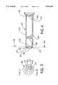
- FIG. 1is a side elevational view of an endoscopic viewing system of the present invention showing a viewing assembly coupled to an eyepiece assembly mounted on a handle;
- FIG. 2is a perspective view of the eyepiece assembly
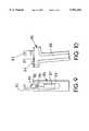
- FIG. 5is a partial side elevational view of the viewing assembly of FIG. 1 showing a coupling assembly and a second connector;
- FIG. 6is a cross-sectional view of the viewing assembly taken along line 6--6 of FIG. 5 and showing an image bundle and illumination fibers;
- FIG. 7is an end view of the viewing assembly showing the coupling assembly and the second connector
- FIG. 8is a partial cross-sectional view of the viewing assembly taken along line 8--8 of FIG. 7 showing the viewing assembly coupled to the eyepiece assembly;
- FIG. 9is a partial broken front view of the handle of the viewing system.
- FIG. 10is a side elevational view of the handle.
- FIG. 11is a side elevational view of an alternate embodiment of a viewing system.
- the viewing system 30includes an eyepiece assembly 40, a viewing assembly 60, and a handle 80.
- the eyepiece assembly 40includes a body 42 carrying focusing optics 44 and having a distal portion 46 and a proximal portion 48.
- the body 42is preferably cylindrical.
- the focusing optics 44include two groupings of lenses commonly referred to as doublets.
- the doublet closest to the distal portion 46is the objective 45
- the doublet closest to the proximal portion 48is the eyepiece doublet 47.
- the distal portion 46 of the eyepiece assembly 40includes an optical aperture 50 that allows light to pass into the body 42 and through the focusing optics 44.
- the optical aperture 50can be defined as a physical opening, but preferably is a window 52 that seals the inside of the eyepiece from the outside world.
- the outside surface of the window 52defines a distal plane 54 substantially perpendicular to the axis of the body 40.
- the optical aperture 50can be defined by a ring or similar structure that has an exterior surface that defines a contact surface for the distal plane. The contact surface is thus disposed about the optical aperture 50. Such a ring can be combined with the window.
- the window 52is preferably made of sapphire and the focusing optics 44 are made of optical quality glass.
- the focusing opticcan be made as is well known in the art.
- the viewing assembly 60includes a fiber optic image bundle 62 having a proximal region 63 terminating in a planar proximal end 64.
- the planar proximal end 64is substantially adjacent and preferably at the focal plane 56 when the eyepiece assembly 40 is coupled with the viewing assembly 60, as described in further detail below.
- the planar proximal end 64can be in contact with the window 52 or the contact surface discussed above. It is preferred that the planar proximal end be in flat contact with the window, i.e. its plane is the same as the focal plane 56.
- a coupling assembly 70is provided at the rearward portion 99 in the preferred embodiment.
- the coupling assembly 70is described in detail below.
- the image bundle 62is preferably part of a fiber optic bundle 66 that also includes illumination fibers 65 as shown in FIG. 6.
- a preferred embodiment of the fiber optic bundle 66includes seven illumination fibers 64 (also commonly referred to as light fibers) surrounding the image bundle 62.
- the illumination fibers 64preferably are about 500 ⁇ m in diameter.
- the fiber optic bundle 66further includes a jacket 68 surrounding the image bundle 62 and the illumination fibers 65.
- the jacket 68protects the bundle and fibers.
- a preferred embodiment of the viewing system 30also includes the coupling assembly 70 for coupling the viewing assembly 60 to the eyepiece assembly 40.
- the coupling assembly 70preferably includes a collar 71 on the viewing assembly 60 which engages a retaining ring 74 on the viewing assembly 60.
- the collar 71is preferably fixed to and surrounds the proximal end 64 of the image bundle 62.
- the retaining ring 74rotatably surrounds the collar 72.
- the collar 71includes a central raised portion 72 that has a proximal surface 73 that is substantially coplanar with the proximal end 64 of the image bundle 62.
- This coplanar configurationallows the proximal end 64 of the image bundle 62 to be fixed substantially at the focal plane 56 when the viewing assembly 60 is coupled to the eyepiece assembly 40.
- the proximal surface 73 of the central raised portion 72is coplanar with the proximal end 64, and the proximal end 64 and the proximal surface 73 together contact the window 52.
- the proximal surface 73can alternatively contact a contact surface as discussed above.
- the image carried to the proximal end 64can then be viewed without necessitating focusing adjustment.
- the retaining ring 74also includes a disk portion 75 that is unitary or integral with the cylindrical portion 76. As the retaining ring 74 is rotated to engage the mating ring 55, the cylindrical portion 76 and disk portion 75 are moved longitudinally toward the proximal surface 73 of the collar 71. The collar 71 is urged by the disk portion 75 toward the window 52 or contact surface until the proximal end 64 of the image bundle 62 contacts the window 52 or contact surface. At this point, the eyepiece and viewing assemblies are coupled, and the image carried by the image bundle 62 is substantially adjacent to the focal plane 56 and is viewable through the eyepiece assembly 40.
- FIGS. 9 and 10show a preferred embodiment of the handle 80 of the viewing system 30.
- the handle 80includes a clasp 82 and a first connector 84.
- the handle 80holds the eyepiece and viewing assemblies 40 and 60 by releasably engaging the body 42 of the eyepiece assembly 40 with the clasp 82.
- the clasp 82is preferably a generally C-shaped body that cooperates with the cylindrical body 42 of the eyepiece assembly 40.
- the combined eyepiece and viewing assembliesare mounted on the handle 80 by inserting a second connector 61 of the viewing assembly 60 in the first connector 84 and rotating the combination about the axis of the connectors until the body 42 is releasably engaged by the clasp 82.
- the handle 80includes a gripping portion 88 and a top side 90 spaced from the gripping portion 88.
- the first connector 84 and the clasp 82are located on the top side 90 in spaced relationship to each other.
- the first connector 84releasably engages the second connector 61 on the viewing assembly 60.
- the second connector 61preferably is disposed on the middle portion 98 of the housing 96 of the viewing assembly 60. As shown in FIGS. 5 and 8, the second connector 61 is at a generally perpendicular orientation on the housing 96 with respect to the axis of the coupling assembly 70.
- the first and second connectors 84 and 61preferably releasably engage each other in a snap fit manner, but can be embodied in any configuration known in the art.
- a power source 87can be provided within the handle to supply power to the illumination source 86.
- the illumination source 86is an incandescent lamp powered by four 1.5 volt AA lithium batteries.
- the power sourcecan be an external source of AC or DC current.
- the handle 80When the viewing system is assembled, the handle 80 supports the eyepiece assembly 40 and the viewing assembly 60 at two spaced-apart points. This configuration provides a stable viewing system that can be easily controlled by manipulation of the handle 80.
- Viewing system 130includes alternate embodiments of a viewing assembly 160 and a handle 180, but can include the previously described eyepiece assembly 40 of FIGS. 2-4.
- Handle 180includes a clasp 182, a first connector 184, a gripping portion 188, a top side 190, and a front side 191; the top and front sides 190 and 191 being spaced from the gripping portion 188.
- the clasp 182is located on the top side 190, but in this alternate embodiment, the eyepiece assembly 140 is releasably engaged with the clasp 182 by inserting the eyepiece assembly 140 downwardly into the clasp 182.
- the clasp 182releasably engages the eyepiece assembly 140 by frictionally gripping the body 142 of the eyepiece assembly 140.
- the first connector 184 of the alternate embodimentis located on the front side 191 of the handle 180.
- the alternate location of the first connector 184necessitates an alternate embodiment of the viewing assembly 160 so that the components can all be operably associated as previously described with respect to the preferred embodiment.
- the viewing assembly 160 shown in FIG. 11includes a second connector 161, a coupling assembly 170, and a junction body 195.
- a fiber optic bundle 166extends distally from the junction body 195 and includes an image bundle 162 and illumination fibers 165, as shown in FIG. 11. Proximal of the junction body 195, the image bundle 162 and the illumination fibers 165 extend separately from each other.
- Image bundle 162includes a planar proximal end 164.
- the illumination fibers 165terminate in a second connector 161, and the image bundle 162 terminates in a coupling assembly 170.
- Second connector 161is releasably engaged with first connector 184 on the handle 180, and coupling assembly 170 is releasably engaged with an eyepiece assembly 140.
- the viewing assembly 160includes the second connector 161 and the coupling assembly on separate extensions from the junction body 195, the viewing assembly 160 can be used with any number of handles that have the first connector 184 at any location such as, for example, on any side or at the bottom of the handle. Also, viewing assembly 160 can be used with an illumination source that is not included in the handle.
Landscapes
- Health & Medical Sciences (AREA)
- Life Sciences & Earth Sciences (AREA)
- Surgery (AREA)
- Biomedical Technology (AREA)
- Medical Informatics (AREA)
- Optics & Photonics (AREA)
- Pathology (AREA)
- Radiology & Medical Imaging (AREA)
- Biophysics (AREA)
- Engineering & Computer Science (AREA)
- Physics & Mathematics (AREA)
- Heart & Thoracic Surgery (AREA)
- Nuclear Medicine, Radiotherapy & Molecular Imaging (AREA)
- Molecular Biology (AREA)
- Animal Behavior & Ethology (AREA)
- General Health & Medical Sciences (AREA)
- Public Health (AREA)
- Veterinary Medicine (AREA)
- Endoscopes (AREA)
- Instruments For Viewing The Inside Of Hollow Bodies (AREA)
Abstract
Description
Claims (26)
Priority Applications (2)
| Application Number | Priority Date | Filing Date | Title |
|---|---|---|---|
| US09/040,759US5951463A (en) | 1998-03-18 | 1998-03-18 | Hand-held endoscopic viewing system |
| PCT/US1999/004811WO1999047882A1 (en) | 1998-03-18 | 1999-03-04 | Hand held endoscopic viewing system |
Applications Claiming Priority (1)
| Application Number | Priority Date | Filing Date | Title |
|---|---|---|---|
| US09/040,759US5951463A (en) | 1998-03-18 | 1998-03-18 | Hand-held endoscopic viewing system |
Publications (1)
| Publication Number | Publication Date |
|---|---|
| US5951463Atrue US5951463A (en) | 1999-09-14 |
Family
ID=21912786
Family Applications (1)
| Application Number | Title | Priority Date | Filing Date |
|---|---|---|---|
| US09/040,759Expired - LifetimeUS5951463A (en) | 1998-03-18 | 1998-03-18 | Hand-held endoscopic viewing system |
Country Status (2)
| Country | Link |
|---|---|
| US (1) | US5951463A (en) |
| WO (1) | WO1999047882A1 (en) |
Cited By (13)
| Publication number | Priority date | Publication date | Assignee | Title |
|---|---|---|---|---|
| US20030078476A1 (en)* | 2001-07-24 | 2003-04-24 | Hill Stephen D. | Apparatus for intubation |
| US6589165B2 (en)* | 2000-03-15 | 2003-07-08 | Surgical Optics Inc. | Modularly structured endoscope |
| US20040034311A1 (en)* | 2000-05-19 | 2004-02-19 | Albert Mihalcik | Guidewire with viewing capability |
| US6814698B2 (en) | 2001-10-05 | 2004-11-09 | Clarus Medical, Llc | Endoscope with flexible light guide having offset distal end |
| US20060020165A1 (en)* | 2004-07-26 | 2006-01-26 | Medtronic Xomed, Inc. | Disposable endoscope sheath having adjustable length |
| US20090225159A1 (en)* | 2008-03-07 | 2009-09-10 | Scott Schneider | Visual inspection device |
| US20100057045A1 (en)* | 2008-05-16 | 2010-03-04 | Albritton Iv Ford | Apparatus, system and method for manipulating a surgical catheter and working device with a single hand |
| US8382665B1 (en) | 2009-02-12 | 2013-02-26 | Alfred Fam | Endotracheal tube placement system and method |
| US20140103203A1 (en)* | 2012-10-17 | 2014-04-17 | The University Of Tokyo | Imaging Systems and Image Fiber Bundles for Downhole Measurement |
| US8942530B2 (en) | 2011-09-20 | 2015-01-27 | San Marino Capital, Inc. | Endoscope connector method and apparatus |
| US10709313B2 (en) | 2016-09-21 | 2020-07-14 | NCI, Inc. | Surgical instrument inspection system |
| US20230190079A1 (en)* | 2017-09-26 | 2023-06-22 | Olympus Winter & Ibe Gmbh | Endoscope |
| US12004724B2 (en) | 2021-05-06 | 2024-06-11 | Medtronic Xomed, Inc. | Endoscope cleaning system |
Citations (32)
| Publication number | Priority date | Publication date | Assignee | Title |
|---|---|---|---|---|
| US728589A (en)* | 1899-08-12 | 1903-05-19 | Leone Levi | Surgical instrument. |
| US2290665A (en)* | 1937-05-06 | 1942-07-21 | Walter A Arnesen | Diagnostic instrument |
| US3224320A (en)* | 1959-05-05 | 1965-12-21 | Slagteriernes Forskningsinst | Apparatus for determination of the distribution of meat and fat in slaughtered animals or parts thereof |
| US3297022A (en)* | 1963-09-27 | 1967-01-10 | American Cystoscope Makers Inc | Endoscope |
| US3434775A (en)* | 1965-04-23 | 1969-03-25 | Iota Cam Corp | Flexible fiber optic borescope |
| US4440157A (en)* | 1981-02-03 | 1984-04-03 | Olympus Optical Co., Ltd. | Hard endoscope |
| US4561446A (en)* | 1981-10-15 | 1985-12-31 | Siemens Aktiengesellschaft | Ultrasonic probe which can be introduced into a body |
| US4580198A (en)* | 1984-12-04 | 1986-04-01 | Zinnanti Jr Anthony | Illuminator for medical examination telescope |
| US4616630A (en)* | 1984-08-20 | 1986-10-14 | Fuji Photo Optical Co., Ltd. | Endoscope with an obtusely angled connecting section |
| US4624243A (en)* | 1985-04-08 | 1986-11-25 | American Hospital Supply Corp. | Endoscope having a reusable eyepiece and a disposable distal section |
| US4736733A (en)* | 1987-02-25 | 1988-04-12 | Medical Dynamics, Inc. | Endoscope with removable eyepiece |
| US4742818A (en)* | 1986-10-17 | 1988-05-10 | Baxter Travenol Laboratories, Inc. | Soakable eyepiece for endoscopes |
| US4762120A (en)* | 1983-11-08 | 1988-08-09 | Laserscope, Inc. | Endoscopic device having handle assembly and catheter assembly |
| US4782819A (en)* | 1987-02-25 | 1988-11-08 | Adair Edwin Lloyd | Optical catheter |
| US4784118A (en)* | 1987-04-28 | 1988-11-15 | Endotherapeutics | Optical viewing device |
| US4958932A (en)* | 1988-08-18 | 1990-09-25 | Mcdonnell Douglas Corporation | Optical measuring apparatus |
| US5088819A (en)* | 1989-12-30 | 1992-02-18 | Karl Storz | Endoscope, particularly industrial endoscope |
| US5125394A (en)* | 1990-12-03 | 1992-06-30 | Medical Concepts, Inc. | Endoscopic adapter with lamina interface |
| US5152278A (en)* | 1990-08-28 | 1992-10-06 | Applied Medical Resources, Inc. | Surgical endoscope apparatus |
| US5183031A (en)* | 1991-05-13 | 1993-02-02 | Rossoff Leonard J | Fiberoptic intubating laryngoscope |
| US5184602A (en)* | 1988-11-18 | 1993-02-09 | Effner Biomet Gmbh | Endoscope, in particular an arthroscope |
| US5215077A (en)* | 1989-11-09 | 1993-06-01 | Machida Endoscope Co., Ltd. | Direct vision/side vision exchangeable endoscope |
| US5359453A (en)* | 1992-02-19 | 1994-10-25 | United States Surgical Corporation | Optical viewing device |
| US5368014A (en)* | 1990-11-21 | 1994-11-29 | Effner Biomet Gmbh | Modular endoscope having easily replaceable parts |
| US5377668A (en)* | 1993-04-12 | 1995-01-03 | Optimed Technologies, Inc. | Apparatus and method for endoscopic diagnostics and therapy |
| US5582575A (en)* | 1994-02-23 | 1996-12-10 | Richard Wolf Gmbh | Instrument for endoscopic therapy |
| US5588950A (en)* | 1994-07-11 | 1996-12-31 | Asahi Kogaku Kogyo Kabushiki Kaisha | Portable endoscope system |
| US5588949A (en)* | 1993-10-08 | 1996-12-31 | Heartport, Inc. | Stereoscopic percutaneous visualization system |
| US5607386A (en)* | 1993-09-21 | 1997-03-04 | Flam; Gary H. | Malleable fiberoptic intubating stylet and method |
| US5630788A (en)* | 1994-08-12 | 1997-05-20 | Imagyn Medical, Inc. | Endoscope with curved end image guide |
| US5636625A (en)* | 1994-08-30 | 1997-06-10 | Machida Endoscope Co., Ltd. | Tracheal airway apparatus |
| US5645519A (en)* | 1994-03-18 | 1997-07-08 | Jai S. Lee | Endoscopic instrument for controlled introduction of tubular members in the body and methods therefor |
- 1998
- 1998-03-18USUS09/040,759patent/US5951463A/ennot_activeExpired - Lifetime
- 1999
- 1999-03-04WOPCT/US1999/004811patent/WO1999047882A1/enactiveApplication Filing
Patent Citations (32)
| Publication number | Priority date | Publication date | Assignee | Title |
|---|---|---|---|---|
| US728589A (en)* | 1899-08-12 | 1903-05-19 | Leone Levi | Surgical instrument. |
| US2290665A (en)* | 1937-05-06 | 1942-07-21 | Walter A Arnesen | Diagnostic instrument |
| US3224320A (en)* | 1959-05-05 | 1965-12-21 | Slagteriernes Forskningsinst | Apparatus for determination of the distribution of meat and fat in slaughtered animals or parts thereof |
| US3297022A (en)* | 1963-09-27 | 1967-01-10 | American Cystoscope Makers Inc | Endoscope |
| US3434775A (en)* | 1965-04-23 | 1969-03-25 | Iota Cam Corp | Flexible fiber optic borescope |
| US4440157A (en)* | 1981-02-03 | 1984-04-03 | Olympus Optical Co., Ltd. | Hard endoscope |
| US4561446A (en)* | 1981-10-15 | 1985-12-31 | Siemens Aktiengesellschaft | Ultrasonic probe which can be introduced into a body |
| US4762120A (en)* | 1983-11-08 | 1988-08-09 | Laserscope, Inc. | Endoscopic device having handle assembly and catheter assembly |
| US4616630A (en)* | 1984-08-20 | 1986-10-14 | Fuji Photo Optical Co., Ltd. | Endoscope with an obtusely angled connecting section |
| US4580198A (en)* | 1984-12-04 | 1986-04-01 | Zinnanti Jr Anthony | Illuminator for medical examination telescope |
| US4624243A (en)* | 1985-04-08 | 1986-11-25 | American Hospital Supply Corp. | Endoscope having a reusable eyepiece and a disposable distal section |
| US4742818A (en)* | 1986-10-17 | 1988-05-10 | Baxter Travenol Laboratories, Inc. | Soakable eyepiece for endoscopes |
| US4736733A (en)* | 1987-02-25 | 1988-04-12 | Medical Dynamics, Inc. | Endoscope with removable eyepiece |
| US4782819A (en)* | 1987-02-25 | 1988-11-08 | Adair Edwin Lloyd | Optical catheter |
| US4784118A (en)* | 1987-04-28 | 1988-11-15 | Endotherapeutics | Optical viewing device |
| US4958932A (en)* | 1988-08-18 | 1990-09-25 | Mcdonnell Douglas Corporation | Optical measuring apparatus |
| US5184602A (en)* | 1988-11-18 | 1993-02-09 | Effner Biomet Gmbh | Endoscope, in particular an arthroscope |
| US5215077A (en)* | 1989-11-09 | 1993-06-01 | Machida Endoscope Co., Ltd. | Direct vision/side vision exchangeable endoscope |
| US5088819A (en)* | 1989-12-30 | 1992-02-18 | Karl Storz | Endoscope, particularly industrial endoscope |
| US5152278A (en)* | 1990-08-28 | 1992-10-06 | Applied Medical Resources, Inc. | Surgical endoscope apparatus |
| US5368014A (en)* | 1990-11-21 | 1994-11-29 | Effner Biomet Gmbh | Modular endoscope having easily replaceable parts |
| US5125394A (en)* | 1990-12-03 | 1992-06-30 | Medical Concepts, Inc. | Endoscopic adapter with lamina interface |
| US5183031A (en)* | 1991-05-13 | 1993-02-02 | Rossoff Leonard J | Fiberoptic intubating laryngoscope |
| US5359453A (en)* | 1992-02-19 | 1994-10-25 | United States Surgical Corporation | Optical viewing device |
| US5377668A (en)* | 1993-04-12 | 1995-01-03 | Optimed Technologies, Inc. | Apparatus and method for endoscopic diagnostics and therapy |
| US5607386A (en)* | 1993-09-21 | 1997-03-04 | Flam; Gary H. | Malleable fiberoptic intubating stylet and method |
| US5588949A (en)* | 1993-10-08 | 1996-12-31 | Heartport, Inc. | Stereoscopic percutaneous visualization system |
| US5582575A (en)* | 1994-02-23 | 1996-12-10 | Richard Wolf Gmbh | Instrument for endoscopic therapy |
| US5645519A (en)* | 1994-03-18 | 1997-07-08 | Jai S. Lee | Endoscopic instrument for controlled introduction of tubular members in the body and methods therefor |
| US5588950A (en)* | 1994-07-11 | 1996-12-31 | Asahi Kogaku Kogyo Kabushiki Kaisha | Portable endoscope system |
| US5630788A (en)* | 1994-08-12 | 1997-05-20 | Imagyn Medical, Inc. | Endoscope with curved end image guide |
| US5636625A (en)* | 1994-08-30 | 1997-06-10 | Machida Endoscope Co., Ltd. | Tracheal airway apparatus |
Cited By (24)
| Publication number | Priority date | Publication date | Assignee | Title |
|---|---|---|---|---|
| US6589165B2 (en)* | 2000-03-15 | 2003-07-08 | Surgical Optics Inc. | Modularly structured endoscope |
| US20040034311A1 (en)* | 2000-05-19 | 2004-02-19 | Albert Mihalcik | Guidewire with viewing capability |
| US6929600B2 (en) | 2001-07-24 | 2005-08-16 | Stephen D. Hill | Apparatus for intubation |
| US20030078476A1 (en)* | 2001-07-24 | 2003-04-24 | Hill Stephen D. | Apparatus for intubation |
| US6814698B2 (en) | 2001-10-05 | 2004-11-09 | Clarus Medical, Llc | Endoscope with flexible light guide having offset distal end |
| US7811228B2 (en)* | 2004-07-26 | 2010-10-12 | Medtronic Xomed, Inc. | Disposable endoscope sheath having adjustable length |
| US20060020165A1 (en)* | 2004-07-26 | 2006-01-26 | Medtronic Xomed, Inc. | Disposable endoscope sheath having adjustable length |
| US9693024B2 (en) | 2008-03-07 | 2017-06-27 | Milwaukee Electric Tool Corporation | Visual inspection device |
| US20090225159A1 (en)* | 2008-03-07 | 2009-09-10 | Scott Schneider | Visual inspection device |
| US8189043B2 (en) | 2008-03-07 | 2012-05-29 | Milwaukee Electric Tool Corporation | Hand-held visual inspection device for viewing confined or difficult to access locations |
| US8659652B2 (en) | 2008-03-07 | 2014-02-25 | Milwaukee Electric Tool Corporation | Visual inspection device |
| US9986212B2 (en) | 2008-03-07 | 2018-05-29 | Milwaukee Electric Tool Corporation | Visual inspection device |
| US8988522B2 (en) | 2008-03-07 | 2015-03-24 | Milwaukee Electric Tool Corporation | Visual inspection device |
| US20100057045A1 (en)* | 2008-05-16 | 2010-03-04 | Albritton Iv Ford | Apparatus, system and method for manipulating a surgical catheter and working device with a single hand |
| US9011412B2 (en)* | 2008-05-16 | 2015-04-21 | Ford Albritton, IV | Apparatus, system and method for manipulating a surgical catheter and working device with a single hand |
| US8382665B1 (en) | 2009-02-12 | 2013-02-26 | Alfred Fam | Endotracheal tube placement system and method |
| US8942530B2 (en) | 2011-09-20 | 2015-01-27 | San Marino Capital, Inc. | Endoscope connector method and apparatus |
| US9549662B2 (en) | 2011-09-20 | 2017-01-24 | San Marino Capital, Inc. | Endoscope connector method and apparatus |
| US20140103203A1 (en)* | 2012-10-17 | 2014-04-17 | The University Of Tokyo | Imaging Systems and Image Fiber Bundles for Downhole Measurement |
| US8916816B2 (en)* | 2012-10-17 | 2014-12-23 | Schlumberger Technology Corporation | Imaging systems and image fiber bundles for downhole measurement |
| US10709313B2 (en) | 2016-09-21 | 2020-07-14 | NCI, Inc. | Surgical instrument inspection system |
| US20230190079A1 (en)* | 2017-09-26 | 2023-06-22 | Olympus Winter & Ibe Gmbh | Endoscope |
| US11889985B2 (en)* | 2017-09-26 | 2024-02-06 | Olympus Winter & Ibe Gmbh | Endoscope having eyepiece with first and second parts and electronic component arranged between the first and second parts |
| US12004724B2 (en) | 2021-05-06 | 2024-06-11 | Medtronic Xomed, Inc. | Endoscope cleaning system |
Also Published As
| Publication number | Publication date |
|---|---|
| WO1999047882A1 (en) | 1999-09-23 |
Similar Documents
| Publication | Publication Date | Title |
|---|---|---|
| US6276934B1 (en) | Dental camera | |
| EP0825837B1 (en) | Modular intra-oral imaging system video camera | |
| US7901351B2 (en) | Fiberoptic otoscope system | |
| EP0280384B1 (en) | Endoscope with removable eyepiece | |
| JP5132018B2 (en) | Zoom laparoscope | |
| JP3393539B2 (en) | Endoscope device | |
| US5662586A (en) | Hand held diagnostic instrument with video imaging | |
| US4756304A (en) | Arthroscopic video camera system | |
| US6398724B1 (en) | Focusable optical instrument with a sealed optical system having no internal optical moving parts | |
| US5682199A (en) | Video endoscope with interchangeable endoscope heads | |
| JPH0221041Y2 (en) | ||
| US5527262A (en) | Hand-held diagnostic dental probe with video imaging | |
| US5124797A (en) | Modular view lens attachment for micro video imaging camera | |
| US5528432A (en) | Intra-oral optical viewing device | |
| US5951463A (en) | Hand-held endoscopic viewing system | |
| EP0498114A1 (en) | Portable arthroscope with periscope optics | |
| US11337598B2 (en) | Laser video endoscope | |
| WO2011154970A1 (en) | Integrated fiber optic ophthalmic intraocular surgical device with camera | |
| US6855106B2 (en) | Endoscope and camera mount | |
| JP2001204647A (en) | Acusticus meatus endoscopic cleaning device | |
| EP0549097A1 (en) | Portable arthroscope with periscope optics | |
| JP3386187B2 (en) | Rigid endoscope device | |
| JP2009018081A (en) | Endoscope, endoscope body, and endoscope adapter | |
| IL123369A (en) | Dental camera | |
| JPH0410806B2 (en) |
Legal Events
| Date | Code | Title | Description |
|---|---|---|---|
| AS | Assignment | Owner name:TRANSAMERICA BUSINESS CREDIT CORPORATION, CALIFORN Free format text:SECURITY INTEREST;ASSIGNOR:CLARUS MEDICAL SYSTEMS, INC.;REEL/FRAME:009648/0416 Effective date:19981123 Owner name:TRANSAMERICA BUSINESS CREDIT CORPORATION, ILLINOIS Free format text:SECURITY INTEREST;ASSIGNOR:CLARUS MEDICAL SYSTEMS, INC.;REEL/FRAME:009648/0416 Effective date:19981123 | |
| AS | Assignment | Owner name:CLARUS MEDICAL SYSTEMS, INC., MINNESOTA Free format text:ASSIGNMENT OF ASSIGNORS INTEREST;ASSIGNORS:LOMBARDI, STEVE;RIEDL, CRAIG;BROWN, MARK F.;AND OTHERS;REEL/FRAME:010066/0275 Effective date:19990628 | |
| STCF | Information on status: patent grant | Free format text:PATENTED CASE | |
| AS | Assignment | Owner name:TRANSAMERICA BUSINESS CREDIT CORPORATION, ILLINOIS Free format text:ASSIGNMENT OF ASSIGNORS INTEREST;ASSIGNOR:CLARUS MEDICAL SYSTEMS, INC.;REEL/FRAME:011783/0628 Effective date:20000310 Owner name:CLARUS MEDICAL, LLC, MINNESOTA Free format text:CHANGE OF NAME;ASSIGNOR:LASE MEDICAL, LLC.;REEL/FRAME:011783/0878 Effective date:20000323 Owner name:LASE MEDICAL LLC, MINNESOTA Free format text:ASSIGNMENT OF ASSIGNORS INTEREST;ASSIGNOR:TRANSAMERICA BUSINESS CREDIT CORPORATION;REEL/FRAME:011783/0890 Effective date:20000310 | |
| FEPP | Fee payment procedure | Free format text:PAYOR NUMBER ASSIGNED (ORIGINAL EVENT CODE: ASPN); ENTITY STATUS OF PATENT OWNER: SMALL ENTITY | |
| FPAY | Fee payment | Year of fee payment:4 | |
| FPAY | Fee payment | Year of fee payment:8 | |
| FPAY | Fee payment | Year of fee payment:12 |