US5950230A - RAID array configuration synchronization at power on - Google Patents
RAID array configuration synchronization at power onDownload PDFInfo
- Publication number
- US5950230A US5950230AUS08/887,391US88739197AUS5950230AUS 5950230 AUS5950230 AUS 5950230AUS 88739197 AUS88739197 AUS 88739197AUS 5950230 AUS5950230 AUS 5950230A
- Authority
- US
- United States
- Prior art keywords
- configuration
- storage devices
- configuration data
- raid
- key
- Prior art date
- Legal status (The legal status is an assumption and is not a legal conclusion. Google has not performed a legal analysis and makes no representation as to the accuracy of the status listed.)
- Expired - Lifetime
Links
Images


Classifications
- G—PHYSICS
- G06—COMPUTING OR CALCULATING; COUNTING
- G06F—ELECTRIC DIGITAL DATA PROCESSING
- G06F11/00—Error detection; Error correction; Monitoring
- G06F11/22—Detection or location of defective computer hardware by testing during standby operation or during idle time, e.g. start-up testing
- G06F11/2289—Detection or location of defective computer hardware by testing during standby operation or during idle time, e.g. start-up testing by configuration test
- G—PHYSICS
- G06—COMPUTING OR CALCULATING; COUNTING
- G06F—ELECTRIC DIGITAL DATA PROCESSING
- G06F13/00—Interconnection of, or transfer of information or other signals between, memories, input/output devices or central processing units
- G06F13/10—Program control for peripheral devices
Definitions
- This inventionpertains to computers and other information processing systems and, more particularly, to an information processing system that includes a redundant array of inexpensive disks (“RAID”) with a means for synchronizing the disk configuration data.
- RAIDredundant array of inexpensive disks
- RAID systemsincorporate both redundancy and some form of data interleaving, which distributes the data over all the data disks in the array.
- Redundancyis usually in the form of an error correcting code, with simple parity schemes predominating.
- RAID-1uses a "mirroring" redundancy scheme in which duplicate copies of the same data are stored on two separate disks in the array. Parity and other error correcting codes are either stored on one or more disks dedicated for that purpose only, or they may be distributed over all the disks in the array.
- Data interleavingis usually in the form of data "striping" in which the data to be stored is broken down into blocks called “stripe units", which are then distributed across the data disks.
- a typical size of a stripe unitis 8K to 64K Bytes.
- a “stripe”is a group of corresponding stripe units, one stripe unit from each disk in the array. Thus, the "stripe size” is equal to the size of a stripe unit times the number of data disks in the array. Data interleaving may also be accomplished on a bit-by-bit basis, such as is described in more detail below with regards to RAID-3. Six RAID levels will now be described.
- RAID-0utilizes data striping, but does not use redundancy.
- RAID-0has a lower cost than any other RAID level, and its write performance is the best because there is no writing of redundant information.
- the primary disadvantage of RAID-0is its lack of redundancy. Consequently, any single disk failure in the array results in lost data.
- RAID-1uses mirroring in which identical data is stored on two disks.
- An advantage of RAID-1is that it is simple to implement in software.
- RAID-1is also error correcting because complete recover is possible from the failure of any one disk drive by simply switching to the drive that contains the duplicate copy of the data. After replacing the defective drive, the data on the duplicate drive can be recopied to the replacement drive.
- RAID-1has a faster read rate than RAID-0 because one request can be serviced from the first disk, and the second request can be simultaneously serviced by the duplicate disk.
- a disadvantage of RAID-1is that it is expensive because it requires two times the number of drives necessary to stored the same data. Thus, its efficiency is always 1/2. The necessity of making duplicate copies of all data also makes this RAID level somewhat slow to write data.
- RAID-2uses error correcting codes such as those found in error correcting semiconductor memory systems.
- RAID-3uses a separate parity disk to store error correcting parity information and a plurality of data disks that contain bit interleaved data information.
- a faulty disk driveis usually easily identified because disk drives and their associated controllers typically contain sophisticated error detecting mechanisms that can quickly identify a failed drive. Consequently, if a single data drive has failed, the contents of the failed drive can be easily reconstructed using the information from the "good" data drives plus the parity drive.
- the reconstruction of a specific bit of a failed drivecould be accomplished by calculating the parity of the corresponding bit of each of the "good” drives and then comparing it to the corresponding bit of the parity drive.
- the parity of the first bit of each of the "good" drivesis a logical 0, and the first bit of the parity drive is a logical 1, then the first bit of the failed drive must have been a logical I (because the parity of the first bit of all the data drives must equal logical 1, in this example).
- the data on the failed diskcan be calculated by starting with the parity information from the parity drive and subtracting, modulo two, the corresponding information on the "good" data drives. If, on the other hand, the parity drive fails, parity is easily reconstructed from all the data drives.
- RAID leveldata is bit interleaved on the data disks.
- a basic RAID-3 systemin which data is organized in 8 bit bytes and having 8 data disks and one parity disk would store the first bit of every byte on the first disk, the second bit of every byte on the second disk, on so on.
- a write requestsimultaneously accesses all 8 data disks plus the parity disk, while a read request accesses all 8 data disks. Consequently, the data rate, which is the rate at which data can be written to or read from sequential locations on the disk without head repositioning, is very high for RAID-3.
- a primary disadvantage of this RAID levelis that it only permits one request to be serviced at any one time.
- RAID-3 systemsalso have relatively low I/O rates, which is the rate at which data can be written to random locations on the disk, thereby requiring frequent head repositioning.
- RAID4also uses a separate parity disk to store error correcting parity information and a plurality of data disks that contain interleaved data information. Unlike RAID-3, in which data is bit interleaved across the data disks, RAID4 uses block interleaving or data striping, which is described in more detail above.
- the performance of RAID4is particularly dependent on the type of access requested, read or write, and the size of the requested access relative to the size of the stripe unit and the size of the stripe.
- a request to read a block of data that is contained entirely within one stripe unitcan be quickly serviced as soon as the disk drive containing the requested data becomes available. Consequently, multiple requests to read various blocks of data, each of which is entirely contained within one stripe unit on a different data drive, can be serviced simultaneously.
- a RAID-3 systemmust service multiple requests serially, and if head repositioning is required between the servicing of each request, the performance of a RAID-3 system will be dramatically slower than a RAID-4 system for this type of access.
- a read operation of stripe size data blockscan also be very fast in RAID4, particularly if scheduling permits all data disks to be accessed at one time.
- a request to write data to a single stripe unitcan be a relatively slow process, because it requires four disk accesses. Specifically, a data write to a single stripe unit requires that the old data and corresponding parity information be read from the appropriate data disk and the parity disk. Next, new parity information is computed using the old data, the new data and the old parity. Finally, the new data and the new parity are written to the data and parity disks, respectively.
- RAID-5is similar to RAID-4 in that it interleaves data by stripe units across the various disk drives, and also stores error correcting parity information. In RAID-5, however, there is no dedicated parity disk as there is in RAID-3 and RAID4. Instead, RAID-5 distributes parity across all the disk drives, thereby eliminating the parity disk bottleneck problem described above with regards to certain write operations of RAID4 systems. Furthermore, because RAID-5 distributes data over all the disks, and RAID4 only distributes data over the data disks (which is equal to the total number of disks minus the total number of parity disks), RAID-5 has a slight performance advantage over RAID4. With these performance enhancements, RAID-5 is usually preferred over RAID4 and, consequently, most RAID4 systems have disappeared from the market to be replaced by RAID-5 systems.
- RAID-6is similar to RAID-5 in that it interleaves data in stripe units and distributes parity information across all the disk drives.
- a disadvantage of RAID-5, as well as RAID-3 and RAID4,is its inability to correct a failure in more than one single disk. As the size of disk arrays increases, however, the probability of a failure in more than one drive also increases which, in turn, increases the chance of an unrecoverable failure.
- RAID-6uses Reed-Solomon codes in a P+Q redundancy scheme that can recover from a failure of any two disks.
- One disadvantage of RAID-6 over RAID-5is in the write performance of small amounts of data on the order of one stripe unit in size. Recall that writes of small amounts of data are slow in RAID-5 because four data accesses are required. For such small write operations, RAID-6 is even more inefficient because it requires a total of six accesses to update both the "P" and "Q" information.
- a RAID systemincludes configuration data, which includes operating parameter information for each disk drive in the array.
- Correct configuration datais essential to the operation of any array of independent disk drives, and loss of configuration data or inaccuracies in configuration data can be catastrophic. Therefore, to prevent the loss of accurate configuration data, multiple copies of the configuration data are usually kept in various locations throughout the RAID system.
- one copy of the configuration datais kept in a non-volatile memory (NVRAM) and another copy is kept in a flash memory, while additional copies are kept in each of the disk drives in the array.
- NVRAMnon-volatile memory
- Each copy of the configuration data stored in the disk drivesare usually stored at a predetermined location, for example, the last 16 sectors of each disk. In any one properly configured system, these various copies of the configuration data must all be identical.
- One particular application for such changes in the physical configuration of disk drivesis found in high security systems wherein disk drive units are removed from the host computer system at night and locked up. In the morning, these disk drives are returned to the host system and may, or may not, be plugged back into the same physical "slot" or "bay” in the host system that they were installed in the previous day. Other improper physical configuration errors may also occur, such as the insertion of a "foreign" disk drive into the host system, or the failure to replace one of the disk drives, thereby leaving an empty slot.
- the invention described belowchecks for proper configuration synchronization at power on, warns the user of such configuration errors, and provides numerous options for the user to correct the errors.
- the inventionis a RAID system for use with removable and identifiable storage devices that can be attached to the RAID system at a plurality of different attachment points.
- the RAID systemincludes means for storing first configuration data, wherein the first configuration data is indicative of a first system configuration in which a first plurality of removable storage devices are configured for attachment to the RAID system.
- the first configuration dataincludes information regarding the identity, attachment point and the operational state of each one of the first plurality of storage devices.
- the means for comparingalso records the identities and attachment points of any such new, non-responding, repositioned, and unidentified storage devices in a change list. Meas for displaying the identities and attachment points of any storage devices that are listed in the change list are also provided.
- the RAID systemalso includes means for enabling an "accept change" key in response to the listing of a non-responding storage device in the change list, the accept change key, when activated by a user, causes the first configuration data to be modified by changing the current state of any non-responding drive to a new state.
- a means for enabling a "configuration adjustment" key in response to the listing of a repositioned storage device in the change listis also included.
- the configuration adjustment keywhen activated by a user, causes the first configuration data to be modified to reflect any changes in the attachment points of any repositioned storage devices.
- the systemfurther includes means for enabling an "import configuration" key in response to the listing of an unidentified storage device in the change list.
- the import configuration keywhen activated by a user, causes the first configuration data to be modified to correspond to the system configuration of an unidentified storage device.
- a means for enabling a "retry" key in response to the listing of a storage device in the change listis also included.
- the retry keywhen activated by a user, causes the means for comparing to re-compare the first configuration data stored in the RAID system to the second system configuration, thereby giving the user an opportunity to rearrange the configuration of the second system configuration to correspond to the first system configuration.
- the inventionis a RAID system for use with removable and identifiable storage devices that can be attached to the RAID system at a plurality of different attachment points.
- the RAID systemincludes means for storing first configuration data, wherein the first configuration data is indicative of a first system configuration in which a first plurality of removable storage devices are configured for attachment to the RAID system.
- the first configuration dataincludes information regarding the identity, attachment point and the operational state of each one of the first plurality of storage devices.
- the systemalso includes means for comparing the first configuration data stored in the RAID system to a second system configuration and for identifying any unidentified storage devices that are a part of the second system configuration, but are not part of the first system configuration.
- the means for comparingalso includes means for recording the identities and attachment points of any such unidentified storage devices in a change list.
- the systemfurther includes means for displaying the identities and attachment points of any storage devices that are listed in the change list.
- the inventionis a RAID system for use with removable and identifiable storage devices that can be attached to said RAID system at a plurality of different attachment points.
- the RAID systemincludes means for storing first configuration data wherein the first configuration data is indicative of a first system configuration in which a first plurality of removable storage devices are configured for attachment to said RAID system.
- the first configuration dataincludes information regarding the identity, attachment point and the operational state of each one of the first plurality of storage devices.
- the systemalso includes a means for comparing the first configuration data stored in the RAID system to a second system configuration and for identifying any non-responding storage devices that are a part of the first system configuration but are not responding in the second system configuration.
- the means for comparingalso includes means for recording the identities and attachment points of any such non-responding storage devices in a change list.
- the RAID systemalso includes means for displaying the identities and attachment points of any storage devices that are listed in the change list.
- the RAID systemalso includes means for enabling an "accept change" key in response to the listing of a nonresponding storage device in the change list, the accept change key, when activated by a user, causes the first configuration data to be modified by changing the current state of any non-responding drive to a new state.
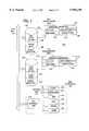
- FIG. 1is a block diagram of a RAID system of the present invention.
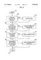
- FIG. 2is a flow diagram of the process that is executed at power on and that produces the various change lists.
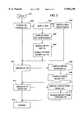
- FIG. 3is a flow diagram of the process that displays drive identification data for drives that are on a change lists, and enables various options for user responses to the various changes.
- FIG. 4is a diagram of an algorithm for logical drive migration
- Table 1is a code table that lists the configuration data that is stored in each of the disk drive units attached to the system, and is also stored in the RAID controller's NVRAM and flash memory.
- Table 2is a code table that lists the system management data that is stored in each of the disk drive units attached to the system, and is also stored in the RAID controller's NVRAM and flash memory.
- the RAID system 100 of the preferred embodimentincludes a Small Computer System Interface ("SCSI") bus 101, although other bus architectures may also be used.
- a disk drive unit 102can be connected to bus 101, but is illustrated in FIG. 1 as being disconnected from the bus.
- Disk drive unit 102includes a well known power reset subsystem 103 that sends a signal out over bus 101 to indicate that a power reset has just occurred.
- the signal that is sent out over the bus in response to a power resetis well known in the art and is commonly called a "unit attention error" signal.
- Disk drive unit 102also includes a well known error or defect detection subsystem 104 that can detect defects in the disk drive unit.
- Configuration data 105is stored in disk drive unit 102, for example, in the last 16 sectors of the disk.
- the configuration datais illustrated in more detail in Table 1, which is a computer code listing of all the data that, collectively, makes up the configuration data.
- the configuration data 105includes operating parameter data 106 that includes information about the state or status of the disk drive unit, as well as other operating parameters.
- the current state of a disk driveis indicated by a 5 bit "state” code, which is found at line 17 of Table 1 and further described in the remarks that follow through line 36.
- state codesThere are 9 state codes that are defined.
- “ONL”indicates that the drive is “on line.”
- “RBL”indicates that information from a failed drive is currently being “rebuilt” onto this drive. A rebuilding process may take place after a drive has failed, and the data that was lost from the failed drive is reconstructed on a drive that has been temporarily marked RBL.
- DDDindicates a “defunct disk drive.”
- Each of these three disk drive states(ONL, RBL and DDD) are referred to as a "hard configured” state, because these states are only used to identify a disk drive that is part of the current system configuration (note, a defunct drive that is marked DDD is still considered to be part of the current system configuration, despite that fact that it has failed).
- the "RDY” stateindicates that a drive is “ready”, which means that the drive is available for use and can be moved into another state, such as the SHS state. Unlike the HSP state, a drive that is in the RDY state usually requires user intervention to move it to another state.
- the "SBY” stateis similar to the RDY state, except that a drive in this state is not spinning.
- the RDY stateis the default state for new hard disk drives that are inserted into the system, while the SBY state is the default state for a new tape or CD ROM drive.
- the operating parametersalso include an indication of the physical location of the drive, such as the "channel number" of line 42 and the "SCSI I.D.” of line 43.
- the channel numberidentifies the particular bus or bank that the drive has been configured for while the SCSI I.D., which may also be referred to as the "Target I.D.”, identifies the particular slot or bay that the drive has been configured for.
- the "EMP" or "empty" stateis not technically a drive state, but indicates that a particular bay is empty, i.e., no drive is installed in that bay.
- the configuration dataincludes product identification and serial number field 107, which is found in line 38 of Table 1.
- the product I.D. and serial number informationis assigned by the manufacturer of the disk drive unit and in many, but not all cases this information is stored at a predetermined address within the disk drive unit.
- the systemtakes the manufacturer's product I.D. and serial number from the predetermined location and copies it into the product I.D. and serial number field of the configuration data.
- a user assigned disk drive unit identification field 108is also part of the configuration data which, in Table 1, is located at line 161. At the time the disk drive units are first configured, the user is given an opportunity to enter a unique identification code for all disk drives. The user may, or may not, choose to assign such an identification code.
- Time stamp field 109is provided for the purpose of uniquely identifying the configuration of a disk drive in the event that the manufacturer either fails to assign the product I.D. and serial number information, or such information is stored at a non-standard address within the disk drive unit and, in addition, the user also fails to assign a unique user defined I.D. in field 108.
- the update count in update count field 110is initially set to one, and incremented each time the configuration data is changed; no matter how small the change. Although incrementing the update count is preferred, any other change to this field would be permissible, such as decrementing the count, as long as a unique update count number is assigned each time the configuration is changed.
- a second disk drive unit 111is illustrated in FIG. 1 as being connected to bus 101.
- Disk drive unit 111is similar to disk drive unit 102, and includes power reset 112 and defect detection 113 subsystems similar to those of disk drive 102.
- Configuration data 114is stored in disk drive 111 and includes operating parameters 115, product I.D. and serial number field 116, user assigned identification field 117, time stamp field 118 and update count field 119 similar to those of disk drive 102.
- Both disk drive units 102 and 111are designed to be "hot swapped" into and out of the RAID system, which means that they can be plugged into and unplugged from bus 101, all without turning the power off.
- poweris picked up by the disk drive unit from the bus, thereby causing a power reset of the disk drive unit which, in turn, causes a power reset signal to be sent from the power reset subsystem (e.g., 103 or 112) out over the bus.
- the power reset subsysteme.g., 103 or 112
- RAID controller 120includes an internal bus 122 that is coupled to SCSI bus 101 via a bus interface unit 121.
- a processor 123, RAM 124 and ROM 125are coupled to internal bus 122.
- a non-volatile memory 126is also coupled to internal bus 122.
- Non-volatile memory 126is preferable of the type commonly referred to as a non-volatile RAM or "NVRAM", which is typically a low power CMOS memory that is powered or backed-up by a battery, such that the information stored in the non-volatile memory will not be lost when the main power is switched off.
- a timer 127is also coupled to internal bus 122 and is used to "time stamp" the configuration data of each of the disk drive units in the system.
- timer 127may use some arbitrary time system in which the timer is simply incremented at some predetermined interval, such as 1.3 msec, which is the time interval used in a preferred embodiment.
- Configuration datais not only stored in NVRAM 126, but also in a well known electrically erasable programmable read only memory (EEPROM) 128, which is also referred to as a "flash" memory.
- EEPROMelectrically erasable programmable read only memory
- flash memory 128, however,is only updated at power on, while any changes to the system configuration during operation are stored in NVRAM 124 and also entered into a "device change list", which is also stored in NVRAM and on each disk drive.
- This device change listis described in more detail below with regards to the description of Table 2 and later, with regards to FIG. 2.
- the elements of RAID controller 120such as processor 123 and timer 127, as well as programs and data loaded into memories 124-126, provide the means for performing the various functions described below.
- this programmable computer subsystemis the preferred implementation for carrying out the functions described below, other embodiments may also be suitable, such as the use of discrete hardwired logic.
- Each disk drive unit in the system(e.g., 102 and 111 ) stores, not only its own configuration data, but also configuration data for each and every disk drive unit in the system.
- each disk drive unithas all the configuration data for the entire system.
- other system management informationis also stored in each disk drive, typically in the last 16 sectors of the disk. This system management information is illustrated in Table 2, which is a code table that illustrates the various types of system management data that is stored in each disk.
- Disk drivesare physically attached to a RAID system by plugging them into open slots or bays, which are arranged in banks. Each bank is referred to as a "channel" and each bay has an associated "target I.D.” As indicated in Table 2, system management information that is indicative of the particular target I.D. and channel that a drive has been configured for is stored in lines 3 and 4, respectively. In line 5, the configuration data, as described in more detail in Table 1, for each of the disk drives in the system is stored. Following the configuration data, a "device change list" is stored, as indicated in line 6. This device change list is described in more detail below with regards to FIG. 2.
- the RAID controller 120executes a power on self test routine ("POST"), which is stored in ROM 125 and which begins at step 201, as illustrated in FIG. 2.
- POSTpower on self test routine
- step 202POST checks for a device change list in NVRAM and if one is found, branches to step 203 wherein flash memory 128 is updated with the latest changes to the configuration data, as recorded in the device change list. If configuration changes are made during system operation, the configuration data in the NVRAM is updated and the change in the configuration data is entered into the device change list.
- configuration datais also stored in flash memory 128, the flash memory is only updated with the latest configuration data after a reset of the RAID controller or at power on (i.e., at step 203).
- the device change listonly includes the difference between the configuration data in the NVRAM and the configuration data in the flash memory.
- the device change listis either deleted or modified in some fashion to indicate that there are no current differences between the configuration data in the NVRAM and the flash memory, such as by resetting all the entries in the device change list to zero.
- RAID controller 120looks for a new drive in a previously empty bay. More specifically, the RAID controller is looking for a target I.D. that is marked "EMP" (empty) in the current configuration and that now has a drive in it. If such a new drive is found, it is entered into a "power on change list" at step 205. The RAID controller also looks for each drive of the current configuration. If the controller is unable to find a drive from the current configuration anywhere in the system, that missing drive is also entered into the power on change list at step 205.
- EMPempty
- the RAID controlleralso looks for each drive of the current configuration. If the controller is unable to find a drive from the current configuration anywhere in the system, that missing drive is also entered into the power on change list at step 205.
- RAID controller 120determines if each hard configured drive of the current configuration is in its proper location (target I.D. and channel). If not, a "wrong I.D.” list is created in step 207. And in next step 208, the controller looks for any drives that are not part of the current configuration and that are in hard configured locations; i.e., at target I.D.'s that are marked ONL or RBL in the current configuration. If such an unidentified drive is found, it is entered into an "unidentified drive" list in step 209.
- RAID controller BIOSwill execute the routine of FIG. 3, which begins at step 301.
- the controllerlooks for a power on change list and, if one is found, branches to step 303.
- the controllerlooks for new drives in previously empty bays. In other words, bays that are marked "EMP" in the current configuration, but now have a drive marked "RDY” or "SBY.” If such a dive is found, its identity is displayed to the user in step 304. More specifically, the old state, new state, channel and bay are displayed.
- the routinerepeats steps 302, 303 and 304 until all such new drives have been displayed in step 304.
- step 303the program branches at step 303 to step 305 wherein the identity of the non-responding drive is displayed to the user. More specifically, the old state, new state, channel and bay are displayed, wherein the old state is the configured state, and the new state is the state that the controller will assign to the drive.
- the "F4" function keyis enabled, which is a "retry" option. When F4 is enabled, it gives the user an opportunity to correct the problem and then select the F4 retry key. For example, a drive may not be responding simple because the user failed to insert the drive in the system.
- the usermay elect to insert the proper drive into the system and then select the retry key.
- the "F5" keyis also enabled, which instructs the system to assign the new state, which is displayed on the screen, to the drive.
- the programrepeats steps 302, 303, 305 and 306 until all non-responding drives have been displayed.
- next step 307the controller checks for a wrong I.D. list, which indicates that a previously configured drive has been found, but in the wrong location. If such a drive is found, the program branches to step 308 wherein the identity of the drive is displayed. More specifically, the old channel and old bay are displayed, followed by the new channel and new bay location.
- step 309the F6 key is enabled. The F6 key gives the user the option to adjust the configuration. In other words, the configuration data will be adjusted to reflect the new locations of the previously configured drives. In the alternative, the user may elect to physically relocate the drives, and then select the retry key. Steps 307, 308 and 309 are repeated until all "wrong I.D.” drives have been displayed.
- step 310the program branches to step 311 if an unidentified drive list is found.
- step 311the identity of the unidentified drive is displayed. More specifically, the host I.D., old channel and old bay are displayed, followed by the new channel and new bay.
- the host I.D., old channel and old bayare from the drive (not from the NVRAM of the current controller 120), such that it identifies to the user the host I.D., channel and bay that the drive was previously configured for. In most cases, the host I.D., old channel and old bay will identify the system that the drive was previously installed in.
- the new channel and new bayare the channel and bay that the "unidentified" drive is currently installed in.
- the F7 keyis enabled. In the alternative, selecting the F7 key causes the system to import the configuration from the unidentified drives and to update the configuration controller 120. This choice is useful when the controller has been replaced, or when another system has failed and the disks from the failed system are moved to functional system.
- the usermay configure the system at setup time such that, when one or more function keys are enabled, the system will select one of the enabled functions automatically, thereby removing the need to press a function key.
- This mode of operationis useful when the system is in a remote location and not readily accessible to the user.
- the function having the corresponding highest numbered function keywill be automatically selected. For example, if all function keys are enabled, the function corresponding to the F7 key will be selected. If only the F6, F5 and F4 keys are enabled, then the function corresponding to the F6 key will be selected. If only the F4 key is enabled, however, no function will be automatically selected. Since the purpose of the F4 key is to allow the user to physically reconfigure the system, and physical reconfiguration can only be accomplished by the user, only the user can activate the function corresponding to the F4 key.
- LDMlogical drive migration
- datacould be migrated (add/remove physical disk devices) or the existing RAID level of a logical drive (array) could be changed to provide better fault tolerance for the data.
- This inventionallows a user to change the RAID level of an existing logical drive, or to migrate logical drive data by simply issuing an LDM command to the adapter, which then provides a redefined logical drive configuration structure.
- Logical drive configuration structure informationconsists of data such as RAID level, state, number of chunks (areas of disk space), number of sectors of data available to a user, and details of each chunk specifying the disk's SCSI address, starting sector and number of sectors allocated to a logical drive.
- This inventionalso permits a user to migrate logical drive data belonging to one RAID level to another RAID level.
- the primary objective of this functionis to provide a mechanism for changing RAID levels. It also allows, with some restrictions, shrinkage and expansion of the logical drive size.
- the LDM algorithmimposes the following restrictions:
- Start Logical Block Address (LBA) of the first chunk (chunk 0) of the destination logical drivemust not be greater than the start LBA of the first chunk of the source logical drive that is to be migrated.
- the stripe unit size of the source and destination logical drivesmust be the same.
- the logical drive migration algorithmexamines the number of source devices, the number of destination devices, the RAID level change requested and the associated stripe unit size to determine the start block, end block, and direction in which to migrate logical drive data.
- the algorithmdecides whether Top Down (TD), Bottom UP (BU) or combinations of TD and BU are to be used as the direction in which data must be migrated to preserve data integrity.
- TDTop Down
- BUBottom UP
- start block and end blockdefining the LBA address, have a different meaning depending on the direction(s) of migration. For example, the start block for the BU direction defines the beginning LBA address of the last block, while start block for the TD direction defines the beginning LBA address of the first block of data.
- DIRdirection (TD, BU)
- NCSnumber of chunks in source
- NCDnumber of chunks in destination
- each physical driveis made up of “stripe units” and these stripe units are combined across the physical drives to create a stripe of data.
- Each stripe of dataalso contains a parity stripe unit to allow reconstruction of data if a single drive failure occurs. Using this parity stripe unit, any stripe unit within the stripe can be reconstructed if a physical drive fails.
- a logical driveis made up of multiple stripes and a stripe is made up of multiple stripe units wherein each stripe unit is located on a unique physical drive.
- Media errors on a physical drivecan occur that result in the device not being able to supply the requested data for a stripe unit. If a media error occurs during a logical drive rebuild, then the data on the stripe cannot be reconstructed. For example, if a media error occurred while reading a stripe unit on a first disk, then the corresponding (from the same stripe) stripe unit from the second disk could not be reconstructed. If this error is ignored, the next time the user accesses data in the stripe unit of the second disk, incorrect data will be supplied since it was not reconstructed correctly.
- RAID controllersreport the device with the media errors as a dead device. When this occurs, the entire logical drive will go off line since the data can no longer be reconstructed (at this point there are 2 stripe units with unknown data). When a logical drive is off line, the user cannot access any data on that logical drive and all data on that logical drive is considered to have been lost. To bring the logical drive back online, the user must replace the device that has the media error, and restore the lost data.
- this inventionuses a table located in the adapter's NVRAM to keep track of stripes that could not be reconstructed successfully. If a stripe could not be reconstructed successfully during a logical drive rebuild operation, an entry is made in a "bad stripe table" containing the logical drive and the stripe number that could not be rebuilt successfully. When the user tries to access data, this table is checked. If there is an entry in the bad stripe table for a stripe being accessed, the user will receive an error message. Although the user may lose a small portion of the data, the user is only presented with an error message instead of incorrect data.
- a disk formatting utilitywill also receive an error when accessing the portion of the disk in the bad stripe table. When this occurs, the formatting utility will reassign the failing area to another area on the logical drive.
- the bad stripe tablecan also be checked on write operations. If an entire stripe of data is written successfully and that stripe is found in the bad stripe table, the entry is removed. To write the entire stripe, sectors that have non-recoverable media errors need to be reassigned by the disk drive or Raid adapter.
- This inventioncan be further enhanced to only keep track of the stripe unit that could not be rebuilt, or by determining which sector (a smaller portion of disk space than a stripe unit) is bad.
- the bad sectoris determined, only that sector is placed in the bad stripe table instead of the stripe unit or stripe number.
- the failing sectorcan be determined by doing single sector reads to the entire stripe unit or stripe number that is failing. If a sector read fails, then only that sector is placed in the bad stripe table. If a single sector write is done successfully to a sector that is contained in the bad stripe table, then the entry is removed from the table. To write a single sector, sectors that have non-recoverable media errors need to be reassigned by the disk drive or RAID Adapter.
- the bad stripe tableshould also be stored on the physical drives attached to the controller. Each time an entry is made in the NVRAM bad stripe table, the bad stripe table is copied to a reserved area in each physical drive. If the physical drives are moved to another controller, the bad stripe table is copied from the physical drives reserved area to the new controller's NVRAM bad stripe table so that this information is not lost.
- the bad stripe tablecan be split into multiple tables for each logical or physical device. Also, each entry can be maintained in order and searched using a binary search algorithm.
Landscapes
- Engineering & Computer Science (AREA)
- Theoretical Computer Science (AREA)
- General Engineering & Computer Science (AREA)
- Physics & Mathematics (AREA)
- General Physics & Mathematics (AREA)
- Computer Hardware Design (AREA)
- Quality & Reliability (AREA)
- Information Retrieval, Db Structures And Fs Structures Therefor (AREA)
Abstract
Description
TABLE 1 __________________________________________________________________________#define NCHNS 3 // Comments with // ro/wi is read only write ignore field // r/w is read write field // ro is read only field // =========================================================== typedef struct // 36-byte SCSI device state UCHAR ucInitiator; // Initiator = 1, Target = 0, ro/wi UCHAR ucParameters; // Bits 0-4 device type: matches, ro/wi // Inquiry cmd: 0 = Disk, 1 = Tape, etc. // Bit 5 : 0 = 5 MHZ, 1 = Fast Scsi // Bit 6 : 0 = 8 bit, 1 = 16 bit // Bit 7 : 0 = no tag que, 1 = tag que UCHAR ucMiscFlag; //Bit 0 = PFA, ro/wi //Bit 1 = Stale data UCHAR ucState; // 00 = EMP, 04 = DHS, 08 = DDD, 01 = SBY, r/w // 81H = RDY, 85H = HSP, 89H = ONL, 8BH = RBL // 05 = SHS // Bit 7 = Spin, // Bit 3 = Configured, //Bit 2 = HotSpare, //Bit 1 = Rebuild in progress, //Bit 0 = Present: true if device can // pass SCSI Test Unit Ready command. // Bit 7 3 2 1 0 State // SPN CFG HSP RBL TUR // 1 1 0 0 1 ONL // 1 0 1 0 1 HSP // 1 0 0 0 1 RDY // 1 1 0 1 1 RBL // 0 1 0 0 0 DDD // 0 0 1 0 0 DHS // 0 0 0 0 1 SBY // 0 0 1 0 1 SHS // 0 0 0 0 0 EMP ULONG ulBlockCount; // Total # sectors not inc reserved, ro/wi UCHAR ucDeviceID 28!; // Inquiry product id & serial number, ro/wi } DEVSTATE; typedef struct { UCHAR ucChn; // Channel number: 0 - NCHNS-1, r/w UCHAR ucTgt; // SCSI id R←: 0 - MAX.sub.-- TGT-1, r/w USHORT usMisc; // set to zero except inCHUNK 0!,CHUNK 1! and //CHUNK 2!. // CHUNK 3! is in each logical drive is reserved for // client server admin. // InCHUNK 0! andCHUNK 1! it is as follows // bits 1 0:00 ch 0, Io id => bank 0 // 01 ch 0, lo id => bank 1 // 10 ch 0, Io id => bank 2 // bits 3 2:00 ch 0, hi id => bank 0 // 01 ch 0, hi id => bank 1 // 10 ch 0, hi id => bank 2 // bits 5 4:00 ch 1, lo id => bank 0 // 01 ch 1, lo id => bank 1 // 10 ch 1, lo id => bank 2 // bits 7 6:00 ch 1, hi id => bank 0 // 01 ch 1, hi id => bank 1 // 10 ch 1, hi id => bank 2 // bits 9 8:00 ch 2, lo id => bank 0 // 01 ch 2, lo id => bank 1 // 10 ch 2, lo id => bank 2 // bits b a:00 ch2, hi id => bank 0 // 01 ch 2, hi id => bank 1 // 10 ch 2, hi id => bank 2 // bits d c:00 ch 3, lo id => bank 0 // 01 ch 3, lo id => bank 1 // 10 ch 3, lo id => bank 2 // bits f e:00 ch 3, hi id => bank 0 // 01 ch 3, hi id => bank 1 // 10 ch 3, hi id => bank 2 // Adapter does not process these bits. // it is user defined ULONG ulStartSect; // Start sector for this logical drive, r/w ULONG ulNoOfSects, // No. of sectors allocated to this log drv, r/w } CHUNK; typedef struct { USHORT usUserField; // User defined, r/w UCHAR ucState; // Current status of logical drive = r/w // 03H - OKaY // 04H - CRiTical // 02H - OFfLine // 00h - FREe // 05H - LDM // 06H - SYS // 24H - CRS (Critical SYS) // 14H - CRM (Critical LDM) UCHAR ucRaidCacheParam; // bits 2-0 - Raid level (0,1,5) r/w // bit 3-6 - 0 // bit 7 -1 => Write-Back // 0 => Write-Through UCHAR ucNoOfChunkUnits; // No. of chunk units inparity band 1 to 16, r/w UCHAR ucStripeSize; // 0 - 3 reserved for future expansion, r/w // 4 = 8k stripe unit // 5 = 16K stripe unit // 6 = 32K stripe unit // 7 = 64K stripe unit // 8 + reserved for future // NOTE: RAID Adapter RF supports 8K to 64K stripe. UCHAR ucParams; // bit 0 - 0, reserved // bit 2 - 0 data scrubbing is enabled // 1 data scrubbing is disabled // bit 3 - cache bypass on read, ro // bit 4 - 0 copy of write data also in Posiedon, r/w // 1 dual copy disabled // bit 5 - 0 read-ahead enabled, r/w // 1 read-ahead disabled // bit 6 - 0 Reserved //bits 1 and 7 = 0 reserved for future UCHAR ucReserved; // used by the configurator ULONG ulLogDrvSize; // size of the logical drive, ro CHUNK chunk MAX.sub.-- CHUNKS!; // details of each chunk unit } LOGICALDRIVE; typedef struct { UCHAR board.sub.-- disc 8!; // board description in ascii. For RAID Adapter RF ro // this field is `CPH RF3C` UCHAR processor 8!; // local processor description in ascii. ro // For RAID Adapter RF this field is `403GC-33` UCHAR ucNoChanType; // bits 0-3 - number of l/O (SCSI) channels, ro // bits 4-6 - channel type, ro // 000 parallel SCSI wide // note: RAID Adapter RF only // supports parallel wide SCSI // 001 parallel SCSI narrow // 010 serial SSA // 011 serial P1394 // 100 serial FC-AL // bit 7 - 0 reserved for future UCHAR ucNoHostIntType; // number and type of host interface, ro // bits 0-3 - number of host interface // bits 4-6 - interface type // 000 32 bit PCI // 001 64 bit PCI // 010 80 MB/sec Micro Channel // 011 40 MB/sec Micro Channel // 101 EISA // bit 7 - 0 reserved for future UCHAR ucCompression; // type of compression hardware, 0 for none, ro UCHAR ucNvramType; // NVRAM cache type, 0 for no cache nvram, ro // 1 for Posiedon, ro ULONG ulNvramSize; // size of nvram in sectors when present, ro } HARDWAREDISC; typedef struct { UCHAR ucNoOfLogDrives; // No. of logical drives: 1 - 8, r/w UCHAR ucDateD; // date of configuration written, r/w UCHAR ucDateM; // date of configuration written, r/w UCHAR ucDateY; // date of configuration written, r/w // packed ddmmyy UCHAR init.sub.-- id 4 !; // Initiator Id // bits 0-4 // Speed bits 5-7 // 000x xxxx - 10MHZ // 001x xxxx - 20MHZ // 010x xxxx - 5MHZ // 111x xxxx - 0MHZ UCHAR host.sub.-- id 12 !; // Chassis # from host, r/w UCHAR time.sub.-- sign 8 !; // Time stamp from RAID Adapter RF clock, ro struct { UINT cfgdrv.sub.-- updcnt 16; // count of cfgupdate since write cfg UINT startup.sub.-- delay :4; // delay (sec) between spinup groups UINT concur.sub.-- drvstart :4; // # of drives to spinup in parallel UINT reserved :3; // reserved UINT stage :1; // 1 = stage data during migration UINT cluster :1; // 1 = adapter is part of a cluster UINT bios.sub.-- compat :1; // 1 = compatibility, 0 = extended UINT boot.sub.-- cdr :1; // 1 = boot from CDROM, 0 = from drive UINT auto.sub.-- rearrange :1; // 1 = auto rearrange, 0 = just list }UserOpt; USHORT user.sub.-- field; // User defined UCHAR ucRebuildRate; // Rebuild Rate, r/w // 01h = low, 08h = mid, 0Fh = high UCHAR ucReserve; // set to zero } CONFHDR; typedef struct { CONFHDR configheader; // configuration header HARDWAREDISC hardware.sub.-- disc; // hardware description LOGICALDRIVE logical.sub.-- drive MAX.sub.-- LOG.sub.-- DRVS // describing each logical // drv DEVSTATE dev NCHNS ! MAX.sub.-- TGT + 1 !; // Info about device at // each adr } CONFIGURATION; __________________________________________________________________________
TABLE 2 ______________________________________ UCHAR ucRepTblCnt; // Number of entries in ReplacementTb1 UCHAR ucDevChgCnt; UCHAR tgt; //SCSI Target ID UCHAR chn; //SCSI Channel CONFIGURATION cfg; // Full copy of configuration struct DEVCHGLST DeviceChangeList MAX.sub.-- DEV.sub.-- CHG.sub.-- LST !; RTENTRY ReplacementTbl MAX.sub.-- LOG.sub.-- DRVS !; ______________________________________
Claims (5)
Priority Applications (4)
| Application Number | Priority Date | Filing Date | Title |
|---|---|---|---|
| US08/887,391US5950230A (en) | 1997-05-28 | 1997-07-02 | RAID array configuration synchronization at power on |
| US09/049,167US6058455A (en) | 1997-07-02 | 1998-03-27 | RAID system having a selectable unattended mode of operation with conditional and hierarchical automatic re-configuration |
| US09/102,261US6282670B1 (en) | 1997-07-02 | 1998-06-22 | Managing defective media in a RAID system |
| US09/179,150US6282619B1 (en) | 1997-07-02 | 1998-10-26 | Logical drive migration for a raid adapter |
Applications Claiming Priority (2)
| Application Number | Priority Date | Filing Date | Title |
|---|---|---|---|
| US86453097A | 1997-05-28 | 1997-05-28 | |
| US08/887,391US5950230A (en) | 1997-05-28 | 1997-07-02 | RAID array configuration synchronization at power on |
Related Parent Applications (1)
| Application Number | Title | Priority Date | Filing Date |
|---|---|---|---|
| US86453097AContinuation-In-Part | 1997-05-28 | 1997-05-28 |
Related Child Applications (3)
| Application Number | Title | Priority Date | Filing Date |
|---|---|---|---|
| US09/049,167DivisionUS6058455A (en) | 1997-07-02 | 1998-03-27 | RAID system having a selectable unattended mode of operation with conditional and hierarchical automatic re-configuration |
| US09/102,261DivisionUS6282670B1 (en) | 1997-07-02 | 1998-06-22 | Managing defective media in a RAID system |
| US09/179,150DivisionUS6282619B1 (en) | 1997-07-02 | 1998-10-26 | Logical drive migration for a raid adapter |
Publications (1)
| Publication Number | Publication Date |
|---|---|
| US5950230Atrue US5950230A (en) | 1999-09-07 |
Family
ID=25343474
Family Applications (1)
| Application Number | Title | Priority Date | Filing Date |
|---|---|---|---|
| US08/887,391Expired - LifetimeUS5950230A (en) | 1997-05-28 | 1997-07-02 | RAID array configuration synchronization at power on |
Country Status (1)
| Country | Link |
|---|---|
| US (1) | US5950230A (en) |
Cited By (60)
| Publication number | Priority date | Publication date | Assignee | Title |
|---|---|---|---|---|
| US6098119A (en)* | 1998-01-21 | 2000-08-01 | Mylex Corporation | Apparatus and method that automatically scans for and configures previously non-configured disk drives in accordance with a particular raid level based on the needed raid level |
| US6223300B1 (en)* | 1997-11-21 | 2001-04-24 | Alps Electric Co., Ltd. | Disk array apparatus |
| US6363457B1 (en)* | 1999-02-08 | 2002-03-26 | International Business Machines Corporation | Method and system for non-disruptive addition and deletion of logical devices |
| US20020156951A1 (en)* | 2001-04-18 | 2002-10-24 | International Business Machines Corporation | Method to validate system configuration |
| US20030005120A1 (en)* | 2001-06-28 | 2003-01-02 | Madhav Mutalik | Information replication system having enhanced error detection and recovery |
| US6549978B2 (en) | 2001-01-17 | 2003-04-15 | International Business Machines Corporation | Method for storage controllers with different data formats to access common storage configuration information |
| US20030182494A1 (en)* | 2002-03-20 | 2003-09-25 | Rodrigues Steven Harold | Raid assimilation method and apparatus |
| US20030191840A1 (en)* | 2002-04-08 | 2003-10-09 | Maciel Frederico Buchholz | Shared storage device and method for updating contents of the same |
| US6643735B2 (en) | 2001-12-03 | 2003-11-04 | International Business Machines Corporation | Integrated RAID system with the capability of selecting between software and hardware RAID |
| US20030212857A1 (en)* | 2002-05-09 | 2003-11-13 | International Business Machines Corporation | Adaptive startup policy for accelerating multi-disk array spin-up |
| US6725331B1 (en)* | 1998-01-07 | 2004-04-20 | Emc Corporation | Method and apparatus for managing the dynamic assignment resources in a data storage system |
| US6732231B1 (en)* | 2001-02-28 | 2004-05-04 | Emc Corporation | System and method for management of mirrored storage devices storing device serial numbers |
| US20040117551A1 (en)* | 2002-12-12 | 2004-06-17 | Jerry Wang | Array configuration for multiple disk-array system |
| US20040117550A1 (en)* | 2002-12-12 | 2004-06-17 | Jerry Wang | Disk administrating system for multiple disk-arrays |
| US20040125812A1 (en)* | 2002-12-25 | 2004-07-01 | Meng-Hua Kao | Adapter for internetworking wwan and wlan |
| US20040133742A1 (en)* | 2003-01-07 | 2004-07-08 | Dell Products L.P. | System and method for raid configuration |
| US20040158763A1 (en)* | 2002-12-12 | 2004-08-12 | Jerry Wang | Testing method of array configuration for multiple disk-array system |
| US6792486B1 (en) | 2002-04-30 | 2004-09-14 | Western Digital Ventures, Inc. | System and method for managing information storage among plural disk drives |
| US20050076260A1 (en)* | 2003-10-07 | 2005-04-07 | Ching-Hai Hung | Raid consistency initialization method |
| US6978282B1 (en) | 2001-09-04 | 2005-12-20 | Emc Corporation | Information replication system having automated replication storage |
| US6983335B2 (en)* | 2002-12-12 | 2006-01-03 | Via Technologies, Inc. | Disk drive managing method for multiple disk-array system |
| US7003692B1 (en)* | 2002-05-24 | 2006-02-21 | Cisco Technology, Inc. | Dynamic configuration synchronization in support of a “hot” standby stateful switchover |
| US20060059408A1 (en)* | 2004-09-10 | 2006-03-16 | Takashi Chikusa | Disk array system |
| US20060107103A1 (en)* | 2004-11-01 | 2006-05-18 | Steven Rodrigues | Apparatus and method for recovering destroyed data volumes |
| US7080133B1 (en)* | 2000-07-17 | 2006-07-18 | International Business Machines Corporation | Method and system for configuring a computer network |
| US20060168358A1 (en)* | 2005-01-25 | 2006-07-27 | Sunplus Technology Co., Ltd. | Storage control system |
| US7107395B1 (en) | 1998-12-31 | 2006-09-12 | Emc Corporation | Apparatus and methods for operating a computer storage system |
| US20060218413A1 (en)* | 2005-03-22 | 2006-09-28 | International Business Machines Corporation | Method of introducing physical device security for digitally encoded data |
| US20060259816A1 (en)* | 2005-05-10 | 2006-11-16 | Spectra Logic Corporation | Data integrity analysis for a data storage system |
| US20060294281A1 (en)* | 2005-06-27 | 2006-12-28 | Fujitsu Limited | Storage device and method of connecting storage device to host computer suitable for both power-on time and hot plug time |
| US20070174685A1 (en)* | 2006-01-19 | 2007-07-26 | Banks Donald E | Method of ensuring consistent configuration between processors running different versions of software |
| US20070226370A1 (en)* | 2006-03-27 | 2007-09-27 | Cisco Technology, Inc. (A California Corporation) | Method and apparatus for managing foreign-owned fields in versioned messages |
| US20070294582A1 (en)* | 2006-05-05 | 2007-12-20 | Dell Products L.P. | Reporting software RAID configuration to system BIOS |
| US20070294476A1 (en)* | 2006-06-16 | 2007-12-20 | Corn Vance E | Method For Representing Foreign RAID Configurations |
| EP1158407A3 (en)* | 2000-05-25 | 2008-01-30 | Hitachi, Ltd. | Disk array system |
| US20080115008A1 (en)* | 2006-11-13 | 2008-05-15 | Daftardar Jayant M | Systems and methods for recovering from configuration data mismatches in a clustered environment |
| US20080120461A1 (en)* | 2006-11-21 | 2008-05-22 | Accusys. Inc. | Method for maintaining disk array management information |
| US20080183975A1 (en)* | 2005-09-30 | 2008-07-31 | Lynn Foster | Rebuilding data on a dispersed storage network |
| US20090049291A1 (en)* | 2007-08-13 | 2009-02-19 | Linda Van Patten Benhase | Consistent data storage subsystem configuration replication in accordance with sequence information |
| US20090210619A1 (en)* | 2008-02-19 | 2009-08-20 | Atul Mukker | Method for handling more than a maximum number of supported drives in a raid configuration |
| US7657823B1 (en) | 2006-04-17 | 2010-02-02 | Marvell International Ltd. | Efficient RAID ECC controller for RAID systems |
| US20100037091A1 (en)* | 2008-08-06 | 2010-02-11 | Anant Baderdinni | Logical drive bad block management of redundant array of independent disks |
| US20100088440A1 (en)* | 2008-10-03 | 2010-04-08 | Donald E Banks | Detecting and preventing the split-brain condition in redundant processing units |
| US20100321811A1 (en)* | 2009-06-19 | 2010-12-23 | Spectra Logic Corporation | Drive life cycle management |
| US20110066881A1 (en)* | 2009-09-14 | 2011-03-17 | International Business Machines Corporation | Resilient software-controlled redundant array of independent disks (raid) |
| US8131919B1 (en)* | 2007-12-21 | 2012-03-06 | Emc Corporation | Techniques for controlling storage device use by performing a storage device location assessment operation based on a current storage device identifier |
| US20120254535A1 (en)* | 2010-12-13 | 2012-10-04 | International Business Machines Corporation | Instant data restoration |
| US20140019685A1 (en)* | 2011-08-08 | 2014-01-16 | Huawei Technologies Co., Ltd | Method and Apparatus for Processing RAID Configuration Information and RAID Controller |
| US20140115309A1 (en)* | 2012-10-18 | 2014-04-24 | International Business Machines Corporation | Validation of storage arrays based on information stored in global metadata |
| US8767330B2 (en) | 2003-06-26 | 2014-07-01 | Spectra Logic, Corp. | Tape cartridge auxiliary memory based library |
| US20150331926A1 (en)* | 2011-12-02 | 2015-11-19 | Canon Kabushiki Kaisha | Information processing apparatus, control method therefor and storage medium |
| US9244621B2 (en) | 2012-10-18 | 2016-01-26 | International Business Machines Corporation | Global data establishment for storage arrays controlled by a plurality of nodes |
| CN105760255A (en)* | 2016-02-14 | 2016-07-13 | 北京艾森思科技有限公司 | RAID card configuration information backup and recovery method and device |
| US9495105B2 (en)* | 2005-09-01 | 2016-11-15 | Hitachi, Ltd. | System managing a plurality of flash memory devices |
| US9665292B2 (en)* | 2015-01-08 | 2017-05-30 | Dell Products, Lp | System and method for providing consistent metadata for RAID solutions |
| US9934076B2 (en) | 2012-12-14 | 2018-04-03 | Vmware, Inc. | Systems and methods for finding solutions in distributed load balancing |
| US10306005B1 (en)* | 2015-09-30 | 2019-05-28 | EMC IP Holding Company LLC | Data retrieval system and method |
| US11038750B2 (en)* | 2019-10-23 | 2021-06-15 | Toshiba Global Commerce Solutions Holdings Corporation | Management of configuration modifications in distributed data systems |
| CN115022175A (en)* | 2022-06-21 | 2022-09-06 | 工银科技有限公司 | Configuration information synchronization method and device |
| WO2025144672A1 (en)* | 2023-12-20 | 2025-07-03 | Computero Inc. | Data backup device |
Citations (2)
| Publication number | Priority date | Publication date | Assignee | Title |
|---|---|---|---|---|
| US5237689A (en)* | 1990-05-31 | 1993-08-17 | Hewlett-Packard Company | Configuration of mass storage devices |
| US5440716A (en)* | 1989-11-03 | 1995-08-08 | Compaq Computer Corp. | Method for developing physical disk drive specific commands from logical disk access commands for use in a disk array |
- 1997
- 1997-07-02USUS08/887,391patent/US5950230A/ennot_activeExpired - Lifetime
Patent Citations (2)
| Publication number | Priority date | Publication date | Assignee | Title |
|---|---|---|---|---|
| US5440716A (en)* | 1989-11-03 | 1995-08-08 | Compaq Computer Corp. | Method for developing physical disk drive specific commands from logical disk access commands for use in a disk array |
| US5237689A (en)* | 1990-05-31 | 1993-08-17 | Hewlett-Packard Company | Configuration of mass storage devices |
Cited By (97)
| Publication number | Priority date | Publication date | Assignee | Title |
|---|---|---|---|---|
| US6223300B1 (en)* | 1997-11-21 | 2001-04-24 | Alps Electric Co., Ltd. | Disk array apparatus |
| US6845428B1 (en) | 1998-01-07 | 2005-01-18 | Emc Corporation | Method and apparatus for managing the dynamic assignment of resources in a data storage system |
| US6725331B1 (en)* | 1998-01-07 | 2004-04-20 | Emc Corporation | Method and apparatus for managing the dynamic assignment resources in a data storage system |
| US6098119A (en)* | 1998-01-21 | 2000-08-01 | Mylex Corporation | Apparatus and method that automatically scans for and configures previously non-configured disk drives in accordance with a particular raid level based on the needed raid level |
| US7107395B1 (en) | 1998-12-31 | 2006-09-12 | Emc Corporation | Apparatus and methods for operating a computer storage system |
| US6363457B1 (en)* | 1999-02-08 | 2002-03-26 | International Business Machines Corporation | Method and system for non-disruptive addition and deletion of logical devices |
| EP1158407A3 (en)* | 2000-05-25 | 2008-01-30 | Hitachi, Ltd. | Disk array system |
| US7080133B1 (en)* | 2000-07-17 | 2006-07-18 | International Business Machines Corporation | Method and system for configuring a computer network |
| US6549978B2 (en) | 2001-01-17 | 2003-04-15 | International Business Machines Corporation | Method for storage controllers with different data formats to access common storage configuration information |
| US6732231B1 (en)* | 2001-02-28 | 2004-05-04 | Emc Corporation | System and method for management of mirrored storage devices storing device serial numbers |
| US20020156951A1 (en)* | 2001-04-18 | 2002-10-24 | International Business Machines Corporation | Method to validate system configuration |
| US6854052B2 (en)* | 2001-04-18 | 2005-02-08 | International Business Machines Corporation | Method to validate system configuration |
| US20030172158A1 (en)* | 2001-06-28 | 2003-09-11 | Pillai Ananthan K. | Information replication system mounting partial database replications |
| US20060200698A1 (en)* | 2001-06-28 | 2006-09-07 | Pillai Ananthan K | Information replication system mounting partial database replications |
| US7096250B2 (en) | 2001-06-28 | 2006-08-22 | Emc Corporation | Information replication system having enhanced error detection and recovery |
| US7076685B2 (en) | 2001-06-28 | 2006-07-11 | Emc Corporation | Information replication system mounting partial database replications |
| US20030005120A1 (en)* | 2001-06-28 | 2003-01-02 | Madhav Mutalik | Information replication system having enhanced error detection and recovery |
| US6978282B1 (en) | 2001-09-04 | 2005-12-20 | Emc Corporation | Information replication system having automated replication storage |
| US6643735B2 (en) | 2001-12-03 | 2003-11-04 | International Business Machines Corporation | Integrated RAID system with the capability of selecting between software and hardware RAID |
| US7133964B2 (en)* | 2002-03-20 | 2006-11-07 | Network Appliance, Inc | Raid assimilation method and apparatus |
| US20030182494A1 (en)* | 2002-03-20 | 2003-09-25 | Rodrigues Steven Harold | Raid assimilation method and apparatus |
| US7143256B2 (en)* | 2002-04-08 | 2006-11-28 | Hitachi, Ltd. | Shared storage device and method for updating contents of the same |
| US20030191840A1 (en)* | 2002-04-08 | 2003-10-09 | Maciel Frederico Buchholz | Shared storage device and method for updating contents of the same |
| US6792486B1 (en) | 2002-04-30 | 2004-09-14 | Western Digital Ventures, Inc. | System and method for managing information storage among plural disk drives |
| US20030212857A1 (en)* | 2002-05-09 | 2003-11-13 | International Business Machines Corporation | Adaptive startup policy for accelerating multi-disk array spin-up |
| US6966006B2 (en) | 2002-05-09 | 2005-11-15 | International Business Machines Corporation | Adaptive startup policy for accelerating multi-disk array spin-up |
| US7003692B1 (en)* | 2002-05-24 | 2006-02-21 | Cisco Technology, Inc. | Dynamic configuration synchronization in support of a “hot” standby stateful switchover |
| US6983335B2 (en)* | 2002-12-12 | 2006-01-03 | Via Technologies, Inc. | Disk drive managing method for multiple disk-array system |
| US7010625B2 (en)* | 2002-12-12 | 2006-03-07 | Via Technologies, Inc. | Disk administrating system for multiple disk-arrays |
| US6985971B2 (en)* | 2002-12-12 | 2006-01-10 | Via Technologies Inc. | Testing method of array configuration for multiple disk-array system |
| US6996637B2 (en)* | 2002-12-12 | 2006-02-07 | Via Technologies, Inc. | Array configuration for multiple disk-array system |
| US20040158763A1 (en)* | 2002-12-12 | 2004-08-12 | Jerry Wang | Testing method of array configuration for multiple disk-array system |
| US20040117550A1 (en)* | 2002-12-12 | 2004-06-17 | Jerry Wang | Disk administrating system for multiple disk-arrays |
| US20040117551A1 (en)* | 2002-12-12 | 2004-06-17 | Jerry Wang | Array configuration for multiple disk-array system |
| US20040125812A1 (en)* | 2002-12-25 | 2004-07-01 | Meng-Hua Kao | Adapter for internetworking wwan and wlan |
| US20040133742A1 (en)* | 2003-01-07 | 2004-07-08 | Dell Products L.P. | System and method for raid configuration |
| US7263582B2 (en)* | 2003-01-07 | 2007-08-28 | Dell Products L.P. | System and method for raid configuration |
| US8767330B2 (en) | 2003-06-26 | 2014-07-01 | Spectra Logic, Corp. | Tape cartridge auxiliary memory based library |
| US10114699B2 (en)* | 2003-10-07 | 2018-10-30 | Infortrend Technology, Inc. | RAID consistency initialization method |
| US20050076260A1 (en)* | 2003-10-07 | 2005-04-07 | Ching-Hai Hung | Raid consistency initialization method |
| US7328392B2 (en)* | 2004-09-10 | 2008-02-05 | Hitachi, Ltd. | Disk array system |
| US20060059408A1 (en)* | 2004-09-10 | 2006-03-16 | Takashi Chikusa | Disk array system |
| US7487385B2 (en) | 2004-11-01 | 2009-02-03 | Netapp, Inc. | Apparatus and method for recovering destroyed data volumes |
| US20060107103A1 (en)* | 2004-11-01 | 2006-05-18 | Steven Rodrigues | Apparatus and method for recovering destroyed data volumes |
| US20060168358A1 (en)* | 2005-01-25 | 2006-07-27 | Sunplus Technology Co., Ltd. | Storage control system |
| WO2006100205A3 (en)* | 2005-03-22 | 2007-01-25 | Ibm | Method and system of introducing physical device security for digitally encoded data |
| US20060218413A1 (en)* | 2005-03-22 | 2006-09-28 | International Business Machines Corporation | Method of introducing physical device security for digitally encoded data |
| US20060259816A1 (en)* | 2005-05-10 | 2006-11-16 | Spectra Logic Corporation | Data integrity analysis for a data storage system |
| US7512838B2 (en)* | 2005-05-10 | 2009-03-31 | Spectra Logic Corporation | Data integrity analysis for a data storage system |
| US20060294281A1 (en)* | 2005-06-27 | 2006-12-28 | Fujitsu Limited | Storage device and method of connecting storage device to host computer suitable for both power-on time and hot plug time |
| US7346721B2 (en)* | 2005-06-27 | 2008-03-18 | Fujitsu Limited | Method and device for connecting a storage device with a plurality of controllers to a host computer during power-on time or hot plug time |
| US9495105B2 (en)* | 2005-09-01 | 2016-11-15 | Hitachi, Ltd. | System managing a plurality of flash memory devices |
| US20080183975A1 (en)* | 2005-09-30 | 2008-07-31 | Lynn Foster | Rebuilding data on a dispersed storage network |
| US8880799B2 (en)* | 2005-09-30 | 2014-11-04 | Cleversafe, Inc. | Rebuilding data on a dispersed storage network |
| US7661025B2 (en)* | 2006-01-19 | 2010-02-09 | Cisco Technoloy, Inc. | Method of ensuring consistent configuration between processors running different versions of software |
| US20070174685A1 (en)* | 2006-01-19 | 2007-07-26 | Banks Donald E | Method of ensuring consistent configuration between processors running different versions of software |
| US7594034B2 (en) | 2006-03-27 | 2009-09-22 | Cisco Technology, Inc. | Managing foreign-owned fields in versioned messages |
| US20070226370A1 (en)* | 2006-03-27 | 2007-09-27 | Cisco Technology, Inc. (A California Corporation) | Method and apparatus for managing foreign-owned fields in versioned messages |
| US7657823B1 (en) | 2006-04-17 | 2010-02-02 | Marvell International Ltd. | Efficient RAID ECC controller for RAID systems |
| US8166370B1 (en) | 2006-04-17 | 2012-04-24 | Marvell International Ltd. | Efficient RAID ECC controller for RAID systems |
| US7661058B1 (en) | 2006-04-17 | 2010-02-09 | Marvell International Ltd. | Efficient raid ECC controller for raid systems |
| US8386889B1 (en) | 2006-04-17 | 2013-02-26 | Marvell International Ltd. | Drive replacement techniques for RAID systems |
| US9075745B1 (en) | 2006-04-17 | 2015-07-07 | Marvell International Ltd. | System and method for adding a drive to a storage system having multiple drives |
| US20070294582A1 (en)* | 2006-05-05 | 2007-12-20 | Dell Products L.P. | Reporting software RAID configuration to system BIOS |
| US20070294476A1 (en)* | 2006-06-16 | 2007-12-20 | Corn Vance E | Method For Representing Foreign RAID Configurations |
| US20080115008A1 (en)* | 2006-11-13 | 2008-05-15 | Daftardar Jayant M | Systems and methods for recovering from configuration data mismatches in a clustered environment |
| US7945730B2 (en)* | 2006-11-13 | 2011-05-17 | Lsi Corporation | Systems and methods for recovering from configuration data mismatches in a clustered environment |
| US20080120461A1 (en)* | 2006-11-21 | 2008-05-22 | Accusys. Inc. | Method for maintaining disk array management information |
| US7865708B2 (en) | 2007-08-13 | 2011-01-04 | International Business Machines Corporation | Consistent data storage subsystem configuration replication in accordance with sequence information |
| US20090049291A1 (en)* | 2007-08-13 | 2009-02-19 | Linda Van Patten Benhase | Consistent data storage subsystem configuration replication in accordance with sequence information |
| US8131919B1 (en)* | 2007-12-21 | 2012-03-06 | Emc Corporation | Techniques for controlling storage device use by performing a storage device location assessment operation based on a current storage device identifier |
| US8015439B2 (en)* | 2008-02-19 | 2011-09-06 | Lsi Corporation | Method for handling more than a maximum number of supported drives in a raid configuration |
| US20090210619A1 (en)* | 2008-02-19 | 2009-08-20 | Atul Mukker | Method for handling more than a maximum number of supported drives in a raid configuration |
| US20100037091A1 (en)* | 2008-08-06 | 2010-02-11 | Anant Baderdinni | Logical drive bad block management of redundant array of independent disks |
| US8006129B2 (en) | 2008-10-03 | 2011-08-23 | Cisco Technology, Inc. | Detecting and preventing the split-brain condition in redundant processing units |
| US20100088440A1 (en)* | 2008-10-03 | 2010-04-08 | Donald E Banks | Detecting and preventing the split-brain condition in redundant processing units |
| US20100321811A1 (en)* | 2009-06-19 | 2010-12-23 | Spectra Logic Corporation | Drive life cycle management |
| US8055948B2 (en)* | 2009-09-14 | 2011-11-08 | International Business Machines Corporation | Resilient software-controlled redundant array of independent disks (RAID) |
| US20110066881A1 (en)* | 2009-09-14 | 2011-03-17 | International Business Machines Corporation | Resilient software-controlled redundant array of independent disks (raid) |
| US20120254535A1 (en)* | 2010-12-13 | 2012-10-04 | International Business Machines Corporation | Instant data restoration |
| US9983946B2 (en)* | 2010-12-13 | 2018-05-29 | International Business Machines Corporation | Instant data restoration |
| US9971656B2 (en) | 2010-12-13 | 2018-05-15 | International Business Machines Corporation | Instant data restoration |
| US20140019685A1 (en)* | 2011-08-08 | 2014-01-16 | Huawei Technologies Co., Ltd | Method and Apparatus for Processing RAID Configuration Information and RAID Controller |
| US20150331926A1 (en)* | 2011-12-02 | 2015-11-19 | Canon Kabushiki Kaisha | Information processing apparatus, control method therefor and storage medium |
| US9207868B2 (en)* | 2012-10-18 | 2015-12-08 | International Business Machines Corporation | Validation of storage arrays based on information stored in global metadata |
| US9336012B2 (en) | 2012-10-18 | 2016-05-10 | International Business Machines Corporation | Global data establishment for storage arrays controlled by a plurality of nodes |
| US20140115309A1 (en)* | 2012-10-18 | 2014-04-24 | International Business Machines Corporation | Validation of storage arrays based on information stored in global metadata |
| US10108362B2 (en) | 2012-10-18 | 2018-10-23 | International Business Machines Corporation | Validation of storage arrays based on information stored in global metadata |
| US9244621B2 (en) | 2012-10-18 | 2016-01-26 | International Business Machines Corporation | Global data establishment for storage arrays controlled by a plurality of nodes |
| US9934076B2 (en) | 2012-12-14 | 2018-04-03 | Vmware, Inc. | Systems and methods for finding solutions in distributed load balancing |
| US9665292B2 (en)* | 2015-01-08 | 2017-05-30 | Dell Products, Lp | System and method for providing consistent metadata for RAID solutions |
| US10306005B1 (en)* | 2015-09-30 | 2019-05-28 | EMC IP Holding Company LLC | Data retrieval system and method |
| CN105760255A (en)* | 2016-02-14 | 2016-07-13 | 北京艾森思科技有限公司 | RAID card configuration information backup and recovery method and device |
| CN105760255B (en)* | 2016-02-14 | 2019-01-22 | 北京艾森思科技有限公司 | Backup and restore method and device for RAID card configuration information |
| US11038750B2 (en)* | 2019-10-23 | 2021-06-15 | Toshiba Global Commerce Solutions Holdings Corporation | Management of configuration modifications in distributed data systems |
| CN115022175A (en)* | 2022-06-21 | 2022-09-06 | 工银科技有限公司 | Configuration information synchronization method and device |
| WO2025144672A1 (en)* | 2023-12-20 | 2025-07-03 | Computero Inc. | Data backup device |
Similar Documents
| Publication | Publication Date | Title |
|---|---|---|
| US5950230A (en) | RAID array configuration synchronization at power on | |
| US6058455A (en) | RAID system having a selectable unattended mode of operation with conditional and hierarchical automatic re-configuration | |
| US6553511B1 (en) | Mass storage data integrity-assuring technique utilizing sequence and revision number metadata | |
| JP3177242B2 (en) | Nonvolatile memory storage of write operation identifiers in data storage | |
| US6606629B1 (en) | Data structures containing sequence and revision number metadata used in mass storage data integrity-assuring technique | |
| US6502166B1 (en) | Method and apparatus for distributing data across multiple disk drives | |
| US8839028B1 (en) | Managing data availability in storage systems | |
| EP0485110B1 (en) | Logical partitioning of a redundant array storage system | |
| AU713181B2 (en) | A method and apparatus for management of faulty data in a redundant array of inexpensive disks (RAID) system | |
| US5546535A (en) | Multiple controller sharing in a redundant storage array | |
| US7774643B2 (en) | Method and apparatus for preventing permanent data loss due to single failure of a fault tolerant array | |
| US5822782A (en) | Methods and structure to maintain raid configuration information on disks of the array | |
| US6049890A (en) | Disk array system and its control method | |
| US7281089B2 (en) | System and method for reorganizing data in a raid storage system | |
| US7831764B2 (en) | Storage system having plural flash memory drives and method for controlling data storage | |
| CN101523353B (en) | Method for optimized rebuilding and copying back of a failed drive in the presence of a global hot spare | |
| US7631219B2 (en) | Method and computer program product for marking errors in BIOS on a RAID controller | |
| US6243827B1 (en) | Multiple-channel failure detection in raid systems | |
| US8090981B1 (en) | Auto-configuration of RAID systems | |
| US20040019821A1 (en) | Method and apparatus for reliable failover involving incomplete raid disk writes in a clustering system | |
| US6993676B2 (en) | Method and apparatus for fast initialization of redundant arrays of storage devices | |
| WO1991013394A1 (en) | Data corrections applicable to redundant arrays of independent disks | |
| US20050229033A1 (en) | Disk array controller and information processing apparatus | |
| JPWO2006123416A1 (en) | Disk failure recovery method and disk array device | |
| JPH0744322A (en) | Method and equipment for controlling hierarchy of dasd array |
Legal Events
| Date | Code | Title | Description |
|---|---|---|---|
| AS | Assignment | Owner name:INTERNATIONAL BUSINESS MACHINES CORP., NEW YORK Free format text:ASSIGNMENT OF ASSIGNORS INTEREST;ASSIGNORS:ISLAM, SHAH MOHAMMAD REZAUL;MCNEILL, ANDREW BOYCE, JR.;OZA, BHARATKUMAR JAYANTHAL;REEL/FRAME:008985/0606 Effective date:19980202 | |
| STCF | Information on status: patent grant | Free format text:PATENTED CASE | |
| FPAY | Fee payment | Year of fee payment:4 | |
| AS | Assignment | Owner name:LSI LOGIC CORPORATION, CALIFORNIA Free format text:ASSIGNMENT OF ASSIGNORS INTEREST;ASSIGNORS:INTERNATIONAL BUSINESS MACHINES CORPORATION;LSI LOGIC CORPORATION;REEL/FRAME:014990/0688 Effective date:20020910 | |
| FPAY | Fee payment | Year of fee payment:8 | |
| FEPP | Fee payment procedure | Free format text:PAYOR NUMBER ASSIGNED (ORIGINAL EVENT CODE: ASPN); ENTITY STATUS OF PATENT OWNER: LARGE ENTITY | |
| FPAY | Fee payment | Year of fee payment:12 | |
| AS | Assignment | Owner name:DEUTSCHE BANK AG NEW YORK BRANCH, AS COLLATERAL AG Free format text:PATENT SECURITY AGREEMENT;ASSIGNORS:LSI CORPORATION;AGERE SYSTEMS LLC;REEL/FRAME:032856/0031 Effective date:20140506 | |
| AS | Assignment | Owner name:LSI CORPORATION, CALIFORNIA Free format text:CHANGE OF NAME;ASSIGNOR:LSI LOGIC CORPORATION;REEL/FRAME:033102/0270 Effective date:20070406 | |
| AS | Assignment | Owner name:AVAGO TECHNOLOGIES GENERAL IP (SINGAPORE) PTE. LTD Free format text:ASSIGNMENT OF ASSIGNORS INTEREST;ASSIGNOR:LSI CORPORATION;REEL/FRAME:035390/0388 Effective date:20140814 | |
| AS | Assignment | Owner name:AGERE SYSTEMS LLC, PENNSYLVANIA Free format text:TERMINATION AND RELEASE OF SECURITY INTEREST IN PATENT RIGHTS (RELEASES RF 032856-0031);ASSIGNOR:DEUTSCHE BANK AG NEW YORK BRANCH, AS COLLATERAL AGENT;REEL/FRAME:037684/0039 Effective date:20160201 Owner name:LSI CORPORATION, CALIFORNIA Free format text:TERMINATION AND RELEASE OF SECURITY INTEREST IN PATENT RIGHTS (RELEASES RF 032856-0031);ASSIGNOR:DEUTSCHE BANK AG NEW YORK BRANCH, AS COLLATERAL AGENT;REEL/FRAME:037684/0039 Effective date:20160201 | |
| AS | Assignment | Owner name:BANK OF AMERICA, N.A., AS COLLATERAL AGENT, NORTH CAROLINA Free format text:PATENT SECURITY AGREEMENT;ASSIGNOR:AVAGO TECHNOLOGIES GENERAL IP (SINGAPORE) PTE. LTD.;REEL/FRAME:037808/0001 Effective date:20160201 Owner name:BANK OF AMERICA, N.A., AS COLLATERAL AGENT, NORTH Free format text:PATENT SECURITY AGREEMENT;ASSIGNOR:AVAGO TECHNOLOGIES GENERAL IP (SINGAPORE) PTE. LTD.;REEL/FRAME:037808/0001 Effective date:20160201 | |
| AS | Assignment | Owner name:AVAGO TECHNOLOGIES GENERAL IP (SINGAPORE) PTE. LTD., SINGAPORE Free format text:TERMINATION AND RELEASE OF SECURITY INTEREST IN PATENTS;ASSIGNOR:BANK OF AMERICA, N.A., AS COLLATERAL AGENT;REEL/FRAME:041710/0001 Effective date:20170119 Owner name:AVAGO TECHNOLOGIES GENERAL IP (SINGAPORE) PTE. LTD Free format text:TERMINATION AND RELEASE OF SECURITY INTEREST IN PATENTS;ASSIGNOR:BANK OF AMERICA, N.A., AS COLLATERAL AGENT;REEL/FRAME:041710/0001 Effective date:20170119 |