US5950147A - Method and apparatus for predicting a fault condition - Google Patents
Method and apparatus for predicting a fault conditionDownload PDFInfo
- Publication number
- US5950147A US5950147AUS08/870,113US87011397AUS5950147AUS 5950147 AUS5950147 AUS 5950147AUS 87011397 AUS87011397 AUS 87011397AUS 5950147 AUS5950147 AUS 5950147A
- Authority
- US
- United States
- Prior art keywords
- trend
- duration
- slope
- machine
- set forth
- Prior art date
- Legal status (The legal status is an assumption and is not a legal conclusion. Google has not performed a legal analysis and makes no representation as to the accuracy of the status listed.)
- Expired - Lifetime
Links
Images


Classifications
- G—PHYSICS
- G05—CONTROLLING; REGULATING
- G05B—CONTROL OR REGULATING SYSTEMS IN GENERAL; FUNCTIONAL ELEMENTS OF SUCH SYSTEMS; MONITORING OR TESTING ARRANGEMENTS FOR SUCH SYSTEMS OR ELEMENTS
- G05B23/00—Testing or monitoring of control systems or parts thereof
- G05B23/02—Electric testing or monitoring
- G05B23/0205—Electric testing or monitoring by means of a monitoring system capable of detecting and responding to faults
- G05B23/0218—Electric testing or monitoring by means of a monitoring system capable of detecting and responding to faults characterised by the fault detection method dealing with either existing or incipient faults
- G05B23/0224—Process history based detection method, e.g. whereby history implies the availability of large amounts of data
- G05B23/0227—Qualitative history assessment, whereby the type of data acted upon, e.g. waveforms, images or patterns, is not relevant, e.g. rule based assessment; if-then decisions
- G05B23/0232—Qualitative history assessment, whereby the type of data acted upon, e.g. waveforms, images or patterns, is not relevant, e.g. rule based assessment; if-then decisions based on qualitative trend analysis, e.g. system evolution
Definitions
- the inventionrelates generally to a device for predicting a fault condition, and more particularly, to a method and apparatus for predicting a fault condition in response to the trend of a machine parameter.
- machinesare sometimes equipped with sensors for measuring operating conditions such as engine RPM, oil pressure, water temperature, boost pressure, oil contamination, electric motor current, hydraulic pressure, system voltage, and the like.
- storage devicesare provided to compile a data base for later evaluation of machine performance and to aid in diagnosis. Service personnel examine the accrued data to get a better picture of the causes of any machine performance degradation, wear, or failure. Similarly, service personnel evaluate the stored data to predict future failures and associated collateral damages, and to correct any problems before total component failure.
- these stored parametersmay be examined by service or supervisory personnel to evaluate machine and/or operator performance to ensure maximum productivity of the machine.
- These issuesare particularly pertinent to over-the-highway trucks and large work machines such as off-highway mining trucks, hydraulic excavators, track-type tractors, wheel loaders, and the like. These machines represent large capital investments and are capable of substantial productivity when operating. It is therefore important to predict significant performance loss, wear and catastrophic failures so servicing can be scheduled during periods in which productivity will be less affected and so minor problems can be repaired before they lead to catastrophic failures.
- the present inventionis directed to overcoming one or more of the problems set forth above.
- An apparatus for predicting a fault condition for a machinehas a plurality of parameters being dependent upon machine performance.
- a sensor connected to the machineproduces an electrical signal in response to one of the plurality of machine parameters.
- a computerproduces a data trend of the parameter in response to the electrical signal, calculates the duration and slope of the trend, and predicts the time period in which the trend will exceed the warning level.
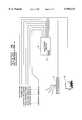
- FIG. 1illustrates a high level diagrammatic illustration of a machine prognostic system
- FIG. 2illustrates a plurality of machine parameter connections to an electronic module of the machine prognostic system
- FIG. 3illustrates a method performed by the electronic module to trend machine parameters
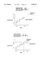
- FIG. 4illustrates an example of a trend of a machine parameter
- FIG. 5illustrates an example group of data points used to fit a line segment of a trend
- FIG. 6illustrates a method for projecting the line segment
- FIG. 7illustrates a look-up table including a plurality of trend slope values that correspond to a plurality of slope confidence factors
- FIG. 8illustrates a look-up table including a plurality of trend duration values that correspond to a plurality of duration confidence factors
- FIG. 9illustrates a look-up table including a plurality of trend distance values that correspond to a plurality of distance confidence factors
- FIG. 10illustrates a look-up table including a plurality of significance factors that correspond to a plurality of severity indices.
- FIG. 11illustrates an example projection of a line segment.
- a machine prognostic systemis shown generally by the number 10 and is a data acquisition, analysis, storage, and display system for a work machine 12.
- the machine prognostic system 10monitors and derives machine component information and analyzes the resulting data to indicate and/or predict impending component or system failures.
- FIG. 1illustrates a variety of potential communication systems 14 that may be used to transfer data from the work machine 12 to a central computer system 16 for analysis.
- the datamay be transferred by a satellite system back to the central computer system 16.
- the datamay be transferred by a cellular telephone system or by storing data on a computer disk which is then mailed to the central computer site for analysis.
- Subsets of the dataare also transmitted to a display module (not shown) in the operator compartment of the work machine 12 for presentation to the operator in the form of gauges and warning messages.
- gauge valuesare displayed in the operator compartment.
- alarms and warning/instructional messagesare also displayed.
- sensed datais directly sampled by sensors 18 of a type well-known in the art for producing electrical signals in response to the level of operational parameters and includes pulse-width modulated sensor data, frequency-based data, five volt analog sensor data, and switch data that has been effectively debounced.
- the sensorsare connected to an electronic module 20 for delivery of the sensor signals.
- the sensor signalsare delivered to the electronic module 20 by either direct connection of analog sensors, connection by way of an RS485 link, or over a datalink governed by SAE specifications J1587 and J1708.
- a push-buttonis also included to trigger the acquisition of a snapshot of data. Connection is also provided from the machine battery and key switch to the electronic module 20.
- the electronic module 20includes a microprocessor, a lower level communications board (not shown) of a type well-known in the art, and a memory section 24 including high level flash memory and battery backed RAM.
- the electronic modulealso includes a pair of RS232 connections, one being available for connection to the satellite communications system 21 and the other being available for connection to an off-board computer 22 used in download of data and initialization of the system.
- the off-board computer 22is a laptop personal computer.
- performance baselinesare stored in an array within the memory device located in the electronic module 20. These baselines are used during key, repeatable performance checks of the machine to help verify machine/component health and, as discussed below, are used as reference points to determine whether the machine is in an operating condition in which machine parameters are to be processed and stored.
- a subset of parameters for which trend data is to be producedis either predefined or defined via the off-board computer 22 or the central computer 16.
- Each parameterincludes a dependency definition that identifies the conditions under which data will be stored for trending purposes.
- the dependency definitionis selected to indicate the normal operating conditions of the machine; for example, when engine RPM or boost pressure are above a predetermined levels.
- the trending definition for each parametermay vary and may be a function of several other machine parameters that shall be referred to as dependencies.
- Trend datais gathered and stored in memory as the specified dependency definition is met over a specified trend period, which is measured either in time, such as over a period of ten hours, or in counts, such as over a period of ten transmission shifts. Trend data is only obtained while the engine is running.
- the maximum, minimum, or cumulative value of data gathered during this periodis then stored as a single trend point with counts to determine the average value and/or the points available.
- the determination of whether to use the average, maximum, or minimum value to obtain the trend pointis based on the system designer's decision regarding which type of calculation would provide the best indication of changes in engine performance or impending failures. It should also be understood that multiple values could be calculated for the same sensed parameter, i.e., trend points could be calculated to indicate both an average value and a minimum value for a designated machine parameter.
- the electronic module 20first determines whether the engine is running.
- the engineis determined to be running if engine speed exceeds cranking engine speed. If the engine is not running, then the method will not proceed. If the engine is running, the electronic module 20 reads the sensed machine parameters from the datalink or other inputs.
- the electronic module 20determines whether that parameter is to be processed to provide trend data. If trend data is to be provided, the trending definition is retrieved and the dependency parameters are checked to determine whether the dependency definition is satisfied.
- the dependency definition for each operating parameter of interestis defined in terms of other sensed machine parameters. For example, the dependency definition for boost pressure may be satisfied only when engine RPM is greater than a low operating speed and less than a high operating speed, when the engine rack setting is greater than a predetermined level, and when the jacket water temperature is greater than a predefined operating temperature. That is, values for boost pressure are only saved and processed for producing trend information when the above conditions are satisfied. In this way, all boost pressure values used to produce the trend data will have been acquired when the engine is in the same general operating condition. It should be understood that the actual ranges, minimums, and maximums used in the dependency definitions are determined empirically to define the operating conditions of interest and will vary from machine to machine and application to application.
- the value of the sensed parameteris stored. This process is continued until either the time period over which each trend point is to be determined or the number of events for which each trend point is to be determined is reached at which point the electronic module 20 calculates and stores the trend point.
- the time period or number of eventsis selected in response to the designer's desire for precision, the availability of memory space in the memory device, and the length of time or number of counts required to obtain meaningful trend points.
- the calculation of the trend pointmay include accumulating the stored values, selecting the maximum stored value, or selecting the minimum stored value.
- the calculated trend pointis saved and the data array for that parameter is then cleared to allow for the storage of data for calculation of the next trend point for that parameter.
- Trend data obtained by way of the method of FIG. 3is illustrated in FIG. 4. While the illustrated data has a substantial variance, straight lines can be fit to the data to illustrate the general trend of the data by known curve fitting techniques, such as the least-squares method.
- the overall trendis formed by storing a specified number of points in the memory device depending on the size of the available memory area and the length of the desired historical data base.
- calculated valuessuch as net horsepower or driveline torque, may also be trended in a similar manner.
- these calculated valuesare determined by the electronic module 20 according to predetermined definitions in response to a plurality of sensed parameter signals.
- Trend datamay be reset and the definitions may be redefined by the off-board system 22 via one of the communication ports. For example, if a particular application of the machine requires a different dependency definition for one or more of the sensed parameters, the off-board system 22 is used to modify the dependency definition by providing commands to erase a given array including a given dependency definition and replace that definition with a new dependency definition. Similarly, this function may be performed by the central computer system 16 via the communication system 14.
- trending functionsare defined in terms of slope and duration of particular trends.
- the sloperefers to the actual slope of the line segment and is indicative of how fast the trend is approaching a predetermined warning level.
- the durationindicates the duration in time that data has been collected, e.g., the duration indicates the history of the trend.
- Another trending functionis referred to as the distance function.
- the distance functionis related to the position of the last data point of the trend, and indicates the relative distance of the last data point to the predetermined warning level.
- FIG. 5represents a collection of data points that are stored in a two-dimensional map representing a Cartesian coordinate system. Using the figure shown on FIG. 5, the trending functions may be determined as follows:
- the present inventionis directed towards determining when the line segment should be projected in order to determine prognostic information. This determination is based on the trending functions.
- the present inventionis described by a method 600 that determines the point in time in which the trend should be projected and the duration of the projection.
- the methodnormalizes the slope, duration and distance functions.
- FIG. 7illustrates a slope function that has been normalized.
- the slope functionrepresents the slope of the trend or line segment between 0° and 90°. However, when the slope is normalized, the value of the slope function falls between 0 and 1.
- a confidence factor for the normalized slopeis determined in accordance with block 610 of FIG. 6.
- a confidence factoris defined as the probability that the particular function, e.g., slope function, that is generated is a good approximation of the particular function of the actual trend.
- the confidence factormay be determined in response to a linear, sigmoid or gaussian function.
- FIG. 7represents a look-up table that stores a plurality of normalized slope values that correspond to a plurality of slope confidence factors.
- the x-axisrefers to the normalized slope and the y-axis refers to the confidence factor which is represented by symbol z 1 .
- the confidence factor for the slope functionranges in magnitude from 0 to 1.0.
- a two-dimensional look-up table of a type well known in the artis used to store the desired characteristics. The number of characteristics stored in memory is dependent upon the desired precision of the system.
- the method of the present inventionselects the corresponding slope confidence factor. Interpolation may be used to determine the slope confidence factor in the event that the stored values fall between the discrete values stored in memory.
- the table valuesare based from simulation and analysis of empirical data. Continuing this example, assuming a normalized slope of 0.5 has been calculated, then the method would select a confidence factor of 0.5.
- the slope confidence factormay be determined according to the following equation: ##EQU2## where k represents a predetermined gain value and the negative exponent represents the normalized slope.
- the confidence factor for the duration functionis computed.
- FIG. 8represents a look-up table that stores a plurality of normalized duration values that correspond to a plurality of duration confidence factors.
- the confidence factor for the duration functionis represented by symbol Z 2 and ranges in magnitude from 0 to 1.0. As an example, assuming that a normalized duration of 0.6 has been calculated, then the method selects a confidence factor of 0.8.
- the confidence factor for the duration functionmay be determined in accordance with the following equation: ##EQU3## where the negative exponent represents the normalized duration.
- the confidence factor for the distance functionis computed.
- FIG. 9represents a look-up table that stores a plurality of normalized distance values that correspond to a plurality of distance confidence factors.
- the confidence factor for the distance functionis represented by symbol Z 3 and ranges in magnitude from 0 to 1.0. As an example, assuming a normalized distance of 0.6 has been calculated, then the method selects a confidence factor of 0.4.
- the confidence factor for the distance functionmay be determined in accordance with the following equation: ##EQU4## where the exponent represents the normalized distance.
- a significance factoris defined as the probability that a significant trend of a parameter or a variable exists.
- the significance factormay be computed by the following equation: ##EQU5## where w 1 , w 2 , w 3 are predetermined values that represent preferred weighting factors.
- the significance factorsare shown to be a combination of the individual confidence factors, the significance factor may be determined in other ways, including determining a significance factor for each function individually and then combining the significance factors for each function to obtain an overall significance factor.
- a severity indexis defined as the probability that the machine or component on the machine will experience a fault.
- the severity indexindicates how severe the machine is being used. For example, if the severity index is high, it may be desirable to use the machine for less severe applications to avoid an unanticipated failure. Consequently, the machine can be used until the next programmed maintenance is scheduled.
- the data trend or line segmentshould be projected. Assuming that the line segment should be projected, then method step 625 determines the projected duration of the last data point to the warning level.
- the data trend or line segmentis projected by simply extending the line segment to the warning level based on the slope, as shown in FIG. 11.
- the time duration of the projectionindicates how long the machine can be used in the current environment before a failure will likely occur.
- the time period to the warning leveli.e., the time period in which the component may fail, may be determined according to: ##EQU6##
- the time duration of the projectioni.e., the time that a fault condition may occur, may be indicated to the operator via a display panel.
- the time duration of the projectionmay also be stored for use by diagnostic personnel at both of the work machine 12 and central computer system 16.
- Work machinessuch as over-the-highway trucks and large mining and construction machines represent large capital investments and significantly reduce overall productivity for the owner when they are being repaired.
- the present inventionprovide service and supervisory personnel with historical data relating to sensed machine parameters. This historical data is then used to diagnose failures, predict future failures, and evaluate machine and/or operator performance.
Landscapes
- Physics & Mathematics (AREA)
- General Physics & Mathematics (AREA)
- Engineering & Computer Science (AREA)
- Automation & Control Theory (AREA)
- Testing And Monitoring For Control Systems (AREA)
- Control Of Electric Motors In General (AREA)
Abstract
Description
The invention relates generally to a device for predicting a fault condition, and more particularly, to a method and apparatus for predicting a fault condition in response to the trend of a machine parameter.
For service and diagnostic purposes, machines are sometimes equipped with sensors for measuring operating conditions such as engine RPM, oil pressure, water temperature, boost pressure, oil contamination, electric motor current, hydraulic pressure, system voltage, and the like. In some cases, storage devices are provided to compile a data base for later evaluation of machine performance and to aid in diagnosis. Service personnel examine the accrued data to get a better picture of the causes of any machine performance degradation, wear, or failure. Similarly, service personnel evaluate the stored data to predict future failures and associated collateral damages, and to correct any problems before total component failure.
In addition, these stored parameters may be examined by service or supervisory personnel to evaluate machine and/or operator performance to ensure maximum productivity of the machine. These issues are particularly pertinent to over-the-highway trucks and large work machines such as off-highway mining trucks, hydraulic excavators, track-type tractors, wheel loaders, and the like. These machines represent large capital investments and are capable of substantial productivity when operating. It is therefore important to predict significant performance loss, wear and catastrophic failures so servicing can be scheduled during periods in which productivity will be less affected and so minor problems can be repaired before they lead to catastrophic failures.
Similarly, it is sometimes advantageous to accumulate parameters only when the machine is in a particular operating condition. This type of information is predominantly used during performance evaluation but may also be used in failure diagnosis and prognosis. For example, the length of time spent in a particular gear while the machine is loaded may be needed to evaluate machine performance.
The present invention is directed to overcoming one or more of the problems set forth above.
An apparatus for predicting a fault condition for a machine is disclosed. The machine has a plurality of parameters being dependent upon machine performance. A sensor connected to the machine produces an electrical signal in response to one of the plurality of machine parameters. A computer produces a data trend of the parameter in response to the electrical signal, calculates the duration and slope of the trend, and predicts the time period in which the trend will exceed the warning level.
For a better understanding of the present invention, reference may be made to the accompanying drawings, in which:
FIG. 1 illustrates a high level diagrammatic illustration of a machine prognostic system;
FIG. 2 illustrates a plurality of machine parameter connections to an electronic module of the machine prognostic system;
FIG. 3 illustrates a method performed by the electronic module to trend machine parameters;
FIG. 4 illustrates an example of a trend of a machine parameter;
FIG. 5 illustrates an example group of data points used to fit a line segment of a trend;
FIG. 6 illustrates a method for projecting the line segment;
FIG. 7 illustrates a look-up table including a plurality of trend slope values that correspond to a plurality of slope confidence factors;
FIG. 8 illustrates a look-up table including a plurality of trend duration values that correspond to a plurality of duration confidence factors;
FIG. 9 illustrates a look-up table including a plurality of trend distance values that correspond to a plurality of distance confidence factors;
FIG. 10 illustrates a look-up table including a plurality of significance factors that correspond to a plurality of severity indices; and
FIG. 11 illustrates an example projection of a line segment.
Referring to FIG. 1, a machine prognostic system is shown generally by thenumber 10 and is a data acquisition, analysis, storage, and display system for awork machine 12. Employing a complement of on-board and off-board hardware and software, the machineprognostic system 10 monitors and derives machine component information and analyzes the resulting data to indicate and/or predict impending component or system failures.
FIG. 1 illustrates a variety ofpotential communication systems 14 that may be used to transfer data from thework machine 12 to acentral computer system 16 for analysis. For example, the data may be transferred by a satellite system back to thecentral computer system 16. Alternatively, the data may be transferred by a cellular telephone system or by storing data on a computer disk which is then mailed to the central computer site for analysis.
It should be understood that all aspects of the present invention could be located on-board thework machine 12 thereby eliminating the need for acommunication system 14; however, thecentral computer system 16 allows an entire fleet to be monitored at a central location.
Subsets of the data are also transmitted to a display module (not shown) in the operator compartment of thework machine 12 for presentation to the operator in the form of gauges and warning messages. During normal operation, gauge values are displayed in the operator compartment. During out-of-spec conditions, alarms and warning/instructional messages are also displayed.
In the preferred embodiment, sensed data is directly sampled bysensors 18 of a type well-known in the art for producing electrical signals in response to the level of operational parameters and includes pulse-width modulated sensor data, frequency-based data, five volt analog sensor data, and switch data that has been effectively debounced. The sensors are connected to anelectronic module 20 for delivery of the sensor signals.
In the embodiment of FIGS. 1 and 2, the sensor signals are delivered to theelectronic module 20 by either direct connection of analog sensors, connection by way of an RS485 link, or over a datalink governed by SAE specifications J1587 and J1708. A push-button is also included to trigger the acquisition of a snapshot of data. Connection is also provided from the machine battery and key switch to theelectronic module 20.
In the preferred embodiment, theelectronic module 20 includes a microprocessor, a lower level communications board (not shown) of a type well-known in the art, and amemory section 24 including high level flash memory and battery backed RAM. The electronic module also includes a pair of RS232 connections, one being available for connection to thesatellite communications system 21 and the other being available for connection to an off-board computer 22 used in download of data and initialization of the system. In the preferred embodiment, the off-board computer 22 is a laptop personal computer.
To document the performance of the machine and/or its major components, performance baselines are stored in an array within the memory device located in theelectronic module 20. These baselines are used during key, repeatable performance checks of the machine to help verify machine/component health and, as discussed below, are used as reference points to determine whether the machine is in an operating condition in which machine parameters are to be processed and stored.
A subset of parameters for which trend data is to be produced is either predefined or defined via the off-board computer 22 or thecentral computer 16. Each parameter includes a dependency definition that identifies the conditions under which data will be stored for trending purposes. Typically, the dependency definition is selected to indicate the normal operating conditions of the machine; for example, when engine RPM or boost pressure are above a predetermined levels. The trending definition for each parameter may vary and may be a function of several other machine parameters that shall be referred to as dependencies. Trend data is gathered and stored in memory as the specified dependency definition is met over a specified trend period, which is measured either in time, such as over a period of ten hours, or in counts, such as over a period of ten transmission shifts. Trend data is only obtained while the engine is running. Based on the specified trend type, the maximum, minimum, or cumulative value of data gathered during this period is then stored as a single trend point with counts to determine the average value and/or the points available. The determination of whether to use the average, maximum, or minimum value to obtain the trend point is based on the system designer's decision regarding which type of calculation would provide the best indication of changes in engine performance or impending failures. It should also be understood that multiple values could be calculated for the same sensed parameter, i.e., trend points could be calculated to indicate both an average value and a minimum value for a designated machine parameter.
Referring now to FIG. 3, one method executed by the processor within theelectronic module 20 to perform the above functions is now described. Theelectronic module 20 first determines whether the engine is running. Advantageously, the engine is determined to be running if engine speed exceeds cranking engine speed. If the engine is not running, then the method will not proceed. If the engine is running, theelectronic module 20 reads the sensed machine parameters from the datalink or other inputs.
For each of the sensed parameters, theelectronic module 20 determines whether that parameter is to be processed to provide trend data. If trend data is to be provided, the trending definition is retrieved and the dependency parameters are checked to determine whether the dependency definition is satisfied. The dependency definition for each operating parameter of interest is defined in terms of other sensed machine parameters. For example, the dependency definition for boost pressure may be satisfied only when engine RPM is greater than a low operating speed and less than a high operating speed, when the engine rack setting is greater than a predetermined level, and when the jacket water temperature is greater than a predefined operating temperature. That is, values for boost pressure are only saved and processed for producing trend information when the above conditions are satisfied. In this way, all boost pressure values used to produce the trend data will have been acquired when the engine is in the same general operating condition. It should be understood that the actual ranges, minimums, and maximums used in the dependency definitions are determined empirically to define the operating conditions of interest and will vary from machine to machine and application to application.
If the dependency definition is satisfied, the value of the sensed parameter is stored. This process is continued until either the time period over which each trend point is to be determined or the number of events for which each trend point is to be determined is reached at which point theelectronic module 20 calculates and stores the trend point. The time period or number of events is selected in response to the designer's desire for precision, the availability of memory space in the memory device, and the length of time or number of counts required to obtain meaningful trend points. The calculation of the trend point may include accumulating the stored values, selecting the maximum stored value, or selecting the minimum stored value. The calculated trend point is saved and the data array for that parameter is then cleared to allow for the storage of data for calculation of the next trend point for that parameter.
Trend data obtained by way of the method of FIG. 3 is illustrated in FIG. 4. While the illustrated data has a substantial variance, straight lines can be fit to the data to illustrate the general trend of the data by known curve fitting techniques, such as the least-squares method. The overall trend is formed by storing a specified number of points in the memory device depending on the size of the available memory area and the length of the desired historical data base.
In addition to the trend data produced for sensed parameters, it should be understood that calculated values, such as net horsepower or driveline torque, may also be trended in a similar manner. Typically, these calculated values are determined by theelectronic module 20 according to predetermined definitions in response to a plurality of sensed parameter signals.
Trend data may be reset and the definitions may be redefined by the off-board system 22 via one of the communication ports. For example, if a particular application of the machine requires a different dependency definition for one or more of the sensed parameters, the off-board system 22 is used to modify the dependency definition by providing commands to erase a given array including a given dependency definition and replace that definition with a new dependency definition. Similarly, this function may be performed by thecentral computer system 16 via thecommunication system 14.
Based on the slope and duration of the trends illustrated in FIG. 4, certain judgments can be made regarding the likelihood of impending component or system failure based on machine performance loss, degradation or wear. To help make these judgments, trending functions are defined in terms of slope and duration of particular trends. The slope refers to the actual slope of the line segment and is indicative of how fast the trend is approaching a predetermined warning level. The duration indicates the duration in time that data has been collected, e.g., the duration indicates the history of the trend. Another trending function is referred to as the distance function. The distance function is related to the position of the last data point of the trend, and indicates the relative distance of the last data point to the predetermined warning level. Reference is now made to FIG. 5, which represents a collection of data points that are stored in a two-dimensional map representing a Cartesian coordinate system. Using the figure shown on FIG. 5, the trending functions may be determined as follows:
distance=y.sub.3 -y.sub.2
duration=x.sub.2 -x.sub.1
Finally, the slope is determined by: ##EQU1##
Once a trend has been produced, i.e., a line segment has been constructed, the present invention is directed towards determining when the line segment should be projected in order to determine prognostic information. This determination is based on the trending functions.
Referring now to FIG. 6, the present invention is described by a method 600 that determines the point in time in which the trend should be projected and the duration of the projection. Atblock 605 the method normalizes the slope, duration and distance functions.
For example, reference is made to FIG. 7, which illustrates a slope function that has been normalized. For example, the slope function represents the slope of the trend or line segment between 0° and 90°. However, when the slope is normalized, the value of the slope function falls between 0 and 1.
Once the slope has been normalized, then a confidence factor for the normalized slope is determined in accordance withblock 610 of FIG. 6. A confidence factor is defined as the probability that the particular function, e.g., slope function, that is generated is a good approximation of the particular function of the actual trend. The confidence factor may be determined in response to a linear, sigmoid or gaussian function.
For example, FIG. 7 represents a look-up table that stores a plurality of normalized slope values that correspond to a plurality of slope confidence factors. As shown, the x-axis refers to the normalized slope and the y-axis refers to the confidence factor which is represented by symbol z1. The confidence factor for the slope function ranges in magnitude from 0 to 1.0. In one embodiment, a two-dimensional look-up table of a type well known in the art is used to store the desired characteristics. The number of characteristics stored in memory is dependent upon the desired precision of the system. Based on the actual slope value, the method of the present invention selects the corresponding slope confidence factor. Interpolation may be used to determine the slope confidence factor in the event that the stored values fall between the discrete values stored in memory. The table values are based from simulation and analysis of empirical data. Continuing this example, assuming a normalized slope of 0.5 has been calculated, then the method would select a confidence factor of 0.5.
Alternatively, the slope confidence factor may be determined according to the following equation: ##EQU2## where k represents a predetermined gain value and the negative exponent represents the normalized slope.
Once the duration function is normalized, then the confidence factor for the duration function is computed. Reference is now made to FIG. 8, which represents a look-up table that stores a plurality of normalized duration values that correspond to a plurality of duration confidence factors. The confidence factor for the duration function is represented by symbol Z2 and ranges in magnitude from 0 to 1.0. As an example, assuming that a normalized duration of 0.6 has been calculated, then the method selects a confidence factor of 0.8.
Alternatively, the confidence factor for the duration function may be determined in accordance with the following equation: ##EQU3## where the negative exponent represents the normalized duration.
Once the distance function is normalized, then the confidence factor for the distance function is computed. Referring now to FIG. 9, which represents a look-up table that stores a plurality of normalized distance values that correspond to a plurality of distance confidence factors, the confidence factor for the distance function is determined. The confidence factor for the distance function is represented by symbol Z3 and ranges in magnitude from 0 to 1.0. As an example, assuming a normalized distance of 0.6 has been calculated, then the method selects a confidence factor of 0.4.
Alternatively, the confidence factor for the distance function may be determined in accordance with the following equation: ##EQU4## where the exponent represents the normalized distance.
In accordance withblock 615 of FIG. 6, the confidence factors are combined to determine a significance factor. A significance factor is defined as the probability that a significant trend of a parameter or a variable exists. The significance factor may be computed by the following equation: ##EQU5## where w1, w2, w3 are predetermined values that represent preferred weighting factors.
Although the significance factors are shown to be a combination of the individual confidence factors, the significance factor may be determined in other ways, including determining a significance factor for each function individually and then combining the significance factors for each function to obtain an overall significance factor.
Referring now to FIG. 10, the significance factor is trended and stored in a two-dimensional look-up table against a severity index. A severity index is defined as the probability that the machine or component on the machine will experience a fault. In other words, the severity index indicates how severe the machine is being used. For example, if the severity index is high, it may be desirable to use the machine for less severe applications to avoid an unanticipated failure. Consequently, the machine can be used until the next programmed maintenance is scheduled.
Referring back tomethod step 620 of FIG. 6, if the severity index reaches a caution threshold, then the data trend or line segment should be projected. Assuming that the line segment should be projected, thenmethod step 625 determines the projected duration of the last data point to the warning level. The data trend or line segment is projected by simply extending the line segment to the warning level based on the slope, as shown in FIG. 11. Thus, the time duration of the projection indicates how long the machine can be used in the current environment before a failure will likely occur. For example, the time period to the warning level, i.e., the time period in which the component may fail, may be determined according to: ##EQU6##
The time duration of the projection, i.e., the time that a fault condition may occur, may be indicated to the operator via a display panel. The time duration of the projection may also be stored for use by diagnostic personnel at both of thework machine 12 andcentral computer system 16.
Work machines such as over-the-highway trucks and large mining and construction machines represent large capital investments and significantly reduce overall productivity for the owner when they are being repaired. To reduce the loss of productivity, the present invention provide service and supervisory personnel with historical data relating to sensed machine parameters. This historical data is then used to diagnose failures, predict future failures, and evaluate machine and/or operator performance.
Other aspects, objects, and advantages of this invention can be obtained from a study of the drawings, the disclosure, and the appended claims.
Claims (16)
1. An apparatus for predicting a fault condition, comprising:
a machine having a plurality of parameters being dependent upon machine performance;
a sensor connected to the machine and adapted to produce an electrical signal in response to one of the plurality of machine parameters;
means for producing a data trend of the parameter in response to the electrical signal;
means for calculating the duration and slope of the trend;
means for calculating the distance from the last data point of the trend to a warning level;
means for determining a severity index; and
means for predicting the time period in which the trend will exceed the warning level in response to the duration, slope, and distance, and modifying the use of the machine as a function of the severity index and the predicted time period.
2. An apparatus, as set forth in claim 1, including means for normalizing the trend, duration and distance magnitudes.
3. An apparatus, as set forth in claim 2, including means for selecting a confidence factor for each of the normalized slope, duration and distance magnitudes.
4. An apparatus, as set forth in claim 3, including means for storing a plurality of normalized trend, duration and distance magnitudes that correspond to a plurality of associated confidence factors, comparing the actual normalized magnitude to the stored normalized magnitudes, and selecting a corresponding confidence factor for each of the normalized slope, duration and distance magnitudes.
5. An apparatus, as set forth in claim 4, including means for combining the slope, duration, and distance confidence factors to obtain a significance factor.
6. An apparatus, as set forth in claim 5, including means for trending the significance factor against the severity index.
7. An apparatus, as set forth in claim 6, including means for comparing the severity index with a caution threshold and projecting the data trend in response to the severity index exceeding the caution threshold.
8. An apparatus, as set forth in claim 7, including means for projecting the data trend by extending the data trend to the warning level based on the slope of the data trend.
9. A method for predicting a fault condition for a machine having a plurality of parameters being dependent upon machine performance, the method including the following steps:
producing an electrical signal in response to one of the plurality of machine parameters;
producing a data trend of the parameter in response to the electrical signal;
calculating the duration and slope of the trend;
calculating the distance from the last data point of the trend to a warning level;
determining a severity index;
predicting the time period in which the trend will exceed the warning level in response to the duration, slope, and distance; and
modifying the use of the machine as a function of the severity index and the predicted time period.
10. A method, as set forth in claim 9, including the steps of normalizing the trend, duration and distance magnitudes.
11. A method, as set forth in claim 10, including the steps of selecting a confidence factor for each of the normalized slope, duration and distance magnitudes.
12. A method, as set forth in claim 11, including the steps of storing a plurality of normalized trend, duration and distance magnitudes that correspond to a plurality of associated confidence factors, comparing the actual normalized magnitude to the stored normalized magnitudes, and selecting a corresponding confidence factor for each of the normalized slope, duration and distance magnitudes.
13. A method, as set forth in claim 12, including the step of combining the slope, duration, and distance confidence factors to obtain a significance factor.
14. A method, as set forth in claim 13, including the step of trending the significance factor against the severity index.
15. A method, as set forth in claim 14, the steps of comparing the severity index with a caution threshold and projecting the data trend in response to the severity index exceeding the caution threshold.
16. A method, as set forth in claim 15, including the step of projecting the data trend by extending the data trend to the warning level based on the slope of the data trend.
Priority Applications (6)
| Application Number | Priority Date | Filing Date | Title |
|---|---|---|---|
| US08/870,113US5950147A (en) | 1997-06-05 | 1997-06-05 | Method and apparatus for predicting a fault condition |
| DE19880924TDE19880924T1 (en) | 1997-06-05 | 1998-05-11 | Method and device for predicting a fault condition |
| AU73821/98AAU736788B2 (en) | 1997-06-05 | 1998-05-11 | Method and apparatus for predicting a fault condition |
| GB9900523AGB2330231B (en) | 1997-06-05 | 1998-05-11 | Method and apparatus for predicting a fault condition |
| JP11502441AJP2000516374A (en) | 1997-06-05 | 1998-05-11 | Failure state prediction method and device |
| PCT/US1998/009658WO1998055904A1 (en) | 1997-06-05 | 1998-05-11 | Method and apparatus for predicting a fault condition |
Applications Claiming Priority (1)
| Application Number | Priority Date | Filing Date | Title |
|---|---|---|---|
| US08/870,113US5950147A (en) | 1997-06-05 | 1997-06-05 | Method and apparatus for predicting a fault condition |
Publications (1)
| Publication Number | Publication Date |
|---|---|
| US5950147Atrue US5950147A (en) | 1999-09-07 |
Family
ID=25354812
Family Applications (1)
| Application Number | Title | Priority Date | Filing Date |
|---|---|---|---|
| US08/870,113Expired - LifetimeUS5950147A (en) | 1997-06-05 | 1997-06-05 | Method and apparatus for predicting a fault condition |
Country Status (6)
| Country | Link |
|---|---|
| US (1) | US5950147A (en) |
| JP (1) | JP2000516374A (en) |
| AU (1) | AU736788B2 (en) |
| DE (1) | DE19880924T1 (en) |
| GB (1) | GB2330231B (en) |
| WO (1) | WO1998055904A1 (en) |
Cited By (112)
| Publication number | Priority date | Publication date | Assignee | Title |
|---|---|---|---|---|
| US6119074A (en)* | 1998-05-20 | 2000-09-12 | Caterpillar Inc. | Method and apparatus of predicting a fault condition |
| US6243628B1 (en)* | 1999-09-07 | 2001-06-05 | General Electric Company | System and method for predicting impending failures in a locomotive |
| US6263265B1 (en) | 1999-10-01 | 2001-07-17 | General Electric Company | Web information vault |
| US6301531B1 (en)* | 1999-08-23 | 2001-10-09 | General Electric Company | Vehicle maintenance management system and method |
| US6324659B1 (en) | 1999-10-28 | 2001-11-27 | General Electric Company | Method and system for identifying critical faults in machines |
| US6336065B1 (en) | 1999-10-28 | 2002-01-01 | General Electric Company | Method and system for analyzing fault and snapshot operational parameter data for diagnostics of machine malfunctions |
| US6338152B1 (en) | 1999-10-28 | 2002-01-08 | General Electric Company | Method and system for remotely managing communication of data used for predicting malfunctions in a plurality of machines |
| US6349248B1 (en) | 1999-10-28 | 2002-02-19 | General Electric Company | Method and system for predicting failures in a power resistive grid of a vehicle |
| US20020065698A1 (en)* | 1999-08-23 | 2002-05-30 | Schick Louis A. | System and method for managing a fleet of remote assets |
| US6401056B1 (en)* | 1999-12-27 | 2002-06-04 | General Electric Company | Methods and apparatus for evaluating tool performance |
| US6405108B1 (en) | 1999-10-28 | 2002-06-11 | General Electric Company | Process and system for developing predictive diagnostics algorithms in a machine |
| US6415209B1 (en)* | 2000-05-02 | 2002-07-02 | Ssi Technologies, Inc. | Marine accessory systems |
| US20020116148A1 (en)* | 2000-12-21 | 2002-08-22 | Joachim Bertsch | Method for maintenance planning for technical devices |
| US6442511B1 (en)* | 1999-09-03 | 2002-08-27 | Caterpillar Inc. | Method and apparatus for determining the severity of a trend toward an impending machine failure and responding to the same |
| US6446026B1 (en) | 1999-10-28 | 2002-09-03 | General Electric Company | Method and system for identifying performance degradation of a cooling subsystem in a locomotive |
| US20020133320A1 (en)* | 2001-01-19 | 2002-09-19 | Wegerich Stephan W. | Adaptive modeling of changed states in predictive condition monitoring |
| US20020183866A1 (en)* | 1999-04-02 | 2002-12-05 | Dean Jason Arthur | Method and system for diagnosing machine malfunctions |
| US20030005364A1 (en)* | 2001-06-14 | 2003-01-02 | International Business Machines Corporation | Method for estimating number of internationalization faults in software code |
| US20030014692A1 (en)* | 2001-03-08 | 2003-01-16 | California Institute Of Technology | Exception analysis for multimissions |
| US20030055666A1 (en)* | 1999-08-23 | 2003-03-20 | Roddy Nicholas E. | System and method for managing a fleet of remote assets |
| US20030055607A1 (en)* | 2001-06-11 | 2003-03-20 | Wegerich Stephan W. | Residual signal alert generation for condition monitoring using approximated SPRT distribution |
| US6543007B1 (en) | 1999-10-28 | 2003-04-01 | General Electric Company | Process and system for configuring repair codes for diagnostics of machine malfunctions |
| US20030137194A1 (en)* | 2001-11-27 | 2003-07-24 | White Tommy E. | Data collection and manipulation apparatus and method |
| US6609036B1 (en) | 2000-06-09 | 2003-08-19 | Randall L. Bickford | Surveillance system and method having parameter estimation and operating mode partitioning |
| US6615367B1 (en) | 1999-10-28 | 2003-09-02 | General Electric Company | Method and apparatus for diagnosing difficult to diagnose faults in a complex system |
| US6622264B1 (en) | 1999-10-28 | 2003-09-16 | General Electric Company | Process and system for analyzing fault log data from a machine so as to identify faults predictive of machine failures |
| US6625589B1 (en) | 1999-10-28 | 2003-09-23 | General Electric Company | Method for adaptive threshold computation for time and frequency based anomalous feature identification in fault log data |
| US20030191581A1 (en)* | 1999-08-31 | 2003-10-09 | Hitachi, Ltd. | Method and apparatus for gathering vehicle information |
| US6636771B1 (en) | 1999-04-02 | 2003-10-21 | General Electric Company | Method and system for analyzing continuous parameter data for diagnostics and repairs |
| US6643801B1 (en)* | 1999-10-28 | 2003-11-04 | General Electric Company | Method and system for estimating time of occurrence of machine-disabling failures |
| US20040002776A1 (en)* | 2000-06-09 | 2004-01-01 | Bickford Randall L. | Surveillance system and method having an operating mode partitioned fault classification model |
| US20040025082A1 (en)* | 2002-07-31 | 2004-02-05 | Roddy Nicholas Edward | Method and system for monitoring problem resolution of a machine |
| US20040064225A1 (en)* | 2002-09-30 | 2004-04-01 | Jammu Vinay Bhaskar | Method for identifying a loss of utilization of mobile assets |
| US20040122618A1 (en)* | 2002-12-23 | 2004-06-24 | Jin Suzuki | Component life indicator |
| US20040143417A1 (en)* | 1999-10-28 | 2004-07-22 | Hedlund Eric H. | Apparatus and method for performance and fault data analysis |
| US6795935B1 (en) | 1999-10-28 | 2004-09-21 | General Electric Company | Diagnosis of faults in a complex system |
| US20040186687A1 (en)* | 2001-05-08 | 2004-09-23 | Hiroshi Ogura | Working machine, trouble diagnosis system of working machine, and maintenance system of working machine |
| US6877360B1 (en)* | 1998-04-02 | 2005-04-12 | Rockwell Automation Technologies, Inc. | System and method for dynamic lubrication adjustment for a lubrication analysis system |
| US20050165519A1 (en)* | 2004-01-28 | 2005-07-28 | Ariyur Kartik B. | Trending system and method using window filtering |
| US20050171661A1 (en)* | 1999-10-28 | 2005-08-04 | Aiman Abdel-Malek | Diagnosis and repair system and method |
| US20050204803A1 (en)* | 2004-02-23 | 2005-09-22 | Fmc Kongsberg Subsea As | Method for testing an electric motor |
| US20050251370A1 (en)* | 2004-05-10 | 2005-11-10 | Li Jonathan Q | Combining multiple independent sources of information for classification of devices under test |
| US20060058898A1 (en)* | 2004-09-10 | 2006-03-16 | Emigholz Kenneth F | System and method for abnormal event detection in the operation of continuous industrial processes |
| US20060074599A1 (en)* | 2004-09-10 | 2006-04-06 | Emigholz Kenneth F | Application of abnormal event detection technology to olefins recovery trains |
| US7047164B1 (en)* | 2000-05-30 | 2006-05-16 | Paradyne Corporation | Port trend analysis system and method for trending port burst information associated with a communications device |
| US7051044B1 (en) | 1999-10-28 | 2006-05-23 | General Electric Company | Method and system for remotely managing communication of data used for predicting malfunctions in a plurality of machines |
| US7072797B2 (en) | 2003-08-29 | 2006-07-04 | Honeywell International, Inc. | Trending system and method using monotonic regression |
| US20060229854A1 (en)* | 2005-04-08 | 2006-10-12 | Caterpillar Inc. | Computer system architecture for probabilistic modeling |
| US20060230018A1 (en)* | 2005-04-08 | 2006-10-12 | Caterpillar Inc. | Mahalanobis distance genetic algorithm (MDGA) method and system |
| US20060230313A1 (en)* | 2005-04-08 | 2006-10-12 | Caterpillar Inc. | Diagnostic and prognostic method and system |
| US7134323B1 (en) | 1998-04-02 | 2006-11-14 | Rockwell Automation Technologies, Inc. | System and method for dynamic lubrication adjustment for a lubrication analysis system |
| US20070118338A1 (en)* | 2005-11-18 | 2007-05-24 | Caterpillar Inc. | Process model based virtual sensor and method |
| US20070124236A1 (en)* | 2005-11-30 | 2007-05-31 | Caterpillar Inc. | Credit risk profiling method and system |
| US20070202861A1 (en)* | 2001-04-25 | 2007-08-30 | Hitachi Construction Machinery Co., Ltd. | Construction machine management apparatus and construction machines management system |
| US20070233428A1 (en)* | 2004-09-10 | 2007-10-04 | Emigholz Kenneth F | Application of abnormal event detection technology to hydrocracking units |
| US20070250292A1 (en)* | 2006-04-21 | 2007-10-25 | Perry Alagappan | Application of abnormal event detection technology to delayed coking unit |
| US20070255511A1 (en)* | 2006-04-28 | 2007-11-01 | Hofmeister James P | General-purpose adaptive reasoning processor and fault-to-failure progression modeling of a multiplicity of regions of degradation for producing remaining useful life estimations |
| US20080097637A1 (en)* | 2006-03-21 | 2008-04-24 | Nguyen Anh T | Application of abnormal event detection (AED) technology to polymers process |
| US20080285192A1 (en)* | 2007-05-15 | 2008-11-20 | Vijay Phadke | Power converters with rate of change monitoring for fault prediction and/or detection |
| US20080284449A1 (en)* | 2007-05-15 | 2008-11-20 | Vijay Phadke | Power converters with component stress monitoring for fault prediction |
| US20080285184A1 (en)* | 2007-05-15 | 2008-11-20 | Vijay Phadke | Power converters with operating efficiency monitoring for fault detection |
| US20090012668A1 (en)* | 2005-02-21 | 2009-01-08 | Isuzu Motors Limited | In-Vehicle Component Assessment System |
| US7483774B2 (en) | 2006-12-21 | 2009-01-27 | Caterpillar Inc. | Method and system for intelligent maintenance |
| US7487134B2 (en) | 2005-10-25 | 2009-02-03 | Caterpillar Inc. | Medical risk stratifying method and system |
| US7493799B1 (en) | 1998-04-02 | 2009-02-24 | Rockwell Automation Technologies, Inc. | System and method for dynamic lubrication adjustment for a lubrication analysis system |
| US20090055042A1 (en)* | 2005-10-03 | 2009-02-26 | Renault S.A.S. | Method for improving diagnosis of a possible breakdown in a vehicle |
| US7505949B2 (en) | 2006-01-31 | 2009-03-17 | Caterpillar Inc. | Process model error correction method and system |
| US20090072983A1 (en)* | 2007-09-14 | 2009-03-19 | Wing Ling Cheng | Power converter with degraded component alarm |
| US20090072982A1 (en)* | 2007-09-14 | 2009-03-19 | Wing Ling Cheng | Health monitoring for power converter capacitors |
| US7539597B2 (en) | 2001-04-10 | 2009-05-26 | Smartsignal Corporation | Diagnostic systems and methods for predictive condition monitoring |
| US7542879B2 (en) | 2007-08-31 | 2009-06-02 | Caterpillar Inc. | Virtual sensor based control system and method |
| US7565333B2 (en) | 2005-04-08 | 2009-07-21 | Caterpillar Inc. | Control system and method |
| US7567887B2 (en) | 2004-09-10 | 2009-07-28 | Exxonmobil Research And Engineering Company | Application of abnormal event detection technology to fluidized catalytic cracking unit |
| US7593804B2 (en) | 2007-10-31 | 2009-09-22 | Caterpillar Inc. | Fixed-point virtual sensor control system and method |
| US20090248606A1 (en)* | 2006-10-28 | 2009-10-01 | Abb Technology Ag | Method for predictive determination of a process variable |
| US7739096B2 (en) | 2000-03-09 | 2010-06-15 | Smartsignal Corporation | System for extraction of representative data for training of adaptive process monitoring equipment |
| US20100198771A1 (en)* | 2009-02-05 | 2010-08-05 | Honeywell International Inc. | Method for computing the relative likelihood of failures |
| US20100198610A1 (en)* | 2009-02-05 | 2010-08-05 | Honeywell International Inc. | Fault splitting algorithm |
| US7788070B2 (en) | 2007-07-30 | 2010-08-31 | Caterpillar Inc. | Product design optimization method and system |
| US7787969B2 (en) | 2007-06-15 | 2010-08-31 | Caterpillar Inc | Virtual sensor system and method |
| US7804415B2 (en) | 2007-09-14 | 2010-09-28 | Astec International Limited | Health monitoring for power converter components |
| US7822578B2 (en) | 2008-06-17 | 2010-10-26 | General Electric Company | Systems and methods for predicting maintenance of intelligent electronic devices |
| US7831416B2 (en) | 2007-07-17 | 2010-11-09 | Caterpillar Inc | Probabilistic modeling system for product design |
| US7877239B2 (en) | 2005-04-08 | 2011-01-25 | Caterpillar Inc | Symmetric random scatter process for probabilistic modeling system for product design |
| US20110057594A1 (en)* | 2009-09-04 | 2011-03-10 | Haas Automation, Inc. | Methods and systems for determining and displaying a time to overload of machine tools |
| US7917333B2 (en) | 2008-08-20 | 2011-03-29 | Caterpillar Inc. | Virtual sensor network (VSN) based control system and method |
| US7970722B1 (en) | 1999-11-08 | 2011-06-28 | Aloft Media, Llc | System, method and computer program product for a collaborative decision platform |
| US20110161048A1 (en)* | 2009-12-31 | 2011-06-30 | Bmc Software, Inc. | Method to Optimize Prediction of Threshold Violations Using Baselines |
| US20110156922A1 (en)* | 2009-12-28 | 2011-06-30 | You Chen | Early warning method and device for ultrasonic probe and ultrasonic apparatus |
| US20110190956A1 (en)* | 2010-01-29 | 2011-08-04 | Neil Kunst | Prognostic-Enabled Power System |
| US8036764B2 (en) | 2007-11-02 | 2011-10-11 | Caterpillar Inc. | Virtual sensor network (VSN) system and method |
| US8087087B1 (en)* | 2002-06-06 | 2011-12-27 | International Business Machines Corporation | Management of computer security events across distributed systems |
| US8086640B2 (en) | 2008-05-30 | 2011-12-27 | Caterpillar Inc. | System and method for improving data coverage in modeling systems |
| US8209156B2 (en) | 2005-04-08 | 2012-06-26 | Caterpillar Inc. | Asymmetric random scatter process for probabilistic modeling system for product design |
| US8224468B2 (en) | 2007-11-02 | 2012-07-17 | Caterpillar Inc. | Calibration certificate for virtual sensor network (VSN) |
| US8239170B2 (en) | 2000-03-09 | 2012-08-07 | Smartsignal Corporation | Complex signal decomposition and modeling |
| US20120215379A1 (en)* | 2011-02-18 | 2012-08-23 | Sprock Christopher M | Worksite management system implementing anticipatory machine control |
| US20120229152A1 (en)* | 2009-11-25 | 2012-09-13 | Idemisu Kosan Co., Ltd | Measuring method for degree of degradation of lubricating oil, and measuring device therefor, as well as lubricating oil monitoring system in machine and device |
| US8275577B2 (en) | 2006-09-19 | 2012-09-25 | Smartsignal Corporation | Kernel-based method for detecting boiler tube leaks |
| US8311774B2 (en) | 2006-12-15 | 2012-11-13 | Smartsignal Corporation | Robust distance measures for on-line monitoring |
| US8364610B2 (en) | 2005-04-08 | 2013-01-29 | Caterpillar Inc. | Process modeling and optimization method and system |
| US8478506B2 (en) | 2006-09-29 | 2013-07-02 | Caterpillar Inc. | Virtual sensor based engine control system and method |
| US8793004B2 (en) | 2011-06-15 | 2014-07-29 | Caterpillar Inc. | Virtual sensor system and method for generating output parameters |
| US8862250B2 (en) | 2010-05-07 | 2014-10-14 | Exxonmobil Research And Engineering Company | Integrated expert system for identifying abnormal events in an industrial plant |
| US20160232450A1 (en)* | 2015-02-05 | 2016-08-11 | Wistron Corporation | Storage device lifetime monitoring system and storage device lifetime monitoring method thereof |
| EP3441599A4 (en)* | 2016-04-04 | 2019-04-17 | Isuzu Motors Limited | DEVICE FOR DETECTING ANOMALIES, METHOD FOR DETECTING ANOMALIES, AND SYSTEM FOR DETECTING ANOMALIES |
| US20190120182A1 (en)* | 2016-04-04 | 2019-04-25 | Isuzu Motors Limited | Abnormality detection device, abnormality detection method, and abnormality detection system |
| CN113687966A (en)* | 2021-10-26 | 2021-11-23 | 印象(山东)大数据有限公司 | Monitoring method and device based on electronic equipment and electronic equipment |
| CN114135477A (en)* | 2021-10-11 | 2022-03-04 | 昆明嘉和科技股份有限公司 | Pump equipment state monitoring dynamic threshold early warning method |
| CN114834464A (en)* | 2021-01-14 | 2022-08-02 | 通用汽车环球科技运作有限责任公司 | Vehicle fault diagnosis and prognosis using automatic data segmentation and trend analysis |
| US20230146813A1 (en)* | 2017-10-30 | 2023-05-11 | Carrier Corporation | Compensator in a detector device |
| CN119048285A (en)* | 2024-11-01 | 2024-11-29 | 深圳市思倍云科技有限公司 | Energy consumption hierarchical metering loss analysis method and system based on energy consumption trend recursion algorithm |
Families Citing this family (2)
| Publication number | Priority date | Publication date | Assignee | Title |
|---|---|---|---|---|
| US8145966B2 (en) | 2007-06-05 | 2012-03-27 | Astrium Limited | Remote testing system and method |
| CN119132026B (en)* | 2024-09-02 | 2025-09-30 | 深圳供电局有限公司 | Equipment early warning method and related devices |
Citations (20)
| Publication number | Priority date | Publication date | Assignee | Title |
|---|---|---|---|---|
| US3882305A (en)* | 1974-01-15 | 1975-05-06 | Kearney & Trecker Corp | Diagnostic communication system for computer controlled machine tools |
| US4215412A (en)* | 1978-07-13 | 1980-07-29 | The Boeing Company | Real time performance monitoring of gas turbine engines |
| US4644479A (en)* | 1984-07-31 | 1987-02-17 | Westinghouse Electric Corp. | Diagnostic apparatus |
| US4816987A (en)* | 1985-06-28 | 1989-03-28 | Electric Power Research Institute, Inc. | Microprocessor-based control and diagnostic system for motor operated valves |
| US4980844A (en)* | 1988-05-27 | 1990-12-25 | Victor Demjanenko | Method and apparatus for diagnosing the state of a machine |
| US5025391A (en)* | 1989-04-04 | 1991-06-18 | The United States Of America As Represented By The United States Department Of Energy | Expert overseer for mass spectrometer system |
| US5155468A (en)* | 1990-05-17 | 1992-10-13 | Sinmplex Time Recorder Co. | Alarm condition detecting method and apparatus |
| US5210704A (en)* | 1990-10-02 | 1993-05-11 | Technology International Incorporated | System for prognosis and diagnostics of failure and wearout monitoring and for prediction of life expectancy of helicopter gearboxes and other rotating equipment |
| WO1993024872A1 (en)* | 1992-05-27 | 1993-12-09 | Elin Energieversorgung Gesellschaft M.B.H. | Process for processing analogical and binary measurement values detected by active and passive sensors in a mainly electric power plant |
| US5293323A (en)* | 1991-10-24 | 1994-03-08 | General Electric Company | Method for fault diagnosis by assessment of confidence measure |
| US5414632A (en)* | 1991-03-06 | 1995-05-09 | Jatco Corporation | System and method for predicting failure in machine tool |
| US5453939A (en)* | 1992-09-16 | 1995-09-26 | Caterpillar Inc. | Computerized diagnostic and monitoring system |
| US5463567A (en)* | 1993-10-15 | 1995-10-31 | Caterpillar Inc. | Apparatus and method for providing historical data regarding machine operating parameters |
| EP0691631A1 (en)* | 1994-07-09 | 1996-01-10 | ROLLS-ROYCE plc | Steady state sensor |
| US5486997A (en)* | 1994-08-04 | 1996-01-23 | General Electric Company | Predictor algorithm for actuator control |
| US5561610A (en)* | 1994-06-30 | 1996-10-01 | Caterpillar Inc. | Method and apparatus for indicating a fault condition |
| US5566091A (en)* | 1994-06-30 | 1996-10-15 | Caterpillar Inc. | Method and apparatus for machine health inference by comparing two like loaded components |
| US5602761A (en)* | 1993-12-30 | 1997-02-11 | Caterpillar Inc. | Machine performance monitoring and fault classification using an exponentially weighted moving average scheme |
| US5610339A (en)* | 1994-10-20 | 1997-03-11 | Ingersoll-Rand Company | Method for collecting machine vibration data |
| US5638273A (en)* | 1995-03-29 | 1997-06-10 | Remote Control Systems, Inc. | Vehicle data storage and analysis system and methods |
Family Cites Families (1)
| Publication number | Priority date | Publication date | Assignee | Title |
|---|---|---|---|---|
| US4525763A (en)* | 1983-11-30 | 1985-06-25 | General Electric Company | Apparatus and method to protect motors and to protect motor life |
- 1997
- 1997-06-05USUS08/870,113patent/US5950147A/ennot_activeExpired - Lifetime
- 1998
- 1998-05-11DEDE19880924Tpatent/DE19880924T1/ennot_activeWithdrawn
- 1998-05-11GBGB9900523Apatent/GB2330231B/ennot_activeExpired - Fee Related
- 1998-05-11AUAU73821/98Apatent/AU736788B2/ennot_activeCeased
- 1998-05-11WOPCT/US1998/009658patent/WO1998055904A1/enactiveIP Right Grant
- 1998-05-11JPJP11502441Apatent/JP2000516374A/ennot_activeCeased
Patent Citations (20)
| Publication number | Priority date | Publication date | Assignee | Title |
|---|---|---|---|---|
| US3882305A (en)* | 1974-01-15 | 1975-05-06 | Kearney & Trecker Corp | Diagnostic communication system for computer controlled machine tools |
| US4215412A (en)* | 1978-07-13 | 1980-07-29 | The Boeing Company | Real time performance monitoring of gas turbine engines |
| US4644479A (en)* | 1984-07-31 | 1987-02-17 | Westinghouse Electric Corp. | Diagnostic apparatus |
| US4816987A (en)* | 1985-06-28 | 1989-03-28 | Electric Power Research Institute, Inc. | Microprocessor-based control and diagnostic system for motor operated valves |
| US4980844A (en)* | 1988-05-27 | 1990-12-25 | Victor Demjanenko | Method and apparatus for diagnosing the state of a machine |
| US5025391A (en)* | 1989-04-04 | 1991-06-18 | The United States Of America As Represented By The United States Department Of Energy | Expert overseer for mass spectrometer system |
| US5155468A (en)* | 1990-05-17 | 1992-10-13 | Sinmplex Time Recorder Co. | Alarm condition detecting method and apparatus |
| US5210704A (en)* | 1990-10-02 | 1993-05-11 | Technology International Incorporated | System for prognosis and diagnostics of failure and wearout monitoring and for prediction of life expectancy of helicopter gearboxes and other rotating equipment |
| US5414632A (en)* | 1991-03-06 | 1995-05-09 | Jatco Corporation | System and method for predicting failure in machine tool |
| US5293323A (en)* | 1991-10-24 | 1994-03-08 | General Electric Company | Method for fault diagnosis by assessment of confidence measure |
| WO1993024872A1 (en)* | 1992-05-27 | 1993-12-09 | Elin Energieversorgung Gesellschaft M.B.H. | Process for processing analogical and binary measurement values detected by active and passive sensors in a mainly electric power plant |
| US5453939A (en)* | 1992-09-16 | 1995-09-26 | Caterpillar Inc. | Computerized diagnostic and monitoring system |
| US5463567A (en)* | 1993-10-15 | 1995-10-31 | Caterpillar Inc. | Apparatus and method for providing historical data regarding machine operating parameters |
| US5602761A (en)* | 1993-12-30 | 1997-02-11 | Caterpillar Inc. | Machine performance monitoring and fault classification using an exponentially weighted moving average scheme |
| US5561610A (en)* | 1994-06-30 | 1996-10-01 | Caterpillar Inc. | Method and apparatus for indicating a fault condition |
| US5566091A (en)* | 1994-06-30 | 1996-10-15 | Caterpillar Inc. | Method and apparatus for machine health inference by comparing two like loaded components |
| EP0691631A1 (en)* | 1994-07-09 | 1996-01-10 | ROLLS-ROYCE plc | Steady state sensor |
| US5486997A (en)* | 1994-08-04 | 1996-01-23 | General Electric Company | Predictor algorithm for actuator control |
| US5610339A (en)* | 1994-10-20 | 1997-03-11 | Ingersoll-Rand Company | Method for collecting machine vibration data |
| US5638273A (en)* | 1995-03-29 | 1997-06-10 | Remote Control Systems, Inc. | Vehicle data storage and analysis system and methods |
Cited By (171)
| Publication number | Priority date | Publication date | Assignee | Title |
|---|---|---|---|---|
| US7134323B1 (en) | 1998-04-02 | 2006-11-14 | Rockwell Automation Technologies, Inc. | System and method for dynamic lubrication adjustment for a lubrication analysis system |
| US7690246B1 (en) | 1998-04-02 | 2010-04-06 | Rockwell Automation Technologies, Inc. | System and method for dynamic lubrication adjustment for a lubrication analysis system |
| US7493799B1 (en) | 1998-04-02 | 2009-02-24 | Rockwell Automation Technologies, Inc. | System and method for dynamic lubrication adjustment for a lubrication analysis system |
| US6877360B1 (en)* | 1998-04-02 | 2005-04-12 | Rockwell Automation Technologies, Inc. | System and method for dynamic lubrication adjustment for a lubrication analysis system |
| US6119074A (en)* | 1998-05-20 | 2000-09-12 | Caterpillar Inc. | Method and apparatus of predicting a fault condition |
| US6988011B2 (en) | 1999-04-02 | 2006-01-17 | General Electric Company | Method and system for analyzing operational parameter data for diagnostics and repairs |
| US6636771B1 (en) | 1999-04-02 | 2003-10-21 | General Electric Company | Method and system for analyzing continuous parameter data for diagnostics and repairs |
| US6947797B2 (en) | 1999-04-02 | 2005-09-20 | General Electric Company | Method and system for diagnosing machine malfunctions |
| US20020183866A1 (en)* | 1999-04-02 | 2002-12-05 | Dean Jason Arthur | Method and system for diagnosing machine malfunctions |
| US20040078099A1 (en)* | 1999-04-02 | 2004-04-22 | Anil Varma | Method and system for analyzing operational parameter data for diagnostics and repairs |
| US20110208567A9 (en)* | 1999-08-23 | 2011-08-25 | Roddy Nicholas E | System and method for managing a fleet of remote assets |
| US6301531B1 (en)* | 1999-08-23 | 2001-10-09 | General Electric Company | Vehicle maintenance management system and method |
| US7783507B2 (en) | 1999-08-23 | 2010-08-24 | General Electric Company | System and method for managing a fleet of remote assets |
| US20020065698A1 (en)* | 1999-08-23 | 2002-05-30 | Schick Louis A. | System and method for managing a fleet of remote assets |
| US20030055666A1 (en)* | 1999-08-23 | 2003-03-20 | Roddy Nicholas E. | System and method for managing a fleet of remote assets |
| US6823258B2 (en)* | 1999-08-31 | 2004-11-23 | Hitachi, Ltd. | Method and apparatus for gathering vehicle information |
| US20030191581A1 (en)* | 1999-08-31 | 2003-10-09 | Hitachi, Ltd. | Method and apparatus for gathering vehicle information |
| US6442511B1 (en)* | 1999-09-03 | 2002-08-27 | Caterpillar Inc. | Method and apparatus for determining the severity of a trend toward an impending machine failure and responding to the same |
| US6243628B1 (en)* | 1999-09-07 | 2001-06-05 | General Electric Company | System and method for predicting impending failures in a locomotive |
| US6263265B1 (en) | 1999-10-01 | 2001-07-17 | General Electric Company | Web information vault |
| US6405108B1 (en) | 1999-10-28 | 2002-06-11 | General Electric Company | Process and system for developing predictive diagnostics algorithms in a machine |
| US6543007B1 (en) | 1999-10-28 | 2003-04-01 | General Electric Company | Process and system for configuring repair codes for diagnostics of machine malfunctions |
| US20050171661A1 (en)* | 1999-10-28 | 2005-08-04 | Aiman Abdel-Malek | Diagnosis and repair system and method |
| US6959235B1 (en) | 1999-10-28 | 2005-10-25 | General Electric Company | Diagnosis and repair system and method |
| US6615367B1 (en) | 1999-10-28 | 2003-09-02 | General Electric Company | Method and apparatus for diagnosing difficult to diagnose faults in a complex system |
| US6622264B1 (en) | 1999-10-28 | 2003-09-16 | General Electric Company | Process and system for analyzing fault log data from a machine so as to identify faults predictive of machine failures |
| US6446026B1 (en) | 1999-10-28 | 2002-09-03 | General Electric Company | Method and system for identifying performance degradation of a cooling subsystem in a locomotive |
| US6625589B1 (en) | 1999-10-28 | 2003-09-23 | General Electric Company | Method for adaptive threshold computation for time and frequency based anomalous feature identification in fault log data |
| US6349248B1 (en) | 1999-10-28 | 2002-02-19 | General Electric Company | Method and system for predicting failures in a power resistive grid of a vehicle |
| US6338152B1 (en) | 1999-10-28 | 2002-01-08 | General Electric Company | Method and system for remotely managing communication of data used for predicting malfunctions in a plurality of machines |
| US6643801B1 (en)* | 1999-10-28 | 2003-11-04 | General Electric Company | Method and system for estimating time of occurrence of machine-disabling failures |
| US7209817B2 (en) | 1999-10-28 | 2007-04-24 | General Electric Company | Diagnosis and repair system and method |
| US6336065B1 (en) | 1999-10-28 | 2002-01-01 | General Electric Company | Method and system for analyzing fault and snapshot operational parameter data for diagnostics of machine malfunctions |
| US7100084B2 (en) | 1999-10-28 | 2006-08-29 | General Electric Company | Method and apparatus for diagnosing difficult to diagnose faults in a complex system |
| US7051044B1 (en) | 1999-10-28 | 2006-05-23 | General Electric Company | Method and system for remotely managing communication of data used for predicting malfunctions in a plurality of machines |
| US20040073844A1 (en)* | 1999-10-28 | 2004-04-15 | Unkle C. Richard | Method and apparatus for diagnosing difficult diagnose faults in a complex system |
| US6324659B1 (en) | 1999-10-28 | 2001-11-27 | General Electric Company | Method and system for identifying critical faults in machines |
| US6795935B1 (en) | 1999-10-28 | 2004-09-21 | General Electric Company | Diagnosis of faults in a complex system |
| US20040143417A1 (en)* | 1999-10-28 | 2004-07-22 | Hedlund Eric H. | Apparatus and method for performance and fault data analysis |
| US7013239B2 (en) | 1999-10-28 | 2006-03-14 | General Electric Company | Apparatus and method for performance and fault data analysis |
| US7970722B1 (en) | 1999-11-08 | 2011-06-28 | Aloft Media, Llc | System, method and computer program product for a collaborative decision platform |
| US8160988B1 (en) | 1999-11-08 | 2012-04-17 | Aloft Media, Llc | System, method and computer program product for a collaborative decision platform |
| US8005777B1 (en) | 1999-11-08 | 2011-08-23 | Aloft Media, Llc | System, method and computer program product for a collaborative decision platform |
| US6401056B1 (en)* | 1999-12-27 | 2002-06-04 | General Electric Company | Methods and apparatus for evaluating tool performance |
| US8239170B2 (en) | 2000-03-09 | 2012-08-07 | Smartsignal Corporation | Complex signal decomposition and modeling |
| US7739096B2 (en) | 2000-03-09 | 2010-06-15 | Smartsignal Corporation | System for extraction of representative data for training of adaptive process monitoring equipment |
| US6415209B1 (en)* | 2000-05-02 | 2002-07-02 | Ssi Technologies, Inc. | Marine accessory systems |
| US7047164B1 (en)* | 2000-05-30 | 2006-05-16 | Paradyne Corporation | Port trend analysis system and method for trending port burst information associated with a communications device |
| US6917839B2 (en) | 2000-06-09 | 2005-07-12 | Intellectual Assets Llc | Surveillance system and method having an operating mode partitioned fault classification model |
| US6898469B2 (en) | 2000-06-09 | 2005-05-24 | Intellectual Assets Llc | Surveillance system and method having parameter estimation and operating mode partitioning |
| US6609036B1 (en) | 2000-06-09 | 2003-08-19 | Randall L. Bickford | Surveillance system and method having parameter estimation and operating mode partitioning |
| US20040002776A1 (en)* | 2000-06-09 | 2004-01-01 | Bickford Randall L. | Surveillance system and method having an operating mode partitioned fault classification model |
| US20040006398A1 (en)* | 2000-06-09 | 2004-01-08 | Bickford Randall L. | Surveillance system and method having parameter estimation and operating mode partitioning |
| US20020116148A1 (en)* | 2000-12-21 | 2002-08-22 | Joachim Bertsch | Method for maintenance planning for technical devices |
| US20020133320A1 (en)* | 2001-01-19 | 2002-09-19 | Wegerich Stephan W. | Adaptive modeling of changed states in predictive condition monitoring |
| US7233886B2 (en)* | 2001-01-19 | 2007-06-19 | Smartsignal Corporation | Adaptive modeling of changed states in predictive condition monitoring |
| US7080290B2 (en) | 2001-03-08 | 2006-07-18 | California Institute Of Technology | Exception analysis for multimissions |
| US20030014692A1 (en)* | 2001-03-08 | 2003-01-16 | California Institute Of Technology | Exception analysis for multimissions |
| US6625569B2 (en) | 2001-03-08 | 2003-09-23 | California Institute Of Technology | Real-time spatio-temporal coherence estimation for autonomous mode identification and invariance tracking |
| US7539597B2 (en) | 2001-04-10 | 2009-05-26 | Smartsignal Corporation | Diagnostic systems and methods for predictive condition monitoring |
| US20070202861A1 (en)* | 2001-04-25 | 2007-08-30 | Hitachi Construction Machinery Co., Ltd. | Construction machine management apparatus and construction machines management system |
| US7493112B2 (en) | 2001-04-25 | 2009-02-17 | Hitachi Construction Machinery Co., Ltd. | Construction machine management apparatus and construction machines management system |
| US7079982B2 (en)* | 2001-05-08 | 2006-07-18 | Hitachi Construction Machinery Co., Ltd. | Working machine, trouble diagnosis system of working machine, and maintenance system of working machine |
| US20040186687A1 (en)* | 2001-05-08 | 2004-09-23 | Hiroshi Ogura | Working machine, trouble diagnosis system of working machine, and maintenance system of working machine |
| US20060031042A1 (en)* | 2001-05-08 | 2006-02-09 | Hitachi Construction Machinery Co., Ltd. | Working machine, failure diagnosis system for work machine and maintenance system for machines |
| US7222051B2 (en)* | 2001-05-08 | 2007-05-22 | Hitachi Construction Machinery Co., Ltd. | Working machine, failure diagnosis system for work machine and maintenance system for work machines |
| US20030055607A1 (en)* | 2001-06-11 | 2003-03-20 | Wegerich Stephan W. | Residual signal alert generation for condition monitoring using approximated SPRT distribution |
| US6975962B2 (en) | 2001-06-11 | 2005-12-13 | Smartsignal Corporation | Residual signal alert generation for condition monitoring using approximated SPRT distribution |
| US6745348B2 (en)* | 2001-06-14 | 2004-06-01 | International Business Machines Corporation | Method for estimating number of internationalization faults in software code |
| US20030005364A1 (en)* | 2001-06-14 | 2003-01-02 | International Business Machines Corporation | Method for estimating number of internationalization faults in software code |
| US20030137194A1 (en)* | 2001-11-27 | 2003-07-24 | White Tommy E. | Data collection and manipulation apparatus and method |
| US6745153B2 (en)* | 2001-11-27 | 2004-06-01 | General Motors Corporation | Data collection and manipulation apparatus and method |
| US8087087B1 (en)* | 2002-06-06 | 2011-12-27 | International Business Machines Corporation | Management of computer security events across distributed systems |
| US20040025082A1 (en)* | 2002-07-31 | 2004-02-05 | Roddy Nicholas Edward | Method and system for monitoring problem resolution of a machine |
| US6993675B2 (en) | 2002-07-31 | 2006-01-31 | General Electric Company | Method and system for monitoring problem resolution of a machine |
| US6810312B2 (en) | 2002-09-30 | 2004-10-26 | General Electric Company | Method for identifying a loss of utilization of mobile assets |
| US20040064225A1 (en)* | 2002-09-30 | 2004-04-01 | Jammu Vinay Bhaskar | Method for identifying a loss of utilization of mobile assets |
| WO2004049161A1 (en)* | 2002-11-25 | 2004-06-10 | General Motors Corporation | Data collection and manipulation apparatus and method |
| US20040122618A1 (en)* | 2002-12-23 | 2004-06-24 | Jin Suzuki | Component life indicator |
| US8073653B2 (en) | 2002-12-23 | 2011-12-06 | Caterpillar Inc. | Component life indicator |
| US7072797B2 (en) | 2003-08-29 | 2006-07-04 | Honeywell International, Inc. | Trending system and method using monotonic regression |
| US7580812B2 (en) | 2004-01-28 | 2009-08-25 | Honeywell International Inc. | Trending system and method using window filtering |
| US20050165519A1 (en)* | 2004-01-28 | 2005-07-28 | Ariyur Kartik B. | Trending system and method using window filtering |
| US20050204803A1 (en)* | 2004-02-23 | 2005-09-22 | Fmc Kongsberg Subsea As | Method for testing an electric motor |
| US8084979B2 (en)* | 2004-02-23 | 2011-12-27 | Fmc Kongsberg Subsea As | Method for testing an electric motor |
| US20050251370A1 (en)* | 2004-05-10 | 2005-11-10 | Li Jonathan Q | Combining multiple independent sources of information for classification of devices under test |
| US7440862B2 (en)* | 2004-05-10 | 2008-10-21 | Agilent Technologies, Inc. | Combining multiple independent sources of information for classification of devices under test |
| US7424395B2 (en) | 2004-09-10 | 2008-09-09 | Exxonmobil Research And Engineering Company | Application of abnormal event detection technology to olefins recovery trains |
| US8005645B2 (en) | 2004-09-10 | 2011-08-23 | Exxonmobil Research And Engineering Company | Application of abnormal event detection technology to hydrocracking units |
| US20070233428A1 (en)* | 2004-09-10 | 2007-10-04 | Emigholz Kenneth F | Application of abnormal event detection technology to hydrocracking units |
| US20060058898A1 (en)* | 2004-09-10 | 2006-03-16 | Emigholz Kenneth F | System and method for abnormal event detection in the operation of continuous industrial processes |
| US7567887B2 (en) | 2004-09-10 | 2009-07-28 | Exxonmobil Research And Engineering Company | Application of abnormal event detection technology to fluidized catalytic cracking unit |
| US20060074599A1 (en)* | 2004-09-10 | 2006-04-06 | Emigholz Kenneth F | Application of abnormal event detection technology to olefins recovery trains |
| US7349746B2 (en)* | 2004-09-10 | 2008-03-25 | Exxonmobil Research And Engineering Company | System and method for abnormal event detection in the operation of continuous industrial processes |
| US8359134B2 (en)* | 2005-02-21 | 2013-01-22 | Isuzu Motors Limited | In-vehicle component assessment system |
| US20090012668A1 (en)* | 2005-02-21 | 2009-01-08 | Isuzu Motors Limited | In-Vehicle Component Assessment System |
| US8209156B2 (en) | 2005-04-08 | 2012-06-26 | Caterpillar Inc. | Asymmetric random scatter process for probabilistic modeling system for product design |
| US7499777B2 (en) | 2005-04-08 | 2009-03-03 | Caterpillar Inc. | Diagnostic and prognostic method and system |
| US20060229854A1 (en)* | 2005-04-08 | 2006-10-12 | Caterpillar Inc. | Computer system architecture for probabilistic modeling |
| US20060230018A1 (en)* | 2005-04-08 | 2006-10-12 | Caterpillar Inc. | Mahalanobis distance genetic algorithm (MDGA) method and system |
| US20060230313A1 (en)* | 2005-04-08 | 2006-10-12 | Caterpillar Inc. | Diagnostic and prognostic method and system |
| US7565333B2 (en) | 2005-04-08 | 2009-07-21 | Caterpillar Inc. | Control system and method |
| US7877239B2 (en) | 2005-04-08 | 2011-01-25 | Caterpillar Inc | Symmetric random scatter process for probabilistic modeling system for product design |
| US8364610B2 (en) | 2005-04-08 | 2013-01-29 | Caterpillar Inc. | Process modeling and optimization method and system |
| US20090055042A1 (en)* | 2005-10-03 | 2009-02-26 | Renault S.A.S. | Method for improving diagnosis of a possible breakdown in a vehicle |
| US8260490B2 (en)* | 2005-10-03 | 2012-09-04 | Renault S.A.S. | Method for improving diagnosis of a possible breakdown in a vehicle |
| US7584166B2 (en) | 2005-10-25 | 2009-09-01 | Caterpillar Inc. | Expert knowledge combination process based medical risk stratifying method and system |
| US7487134B2 (en) | 2005-10-25 | 2009-02-03 | Caterpillar Inc. | Medical risk stratifying method and system |
| US20070118338A1 (en)* | 2005-11-18 | 2007-05-24 | Caterpillar Inc. | Process model based virtual sensor and method |
| US7499842B2 (en) | 2005-11-18 | 2009-03-03 | Caterpillar Inc. | Process model based virtual sensor and method |
| US20070124236A1 (en)* | 2005-11-30 | 2007-05-31 | Caterpillar Inc. | Credit risk profiling method and system |
| US7505949B2 (en) | 2006-01-31 | 2009-03-17 | Caterpillar Inc. | Process model error correction method and system |
| US7761172B2 (en) | 2006-03-21 | 2010-07-20 | Exxonmobil Research And Engineering Company | Application of abnormal event detection (AED) technology to polymers |
| US20080097637A1 (en)* | 2006-03-21 | 2008-04-24 | Nguyen Anh T | Application of abnormal event detection (AED) technology to polymers process |
| US20070250292A1 (en)* | 2006-04-21 | 2007-10-25 | Perry Alagappan | Application of abnormal event detection technology to delayed coking unit |
| US7720641B2 (en) | 2006-04-21 | 2010-05-18 | Exxonmobil Research And Engineering Company | Application of abnormal event detection technology to delayed coking unit |
| US20070255511A1 (en)* | 2006-04-28 | 2007-11-01 | Hofmeister James P | General-purpose adaptive reasoning processor and fault-to-failure progression modeling of a multiplicity of regions of degradation for producing remaining useful life estimations |
| US8275577B2 (en) | 2006-09-19 | 2012-09-25 | Smartsignal Corporation | Kernel-based method for detecting boiler tube leaks |
| US8478506B2 (en) | 2006-09-29 | 2013-07-02 | Caterpillar Inc. | Virtual sensor based engine control system and method |
| US20090248606A1 (en)* | 2006-10-28 | 2009-10-01 | Abb Technology Ag | Method for predictive determination of a process variable |
| US7941393B2 (en) | 2006-10-28 | 2011-05-10 | Abb Technology Ag | Method for predictive determination of a process variable based on an assignment of a discrete measured value |
| US8311774B2 (en) | 2006-12-15 | 2012-11-13 | Smartsignal Corporation | Robust distance measures for on-line monitoring |
| US7483774B2 (en) | 2006-12-21 | 2009-01-27 | Caterpillar Inc. | Method and system for intelligent maintenance |
| US20080285192A1 (en)* | 2007-05-15 | 2008-11-20 | Vijay Phadke | Power converters with rate of change monitoring for fault prediction and/or detection |
| US7719812B2 (en) | 2007-05-15 | 2010-05-18 | Astec International Limited | Power converters with rate of change monitoring for fault prediction and/or detection |
| US20080284449A1 (en)* | 2007-05-15 | 2008-11-20 | Vijay Phadke | Power converters with component stress monitoring for fault prediction |
| US7719808B2 (en) | 2007-05-15 | 2010-05-18 | Astec International Limited | Power converters with operating efficiency monitoring for fault detection |
| US20080285184A1 (en)* | 2007-05-15 | 2008-11-20 | Vijay Phadke | Power converters with operating efficiency monitoring for fault detection |
| US7787969B2 (en) | 2007-06-15 | 2010-08-31 | Caterpillar Inc | Virtual sensor system and method |
| US7831416B2 (en) | 2007-07-17 | 2010-11-09 | Caterpillar Inc | Probabilistic modeling system for product design |
| US7788070B2 (en) | 2007-07-30 | 2010-08-31 | Caterpillar Inc. | Product design optimization method and system |
| US7542879B2 (en) | 2007-08-31 | 2009-06-02 | Caterpillar Inc. | Virtual sensor based control system and method |
| US20090072982A1 (en)* | 2007-09-14 | 2009-03-19 | Wing Ling Cheng | Health monitoring for power converter capacitors |
| US20090072983A1 (en)* | 2007-09-14 | 2009-03-19 | Wing Ling Cheng | Power converter with degraded component alarm |
| US7804415B2 (en) | 2007-09-14 | 2010-09-28 | Astec International Limited | Health monitoring for power converter components |
| US7817051B2 (en) | 2007-09-14 | 2010-10-19 | Astec International Limited | Power converter with degraded component alarm |
| US7830269B2 (en) | 2007-09-14 | 2010-11-09 | Astec International Limited | Health monitoring for power converter capacitors |
| US7593804B2 (en) | 2007-10-31 | 2009-09-22 | Caterpillar Inc. | Fixed-point virtual sensor control system and method |
| US8224468B2 (en) | 2007-11-02 | 2012-07-17 | Caterpillar Inc. | Calibration certificate for virtual sensor network (VSN) |
| US8036764B2 (en) | 2007-11-02 | 2011-10-11 | Caterpillar Inc. | Virtual sensor network (VSN) system and method |
| US8086640B2 (en) | 2008-05-30 | 2011-12-27 | Caterpillar Inc. | System and method for improving data coverage in modeling systems |
| US7822578B2 (en) | 2008-06-17 | 2010-10-26 | General Electric Company | Systems and methods for predicting maintenance of intelligent electronic devices |
| US7917333B2 (en) | 2008-08-20 | 2011-03-29 | Caterpillar Inc. | Virtual sensor network (VSN) based control system and method |
| US8175846B2 (en) | 2009-02-05 | 2012-05-08 | Honeywell International Inc. | Fault splitting algorithm |
| US8224765B2 (en) | 2009-02-05 | 2012-07-17 | Honeywell International Inc. | Method for computing the relative likelihood of failures |
| US20100198610A1 (en)* | 2009-02-05 | 2010-08-05 | Honeywell International Inc. | Fault splitting algorithm |
| US20100198771A1 (en)* | 2009-02-05 | 2010-08-05 | Honeywell International Inc. | Method for computing the relative likelihood of failures |
| US8294403B2 (en)* | 2009-09-04 | 2012-10-23 | Haas Automation, Inc. | Methods and systems for determining and displaying a time to overload of machine tools |
| US20110057594A1 (en)* | 2009-09-04 | 2011-03-10 | Haas Automation, Inc. | Methods and systems for determining and displaying a time to overload of machine tools |
| US9007073B2 (en)* | 2009-11-25 | 2015-04-14 | Idemitsu Kosan Co., Ltd. | Measuring method for degree of degradation of lubricating oil, and measuring device therefor, as well as lubricating oil monitoring system in machine and device |
| US20120229152A1 (en)* | 2009-11-25 | 2012-09-13 | Idemisu Kosan Co., Ltd | Measuring method for degree of degradation of lubricating oil, and measuring device therefor, as well as lubricating oil monitoring system in machine and device |
| US20110156922A1 (en)* | 2009-12-28 | 2011-06-30 | You Chen | Early warning method and device for ultrasonic probe and ultrasonic apparatus |
| US8587447B2 (en) | 2009-12-28 | 2013-11-19 | Ge Medical Systems Global Technology Company, Llc | Early warning method and device for ultrasonic probe and ultrasonic apparatus |
| US20110161048A1 (en)* | 2009-12-31 | 2011-06-30 | Bmc Software, Inc. | Method to Optimize Prediction of Threshold Violations Using Baselines |
| US20110190956A1 (en)* | 2010-01-29 | 2011-08-04 | Neil Kunst | Prognostic-Enabled Power System |
| US8862250B2 (en) | 2010-05-07 | 2014-10-14 | Exxonmobil Research And Engineering Company | Integrated expert system for identifying abnormal events in an industrial plant |
| US8463460B2 (en)* | 2011-02-18 | 2013-06-11 | Caterpillar Inc. | Worksite management system implementing anticipatory machine control |
| US20120215379A1 (en)* | 2011-02-18 | 2012-08-23 | Sprock Christopher M | Worksite management system implementing anticipatory machine control |
| US8793004B2 (en) | 2011-06-15 | 2014-07-29 | Caterpillar Inc. | Virtual sensor system and method for generating output parameters |
| US20160232450A1 (en)* | 2015-02-05 | 2016-08-11 | Wistron Corporation | Storage device lifetime monitoring system and storage device lifetime monitoring method thereof |
| US10147048B2 (en)* | 2015-02-05 | 2018-12-04 | Wistron Corporation | Storage device lifetime monitoring system and storage device lifetime monitoring method thereof |
| US10526991B2 (en) | 2016-04-04 | 2020-01-07 | Isuzu Motors Limited | Abnormality detection device, abnormality detection method, and abnormality detection system |
| US20190120182A1 (en)* | 2016-04-04 | 2019-04-25 | Isuzu Motors Limited | Abnormality detection device, abnormality detection method, and abnormality detection system |
| EP3441599A4 (en)* | 2016-04-04 | 2019-04-17 | Isuzu Motors Limited | DEVICE FOR DETECTING ANOMALIES, METHOD FOR DETECTING ANOMALIES, AND SYSTEM FOR DETECTING ANOMALIES |
| US20230146813A1 (en)* | 2017-10-30 | 2023-05-11 | Carrier Corporation | Compensator in a detector device |
| US11790751B2 (en)* | 2017-10-30 | 2023-10-17 | Carrier Corporation | Compensator in a detector device |
| CN114834464A (en)* | 2021-01-14 | 2022-08-02 | 通用汽车环球科技运作有限责任公司 | Vehicle fault diagnosis and prognosis using automatic data segmentation and trend analysis |
| CN114135477A (en)* | 2021-10-11 | 2022-03-04 | 昆明嘉和科技股份有限公司 | Pump equipment state monitoring dynamic threshold early warning method |
| CN114135477B (en)* | 2021-10-11 | 2024-04-02 | 昆明嘉和科技股份有限公司 | Dynamic threshold early warning method for monitoring state of machine pump equipment |
| CN113687966A (en)* | 2021-10-26 | 2021-11-23 | 印象(山东)大数据有限公司 | Monitoring method and device based on electronic equipment and electronic equipment |
| CN119048285A (en)* | 2024-11-01 | 2024-11-29 | 深圳市思倍云科技有限公司 | Energy consumption hierarchical metering loss analysis method and system based on energy consumption trend recursion algorithm |
Also Published As
| Publication number | Publication date |
|---|---|
| GB2330231A (en) | 1999-04-14 |
| DE19880924T1 (en) | 1999-09-02 |
| GB2330231B (en) | 2001-06-06 |
| JP2000516374A (en) | 2000-12-05 |
| AU7382198A (en) | 1998-12-21 |
| WO1998055904A1 (en) | 1998-12-10 |
| AU736788B2 (en) | 2001-08-02 |
Similar Documents
| Publication | Publication Date | Title |
|---|---|---|
| US5950147A (en) | Method and apparatus for predicting a fault condition | |
| US5561610A (en) | Method and apparatus for indicating a fault condition | |
| US6119074A (en) | Method and apparatus of predicting a fault condition | |
| US6363332B1 (en) | Method and apparatus for predicting a fault condition using non-linear curve fitting techniques | |
| US6442511B1 (en) | Method and apparatus for determining the severity of a trend toward an impending machine failure and responding to the same | |
| US10410440B2 (en) | Distributed system and method for monitoring vehicle operation | |
| US5463567A (en) | Apparatus and method for providing historical data regarding machine operating parameters | |
| US5737215A (en) | Method and apparatus for comparing machines in fleet | |
| US5400018A (en) | Method of relaying information relating to the status of a vehicle | |
| US8457833B2 (en) | Apparatus for tracking and recording vital signs and task-related information of a vehicle to identify operating patterns | |
| US7039507B2 (en) | Apparatus for tracking and recording vital signs and task-related information of a vehicle to identify operating patterns | |
| US5566091A (en) | Method and apparatus for machine health inference by comparing two like loaded components | |
| US6609051B2 (en) | Method and system for condition monitoring of vehicles | |
| US8014974B2 (en) | System and method for analyzing and reporting machine operating parameters | |
| US5646341A (en) | Apparatus and method for diagnosing an engine using an oil pressure model | |
| US20040122618A1 (en) | Component life indicator | |
| Zanini et al. | Mobile assets monitoring for fleet maintenance | |
| WO2002040960A1 (en) | Population data acquisition system | |
| House | Vital signs monitoring | |
| Dabell et al. | Inferential sensing techniques to enable condition based maintenance |
Legal Events
| Date | Code | Title | Description |
|---|---|---|---|
| AS | Assignment | Owner name:CATERPILLAR INC., ILLINOIS Free format text:ASSIGNMENT OF ASSIGNORS INTEREST;ASSIGNORS:SARANGAPANI, JAGANNATHAN;SCHRICKER, DAVID R.;REEL/FRAME:008822/0672;SIGNING DATES FROM 19970925 TO 19971003 | |
| STCF | Information on status: patent grant | Free format text:PATENTED CASE | |
| FPAY | Fee payment | Year of fee payment:4 | |
| FPAY | Fee payment | Year of fee payment:8 | |
| FPAY | Fee payment | Year of fee payment:12 |