US5949325A - Joystick pointing device - Google Patents
Joystick pointing deviceDownload PDFInfo
- Publication number
- US5949325A US5949325AUS08/944,282US94428297AUS5949325AUS 5949325 AUS5949325 AUS 5949325AUS 94428297 AUS94428297 AUS 94428297AUS 5949325 AUS5949325 AUS 5949325A
- Authority
- US
- United States
- Prior art keywords
- spring
- circuit board
- printed circuit
- pointing device
- collar
- Prior art date
- Legal status (The legal status is an assumption and is not a legal conclusion. Google has not performed a legal analysis and makes no representation as to the accuracy of the status listed.)
- Expired - Lifetime
Links
Images


Classifications
- G—PHYSICS
- G05—CONTROLLING; REGULATING
- G05G—CONTROL DEVICES OR SYSTEMS INSOFAR AS CHARACTERISED BY MECHANICAL FEATURES ONLY
- G05G9/00—Manually-actuated control mechanisms provided with one single controlling member co-operating with two or more controlled members, e.g. selectively, simultaneously
- G05G9/02—Manually-actuated control mechanisms provided with one single controlling member co-operating with two or more controlled members, e.g. selectively, simultaneously the controlling member being movable in different independent ways, movement in each individual way actuating one controlled member only
- G05G9/04—Manually-actuated control mechanisms provided with one single controlling member co-operating with two or more controlled members, e.g. selectively, simultaneously the controlling member being movable in different independent ways, movement in each individual way actuating one controlled member only in which movement in two or more ways can occur simultaneously
- G05G9/047—Manually-actuated control mechanisms provided with one single controlling member co-operating with two or more controlled members, e.g. selectively, simultaneously the controlling member being movable in different independent ways, movement in each individual way actuating one controlled member only in which movement in two or more ways can occur simultaneously the controlling member being movable by hand about orthogonal axes, e.g. joysticks
- G05G2009/04703—Mounting of controlling member
- G05G2009/04722—Mounting of controlling member elastic, e.g. flexible shaft
- G05G2009/04725—Mounting of controlling member elastic, e.g. flexible shaft with coil spring
- H—ELECTRICITY
- H01—ELECTRIC ELEMENTS
- H01H—ELECTRIC SWITCHES; RELAYS; SELECTORS; EMERGENCY PROTECTIVE DEVICES
- H01H2225/00—Switch site location
- H01H2225/008—Two different sites for one circuit, e.g. for safety
- H—ELECTRICITY
- H01—ELECTRIC ELEMENTS
- H01H—ELECTRIC SWITCHES; RELAYS; SELECTORS; EMERGENCY PROTECTIVE DEVICES
- H01H2225/00—Switch site location
- H01H2225/01—Different switch sites under one actuator in same plane
- H—ELECTRICITY
- H01—ELECTRIC ELEMENTS
- H01H—ELECTRIC SWITCHES; RELAYS; SELECTORS; EMERGENCY PROTECTIVE DEVICES
- H01H2239/00—Miscellaneous
- H01H2239/078—Variable resistance by variable contact area or point
- Y—GENERAL TAGGING OF NEW TECHNOLOGICAL DEVELOPMENTS; GENERAL TAGGING OF CROSS-SECTIONAL TECHNOLOGIES SPANNING OVER SEVERAL SECTIONS OF THE IPC; TECHNICAL SUBJECTS COVERED BY FORMER USPC CROSS-REFERENCE ART COLLECTIONS [XRACs] AND DIGESTS
- Y10—TECHNICAL SUBJECTS COVERED BY FORMER USPC
- Y10T—TECHNICAL SUBJECTS COVERED BY FORMER US CLASSIFICATION
- Y10T74/00—Machine element or mechanism
- Y10T74/20—Control lever and linkage systems
- Y10T74/20012—Multiple controlled elements
- Y10T74/20201—Control moves in two planes
Definitions
- the present inventiongenerally relates to joystick pointing devices and in particular to an improved pointing device.
- Known joystickshave several limitations that prevent automated mass production thereof.
- An improved joysticksuch as disclosed by the application, reduces the assembly into an automated fashion rather than a human art.
- a collargoes into a printed circuit board that allows true alignment of the printed circuit board with a spring.
- a radiused inside edge of the collarprevents the spring from catching when the stick is deflected.
- the spring tensionis, therefore, hard to maintain and is manually adjusted.
- a rampalso allows for manual as well as automated assembly.
- a pointing devicecomprising: a collar that inserts into a printed circuit board.
- a springextends through the collar wherein the spring is held in place by the collar on one side of the collar.
- a cap on an opposite side of the springholds the spring in place.
- a conductive elastomer discis biased to center by the spring wherein the printed circuit board has resistors and conductors on the board wherein the resistors and conductors make contact when the conductive elastomer disc is deflected.
- a radiused internal holeis provided on the collar.
- a rampis provided on a side of the collar.
- a spring tabmay be provided at an end of the ramp.
- a rampis provided on a bottom side of the collar.
- a spring tabmay be provided at an end of the ramp.
- the discis electrically conductive.
- a pointing devicehas a ribbed locking extension protruding through a printed circuit board.
- a conductive elastomer discis attached to a ribbed locking extension wherein the conductive elastomer disc is biased to center due to the ribbed locking extension wherein the printed circuit board has resistors and conductors on the board wherein the resistors and conductors make contact when the conductive elastomer disc is deflected.
- a metal pin in a center of the ribbed locking extensionis provided.
- a metal pinis provided that protrudes through the ribbed locking extension.
- FIG. 1is a perspective view illustrating an embodiment of the present invention connected to a computer.
- FIG. 2is a sectional view illustrating an embodiment of the present invention.
- FIG. 3is a sectional view illustrating an embodiment of the present invention.
- FIG. 4is a sectional view illustrating an embodiment of a modification of the invention.
- FIG. 5illustrates an embodiment of an embodiment of a modification of the present invention.
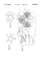
- FIG. 6is a plan view of a circuit board having resistors and conductive paths thereon.
- FIG. 7illustrates an embodiment of a modified form of the circuit board of the present invention.
- FIG. 8illustrates an embodiment of a modified form of the circuit board of the present invention.
- FIG. 9illustrates an embodiment of a modified form of the circuit board of the present invention.
- FIG. 10illustrates an embodiment of a modified form of the circuit board of the present invention.
- FIG. 11is a plan view of an embodiment of the center contacts of the present invention.
- FIG. 12illustrates an embodiment of a modification of the center contacts of the present invention.
- FIG. 13is a detailed view of an embodiment of the electrical paths on the printed circuit board of the present invention.
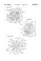
- FIG. 14illustrates a cross-sectional view of an embodiment of the present invention including a collar piece.
- FIG. 15illustrates a perspective view of an embodiment of a collar piece of the present invention.
- FIG. 16illustrates a plan view of an embodiment of a printed circuit board through which the collar piece of the present invention is inserted.
- FIG. 17illustrates a cross-sectional view of another embodiment of a collarless ribbed module.
- FIG. 18illustrates a perspective view partially in cross-section of an embodiment of the collarless ribbed module with metal retaining pin.
- FIG. 19illustrates another perspective view of an embodiment of the metal retaining pin arranged to extend through the ribs and lock into the printed circuit board.
- the present inventionrelates to a joystick pad pointing device which uses a board such as a printed circuit board, glass, paper, ceramic or plastics which have conductive lines and resistive coatings formed on it or embedded or otherwise provided on the surface.
- the boardhas a hole that can be plated on its inner surface and separated with a laser, or by drilling or routing.
- a springfits through the hole at a 900 angle and normally the spring does not make electrical contact with the board when external forces are absent.
- the spring or a sheath around the springis electrically conductive, and the spring or sheath is biased with a voltage. When the spring or sheath is deflected by a user, it bends and makes electrical contact with the conductor within the hole.
- the boardhas electrical contacts (digital) that are closed when an external force is applied. Signals so developed are supplied to a micro controller either or both to wake up the micro-controller and tell it the direction plus speed. Because a digital contact is used, there is not a long analog to digital conversion time.
- a contactis made or increased via the force diverter that causes contact on the analog/digital signal speed/direction interpreter.
- the micro-controllerthen converts this data with the earlier contact and determines various speeds and directions resulting in multiple speeds and multiple directions which are possible.
- the direction possibilitiesare at least two to infinite and speeds may be at least two to infinite.
- the force divertercan be electrically active conductive or can be a pressure transfer point causing a variable closure on a membrane switch.
- the corresponding increase in force on the force divertereither increases the surface area of contact for change in resistance or it changes the absolute point of contact on the analog/digital contact thereby changing the point of the voltage potential. This changes the analog voltage.
- Software in the micro-controllerinterprets such data and sends an output to a relevant receiver which can be connected by a wire or otherwise connected.
- Another novel feature of the pointing deviceis the "fan out" method that the circuit path traces from the resistor, thus, allowing the interleaving of the various traces for different speeds at different angles of displacement.
- FIG. 1is a perspective view illustrating the novel joystick/pressure pad of the invention mounted in a container 10 which has a top surface 11. Cables 12 and 13 extend from the container 10 and join in a cable 14 that is connected to a micro-controller 16 that is associated with a monitor 17 and a keyboard 18.
- FIG. 2is a sectional view of the joystick of the invention wherein the container 10 has a bottom wall 22 and side walls 21 and a top wall 11 formed with an opening 30.
- a spring 27is mounted in a boss 24 formed in the bottom wall 22 and extends upwardly through an opening in a printed circuit board 23 mounted in the container 10 and which has electrical conductive paths 41 and 39 formed on the inner surface of the opening and the printed circuit board 23.
- a force diverter 36is mounted on the spring 27 and at least the outer surface is electrically conductive. It may be made, for example, of low durometer rubber and has a lower conductive surface which can engage printed circuit paths 39 on the printed circuit board 23 when the spring 27 is deflected from its center position.
- the spring 27extends through the opening 30 in the top surface 11, and a stick 31 has an opening 32 in which the spring is received.
- the stick 31has a downwardly extending generally conical portion 33 which joins an outer flat portion 34 that engages the force diverter 36.
- the container 10may be made of non-conductive material and an electrical voltage is applied to the spring 27 by a conductor 6 so as to provide an energizing voltage.
- FIG. 3illustrates the joystick 31 in a deflected from neutral position wherein the outer conductive surface 37 of the force diverter 36 engages the printed circuit conductors 39, and a sheath 28 which is electrically connected to the spring 27 makes electrical contact with one of the conductors 41 in the opening in the printed circuit board 23.
- the center of the force diverter 36may be hollow or filled with a suitable filler such as plastic 38.
- FIG. 4illustrates a slightly modified form of the invention wherein the spring 47 has a first end 48 that is mounted by a sleeve 49 in a bottom plate 46 of the container 10, and the upper end of the spring 47 is received in the hollow insides 92 of a stick 51 which attaches to a bottom plate 53 which engages the force diverter 54.
- the spring 47fits in the opening 92 in the stick 51.
- FIG. 5illustrates a further modification of the invention wherein the force diverter 61 may be made of a flexible substance such as low durometer rubber and has a portion which extends through an opening in the printed circuit board 23 and terminates in an enlarged portion 62.
- a stick 63extends through the opening 30 in the top cover 11 and has a lower flat portion 64 which engages the force diverter 61 to move it to engage the circuit paths 39 on the printed circuit board 23.
- FIG. 6illustrates in plan view the circuit board 23 and includes a first plurality of parallel conductors 121a through 121f mounted on a first segment portion of the board 23.
- a resistive path 126extends at right angles to the conductors 121 and makes electrical contact therewith.
- a second plurality of electrical conductors 122a-122fis formed in another segment of the printed circuit board 123a through 123f, and a resistive path 127 extends at right angles to the conductors 122a through 122f and makes electrical contact therewith.
- a third plurality of conductors 123a through 123fis also mounted on the circuit board 23 in a different segment and are electrically connected to a resistive path 128 which extends at right angles thereto.
- a fourth plurality of conductors 124a through 124fare mounted on another segment of the board 23 and are connected to a resistive path 129 which extends at right angles thereto.
- the spring 47when deflected, engages the conductors 41 on the inside of the opening, and the force diverter 54 engages the printed circuit board 23.
- FIG. 7illustrates another arrangement of the printed circuit board 23 wherein a first plurality of printed circuit paths in the form of segments of a circle 131a-131i are formed in a first segment and are traversed by a resistive path 136.
- a second plurality of curved segments 132a-132iare formed on the printed circuit board 23 and are traversed by a resistive path 137.
- a third plurality of curved segments conducted paths 133a-133iare formed on the board 23 and are traversed by a resistive path 138.
- a fourth plurality of curved segments 134a-134iare mounted on another segment of the printed circuit board 23 and are traversed by a resistive path 139.
- the opening through the printed circuit board 23is formed with four separate conductive paths 101, 102, 103 and 104 which are separated from each other as shown.
- FIG. 8is a modification of the circuit board 23 of FIG. 7 wherein a radially extending printed circuit path 146 is mounted in the space between a first plurality of curved segments 141a-141e and a second plurality of curved segments 142a-142e. Circuit paths 147, 148 and 149 extend from the radial circuit path 146 between the curved segments 141 and 142 as shown.
- Radial circuit paths 151, 156 and 161extend through the gaps between the curved conductive paths 142a-3 and 144a-3 as shown.
- Radial circuit path 151has transverse extending conductive paths 152, 153 and 154 as shown.
- Radial circuit path 156has transverse extending circuit paths 157, 158 and 159 as shown.
- Radial circuit path 161has extending transverse circuit paths 162, 163 and 164 as shown.
- the spring 47is engageable with the conductive segments 101, 102, 103 and 104 when deflected.
- FIG. 9shows another modification of the invention wherein circuit paths 216, 217, 218 and 219 are interwoven between the curved circuit paths such as 213a-213f and 214a-214f and extend at angles which are not perpendicular to radials so as to increase the quantity of speeds that are available in diagonals.
- the interwoven fingers such as 216-219may also be formed between the segments 212a-212f and 213a-213f as well as between the segments 211a-211f and 212a-212f and also between the segments 211a-211f and 214a-214f.
- FIG. 10illustrates a printed circuit board 23 which is formed with additional separated curved segments so as to increase the angular resolution of the device.
- First parallel curved segments 192a-192iare traversed by a resistive path 181.
- Second segments 193a-193iare traversed by a resistive path 182.
- a third plurality of segments 194a-194iare traversed by a resistive path 183.
- a fourth plurality of segments 196a-196iare traversed by a resistive path 184.
- a fifth plurality of radial segments 197a-197iare traversed by a resistive path 186.
- a sixth plurality of radial segments 198a-198iis traversed by a resistive path 187.
- a seventh plurality of conductive paths 199a-199iis traversed by a resistive path 189, and an eighth plurality of conductive paths 201a-201i is traversed by resistive path 191 as shown. This increases the angular resolution of the device by a factor of two over the board shown in FIGS. 6 and 7 for example.
- FIG. 13illustrates in detail the manner of connecting the various electrical conductive paths to an external circuit.
- the conductive portions 101, 102 and 103 and 104 formed in the opening of the printed circuit board 23are connected to terminals as shown which are then connected by conductive paths to terminals such as 309.
- the curved segments 131are each connected to different terminals and are connected by leads such as 302 and 303 to different terminals 304.
- Other segmentsare each connected to different terminals such as 306 which are connected to different remote terminals 304 by the conductive path 5.
- the present inventionprovides a novel joystick which allows many different orientations to be recognized and sent to a control device, as well as allows the amount of deflection of the joystick or pressure pad to be detected, so as to provide a control signal.
- FIG. 14generally illustrates a module unit 500 having several parts.
- a stick 510is encapsulated by an elastomer return container 511 that encapsulates a surface of the module unit 500.
- the elastomer return container 511covers a two-piece rigid cap 512 which covers a conductive elastomer disc 514.
- the two-piece rigid cap 512confines one side of a spring 516.
- the spring 516has a spring extension tab 517 held by a collar 518.
- the collar 518has a radiused internal hole 519.
- a printed circuit board 520has a center hole 521; the collar 518 rests in the center hole 521 of the printed circuit board 521 with the spring 516 in the center of the collar 518.
- the stick 510When the module unit 500 in FIG. 14 has no force applied thereto, the stick 510 is in a static position. A tension force that is exerted by the spring 516 and a tension force exerted by the elastomer return container 511 keeps the stick 510 in a position whereby the conductive elastomer disc 514 does not come in contact with the printed circuit board 520. The conductive elastomer disc 514 rests only on the top surface of the radiused internal hole 519 of the collar 518. The two-piece rigid cap 512 locks a top end of the spring 516; and the collar 518 is locked into the bottom of the center hole 521 of the printed circuit board 520. The spring extension tab 517 is locked into the printed circuit board 520.
- the collar 518has a ramp 522 (as illustrated in FIG. 15) that allows for spinning or rotation of the collar 518 so that the spring 516 is pre-loaded with tension, and the extension tab 517 of the spring 516 falls into a spring slot 525 of the collar 518 (also shown in FIG. 15). This action determines a fixed minimum continuous pre-loaded tension force between the two-piece rigid cap 512 and the collar 518.
- the resulting forceis transferred to the elastomer return container 511 to the two-piece rigid cap 512, and the conductive elastomer disc 514 causes the spring 516 to bend.
- the conductive elastomer disc 514allows the conductive elastomer disc 514 to rotate onto the printed circuit board 520 which has resistors 528 and conductors 530a-530f that radiate outward therefrom (see FIG. 16).
- the spring 516bends such that it stretches across the radiused internal hole 519 of the collar 518.
- the conductive elastomer disc 514causes a change in the electrical resistance on the printed circuit board 520 that may correspond to direction and/or speed.
- the collar 518is conductive and makes contact on the conductive part of the printed circuit board 520 as well as the conductive spring 516.
- the conductive spring 516provides conductivity with the conductive elastomer disc 514 whereby there is a completed electrical path.
- the collar 518has a ramp 522 that has a recess on the top 524 and a spring slot 525.
- the collar 518may also be conductive with the ramp 522 leading into the spring slot 525.
- the purpose of the ramp 522is to pre-load the spring 516 in a constant static position.
- the spring extension tab 517is in a fixed position, and the collar 518 is rotated so that the spring 516 is expanded whereby the spring extension tab 517 falls into the spring slot 525 on the collar 518.
- the other end of the collar 518has a recess on the top 524 to fit and lock into the printed circuit board 520.
- the printed circuit board 520has resistors 528 and conductors 530a-530f. Also provided is a spring tab lock 531. As illustrated in FIG. 16, the printed circuit board 520 with the resistors 528 are placed across the conductors 503a-530f to make a continuous electrical path on a surface of the printed circuit board 520 with a resistance drop depending where the conductive elastomer disc 514 makes contact on the printed circuit board 520. In the center of the printed circuit board 520 is a center hole 521 wherein the recess on the collar 518 on its top 524 press fits to make a rigid fixed support. A spring tab lock 531 locks the spring extension tab 517 in place.
- the module 500consists of the elastomer return container 511 that covers a one-piece rigid cap 632.
- the one-piece rigid cap 632covers a collarless, ribbed, curved disc 634.
- the collarless, ribbed, curved disc 634is fitted through the center hole 521 of the printed circuit board 520.
- the ribbed locking extension 635is provided on the bottom of the collarless, ribbed, curved disc 634.
- the elastomer return container 511covers the one-piece rigid cap 632 that is on top of the collarless, ribbed, curved disc 634 in the neutral position whereby the ribbed locking extension 635 provides the locking, pivoting, and electrical connection to the collarless, ribbed, curved disc 634.
- the collarless, ribbed, curved disc 634has the ribbed locking extension 635 that is inserted into the center hole 521 of the printed circuit board 520. As the surface of the collarless, ribbed, curved disc 634 is deflected, the ribbed locking extension 635 provides tension to return the collarless, ribbed, curved disc 634 back to a neutral position.
- the ribbed locking extension 635is preferably ribbed as opposed to being solid. As best seen in FIG. 18, the ribs of the ribbed locking extension 635 extend transverse to the center hole 521 and are located opposite the center hole 521 from the disc 634. The ribbing is provided such that the extension 635 can be pulled through the center hole 521 of the printed circuit board 520 and have a larger radiating footprint to allow for greater external forces to be applied without the ribbed locking extension 635 being pulled out therefrom.
- the printed circuit board 520has resistors 528 and conductors 530a-530f that make contact with the collarless, ribbed, curved disc 634 causing a variable resistance that may be interpolated into speed and/or position data.
- a conductive trace 640is illustrated that provides electrical connection to the collarless, ribbed, curved disc 634 via the ribbed locking extension 635.
- a metal pin 638is inserted into a center of the ribbed locking extension 635 and the spring tab lock 531.
- the conductive trace 640 that makes electrical and mechanical connection to the collarless, ribbed locking extension 634 via the ribbed locking extension 635is generally illustrated in FIG. 18.
- a metal pin 638can be inserted into the bottom of the center of the ribbed locking extension 635 to provide electrical contact as well as rigid support of the collarless, ribbed, curved disc 634.
- the metal pin 638is inserted into the ribbed locking extension 635 and locked into the spring tab lock 531.
- the metal pin 638is shown in FIG. 19 through the bottom of the ribbed locking extension 635 for electrical connection and locked into the spring tab lock 531.
- mass production of the module unit 500can be provided as well as manufactured for less cost using automated assembly.
- performance of the module unitis enhanced from the features added as shown and described with reference to FIGS. 14-19.
- FIGS. 14-19merely provide an illustration of preferred embodiments of the present invention.
- the ribsmay be of various configurations.
- the number of ribsmay vary, for example, from three to three-hundred.
- the collarmay have several shapes, such as square or oblong.
Landscapes
- Physics & Mathematics (AREA)
- General Physics & Mathematics (AREA)
- Engineering & Computer Science (AREA)
- Automation & Control Theory (AREA)
- Position Input By Displaying (AREA)
- Switches With Compound Operations (AREA)
- Adjustable Resistors (AREA)
Abstract
Description
Claims (17)
Priority Applications (2)
| Application Number | Priority Date | Filing Date | Title |
|---|---|---|---|
| US08/944,282US5949325A (en) | 1995-06-29 | 1997-10-06 | Joystick pointing device |
| US09/071,262US6087925A (en) | 1995-06-29 | 1998-05-01 | Joystick pointing device |
Applications Claiming Priority (2)
| Application Number | Priority Date | Filing Date | Title |
|---|---|---|---|
| US08/496,433US5675309A (en) | 1995-06-29 | 1995-06-29 | Curved disc joystick pointing device |
| US08/944,282US5949325A (en) | 1995-06-29 | 1997-10-06 | Joystick pointing device |
Related Parent Applications (1)
| Application Number | Title | Priority Date | Filing Date |
|---|---|---|---|
| US08/496,433Continuation-In-PartUS5675309A (en) | 1995-06-29 | 1995-06-29 | Curved disc joystick pointing device |
Related Child Applications (1)
| Application Number | Title | Priority Date | Filing Date |
|---|---|---|---|
| US09/071,262Continuation-In-PartUS6087925A (en) | 1995-06-29 | 1998-05-01 | Joystick pointing device |
Publications (1)
| Publication Number | Publication Date |
|---|---|
| US5949325Atrue US5949325A (en) | 1999-09-07 |
Family
ID=23972595
Family Applications (2)
| Application Number | Title | Priority Date | Filing Date |
|---|---|---|---|
| US08/496,433Expired - LifetimeUS5675309A (en) | 1995-06-29 | 1995-06-29 | Curved disc joystick pointing device |
| US08/944,282Expired - LifetimeUS5949325A (en) | 1995-06-29 | 1997-10-06 | Joystick pointing device |
Family Applications Before (1)
| Application Number | Title | Priority Date | Filing Date |
|---|---|---|---|
| US08/496,433Expired - LifetimeUS5675309A (en) | 1995-06-29 | 1995-06-29 | Curved disc joystick pointing device |
Country Status (7)
| Country | Link |
|---|---|
| US (2) | US5675309A (en) |
| EP (1) | EP0762317B1 (en) |
| JP (1) | JPH09120337A (en) |
| AT (1) | ATE212460T1 (en) |
| CA (1) | CA2177118A1 (en) |
| DE (1) | DE69618725T2 (en) |
| TW (1) | TW297110B (en) |
Cited By (36)
| Publication number | Priority date | Publication date | Assignee | Title |
|---|---|---|---|---|
| US6069552A (en)* | 1999-06-02 | 2000-05-30 | Duraswitch Industries, Inc. | Directionally sensitive switch |
| US6236034B1 (en)* | 1998-08-28 | 2001-05-22 | Varatouch Technology Incorporated | Pointing device having segment resistor subtrate |
| US6256012B1 (en)* | 1998-08-25 | 2001-07-03 | Varatouch Technology Incorporated | Uninterrupted curved disc pointing device |
| US6313731B1 (en) | 2000-04-20 | 2001-11-06 | Telefonaktiebolaget L.M. Ericsson | Pressure sensitive direction switches |
| US6313826B1 (en)* | 1998-04-07 | 2001-11-06 | Varatouch Technology Incorporated | Pointing device with non-spring return mechanism |
| US6380498B1 (en)* | 1999-07-30 | 2002-04-30 | Shin Jiuh Corp. | Position control device |
| WO2002035513A1 (en)* | 2000-10-25 | 2002-05-02 | Motorola Inc. | Multi-function key assembly for an electronic device |
| US6420956B1 (en)* | 2000-07-31 | 2002-07-16 | Alps Electric Co., Ltd. | Detection device in which output varies with amount by which elastically deformable contact element is pressed |
| WO2002056328A1 (en) | 2000-12-21 | 2002-07-18 | Ict, Inc. | Inductive joysticka |
| US6496178B1 (en) | 1997-09-29 | 2002-12-17 | Varatouch Technology Incorporated | Pointing device |
| US6580414B1 (en)* | 1998-10-19 | 2003-06-17 | Gerhard Wergen | Method for transferring characters especially to a computer and an input device which functions according to this method |
| US6653579B2 (en)* | 2000-10-05 | 2003-11-25 | Matsushita Electrical Industrial Co., Ltd. | Multi-directional input joystick switch |
| US20040027231A1 (en)* | 2001-07-23 | 2004-02-12 | Hiroto Inoue | Multi-directional input and electronic equipment using the device |
| US6717569B1 (en) | 2000-02-29 | 2004-04-06 | Microsoft Corporation | Control device with enhanced control aspects and method for programming same |
| US6724198B2 (en) | 2000-12-21 | 2004-04-20 | G. Burnell Hohl | Inductive sensory apparatus |
| US6903724B2 (en)* | 2000-12-08 | 2005-06-07 | Motorola, Inc. | Handheld communications devices with joysticks and switch contact layouts therefor |
| US6937227B2 (en) | 2003-07-14 | 2005-08-30 | Iowa State University Research Foundation, Inc. | Hand-held pointing device |
| US20050274595A1 (en)* | 2004-06-10 | 2005-12-15 | Pekka Pihlaja | Key |
| US20060131156A1 (en)* | 2002-06-24 | 2006-06-22 | Oliver Voelckers | Device for detecting a mechanical actuation of an input element by using digital technology, and method for processing and converting the digital input signal into commands for controlling a load |
| US20060261923A1 (en)* | 1999-05-25 | 2006-11-23 | Schrum Allan E | Resilient material potentiometer |
| US20070061126A1 (en)* | 2005-09-01 | 2007-03-15 | Anthony Russo | System for and method of emulating electronic input devices |
| US20070125628A1 (en)* | 2005-12-05 | 2007-06-07 | Lg Electronics Inc. | Input device and mobile terminal having the same |
| US20070235316A1 (en)* | 2006-04-10 | 2007-10-11 | Hon Hai Precision Ind. Co., Ltd. | Multi-directional switch and multi-directional operating device using the same |
| US20070271048A1 (en)* | 2006-02-10 | 2007-11-22 | David Feist | Systems using variable resistance zones and stops for generating inputs to an electronic device |
| US20080251368A1 (en)* | 2007-04-12 | 2008-10-16 | Sony Ericsson Mobile Communications Ab | Input device |
| US20080251365A1 (en)* | 2007-04-12 | 2008-10-16 | Sony Ericsson Mobile Communications Ab | Input device |
| US7474772B2 (en) | 2003-06-25 | 2009-01-06 | Atrua Technologies, Inc. | System and method for a miniature user input device |
| US7587072B2 (en) | 2003-08-22 | 2009-09-08 | Authentec, Inc. | System for and method of generating rotational inputs |
| US8421890B2 (en) | 2010-01-15 | 2013-04-16 | Picofield Technologies, Inc. | Electronic imager using an impedance sensor grid array and method of making |
| US8593428B1 (en)* | 2007-06-22 | 2013-11-26 | Cypress Semiconductor Corporation | Radial track-pad system and method |
| US8791792B2 (en) | 2010-01-15 | 2014-07-29 | Idex Asa | Electronic imager using an impedance sensor grid array mounted on or about a switch and method of making |
| US8866347B2 (en) | 2010-01-15 | 2014-10-21 | Idex Asa | Biometric image sensing |
| US9235274B1 (en) | 2006-07-25 | 2016-01-12 | Apple Inc. | Low-profile or ultra-thin navigation pointing or haptic feedback device |
| US9798917B2 (en) | 2012-04-10 | 2017-10-24 | Idex Asa | Biometric sensing |
| EP3634591A1 (en)* | 2017-06-07 | 2020-04-15 | Sony Interactive Entertainment Inc. | Input method and apparatus |
| US20220376584A1 (en)* | 2021-05-20 | 2022-11-24 | Black & Decker Inc. | Variable-speed trigger switch having a conductive elastomer |
Families Citing this family (28)
| Publication number | Priority date | Publication date | Assignee | Title |
|---|---|---|---|---|
| US6285356B1 (en)* | 1999-02-19 | 2001-09-04 | Brad A. Armstrong | Displacement joystick with compression-sensitive sensors |
| US6906700B1 (en) | 1992-03-05 | 2005-06-14 | Anascape | 3D controller with vibration |
| US6222525B1 (en) | 1992-03-05 | 2001-04-24 | Brad A. Armstrong | Image controllers with sheet connected sensors |
| US6087925A (en)* | 1995-06-29 | 2000-07-11 | Devolpi; Dean | Joystick pointing device |
| US5675309A (en)* | 1995-06-29 | 1997-10-07 | Devolpi Dean | Curved disc joystick pointing device |
| JPH09161617A (en)* | 1995-11-30 | 1997-06-20 | Sega Enterp Ltd | Switch device |
| US8674932B2 (en) | 1996-07-05 | 2014-03-18 | Anascape, Ltd. | Image controller |
| US6115028A (en)* | 1996-08-22 | 2000-09-05 | Silicon Graphics, Inc. | Three dimensional input system using tilt |
| US5818324A (en)* | 1996-11-13 | 1998-10-06 | Resistance Technology, Inc. | Wire coil potentiometer wiper |
| DE19732890A1 (en)* | 1997-07-30 | 1999-02-18 | Still & Saxby Sarl | Drawbar head for a drawbar-controlled industrial truck |
| US6252582B1 (en) | 1998-08-11 | 2001-06-26 | Varatouch Technology Incorporated | Ergonomic pointing device |
| EP1019792B1 (en)* | 1997-09-29 | 2003-05-14 | Varatouch Technology Incorporated | Pointing device with integrated switch |
| US5912612A (en)* | 1997-10-14 | 1999-06-15 | Devolpi; Dean R. | Multi-speed multi-direction analog pointing device |
| US6279048B1 (en)* | 1997-11-14 | 2001-08-21 | Lucent Technologies, Inc. | System wake-up based on joystick movement |
| US6243077B1 (en) | 1998-11-18 | 2001-06-05 | Boourns, Inc. | Sensor and circuit architecture for three axis strain gauge pointing device and force transducer |
| US6404323B1 (en)* | 1999-05-25 | 2002-06-11 | Varatouch Technology Incorporated | Variable resistance devices and methods |
| EP1058177A1 (en)* | 1999-06-04 | 2000-12-06 | Alps Electric Co., Ltd. | Input device for game machine |
| US6573465B1 (en)* | 2002-01-29 | 2003-06-03 | Connector Set Limited Partnership | Contact switch |
| US6630635B1 (en)* | 2002-01-29 | 2003-10-07 | Connector Set Limited Partnership | Universal contact switch |
| US20050231475A1 (en)* | 2004-04-14 | 2005-10-20 | Sony Corporation | Combined joy pad and joystick controller |
| US7831070B1 (en) | 2005-02-18 | 2010-11-09 | Authentec, Inc. | Dynamic finger detection mechanism for a fingerprint sensor |
| JP4830580B2 (en)* | 2006-03-29 | 2011-12-07 | 株式会社デンソー | Operating device |
| US8526161B2 (en)* | 2010-04-19 | 2013-09-03 | Apple Inc. | Button structures for electronic devices |
| CN102157286A (en)* | 2010-04-19 | 2011-08-17 | 苹果公司 | Output and input system for electronic apparatus |
| US8638203B2 (en)* | 2011-01-18 | 2014-01-28 | Howard Beuter Inc. | Fifth wheel alarm system |
| US20140083833A1 (en)* | 2012-09-26 | 2014-03-27 | ION Audio, LLC | Miniaturized joystick assembly |
| US9542009B2 (en)* | 2013-03-15 | 2017-01-10 | Microchip Technology Incorporated | Knob based gesture system |
| JP7353912B2 (en)* | 2019-10-17 | 2023-10-02 | 任天堂株式会社 | Input devices, game controllers, information processing devices |
Citations (50)
| Publication number | Priority date | Publication date | Assignee | Title |
|---|---|---|---|---|
| US3193628A (en)* | 1963-02-26 | 1965-07-06 | Gen Motors Corp | Multiple circuit controller switch with elongated flexible contact member |
| US3531754A (en)* | 1969-03-17 | 1970-09-29 | Bourns Inc | Potentiometer |
| US3533043A (en)* | 1968-11-21 | 1970-10-06 | Allen Bradley Co | Adjustable electronic component |
| US3576514A (en)* | 1969-01-02 | 1971-04-27 | Bourns Inc | Potentiometer with embedded reversely bent contact wires |
| US3629775A (en)* | 1970-06-19 | 1971-12-21 | Gulf & Western Industries | Stereo balance and fader potentiometer |
| US3652970A (en)* | 1971-02-25 | 1972-03-28 | Spectrol Electronics Corp | Variable resistor having an improved wiper member |
| US3795882A (en)* | 1972-05-06 | 1974-03-05 | Teikoku Tsushin Kogyo Kk | Coordinated control device for variable resistors |
| US3900817A (en)* | 1973-12-10 | 1975-08-19 | Xerox Corp | Spherical potentiometer with ball contact means |
| US3905097A (en)* | 1973-10-19 | 1975-09-16 | Trw Inc | Method of making plural potentiometer body |
| US3964011A (en)* | 1974-03-18 | 1976-06-15 | North American Philips Corporation | Single turn variable resistance device having a split shaft rotor |
| US4020444A (en)* | 1975-02-27 | 1977-04-26 | Fernsteuergerate, Kurt Oelsch Kg | Slider arrangement for potentiometers or the like |
| US4026048A (en)* | 1975-12-31 | 1977-05-31 | Douglas Dynamics Corporation | Multiple circuit control |
| US4095210A (en)* | 1975-12-19 | 1978-06-13 | North American Philips Corporation | Helical coil spring wiper potentiometer contact device |
| US4225845A (en)* | 1978-08-30 | 1980-09-30 | North American Philips Corporation | Open frame single turn potentiometer with helical coil spring wiper and resilient member |
| US4297671A (en)* | 1980-06-11 | 1981-10-27 | Cts Corporation | Tandem insert molded electrical controls and process for producing same |
| US4352084A (en)* | 1980-11-13 | 1982-09-28 | Eeco Incorporated | Variable resistor disk assembly |
| US4355293A (en)* | 1979-10-22 | 1982-10-19 | The Bendix Corporation | Electrical resistance apparatus having integral shorting protection |
| US4361824A (en)* | 1981-08-10 | 1982-11-30 | Honeywell Inc. | Slidewire wiper contact |
| EP0089295A2 (en)* | 1982-03-17 | 1983-09-21 | Sfernice Societe Francaise De L'electro-Resistance | Electronic guidance device |
| US4414438A (en)* | 1982-06-04 | 1983-11-08 | International Jensen Incorporated | Video game controller |
| US4433217A (en)* | 1982-08-16 | 1984-02-21 | Koala Technologies Corporation | Hand controller multiple circuit switch |
| US4439648A (en)* | 1982-07-28 | 1984-03-27 | Coleco Industries, Inc. | Joystick-type controller |
| US4500867A (en)* | 1982-01-13 | 1985-02-19 | Nec Kansai, Ltd. | Joystick controller using magnetosensitive elements with bias magnets |
| US4511769A (en)* | 1982-08-20 | 1985-04-16 | U.S. Philips Corporation | Multi-path interrupter device |
| US4533899A (en)* | 1982-12-23 | 1985-08-06 | Akermans Verkstad Ab | Joystick controller with improved motion control with plate having bevelled flat edges that correspond to planes of maneuverability |
| US4555960A (en)* | 1983-03-23 | 1985-12-03 | Cae Electronics, Ltd. | Six degree of freedom hand controller |
| US4590339A (en)* | 1985-02-19 | 1986-05-20 | Gravis Computer Peripherals Inc. | Joystick |
| US4621250A (en)* | 1984-02-28 | 1986-11-04 | Renix Electronique | Rotary potentiometer, particularly for measuring angular position |
| US4687200A (en)* | 1983-08-05 | 1987-08-18 | Nintendo Co., Ltd. | Multi-directional switch |
| US4733214A (en)* | 1983-05-23 | 1988-03-22 | Andresen Herman J | Multi-directional controller having resiliently biased cam and cam follower for tactile feedback |
| US4739128A (en)* | 1986-11-10 | 1988-04-19 | American Telephone And Telegraph Company, At&T Bell Laboratories | Thumb-controlled, hand-held joystick |
| US4748441A (en)* | 1986-09-17 | 1988-05-31 | Brzezinski Stephen R M | Multiple function control member |
| US4758692A (en)* | 1987-05-19 | 1988-07-19 | Otto Engineering, Inc. | Joystick type control device |
| US4769517A (en)* | 1987-04-13 | 1988-09-06 | Swinney Carl M | Joystick switch assembly |
| EP0286388A1 (en)* | 1987-04-06 | 1988-10-12 | Gould Electronics Limited | Electrical control device |
| US4784008A (en)* | 1986-05-22 | 1988-11-15 | La Telemecanique Electrique | Analogue manipulator with preferential orientations |
| US4795952A (en)* | 1986-05-12 | 1989-01-03 | The Warner & Swasey Company | Joystick for three axis control of a powered element |
| US4810994A (en)* | 1986-05-02 | 1989-03-07 | Bourns, Inc. | Spiral wire contact assembly for variable resistor |
| US4849583A (en)* | 1987-07-28 | 1989-07-18 | Wilhelm Meyer Gmbh & Co. Kg | Electrical joy stick control device |
| US4896003A (en)* | 1989-06-30 | 1990-01-23 | Hsieh Man Ching | Multi-position electrical switch |
| US5068498A (en)* | 1990-08-14 | 1991-11-26 | Wico Distribution Corp. | Joystick for mounting on dual-width panels |
| EP0640937A1 (en)* | 1993-08-30 | 1995-03-01 | Hosiden Corporation | Input control device |
| US5406040A (en)* | 1993-12-09 | 1995-04-11 | Wico Corporation | Joystick with improved actuator |
| US5473126A (en)* | 1994-01-31 | 1995-12-05 | Wu; Donald | Joystick switch assembly |
| US5488206A (en)* | 1994-01-31 | 1996-01-30 | Wu; Donald | Joystick switch assembly |
| US5498843A (en)* | 1992-06-30 | 1996-03-12 | Sega Enterprises, Ltd. | Control key multiple electrical contact switching device |
| US5510812A (en)* | 1994-04-22 | 1996-04-23 | Hasbro, Inc. | Piezoresistive input device |
| US5515044A (en)* | 1994-04-18 | 1996-05-07 | Sensormatic Electronics Corporation | Controller apparatus using force sensing resistors |
| US5541622A (en)* | 1990-07-24 | 1996-07-30 | Incontrol Solutions, Inc. | Miniature isometric joystick |
| US5675309A (en)* | 1995-06-29 | 1997-10-07 | Devolpi Dean | Curved disc joystick pointing device |
Family Cites Families (3)
| Publication number | Priority date | Publication date | Assignee | Title |
|---|---|---|---|---|
| US4685678A (en)* | 1982-08-13 | 1987-08-11 | Bally Manufacturing Corporation | Position transducer system for a joystick |
| US4864272A (en)* | 1987-05-28 | 1989-09-05 | Suncom, Inc. | Joystick controller |
| US4857881A (en)* | 1988-07-08 | 1989-08-15 | Hayes Technology | Joystick with spring disconnect |
- 1995
- 1995-06-29USUS08/496,433patent/US5675309A/ennot_activeExpired - Lifetime
- 1996
- 1996-05-15ATAT96107795Tpatent/ATE212460T1/ennot_activeIP Right Cessation
- 1996-05-15DEDE69618725Tpatent/DE69618725T2/ennot_activeExpired - Lifetime
- 1996-05-15EPEP96107795Apatent/EP0762317B1/ennot_activeExpired - Lifetime
- 1996-05-22CACA002177118Apatent/CA2177118A1/ennot_activeAbandoned
- 1996-06-04TWTW085106657Apatent/TW297110B/zhactive
- 1996-06-28JPJP8186904Apatent/JPH09120337A/enactivePending
- 1997
- 1997-10-06USUS08/944,282patent/US5949325A/ennot_activeExpired - Lifetime
Patent Citations (53)
| Publication number | Priority date | Publication date | Assignee | Title |
|---|---|---|---|---|
| US3193628A (en)* | 1963-02-26 | 1965-07-06 | Gen Motors Corp | Multiple circuit controller switch with elongated flexible contact member |
| US3533043A (en)* | 1968-11-21 | 1970-10-06 | Allen Bradley Co | Adjustable electronic component |
| US3576514A (en)* | 1969-01-02 | 1971-04-27 | Bourns Inc | Potentiometer with embedded reversely bent contact wires |
| US3531754A (en)* | 1969-03-17 | 1970-09-29 | Bourns Inc | Potentiometer |
| US3629775A (en)* | 1970-06-19 | 1971-12-21 | Gulf & Western Industries | Stereo balance and fader potentiometer |
| US3652970A (en)* | 1971-02-25 | 1972-03-28 | Spectrol Electronics Corp | Variable resistor having an improved wiper member |
| US3795882A (en)* | 1972-05-06 | 1974-03-05 | Teikoku Tsushin Kogyo Kk | Coordinated control device for variable resistors |
| US3905097A (en)* | 1973-10-19 | 1975-09-16 | Trw Inc | Method of making plural potentiometer body |
| US3900817A (en)* | 1973-12-10 | 1975-08-19 | Xerox Corp | Spherical potentiometer with ball contact means |
| US3964011A (en)* | 1974-03-18 | 1976-06-15 | North American Philips Corporation | Single turn variable resistance device having a split shaft rotor |
| US4020444A (en)* | 1975-02-27 | 1977-04-26 | Fernsteuergerate, Kurt Oelsch Kg | Slider arrangement for potentiometers or the like |
| US4095210A (en)* | 1975-12-19 | 1978-06-13 | North American Philips Corporation | Helical coil spring wiper potentiometer contact device |
| US4121188A (en)* | 1975-12-19 | 1978-10-17 | North American Philips Corporation | Closed frame single turn potentiometer with helical coil spring wiper adjustable through substrate |
| US4158831A (en)* | 1975-12-19 | 1979-06-19 | North American Philips Corporation | Single turn potentiometer with helical coil spring wiper |
| US4026048A (en)* | 1975-12-31 | 1977-05-31 | Douglas Dynamics Corporation | Multiple circuit control |
| US4225845A (en)* | 1978-08-30 | 1980-09-30 | North American Philips Corporation | Open frame single turn potentiometer with helical coil spring wiper and resilient member |
| US4355293A (en)* | 1979-10-22 | 1982-10-19 | The Bendix Corporation | Electrical resistance apparatus having integral shorting protection |
| US4355293B1 (en)* | 1979-10-22 | 1985-09-03 | ||
| US4297671A (en)* | 1980-06-11 | 1981-10-27 | Cts Corporation | Tandem insert molded electrical controls and process for producing same |
| US4352084A (en)* | 1980-11-13 | 1982-09-28 | Eeco Incorporated | Variable resistor disk assembly |
| US4361824A (en)* | 1981-08-10 | 1982-11-30 | Honeywell Inc. | Slidewire wiper contact |
| US4500867A (en)* | 1982-01-13 | 1985-02-19 | Nec Kansai, Ltd. | Joystick controller using magnetosensitive elements with bias magnets |
| EP0089295A2 (en)* | 1982-03-17 | 1983-09-21 | Sfernice Societe Francaise De L'electro-Resistance | Electronic guidance device |
| US4414438A (en)* | 1982-06-04 | 1983-11-08 | International Jensen Incorporated | Video game controller |
| US4439648A (en)* | 1982-07-28 | 1984-03-27 | Coleco Industries, Inc. | Joystick-type controller |
| US4433217A (en)* | 1982-08-16 | 1984-02-21 | Koala Technologies Corporation | Hand controller multiple circuit switch |
| US4511769A (en)* | 1982-08-20 | 1985-04-16 | U.S. Philips Corporation | Multi-path interrupter device |
| US4533899A (en)* | 1982-12-23 | 1985-08-06 | Akermans Verkstad Ab | Joystick controller with improved motion control with plate having bevelled flat edges that correspond to planes of maneuverability |
| US4555960A (en)* | 1983-03-23 | 1985-12-03 | Cae Electronics, Ltd. | Six degree of freedom hand controller |
| US4733214A (en)* | 1983-05-23 | 1988-03-22 | Andresen Herman J | Multi-directional controller having resiliently biased cam and cam follower for tactile feedback |
| US4687200A (en)* | 1983-08-05 | 1987-08-18 | Nintendo Co., Ltd. | Multi-directional switch |
| US4621250A (en)* | 1984-02-28 | 1986-11-04 | Renix Electronique | Rotary potentiometer, particularly for measuring angular position |
| US4590339A (en)* | 1985-02-19 | 1986-05-20 | Gravis Computer Peripherals Inc. | Joystick |
| US4810994A (en)* | 1986-05-02 | 1989-03-07 | Bourns, Inc. | Spiral wire contact assembly for variable resistor |
| US4795952A (en)* | 1986-05-12 | 1989-01-03 | The Warner & Swasey Company | Joystick for three axis control of a powered element |
| US4784008A (en)* | 1986-05-22 | 1988-11-15 | La Telemecanique Electrique | Analogue manipulator with preferential orientations |
| US4748441A (en)* | 1986-09-17 | 1988-05-31 | Brzezinski Stephen R M | Multiple function control member |
| US4739128A (en)* | 1986-11-10 | 1988-04-19 | American Telephone And Telegraph Company, At&T Bell Laboratories | Thumb-controlled, hand-held joystick |
| EP0286388A1 (en)* | 1987-04-06 | 1988-10-12 | Gould Electronics Limited | Electrical control device |
| US4769517A (en)* | 1987-04-13 | 1988-09-06 | Swinney Carl M | Joystick switch assembly |
| US4758692A (en)* | 1987-05-19 | 1988-07-19 | Otto Engineering, Inc. | Joystick type control device |
| US4849583A (en)* | 1987-07-28 | 1989-07-18 | Wilhelm Meyer Gmbh & Co. Kg | Electrical joy stick control device |
| US4896003A (en)* | 1989-06-30 | 1990-01-23 | Hsieh Man Ching | Multi-position electrical switch |
| US5541622A (en)* | 1990-07-24 | 1996-07-30 | Incontrol Solutions, Inc. | Miniature isometric joystick |
| US5068498A (en)* | 1990-08-14 | 1991-11-26 | Wico Distribution Corp. | Joystick for mounting on dual-width panels |
| US5498843A (en)* | 1992-06-30 | 1996-03-12 | Sega Enterprises, Ltd. | Control key multiple electrical contact switching device |
| EP0640937A1 (en)* | 1993-08-30 | 1995-03-01 | Hosiden Corporation | Input control device |
| US5406040A (en)* | 1993-12-09 | 1995-04-11 | Wico Corporation | Joystick with improved actuator |
| US5488206A (en)* | 1994-01-31 | 1996-01-30 | Wu; Donald | Joystick switch assembly |
| US5473126A (en)* | 1994-01-31 | 1995-12-05 | Wu; Donald | Joystick switch assembly |
| US5515044A (en)* | 1994-04-18 | 1996-05-07 | Sensormatic Electronics Corporation | Controller apparatus using force sensing resistors |
| US5510812A (en)* | 1994-04-22 | 1996-04-23 | Hasbro, Inc. | Piezoresistive input device |
| US5675309A (en)* | 1995-06-29 | 1997-10-07 | Devolpi Dean | Curved disc joystick pointing device |
Cited By (65)
| Publication number | Priority date | Publication date | Assignee | Title |
|---|---|---|---|---|
| US6496178B1 (en) | 1997-09-29 | 2002-12-17 | Varatouch Technology Incorporated | Pointing device |
| US6313826B1 (en)* | 1998-04-07 | 2001-11-06 | Varatouch Technology Incorporated | Pointing device with non-spring return mechanism |
| US6256012B1 (en)* | 1998-08-25 | 2001-07-03 | Varatouch Technology Incorporated | Uninterrupted curved disc pointing device |
| US6236034B1 (en)* | 1998-08-28 | 2001-05-22 | Varatouch Technology Incorporated | Pointing device having segment resistor subtrate |
| US6580414B1 (en)* | 1998-10-19 | 2003-06-17 | Gerhard Wergen | Method for transferring characters especially to a computer and an input device which functions according to this method |
| US20070063810A1 (en)* | 1999-05-25 | 2007-03-22 | Schrum Allan E | Resilient material variable resistor |
| US20060261923A1 (en)* | 1999-05-25 | 2006-11-23 | Schrum Allan E | Resilient material potentiometer |
| US7788799B2 (en) | 1999-05-25 | 2010-09-07 | Authentec, Inc. | Linear resilient material variable resistor |
| US20070139156A1 (en)* | 1999-05-25 | 2007-06-21 | Schrum Allan E | Resilient material variable resistor |
| US7629871B2 (en) | 1999-05-25 | 2009-12-08 | Authentec, Inc. | Resilient material variable resistor |
| US20070188294A1 (en)* | 1999-05-25 | 2007-08-16 | Schrum Allan E | Resilient material potentiometer |
| US7391296B2 (en) | 1999-05-25 | 2008-06-24 | Varatouch Technology Incorporated | Resilient material potentiometer |
| US20070194877A1 (en)* | 1999-05-25 | 2007-08-23 | Schrum Allan E | Resilient material potentiometer |
| US20070063811A1 (en)* | 1999-05-25 | 2007-03-22 | Schrum Allan E | Linear resilient material variable resistor |
| US7190251B2 (en) | 1999-05-25 | 2007-03-13 | Varatouch Technology Incorporated | Variable resistance devices and methods |
| US6069552A (en)* | 1999-06-02 | 2000-05-30 | Duraswitch Industries, Inc. | Directionally sensitive switch |
| WO2000074084A1 (en)* | 1999-06-02 | 2000-12-07 | Duraswitch Industries, Inc. | Directionally sensitive switch |
| US6380498B1 (en)* | 1999-07-30 | 2002-04-30 | Shin Jiuh Corp. | Position control device |
| US6717569B1 (en) | 2000-02-29 | 2004-04-06 | Microsoft Corporation | Control device with enhanced control aspects and method for programming same |
| US6437682B1 (en) | 2000-04-20 | 2002-08-20 | Ericsson Inc. | Pressure sensitive direction switches |
| US6313731B1 (en) | 2000-04-20 | 2001-11-06 | Telefonaktiebolaget L.M. Ericsson | Pressure sensitive direction switches |
| EP1178296A3 (en)* | 2000-07-31 | 2004-03-31 | Alps Electric Co., Ltd. | Detection device with resistive variation in accordance with pressing force |
| US6420956B1 (en)* | 2000-07-31 | 2002-07-16 | Alps Electric Co., Ltd. | Detection device in which output varies with amount by which elastically deformable contact element is pressed |
| US6653579B2 (en)* | 2000-10-05 | 2003-11-25 | Matsushita Electrical Industrial Co., Ltd. | Multi-directional input joystick switch |
| WO2002035513A1 (en)* | 2000-10-25 | 2002-05-02 | Motorola Inc. | Multi-function key assembly for an electronic device |
| US6441753B1 (en) | 2000-10-25 | 2002-08-27 | Motorola, Inc. | Multi-function key assembly for an electronic device |
| US6903724B2 (en)* | 2000-12-08 | 2005-06-07 | Motorola, Inc. | Handheld communications devices with joysticks and switch contact layouts therefor |
| US6724198B2 (en) | 2000-12-21 | 2004-04-20 | G. Burnell Hohl | Inductive sensory apparatus |
| WO2002056328A1 (en) | 2000-12-21 | 2002-07-18 | Ict, Inc. | Inductive joysticka |
| US6445311B1 (en) | 2000-12-21 | 2002-09-03 | G. Burnell Hohl | Inductive joystick |
| US20040027231A1 (en)* | 2001-07-23 | 2004-02-12 | Hiroto Inoue | Multi-directional input and electronic equipment using the device |
| US20060131156A1 (en)* | 2002-06-24 | 2006-06-22 | Oliver Voelckers | Device for detecting a mechanical actuation of an input element by using digital technology, and method for processing and converting the digital input signal into commands for controlling a load |
| US7534973B2 (en)* | 2002-06-24 | 2009-05-19 | Oliver Voelckers | Device for detecting a mechanical actuation of an input element by using digital technology, and method for processing and converting the digital input signal into commands for controlling a load |
| US7474772B2 (en) | 2003-06-25 | 2009-01-06 | Atrua Technologies, Inc. | System and method for a miniature user input device |
| US6937227B2 (en) | 2003-07-14 | 2005-08-30 | Iowa State University Research Foundation, Inc. | Hand-held pointing device |
| US7587072B2 (en) | 2003-08-22 | 2009-09-08 | Authentec, Inc. | System for and method of generating rotational inputs |
| US20050274595A1 (en)* | 2004-06-10 | 2005-12-15 | Pekka Pihlaja | Key |
| US7060923B2 (en)* | 2004-06-10 | 2006-06-13 | Nokia Corporation | Key |
| US20070061126A1 (en)* | 2005-09-01 | 2007-03-15 | Anthony Russo | System for and method of emulating electronic input devices |
| US20070125628A1 (en)* | 2005-12-05 | 2007-06-07 | Lg Electronics Inc. | Input device and mobile terminal having the same |
| US7579560B2 (en)* | 2005-12-05 | 2009-08-25 | Lg Electronics Inc. | Input device and mobile terminal having the same |
| US20070271048A1 (en)* | 2006-02-10 | 2007-11-22 | David Feist | Systems using variable resistance zones and stops for generating inputs to an electronic device |
| US7684953B2 (en) | 2006-02-10 | 2010-03-23 | Authentec, Inc. | Systems using variable resistance zones and stops for generating inputs to an electronic device |
| US20070235316A1 (en)* | 2006-04-10 | 2007-10-11 | Hon Hai Precision Ind. Co., Ltd. | Multi-directional switch and multi-directional operating device using the same |
| US7820925B2 (en)* | 2006-04-10 | 2010-10-26 | Hon Hai Precision Ind. Co., Ltd | Multi-directional switch and multi-directional operating device using the same |
| US9235274B1 (en) | 2006-07-25 | 2016-01-12 | Apple Inc. | Low-profile or ultra-thin navigation pointing or haptic feedback device |
| US20080251365A1 (en)* | 2007-04-12 | 2008-10-16 | Sony Ericsson Mobile Communications Ab | Input device |
| US20080251368A1 (en)* | 2007-04-12 | 2008-10-16 | Sony Ericsson Mobile Communications Ab | Input device |
| WO2008125152A1 (en)* | 2007-04-12 | 2008-10-23 | Sony Ericsson Mobile Communications Ab | Input device |
| US8593428B1 (en)* | 2007-06-22 | 2013-11-26 | Cypress Semiconductor Corporation | Radial track-pad system and method |
| US9600704B2 (en) | 2010-01-15 | 2017-03-21 | Idex Asa | Electronic imager using an impedance sensor grid array and method of making |
| US10115001B2 (en) | 2010-01-15 | 2018-10-30 | Idex Asa | Biometric image sensing |
| US8791792B2 (en) | 2010-01-15 | 2014-07-29 | Idex Asa | Electronic imager using an impedance sensor grid array mounted on or about a switch and method of making |
| US9268988B2 (en) | 2010-01-15 | 2016-02-23 | Idex Asa | Biometric image sensing |
| US8421890B2 (en) | 2010-01-15 | 2013-04-16 | Picofield Technologies, Inc. | Electronic imager using an impedance sensor grid array and method of making |
| US9659208B2 (en) | 2010-01-15 | 2017-05-23 | Idex Asa | Biometric image sensing |
| US11080504B2 (en) | 2010-01-15 | 2021-08-03 | Idex Biometrics Asa | Biometric image sensing |
| US10592719B2 (en) | 2010-01-15 | 2020-03-17 | Idex Biometrics Asa | Biometric image sensing |
| US8866347B2 (en) | 2010-01-15 | 2014-10-21 | Idex Asa | Biometric image sensing |
| US10114497B2 (en) | 2012-04-10 | 2018-10-30 | Idex Asa | Biometric sensing |
| US10101851B2 (en) | 2012-04-10 | 2018-10-16 | Idex Asa | Display with integrated touch screen and fingerprint sensor |
| US10088939B2 (en) | 2012-04-10 | 2018-10-02 | Idex Asa | Biometric sensing |
| US9798917B2 (en) | 2012-04-10 | 2017-10-24 | Idex Asa | Biometric sensing |
| EP3634591A1 (en)* | 2017-06-07 | 2020-04-15 | Sony Interactive Entertainment Inc. | Input method and apparatus |
| US20220376584A1 (en)* | 2021-05-20 | 2022-11-24 | Black & Decker Inc. | Variable-speed trigger switch having a conductive elastomer |
Also Published As
| Publication number | Publication date |
|---|---|
| ATE212460T1 (en) | 2002-02-15 |
| JPH09120337A (en) | 1997-05-06 |
| US5675309A (en) | 1997-10-07 |
| EP0762317B1 (en) | 2002-01-23 |
| DE69618725D1 (en) | 2002-03-14 |
| DE69618725T2 (en) | 2002-10-31 |
| CA2177118A1 (en) | 1996-12-30 |
| TW297110B (en) | 1997-02-01 |
| EP0762317A1 (en) | 1997-03-12 |
Similar Documents
| Publication | Publication Date | Title |
|---|---|---|
| US5949325A (en) | Joystick pointing device | |
| US6087925A (en) | Joystick pointing device | |
| US6256012B1 (en) | Uninterrupted curved disc pointing device | |
| US6313826B1 (en) | Pointing device with non-spring return mechanism | |
| CA1249320A (en) | Hand operable controller | |
| US5510812A (en) | Piezoresistive input device | |
| US6304247B1 (en) | Piezoelectric stick pointing device | |
| US5689285A (en) | Joystick with membrane sensor | |
| US5287089A (en) | Hand manipulatable computer input device | |
| EP0640937B1 (en) | Input control device | |
| EP0838776A2 (en) | Apparatus for sensing user input | |
| US6654005B2 (en) | Low profile joy stick and switch | |
| US6369692B1 (en) | Directionally sensitive switch | |
| US20060033708A1 (en) | Image controller | |
| US7199314B2 (en) | Joystick and switch | |
| US4501939A (en) | Digital joystick controller | |
| US6181323B1 (en) | Multidirectional controller and multidirectional controlling device using the same | |
| US6236034B1 (en) | Pointing device having segment resistor subtrate | |
| US6420956B1 (en) | Detection device in which output varies with amount by which elastically deformable contact element is pressed | |
| US6107993A (en) | Keystick miniature pointing device | |
| US20030066739A1 (en) | Controller with tactile feedback | |
| US7239248B2 (en) | Level/position sensor and related electronic circuitry for interactive toy | |
| EP0986022A2 (en) | A pointing stick having integral control circuitry | |
| JP3954776B2 (en) | Input device | |
| EP0899752A1 (en) | Rotary movement transducer |
Legal Events
| Date | Code | Title | Description |
|---|---|---|---|
| AS | Assignment | Owner name:VARATOUCH TECHNOLOGY INC., CALIFORNIA Free format text:ASSIGNMENT OF ASSIGNORS INTEREST;ASSIGNOR:DEVOLPI, DEAN;REEL/FRAME:009088/0001 Effective date:19980302 | |
| REMI | Maintenance fee reminder mailed | ||
| REIN | Reinstatement after maintenance fee payment confirmed | ||
| FP | Lapsed due to failure to pay maintenance fee | Effective date:20030907 | |
| FEPP | Fee payment procedure | Free format text:PETITION RELATED TO MAINTENANCE FEES FILED (ORIGINAL EVENT CODE: PMFP); ENTITY STATUS OF PATENT OWNER: LARGE ENTITY | |
| FEPP | Fee payment procedure | Free format text:PETITION RELATED TO MAINTENANCE FEES GRANTED (ORIGINAL EVENT CODE: PMFG); ENTITY STATUS OF PATENT OWNER: LARGE ENTITY | |
| FPAY | Fee payment | Year of fee payment:4 | |
| SULP | Surcharge for late payment | ||
| PRDP | Patent reinstated due to the acceptance of a late maintenance fee | Effective date:20040916 | |
| STCF | Information on status: patent grant | Free format text:PATENTED CASE | |
| AS | Assignment | Owner name:PACIFIC CAPITAL VENTURES, LLC, CALIFORNIA Free format text:SECURITY AGREEMENT;ASSIGNOR:VARATOUCH TECHNOLOGY INCORPORATED;REEL/FRAME:016712/0417 Effective date:20051028 Owner name:THE KNAPP REVOCABLE TRUST, CALIFORNIA Free format text:SECURITY AGREEMENT;ASSIGNOR:VARATOUCH TECHNOLOGY INCORPORATED;REEL/FRAME:016712/0417 Effective date:20051028 | |
| AS | Assignment | Owner name:PACIFIC CAPITAL VENTURES, LLC, CALIFORNIA Free format text:SECURITY AGREEMENT;ASSIGNORS:ATRUA TECHNOLOGIES, IN.;VARATOUCH TECHNOLOGY, INC.;REEL/FRAME:017262/0526 Effective date:20060206 Owner name:THE KNAPP REVOCABLE TRUST, CALIFORNIA Free format text:SECURITY AGREEMENT;ASSIGNORS:ATRUA TECHNOLOGIES, IN.;VARATOUCH TECHNOLOGY, INC.;REEL/FRAME:017262/0526 Effective date:20060206 | |
| FEPP | Fee payment procedure | Free format text:PAYOR NUMBER ASSIGNED (ORIGINAL EVENT CODE: ASPN); ENTITY STATUS OF PATENT OWNER: LARGE ENTITY | |
| AS | Assignment | Owner name:VARATOUCH TECHNOLOGIES, INC., CALIFORNIA Free format text:RELEASE BY SECURED PARTY;ASSIGNORS:PACIFIC CAPITAL VENTURES, LLC;THE KNAPP REVOCABLE TRUST;REEL/FRAME:018731/0290 Effective date:20070108 Owner name:ATRUA TECHNOLOGIES, INC., CALIFORNIA Free format text:RELEASE BY SECURED PARTY;ASSIGNORS:PACIFIC CAPITAL VENTURES, LLC;THE KNAPP REVOCABLE TRUST;REEL/FRAME:018731/0290 Effective date:20070108 | |
| FPAY | Fee payment | Year of fee payment:8 | |
| AS | Assignment | Owner name:ATRUA TECHNOLOGIES, INC., CALIFORNIA Free format text:PATENT TRANSFER AGREEMENT;ASSIGNOR:VARATOUCH TECHNOLOGY INCORPORATED;REEL/FRAME:019704/0783 Effective date:20070802 | |
| AS | Assignment | Owner name:SILICON VALLEY BANK, CALIFORNIA Free format text:SECURITY AGREEMENT;ASSIGNOR:ATRUA TECHNOLOGIES, INC.;REEL/FRAME:019679/0673 Effective date:20070803 Owner name:SILICON VALLEY BANK,CALIFORNIA Free format text:SECURITY AGREEMENT;ASSIGNOR:ATRUA TECHNOLOGIES, INC.;REEL/FRAME:019679/0673 Effective date:20070803 | |
| AS | Assignment | Owner name:AUTHENTEC, INC., FLORIDA Free format text:ASSIGNMENT OF ASSIGNORS INTEREST;ASSIGNOR:ATRUA, LLC;REEL/FRAME:022980/0901 Effective date:20090708 Owner name:AUTHENTEC, INC.,FLORIDA Free format text:ASSIGNMENT OF ASSIGNORS INTEREST;ASSIGNOR:ATRUA, LLC;REEL/FRAME:022980/0901 Effective date:20090708 | |
| AS | Assignment | Owner name:ATRUA TECHNOLOGIES INC, CALIFORNIA Free format text:RELEASE;ASSIGNOR:SILICON VALLEY BANK;REEL/FRAME:023065/0176 Effective date:20090721 Owner name:ATRUA TECHNOLOGIES INC,CALIFORNIA Free format text:RELEASE;ASSIGNOR:SILICON VALLEY BANK;REEL/FRAME:023065/0176 Effective date:20090721 | |
| FPAY | Fee payment | Year of fee payment:12 | |
| SULP | Surcharge for late payment | ||
| AS | Assignment | Owner name:ATRUA, LLC, CALIFORNIA Free format text:ASSIGNMENT OF ASSIGNORS INTEREST;ASSIGNOR:ATRUA TECHNOLOGIES, INC.;REEL/FRAME:026857/0355 Effective date:20090531 | |
| AS | Assignment | Owner name:ATRUA TECHNOLOGIES, INC., CALIFORNIA Free format text:RELEASE BY SECURED PARTY;ASSIGNOR:SILICON VALLEY BANK;REEL/FRAME:026885/0491 Effective date:20110907 | |
| AS | Assignment | Owner name:ATRUA TECHNOLOGIES, INC., CALIFORNIA Free format text:CONFIRMATORY ASSIGNMENT;ASSIGNOR:VARATOUCH TECHNOLOGY INCORPORATED;REEL/FRAME:027196/0593 Effective date:20110905 Owner name:FOREST ASSETS II LIMITED LIABILITY COMPANY, DELAWA Free format text:ASSIGNMENT OF ASSIGNORS INTEREST;ASSIGNOR:AUTHENTEC, INC.;REEL/FRAME:027195/0291 Effective date:20110908 |