US5948569A - Lithium ion electrochemical cell - Google Patents
Lithium ion electrochemical cellDownload PDFInfo
- Publication number
- US5948569A US5948569AUS08/897,775US89777597AUS5948569AUS 5948569 AUS5948569 AUS 5948569AUS 89777597 AUS89777597 AUS 89777597AUS 5948569 AUS5948569 AUS 5948569A
- Authority
- US
- United States
- Prior art keywords
- cell
- separator
- deposit
- lithium
- electrode
- Prior art date
- Legal status (The legal status is an assumption and is not a legal conclusion. Google has not performed a legal analysis and makes no representation as to the accuracy of the status listed.)
- Expired - Lifetime
Links
- 229910001416lithium ionInorganic materials0.000titleclaimsabstractdescription47
- HBBGRARXTFLTSG-UHFFFAOYSA-NLithium ionChemical compound[Li+]HBBGRARXTFLTSG-UHFFFAOYSA-N0.000titledescription10
- 230000002427irreversible effectEffects0.000claimsabstractdescription22
- 229910052744lithiumInorganic materials0.000claimsdescription133
- WHXSMMKQMYFTQS-UHFFFAOYSA-NLithiumChemical group[Li]WHXSMMKQMYFTQS-UHFFFAOYSA-N0.000claimsdescription108
- 238000000034methodMethods0.000claimsdescription41
- 239000000203mixtureSubstances0.000claimsdescription28
- 230000007423decreaseEffects0.000claimsdescription4
- 238000010894electron beam technologyMethods0.000claimsdescription2
- 238000005530etchingMethods0.000claimsdescription2
- 238000001704evaporationMethods0.000claimsdescription2
- 230000008020evaporationEffects0.000claimsdescription2
- 238000004544sputter depositionMethods0.000claimsdescription2
- 238000001771vacuum depositionMethods0.000claimsdescription2
- 238000007740vapor depositionMethods0.000claimsdescription2
- 238000004519manufacturing processMethods0.000claims1
- 229920000642polymerPolymers0.000claims1
- 210000004027cellAnatomy0.000description166
- OKTJSMMVPCPJKN-UHFFFAOYSA-NCarbonChemical compound[C]OKTJSMMVPCPJKN-UHFFFAOYSA-N0.000description25
- 229910052799carbonInorganic materials0.000description15
- 239000003792electrolyteSubstances0.000description12
- 229910044991metal oxideInorganic materials0.000description12
- 150000004706metal oxidesChemical class0.000description12
- 239000002931mesocarbon microbeadSubstances0.000description10
- 230000001351cycling effectEffects0.000description9
- 239000000463materialSubstances0.000description9
- XKRFYHLGVUSROY-UHFFFAOYSA-NArgonChemical compound[Ar]XKRFYHLGVUSROY-UHFFFAOYSA-N0.000description8
- -1LiCoO2Chemical class0.000description8
- 230000002441reversible effectEffects0.000description8
- 229910014135LiMn2 O4Inorganic materials0.000description5
- 229910001290LiPF6Inorganic materials0.000description5
- 239000002033PVDF binderSubstances0.000description5
- 239000010406cathode materialSubstances0.000description5
- 238000000151depositionMethods0.000description5
- 238000007747platingMethods0.000description5
- 229920002981polyvinylidene fluoridePolymers0.000description5
- 230000002829reductive effectEffects0.000description5
- 239000000758substrateSubstances0.000description5
- RYGMFSIKBFXOCR-UHFFFAOYSA-NCopperChemical compound[Cu]RYGMFSIKBFXOCR-UHFFFAOYSA-N0.000description4
- PXHVJJICTQNCMI-UHFFFAOYSA-NNickelChemical compound[Ni]PXHVJJICTQNCMI-UHFFFAOYSA-N0.000description4
- ZLMJMSJWJFRBEC-UHFFFAOYSA-NPotassiumChemical compound[K]ZLMJMSJWJFRBEC-UHFFFAOYSA-N0.000description4
- 229910052786argonInorganic materials0.000description4
- 239000011889copper foilSubstances0.000description4
- IEJIGPNLZYLLBP-UHFFFAOYSA-Ndimethyl carbonateChemical compoundCOC(=O)OCIEJIGPNLZYLLBP-UHFFFAOYSA-N0.000description4
- 229910052751metalInorganic materials0.000description4
- 239000002184metalSubstances0.000description4
- DGAQECJNVWCQMB-PUAWFVPOSA-MIlexoside XXIXChemical compoundC[C@@H]1CC[C@@]2(CC[C@@]3(C(=CC[C@H]4[C@]3(CC[C@@H]5[C@@]4(CC[C@@H](C5(C)C)OS(=O)(=O)[O-])C)C)[C@@H]2[C@]1(C)O)C)C(=O)O[C@H]6[C@@H]([C@H]([C@@H]([C@H](O6)CO)O)O)O.[Na+]DGAQECJNVWCQMB-PUAWFVPOSA-M0.000description3
- 229910003005LiNiO2Inorganic materials0.000description3
- WMFOQBRAJBCJND-UHFFFAOYSA-MLithium hydroxideChemical compound[Li+].[OH-]WMFOQBRAJBCJND-UHFFFAOYSA-M0.000description3
- 230000008901benefitEffects0.000description3
- 239000011230binding agentSubstances0.000description3
- 230000015572biosynthetic processEffects0.000description3
- 229910002090carbon oxideInorganic materials0.000description3
- 239000004020conductorSubstances0.000description3
- 210000001787dendriteAnatomy0.000description3
- 230000008021depositionEffects0.000description3
- 238000006138lithiation reactionMethods0.000description3
- 150000002739metalsChemical class0.000description3
- VNWKTOKETHGBQD-UHFFFAOYSA-NmethaneChemical compoundCVNWKTOKETHGBQD-UHFFFAOYSA-N0.000description3
- 239000007773negative electrode materialSubstances0.000description3
- 239000011255nonaqueous electrolyteSubstances0.000description3
- 239000011591potassiumSubstances0.000description3
- 229910052700potassiumInorganic materials0.000description3
- 239000000843powderSubstances0.000description3
- 229910052708sodiumInorganic materials0.000description3
- 239000011734sodiumSubstances0.000description3
- 239000002904solventSubstances0.000description3
- 239000000126substanceSubstances0.000description3
- KMTRUDSVKNLOMY-UHFFFAOYSA-NEthylene carbonateChemical compoundO=C1OCCO1KMTRUDSVKNLOMY-UHFFFAOYSA-N0.000description2
- SECXISVLQFMRJM-UHFFFAOYSA-NN-MethylpyrrolidoneChemical compoundCN1CCCC1=OSECXISVLQFMRJM-UHFFFAOYSA-N0.000description2
- 239000004952PolyamideSubstances0.000description2
- 239000004743PolypropyleneSubstances0.000description2
- 239000011149active materialSubstances0.000description2
- 238000009835boilingMethods0.000description2
- 239000011248coating agentSubstances0.000description2
- 238000000576coating methodMethods0.000description2
- 229910017052cobaltInorganic materials0.000description2
- 239000010941cobaltSubstances0.000description2
- GUTLYIVDDKVIGB-UHFFFAOYSA-Ncobalt atomChemical compound[Co]GUTLYIVDDKVIGB-UHFFFAOYSA-N0.000description2
- 238000001816coolingMethods0.000description2
- 238000013461designMethods0.000description2
- 239000007772electrode materialSubstances0.000description2
- 238000002474experimental methodMethods0.000description2
- 239000007789gasSubstances0.000description2
- 238000009616inductively coupled plasmaMethods0.000description2
- AMXOYNBUYSYVKV-UHFFFAOYSA-Mlithium bromideChemical compound[Li+].[Br-]AMXOYNBUYSYVKV-UHFFFAOYSA-M0.000description2
- KWGKDLIKAYFUFQ-UHFFFAOYSA-Mlithium chlorideChemical compound[Li+].[Cl-]KWGKDLIKAYFUFQ-UHFFFAOYSA-M0.000description2
- 150000002642lithium compoundsChemical class0.000description2
- PQXKHYXIUOZZFA-UHFFFAOYSA-Mlithium fluorideChemical compound[Li+].[F-]PQXKHYXIUOZZFA-UHFFFAOYSA-M0.000description2
- HSZCZNFXUDYRKD-UHFFFAOYSA-Mlithium iodideChemical compound[Li+].[I-]HSZCZNFXUDYRKD-UHFFFAOYSA-M0.000description2
- 239000011572manganeseSubstances0.000description2
- 229910052759nickelInorganic materials0.000description2
- 229920002492poly(sulfone)Polymers0.000description2
- 229920002647polyamidePolymers0.000description2
- 229920001155polypropylenePolymers0.000description2
- 229920001343polytetrafluoroethylenePolymers0.000description2
- 239000004810polytetrafluoroethyleneSubstances0.000description2
- 239000004800polyvinyl chlorideSubstances0.000description2
- 239000007774positive electrode materialSubstances0.000description2
- 239000002002slurrySubstances0.000description2
- 229910052596spinelInorganic materials0.000description2
- 239000011029spinelSubstances0.000description2
- 238000003756stirringMethods0.000description2
- 210000000352storage cellAnatomy0.000description2
- 238000012360testing methodMethods0.000description2
- XLYOFNOQVPJJNP-UHFFFAOYSA-NwaterSubstancesOXLYOFNOQVPJJNP-UHFFFAOYSA-N0.000description2
- 206010067484Adverse reactionDiseases0.000description1
- 229910000838Al alloyInorganic materials0.000description1
- VEXZGXHMUGYJMC-UHFFFAOYSA-NHydrochloric acidChemical compoundClVEXZGXHMUGYJMC-UHFFFAOYSA-N0.000description1
- 229910012870Lix C6Inorganic materials0.000description1
- 239000004677NylonSubstances0.000description1
- 239000004698PolyethyleneSubstances0.000description1
- 101100386054Saccharomyces cerevisiae (strain ATCC 204508 / S288c) CYS3 geneProteins0.000description1
- 229910000676Si alloyInorganic materials0.000description1
- KEAYESYHFKHZAL-UHFFFAOYSA-NSodiumChemical compound[Na]KEAYESYHFKHZAL-UHFFFAOYSA-N0.000description1
- 229910000831SteelInorganic materials0.000description1
- JFBZPFYRPYOZCQ-UHFFFAOYSA-N[Li].[Al]Chemical compound[Li].[Al]JFBZPFYRPYOZCQ-UHFFFAOYSA-N0.000description1
- ZVLDJSZFKQJMKD-UHFFFAOYSA-N[Li].[Si]Chemical compound[Li].[Si]ZVLDJSZFKQJMKD-UHFFFAOYSA-N0.000description1
- XHCLAFWTIXFWPH-UHFFFAOYSA-N[O-2].[O-2].[O-2].[O-2].[O-2].[V+5].[V+5]Chemical class[O-2].[O-2].[O-2].[O-2].[O-2].[V+5].[V+5]XHCLAFWTIXFWPH-UHFFFAOYSA-N0.000description1
- 239000006230acetylene blackSubstances0.000description1
- 239000002253acidSubstances0.000description1
- 230000006838adverse reactionEffects0.000description1
- 229910052783alkali metalInorganic materials0.000description1
- 150000001340alkali metalsChemical class0.000description1
- 229910052782aluminiumInorganic materials0.000description1
- XAGFODPZIPBFFR-UHFFFAOYSA-NaluminiumChemical compound[Al]XAGFODPZIPBFFR-UHFFFAOYSA-N0.000description1
- 238000004458analytical methodMethods0.000description1
- 239000010405anode materialSubstances0.000description1
- 239000000010aprotic solventSubstances0.000description1
- 238000003490calenderingMethods0.000description1
- 239000002801charged materialSubstances0.000description1
- 238000006243chemical reactionMethods0.000description1
- CKFRRHLHAJZIIN-UHFFFAOYSA-Ncobalt lithiumChemical compound[Li].[Co]CKFRRHLHAJZIIN-UHFFFAOYSA-N0.000description1
- 150000001875compoundsChemical class0.000description1
- 238000000354decomposition reactionMethods0.000description1
- 230000003247decreasing effectEffects0.000description1
- 238000005137deposition processMethods0.000description1
- 238000007599dischargingMethods0.000description1
- 238000001035dryingMethods0.000description1
- 230000005611electricityEffects0.000description1
- 238000005562fadingMethods0.000description1
- 239000006260foamSubstances0.000description1
- 239000011888foilSubstances0.000description1
- 229910002804graphiteInorganic materials0.000description1
- 239000010439graphiteSubstances0.000description1
- 238000002354inductively-coupled plasma atomic emission spectroscopyMethods0.000description1
- 239000011261inert gasSubstances0.000description1
- 238000003780insertionMethods0.000description1
- 230000037431insertionEffects0.000description1
- 239000012212insulatorSubstances0.000description1
- 230000002687intercalationEffects0.000description1
- 238000009830intercalationMethods0.000description1
- UQSXHKLRYXJYBZ-UHFFFAOYSA-Niron oxideInorganic materials[Fe]=OUQSXHKLRYXJYBZ-UHFFFAOYSA-N0.000description1
- 235000013980iron oxideNutrition0.000description1
- VBMVTYDPPZVILR-UHFFFAOYSA-Niron(2+);oxygen(2-)Chemical class[O-2].[Fe+2]VBMVTYDPPZVILR-UHFFFAOYSA-N0.000description1
- 235000015110jelliesNutrition0.000description1
- 239000008274jellySubstances0.000description1
- 238000010030laminatingMethods0.000description1
- MHCFAGZWMAWTNR-UHFFFAOYSA-Mlithium perchlorateChemical compound[Li+].[O-]Cl(=O)(=O)=OMHCFAGZWMAWTNR-UHFFFAOYSA-M0.000description1
- 229910001486lithium perchlorateInorganic materials0.000description1
- 229910003002lithium saltInorganic materials0.000description1
- 159000000002lithium saltsChemical class0.000description1
- PPNAOCWZXJOHFK-UHFFFAOYSA-Nmanganese(2+);oxygen(2-)Chemical class[O-2].[Mn+2]PPNAOCWZXJOHFK-UHFFFAOYSA-N0.000description1
- 229910001092metal group alloyInorganic materials0.000description1
- 229920001778nylonPolymers0.000description1
- 229920000620organic polymerPolymers0.000description1
- TWNQGVIAIRXVLR-UHFFFAOYSA-Noxo(oxoalumanyloxy)alumaneChemical compoundO=[Al]O[Al]=OTWNQGVIAIRXVLR-UHFFFAOYSA-N0.000description1
- 230000036961partial effectEffects0.000description1
- 238000002161passivationMethods0.000description1
- 239000004033plasticSubstances0.000description1
- 229920003023plasticPolymers0.000description1
- 229920000573polyethylenePolymers0.000description1
- 229920006254polymer filmPolymers0.000description1
- 229920000915polyvinyl chloridePolymers0.000description1
- 239000011148porous materialSubstances0.000description1
- RUOJZAUFBMNUDX-UHFFFAOYSA-Npropylene carbonateChemical compoundCC1COC(=O)O1RUOJZAUFBMNUDX-UHFFFAOYSA-N0.000description1
- 229920013730reactive polymerPolymers0.000description1
- 239000013557residual solventSubstances0.000description1
- 150000003839saltsChemical class0.000description1
- 239000004065semiconductorSubstances0.000description1
- 125000006850spacer groupChemical group0.000description1
- 239000010959steelSubstances0.000description1
- 101150035983str1 geneProteins0.000description1
- XOLBLPGZBRYERU-UHFFFAOYSA-Ntin dioxideChemical compoundO=[Sn]=OXOLBLPGZBRYERU-UHFFFAOYSA-N0.000description1
- 229910001887tin oxideInorganic materials0.000description1
- WFKWXMTUELFFGS-UHFFFAOYSA-NtungstenChemical compound[W]WFKWXMTUELFFGS-UHFFFAOYSA-N0.000description1
- 229910052721tungstenInorganic materials0.000description1
- 239000010937tungstenSubstances0.000description1
- 229910001935vanadium oxideInorganic materials0.000description1
Images


Classifications
- H—ELECTRICITY
- H01—ELECTRIC ELEMENTS
- H01M—PROCESSES OR MEANS, e.g. BATTERIES, FOR THE DIRECT CONVERSION OF CHEMICAL ENERGY INTO ELECTRICAL ENERGY
- H01M10/00—Secondary cells; Manufacture thereof
- H01M10/05—Accumulators with non-aqueous electrolyte
- H01M10/052—Li-accumulators
- H01M10/0525—Rocking-chair batteries, i.e. batteries with lithium insertion or intercalation in both electrodes; Lithium-ion batteries
- H—ELECTRICITY
- H01—ELECTRIC ELEMENTS
- H01M—PROCESSES OR MEANS, e.g. BATTERIES, FOR THE DIRECT CONVERSION OF CHEMICAL ENERGY INTO ELECTRICAL ENERGY
- H01M10/00—Secondary cells; Manufacture thereof
- H01M10/42—Methods or arrangements for servicing or maintenance of secondary cells or secondary half-cells
- H01M10/4235—Safety or regulating additives or arrangements in electrodes, separators or electrolyte
- H—ELECTRICITY
- H01—ELECTRIC ELEMENTS
- H01M—PROCESSES OR MEANS, e.g. BATTERIES, FOR THE DIRECT CONVERSION OF CHEMICAL ENERGY INTO ELECTRICAL ENERGY
- H01M4/00—Electrodes
- H01M4/02—Electrodes composed of, or comprising, active material
- H01M4/04—Processes of manufacture in general
- H01M4/0438—Processes of manufacture in general by electrochemical processing
- H01M4/044—Activating, forming or electrochemical attack of the supporting material
- H01M4/0445—Forming after manufacture of the electrode, e.g. first charge, cycling
- H01M4/0447—Forming after manufacture of the electrode, e.g. first charge, cycling of complete cells or cells stacks
- H—ELECTRICITY
- H01—ELECTRIC ELEMENTS
- H01M—PROCESSES OR MEANS, e.g. BATTERIES, FOR THE DIRECT CONVERSION OF CHEMICAL ENERGY INTO ELECTRICAL ENERGY
- H01M50/00—Constructional details or processes of manufacture of the non-active parts of electrochemical cells other than fuel cells, e.g. hybrid cells
- H01M50/40—Separators; Membranes; Diaphragms; Spacing elements inside cells
- H01M50/409—Separators, membranes or diaphragms characterised by the material
- H—ELECTRICITY
- H01—ELECTRIC ELEMENTS
- H01M—PROCESSES OR MEANS, e.g. BATTERIES, FOR THE DIRECT CONVERSION OF CHEMICAL ENERGY INTO ELECTRICAL ENERGY
- H01M50/00—Constructional details or processes of manufacture of the non-active parts of electrochemical cells other than fuel cells, e.g. hybrid cells
- H01M50/40—Separators; Membranes; Diaphragms; Spacing elements inside cells
- H01M50/489—Separators, membranes, diaphragms or spacing elements inside the cells, characterised by their physical properties, e.g. swelling degree, hydrophilicity or shut down properties
- H—ELECTRICITY
- H01—ELECTRIC ELEMENTS
- H01M—PROCESSES OR MEANS, e.g. BATTERIES, FOR THE DIRECT CONVERSION OF CHEMICAL ENERGY INTO ELECTRICAL ENERGY
- H01M10/00—Secondary cells; Manufacture thereof
- H01M10/42—Methods or arrangements for servicing or maintenance of secondary cells or secondary half-cells
- H01M10/44—Methods for charging or discharging
- H01M10/446—Initial charging measures
- H—ELECTRICITY
- H01—ELECTRIC ELEMENTS
- H01M—PROCESSES OR MEANS, e.g. BATTERIES, FOR THE DIRECT CONVERSION OF CHEMICAL ENERGY INTO ELECTRICAL ENERGY
- H01M10/00—Secondary cells; Manufacture thereof
- H01M10/42—Methods or arrangements for servicing or maintenance of secondary cells or secondary half-cells
- H01M2010/4292—Aspects relating to capacity ratio of electrodes/electrolyte or anode/cathode
- Y—GENERAL TAGGING OF NEW TECHNOLOGICAL DEVELOPMENTS; GENERAL TAGGING OF CROSS-SECTIONAL TECHNOLOGIES SPANNING OVER SEVERAL SECTIONS OF THE IPC; TECHNICAL SUBJECTS COVERED BY FORMER USPC CROSS-REFERENCE ART COLLECTIONS [XRACs] AND DIGESTS
- Y02—TECHNOLOGIES OR APPLICATIONS FOR MITIGATION OR ADAPTATION AGAINST CLIMATE CHANGE
- Y02E—REDUCTION OF GREENHOUSE GAS [GHG] EMISSIONS, RELATED TO ENERGY GENERATION, TRANSMISSION OR DISTRIBUTION
- Y02E60/00—Enabling technologies; Technologies with a potential or indirect contribution to GHG emissions mitigation
- Y02E60/10—Energy storage using batteries
- Y—GENERAL TAGGING OF NEW TECHNOLOGICAL DEVELOPMENTS; GENERAL TAGGING OF CROSS-SECTIONAL TECHNOLOGIES SPANNING OVER SEVERAL SECTIONS OF THE IPC; TECHNICAL SUBJECTS COVERED BY FORMER USPC CROSS-REFERENCE ART COLLECTIONS [XRACs] AND DIGESTS
- Y02—TECHNOLOGIES OR APPLICATIONS FOR MITIGATION OR ADAPTATION AGAINST CLIMATE CHANGE
- Y02P—CLIMATE CHANGE MITIGATION TECHNOLOGIES IN THE PRODUCTION OR PROCESSING OF GOODS
- Y02P70/00—Climate change mitigation technologies in the production process for final industrial or consumer products
- Y02P70/50—Manufacturing or production processes characterised by the final manufactured product
- Y—GENERAL TAGGING OF NEW TECHNOLOGICAL DEVELOPMENTS; GENERAL TAGGING OF CROSS-SECTIONAL TECHNOLOGIES SPANNING OVER SEVERAL SECTIONS OF THE IPC; TECHNICAL SUBJECTS COVERED BY FORMER USPC CROSS-REFERENCE ART COLLECTIONS [XRACs] AND DIGESTS
- Y10—TECHNICAL SUBJECTS COVERED BY FORMER USPC
- Y10T—TECHNICAL SUBJECTS COVERED BY FORMER US CLASSIFICATION
- Y10T29/00—Metal working
- Y10T29/49—Method of mechanical manufacture
- Y10T29/49002—Electrical device making
- Y10T29/49108—Electric battery cell making
- Y10T29/49115—Electric battery cell making including coating or impregnating
Definitions
- This inventionrelates to rechargeable lithium ion electrochemical cells.
- a batteryincludes one or more galvanic cells (i.e., cells that produce a direct current of electricity) in a finished package.
- galvanic cellsi.e., cells that produce a direct current of electricity
- two electrodesare separated by an electron insulator, but are joined by an ion-carrying path.
- the electron-carrying path of the batteryis external; the path proceeds, via a conductor, through a device where work is done.
- the ion-carrying path of the batteryis internal and proceeds via an electrolyte.
- the electrodesare usually composed of dissimilar metals.
- the electrode where an electrolytic species receives electronsis the positive electrode, also referred to as the cathode.
- the electrode where an electrolytic species goes into solution, releasing electrons,is called the negative electrode, or anode.
- the electrolytegenerally is composed mainly of an ionizable salt dissolved in a solvent.
- Batteriesmay be rechargeable; such batteries are called “storage” or “secondary” batteries. Storage batteries can be recharged by passing current through the cells in the opposite direction of discharge current flow. The charging current restores the chemical conditions of the battery, preparing it to be discharged again. Primary batteries, on the other hand, are meant to be discharged to exhaustion once, and then discarded.
- An example of a rechargeable batteryis a lithium ion cell.
- the positive electrode of this cellcan include, for example, a lithiated metal oxide, such as LiCoO 2 , LiNiO 2 , or LiMn 2 O 4 .
- the negative electrodecan be, for example, a carbon or metal oxide electrode.
- the electrolyte in lithium ion cellscan include a lithium salt (e.g., LiPF 6 or LiClO 4 ) dissolved in an aprotic solvent such as, for example, propylene carbonate or ethylene carbonate.
- An electrode separatoris located between the positive electrode and negative electrode to prevent physical and electrical contact between the electrodes. Physical contact between the positive electrode and negative electrode leads to short circuiting which discharges the cell. The electrode separator insulates the electrodes from contact.
- the separatoris porous (e.g., a porous organic polymer) and allows the electrolyte to migrate from one electrode to the other.
- a 2 B wrepresents the negative electrode (e.g., carbon)
- Li y M n Y mrepresents the positive electrode (e.g., LiCoO 2 )
- Li( y-x )M n Y mrepresents the lithium-depleted positive electrode (e.g., LiCoO 2 /CoO 2 )
- Li x A z B wrepresents the lithium-enriched negative electrode (e.g., Li x C 6 ).
- the lithiated metal oxideprovides the source of lithium ions which shuffle back and forth between anode and cathode when the cell is charged and discharged.
- the charge (or discharge) capacityis the amount of charge the cell accepts (or provides) to reach to the charge (or discharge) voltage (e.g., of 4.1 V or 2.8 V).
- the difference between charge and discharge capacityis the irreversible charging capacity.
- Lithium ion cellstend to exhibit a loss in charging capacity during the first few charge/discharge cycles, which is possibly due to consumption of lithium.
- the loss in charging capacityis irreversible, and leads to decreased charge capacities in the cells because the positive electrode is not fully lithiated.
- a characteristic of the materials used for both positive and negative electrodesis their intrinsic partial irreversibility.
- the first charging capacityis always significantly higher than the first discharge capacity.
- the irreversibilityranges from 10% to 30% of the first charge capacity (i.e., the first discharge capacity is only 90% to 70% of the first charge capacity).
- the irreversibilityis generally much lower.
- the first charge/discharge irreversibilityis less than 5%. That is, the first discharge capacity is 95% of the first charge capacity.
- the electrodes in a rechargeable cellgenerally are balanced (i.e., each electrode should have the same capacity).
- the celltypically is balanced in a manner that the first charge capacities of the two electrodes are the same.
- the cellwill only cycle to the reversible capacity of the most irreversible electrode. Therefore, the full reversible portion of the other electrode is not fully utilized. This can result in a lower than maximum capacity of the completed electrochemical cell.
- the inventiongenerally relates to placing a Group 1 element (e.g., lithium metal) between a positive electrode and negative electrode in a lithium ion cell in order to efficiently balance the electrodes of the cell.
- a Group 1 elemente.g., lithium metal
- the Group 1 elementmay be a thin deposit on the surface of a separator, or on the surface of either electrode.
- the Group 1 elementcan be used to reduce or even eliminate an irreversible charging capacity in the cell by compensating for the irreversible capacity of one or both electrodes.
- the irreversible charging capacitycan be reduced or eliminated by permitting the positive electrode (when using lithium or lithium ions in the cell) to be fully lithiated prior to or during the first few charge/discharge cycles.
- An electrodeis lithiated by incorporating lithium or lithium ions into a host lattice, such as a carbon or metal oxide lattice. The lithium can be transported into and out of the host lattice. The electrode is fully lithiated when the host lattice cannot accept more lithium.
- the Group 1 elemente.g., lithium metal
- the Group 1 elementcan provide some or all of the additional charged material consumed during the first few charge/discharge cycles; as a result, fewer lithium or lithium ions in the host lattice are consumed.
- the Group 1 elementcan be used to increase the capacity of the cell.
- the overall reversible charge-carrying capacity of the cellincreases when the Group 1 element is initially carried or located between the electrodes by allowing the positive electrode to be more completely lithiated during charging and thus allowing the balance to be optimized for maximum capacity.
- the Group 1 elementcan be used to increase the charging reversibility of the cell.
- the chargeis reversible when the amount of charge that an electrode can carry does not change by more than 10 percent, preferably less than or equal to 5 percent.
- the Group 1 elementcan be used to improve rechargeable cell cyclability.
- the charging capacity of a celldecreases as the cell is charged and discharged.
- the charge capacity of the celldecreases by less than 20 percent, more preferably less than 10 percent, over 30 charging cycles.
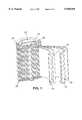
- the cell cyclabilityis preferably improved by including the Group 1 element on a surface of the separator between the separator and the positive electrode.
- FIG. 1is a sectional view of a storage cell
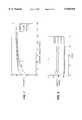
- FIG. 2is a graph depicting the voltage for various charge capacities for a lithium ion cell.
- FIG. 3is a graph depicting the discharge capacity of a lithium ion cell having a separator with a lithium deposit and a lithium ion cell without a lithium deposit.
- FIG. 4is a graph depicting the first cycle charge/discharge capacity of a lithium ion cell having a separator with a lithium deposit and a lithium ion cell without a lithium deposit.
- FIG. 5is a graph depicting the first cycle charge/discharge capacity of a lithium ion cell having a separator with a lithium deposit and a lithium ion cell without a lithium deposit.
- FIG. 6is a graph depicting the cyclability of a lithium ion cell having a separator with a lithium deposit and a lithium ion cell without a lithium deposit.
- FIG. 7is a graph depicting the first cycle charge/discharge capacity of a lithium ion cell having a separator with a lithium deposit and a lithium ion cell without a lithium deposit.
- FIG. 8is a graph depicting the cyclability of a lithium ion cells having a separator with different thicknesses of a lithium deposit and a lithium ion cell without a lithium deposit.
- FIG. 9is a graph depicting the cyclability of a lithium ion cells having a separator with different thicknesses of a lithium deposit and a lithium ion cell without a lithium deposit.
- the storage cellor battery, includes a negative electrode 10 in electrical contact with negative lead 12, a positive electrode 14 in electrical contact with positive lead 16, and a separator 18.
- the electrodes and the separatorare contained within case 20.
- One end of case 20is closed with cap 22 and annular insulating gasket 24 that provide a gas-tight and fluid-tight seal.
- Positive lead 16connects positive electrode 14 to cap 22.
- Cap 22includes a safety valve 26 disposed in the inner side of cap 22 which is configured to release pressure inside the cell when it exceeds a predetermined value.
- Positive electrode 14can include, for example, LiNiO 2 , LiCoO 2 , LiMn 2 O 4 cobalt- or aluminum-doped LiNiO 2 , or fluorine-doped LiMn 2 O 4 .
- Negative electrode 10can be, for example, a carbonaceous electrode including graphite, carbon, acetylene black, mesophase carbons, polyacenic semiconductors, or a metal oxide material such as amorphous doped tin oxide.
- the electrode materiale.g., carbon or metal oxide
- a polymeric binding mediume.g., polyethylene glycol
- Electrode pieces of the appropriate sizecan be cut from the substrate.
- Separator 18is a porous polymer film or thin sheet that serves as a spacer and is composed of relatively non-reactive polymers such as, for example, polypropylene, polyethylene, a polyamide (i.e., a nylon), a polysulfone, or polyvinyl chloride (PVC).
- the separatoris porous and prevents contact between the electrodes while allowing the electrolyte to move through the pores.
- the separatorhas a thickness between about 0.1 mm to 2.00 mm, preferably between about 0.20 mm to 0.50 mm.
- the separatorpreferably carries the composition including the Group 1 element. The separator does not react with the Group 1 element during the deposition process and can have a better tolerance for the deposition conditions than the electrode materials.
- a separator having lithium deposits that is used in a lithium ion cellcan provide low overall irreversibility, high charge capacity, and good cyclability.
- Separator 18is cut into pieces of a similar size as the electrodes, and is placed between the negative and positive electrodes to separate them electrically.
- the electrodes and separatorare wound into a Swiss roll, or jelly roll, as shown in FIG. 1, and placed in a case made of a metal such as nickel or nickel plated steel, or a plastic material such as PVC, polypropylene, a polysulfone, ABS, or a polyamide.
- the electrodes and separatorcan be cut to an appropriate size and sealed in a coin cell.
- Case 20containing the electrodes and separator, is filled with an electrolyte.
- the electrolytemay be any electrolyte known in the art.
- a preferred electrolyteis a 1M solution of LiPF 6 in an ethylene carbonate/dimethyl carbonate mixture.
- case 20is then sealed with cap 22 and annular insulating gasket 24.
- High capacity carbon electrodes and metal oxide anodes which have capacities in excess of 500 mAh/gcan be highly irreversible. Irreversible capacity loss during the first charge/discharge cycle in the negative electrode or positive electrode can be reduced by including a thin deposit of a composition including a Group 1 element between the positive and negative electrodes in the lithium ion cell.
- the deposithas an average thickness less than 30 microns, preferably less than 20 microns, and more preferably less than 10 microns.
- the depositcan form a continuous layer over a surface of the separator.
- the compositioncan be deposited on a surface of the positive electrode, a surface of the negative electrode, a surface of the separator, or combinations thereof.
- cyclability of the cellis improved in comparison to cells that do not include the deposit.
- irreversibility in the charge/discharge cyclesis reduced.
- the cell capacitycan be increased by at least 10 percent when compared to a similar cell that does not include the Group 1 element.
- the Group 1 elementcan be present in an amount capable of eliminating an irreversible capacity of the cell.
- the lithium ion cells prepared with the depositscan have improved 60° C. storability in comparison to lithium ion cells that were not prepared with the deposits.
- the depositcan include a Group 1 element (e.g., lithium metal) which can reduce or eliminate the amount of lithiated metal oxides used in the lithium ion cell.
- a Group 1 elemente.g., lithium metal
- the compositionincludes a Group 1 element.
- the Group 1 elementincludes lithium, sodium, or potassium.
- the Group 1 elementcan be metals or metallic alloys, such as, for example, lithium metal, sodium metal, potassium metal, lithium silicon alloy, or lithium aluminum alloy.
- the compositioncan be vacuum deposited to form the deposits in the cells. Lithium metal is preferred since it is less reactive than the other Group 1 metals and is part of typical lithium ion cells.
- Alternative group 1 elementscan be used in conjunction with suitable positive and negative electrodes.
- Thin deposits(typically a few microns in thickness) of the composition (e.g., lithium, sodium, potassium, or lithium compounds) can be deposited on the carbon electrode surface by sputtering, evaporation, electron beam etching, vacuum deposition, or vapor deposition techniques. Alternatively, the deposits can be applied to a surface of the other electrode (i.e., the metal oxide electrode surface) or a surface of the separator by the same techniques.
- the deposition methodsreduce the need to handle fragile, micron-thick metallic lithium foils that are not mechanically strong. The methods can be used to apply a thin deposit to any material suitable for use in a battery.
- the preferred composition for the depositis lithium metal.
- the overall reversible charge capacity in a cellcan be increased by 10% to 30% when a thin layer of lithium metal is included in the cell.
- the thin layer of lithium metalis less than 30 microns thick, preferably less than 20 microns thick, and most,preferably less than 10 microns thick (e.g., between 3 and 8 microns thick). The thin layer can help uniformly distribute the lithium metal throughout the cell.
- Cell designcan be aided by determining the appropriate amount of lithium metal to be deposited (i.e., on the separator).
- the amountcan be calculated using the following equation (2):
- Q irre negis the total irreversible capacity of the negative electrode material (in mAh/g)
- Q Li gis the gravimetric capacity of one gram of lithium metal (3860 mAh/g).
- the appropriate average thickness of the lithium layer to be depositedcan be calculated following equation (3):
- Q irre negis the total irreversible capacity of the negative electrode material (in mAh/cm 2 )
- Q Li Vis the volumetric capacity of one cubic centimeter of lithium metal (7283 mAh/cm 3 ).
- the cellBy compensating for the irreversibility of the electrode with added lithium in the deposit, the cell is designed to maximize the benefit of this added lithium.
- the total irreversible capacitycan be determined by taking the difference between the charge capacity and the discharge capacity.
- the charge and discharge capacities of a reversible electrochemical cellare determined by charging or discharging a cell with conventional electrical power supplies and integrating the current over time to calculate the total charge delivered by the cell.
- Equations (2) and (3)can be modified for other compositions by using the gravimetric capacity of the material.
- the volumetric capacitycan be determined by multiplying the gravimetric capacity by the density of the material.
- the lithium depositPrior to or after two or three charge/discharge cycles, the lithium deposit is consumed, resulting in the formation of a lithium ion cell which consists of lithiated metal oxide cathode and carbon anode.
- the deposit materialis incorporated into active cyclable lithium.
- the operation of a lithium ion cell including a separator having a lithium metal deposit in this mannercan be unexpected since the lithium metal deposit reduces the porosity of the separator.
- the separator having a depositmay act as a bipolar electrode.
- the currentcauses residual lithium metal to strip from one side quantitatively as lithium is deposited on the other.
- the lithium being depositedmakes electrical contact with the neighboring electrode and there is a direct reaction with the partially charged/discharged electrode.
- the lithium metal carried into the cell via the separatoris incorporated as active cyclable lithium, thereby increasing the capacity of the rechargeable cell.
- the crucible containing lithiumwas loaded into a tungsten basket heater (EVB8A3030W, Kurt J. Lesker Company).
- the distance between the lithium metal source and the separatorranged between 25 to 10 centimeters, depending on the desired lithium deposit thickness.
- Celgard 2300 separator specimens(6 ⁇ 9 centimeters) were mounted on the rotating plate located above the lithium source (25 centimeters). After reducing the pressure in the chamber to about 10 -6 torr, a 15 mA current was passed through the basket heater for 2-3 minutes to preheat the lithium metal and crucible. The heater turned to red color for a few minutes. The current was gradually increased to 19-20 mA. After 3-5 minutes at the higher current level, the lithium metal was heated to a temperature close to its boiling point at the pressure in the chamber and the lithium started to evaporate. This was confirmed by a darkening of the transparent bell jar. The operation was continued for an additional 5 minutes. The current was gradually reduced to zero.
- the plate above the lithium sourcewas continually rotated at a constant speed between 5 and 50 rotations per minute. After 30 minutes cooling down, the chamber was vented with high purity argon gas. A shiny, silver-like deposit can be seen on the surface of the coated separator specimens.
- the average thickness of the lithium deposit deposited on the separatorwas calculated from the total amount of lithium in the solution, total area of the disk, and the physical density of lithium.
- the average thickness of the lithium deposits in Trial #1were 0.5-1.5 ⁇ m.
- Celgard 2300 separator specimens(6 ⁇ 20 centimeters) were mounted on the plate above the lithium source. The distance between lithium source and separator specimens was reduced to 15 centimeters. The deposition experiment then was carried out following the procedures described in Trial #1.
- the lithium deposits on the separator specimenswere analyzed following the same procedures used in Trial #1.
- the average thickness of the lithium deposits in Trial #2were 2.0-2.5 ⁇ m.
- a carbon electrode containing mesocarbon microbeads (MCMB)(hereafter, referred as "MCMB"), conductive material, Shawinigan acetylene black (SAB), and polyvinylidenefluoride (PVDF) binder in a ratio of about 85:5:10 by weight (MCMB:SAB:PVDF) was prepared by the following procedure.
- MCMBmesocarbon microbeads
- SABShawinigan acetylene black
- PVDFpolyvinylidenefluoride
- a solution of PVDFwas made by dissolving PVDF in N-methyl pyrrolidone (NMP) with stirring overnight.
- NMPN-methyl pyrrolidone
- MCMB powder and SABwere mixed in a rotary mixture for 20 minutes based on the ratio described above.
- the powder mixturewas added to the binder solution gradually with stirring to form a wet slurries.
- the wet slurrywas coated on a copper foil substrate (about 200 ⁇ m in thickness) which acts as a current collector.
- the electrodeswere dried at a temperature up to about 200° C. for 10 hours to remove the residual solvent. After cooling to room temperature, the electrodes were calendered with a pressure of between 500 and 2000 psi in a roller.
- the carbon electrodeswere dried at 150° C. for at least 4 hours before depositing a lithium coating on the surface.
- the electrodeswere mounted on the rotating plate in the evaporator which was located 25 centimeters above the lithium source.
- the lithium depositwas made using the procedure described in Example 1.
- a copper foil substratewas placed along side the carbon electrode as a control to confirm deposition of lithium.
- the lithium deposit deposited on the copper foil and carbon electrodewas stable in the dry room atmosphere for at least 3 days. In contrast, chemically prepared pre-lithiated electrodes were very unstable in a dry-room atmosphere and decomposed rapidly.
- the thickness of the lithium deposit deposited on copper foilwas between 1 and 2 microns, as determined by the method described in Example 1.
- Coin type cells with a lithium metal electrode and a carbon electrode having the lithium depositwas made by laminating 1.43 centimeter diameter disks of lithium metal and carbon electrodes.
- a Celgard 2300 separator (1.91 centimeters in diameter)was placed in between the lithium metal electrode and the carbon electrode, with the lithiumcoated surface of the carbon electrode facing the separator.
- the cellswere filled with LiPF 6 in EC/DMC (a non-aqueous electrolyte).
- the cellswere sealed using a crimper so that the electrolyte would not leak out of the cell.
- the assembly of the coin cellswas carried out in a glove box which was filled with inert gas to protect against decomposition or other adverse reactions caused by moisture.
- coin cells with a carbon electrode that did not have the lithium depositwere made as a control.
- the coin cellswere discharged with a constant current of 0.2 mA (0.12 mA/cm 2 ) to 0.001 V versus lithium metal.
- the discharge curves of cells made from the carbon electrode having the lithium deposit and the control cellare shown in FIG. 2.
- the cell having the lithium coated carbon electrodeshowed no first cycle irreversible capacity loss. Irreversible capacity loss can be suggested by a passivation plateau, such as the one that was present in the discharge curve of control cell.
- the reversible charge capacity of the cellwas increased by about 10% to 20% over a comparable cell without the lithium deposit.
- Lithium ion coin cellswere assembled from an anode (MCMB electrode), cathode (LiCoO 2 ), and a Celgard 2300 separator.
- the separatoroptionally had a lithium deposit, prepared as described in Example 1.
- the lithiumwas deposited to an average thickness of about 3.6 ⁇ m, as determined by the method described in Example 1.
- the MCMB electrodewas prepared by the procedures described in Example 2.
- the LiCoO 2 electrodewas prepared by compressing LiCoO 2 powder (92%), SAB conductive material (3%), and a polytetrafluoroethylene (PTFE) binder (5%) on an aluminum grid substrate in a die having a diameter of 1.43 centimeters.
- PTFEpolytetrafluoroethylene
- Disk-like electrodes and separatorthat were 1.59 centimeters in diameter were used to assemble the coin cells.
- the cellswere balanced by using the capacity of the active materials at the first lithiation/delithiation (change) of 330 mAh/g for the MCMB electrode and 140 mAh/g for the LiCoO 2 electrode.
- the anode and cathodewere dried at about 150° C. for 16 and 4 hours, respectively.
- the coin cellswere assembled by facing the surface of separator having the lithium deposit toward to the cathode (face-the-cathode; FTC) or the anode (face-the-anode; FTA), respectively. Control cells were assembled using an unmodified separator. Cell assembly was completed in a glove box filled with argon gas. LiPF 6 in EC/DMC was used as the non-aqueous electrolyte.
- the lithium ion coin cellswere cycled between 2.8 and 4.2 V with a current of 0.5 mA (0.31 mA/cm 2 based on cathode surface area). The cells were evaluated under two cycling conditions, as described in Trials #3 and #4, respectively.
- Coin cells with the separator having a lithium deposit and FTC configurationwere charged to 4.2 V at a constant current of 0.5 mA (0.31 mA/cm 2 ) following trickling at the voltage. The charge was stopped after 24 hours in this trial. After one hour of rest from the end of charge, the cells were discharged to 2.8 V with a constant current of 0.5 mA (0.31 mA/cm 2 ). The next charge/discharge cycle started after one hour of rest from the previous discharge. The charge/discharge cycling test was continued for up to thirty cycles. For comparison, control cells were cycled under the same conditions.
- FIG. 3shows the discharge capacity of FTC cells and the control cells. There were two cells in each group (e.g., FTC and control). The cell capacities were presented in gravimetric capacities based on active anode and cathode materials. The top set of curves represent the anode gravimetric capacity, while the bottom set of curves represent cathode gravimetric capacity. The FTC cells had higher discharge capacities than the control cells. At cycle 5, for example, the anode discharge capacity of cells with lithium deposit was 311 mAh/g (two cells average). In contrast, the discharge capacity of cells without lithium deposit was 248 mAh/g.
- FTC cellsi.e., with separator having the lithium deposit
- control cellsi.e., without the lithium deposit
- the anode discharge capacitycan be improved by about 25-30% by using separator having lithium deposit.
- FTA and FTC coin cellswere cycled by a constant current and low voltage cut-off regime.
- the cellswere charged to 4.1 V at 0.5 mA (0.31 mA/cm 2 based on cathode surface area) without trickle and were discharged to 2.8 V at the same current density.
- the rest time after both charge and dischargewas about one hour.
- the cycling testwere continued for up to thirty cycles. For comparison, control cells were tested under the same conditions.
- FIGS. 4 and 5show the change in cell charge/discharge capacity at first cycle as the cell voltage is changed.
- cells having the separator with the lithium deposit in the FTA configurationwere compared to the control cells.
- the FTA cellshad a lower irreversible capacity than the control cells.
- the irreversible capacity in the FTA cells and the control cellswere 18 and 30 mAh/g, respectively, which was about 40% lower than control cell.
- cells having the separator with the lithium deposit in the FTC configurationwere compared to the control cells.
- the FTC cellshad a higher charge capacity than the control cells.
- the first charge capacitywas 125 mAh/g cathode for the FTC cell and 105 mAh/g cathode for the control cell.
- the irreversible capacity after first discharge in the FTC cell(40 mAh/g), however, was larger than in the control cell (30 mAh/g).
- FIG. 6is a plot of the anode gravimetric discharge capacity as a function of the cycle number applied for cells in three different configurations.
- Cells having the lithium deposit on the separator in the FTC or FTA configurationhad higher discharge capacities than the control cells.
- the FTC configurationdelivered the highest discharge capacity at cycle five (258 mAh/g).
- the control cellhad a discharge capacity at cycle five of 203 mAh/g.
- the discharge capacity of this trialwas lower than that obtained in Trial #3 at the same cycle number (i.e., 258 mAh/g compared to 311 mAh/g at cycle five). This can be due to the low cut-off voltage and the lack of trickle charge regime in this trial (i.e., 4.1 V rather than 4.2 V with trickle).
- Lithium and cobalt contents of the cathode materialswere determined by chemical analysis.
- the cathode materials from the examined cellswere heated in a HCl/H 2 O 2 solution to boiling for at least 4 hours.
- the solutionwas filtered and diluted to a known volume.
- the solutionwas analyzed by ICP against matrix-matched standards to determine the lithium and cobalt contents of the electrodes.
- Table Ishows the analytical results for the FTC cells and control cells.
- the cathode materials taken from the FTC cellshad higher lithium concentrations than the control cells, as indicated by the larger molar ratio. The higher lithium concentrations suggest that the lithium deposit facing the cathode can deliver excess charge capacity during cycling.
- Lithium metalwas deposited on Celgard 2300 separator as described in Example 3.
- the depositshad average thicknesses of 4 and 8 ⁇ m, respectively, as determined by the method described in Example 1.
- the lithium ion coin cellswere made from an MCMB anode, a spinel LiMn 2 O 4 cathode, and the Celgard 2300 separator. A separator without the lithium deposits was used to prepare control cells.
- the anodes and cathodeswere made by the procedures described in Examples 2 and 3.
- the separators(1.59 centimeter in diameter) having the two thickness of lithium deposits were used in cell assembly.
- the cellswere designed to be balanced by a 10% excess anode capacity based on the capacities of active materials (e.g., 330 mAh/g for the MCMB electrode and 120 mAh/g for the LiMn 2 O 4 electrode) during the first lithiation/delithiation cycle.
- active materialse.g., 330 mAh/g for the MCMB electrode and 120 mAh/g for the LiMn 2 O 4 electrode
- FTC, FTA and control coin cellswere assembled.
- the non-aqueous electrolytewas LiPF 6 in EC/DMC.
- FIG. 7shows a plot of the charge/discharge capacity against the voltage at the first cycle for the FTC cells having lithium deposits 4 and 8 ⁇ m thick, respectively, and the control cell.
- a voltage plateauwas found during the first charge around 3 V, which is considered an indicator of lithium intercalation into the spinel structure.
- the capacity regimes in which a voltage plateau presentsappear to be nearly proportional to the average thickness of the lithium deposit.
- the charge capacityalso increases with the average thickness of lithium deposit.
- FIGS. 8 and 9depict the cyclability of FTA, FTC, and control cells.
- the FTC and FTA cellsdelivered higher discharge capacity than the control cell over thirty cycles.
- the FTC and FTA cellshad nearly the same cyclability over the thirty cycles.
Landscapes
- Chemical & Material Sciences (AREA)
- Chemical Kinetics & Catalysis (AREA)
- Electrochemistry (AREA)
- General Chemical & Material Sciences (AREA)
- Engineering & Computer Science (AREA)
- Manufacturing & Machinery (AREA)
- Materials Engineering (AREA)
- Secondary Cells (AREA)
- Battery Electrode And Active Subsutance (AREA)
- Cell Separators (AREA)
Abstract
Description
This invention relates to rechargeable lithium ion electrochemical cells.
A battery includes one or more galvanic cells (i.e., cells that produce a direct current of electricity) in a finished package. In each cell, two electrodes are separated by an electron insulator, but are joined by an ion-carrying path. The electron-carrying path of the battery is external; the path proceeds, via a conductor, through a device where work is done. The ion-carrying path of the battery is internal and proceeds via an electrolyte.
The electrodes are usually composed of dissimilar metals. The electrode where an electrolytic species receives electrons is the positive electrode, also referred to as the cathode. The electrode where an electrolytic species goes into solution, releasing electrons, is called the negative electrode, or anode. The electrolyte generally is composed mainly of an ionizable salt dissolved in a solvent.
Batteries may be rechargeable; such batteries are called "storage" or "secondary" batteries. Storage batteries can be recharged by passing current through the cells in the opposite direction of discharge current flow. The charging current restores the chemical conditions of the battery, preparing it to be discharged again. Primary batteries, on the other hand, are meant to be discharged to exhaustion once, and then discarded.
An example of a rechargeable battery is a lithium ion cell. The positive electrode of this cell can include, for example, a lithiated metal oxide, such as LiCoO2, LiNiO2, or LiMn2 O4. The negative electrode can be, for example, a carbon or metal oxide electrode. The electrolyte in lithium ion cells can include a lithium salt (e.g., LiPF6 or LiClO4) dissolved in an aprotic solvent such as, for example, propylene carbonate or ethylene carbonate. An electrode separator is located between the positive electrode and negative electrode to prevent physical and electrical contact between the electrodes. Physical contact between the positive electrode and negative electrode leads to short circuiting which discharges the cell. The electrode separator insulates the electrodes from contact. The separator is porous (e.g., a porous organic polymer) and allows the electrolyte to migrate from one electrode to the other.
An example of the electrochemical process in a lithium-ion battery is as follows: ##STR1## where A2 Bw represents the negative electrode (e.g., carbon), Liy Mn Ym represents the positive electrode (e.g., LiCoO2), Li(y-x)Mn Ym represents the lithium-depleted positive electrode (e.g., LiCoO2 /CoO2), and Lix Az Bw represents the lithium-enriched negative electrode (e.g., Lix C6). The lithiated metal oxide provides the source of lithium ions which shuffle back and forth between anode and cathode when the cell is charged and discharged.
Generally, the charge (or discharge) capacity is the amount of charge the cell accepts (or provides) to reach to the charge (or discharge) voltage (e.g., of 4.1 V or 2.8 V). The difference between charge and discharge capacity is the irreversible charging capacity.
Lithium ion cells tend to exhibit a loss in charging capacity during the first few charge/discharge cycles, which is possibly due to consumption of lithium. The loss in charging capacity is irreversible, and leads to decreased charge capacities in the cells because the positive electrode is not fully lithiated.
A characteristic of the materials used for both positive and negative electrodes is their intrinsic partial irreversibility. When carbon is used as a negative electrode in a lithium ion cell, the first charging capacity is always significantly higher than the first discharge capacity. For common carbon negative electrode materials, the irreversibility ranges from 10% to 30% of the first charge capacity (i.e., the first discharge capacity is only 90% to 70% of the first charge capacity). For typical positive electrode materials, however, the irreversibility is generally much lower. For LiCoO2, for example, the first charge/discharge irreversibility is less than 5%. That is, the first discharge capacity is 95% of the first charge capacity.
Consequently, for design efficiency, the electrodes in a rechargeable cell generally are balanced (i.e., each electrode should have the same capacity). When positive and negative electrodes of different irreversibility are used together in a rechargeable cell, the cell typically is balanced in a manner that the first charge capacities of the two electrodes are the same. On use, the cell will only cycle to the reversible capacity of the most irreversible electrode. Therefore, the full reversible portion of the other electrode is not fully utilized. This can result in a lower than maximum capacity of the completed electrochemical cell.
The invention generally relates to placing aGroup 1 element (e.g., lithium metal) between a positive electrode and negative electrode in a lithium ion cell in order to efficiently balance the electrodes of the cell. TheGroup 1 element, for example, may be a thin deposit on the surface of a separator, or on the surface of either electrode. The invention provides a number of potential benefits.
For example, theGroup 1 element can be used to reduce or even eliminate an irreversible charging capacity in the cell by compensating for the irreversible capacity of one or both electrodes. The irreversible charging capacity can be reduced or eliminated by permitting the positive electrode (when using lithium or lithium ions in the cell) to be fully lithiated prior to or during the first few charge/discharge cycles. An electrode is lithiated by incorporating lithium or lithium ions into a host lattice, such as a carbon or metal oxide lattice. The lithium can be transported into and out of the host lattice. The electrode is fully lithiated when the host lattice cannot accept more lithium. TheGroup 1 element (e.g., lithium metal) can provide some or all of the additional charged material consumed during the first few charge/discharge cycles; as a result, fewer lithium or lithium ions in the host lattice are consumed.
Moreover, theGroup 1 element can be used to increase the capacity of the cell. The overall reversible charge-carrying capacity of the cell increases when theGroup 1 element is initially carried or located between the electrodes by allowing the positive electrode to be more completely lithiated during charging and thus allowing the balance to be optimized for maximum capacity.
Furthermore, theGroup 1 element can be used to increase the charging reversibility of the cell. The charge is reversible when the amount of charge that an electrode can carry does not change by more than 10 percent, preferably less than or equal to 5 percent. By placing an amount of aGroup 1 element capable of reducing an irreversible capacity of the cell between a positive electrode and a negative electrode of the cell before the first charging cycle of the cell, preferably between the separator and the negative electrode, the charging reversibility of the cell is increased.
In addition, theGroup 1 element can be used to improve rechargeable cell cyclability. The charging capacity of a cell decreases as the cell is charged and discharged. By placing aGroup 1 element between a positive electrode and a negative electrode of the cell before the first charging cycle of the cell, the charge capacity of the cell decreases by less than 20 percent, more preferably less than 10 percent, over 30 charging cycles. The cell cyclability is preferably improved by including theGroup 1 element on a surface of the separator between the separator and the positive electrode.
Other features and advantages of the invention will be apparent from the description of the preferred embodiments and from the claims.
FIG. 1 is a sectional view of a storage cell; and
FIG. 2 is a graph depicting the voltage for various charge capacities for a lithium ion cell.
FIG. 3 is a graph depicting the discharge capacity of a lithium ion cell having a separator with a lithium deposit and a lithium ion cell without a lithium deposit.
FIG. 4 is a graph depicting the first cycle charge/discharge capacity of a lithium ion cell having a separator with a lithium deposit and a lithium ion cell without a lithium deposit.
FIG. 5 is a graph depicting the first cycle charge/discharge capacity of a lithium ion cell having a separator with a lithium deposit and a lithium ion cell without a lithium deposit.
FIG. 6 is a graph depicting the cyclability of a lithium ion cell having a separator with a lithium deposit and a lithium ion cell without a lithium deposit.
FIG. 7 is a graph depicting the first cycle charge/discharge capacity of a lithium ion cell having a separator with a lithium deposit and a lithium ion cell without a lithium deposit.
FIG. 8 is a graph depicting the cyclability of a lithium ion cells having a separator with different thicknesses of a lithium deposit and a lithium ion cell without a lithium deposit.
FIG. 9 is a graph depicting the cyclability of a lithium ion cells having a separator with different thicknesses of a lithium deposit and a lithium ion cell without a lithium deposit.
Referring to FIG. 1, the storage cell, or battery, includes anegative electrode 10 in electrical contact withnegative lead 12, apositive electrode 14 in electrical contact withpositive lead 16, and aseparator 18. The electrodes and the separator are contained withincase 20. One end ofcase 20 is closed withcap 22 and annular insulatinggasket 24 that provide a gas-tight and fluid-tight seal.Positive lead 16 connectspositive electrode 14 to cap 22.Cap 22 includes asafety valve 26 disposed in the inner side ofcap 22 which is configured to release pressure inside the cell when it exceeds a predetermined value.
The electrode material (e.g., carbon or metal oxide) is mixed with a polymeric binding medium to produce a paste which is applied to a highly porous sintered, felt, or foam substrate. Electrode pieces of the appropriate size can be cut from the substrate.
Once filled with electrolyte,case 20 is then sealed withcap 22 and annular insulatinggasket 24.
High capacity carbon electrodes and metal oxide anodes which have capacities in excess of 500 mAh/g can be highly irreversible. Irreversible capacity loss during the first charge/discharge cycle in the negative electrode or positive electrode can be reduced by including a thin deposit of a composition including aGroup 1 element between the positive and negative electrodes in the lithium ion cell. The deposit has an average thickness less than 30 microns, preferably less than 20 microns, and more preferably less than 10 microns.
The deposit can form a continuous layer over a surface of the separator. The composition can be deposited on a surface of the positive electrode, a surface of the negative electrode, a surface of the separator, or combinations thereof. When the composition is located between the separator and the positive electrode, cyclability of the cell is improved in comparison to cells that do not include the deposit. When the composition is located between the separator and the negative electrode, irreversibility in the charge/discharge cycles is reduced. The cell capacity can be increased by at least 10 percent when compared to a similar cell that does not include theGroup 1 element. TheGroup 1 element can be present in an amount capable of eliminating an irreversible capacity of the cell. The lithium ion cells prepared with the deposits can have improved 60° C. storability in comparison to lithium ion cells that were not prepared with the deposits.
Chemical or electrochemical pre-lithiation of the positive electrode, which can form lithiated materials that are unstable in air, can be avoided. Accordingly, since the cells can be prepared without pre-lithiated metal oxide materials, other high capacity metal oxides (e.g., derivatives of manganese oxides, vanadium oxides, or iron oxides) or insertion compounds can be used as positive electrode materials. The deposit can include aGroup 1 element (e.g., lithium metal) which can reduce or eliminate the amount of lithiated metal oxides used in the lithium ion cell.
The composition includes aGroup 1 element. TheGroup 1 element includes lithium, sodium, or potassium. TheGroup 1 element can be metals or metallic alloys, such as, for example, lithium metal, sodium metal, potassium metal, lithium silicon alloy, or lithium aluminum alloy. The composition can be vacuum deposited to form the deposits in the cells. Lithium metal is preferred since it is less reactive than theother Group 1 metals and is part of typical lithium ion cells.Alternative group 1 elements can be used in conjunction with suitable positive and negative electrodes.
Thin deposits (typically a few microns in thickness) of the composition (e.g., lithium, sodium, potassium, or lithium compounds) can be deposited on the carbon electrode surface by sputtering, evaporation, electron beam etching, vacuum deposition, or vapor deposition techniques. Alternatively, the deposits can be applied to a surface of the other electrode (i.e., the metal oxide electrode surface) or a surface of the separator by the same techniques. The deposition methods reduce the need to handle fragile, micron-thick metallic lithium foils that are not mechanically strong. The methods can be used to apply a thin deposit to any material suitable for use in a battery.
The preferred composition for the deposit is lithium metal. The overall reversible charge capacity in a cell can be increased by 10% to 30% when a thin layer of lithium metal is included in the cell. The thin layer of lithium metal is less than 30 microns thick, preferably less than 20 microns thick, and most,preferably less than 10 microns thick (e.g., between 3 and 8 microns thick). The thin layer can help uniformly distribute the lithium metal throughout the cell.
Cell design can be aided by determining the appropriate amount of lithium metal to be deposited (i.e., on the separator). The amount can be calculated using the following equation (2):
M.sub.Li (gram)=(Q.sub.irre neg)/Q.sub.Li g (2)
where Qirre neg is the total irreversible capacity of the negative electrode material (in mAh/g), QLi g is the gravimetric capacity of one gram of lithium metal (3860 mAh/g).
Alternatively, the appropriate average thickness of the lithium layer to be deposited (i.e., on the separator) can be calculated following equation (3):
T.sub.Li (micron)=(Q.sub.irre neg)/Q.sub.Li V ×10.sup.-4(3)
where Qirre neg is the total irreversible capacity of the negative electrode material (in mAh/cm2), QLi V is the volumetric capacity of one cubic centimeter of lithium metal (7283 mAh/cm3).
By compensating for the irreversibility of the electrode with added lithium in the deposit, the cell is designed to maximize the benefit of this added lithium.
The total irreversible capacity can be determined by taking the difference between the charge capacity and the discharge capacity. The charge and discharge capacities of a reversible electrochemical cell are determined by charging or discharging a cell with conventional electrical power supplies and integrating the current over time to calculate the total charge delivered by the cell.
Equations (2) and (3) can be modified for other compositions by using the gravimetric capacity of the material. The gravimetric capacities of the alkali metals and some lithium compounds are: lithium=3861 mAh/g; sodium=1166 mAh/g; potassium=686 mAh/g; lithium fluoride =1033 mAh/g; lithium chloride=632 mAh/g; lithium bromide =309 mAh/g; and lithium iodide=200 mAh/g. The volumetric capacity can be determined by multiplying the gravimetric capacity by the density of the material.
Prior to or after two or three charge/discharge cycles, the lithium deposit is consumed, resulting in the formation of a lithium ion cell which consists of lithiated metal oxide cathode and carbon anode. The deposit material is incorporated into active cyclable lithium. The operation of a lithium ion cell including a separator having a lithium metal deposit in this manner can be unexpected since the lithium metal deposit reduces the porosity of the separator.
Prior to the initial charging of the cell, some of the lithium deposit can electrochemically react with the electrode against which is positioned. Even if the lithium deposit is not completely reacted, there is a means by which the deposit may react.
Without intending to be bound to any one theory, it appears that when current is passed through the cell in a lithium electrolyte, the separator having a deposit may act as a bipolar electrode. The current causes residual lithium metal to strip from one side quantitatively as lithium is deposited on the other. Eventually, the lithium being deposited makes electrical contact with the neighboring electrode and there is a direct reaction with the partially charged/discharged electrode. Ultimately, the lithium metal carried into the cell via the separator is incorporated as active cyclable lithium, thereby increasing the capacity of the rechargeable cell.
The following examples illustrate the invention.
Coating experiments were performed in a Denton Vacuum DV-502 model High Vacuum Evaporator machine located in a dry room where the relative humidity is below 1.5 percent. The deposits were prepared in a chamber which was under a high vacuum of 10-6 torr and covered by a transparent bell jar which allowed the operator to watch the inside of the chamber during operation. The polymeric separator, (e.g., Celgard 2300 separator) was placed on a rotating plate which is mounted in the upper part of vacuum chamber above a lithium source. Lithium metal (0.05 gram) (99+% Purity) was loaded in an aluminum oxide crucible (1.8 cm outer diameter (OD)×1.8 cm height, Kurt J. Lesker Company). The crucible containing lithium was loaded into a tungsten basket heater (EVB8A3030W, Kurt J. Lesker Company). The distance between the lithium metal source and the separator ranged between 25 to 10 centimeters, depending on the desired lithium deposit thickness.
Celgard 2300 separator specimens (6×9 centimeters) were mounted on the rotating plate located above the lithium source (25 centimeters). After reducing the pressure in the chamber to about 10-6 torr, a 15 mA current was passed through the basket heater for 2-3 minutes to preheat the lithium metal and crucible. The heater turned to red color for a few minutes. The current was gradually increased to 19-20 mA. After 3-5 minutes at the higher current level, the lithium metal was heated to a temperature close to its boiling point at the pressure in the chamber and the lithium started to evaporate. This was confirmed by a darkening of the transparent bell jar. The operation was continued for an additional 5 minutes. The current was gradually reduced to zero. During the operation, the plate above the lithium source was continually rotated at a constant speed between 5 and 50 rotations per minute. After 30 minutes cooling down, the chamber was vented with high purity argon gas. A shiny, silver-like deposit can be seen on the surface of the coated separator specimens.
Three discs (each 1.59 centimeters in diameter) were punched out from the separator deposited with lithium and placed in a 7 mL vial which was sealed in the dry room. Outside the dry room, five milliliters of water was introduced into each vial using a 10 mL syringe. The lithium deposited on separator reacted with water immediately and was converted to lithium hydroxide. The resulting solution was analyzed by inductively coupled plasma atomic emission spectroscopy (ICP) and the total concentration of lithium was determined against a standard acid solution.
The average thickness of the lithium deposit deposited on the separator was calculated from the total amount of lithium in the solution, total area of the disk, and the physical density of lithium. The average thickness of the lithium deposits inTrial # 1 were 0.5-1.5 μm.
Celgard 2300 separator specimens (6×20 centimeters) were mounted on the plate above the lithium source. The distance between lithium source and separator specimens was reduced to 15 centimeters. The deposition experiment then was carried out following the procedures described inTrial # 1.
The lithium deposits on the separator specimens were analyzed following the same procedures used inTrial # 1. The average thickness of the lithium deposits inTrial # 2 were 2.0-2.5 μm.
A carbon electrode containing mesocarbon microbeads (MCMB) (hereafter, referred as "MCMB"), conductive material, Shawinigan acetylene black (SAB), and polyvinylidenefluoride (PVDF) binder in a ratio of about 85:5:10 by weight (MCMB:SAB:PVDF) was prepared by the following procedure.
A solution of PVDF was made by dissolving PVDF in N-methyl pyrrolidone (NMP) with stirring overnight. MCMB powder and SAB were mixed in a rotary mixture for 20 minutes based on the ratio described above. The powder mixture was added to the binder solution gradually with stirring to form a wet slurries. The wet slurry was coated on a copper foil substrate (about 200 μm in thickness) which acts as a current collector. The electrodes were dried at a temperature up to about 200° C. for 10 hours to remove the residual solvent. After cooling to room temperature, the electrodes were calendered with a pressure of between 500 and 2000 psi in a roller.
The carbon electrodes were dried at 150° C. for at least 4 hours before depositing a lithium coating on the surface. The electrodes were mounted on the rotating plate in the evaporator which was located 25 centimeters above the lithium source. The lithium deposit was made using the procedure described in Example 1. A copper foil substrate was placed along side the carbon electrode as a control to confirm deposition of lithium.
The lithium deposit deposited on the copper foil and carbon electrode was stable in the dry room atmosphere for at least 3 days. In contrast, chemically prepared pre-lithiated electrodes were very unstable in a dry-room atmosphere and decomposed rapidly. The thickness of the lithium deposit deposited on copper foil was between 1 and 2 microns, as determined by the method described in Example 1.
Coin type cells with a lithium metal electrode and a carbon electrode having the lithium deposit was made by laminating 1.43 centimeter diameter disks of lithium metal and carbon electrodes. A Celgard 2300 separator (1.91 centimeters in diameter) was placed in between the lithium metal electrode and the carbon electrode, with the lithiumcoated surface of the carbon electrode facing the separator. The cells were filled with LiPF6 in EC/DMC (a non-aqueous electrolyte). The cells were sealed using a crimper so that the electrolyte would not leak out of the cell. The assembly of the coin cells was carried out in a glove box which was filled with inert gas to protect against decomposition or other adverse reactions caused by moisture. For comparison, coin cells with a carbon electrode that did not have the lithium deposit were made as a control.
The coin cells were discharged with a constant current of 0.2 mA (0.12 mA/cm2) to 0.001 V versus lithium metal. The discharge curves of cells made from the carbon electrode having the lithium deposit and the control cell are shown in FIG. 2. The cell having the lithium coated carbon electrode showed no first cycle irreversible capacity loss. Irreversible capacity loss can be suggested by a passivation plateau, such as the one that was present in the discharge curve of control cell. The reversible charge capacity of the cell was increased by about 10% to 20% over a comparable cell without the lithium deposit.
Lithium ion coin cells were assembled from an anode (MCMB electrode), cathode (LiCoO2), and a Celgard 2300 separator. The separator optionally had a lithium deposit, prepared as described in Example 1. The lithium was deposited to an average thickness of about 3.6 μm, as determined by the method described in Example 1.
The MCMB electrode was prepared by the procedures described in Example 2. The LiCoO2 electrode was prepared by compressing LiCoO2 powder (92%), SAB conductive material (3%), and a polytetrafluoroethylene (PTFE) binder (5%) on an aluminum grid substrate in a die having a diameter of 1.43 centimeters.
Disk-like electrodes and separator that were 1.59 centimeters in diameter were used to assemble the coin cells. The cells were balanced by using the capacity of the active materials at the first lithiation/delithiation (change) of 330 mAh/g for the MCMB electrode and 140 mAh/g for the LiCoO2 electrode. The anode and cathode were dried at about 150° C. for 16 and 4 hours, respectively. The coin cells were assembled by facing the surface of separator having the lithium deposit toward to the cathode (face-the-cathode; FTC) or the anode (face-the-anode; FTA), respectively. Control cells were assembled using an unmodified separator. Cell assembly was completed in a glove box filled with argon gas. LiPF6 in EC/DMC was used as the non-aqueous electrolyte.
The lithium ion coin cells were cycled between 2.8 and 4.2 V with a current of 0.5 mA (0.31 mA/cm2 based on cathode surface area). The cells were evaluated under two cycling conditions, as described inTrials # 3 and #4, respectively.
Coin cells with the separator having a lithium deposit and FTC configuration were charged to 4.2 V at a constant current of 0.5 mA (0.31 mA/cm2) following trickling at the voltage. The charge was stopped after 24 hours in this trial. After one hour of rest from the end of charge, the cells were discharged to 2.8 V with a constant current of 0.5 mA (0.31 mA/cm2). The next charge/discharge cycle started after one hour of rest from the previous discharge. The charge/discharge cycling test was continued for up to thirty cycles. For comparison, control cells were cycled under the same conditions.
FIG. 3 shows the discharge capacity of FTC cells and the control cells. There were two cells in each group (e.g., FTC and control). The cell capacities were presented in gravimetric capacities based on active anode and cathode materials. The top set of curves represent the anode gravimetric capacity, while the bottom set of curves represent cathode gravimetric capacity. The FTC cells had higher discharge capacities than the control cells. Atcycle 5, for example, the anode discharge capacity of cells with lithium deposit was 311 mAh/g (two cells average). In contrast, the discharge capacity of cells without lithium deposit was 248 mAh/g.
After 30 cycles, FTC cells (i.e., with separator having the lithium deposit) delivered a 273 mAh/g anode discharge capacity, while control cells (i.e., without the lithium deposit) showed a 200 mAh/g anode discharge capacity. Thus, the anode discharge capacity can be improved by about 25-30% by using separator having lithium deposit.
FTA and FTC coin cells were cycled by a constant current and low voltage cut-off regime. The cells were charged to 4.1 V at 0.5 mA (0.31 mA/cm2 based on cathode surface area) without trickle and were discharged to 2.8 V at the same current density. The rest time after both charge and discharge was about one hour. The cycling test were continued for up to thirty cycles. For comparison, control cells were tested under the same conditions.
FIGS. 4 and 5 show the change in cell charge/discharge capacity at first cycle as the cell voltage is changed. Referring to FIG. 4, cells having the separator with the lithium deposit in the FTA configuration were compared to the control cells. The FTA cells had a lower irreversible capacity than the control cells. For instance, the irreversible capacity in the FTA cells and the control cells were 18 and 30 mAh/g, respectively, which was about 40% lower than control cell. Referring to FIG. 5, cells having the separator with the lithium deposit in the FTC configuration were compared to the control cells. The FTC cells had a higher charge capacity than the control cells. The first charge capacity was 125 mAh/g cathode for the FTC cell and 105 mAh/g cathode for the control cell. The irreversible capacity after first discharge in the FTC cell (40 mAh/g), however, was larger than in the control cell (30 mAh/g).
FIG. 6 is a plot of the anode gravimetric discharge capacity as a function of the cycle number applied for cells in three different configurations. Cells having the lithium deposit on the separator in the FTC or FTA configuration had higher discharge capacities than the control cells. The FTC configuration delivered the highest discharge capacity at cycle five (258 mAh/g). In comparison, the control cell had a discharge capacity at cycle five of 203 mAh/g. The discharge capacity of this trial, however, was lower than that obtained inTrial # 3 at the same cycle number (i.e., 258 mAh/g compared to 311 mAh/g at cycle five). This can be due to the low cut-off voltage and the lack of trickle charge regime in this trial (i.e., 4.1 V rather than 4.2 V with trickle).
The results inTrials #
Cells having separator with and without the lithium deposit fromTrial # 3 were examined after five charge/discharge cycles in an argon-filled glove box to inspect the condition of the separator. The cycling was terminated at charge status so that the lithium plating, if any, could be observed. Upon examination, the separator specimens were wet with solvent and transparent, suggesting that the lithium deposit had been consumed during the cycling. There was no evidence of lithium plating found on either the anode or the separator.
Lithium and cobalt contents of the cathode materials (LiCoO2) were determined by chemical analysis. The cathode materials from the examined cells were heated in a HCl/H2 O2 solution to boiling for at least 4 hours. The solution was filtered and diluted to a known volume. The solution was analyzed by ICP against matrix-matched standards to determine the lithium and cobalt contents of the electrodes. Table I shows the analytical results for the FTC cells and control cells. The cathode materials taken from the FTC cells had higher lithium concentrations than the control cells, as indicated by the larger molar ratio. The higher lithium concentrations suggest that the lithium deposit facing the cathode can deliver excess charge capacity during cycling.
TABLE I ______________________________________ Lithium Cobalt Li:Co Cell type content (%) content (%) (Mole ratio) ______________________________________ Control 0.42 7.38 0.48:1 FTC 0.47 6.85 0.58:1 ______________________________________
Trial #6
The coin cells ofTrial # 4 were examined after thirty cycles in an argon-filled glove box to inspect the condition of the separator and to look for possible lithium dendrite formation. The cycling was terminated in both the charge and discharge states to investigate lithium plating, if any, and the lithium concentration in the cathode material. The results indicated that the separator specimens were wet with solvent and transparent. No lithium plating was found on the anode. These results, combined with those inTrial # 5, suggest that lithium deposits or dendrites do not remain or form on the anode or separator during cycling.
Lithium metal was deposited on Celgard 2300 separator as described in Example 3. The deposits had average thicknesses of 4 and 8 μm, respectively, as determined by the method described in Example 1. The lithium ion coin cells were made from an MCMB anode, a spinel LiMn2 O4 cathode, and the Celgard 2300 separator. A separator without the lithium deposits was used to prepare control cells.
The anodes and cathodes were made by the procedures described in Examples 2 and 3. The separators (1.59 centimeter in diameter) having the two thickness of lithium deposits were used in cell assembly. The cells were designed to be balanced by a 10% excess anode capacity based on the capacities of active materials (e.g., 330 mAh/g for the MCMB electrode and 120 mAh/g for the LiMn2 O4 electrode) during the first lithiation/delithiation cycle. After drying the anodes and cathodes at the conditions used in Example 3, FTC, FTA and control coin cells were assembled. The non-aqueous electrolyte was LiPF6 in EC/DMC.
The cells were cycled between 4.3 and 2.8 V at 1 mA (0.62 mA/cm2 based on the surface area of the cathode) constant current for charge and 2 mA (1.25 mA/cm2) for discharge. FIG. 7 shows a plot of the charge/discharge capacity against the voltage at the first cycle for the FTC cells havinglithium deposits 4 and 8 μm thick, respectively, and the control cell. A voltage plateau was found during the first charge around 3 V, which is considered an indicator of lithium intercalation into the spinel structure. The capacity regimes in which a voltage plateau presents appear to be nearly proportional to the average thickness of the lithium deposit. The charge capacity also increases with the average thickness of lithium deposit.
FIGS. 8 and 9 depict the cyclability of FTA, FTC, and control cells. The FTC and FTA cells delivered higher discharge capacity than the control cell over thirty cycles. The FTC and FTA cells had nearly the same cyclability over the thirty cycles.
Other embodiments are within the claims.
Claims (43)
1. An electrode separator comprising a deposit including a Group 1 element and having a thickness less than 30 microns, the deposit grown on a surface of the separator.
2. The electrode separator of claim 1, wherein the Group 1 element is lithium.
3. The electrode separator of claim 2, wherein the deposit forms a continuous layer over the surface of the separator.
4. The electrode separator of claim 3, wherein the separator includes a porous polymer.
5. The electrode separator of claim 4, wherein the separator is a sheet having a thickness between 200 and 500 microns.
6. The electrode separator of claim 5, wherein the deposit has a thickness less than 20 microns.
7. The electrode separator of claim 6, wherein the deposit has a thickness less than 10 microns.
8. A method of manufacturing an electrode separator comprising growing a deposit including a Group 1 element on a surface of a separator, the deposit having a thickness of less than 30 microns.
9. The method of claim 8, wherein the Group 1 element is lithium.
10. The method of claim 9, wherein growing includes vacuum deposition.
11. The method of claim 9, wherein growing includes vapor deposition.
12. The method of claim 9, wherein growing includes evaporation.
13. The method of claim 9, wherein growing includes sputtering.
14. The method of claim 9, wherein growing includes electron beam etching.
15. The method of claim 9, wherein the deposit has a thickness less than 20 microns.
16. The method of claim 9, wherein the deposit has a thickness less than 10 microns.
17. A rechargeable lithium ion cell comprising:
a positive electrode;
a negative electrode;
a deposit including an amount of a Group 1 element capable of eliminating an irreversible capacity of the cell between the positive electrode and the negative electrode of the cell, the deposit having a thickness of less than 30 microns; and
a separator between the positive electrode and the negative electrode of the cell.
18. The rechargeable lithium ion cell of claim 17, wherein the Group 1 element is lithium.
19. The rechargeable lithium ion cell of claim 18, wherein the deposit is located on a surface of the positive electrode.
20. The rechargeable lithium ion cell of claim 18, wherein the deposit is located on a surface of the negative electrode.
21. The rechargeable lithium ion cell of claim 18, wherein the deposit is located on a surface of the separator.
22. The rechargeable lithium ion cell of claim 21, wherein the deposit is located between the separator and the positive electrode.
23. The rechargeable lithium ion cell of claim 21, wherein the deposit is located between the separator and the negative electrode.
24. A method of increasing charging capacity in a rechargeable cell comprising placing a composition including a Group 1 element between a positive electrode and a negative electrode of the cell before the first charging cycle of the cell, the composition having a thickness less than 30 microns, whereby the cell capacity is increased by at least 10 percent in comparison to comparable cell that does not include the Group 1 element.
25. The method of claim 24, wherein the Group 1 element is present in an amount capable of eliminating an irreversible capacity of the cell.
26. The method of claim 24, wherein the composition is placed on a surface of the positive electrode.
27. The method of claim 26, wherein the composition is placed on a surface of the negative electrode.
28. The method of claim 26, wherein the cell includes a separator between the positive electrode and the negative electrode of the cell.
29. The method of claim 28, wherein the composition is placed on a surface of the separator.
30. The method of claim 29, wherein the composition is located between the separator and the positive electrode.
31. The method of claim 29, wherein the composition is located between the separator and the negative electrode.
32. The method of claim 24, wherein the Group 1 element is lithium.
33. A method of improving rechargeable cell cyclability comprising placing a composition including a Group 1 element between a positive electrode and a negative electrode of the cell before the first charging cycle of the cell, the composition having a thickness less than 30 microns, whereby the charge capacity of the cell decreases by less than 20 percent over 30 charging cycles.
34. The method of claim 33, wherein the cell includes a separator between the positive electrode and the negative electrode of the cell.
35. The method of claim 34, wherein the composition is placed on a surface of the separator.
36. The method of claim 35, wherein the composition is located between the separator and the positive electrode.
37. The method of claim 36, wherein the charge capacity decreases by less than 10 percent over 30 charging cycles.
38. The method of claim 33, wherein the Group 1 element is lithium.
39. A method of increasing charging reversibility of a rechargeable cell comprising placing an amount of a composition including a Group 1 element capable of reducing an irreversible capacity of the cell between a positive electrode and a negative electrode of the cell before the first charging cycle of the cell, the composition having a thickness less than 30 microns.
40. The method of claim 39, wherein the cell includes a separator between the positive electrode and the negative electrode of the cell.
41. The method of claim 40, wherein the composition is placed on a surface of the separator.
42. The method of claim 41, wherein the composition is located between the separator and the negative electrode.
43. The method of claim 39, wherein the Group 1 element is lithium.
Priority Applications (8)
| Application Number | Priority Date | Filing Date | Title |
|---|---|---|---|
| US08/897,775US5948569A (en) | 1997-07-21 | 1997-07-21 | Lithium ion electrochemical cell |
| AU84022/98AAU8402298A (en) | 1997-07-21 | 1998-07-14 | Lithium ion electrochemical cell |
| JP2000503569AJP2003524857A (en) | 1997-07-21 | 1998-07-14 | Lithium ion electrochemical battery |
| CA002295987ACA2295987A1 (en) | 1997-07-21 | 1998-07-14 | Lithium ion electrochemical cell |
| EP98934519AEP0998763A1 (en) | 1997-07-21 | 1998-07-14 | Lithium ion electrochemical cell |
| PCT/US1998/014538WO1999004448A1 (en) | 1997-07-21 | 1998-07-14 | Lithium ion electrochemical cell |
| ZA986392AZA986392B (en) | 1997-07-21 | 1998-07-17 | Lithium ion electrochemical cell |
| TW087111801ATW385562B (en) | 1997-07-21 | 1998-07-20 | Lithium ion electrochemical cell |
Applications Claiming Priority (1)
| Application Number | Priority Date | Filing Date | Title |
|---|---|---|---|
| US08/897,775US5948569A (en) | 1997-07-21 | 1997-07-21 | Lithium ion electrochemical cell |
Publications (1)
| Publication Number | Publication Date |
|---|---|
| US5948569Atrue US5948569A (en) | 1999-09-07 |
Family
ID=25408398
Family Applications (1)
| Application Number | Title | Priority Date | Filing Date |
|---|---|---|---|
| US08/897,775Expired - LifetimeUS5948569A (en) | 1997-07-21 | 1997-07-21 | Lithium ion electrochemical cell |
Country Status (8)
| Country | Link |
|---|---|
| US (1) | US5948569A (en) |
| EP (1) | EP0998763A1 (en) |
| JP (1) | JP2003524857A (en) |
| AU (1) | AU8402298A (en) |
| CA (1) | CA2295987A1 (en) |
| TW (1) | TW385562B (en) |
| WO (1) | WO1999004448A1 (en) |
| ZA (1) | ZA986392B (en) |
Cited By (46)
| Publication number | Priority date | Publication date | Assignee | Title |
|---|---|---|---|---|
| WO2001059860A1 (en)* | 2000-02-11 | 2001-08-16 | Comsat Corporation | Lithium-ion cell and method for activation thereof |
| US20040121234A1 (en)* | 2002-12-23 | 2004-06-24 | 3M Innovative Properties Company | Cathode composition for rechargeable lithium battery |
| US6759168B2 (en)* | 1996-06-14 | 2004-07-06 | Hitachi Maxell, Ltd. | Nonaqueous secondary battery with lithium titanium cathode |
| US6761744B1 (en) | 1999-07-16 | 2004-07-13 | Quallion Llc | Lithium thin film lamination technology on electrode to increase battery capacity |
| US20040146784A1 (en)* | 2000-12-22 | 2004-07-29 | Yuan Gao | Lithium metal dispersion in secondary battery anodes |
| US20040185343A1 (en)* | 2003-01-30 | 2004-09-23 | Liya Wang | Composite material and electrodes made therefrom |
| US20050035667A1 (en)* | 2003-07-23 | 2005-02-17 | Constantinos Joannou | Multipole switch and automatic polarity adjusting switching system |
| US20050112054A1 (en)* | 2003-11-26 | 2005-05-26 | 3M Innovative Properties Company | Solid state synthesis of lithium ion battery cathode material |
| US20050130043A1 (en)* | 2003-07-29 | 2005-06-16 | Yuan Gao | Lithium metal dispersion in electrodes |
| US20050208385A1 (en)* | 2000-04-18 | 2005-09-22 | Takao Nirasawa | Nonaqueous electrolyte secondary battery |
| US20050233219A1 (en)* | 2004-02-06 | 2005-10-20 | Gozdz Antoni S | Lithium secondary cell with high charge and discharge rate capability |
| US20050244715A1 (en)* | 2004-04-29 | 2005-11-03 | Cho Chung-Kun | Lithium secondary battery |
| US20060057463A1 (en)* | 2004-04-15 | 2006-03-16 | Fmc Corporation | Composite materials of nano-dispersed silicon and tin and methods of making the same |
| US20060147798A1 (en)* | 2001-04-27 | 2006-07-06 | 3M Innovative Properties Company | Cathode compositions for lithium-ion batteries |
| KR100599794B1 (en) | 2004-04-29 | 2006-07-12 | 삼성에스디아이 주식회사 | Lithium secondary battery |
| US20060228468A1 (en)* | 2003-08-13 | 2006-10-12 | Lain Jonathan M | Process for producing an electrode |
| US20070003834A1 (en)* | 2005-06-29 | 2007-01-04 | Fmc Corporation | Lithium manganese compounds and methods of making the same |
| US20070006680A1 (en)* | 2005-07-05 | 2007-01-11 | Fmc Corporation | Stabilized lithium metal powder for li-ion application, composition and process |
| US20070166617A1 (en)* | 2004-02-06 | 2007-07-19 | A123 Systems, Inc. | Lithium secondary cell with high charge and discharge rate capability and low impedance growth |
| US20070190422A1 (en)* | 2006-02-15 | 2007-08-16 | Fmc Corporation | Carbon nanotube lithium metal powder battery |
| US20070190408A1 (en)* | 2006-02-16 | 2007-08-16 | Kaoru Inoue | Separator and method of manufacturing non-aqueous electrolyte secondary battery using the same |
| US7368071B2 (en) | 2001-08-07 | 2008-05-06 | 3M Innovative Properties Company | Cathode compositions for lithium ion batteries |
| US20080240480A1 (en)* | 2007-03-26 | 2008-10-02 | Pinnell Leslie J | Secondary Batteries for Hearing Aids |
| US20080248375A1 (en)* | 2007-03-26 | 2008-10-09 | Cintra George M | Lithium secondary batteries |
| US20080274408A1 (en)* | 2004-06-24 | 2008-11-06 | Christine Ruth Jarvis | Anode for Lithium Ion Cell |
| US20080283155A1 (en)* | 2007-05-16 | 2008-11-20 | Fmc Corporation, Lithium Division | Stabilized lithium metal powder for Li-ion application, composition and process |
| US20090035663A1 (en)* | 2006-10-13 | 2009-02-05 | Fmc Corporation, Lithium Division | Stabilized lithium metal powder for li-ion application, composition and process |
| US20090061321A1 (en)* | 2007-08-31 | 2009-03-05 | Fmc Corporation, Lithium Division | Stabilized lithium metal powder for li-ion application, composition and process |
| US20100319188A1 (en)* | 2009-06-19 | 2010-12-23 | Semiconductor Energy Laboratory Co., Ltd. | Manufacturing method of power storage device |
| US20110111294A1 (en)* | 2009-11-03 | 2011-05-12 | Lopez Heman A | High Capacity Anode Materials for Lithium Ion Batteries |
| US20110135810A1 (en)* | 2009-12-03 | 2011-06-09 | Marina Yakovleva | Finely deposited lithium metal powder |
| US20110165459A1 (en)* | 2009-12-18 | 2011-07-07 | GM Global Technology Operations LLC | Lithium ion battery |
| US8445137B1 (en) | 2002-11-27 | 2013-05-21 | Quallion Llc | Primary battery having sloped voltage decay |
| US20140203207A1 (en)* | 2013-01-22 | 2014-07-24 | Mk Electron Co., Ltd. | Anode active material for secondary battery and method of manufacturing the same |
| US20140272599A1 (en)* | 2013-03-15 | 2014-09-18 | Brian G. Morin | Direct Electrolyte Gelling Via Battery Separator Composition and Structure |
| DE102004018350B4 (en)* | 2004-04-06 | 2014-10-02 | Varta Microbattery Gmbh | Galvanic element |
| US8980477B2 (en) | 2000-12-22 | 2015-03-17 | Fmc Corporation | Lithium metal dispersion in secondary battery anodes |
| US9139441B2 (en) | 2012-01-19 | 2015-09-22 | Envia Systems, Inc. | Porous silicon based anode material formed using metal reduction |
| US9166222B2 (en) | 2010-11-02 | 2015-10-20 | Envia Systems, Inc. | Lithium ion batteries with supplemental lithium |
| US9601228B2 (en) | 2011-05-16 | 2017-03-21 | Envia Systems, Inc. | Silicon oxide based high capacity anode materials for lithium ion batteries |
| US9780358B2 (en) | 2012-05-04 | 2017-10-03 | Zenlabs Energy, Inc. | Battery designs with high capacity anode materials and cathode materials |
| US10183588B2 (en) | 2016-01-06 | 2019-01-22 | Johnson Controls Technology Company | Battery module lithium plating reduction |
| US10290871B2 (en) | 2012-05-04 | 2019-05-14 | Zenlabs Energy, Inc. | Battery cell engineering and design to reach high energy |
| US11094925B2 (en) | 2017-12-22 | 2021-08-17 | Zenlabs Energy, Inc. | Electrodes with silicon oxide active materials for lithium ion cells achieving high capacity, high energy density and long cycle life performance |
| US20220052421A1 (en)* | 2018-10-12 | 2022-02-17 | Lg Chem, Ltd. | Porous separator and lithium secondary battery comprising same |
| US11476494B2 (en) | 2013-08-16 | 2022-10-18 | Zenlabs Energy, Inc. | Lithium ion batteries with high capacity anode active material and good cycling for consumer electronics |
Families Citing this family (6)
| Publication number | Priority date | Publication date | Assignee | Title |
|---|---|---|---|---|
| JP4563526B2 (en)* | 1999-07-16 | 2010-10-13 | 帝人株式会社 | Polyolefin porous membrane on which inorganic thin film is formed and method for producing the same |
| WO2011024149A1 (en)* | 2009-08-31 | 2011-03-03 | Etv Motors Ltd. | Secondary electrochemical cell including inter-electrode scavenger |
| JP5680868B2 (en)* | 2010-03-31 | 2015-03-04 | Jmエナジー株式会社 | Lithium ion capacitor |
| FR2973950B1 (en)* | 2011-04-06 | 2013-10-04 | Electricite De France | LITHIUM SACRIFICIAL ELECTRODE LITHIUM ION BATTERY PRECURSOR AND CONVERSION POSITIVE TEXTILE ELECTRODE |
| JP2016058129A (en)* | 2013-01-31 | 2016-04-21 | 三洋電機株式会社 | Lithium ion battery and lithium ion battery separator |
| WO2014156092A1 (en)* | 2013-03-29 | 2014-10-02 | 三洋電機株式会社 | Lithium-ion cell |
Citations (29)
| Publication number | Priority date | Publication date | Assignee | Title |
|---|---|---|---|---|
| DE2139714A1 (en)* | 1971-08-07 | 1973-02-22 | Rhein Westfael Elect Werk Ag | High-potential galvanic secondary element - contg oxidised-graphite as positive electrode, alkali metal as negative electrode and non-aqs |
| US4401735A (en)* | 1979-12-28 | 1983-08-30 | Duracell International Inc. | Non-aqueous Li/MnO2 cell |
| US4482613A (en)* | 1983-02-16 | 1984-11-13 | Duracell Inc. | Cell with safe venting electrolyte |
| EP0143562A1 (en)* | 1983-11-02 | 1985-06-05 | Raychem Limited | Electrode article |
| US4594299A (en)* | 1983-11-02 | 1986-06-10 | Raychem Corporation | Electrode article |
| US4622277A (en)* | 1985-09-30 | 1986-11-11 | Duracell Inc. | Electrochemical cells |
| JPS61294756A (en)* | 1985-06-22 | 1986-12-25 | Sony Ebaredei Kk | Organic electrolyte battery |
| US4707421A (en)* | 1985-05-02 | 1987-11-17 | Duracell Inc. | Spirally wound electrochemical cells |
| US4816356A (en)* | 1985-05-03 | 1989-03-28 | Minko Balkanski | Process for producing a solid state battery |
| US4824744A (en)* | 1984-09-14 | 1989-04-25 | Duracell Inc. | Method of making cell anode |
| US4840856A (en)* | 1986-12-26 | 1989-06-20 | Otsuka Kagaku Kabushiki Kaisha | Allyl group-containing oligoethyleneoxypolyphosphazenes, process for their preparation, and their use |
| EP0328131A2 (en)* | 1988-02-10 | 1989-08-16 | Mitsubishi Petrochemical Co., Ltd. | Secondary battery |
| US4937154A (en)* | 1988-11-16 | 1990-06-26 | Duracell Inc. | Electrochemical cell |
| WO1990013924A2 (en)* | 1989-05-11 | 1990-11-15 | Moli Energy Limited | Carbonaceous electrodes for lithium cells |
| US5069683A (en)* | 1989-05-11 | 1991-12-03 | Moli Energy Limited | Process of making a rechargeable battery |
| US5077152A (en)* | 1989-09-25 | 1991-12-31 | Ricoh Company, Ltd | Negative electrode for secondary battery |
| US5147739A (en)* | 1990-08-01 | 1992-09-15 | Honeywell Inc. | High energy electrochemical cell having composite solid-state anode |
| US5162178A (en)* | 1987-11-11 | 1992-11-10 | Ricoh Company, Ltd. | Negative electrode for secondary battery |
| US5202201A (en)* | 1988-11-04 | 1993-04-13 | Centre National De La Recherche Scientifique | Composite element having a titanium chalcogenide or oxychalcogenide layer, more particularly usable as the positive electrode in a thin film electrochemical cell |
| JPH07235330A (en)* | 1994-02-24 | 1995-09-05 | Sony Corp | Manufacture of nonaqueous electrolyte secondary battery |
| US5455126A (en)* | 1992-07-29 | 1995-10-03 | Martin Marietta Energy Systems, Inc. | Electra-optical device including a nitrogen containing electrolyte |
| US5486215A (en)* | 1993-11-19 | 1996-01-23 | Medtronic, Inc. | Electrode assembly and method |
| US5522955A (en)* | 1994-07-07 | 1996-06-04 | Brodd; Ralph J. | Process and apparatus for producing thin lithium coatings on electrically conductive foil for use in solid state rechargeable electrochemical cells |
| WO1996041394A1 (en)* | 1995-06-07 | 1996-12-19 | Duracell Inc. | Process for improving lithium ion cell |
| JPH0927345A (en)* | 1995-07-10 | 1997-01-28 | Ricoh Co Ltd | Lithium secondary battery |
| US5597665A (en)* | 1994-12-15 | 1997-01-28 | Sumitomo Electric Industries, Ltd. | Porous metal body, process for producing the same and battery plate formed therefrom |
| EP0762521A2 (en)* | 1995-09-06 | 1997-03-12 | Fuji Photo Film Co., Ltd. | Lithium ion secondary battery |
| EP0817294A1 (en)* | 1995-03-06 | 1998-01-07 | Fuji Photo Film Co., Ltd. | Nonaqueous secondary cell |
| JPH1083835A (en)* | 1996-09-10 | 1998-03-31 | Fuji Elelctrochem Co Ltd | Manufacturing method of non-aqueous electrolyte secondary battery |
- 1997
- 1997-07-21USUS08/897,775patent/US5948569A/ennot_activeExpired - Lifetime
- 1998
- 1998-07-14CACA002295987Apatent/CA2295987A1/ennot_activeAbandoned
- 1998-07-14JPJP2000503569Apatent/JP2003524857A/enactivePending
- 1998-07-14AUAU84022/98Apatent/AU8402298A/ennot_activeAbandoned
- 1998-07-14EPEP98934519Apatent/EP0998763A1/ennot_activeWithdrawn
- 1998-07-14WOPCT/US1998/014538patent/WO1999004448A1/ennot_activeApplication Discontinuation
- 1998-07-17ZAZA986392Apatent/ZA986392B/enunknown
- 1998-07-20TWTW087111801Apatent/TW385562B/ennot_activeIP Right Cessation
Patent Citations (30)
| Publication number | Priority date | Publication date | Assignee | Title |
|---|---|---|---|---|
| DE2139714A1 (en)* | 1971-08-07 | 1973-02-22 | Rhein Westfael Elect Werk Ag | High-potential galvanic secondary element - contg oxidised-graphite as positive electrode, alkali metal as negative electrode and non-aqs |
| US4401735A (en)* | 1979-12-28 | 1983-08-30 | Duracell International Inc. | Non-aqueous Li/MnO2 cell |
| US4482613A (en)* | 1983-02-16 | 1984-11-13 | Duracell Inc. | Cell with safe venting electrolyte |
| EP0143562A1 (en)* | 1983-11-02 | 1985-06-05 | Raychem Limited | Electrode article |
| US4594299A (en)* | 1983-11-02 | 1986-06-10 | Raychem Corporation | Electrode article |
| US4824744A (en)* | 1984-09-14 | 1989-04-25 | Duracell Inc. | Method of making cell anode |
| US4707421A (en)* | 1985-05-02 | 1987-11-17 | Duracell Inc. | Spirally wound electrochemical cells |
| US4816356A (en)* | 1985-05-03 | 1989-03-28 | Minko Balkanski | Process for producing a solid state battery |
| JPS61294756A (en)* | 1985-06-22 | 1986-12-25 | Sony Ebaredei Kk | Organic electrolyte battery |
| US4622277A (en)* | 1985-09-30 | 1986-11-11 | Duracell Inc. | Electrochemical cells |
| US4840856A (en)* | 1986-12-26 | 1989-06-20 | Otsuka Kagaku Kabushiki Kaisha | Allyl group-containing oligoethyleneoxypolyphosphazenes, process for their preparation, and their use |
| US5162178A (en)* | 1987-11-11 | 1992-11-10 | Ricoh Company, Ltd. | Negative electrode for secondary battery |
| EP0328131A2 (en)* | 1988-02-10 | 1989-08-16 | Mitsubishi Petrochemical Co., Ltd. | Secondary battery |
| US5202201A (en)* | 1988-11-04 | 1993-04-13 | Centre National De La Recherche Scientifique | Composite element having a titanium chalcogenide or oxychalcogenide layer, more particularly usable as the positive electrode in a thin film electrochemical cell |
| US4937154A (en)* | 1988-11-16 | 1990-06-26 | Duracell Inc. | Electrochemical cell |
| US5028500A (en)* | 1989-05-11 | 1991-07-02 | Moli Energy Limited | Carbonaceous electrodes for lithium cells |
| US5069683A (en)* | 1989-05-11 | 1991-12-03 | Moli Energy Limited | Process of making a rechargeable battery |
| WO1990013924A2 (en)* | 1989-05-11 | 1990-11-15 | Moli Energy Limited | Carbonaceous electrodes for lithium cells |
| US5077152A (en)* | 1989-09-25 | 1991-12-31 | Ricoh Company, Ltd | Negative electrode for secondary battery |
| US5147739A (en)* | 1990-08-01 | 1992-09-15 | Honeywell Inc. | High energy electrochemical cell having composite solid-state anode |
| US5455126A (en)* | 1992-07-29 | 1995-10-03 | Martin Marietta Energy Systems, Inc. | Electra-optical device including a nitrogen containing electrolyte |
| US5486215A (en)* | 1993-11-19 | 1996-01-23 | Medtronic, Inc. | Electrode assembly and method |
| JPH07235330A (en)* | 1994-02-24 | 1995-09-05 | Sony Corp | Manufacture of nonaqueous electrolyte secondary battery |
| US5522955A (en)* | 1994-07-07 | 1996-06-04 | Brodd; Ralph J. | Process and apparatus for producing thin lithium coatings on electrically conductive foil for use in solid state rechargeable electrochemical cells |
| US5597665A (en)* | 1994-12-15 | 1997-01-28 | Sumitomo Electric Industries, Ltd. | Porous metal body, process for producing the same and battery plate formed therefrom |
| EP0817294A1 (en)* | 1995-03-06 | 1998-01-07 | Fuji Photo Film Co., Ltd. | Nonaqueous secondary cell |
| WO1996041394A1 (en)* | 1995-06-07 | 1996-12-19 | Duracell Inc. | Process for improving lithium ion cell |
| JPH0927345A (en)* | 1995-07-10 | 1997-01-28 | Ricoh Co Ltd | Lithium secondary battery |
| EP0762521A2 (en)* | 1995-09-06 | 1997-03-12 | Fuji Photo Film Co., Ltd. | Lithium ion secondary battery |
| JPH1083835A (en)* | 1996-09-10 | 1998-03-31 | Fuji Elelctrochem Co Ltd | Manufacturing method of non-aqueous electrolyte secondary battery |
Non-Patent Citations (4)
| Title |
|---|
| Bruno Scrosati, "Lithium Rocking Chair Batteries: An Old Concept?" J. Electrochem. Soc.., vol. 139, No. 10, pp. 2776-2781, Oct. 10, 1992. |
| Bruno Scrosati, Lithium Rocking Chair Batteries: An Old Concept J. Electrochem. Soc.., vol. 139, No. 10, pp. 2776 2781, Oct. 10, 1992.* |
| Chu et al., "Processing and Characterization of Carbon Electrodes for Li Ion Batteries" The Electrochemical Society Proceedings, vol. 94-28, pp. 196-206. |
| Chu et al., Processing and Characterization of Carbon Electrodes for Li Ion Batteries The Electrochemical Society Proceedings, vol. 94 28, pp. 196 206.* |
Cited By (97)
| Publication number | Priority date | Publication date | Assignee | Title |
|---|---|---|---|---|
| US6759168B2 (en)* | 1996-06-14 | 2004-07-06 | Hitachi Maxell, Ltd. | Nonaqueous secondary battery with lithium titanium cathode |
| US6761744B1 (en) | 1999-07-16 | 2004-07-13 | Quallion Llc | Lithium thin film lamination technology on electrode to increase battery capacity |
| US6790243B2 (en)* | 2000-02-11 | 2004-09-14 | Comsat Corporation | Lithium-ion cell and method for activation thereof |
| WO2001059860A1 (en)* | 2000-02-11 | 2001-08-16 | Comsat Corporation | Lithium-ion cell and method for activation thereof |
| US20020160253A1 (en)* | 2000-02-11 | 2002-10-31 | Hariharan Vaidyanathan | Lithium-ion cell and method for activation thereof |
| US20050208385A1 (en)* | 2000-04-18 | 2005-09-22 | Takao Nirasawa | Nonaqueous electrolyte secondary battery |
| US20040146784A1 (en)* | 2000-12-22 | 2004-07-29 | Yuan Gao | Lithium metal dispersion in secondary battery anodes |
| US8980477B2 (en) | 2000-12-22 | 2015-03-17 | Fmc Corporation | Lithium metal dispersion in secondary battery anodes |
| US7276314B2 (en) | 2000-12-22 | 2007-10-02 | Fmc Corporation | Lithium metal dispersion in secondary battery anodes |
| US8241791B2 (en) | 2001-04-27 | 2012-08-14 | 3M Innovative Properties Company | Cathode compositions for lithium-ion batteries |
| US8685565B2 (en) | 2001-04-27 | 2014-04-01 | 3M Innovative Properties Company | Cathode compositions for lithium-ion batteries |
| US20060147798A1 (en)* | 2001-04-27 | 2006-07-06 | 3M Innovative Properties Company | Cathode compositions for lithium-ion batteries |
| US7368071B2 (en) | 2001-08-07 | 2008-05-06 | 3M Innovative Properties Company | Cathode compositions for lithium ion batteries |
| US8445137B1 (en) | 2002-11-27 | 2013-05-21 | Quallion Llc | Primary battery having sloped voltage decay |
| WO2005011044A1 (en)* | 2002-12-23 | 2005-02-03 | 3M Innovative Properties Company | Cathode composition for rechargeable lithium battery |
| EP2178136A3 (en)* | 2002-12-23 | 2010-06-23 | 3M Innovative Properties Company | Cathode composition for rechargeable lithium battery |
| CN100433439C (en)* | 2002-12-23 | 2008-11-12 | 3M创新有限公司 | Cathode composition for rechargeable lithium battery |
| US20040121234A1 (en)* | 2002-12-23 | 2004-06-24 | 3M Innovative Properties Company | Cathode composition for rechargeable lithium battery |
| US20040185343A1 (en)* | 2003-01-30 | 2004-09-23 | Liya Wang | Composite material and electrodes made therefrom |
| WO2004068616A3 (en)* | 2003-01-30 | 2004-10-28 | T J Technologies Inc | Composite material and electrodes made therefrom |
| US7326494B2 (en) | 2003-01-30 | 2008-02-05 | T/J Technologies, Inc. | Composite material and electrodes made therefrom |
| US20050035667A1 (en)* | 2003-07-23 | 2005-02-17 | Constantinos Joannou | Multipole switch and automatic polarity adjusting switching system |
| US20050130043A1 (en)* | 2003-07-29 | 2005-06-16 | Yuan Gao | Lithium metal dispersion in electrodes |
| US20060228468A1 (en)* | 2003-08-13 | 2006-10-12 | Lain Jonathan M | Process for producing an electrode |
| US7211237B2 (en) | 2003-11-26 | 2007-05-01 | 3M Innovative Properties Company | Solid state synthesis of lithium ion battery cathode material |
| US20050112054A1 (en)* | 2003-11-26 | 2005-05-26 | 3M Innovative Properties Company | Solid state synthesis of lithium ion battery cathode material |
| US7488465B2 (en) | 2003-11-26 | 2009-02-10 | 3M Innovative Properties Company | Solid state synthesis of lithium ion battery cathode material |
| US20070202407A1 (en)* | 2003-11-26 | 2007-08-30 | 3M Innovative Properties Company | Solid state synthesis of lithium ion battery cathode material |
| US7261979B2 (en) | 2004-02-06 | 2007-08-28 | A123 Systems, Inc. | Lithium secondary cell with high charge and discharge rate capability |
| US20050233220A1 (en)* | 2004-02-06 | 2005-10-20 | Gozdz Antoni S | Lithium secondary cell with high charge and discharge rate capability |
| US20070166617A1 (en)* | 2004-02-06 | 2007-07-19 | A123 Systems, Inc. | Lithium secondary cell with high charge and discharge rate capability and low impedance growth |
| US7348101B2 (en) | 2004-02-06 | 2008-03-25 | A123 Systems, Inc. | Lithium secondary cell with high charge and discharge rate capability |
| US8617745B2 (en) | 2004-02-06 | 2013-12-31 | A123 Systems Llc | Lithium secondary cell with high charge and discharge rate capability and low impedance growth |
| US20080169790A1 (en)* | 2004-02-06 | 2008-07-17 | A123 Systems, Inc. | Lithium secondary cell with high charge and discharge rate capability |
| US8080338B2 (en) | 2004-02-06 | 2011-12-20 | A123 Systems, Inc. | Lithium secondary cell with high charge and discharge rate capability |
| US9608292B2 (en) | 2004-02-06 | 2017-03-28 | A123 Systems Llc | Lithium secondary cell with high charge and discharge rate capability and low impedance growth |
| US7799461B2 (en) | 2004-02-06 | 2010-09-21 | A123 Systems, Inc. | Lithium secondary cell with high charge and discharge rate capability |
| US20050233219A1 (en)* | 2004-02-06 | 2005-10-20 | Gozdz Antoni S | Lithium secondary cell with high charge and discharge rate capability |
| DE102004018350B4 (en)* | 2004-04-06 | 2014-10-02 | Varta Microbattery Gmbh | Galvanic element |
| US20060057463A1 (en)* | 2004-04-15 | 2006-03-16 | Fmc Corporation | Composite materials of nano-dispersed silicon and tin and methods of making the same |
| US10003070B2 (en) | 2004-04-15 | 2018-06-19 | Fmc Corporation | Composite materials of nano-dispersed silicon and tin and methods of making the same |
| US8231810B2 (en) | 2004-04-15 | 2012-07-31 | Fmc Corporation | Composite materials of nano-dispersed silicon and tin and methods of making the same |
| US8753779B2 (en) | 2004-04-15 | 2014-06-17 | Fmc Corporation | Composite materials of nano-dispersed silicon and tin and methods of making the same |
| US20050244715A1 (en)* | 2004-04-29 | 2005-11-03 | Cho Chung-Kun | Lithium secondary battery |
| KR100599794B1 (en) | 2004-04-29 | 2006-07-12 | 삼성에스디아이 주식회사 | Lithium secondary battery |
| US8173303B2 (en) | 2004-04-29 | 2012-05-08 | Samsung Sdi Co., Ltd. | Lithium secondary battery |
| CN1694300B (en)* | 2004-04-29 | 2011-03-23 | 三星Sdi株式会社 | Lithium secondary battery |
| US20080274408A1 (en)* | 2004-06-24 | 2008-11-06 | Christine Ruth Jarvis | Anode for Lithium Ion Cell |
| US20070003834A1 (en)* | 2005-06-29 | 2007-01-04 | Fmc Corporation | Lithium manganese compounds and methods of making the same |
| US7771874B2 (en) | 2005-06-29 | 2010-08-10 | Fmc Corporation | Lithium manganese compounds and methods of making the same |
| US9896345B2 (en) | 2005-06-29 | 2018-02-20 | Fmc Corporation | Lithium manganese compounds and methods of making the same |
| US20070006680A1 (en)* | 2005-07-05 | 2007-01-11 | Fmc Corporation | Stabilized lithium metal powder for li-ion application, composition and process |
| US7588623B2 (en) | 2005-07-05 | 2009-09-15 | Fmc Corporation Lithium Division | Stabilized lithium metal powder for li-ion application, composition and process |
| US20070190422A1 (en)* | 2006-02-15 | 2007-08-16 | Fmc Corporation | Carbon nanotube lithium metal powder battery |
| US20070190408A1 (en)* | 2006-02-16 | 2007-08-16 | Kaoru Inoue | Separator and method of manufacturing non-aqueous electrolyte secondary battery using the same |
| US10374228B2 (en) | 2006-10-13 | 2019-08-06 | Fmc Lithium Usa Corp. | Stabilized lithium metal powder for li-ion application composition |
| US20090035663A1 (en)* | 2006-10-13 | 2009-02-05 | Fmc Corporation, Lithium Division | Stabilized lithium metal powder for li-ion application, composition and process |
| US20080240480A1 (en)* | 2007-03-26 | 2008-10-02 | Pinnell Leslie J | Secondary Batteries for Hearing Aids |
| US20080248375A1 (en)* | 2007-03-26 | 2008-10-09 | Cintra George M | Lithium secondary batteries |
| US8377236B2 (en) | 2007-05-16 | 2013-02-19 | Fmc Corporation | Stabilized lithium metal powder for Li-ion application, composition and process |
| US8021496B2 (en) | 2007-05-16 | 2011-09-20 | Fmc Corporation | Stabilized lithium metal powder for Li-ion application, composition and process |
| US20080283155A1 (en)* | 2007-05-16 | 2008-11-20 | Fmc Corporation, Lithium Division | Stabilized lithium metal powder for Li-ion application, composition and process |
| US20090061321A1 (en)* | 2007-08-31 | 2009-03-05 | Fmc Corporation, Lithium Division | Stabilized lithium metal powder for li-ion application, composition and process |
| US20100319188A1 (en)* | 2009-06-19 | 2010-12-23 | Semiconductor Energy Laboratory Co., Ltd. | Manufacturing method of power storage device |
| US20110111294A1 (en)* | 2009-11-03 | 2011-05-12 | Lopez Heman A | High Capacity Anode Materials for Lithium Ion Batteries |
| US10003068B2 (en) | 2009-11-03 | 2018-06-19 | Zenlabs Energy, Inc. | High capacity anode materials for lithium ion batteries |
| US11309534B2 (en) | 2009-11-03 | 2022-04-19 | Zenlabs Energy, Inc. | Electrodes and lithium ion cells with high capacity anode materials |
| US12438142B2 (en) | 2009-11-03 | 2025-10-07 | Ionblox, Inc. | Electrodes and lithium ion cells with high capacity anode materials |
| US9190694B2 (en) | 2009-11-03 | 2015-11-17 | Envia Systems, Inc. | High capacity anode materials for lithium ion batteries |
| US20110135810A1 (en)* | 2009-12-03 | 2011-06-09 | Marina Yakovleva | Finely deposited lithium metal powder |
| US8568930B2 (en)* | 2009-12-18 | 2013-10-29 | GM Global Technology Operations LLC | Lithium ion battery |
| US20110165459A1 (en)* | 2009-12-18 | 2011-07-07 | GM Global Technology Operations LLC | Lithium ion battery |
| US9166222B2 (en) | 2010-11-02 | 2015-10-20 | Envia Systems, Inc. | Lithium ion batteries with supplemental lithium |
| US9923195B2 (en) | 2010-11-02 | 2018-03-20 | Zenlabs Energy, Inc. | Lithium ion batteries with supplemental lithium |
| US11380883B2 (en) | 2010-11-02 | 2022-07-05 | Zenlabs Energy, Inc. | Method of forming negative electrode active material, with lithium preloading |
| US9601228B2 (en) | 2011-05-16 | 2017-03-21 | Envia Systems, Inc. | Silicon oxide based high capacity anode materials for lithium ion batteries |
| US12431482B2 (en) | 2011-05-16 | 2025-09-30 | Ionblox, Inc. | Silicon oxide based high capacity anode materials for lithium ion batteries |
| US9139441B2 (en) | 2012-01-19 | 2015-09-22 | Envia Systems, Inc. | Porous silicon based anode material formed using metal reduction |
| US10686183B2 (en) | 2012-05-04 | 2020-06-16 | Zenlabs Energy, Inc. | Battery designs with high capacity anode materials to achieve desirable cycling properties |
| US11387440B2 (en) | 2012-05-04 | 2022-07-12 | Zenlabs Energy, Inc. | Lithium ions cell designs with high capacity anode materials and high cell capacities |
| US9780358B2 (en) | 2012-05-04 | 2017-10-03 | Zenlabs Energy, Inc. | Battery designs with high capacity anode materials and cathode materials |
| US10553871B2 (en) | 2012-05-04 | 2020-02-04 | Zenlabs Energy, Inc. | Battery cell engineering and design to reach high energy |
| US10290871B2 (en) | 2012-05-04 | 2019-05-14 | Zenlabs Energy, Inc. | Battery cell engineering and design to reach high energy |
| US11502299B2 (en) | 2012-05-04 | 2022-11-15 | Zenlabs Energy, Inc. | Battery cell engineering and design to reach high energy |
| US20140203207A1 (en)* | 2013-01-22 | 2014-07-24 | Mk Electron Co., Ltd. | Anode active material for secondary battery and method of manufacturing the same |
| US10607790B2 (en)* | 2013-03-15 | 2020-03-31 | Dreamweaver International, Inc. | Direct electrolyte gelling via battery separator composition and structure |
| US20140272599A1 (en)* | 2013-03-15 | 2014-09-18 | Brian G. Morin | Direct Electrolyte Gelling Via Battery Separator Composition and Structure |
| US11476494B2 (en) | 2013-08-16 | 2022-10-18 | Zenlabs Energy, Inc. | Lithium ion batteries with high capacity anode active material and good cycling for consumer electronics |
| US12286030B2 (en) | 2016-01-06 | 2025-04-29 | Cps Technology Holdings Llc | Battery module lithium plating reduction |
| US10183588B2 (en) | 2016-01-06 | 2019-01-22 | Johnson Controls Technology Company | Battery module lithium plating reduction |
| US11584255B2 (en) | 2016-01-06 | 2023-02-21 | Cps Technology Holdings Llc | Battery module lithium plating reduction |
| US10730401B2 (en) | 2016-01-06 | 2020-08-04 | Cps Technology Holdings Llc | Battery module lithium plating reduction |
| US11094925B2 (en) | 2017-12-22 | 2021-08-17 | Zenlabs Energy, Inc. | Electrodes with silicon oxide active materials for lithium ion cells achieving high capacity, high energy density and long cycle life performance |
| US11742474B2 (en) | 2017-12-22 | 2023-08-29 | Zenlabs Energy, Inc. | Electrodes with silicon oxide active materials for lithium ion cells achieving high capacity, high energy density and long cycle life performance |
| US12002990B2 (en)* | 2018-10-12 | 2024-06-04 | Lg Energy Solution, Ltd. | Porous separator and lithium secondary battery comprising same |
| US12412960B2 (en) | 2018-10-12 | 2025-09-09 | Lg Energy Solution, Ltd. | Porous separator and lithium secondary battery comprising same |
| US20220052421A1 (en)* | 2018-10-12 | 2022-02-17 | Lg Chem, Ltd. | Porous separator and lithium secondary battery comprising same |
Also Published As
| Publication number | Publication date |
|---|---|
| WO1999004448A1 (en) | 1999-01-28 |
| CA2295987A1 (en) | 1999-01-28 |
| AU8402298A (en) | 1999-02-10 |
| TW385562B (en) | 2000-03-21 |
| EP0998763A1 (en) | 2000-05-10 |
| JP2003524857A (en) | 2003-08-19 |
| ZA986392B (en) | 1999-02-03 |
Similar Documents
| Publication | Publication Date | Title |
|---|---|---|
| US5948569A (en) | Lithium ion electrochemical cell | |
| US10497927B2 (en) | Methods of applying self-forming artificial solid electrolyte interface (SEI) layer to stabilize cycle stability of electrodes in lithium batteries | |
| US9059451B2 (en) | Coatings for lithium titanate to suppress gas generation in lithium-ion batteries and methods for making and use thereof | |
| US10608249B2 (en) | Conformal coating of lithium anode via vapor deposition for rechargeable lithium ion batteries | |
| US5631104A (en) | High voltage insertion compounds for lithium batteries | |
| CN1284261C (en) | Nonaqueous electrolyte secondary battery and its manufacture | |
| US20130095377A1 (en) | Lithium cell and method of forming same | |
| US20150162602A1 (en) | Nanocomposite coatings to obtain high performing silicon anodes | |
| US20060216605A1 (en) | Non-aqueous electrolyte secondary battery | |
| CN104143625A (en) | ANODE MATERIAL, ANODE, BATTERY, AND METHODS OF MANUFACTURING the anode material, the anode and the battery. | |
| US11264606B2 (en) | Methods to stabilize lithium titanate oxide (LTO) by surface coating | |
| JP2002237293A (en) | Nonaqueous electrolyte secondary battery and its manufacturing method | |
| US20230317916A1 (en) | High energy li batteries with lean lithium metal anodes and methods for prelithiation | |
| CA2114492C (en) | Aqueous electrochemical preparation of insertion compounds and use in non-aqueous rechargeable batteries | |
| US5605772A (en) | Composite carbon/polymer electrode for a rechargeable electrochemical lithium cell | |
| CN108140879A (en) | Passive voltage-controlled method in sodium-ion battery | |
| US6764791B2 (en) | Rechargeable lithium battery | |
| CA2017571C (en) | Non-aqueous alkali battery having an improved cathode | |
| WO1999060638A2 (en) | Battery cathode materials | |
| KR20150065078A (en) | Negative active material for rechargeable lithium battery, method of preparing the same, and rechargeable lithium battery including the same | |
| US20200020939A1 (en) | Methods to stabilize lithium titanate oxide (lto) by electrolyte pretreatment | |
| JP3480764B2 (en) | Non-aqueous electrolyte secondary battery | |
| EP0817300B1 (en) | Organic electrolyte lithium secondary battery | |
| JPH09161773A (en) | Electrode material for non-aqueous secondary battery and non-aqueous secondary battery | |
| WO2003058732A1 (en) | New electrode materials for a rechargeable electrochemical cell |
Legal Events
| Date | Code | Title | Description |
|---|---|---|---|
| AS | Assignment | Owner name:DURACELL INC., CONNECTICUT Free format text:ASSIGNMENT OF ASSIGNORS INTEREST;ASSIGNORS:MOSES, PETER R.;ZHENG, SHUMING;WANG, ENOCH;AND OTHERS;REEL/FRAME:008819/0007 Effective date:19970922 | |
| STCF | Information on status: patent grant | Free format text:PATENTED CASE | |
| AS | Assignment | Owner name:GILLETTE COMPANY, THE, MASSACHUSETTS Free format text:MERGER;ASSIGNOR:DURACELL INC.;REEL/FRAME:013158/0413 Effective date:19981120 | |
| FEPP | Fee payment procedure | Free format text:PAYOR NUMBER ASSIGNED (ORIGINAL EVENT CODE: ASPN); ENTITY STATUS OF PATENT OWNER: LARGE ENTITY | |
| FPAY | Fee payment | Year of fee payment:4 | |
| FPAY | Fee payment | Year of fee payment:8 | |
| FPAY | Fee payment | Year of fee payment:12 | |
| AS | Assignment | Owner name:DURACELL U.S. OPERATIONS, INC., DELAWARE Free format text:ASSIGNMENT OF ASSIGNORS INTEREST;ASSIGNOR:THE GILLETTE COMPANY;REEL/FRAME:037931/0489 Effective date:20160225 |