US5948562A - Energy storage device - Google Patents
Energy storage deviceDownload PDFInfo
- Publication number
- US5948562A US5948562AUS08/963,324US96332497AUS5948562AUS 5948562 AUS5948562 AUS 5948562AUS 96332497 AUS96332497 AUS 96332497AUS 5948562 AUS5948562 AUS 5948562A
- Authority
- US
- United States
- Prior art keywords
- foil laminate
- metal foil
- tab
- electrochemical cell
- insulating tape
- Prior art date
- Legal status (The legal status is an assumption and is not a legal conclusion. Google has not performed a legal analysis and makes no representation as to the accuracy of the status listed.)
- Expired - Lifetime
Links
- 238000004146energy storageMethods0.000titledescription2
- 239000011888foilSubstances0.000claimsabstractdescription51
- 229910052751metalInorganic materials0.000claimsabstractdescription34
- 239000002184metalSubstances0.000claimsabstractdescription34
- 239000000463materialSubstances0.000claimsdescription16
- 239000002648laminated materialSubstances0.000claimsdescription14
- 229920000642polymerPolymers0.000abstractdescription13
- 238000003466weldingMethods0.000abstractdescription7
- 229920001169thermoplasticPolymers0.000abstractdescription3
- 239000004416thermosoftening plasticSubstances0.000abstractdescription3
- 239000010410layerSubstances0.000description32
- 239000003792electrolyteSubstances0.000description13
- -1alkali metal saltChemical class0.000description10
- 238000004806packaging method and processMethods0.000description10
- WHXSMMKQMYFTQS-UHFFFAOYSA-NLithiumChemical compound[Li]WHXSMMKQMYFTQS-UHFFFAOYSA-N0.000description8
- PXHVJJICTQNCMI-UHFFFAOYSA-NNickelChemical compound[Ni]PXHVJJICTQNCMI-UHFFFAOYSA-N0.000description8
- 229910052744lithiumInorganic materials0.000description8
- 239000000758substrateSubstances0.000description7
- ZWEHNKRNPOVVGH-UHFFFAOYSA-N2-ButanoneChemical compoundCCC(C)=OZWEHNKRNPOVVGH-UHFFFAOYSA-N0.000description6
- OKTJSMMVPCPJKN-UHFFFAOYSA-NCarbonChemical compound[C]OKTJSMMVPCPJKN-UHFFFAOYSA-N0.000description5
- RYGMFSIKBFXOCR-UHFFFAOYSA-NCopperChemical compound[Cu]RYGMFSIKBFXOCR-UHFFFAOYSA-N0.000description5
- 229910052782aluminiumInorganic materials0.000description5
- XAGFODPZIPBFFR-UHFFFAOYSA-NaluminiumChemical compound[Al]XAGFODPZIPBFFR-UHFFFAOYSA-N0.000description5
- 229910052802copperInorganic materials0.000description5
- 239000010949copperSubstances0.000description5
- 229910001416lithium ionInorganic materials0.000description5
- 229920000728polyesterPolymers0.000description5
- HBBGRARXTFLTSG-UHFFFAOYSA-NLithium ionChemical compound[Li+]HBBGRARXTFLTSG-UHFFFAOYSA-N0.000description4
- SECXISVLQFMRJM-UHFFFAOYSA-NN-MethylpyrrolidoneChemical compoundCN1CCCC1=OSECXISVLQFMRJM-UHFFFAOYSA-N0.000description4
- 230000032798delaminationEffects0.000description4
- 229910052759nickelInorganic materials0.000description4
- 229920000098polyolefinPolymers0.000description4
- WEVYAHXRMPXWCK-UHFFFAOYSA-NAcetonitrileChemical compoundCC#NWEVYAHXRMPXWCK-UHFFFAOYSA-N0.000description3
- 239000004743PolypropyleneSubstances0.000description3
- 229910052783alkali metalInorganic materials0.000description3
- 230000004888barrier functionEffects0.000description3
- 230000002687intercalationEffects0.000description3
- 238000009830intercalationMethods0.000description3
- 238000000034methodMethods0.000description3
- 229920001155polypropylenePolymers0.000description3
- 238000007789sealingMethods0.000description3
- CSCPPACGZOOCGX-UHFFFAOYSA-NAcetoneChemical compoundCC(C)=OCSCPPACGZOOCGX-UHFFFAOYSA-N0.000description2
- OIFBSDVPJOWBCH-UHFFFAOYSA-NDiethyl carbonateChemical compoundCCOC(=O)OCCOIFBSDVPJOWBCH-UHFFFAOYSA-N0.000description2
- IAZDPXIOMUYVGZ-UHFFFAOYSA-NDimethylsulphoxideChemical compoundCS(C)=OIAZDPXIOMUYVGZ-UHFFFAOYSA-N0.000description2
- KMTRUDSVKNLOMY-UHFFFAOYSA-NEthylene carbonateChemical compoundO=C1OCCO1KMTRUDSVKNLOMY-UHFFFAOYSA-N0.000description2
- XEEYBQQBJWHFJM-UHFFFAOYSA-NIronChemical compound[Fe]XEEYBQQBJWHFJM-UHFFFAOYSA-N0.000description2
- 239000004677NylonSubstances0.000description2
- WYURNTSHIVDZCO-UHFFFAOYSA-NTetrahydrofuranChemical compoundC1CCOC1WYURNTSHIVDZCO-UHFFFAOYSA-N0.000description2
- QVGXLLKOCUKJST-UHFFFAOYSA-Natomic oxygenChemical compound[O]QVGXLLKOCUKJST-UHFFFAOYSA-N0.000description2
- 229910052799carbonInorganic materials0.000description2
- 239000003575carbonaceous materialSubstances0.000description2
- 229920001577copolymerPolymers0.000description2
- 239000011245gel electrolyteSubstances0.000description2
- AMWRITDGCCNYAT-UHFFFAOYSA-Lhydroxy(oxo)manganese;manganeseChemical compound[Mn].O[Mn]=O.O[Mn]=OAMWRITDGCCNYAT-UHFFFAOYSA-L0.000description2
- 238000004519manufacturing processMethods0.000description2
- 238000002844meltingMethods0.000description2
- 230000008018meltingEffects0.000description2
- 229910000480nickel oxideInorganic materials0.000description2
- 229920001778nylonPolymers0.000description2
- GNRSAWUEBMWBQH-UHFFFAOYSA-NoxonickelChemical compound[Ni]=OGNRSAWUEBMWBQH-UHFFFAOYSA-N0.000description2
- 229910052760oxygenInorganic materials0.000description2
- 239000001301oxygenSubstances0.000description2
- 239000002861polymer materialSubstances0.000description2
- RUOJZAUFBMNUDX-UHFFFAOYSA-Npropylene carbonateChemical compoundCC1COC(=O)O1RUOJZAUFBMNUDX-UHFFFAOYSA-N0.000description2
- 150000003839saltsChemical class0.000description2
- 239000002904solventSubstances0.000description2
- 229910017048AsF6Inorganic materials0.000description1
- 229910000881Cu alloyInorganic materials0.000description1
- XTHFKEDIFFGKHM-UHFFFAOYSA-NDimethoxyethaneChemical compoundCOCCOCXTHFKEDIFFGKHM-UHFFFAOYSA-N0.000description1
- 229910000733Li alloyInorganic materials0.000description1
- 229910003307Ni-CdInorganic materials0.000description1
- 239000004952PolyamideSubstances0.000description1
- 239000004698PolyethyleneSubstances0.000description1
- BQCADISMDOOEFD-UHFFFAOYSA-NSilverChemical compound[Ag]BQCADISMDOOEFD-UHFFFAOYSA-N0.000description1
- 239000011149active materialSubstances0.000description1
- 239000002390adhesive tapeSubstances0.000description1
- 150000001450anionsChemical class0.000description1
- 239000003990capacitorSubstances0.000description1
- 239000006182cathode active materialSubstances0.000description1
- 239000010406cathode materialSubstances0.000description1
- 230000010267cellular communicationEffects0.000description1
- 229910001914chlorine tetroxideInorganic materials0.000description1
- 239000011248coating agentSubstances0.000description1
- 238000000576coating methodMethods0.000description1
- 229910000428cobalt oxideInorganic materials0.000description1
- IVMYJDGYRUAWML-UHFFFAOYSA-Ncobalt(ii) oxideChemical compound[Co]=OIVMYJDGYRUAWML-UHFFFAOYSA-N0.000description1
- 230000002153concerted effectEffects0.000description1
- IEJIGPNLZYLLBP-UHFFFAOYSA-Ndimethyl carbonateChemical compoundCOC(=O)OCIEJIGPNLZYLLBP-UHFFFAOYSA-N0.000description1
- VUPKGFBOKBGHFZ-UHFFFAOYSA-Ndipropyl carbonateChemical compoundCCCOC(=O)OCCCVUPKGFBOKBGHFZ-UHFFFAOYSA-N0.000description1
- 239000007772electrode materialSubstances0.000description1
- 238000005516engineering processMethods0.000description1
- 230000003203everyday effectEffects0.000description1
- 235000013305foodNutrition0.000description1
- 239000000446fuelSubstances0.000description1
- PCHJSUWPFVWCPO-UHFFFAOYSA-NgoldChemical compound[Au]PCHJSUWPFVWCPO-UHFFFAOYSA-N0.000description1
- 229910052737goldInorganic materials0.000description1
- 239000010931goldSubstances0.000description1
- 229910002804graphiteInorganic materials0.000description1
- 239000010439graphiteSubstances0.000description1
- 238000010438heat treatmentMethods0.000description1
- 239000012793heat-sealing layerSubstances0.000description1
- 229910052742ironInorganic materials0.000description1
- 235000015110jelliesNutrition0.000description1
- 239000008274jellySubstances0.000description1
- 239000007788liquidSubstances0.000description1
- 239000001989lithium alloySubstances0.000description1
- 229910052987metal hydrideInorganic materials0.000description1
- 239000007769metal materialSubstances0.000description1
- 238000012986modificationMethods0.000description1
- 230000004048modificationEffects0.000description1
- 239000003960organic solventSubstances0.000description1
- VLTRZXGMWDSKGL-UHFFFAOYSA-MperchlorateChemical compound[O-]Cl(=O)(=O)=OVLTRZXGMWDSKGL-UHFFFAOYSA-M0.000description1
- 239000002006petroleum cokeSubstances0.000description1
- 239000004033plasticSubstances0.000description1
- 229920003023plasticPolymers0.000description1
- 229920002647polyamidePolymers0.000description1
- 229920000573polyethylenePolymers0.000description1
- 239000007774positive electrode materialSubstances0.000description1
- 229910052709silverInorganic materials0.000description1
- 239000004332silverSubstances0.000description1
- 239000002356single layerSubstances0.000description1
- 239000007787solidSubstances0.000description1
- 239000010935stainless steelSubstances0.000description1
- 229910001220stainless steelInorganic materials0.000description1
- 238000003860storageMethods0.000description1
- 238000006467substitution reactionMethods0.000description1
- YLQBMQCUIZJEEH-UHFFFAOYSA-NtetrahydrofuranNatural productsC=1C=COC=1YLQBMQCUIZJEEH-UHFFFAOYSA-N0.000description1
- 239000012815thermoplastic materialSubstances0.000description1
Images


Classifications
- H—ELECTRICITY
- H01—ELECTRIC ELEMENTS
- H01M—PROCESSES OR MEANS, e.g. BATTERIES, FOR THE DIRECT CONVERSION OF CHEMICAL ENERGY INTO ELECTRICAL ENERGY
- H01M50/00—Constructional details or processes of manufacture of the non-active parts of electrochemical cells other than fuel cells, e.g. hybrid cells
- H01M50/50—Current conducting connections for cells or batteries
- H01M50/543—Terminals
- H01M50/552—Terminals characterised by their shape
- H01M50/553—Terminals adapted for prismatic, pouch or rectangular cells
- H01M50/555—Window-shaped terminals
- H—ELECTRICITY
- H01—ELECTRIC ELEMENTS
- H01M—PROCESSES OR MEANS, e.g. BATTERIES, FOR THE DIRECT CONVERSION OF CHEMICAL ENERGY INTO ELECTRICAL ENERGY
- H01M50/00—Constructional details or processes of manufacture of the non-active parts of electrochemical cells other than fuel cells, e.g. hybrid cells
- H01M50/10—Primary casings; Jackets or wrappings
- H01M50/116—Primary casings; Jackets or wrappings characterised by the material
- H01M50/117—Inorganic material
- H01M50/119—Metals
- H—ELECTRICITY
- H01—ELECTRIC ELEMENTS
- H01M—PROCESSES OR MEANS, e.g. BATTERIES, FOR THE DIRECT CONVERSION OF CHEMICAL ENERGY INTO ELECTRICAL ENERGY
- H01M50/00—Constructional details or processes of manufacture of the non-active parts of electrochemical cells other than fuel cells, e.g. hybrid cells
- H01M50/10—Primary casings; Jackets or wrappings
- H01M50/116—Primary casings; Jackets or wrappings characterised by the material
- H01M50/121—Organic material
- H—ELECTRICITY
- H01—ELECTRIC ELEMENTS
- H01M—PROCESSES OR MEANS, e.g. BATTERIES, FOR THE DIRECT CONVERSION OF CHEMICAL ENERGY INTO ELECTRICAL ENERGY
- H01M50/00—Constructional details or processes of manufacture of the non-active parts of electrochemical cells other than fuel cells, e.g. hybrid cells
- H01M50/10—Primary casings; Jackets or wrappings
- H01M50/116—Primary casings; Jackets or wrappings characterised by the material
- H01M50/124—Primary casings; Jackets or wrappings characterised by the material having a layered structure
- H01M50/126—Primary casings; Jackets or wrappings characterised by the material having a layered structure comprising three or more layers
- H01M50/129—Primary casings; Jackets or wrappings characterised by the material having a layered structure comprising three or more layers with two or more layers of only organic material
- H—ELECTRICITY
- H01—ELECTRIC ELEMENTS
- H01M—PROCESSES OR MEANS, e.g. BATTERIES, FOR THE DIRECT CONVERSION OF CHEMICAL ENERGY INTO ELECTRICAL ENERGY
- H01M50/00—Constructional details or processes of manufacture of the non-active parts of electrochemical cells other than fuel cells, e.g. hybrid cells
- H01M50/10—Primary casings; Jackets or wrappings
- H01M50/131—Primary casings; Jackets or wrappings characterised by physical properties, e.g. gas permeability, size or heat resistance
- H01M50/136—Flexibility or foldability
- H—ELECTRICITY
- H01—ELECTRIC ELEMENTS
- H01M—PROCESSES OR MEANS, e.g. BATTERIES, FOR THE DIRECT CONVERSION OF CHEMICAL ENERGY INTO ELECTRICAL ENERGY
- H01M50/00—Constructional details or processes of manufacture of the non-active parts of electrochemical cells other than fuel cells, e.g. hybrid cells
- H01M50/10—Primary casings; Jackets or wrappings
- H01M50/183—Sealing members
- H01M50/184—Sealing members characterised by their shape or structure
- H—ELECTRICITY
- H01—ELECTRIC ELEMENTS
- H01M—PROCESSES OR MEANS, e.g. BATTERIES, FOR THE DIRECT CONVERSION OF CHEMICAL ENERGY INTO ELECTRICAL ENERGY
- H01M50/00—Constructional details or processes of manufacture of the non-active parts of electrochemical cells other than fuel cells, e.g. hybrid cells
- H01M50/10—Primary casings; Jackets or wrappings
- H01M50/183—Sealing members
- H01M50/186—Sealing members characterised by the disposition of the sealing members
- Y—GENERAL TAGGING OF NEW TECHNOLOGICAL DEVELOPMENTS; GENERAL TAGGING OF CROSS-SECTIONAL TECHNOLOGIES SPANNING OVER SEVERAL SECTIONS OF THE IPC; TECHNICAL SUBJECTS COVERED BY FORMER USPC CROSS-REFERENCE ART COLLECTIONS [XRACs] AND DIGESTS
- Y02—TECHNOLOGIES OR APPLICATIONS FOR MITIGATION OR ADAPTATION AGAINST CLIMATE CHANGE
- Y02E—REDUCTION OF GREENHOUSE GAS [GHG] EMISSIONS, RELATED TO ENERGY GENERATION, TRANSMISSION OR DISTRIBUTION
- Y02E60/00—Enabling technologies; Technologies with a potential or indirect contribution to GHG emissions mitigation
- Y02E60/10—Energy storage using batteries
Definitions
- This inventionrelates in general to the field of electrochemical cells, and more particularly to electrochemical cells packaged in flexible foil laminate packages.
- lithium ion polymer electrochemical cellsmay be packaged in thin, flexible, multilayered packaging.
- This multilayered packagingtypically includes at least one layer of a thin metal foil, such as aluminum, to provide an oxygen and moisture barrier.
- the foil layeris then typically encapsulated between a sheet of a mechanically robust outer polymer material, such as nylon or polyester, and a layer of a low melting temperature polyolefin for heat sealing.
- One novel foil laminate packaging structure for electrochemical cellsdisclosed in commonly-assigned U.S. patent application Ser. No. 08/901,858, incorporates a modified polyolefin adhesion-promoting material which provides improved delamination protection and increased tab strength. Despite the associated improvements in delamination resistance and tab strength, these issues remains a concern and there is a constant effort to further improve the design of such foil laminate packages. Therefore, it would be desirable to provide a modified foil laminate structure which further improves the mechanical integrity of the package.
- the packaging schemeshould provide a tab structure which provides better tabs strength, reduced delamination, and reduces or eliminates tab shorting.
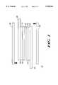
- FIG. 1is a side view of an electrochemical cell in accordance with the invention
- FIG. 2is a partial section view of an electrochemical cell as depicted in FIG. 1, having an improved tab structure, in accordance with the present invention.
- FIG. 3is a partial section view of an electrochemical cell having an improved tab structure, in accordance with an alternate embodiment of the present invention.
- FIG. 4is a partial section view of an electrochemical cell having an improved tab structure, in accordance with a further embodiment of the present invention.
- the cell 10includes first and second electrodes 12 and 14, respectively.
- the first electrode 12can be, for example, an anode in a lithium rechargeable cell.
- the anodemay be fabricated of any of a number of different known materials for lithium rechargeable cells, examples of which include metallic lithium, lithium alloys, and lithium intercalation materials such as carbon, petroleum coke, activated carbon, graphite, and other forms of carbon known in the art.
- the anode 12is fabricated of an amorphous carbonaceous material such as that disclosed in U.S. Pat. No. 5,647,963 issued on Jul. 15, 1997 to Zhang et al. for "Electrode Materials for Electrochemical Cells and Method for Making Same", assigned to Motorola, Inc., the disclosure of which is hereby incorporated by reference.
- the anode 12comprises a layer of active material 16, such as a carbon material as described hereinabove, deposited on a substrate 18.
- substrate 18can be any of a number of materials known in the art, examples of which include copper, gold, nickel, copper alloys, copper plated materials, and combinations thereof. In the embodiment of FIG. 1, the substrate 18 is fabricated of copper.
- the second electrode 14can be adapted to be the cathode of a lithium rechargeable cell.
- the cathodeis preferably fabricated of a lithium intercalation material, examples of which include lithiated manganese oxide, lithiated cobalt oxide, lithiated nickel oxide, and combinations thereof.
- the cathode 14is fabricated of a lithiated nickel oxide material such as is disclosed in commonly assigned U.S. Pat. No. 5,591,548 issued on Jan. 7, 1997 to Mao for "Positive Electrode Materials for Rechargeable Electrochemical Cells and Method of Making Same", the disclosure of which is hereby incorporated by reference.
- the cathode 14comprises a layer of the cathode active material 20 disposed on a cathode substrate 22.
- the cathode material 20may be such as that described hereinabove, while the substrate 22 may be fabricated from any of a number of known materials known in the art, examples of which include aluminum, nickel, and combinations thereof. In one preferred embodiment, substrate 22 is fabricated of aluminum.
- the electrolyte system 26preferably comprises an electrolyte active species and a polymer gel electrolyte support structure consisting of at least one or more different polymers.
- a first polymermay be provided as an absorbing phase
- the second polymermay be provided as an inert phase.
- the inert phasemay primarily provide mechanical integrity and structural rigidity to the electrolyte system
- the absorbing phasewhich can be disposed on either or both sides of the inert phase, is primarily adapted to engage the electrolyte active species therein.
- the absorbing phaseis preferably a gelling polymer and can further act as a bonding paste to assist in adhering the electrodes to the electrolyte system as described below.
- the electrolyte active speciesis a liquid or solid component (or both) which provides ionic conductivity between the anode 12 and the cathode 14.
- the electrolyte active speciesconsists of an alkali metal salt in a solvent.
- Typical alkali metal saltsinclude, but are not limited to, salts having the formula M + X - , where M + is an alkali metal cation such as Li + , Na + , K + , and combinations thereof, and where X 31 is an anion such as Cl - , Br - , I - , ClO 4 - , BF 4 - , PF 6 - , AsF 6 - , SbF 6 - , CH 3 CO 2 - , CF 3 SO 3 - , N(CF 3 SO 2 ) 2 - , C(CF 3 SO 2 ) 3 - , and combinations thereof.
- the solvent into which the salt is dispersedis typically an organic solvent including, but not limited to, propylene carbonate (PC), ethylene carbonate (EC), diethyl carbonate (DEC), dimethyl carbonate (DMC), dipropylcarbonate, dimethylsulfoxide, acetonitrile, dimethoxyethane, tetrahydrofuran, n-methyl-2-pyrrolidone (NMP), methyl ethyl ketone (MEK), acetone, and combinations thereof.
- PCpropylene carbonate
- ECethylene carbonate
- DECdiethyl carbonate
- DMCdimethyl carbonate
- dipropylcarbonatedimethylsulfoxide
- acetonitriledimethoxyethane
- NMPn-methyl-2-pyrrolidone
- MEKmethyl ethyl ketone
- acetoneand combinations thereof.
- electrolyte active speciesmay be used, such as KOH.
- first and second electrically conducting tabs 28 and 30Operatively connected and electrically coupled to said electrically conducting substrates 18 and 22 are first and second electrically conducting tabs 28 and 30.
- the function of tabs 28 and 30is to conduct current generated in the electrodes 12 and 14 to an application device, for example, a two-way radio device, and to recharge the cell.
- the tabs 28 and 30are generally fabricated of a metallic material, examples of which include stainless steel, iron, nickel, silver, aluminum, copper, and combinations thereof.
- the instant inventionis described herein as part of a lithium rechargeable electrochemical cell, it should be understood that it is not so limited.
- the electrolyte system and methods of fabricationare applicable to a host of different electrochemical systems, such as electrochromic devices, fuel cells, capacitors, and other types of energy storage systems, to name a few.
- the cell structurecan differ from that shown in FIG. 1.
- the cell 10could comprise multiple anode 12, cathode 14, and electrolyte 26 layers to essentially form several battery cells within a single battery package.
- the cell 10need not comprise stacked layers at all; instead, the electrode and electrolyte layers could be wound into a conventional "jelly roll" configuration in which tabs 28 and 30 extend from rolled electrodes.
- the entire electrochemical charge storage device 10is then packaged so that it is enclosed between first and second sheets of a metal foil laminate material 32 and 34.
- the device 10may be enclosed between first and second portions of a single sheet of a metal foil laminate. More particularly, the entire device 10, including the metallic tabs 28, 30, is enclosed in the metal foil laminate.
- the enclosing laminateshould provide a moisture and vapor barrier for the device, since moisture and oxygen will degrade the performance of many types of electrochemical devices. Therefore, the seal between the first and second sheets of the laminate, particularly around the tab region, should be hermetic. The seal and the elements which contribute to its hermetic nature will be discussed in greater detail hereinbelow.
- sheetsis not intended to be restrictive, since the packaging of the cell 10 according to the present invention can be accomplished using any form factor of metal foil laminate material.
- a form-fill-seal automated packaging schemecould be used in which the bottom portion of the packaging is formed into a cup-like shape into which the cell 10 is placed. The top portion, which could also be formed, is then heat sealed onto the bottom portion to form the sealed package.
- FIG. 2there is illustrated a side view of the electrochemical cell of FIG. 1 after sealing in a package.
- the metal foil laminate layers 32 and 34(FIG. 1) that enclose the cell 10 can, in fact, be multilayered laminate structures, e.g., including three (3) layers.
- both layers 32 and 34may include a first layer of a mechanically rugged or robust thermoplastic material 38, such as nylon, polyester, polypropylene, and combinations thereof.
- the purpose of layer 38is to provide strength and tear resistance for the foil laminate material. Accordingly, a host of other materials well known to those of ordinary skill in the art can also be used.
- the metal foil layer 40Disposed adjacent the thermoplastic layer 38 is a layer of a metal foil 40 that provides moisture and vapor barrier properties for the reasons described above. Accordingly, the metal foil layer 40 may be fabricated of a metal foil selected from the group of aluminum, copper, nickel, and combinations thereof.
- a layer of a heat-sealable polymer material 42disposed adjacent the metal foil layer 40.
- the purpose of the heat sealable polymer 42is to allow the two layers 32, 34 of metal foil laminate to be sealably closed together upon, for example, the application of heat. Due to the preferred heating regimes of the instant electrochemical device, the heat sealable polymer 42 is heat sealable at temperatures in the range of between 110 to 180° C., and preferably in the range of 120 to 170° C. Accordingly, the heat sealable plastic 42 is selected from the group of materials consisting of polypropylene, polyethylene, polyester, polyamides, and combinations thereof.
- FIG. 2illustrates the multilayered metal foil laminates 32 and 34 as each having the same three sub-layers
- the inventionis not so limited. Either or both layers may have more or less sub-layers, made up of the same or different materials.
- either or both layers 32, 34could be fabricated of a single layer of material that provides the same functionality of the tri-layer structure described above.
- a layer of insulating adhesive tape 29is provided on the opposing major surfaces of metallic tab 28.
- the same structureis provided for each metallic tab; however, for illustrative purposes, only tab 28 is shown.
- the insulative tapeis preferably constructed from a modified polyolefin material similar to that used to seal the periphery of multilayered foil laminates 32 and 34.
- the modified polyolefinshould preferably have a sealing/melting temperature in the range of between 110-180° C., and preferably between 120-170° C.
- preferred materials from which to fabricate the insulative tape 29include polypropylene-maleic anhydride copolymer, polypropylene-ethylene acrylic acid copolymer, polyester, and combinations thereof.
- Unite®which is a polypropylene-maleic anhydride copolymer fabricated by Aristech
- Thermo-Bond Film 845which is a modified polypropylene by 3M
- Thermo-Bond Film 667which is a polyester thermoplastic by 3M.
- Metal foil laminate layer 32 and tape layer 29have concentric apertures which, together, expose the surface of tab member 28 for subsequent welding, e.g., resistance welding of the tab member to external circuitry.
- the insulative tape 29have a smaller diameter opening than the foil laminate 32. It will occur to one skilled in the art that the shape of the apertures is not of critical importance. Thus, even though circular openings are assumed for discussion purposes, the invention is not so limited.
- apertures which expose the tab surface(s)precludes the need for tabs which extend beyond the inside of the package; as a result, insufficient tab strength is no longer an issue. Furthermore, tab-to-tab shorting is precluded since the tabs do not extend beyond the internal portion of the package.
- the package layeringis symmetric about the tab members.
- apertures 60 and 62which are counterparts to apertures 50 and 52, expose the opposing side of tab member 28. This structure is preferred in instances in which resistance welding is to be used, since resistance welding often requires simultaneous contact with both the top and bottom surfaces of the tab member 28.
- an alternate embodiment of our inventionexposes only a single major surface of the tab member 28.
- This embodimentis preferable in instances in which, for example, either ultrasonic or laser welding of the metal foil package to an external circuit is to be performed. Since only a single side of the tab need be exposed, insulative tape is only required along a single surface of the tab 28, i.e., the surface to be welded to.
- FIG. 4a further embodiment incorporates a structure which is identical to the structure illustrated in FIG. 3, save for an additional layer of insulative seal tape 29 disposed above outer layer 38.
- This structureis preferable in instances in which, for example, electrical leads extending from external circuitry are not insulated and, thus, could potentially short to metallic foil layer 40.
- An advantage of the present inventionis that metal foil laminates can be used to seal a battery cell while avoiding the tab-related issues which have plagued prior art structures. Most notably, tab breakage, due primarily to poor tab strength, has been eliminated without the need to increase tab thickness and without having to provide an additional coating to improve tab strength. Finally, with the tabs fixed apart from each other, tab-to-tab shorting issues have been virtually eliminated.
Landscapes
- Chemical & Material Sciences (AREA)
- Chemical Kinetics & Catalysis (AREA)
- Electrochemistry (AREA)
- General Chemical & Material Sciences (AREA)
- Inorganic Chemistry (AREA)
- Sealing Battery Cases Or Jackets (AREA)
Abstract
Description
Claims (12)
Priority Applications (1)
| Application Number | Priority Date | Filing Date | Title |
|---|---|---|---|
| US08/963,324US5948562A (en) | 1997-11-03 | 1997-11-03 | Energy storage device |
Applications Claiming Priority (1)
| Application Number | Priority Date | Filing Date | Title |
|---|---|---|---|
| US08/963,324US5948562A (en) | 1997-11-03 | 1997-11-03 | Energy storage device |
Publications (1)
| Publication Number | Publication Date |
|---|---|
| US5948562Atrue US5948562A (en) | 1999-09-07 |
Family
ID=25507076
Family Applications (1)
| Application Number | Title | Priority Date | Filing Date |
|---|---|---|---|
| US08/963,324Expired - LifetimeUS5948562A (en) | 1997-11-03 | 1997-11-03 | Energy storage device |
Country Status (1)
| Country | Link |
|---|---|
| US (1) | US5948562A (en) |
Cited By (57)
| Publication number | Priority date | Publication date | Assignee | Title |
|---|---|---|---|---|
| US6120935A (en)* | 1997-02-18 | 2000-09-19 | U.S. Philips Corporation | Flat accumulator device having an electrochemical cell and electrical contacts |
| US6245457B1 (en)* | 1999-06-11 | 2001-06-12 | Alcatel | Bussing structure in an electrochemical cell |
| WO2002047099A1 (en)* | 2000-12-09 | 2002-06-13 | Energy Storage Systems Pty Ltd | A connection between a conductive substrate and a laminate |
| US6420071B1 (en)* | 2000-03-21 | 2002-07-16 | Midwest Research Institute | Method for improving the durability of ion insertion materials |
| WO2002047184A3 (en)* | 2000-12-05 | 2002-08-29 | Danionics As | Electrochemical cells and their packaging |
| US6531246B2 (en)* | 1999-05-14 | 2003-03-11 | Mitsubishi Denki Kabushiki Kaisha | Plate-shaped battery and battery apparatus |
| US6552895B1 (en)* | 1998-09-16 | 2003-04-22 | Energy Storage Systems Pty Ltd | Flexible charge storage device |
| US6576365B1 (en) | 1999-12-06 | 2003-06-10 | E.C.R. - Electro Chemical Research Ltd. | Ultra-thin electrochemical energy storage devices |
| WO2003026039A3 (en)* | 2001-09-21 | 2003-07-10 | Eveready Battery Inc | Flexible thin battery and method of manufacturing the same |
| US20030193317A1 (en)* | 2002-04-11 | 2003-10-16 | Nissan Motor Co., Ltd. | Battery and related method |
| US20030224246A1 (en)* | 2002-06-03 | 2003-12-04 | Nissan Motor Co., Ltd. | Battery and related method |
| US6664619B2 (en)* | 2001-10-11 | 2003-12-16 | Nec Tokin Corporation | Laminate film packaged storage device and fabricating method thereof |
| WO2003065536A3 (en)* | 2002-01-25 | 2004-01-29 | Engen Group Inc | Polymer-modified electrode for energy storage devices and electrochemical supercapacitor based on said polymer-modified electrode |
| US20040065080A1 (en)* | 2002-10-04 | 2004-04-08 | Fasca Ted S. | Energy storage system and method |
| US20040081778A1 (en)* | 2000-07-10 | 2004-04-29 | Pynenburg Rory Albert James | Laminate package for an energy storage device |
| US6790556B1 (en) | 1999-12-06 | 2004-09-14 | E.C.R. - Electro Chemical Research, Ltd. | Electrochemical energy storage device having improved enclosure arrangement |
| US20050031953A1 (en)* | 2003-08-08 | 2005-02-10 | Nissan Motor Co., Ltd. | Bipolar battery, assembled battery, combination assembled battery, and vehicle using the assembled battery or the combination assembled battery |
| US20050112461A1 (en)* | 2001-03-01 | 2005-05-26 | The University Of Chicago | Packaging for primary and secondary batteries |
| US20070099076A1 (en)* | 2005-10-27 | 2007-05-03 | Sanyo Electric Co., Ltd. | Cell having film outer casing |
| EP1804327A1 (en)* | 2005-12-29 | 2007-07-04 | Samsung SDI Co., Ltd. | Lithium ion secondary battery |
| US20070154789A1 (en)* | 2005-12-29 | 2007-07-05 | Chang Seok-Gyun | Lithium ion rechargeable battery |
| US7292431B2 (en)* | 2002-10-03 | 2007-11-06 | Gen 3 Partners, Inc. | Electrochemical capacitor and method of use |
| WO2010094314A1 (en)* | 2009-02-23 | 2010-08-26 | Li-Tec Battery Gmbh | Galvanic cell |
| CN101488588B (en)* | 2005-12-29 | 2011-05-25 | 三星Sdi株式会社 | Lithium-ion secondary battery |
| US7959769B2 (en) | 2004-12-08 | 2011-06-14 | Infinite Power Solutions, Inc. | Deposition of LiCoO2 |
| US7993773B2 (en) | 2002-08-09 | 2011-08-09 | Infinite Power Solutions, Inc. | Electrochemical apparatus with barrier layer protected substrate |
| US8021778B2 (en) | 2002-08-09 | 2011-09-20 | Infinite Power Solutions, Inc. | Electrochemical apparatus with barrier layer protected substrate |
| US8062708B2 (en) | 2006-09-29 | 2011-11-22 | Infinite Power Solutions, Inc. | Masking of and material constraint for depositing battery layers on flexible substrates |
| WO2012030080A3 (en)* | 2010-08-30 | 2012-05-03 | 주식회사 엘지화학 | Rechargeable battery having a novel structure |
| US8197781B2 (en) | 2006-11-07 | 2012-06-12 | Infinite Power Solutions, Inc. | Sputtering target of Li3PO4 and method for producing same |
| US8236443B2 (en) | 2002-08-09 | 2012-08-07 | Infinite Power Solutions, Inc. | Metal film encapsulation |
| US8260203B2 (en) | 2008-09-12 | 2012-09-04 | Infinite Power Solutions, Inc. | Energy device with integral conductive surface for data communication via electromagnetic energy and method thereof |
| US8268488B2 (en) | 2007-12-21 | 2012-09-18 | Infinite Power Solutions, Inc. | Thin film electrolyte for thin film batteries |
| US8350519B2 (en) | 2008-04-02 | 2013-01-08 | Infinite Power Solutions, Inc | Passive over/under voltage control and protection for energy storage devices associated with energy harvesting |
| US8394522B2 (en) | 2002-08-09 | 2013-03-12 | Infinite Power Solutions, Inc. | Robust metal film encapsulation |
| US8404376B2 (en) | 2002-08-09 | 2013-03-26 | Infinite Power Solutions, Inc. | Metal film encapsulation |
| US8431264B2 (en) | 2002-08-09 | 2013-04-30 | Infinite Power Solutions, Inc. | Hybrid thin-film battery |
| US8445130B2 (en) | 2002-08-09 | 2013-05-21 | Infinite Power Solutions, Inc. | Hybrid thin-film battery |
| US8508193B2 (en) | 2008-10-08 | 2013-08-13 | Infinite Power Solutions, Inc. | Environmentally-powered wireless sensor module |
| US8518581B2 (en) | 2008-01-11 | 2013-08-27 | Inifinite Power Solutions, Inc. | Thin film encapsulation for thin film batteries and other devices |
| US8599572B2 (en) | 2009-09-01 | 2013-12-03 | Infinite Power Solutions, Inc. | Printed circuit board with integrated thin film battery |
| US8636876B2 (en) | 2004-12-08 | 2014-01-28 | R. Ernest Demaray | Deposition of LiCoO2 |
| US8728285B2 (en) | 2003-05-23 | 2014-05-20 | Demaray, Llc | Transparent conductive oxides |
| US8906523B2 (en) | 2008-08-11 | 2014-12-09 | Infinite Power Solutions, Inc. | Energy device with integral collector surface for electromagnetic energy harvesting and method thereof |
| US20150079448A1 (en)* | 2013-09-17 | 2015-03-19 | Kabushiki Kaisha Toshiba | Nonaqueous electrolyte battery |
| WO2015103295A1 (en)* | 2013-12-30 | 2015-07-09 | Moomaw Daniel | Sealed bipolar battery assembly |
| US9334557B2 (en) | 2007-12-21 | 2016-05-10 | Sapurast Research Llc | Method for sputter targets for electrolyte films |
| US9634296B2 (en) | 2002-08-09 | 2017-04-25 | Sapurast Research Llc | Thin film battery on an integrated circuit or circuit board and method thereof |
| US9859536B2 (en) | 2013-12-26 | 2018-01-02 | Kabushiki Kaisha Toshiba | Nonaqueous electrolyte battery including a sealed case, battery pack and storage battery apparatus |
| KR20180041530A (en)* | 2016-10-14 | 2018-04-24 | 주식회사 엘지화학 | Secondary battery including electrode lead |
| US10090515B2 (en) | 2011-05-11 | 2018-10-02 | Gridtential Energy, Inc. | Bipolar hybrid energy storage device |
| US10290904B2 (en) | 2011-05-11 | 2019-05-14 | Gridtential Energy, Inc. | Wafer-based bipolar battery plate |
| CN109964362A (en)* | 2017-03-21 | 2019-07-02 | 株式会社Lg化学 | Battery module with simple sensing structure |
| US10680277B2 (en) | 2010-06-07 | 2020-06-09 | Sapurast Research Llc | Rechargeable, high-density electrochemical device |
| EP4068448A1 (en)* | 2021-03-31 | 2022-10-05 | Toyota Jidosha Kabushiki Kaisha | Power storage cell, power storage device, and method for manufacturing power storage device |
| WO2024096711A1 (en)* | 2022-11-04 | 2024-05-10 | 주식회사 엘지에너지솔루션 | Secondary battery |
| FR3155967A1 (en)* | 2023-11-24 | 2025-05-30 | AMPERE s.a.s | Pouch-type electrochemical cell for storing electrical energy |
Citations (3)
| Publication number | Priority date | Publication date | Assignee | Title |
|---|---|---|---|---|
| US4278744A (en)* | 1975-12-19 | 1981-07-14 | Duracell International Inc. | Expandable casing for electro-chemical cells |
| US5227264A (en)* | 1991-02-14 | 1993-07-13 | Hydro-Quebec | Device for packaging a lithium battery |
| US5650243A (en)* | 1996-01-16 | 1997-07-22 | Ferment; George R. | Battery packaging construction using flexible plastic barrier structures |
- 1997
- 1997-11-03USUS08/963,324patent/US5948562A/ennot_activeExpired - Lifetime
Patent Citations (3)
| Publication number | Priority date | Publication date | Assignee | Title |
|---|---|---|---|---|
| US4278744A (en)* | 1975-12-19 | 1981-07-14 | Duracell International Inc. | Expandable casing for electro-chemical cells |
| US5227264A (en)* | 1991-02-14 | 1993-07-13 | Hydro-Quebec | Device for packaging a lithium battery |
| US5650243A (en)* | 1996-01-16 | 1997-07-22 | Ferment; George R. | Battery packaging construction using flexible plastic barrier structures |
Cited By (98)
| Publication number | Priority date | Publication date | Assignee | Title |
|---|---|---|---|---|
| US6120935A (en)* | 1997-02-18 | 2000-09-19 | U.S. Philips Corporation | Flat accumulator device having an electrochemical cell and electrical contacts |
| EP1133781A4 (en)* | 1998-09-16 | 2007-01-10 | A flexible charge storage device | |
| US6552895B1 (en)* | 1998-09-16 | 2003-04-22 | Energy Storage Systems Pty Ltd | Flexible charge storage device |
| US6531246B2 (en)* | 1999-05-14 | 2003-03-11 | Mitsubishi Denki Kabushiki Kaisha | Plate-shaped battery and battery apparatus |
| US6245457B1 (en)* | 1999-06-11 | 2001-06-12 | Alcatel | Bussing structure in an electrochemical cell |
| DE10085271B3 (en)* | 1999-12-06 | 2017-06-14 | Avx Corporation | Electrochemical energy storage device with improved housing arrangement |
| US7687198B2 (en) | 1999-12-06 | 2010-03-30 | E.C.R.-Electro Chemical Research Ltd. | Electrochemical energy storage device |
| US6576365B1 (en) | 1999-12-06 | 2003-06-10 | E.C.R. - Electro Chemical Research Ltd. | Ultra-thin electrochemical energy storage devices |
| US7927736B2 (en) | 1999-12-06 | 2011-04-19 | E.C.R.-Electro Chemical Research Ltd. | Electrochemical energy storage device |
| US7410725B2 (en) | 1999-12-06 | 2008-08-12 | Avx Corporation | Electrochemical energy storage device having improved enclosure arrangement |
| US20080090141A1 (en)* | 1999-12-06 | 2008-04-17 | Arieh Meitav | Electrochemical energy storage device |
| US20050031954A1 (en)* | 1999-12-06 | 2005-02-10 | Arieh Meitav | Electrochemical energy storage device having improved enclosure arrangement |
| US20100047683A1 (en)* | 1999-12-06 | 2010-02-25 | E.C.R.-Electro Chemical Research, Ltd. | Electrochemical energy storage device |
| US6790556B1 (en) | 1999-12-06 | 2004-09-14 | E.C.R. - Electro Chemical Research, Ltd. | Electrochemical energy storage device having improved enclosure arrangement |
| US6420071B1 (en)* | 2000-03-21 | 2002-07-16 | Midwest Research Institute | Method for improving the durability of ion insertion materials |
| US20040081778A1 (en)* | 2000-07-10 | 2004-04-29 | Pynenburg Rory Albert James | Laminate package for an energy storage device |
| EP1317759A4 (en)* | 2000-07-10 | 2007-07-18 | Cap Xx Ltd | Laminate package for an energy storage device |
| US20040115528A1 (en)* | 2000-12-05 | 2004-06-17 | Helmich Karl Jorgen | Electrochemical cells and their packaging |
| WO2002047184A3 (en)* | 2000-12-05 | 2002-08-29 | Danionics As | Electrochemical cells and their packaging |
| US20040076877A1 (en)* | 2000-12-09 | 2004-04-22 | James David Albert | Connection between a conductive substrate and laminate |
| US7595131B2 (en)* | 2000-12-09 | 2009-09-29 | Cap-Xx Limited | Connection between a conductive substrate and a laminate |
| WO2002047099A1 (en)* | 2000-12-09 | 2002-06-13 | Energy Storage Systems Pty Ltd | A connection between a conductive substrate and a laminate |
| US20050112461A1 (en)* | 2001-03-01 | 2005-05-26 | The University Of Chicago | Packaging for primary and secondary batteries |
| US6838209B2 (en) | 2001-09-21 | 2005-01-04 | Eveready Battery Company, Inc. | Flexible thin battery and method of manufacturing same |
| WO2003026039A3 (en)* | 2001-09-21 | 2003-07-10 | Eveready Battery Inc | Flexible thin battery and method of manufacturing the same |
| US6664619B2 (en)* | 2001-10-11 | 2003-12-16 | Nec Tokin Corporation | Laminate film packaged storage device and fabricating method thereof |
| US6795293B2 (en) | 2002-01-25 | 2004-09-21 | Engen Group, Inc. | Polymer-modified electrode for energy storage devices and electrochemical supercapacitor based on said polymer-modified electrode |
| US20040057191A1 (en)* | 2002-01-25 | 2004-03-25 | Alexander Timonov | Polymer-modified electrode for energy storage devices and electrochemical supercapacitor based on said polymer-modified electrode |
| WO2003065536A3 (en)* | 2002-01-25 | 2004-01-29 | Engen Group Inc | Polymer-modified electrode for energy storage devices and electrochemical supercapacitor based on said polymer-modified electrode |
| US20030193317A1 (en)* | 2002-04-11 | 2003-10-16 | Nissan Motor Co., Ltd. | Battery and related method |
| US7008720B2 (en)* | 2002-04-11 | 2006-03-07 | Nissan Motor Co., Ltd. | Battery having a terminal lead surface covering layer and related method |
| EP1353389A3 (en)* | 2002-04-11 | 2005-03-09 | Nissan Motor Co., Ltd. | Battery and method of its manufacture |
| EP1796186A1 (en)* | 2002-06-03 | 2007-06-13 | Nissan Motor Co., Ltd. | Battery and related method |
| US7276313B2 (en) | 2002-06-03 | 2007-10-02 | Nissan Motor Co., Ltd. | Battery and related method |
| EP1376718A3 (en)* | 2002-06-03 | 2004-06-23 | Nissan Motor Co., Ltd. | Battery and related method |
| US20030224246A1 (en)* | 2002-06-03 | 2003-12-04 | Nissan Motor Co., Ltd. | Battery and related method |
| US8021778B2 (en) | 2002-08-09 | 2011-09-20 | Infinite Power Solutions, Inc. | Electrochemical apparatus with barrier layer protected substrate |
| US8404376B2 (en) | 2002-08-09 | 2013-03-26 | Infinite Power Solutions, Inc. | Metal film encapsulation |
| US9634296B2 (en) | 2002-08-09 | 2017-04-25 | Sapurast Research Llc | Thin film battery on an integrated circuit or circuit board and method thereof |
| US8394522B2 (en) | 2002-08-09 | 2013-03-12 | Infinite Power Solutions, Inc. | Robust metal film encapsulation |
| US8236443B2 (en) | 2002-08-09 | 2012-08-07 | Infinite Power Solutions, Inc. | Metal film encapsulation |
| US9793523B2 (en) | 2002-08-09 | 2017-10-17 | Sapurast Research Llc | Electrochemical apparatus with barrier layer protected substrate |
| US8431264B2 (en) | 2002-08-09 | 2013-04-30 | Infinite Power Solutions, Inc. | Hybrid thin-film battery |
| US8445130B2 (en) | 2002-08-09 | 2013-05-21 | Infinite Power Solutions, Inc. | Hybrid thin-film battery |
| US8535396B2 (en) | 2002-08-09 | 2013-09-17 | Infinite Power Solutions, Inc. | Electrochemical apparatus with barrier layer protected substrate |
| US7993773B2 (en) | 2002-08-09 | 2011-08-09 | Infinite Power Solutions, Inc. | Electrochemical apparatus with barrier layer protected substrate |
| US7292431B2 (en)* | 2002-10-03 | 2007-11-06 | Gen 3 Partners, Inc. | Electrochemical capacitor and method of use |
| US20040065080A1 (en)* | 2002-10-04 | 2004-04-08 | Fasca Ted S. | Energy storage system and method |
| US8728285B2 (en) | 2003-05-23 | 2014-05-20 | Demaray, Llc | Transparent conductive oxides |
| US20050031953A1 (en)* | 2003-08-08 | 2005-02-10 | Nissan Motor Co., Ltd. | Bipolar battery, assembled battery, combination assembled battery, and vehicle using the assembled battery or the combination assembled battery |
| EP1505669A3 (en)* | 2003-08-08 | 2008-07-09 | Nissan Motor Co., Ltd. | Bipolar battery with laminate films and resin layer. |
| US7501206B2 (en)* | 2003-08-08 | 2009-03-10 | Nissan Motor Co., Ltd. | Bipolar battery, assembled battery, combination assembled battery, and vehicle using the assembled battery or the combination assembled battery |
| US7959769B2 (en) | 2004-12-08 | 2011-06-14 | Infinite Power Solutions, Inc. | Deposition of LiCoO2 |
| US8636876B2 (en) | 2004-12-08 | 2014-01-28 | R. Ernest Demaray | Deposition of LiCoO2 |
| US20070099076A1 (en)* | 2005-10-27 | 2007-05-03 | Sanyo Electric Co., Ltd. | Cell having film outer casing |
| US7704636B2 (en)* | 2005-10-27 | 2010-04-27 | Sanyo Electric Co., Ltd. | Cell having film outer casing |
| CN101488588B (en)* | 2005-12-29 | 2011-05-25 | 三星Sdi株式会社 | Lithium-ion secondary battery |
| US20070154789A1 (en)* | 2005-12-29 | 2007-07-05 | Chang Seok-Gyun | Lithium ion rechargeable battery |
| EP1804327A1 (en)* | 2005-12-29 | 2007-07-04 | Samsung SDI Co., Ltd. | Lithium ion secondary battery |
| US8053101B2 (en) | 2005-12-29 | 2011-11-08 | Samsung Sdi Co., Ltd. | Lithium ion rechargeable battery |
| US8062708B2 (en) | 2006-09-29 | 2011-11-22 | Infinite Power Solutions, Inc. | Masking of and material constraint for depositing battery layers on flexible substrates |
| US8197781B2 (en) | 2006-11-07 | 2012-06-12 | Infinite Power Solutions, Inc. | Sputtering target of Li3PO4 and method for producing same |
| US9334557B2 (en) | 2007-12-21 | 2016-05-10 | Sapurast Research Llc | Method for sputter targets for electrolyte films |
| US8268488B2 (en) | 2007-12-21 | 2012-09-18 | Infinite Power Solutions, Inc. | Thin film electrolyte for thin film batteries |
| US8518581B2 (en) | 2008-01-11 | 2013-08-27 | Inifinite Power Solutions, Inc. | Thin film encapsulation for thin film batteries and other devices |
| US9786873B2 (en) | 2008-01-11 | 2017-10-10 | Sapurast Research Llc | Thin film encapsulation for thin film batteries and other devices |
| US8350519B2 (en) | 2008-04-02 | 2013-01-08 | Infinite Power Solutions, Inc | Passive over/under voltage control and protection for energy storage devices associated with energy harvesting |
| US8906523B2 (en) | 2008-08-11 | 2014-12-09 | Infinite Power Solutions, Inc. | Energy device with integral collector surface for electromagnetic energy harvesting and method thereof |
| US8260203B2 (en) | 2008-09-12 | 2012-09-04 | Infinite Power Solutions, Inc. | Energy device with integral conductive surface for data communication via electromagnetic energy and method thereof |
| US8508193B2 (en) | 2008-10-08 | 2013-08-13 | Infinite Power Solutions, Inc. | Environmentally-powered wireless sensor module |
| CN102326275A (en)* | 2009-02-23 | 2012-01-18 | 锂电池科技有限公司 | Galvanic cell |
| WO2010094314A1 (en)* | 2009-02-23 | 2010-08-26 | Li-Tec Battery Gmbh | Galvanic cell |
| US9532453B2 (en) | 2009-09-01 | 2016-12-27 | Sapurast Research Llc | Printed circuit board with integrated thin film battery |
| US8599572B2 (en) | 2009-09-01 | 2013-12-03 | Infinite Power Solutions, Inc. | Printed circuit board with integrated thin film battery |
| US10680277B2 (en) | 2010-06-07 | 2020-06-09 | Sapurast Research Llc | Rechargeable, high-density electrochemical device |
| WO2012030080A3 (en)* | 2010-08-30 | 2012-05-03 | 주식회사 엘지화학 | Rechargeable battery having a novel structure |
| US9005805B2 (en) | 2010-08-30 | 2015-04-14 | Lg Chem, Ltd. | Secondary battery of novel structure |
| US9385350B2 (en) | 2010-08-30 | 2016-07-05 | Lg Chem, Ltd. | Secondary battery of novel structure |
| US10090515B2 (en) | 2011-05-11 | 2018-10-02 | Gridtential Energy, Inc. | Bipolar hybrid energy storage device |
| US10290904B2 (en) | 2011-05-11 | 2019-05-14 | Gridtential Energy, Inc. | Wafer-based bipolar battery plate |
| US20150079448A1 (en)* | 2013-09-17 | 2015-03-19 | Kabushiki Kaisha Toshiba | Nonaqueous electrolyte battery |
| US9859536B2 (en) | 2013-12-26 | 2018-01-02 | Kabushiki Kaisha Toshiba | Nonaqueous electrolyte battery including a sealed case, battery pack and storage battery apparatus |
| US10797276B2 (en)* | 2013-12-30 | 2020-10-06 | Gridtential Energy, Inc. | Sealed bipolar battery assembly |
| WO2015103295A1 (en)* | 2013-12-30 | 2015-07-09 | Moomaw Daniel | Sealed bipolar battery assembly |
| US20160329535A1 (en)* | 2013-12-30 | 2016-11-10 | Gridtential Energy, Inc | Sealed bipolar battery assembly |
| US11114686B2 (en) | 2016-10-14 | 2021-09-07 | Lg Chem, Ltd. | Secondary battery including electrode lead exposed within the sealing part and method for manufacturing the same |
| JP2019505968A (en)* | 2016-10-14 | 2019-02-28 | エルジー・ケム・リミテッド | Secondary battery including electrode lead and method for manufacturing the secondary battery |
| EP3385998A4 (en)* | 2016-10-14 | 2019-01-30 | LG Chem, Ltd. | Secondary battery comprising electrode lead and method for manufacturing secondary battery |
| CN108463900A (en)* | 2016-10-14 | 2018-08-28 | 株式会社Lg化学 | Secondary battery including electrode lead and method of manufacturing secondary battery |
| CN108463900B (en)* | 2016-10-14 | 2020-12-22 | 株式会社Lg化学 | Secondary battery including electrode lead and method of manufacturing secondary battery |
| KR20180041530A (en)* | 2016-10-14 | 2018-04-24 | 주식회사 엘지화학 | Secondary battery including electrode lead |
| US11588170B2 (en) | 2016-10-14 | 2023-02-21 | Lg Energy Solution, Ltd. | Secondary battery including electrode lead exposed within the sealing part and method for manufacturing the same |
| CN109964362A (en)* | 2017-03-21 | 2019-07-02 | 株式会社Lg化学 | Battery module with simple sensing structure |
| CN109964362B (en)* | 2017-03-21 | 2024-02-06 | 株式会社Lg新能源 | Battery module with simple sensing structure |
| EP3483980B1 (en)* | 2017-03-21 | 2025-06-04 | LG Energy Solution, Ltd. | Battery module having simple sensing structure |
| EP4068448A1 (en)* | 2021-03-31 | 2022-10-05 | Toyota Jidosha Kabushiki Kaisha | Power storage cell, power storage device, and method for manufacturing power storage device |
| WO2024096711A1 (en)* | 2022-11-04 | 2024-05-10 | 주식회사 엘지에너지솔루션 | Secondary battery |
| FR3155967A1 (en)* | 2023-11-24 | 2025-05-30 | AMPERE s.a.s | Pouch-type electrochemical cell for storing electrical energy |
Similar Documents
| Publication | Publication Date | Title |
|---|---|---|
| US5948562A (en) | Energy storage device | |
| EP0834934A1 (en) | Non-aqueous electrolyte cell | |
| US20230057980A1 (en) | Secondary battery and method for manufacturing the same | |
| US20060216593A1 (en) | Lithium rechargeable battery | |
| JP2001118547A (en) | Package | |
| US20220166071A1 (en) | Secondary battery | |
| JPH10289696A (en) | Battery and its manufacture | |
| JPH11250873A (en) | Nonaqueous electrolyte secondary battery | |
| JP2005310402A (en) | Bipolar battery, battery pack, and vehicle equipped with these | |
| JP3579227B2 (en) | Thin rechargeable battery | |
| US20230369652A1 (en) | Secondary battery and method of manufacturing secondary battery | |
| WO2021140838A1 (en) | Secondary battery | |
| US20230207988A1 (en) | Secondary battery and method of manufacturing the same | |
| JP2020173890A (en) | Assembled battery and manufacturing method thereof | |
| US20190334210A1 (en) | Secondary battery | |
| JP7043754B2 (en) | Lead member and power storage device | |
| JP3601283B2 (en) | Non-aqueous electrolyte battery | |
| CN101286550B (en) | Battery package and secondary battery including the same | |
| US11411241B2 (en) | Secondary battery | |
| US11387493B2 (en) | Secondary battery | |
| US11929467B2 (en) | Secondary battery | |
| US12034127B2 (en) | Secondary battery | |
| US20250006932A1 (en) | Secondary battery | |
| US20240266678A1 (en) | Secondary battery | |
| US20240170731A1 (en) | Secondary battery and method of manufacturing the same |
Legal Events
| Date | Code | Title | Description |
|---|---|---|---|
| AS | Assignment | Owner name:MOTOROLA, INC., A CORP. OF DELAWARE, ILLINOIS Free format text:ASSIGNMENT OF ASSIGNORS INTEREST;ASSIGNORS:FULCHER, MICHAEL;GIES, PAUL;HASSENZAHL, STEVEN L.;REEL/FRAME:008804/0705 Effective date:19971031 | |
| STCF | Information on status: patent grant | Free format text:PATENTED CASE | |
| FPAY | Fee payment | Year of fee payment:4 | |
| FPAY | Fee payment | Year of fee payment:8 | |
| AS | Assignment | Owner name:MOTOROLA MOBILITY, INC, ILLINOIS Free format text:ASSIGNMENT OF ASSIGNORS INTEREST;ASSIGNOR:MOTOROLA, INC;REEL/FRAME:025673/0558 Effective date:20100731 | |
| FPAY | Fee payment | Year of fee payment:12 | |
| AS | Assignment | Owner name:MOTOROLA MOBILITY LLC, ILLINOIS Free format text:CHANGE OF NAME;ASSIGNOR:MOTOROLA MOBILITY, INC.;REEL/FRAME:029216/0282 Effective date:20120622 | |
| AS | Assignment | Owner name:GOOGLE TECHNOLOGY HOLDINGS LLC, CALIFORNIA Free format text:ASSIGNMENT OF ASSIGNORS INTEREST;ASSIGNOR:MOTOROLA MOBILITY LLC;REEL/FRAME:034471/0268 Effective date:20141028 | |
| AS | Assignment | Owner name:AMPEREX TECHNOLOGY LIMITED, HONG KONG Free format text:ASSIGNMENT OF ASSIGNORS INTEREST;ASSIGNOR:GOOGLE TECHNOLOGY HOLDINGS LLC;REEL/FRAME:046392/0764 Effective date:20180604 |