US5948055A - Distributed internet monitoring system and method - Google Patents
Distributed internet monitoring system and methodDownload PDFInfo
- Publication number
- US5948055A US5948055AUS08/705,358US70535896AUS5948055AUS 5948055 AUS5948055 AUS 5948055AUS 70535896 AUS70535896 AUS 70535896AUS 5948055 AUS5948055 AUS 5948055A
- Authority
- US
- United States
- Prior art keywords
- block
- topology
- action
- topology data
- network
- Prior art date
- Legal status (The legal status is an assumption and is not a legal conclusion. Google has not performed a legal analysis and makes no representation as to the accuracy of the status listed.)
- Expired - Lifetime
Links
- 238000012544monitoring processMethods0.000titleclaimsabstractdescription49
- 238000000034methodMethods0.000titleclaimsdescription120
- 230000007246mechanismEffects0.000claimsabstractdescription29
- 230000009471actionEffects0.000claimsdescription237
- 238000004891communicationMethods0.000claimsdescription27
- 230000004044responseEffects0.000claimsdescription18
- 238000012545processingMethods0.000claimsdescription8
- 238000012546transferMethods0.000description303
- 238000007726management methodMethods0.000description63
- 230000008569processEffects0.000description50
- 230000008859changeEffects0.000description19
- 230000008901benefitEffects0.000description12
- 238000010586diagramMethods0.000description11
- 230000000875corresponding effectEffects0.000description8
- 238000012217deletionMethods0.000description6
- 230000037430deletionEffects0.000description6
- 238000012163sequencing techniqueMethods0.000description5
- 238000013461designMethods0.000description3
- 230000001360synchronised effectEffects0.000description3
- 230000006870functionEffects0.000description2
- 230000036541healthEffects0.000description2
- 238000012986modificationMethods0.000description2
- 230000004048modificationEffects0.000description2
- 238000005457optimizationMethods0.000description2
- 230000003068static effectEffects0.000description2
- 230000001960triggered effectEffects0.000description2
- 238000010200validation analysisMethods0.000description2
- 241001522296Erithacus rubeculaSpecies0.000description1
- 238000004458analytical methodMethods0.000description1
- 238000013459approachMethods0.000description1
- 230000005540biological transmissionEffects0.000description1
- 238000004590computer programMethods0.000description1
- 230000001276controlling effectEffects0.000description1
- 238000013499data modelMethods0.000description1
- 238000013500data storageMethods0.000description1
- 230000007123defenseEffects0.000description1
- 230000007812deficiencyEffects0.000description1
- 238000001514detection methodMethods0.000description1
- 230000000977initiatory effectEffects0.000description1
- 230000003993interactionEffects0.000description1
- 238000004519manufacturing processMethods0.000description1
- 230000003287optical effectEffects0.000description1
- 230000008520organizationEffects0.000description1
- 238000005192partitionMethods0.000description1
- 238000007781pre-processingMethods0.000description1
- 238000004886process controlMethods0.000description1
- 230000010076replicationEffects0.000description1
- 238000003860storageMethods0.000description1
Images


Classifications
- H—ELECTRICITY
- H04—ELECTRIC COMMUNICATION TECHNIQUE
- H04L—TRANSMISSION OF DIGITAL INFORMATION, e.g. TELEGRAPHIC COMMUNICATION
- H04L41/00—Arrangements for maintenance, administration or management of data switching networks, e.g. of packet switching networks
- H04L41/12—Discovery or management of network topologies
- H—ELECTRICITY
- H04—ELECTRIC COMMUNICATION TECHNIQUE
- H04L—TRANSMISSION OF DIGITAL INFORMATION, e.g. TELEGRAPHIC COMMUNICATION
- H04L41/00—Arrangements for maintenance, administration or management of data switching networks, e.g. of packet switching networks
- H04L41/22—Arrangements for maintenance, administration or management of data switching networks, e.g. of packet switching networks comprising specially adapted graphical user interfaces [GUI]
Definitions
- the present inventionsgenerally relates to data communication networks and, more particularly, to a distributed internet monitoring system and method for permitting high performance generation of a network management map of a data communication network by using a plurality of stations to monitor and exchange data regarding the network.
- a data communications networkgenerally includes a group of devices, for instance, computers, repeaters, bridges, routers, etc., situated at network nodes and a collection of communication channels for interconnecting the various nodes. Hardware and software associated with the network and particularly the devices permit the devices to exchange data electronically via the communication channels.
- a local area networkis a network of devices in close proximity, typically less than one mile, and usually connected by a single cable, for instance, a coaxial cable.
- a wide area networkis a network of devices which are separated by longer distances, often connected by, for example, telephone lines or satellite links. In fact, some WANs span the U.S. as well as the world. Furthermore, many of these networks are widely available for use by the public, including commonly universities and commercial industries.
- IPInternet Protocol
- TCPTransmission Control Protocol
- UDPUser Datagram Protocol
- TCP/IPTransmission Control Protocol
- UDP/IPUser Datagram Protocol
- SNMPSimple Network Management Protocol
- Management stationsare connected to a network and are configured by a management software package to discover the network topology.
- the network topologygenerally includes the network nodes and node interconnections existing on the network. From the network topology, the station constructs a network management map, which comprises a collection of various submaps. Each submap corresponds with a different view of the network and any can be driven to a display device. Typically, the submaps are arranged in a hierarchy.
- the maphas a root submap defined at a root level.
- the root submaprepresents the highest logical level submap in the hierarchy and shows objects acting as anchor points for different submap hierarchies.
- Each hierarchyis essentially a separate management domain. This could be, for instance, a network, logical grouping of nodes, or some other domain.
- An internet submapis defined at an internet level and is generated by "exploding" an object within the root submap.
- the internet submapillustrates objects in the form of networks and routers. Any one of a number of network submaps can be exploded from the internet submap. Each network submap shows objects in the form of segments and connectors. Any one of a number of segment submaps can be exploded from an object within a network submap. Each segment submap shows objects in the form of network nodes. Finally, any one of a number of node submaps can be exploded from an object within a segment submap. Each node submap shows objects in the form of interfaces within that node.
- Hewlett-Packard's "OPENVIEW”TM management softwarehas been the subject of several patents, including for instance, U.S. Pat. No. 5,185,860 issued to J. C. Wu on Feb. 9, 1993, and U.S. Pat. No. 5,276,789 issued to Besaw et al. on Jan. 4, 1994.
- U.S. Pat. No. 5,185,860describes an automatic discovery system for a management station for determining the network devices and interconnections of a network, or the topology.
- U.S. Pat. No. 5,276,789describes a graphic display system for a management station for graphically displaying the topology of a network and provides for various views (including, internet, network, segment, and node views) that can be requested by a user.
- An object of the present inventionis to overcome the inadequacies and deficiencies of the prior art as noted previously in the background section.
- Another object of the present inventionis to provide an internet monitoring system that increases the size of the environment that can be monitored.
- Another object of the present inventionis to provide an internet monitoring system that minimizes traffic on a network.
- Another object of the present inventionis to provide an internet monitoring system that reduces traffic over expensive links in a network in order to minimize costs.
- Another object of the present inventionis to provide an internet monitoring system that can share data with other internet monitoring systems in order to achieve a distributed monitoring model and higher performance.
- the present inventionis a distributed internet monitoring system and method that implement a distributed internet monitoring model, where cooperating management and/or collection stations can share topology data in an efficient manner.
- the topology datarepresents the devices and interconnections of the network and can be used to display various conceptual views of the network at a management station.
- different sets of topology dataare discovered with corresponding sets of computer-based stations, such as management stations or collection stations, by discovering the topology at respective regions of the network. Further, the different sets of topology data can be combined at a management station to derive a global view of the network.
- Both management and collection stationsinclude a layout mechanism for receiving topology data and driving the output device based upon the topology data and a discovery mechanism for discovering and storing the topology data.
- the discovery mechanismincludes a network monitor for discovering topology data corresponding with a particular station-specific region of the network, a topology database (dB) for storing topology data, and a topology manager for controlling the topology database.
- the management stationunlike the collection station, has a replicator for communicating with at least one other station to receive topology data from a different region of the network and to forward the different set of topology data to its respective topology manager.
- the present inventioncan also be viewed as a novel methodology.
- the methodefficiently discovers network topology data and comprises the following steps: determining a various sets of topology data with a corresponding set of management and/or collection stations by discovering the devices and interconnections situated at predetermined respective areas of the network and combining the different sets of the topology data at a management station to derive a global view of the entire network topology data at the management station.
- the present inventionhas numerous advantages, a few of which are delineated hereafter, as mere examples.
- An advantage of the distributed internet monitoring systemis that it greatly increases scaleability in terms of the size of the environment that can be monitored accurately.
- Another advantage of the internet monitoring systemis that it greatly reduces traffic over expensive links in order to save on costs.
- Another advantage of the distributed internet monitoring systemis that it implements a distributed model that matches well with a user's environment and the way the user works.
- Another advantage of the internet monitoring systemis that it implements cooperating management and/or collection stations that can share data, thereby reducing redundant and unnecessary polling.
- Another advantage of the internet monitoring systemis that it provides for backup capabilities for insuring more accurate data and more reliable access to that data.
- Another advantage of the distributed internet monitoring systemis that it provides for a replication process for collecting data at a remote site and bringing it to a management station that is to generate the global view of the network.
- Another advantage of the distributed internet monitoring systemis that it provides a unique way in which multiple sets of topology data is merged for a common global view.
- Another advantage of the distributed internet monitoring systemis that it provides for a backup collection station if an original collection station goes down or can no longer be reached.
- Another advantage of the distributed internet monitoring systemis that it provides support for handling the overlap in monitored objects between collection stations.
- FIG. 1is a block diagram of a management station and a collection station, both of which can be used to implement the distributed internet monitoring system and method of the present invention
- FIG. 2is a block diagram of a network management map, which comprises a collection of submaps generated by the station of FIG. 1 and which can be displayed with the output device of FIG. 1;
- FIG. 3Ais a block diagram illustrating the discovery/layout software of the management station of FIG. 1, which software includes a replicator;
- FIG. 3Bis a block diagram illustrating the discovery/layout software of a collection station of FIG. 1, which does not include a replicator, unlike the management station of FIG. 3A;
- FIG. 4is a block diagram illustrating communication between discovery mechanisms of a management station of FIG. 3A, which includes a replicator, and a collection station of FIG. 3B, which does not include a replicator;
- FIG. 5is a block diagram illustrating identifications that are accorded objects in accordance with the distributed internet monitoring system and method of the present invention
- FIG. 6is a block diagram illustrating overlapping sets of monitored objects in accordance with the distributed topology data model of the present invention
- FIG. 7is a block diagram showing a merged view of objects that can be implemented by the topology manager of FIGS. 3A and 3B;
- FIGS. 8A and 8Bare block diagrams showing a possible methodology that can be implemented by the topology manager of FIGS. 3A and 3B to track multiple versions of objects;
- FIG. 9is a flow chart showing a possible methodology that can be implemented by the topology manager of FIGS. 3A and 3B;
- FIG. 10is a flow chart showing a possible methodology that can be implemented in FIG. 9 for adding an object to the topology database of FIG. 3A and 3B;
- FIG. 11is a flow chart showing a possible methodology that can be implemented in FIG. 10 for verifying object identifiers
- FIG. 12is a flow chart showing a possible methodology that can be implemented in FIG. 10 for checking for existing objects in the topology database of FIGS. 3A and 3B;
- FIG. 13is a flow chart showing a possible methodology that can be implemented in FIGS. 10 and 18 for making an object a primary object;
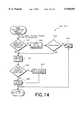
- FIG. 14is a flow chart showing a possible methodology that can be implemented in FIGS. 12 and 13 for adding a secondary object to a list associated with a primary object;
- FIG. 15is a flow chart showing a possible methodology that can be implemented in FIGS. 10 and 18 for prioritizing objects and determining a primary object from a list of objects;
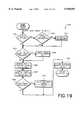
- FIG. 16is a flow chart showing a possible methodology that can be implemented in FIG. 13 for applying an overlap mode to local objects
- FIG. 17is a flow chart showing a possible methodology that can be implemented in FIGS. 9 and 16 for removing an object from the topology database of FIGS. 3A and 3B;
- FIG. 18is a flow chart showing a possible methodology that can be implemented in FIG. 17 for selecting a primary object from a list of secondary objects;
- FIG. 19is a flow chart showing a possible methodology that can be implemented in FIGS. 9 and 17 for deleting an object from the topology database of FIGS. 3A and 3B;
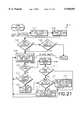
- FIG. 20is a flow chart showing a possible methodology that can be implemented in FIG. 9 for updating fields pertaining to an object in the topology database of FIGS. 3A and 3B;
- FIG. 21is a flow chart showing a possible methodology that can be implemented in FIG. 20 for changing station status
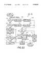
- FIG. 22is a flow chart showing a possible methodology that can be implemented in FIG. 20 for updating the topology database of FIGS. 3A and 3B;
- FIG. 23is a flow chart showing a possible methodology that can be implemented in FIG. 22 for forwarding events from the topology manager of FIGS. 3A and 3B to a remote station regarding local topology changes;
- FIG. 24is a block diagram illustrating a remote station list, global action list, and action wait list that are implemented within the replicator of FIG. 5;
- FIG. 25is a flow chart showing a possible methodology that can be implemented by the replicator in the management station of FIG. 3A;
- FIGS. 26A and 26Billustrate a flow chart showing a possible methodology that can be implemented in FIG. 25 for performing a synchronization action
- FIGS. 27A and 27Billustrate a flow chart showing a possible methodology that can be implemented in FIG. 25 for performing a status check action
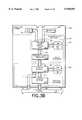
- FIG. 28is a flow chart showing a possible methodology that can be implemented in FIG. 25 for sequencing events received from remote systems.
- the discovery/layout software for implementing the distributed internet monitoring system of the present inventioncan be stored on any computer readable medium for use by or in connection with a computer related system or method.
- a computer readable mediumis an electronic, magnetic, optical or other physical device or means that can contain or store a computer program for use by or in connection with a computer related system or method.
- the novel discovery/layout softwarecan be stored and transported on a portable data storage device (e.g., a cassette), or as another example, can be stored in the memory of a computer for the purpose of driving the computer when called upon.
- FIG. 1shows a block diagram of an object-oriented station 100 (e.g., management station 100a of FIG. 3A or collection station 100b of FIG. 3B) that can be implemented with any suitable computer.
- a group of the stations 100is utilized in order to implement the distributed internet monitoring system.
- the computer-based station 100contains and is driven by discovery/layout software 101, which implements the distributed internet monitoring system of the present invention.
- the station 100contains any suitable processor 102.
- the processor 102communicates to other elements within the station 100 over a local interface 104, such as a bus or bus network.
- An input device 106for example, a keyboard or mouse, is used to input data from a user of the station 100, and an output device 108, for example, a display or printer, is used to output data to the user.
- a network interface 112is used to interface the station 100 to a network 118 in order to allow the station 100 to act as a node on a network 118.
- a memory 110 within the station 100contains the discovery/layout software 101, which implements the distributed internet monitoring system of the present invention.
- the memory 110is meant to be all-inclusive in that it includes both the volatile and nonvolatile memory elements, e.g., the random access memory, disk storage, cmos initialization memory, etc.
- the discovery/layout software 101communicates with any suitable operating system 122 and network software 124 to discover the nodes on the network 118 and to communicate with other computers executing the discovery/layout software.
- the network software 124serves as the intelligence, including validation, for the data communication protocols.
- the network softwareimplements TCP and UDP over IP, and the SNMP over the UDP. All of the foregoing protocols are well known in the art.
- the discovery/layout software 101implements object-oriented functionality.
- object-orientedmeans that most of the management system actions and processes that the user can invoke are oriented toward a class of devices rather than individually managed network nodes.
- the discovery/layout software 101 of the station 100 of FIG. 1is configured to discover the network topology, that is, network nodes and node interconnections existing on the network 118 in a particular region that is defined for the station 100, and to construct a network management map for the particular region comprising various submaps, any of which can be used for displaying the network topology on the output device 108.
- FIG. 2shows a network management map 200 which is generated by the discovery/layout software 101 from topology data discovered from the network 118.
- the discovery/layout software 101can drive any of the various submaps to the display 108 (FIG. 1) for viewing by the user.
- a root submap 202is defined at a root level.
- the root submap 202represents the highest logical level submap in the hierarchy and shows objects 203 acting as anchor points for different submap hierarchies.
- Each hierarchyis a separate management domain. This could be, for instance, a network, logical grouping of nodes, or some other domain.
- An internet submap 204is defined at an internet level and is generated by "exploding" an object 203 within the root submap 202. "Exploding" in the context of this document means that the user prompts the station 100 with the input device 106 to break down and provide more data pertaining to the object 203 at issue.
- the internet submap 204illustrates objects 203 in the form of networks and routers. Any one of a number of network submaps 206 can be exploded from the internet submap 204. Each network submap 206 shows objects 203 in the form of segments and connectors. Any one of a number of segment submaps 208 can be exploded from an object 203 within a network submap 206. Each segment submap 208 shows objects in the form of network nodes. Finally, any one of a number of node submaps 210 can be exploded from an object 203 within a segment submap 208. Each node submap 210 shows objects 203 in the form of interfaces within that node.
- the architecture of the management station 100ais shown in FIG. 3A.
- the discovery/layout software 101 of the management station 100acomprises a discovery mechanism 302 for discovering nodes and interconnections of the network 118 that are within the particular region defined for the management station 100a and a layout mechanism 304 for receiving topology data from the discovery mechanism 302 and for generating the network management map 200 (FIG. 2) for driving the display 108.
- one or more integrating applicationsmay communicate display and map information with the layout mechanism 304.
- the discovery mechanism 302has a network monitor 306 in communication with the network 118 as indicated by arrow 308, a topology manager 310 in communication with the network monitor 306 as indicated by arrow 312, and a topology database (dB) 314 in communication with the topology manager 310 as indicated by arrow 316.
- a network monitor 306in communication with the network 118 as indicated by arrow 308
- a topology manager 310in communication with the network monitor 306 as indicated by arrow 312
- dBtopology database
- the network monitor 306transmits and receives data packets to and from the network 118.
- the network monitor 306discovers and monitors network topology, as indicated by arrow 308.
- the network monitor 306When network topology changes on the network, the network monitor 306 generates events, or traps (SNMP vernacular), which include an object identifier and object change information.
- the network monitor 306can also receive events from other devices, such as a router, in the network 118.
- the network monitor 306interacts with the network 118 by way of the network software 124 (FIG. 1), which essentially comprises protocol stacks, corresponding to IP, TCP, UDP, and SNMP in the preferred embodiment, and which generally implements these protocols and performs validation functions.
- the network monitor 306populates the topology database 314 by way of the topology manager 310 and notifies the topology manager 310 of events (topology changes).
- the topology manager 310manages the topology database 314, as indicated by arrow 316.
- the topology manager 310prompts the network monitor 306 to update topology data related to particular events and receives topology updates, as indicated by arrow 312.
- the topology manager 310also responds to SNMP queries from remote replicators 303.
- the topology database 314stores topology data based upon objects, which are used to partition the network for logical reasons.
- Objectsinclude, for example but not limited to, a network, a segment, a computer, a router, a repeater, a bridge, etc.
- the topology data stored with respect to the objectsincludes, for example but not limited to, an interface or device address, an interface or device type, an interface or device manufacturer, and whether an interface or device supports the SNMP protocol.
- the management station 100aincludes a topology replicator 303, which enables the management station 100a to obtain other sets of topology data from other stations 100 (100a or 100b) in order to derive a global view of the network 118.
- the topology replicator 303is in communication with the network 118, as indicated by arrow 313, and is in communication with the topology manager 310, as is indicated by arrow 315.
- the topology replicator 303is responsible for tracking data from remote topology managers 310, which are situated within other stations 100 (FIG. 1), and merging that data into the local topology database 314.
- the replicator 303utilizes SNMP to communicate with remote stations 100.
- the replicator 303implements several novel algorithms for handling the data from remote stations 100, while the topology manager 310 implements several novel algorithms for merging the data into the topology database 314. These algorithms will be further described later in this document.
- the topology manager 310responds directly to the network 118 to queries from remote replicators 303, as indicated by arrow 311.
- the queriescorrespond to the SNMP/UDP/IP protocol in the preferred embodiment.
- the layout mechanism 304has a topology-to-map translator 318 in communication with the topology manager 310 as indicated by arrow 320, a graphical user interface (GUI) 322 in communication with the topology-to-map translator 318 as indicated by arrows 324, and a map database 326 in communication with the GUI 322 as indicated by arrow 328.
- GUIgraphical user interface
- the topology-to-map translator 318converts topology data from the topology database 314 to map data and constructs the various submaps 202-210 in the network management map 200 of FIG. 2.
- the topology-to-map translator 318can forward a request to the topology manager 310, as indicated by arrow 320, in order to obtain topology data regarding particular objects.
- the topology manager 310advises the topology-to-map translator 318 of when topology data has changed based upon an event so that the translator 318 can make any appropriate changes in the submaps 202-210.
- the GUI 322manages the map database 326, as indicated by the arrow 328, and manages the display 108 and input device 106, as indicated by the arrow 330b.
- the GUI 322receives map updates from the translator 318, as indicated by arrow 324, and submits user-triggered events to the translator 318, as indicated by arrow 324.
- a user-triggered eventincludes a prompt 330a from a user to explode an object, as described relative to FIG. 2.
- the discovery/layout software 101 of the collection station 100bis illustrated in FIG. 3B.
- the architecture of the discovery/layout software of the collection station 100bis very similar to that of the management station 100a, as described with reference to FIG. 3A hereinbefore.
- FIGS. 3A and 3Blike reference numerals designate corresponding components, and furthermore, in regard to the collection station 100b of FIG. 3B, the discussion previously in regard to like elements is incorporated herein by reference.
- the collection station 100bunlike the management station 100a, does not utilize a topology replicator 303 to enable the collection station 100b to obtain other sets of topology data from other stations 100 in order to derive a global view of the network 118.
- the topology manager 310uses the network to respond to queries from the replicator 303 (FIG. 3A), as indicated by reference arrow 311 in FIG. 3B. In the preferred embodiment, queries conform to the SNMP/UDP/IP protocol.
- a distributed internet monitoring system 400 in accordance with the present inventionwill now be described with reference to FIG. 4.
- two or more stations 100assist each other in monitoring the network 118.
- a management station 100acommunicates to at least one other station 100, such as a collection station 100b or a management station 100a.
- a management station 100ais shown in communication with a collection station 100b.
- the discovery mechanism 302 associated with each station 100a, 100bis assigned to monitor a predefined respective region of the network 118. Further, the discovery mechanism 302 of the collection station 100b shares its local topology data with the discovery mechanism 302 of the management station 100a so that the management station 100a can generate and display a global view of the network 118.
- the discovery mechanism 302 of the collection station 100bcommunicates its topology data to a replicator 303 in the discovery mechanism 302 of the management station 100a.
- the aforementioned communicationcan occur over the network 118 or over some other communication link, including a dedicated connection.
- the communication indicated by arrow 402occurs via the SNMP/UDP/IP protocols over the network 118.
- topology objectsare the internal representation of real world objects, and the term is used to refer both to the organization of the data as well as to the internal structures used to track that data. For example, for a given computer (node) in the real world, the system 400 will track a body of data about that node. That data is stored in a form that models that node in the topology database 314. Additionally, the topology manager 310 and the applications that deal with it will read that data into an internal structure that represents that node's data, and that internal structure is referred to as a "topology node object” or just a "node.”
- each topology manager 310tracks the following types of objects: (a) a node object that represents the computers and connective devices in the network 118; (b) an interface object that represents the logical connections of the node to various networks; every interface must be associated with a node, and a node may have zero or more interfaces; (c) a segment object that represents a physical cable to which nodes are attached via interfaces; a segment conceptually contains those nodes which have interfaces connected to the segment; (d) a network object that represents a logical IP network; (e) the network object conceptually contains several segments and the nodes that are connected to those segments; (f) a global internet object that contains global information and conceptually contains all other objects; and (g) a station object that represents a remote node that is acting as a host for the collection station software; a station object conceptually contains all the objects that are reported by that collection station's topology manager 310.
- Each of the above objectscontains in it a generic object structure that is common to all the objects.
- the generic object structureis used when a method or algorithm can be applied independently of the type of object.
- the generic objectis a base class for the more specific objects.
- Each type of objecthas a unique type of "name” field that is used to identify it.
- namesFor example, networks have an "IP Network Name” that is based on the IP subnet address and subnet mask of the network. Segments have an “IP Segment Name” that is composed of the name of the network that contains the segment, and the word “segment” with a unique number after it.
- Nodeshave an "IP Hostname” that is based on the official IP hostname of the node, while each interface has an IP address.
- Each objecthas multiple types of identifiers (IDs).
- IDsidentifiers
- each individual objecthas a "universal unique identifier" (UUID).
- UUIDis basically a string that is guaranteed to be unique across multiple stations 100.
- each objecthas associated with it a local identifier called the "local object ID”.
- This identifieris an integer for use within a local station 100.
- the local object ID on the remote station 100is copied into a field in the object called the "remote object ID" at the management station 100a, as indicated by reference arrow 509.
- the remote object IDis tracked by the replicator 303 of the management station 100a and used to communicate with the remote station 100.
- the UUID for each objectremains the same in both the remote station 100 and the management station 100a.
- the topology manager 310supports the concept of both "removed” and "deleted” objects. Objects which are deleted have all data removed from the topology database 314 and are no longer tracked by the topology manager 310. Objects which are marked as removed objects are objects that are pending deletion once all symbols representing the object have been removed from the GUI 322 (FIGS. 3A, 3B) by the topology translator 318 (FIGS. 3A, 3B). Removed objects are tracked by the topology manager 310, but are not generally involved in some of the other relationships tracked by the topology manager 310.
- a typical boundary overlapcan occur at the WAN-link 602 between two sites 604, 606, as shown in FIG. 6.
- two stations 100are each monitoring a corresponding local site, but are also monitoring the WAN-link 602 and the gateway 608, 610 on the other side of the link 602.
- the userwill configure the stations 100 to have some overlap, particularly of important nodes like gateways and routers.
- an approachis taken in which a copy of the data for each object is tracked.
- one version of the objectis chosen as the "primary" version of the object.
- the primary version of the objectis used to determine the object's status and other presentation attributes for the user.
- the network monitor 306 or the topology replicator 303deal with objects, they deal with a particular version for a particular station 100 (the local station 100 in the case of the network monitor 306; a particular remote station 100 in the case of the topology replicator 303).
- the network monitor 306 of one station 100discovers the topology data 702, which includes the gateways 1 and 2 and network 1, and further, the discovery mechanism 302 of another station 100 discovers topology data 704, which includes the gateways 1 and 2 and a network 2.
- the topology translator 318deals only with the primary versions of objects, presenting a merged view 706 to the users.
- the merged view 706includes primary versions of gateways 1 and 2 and networks 1 and 2.
- the topology manager 310tracks the multiple versions of objects in two different ways, as will be described with reference to FIGS. 8A and 8B.
- the different versions of an objecthave the same object ID assigned to them.
- the different versionsare distinguished by which station 100 is reporting the particular version. Other ID's are assigned when an object is first given to the topology manager 310 to insert into the topology database 314.
- each type of objecthas a unique type of name (e.g. node objects have an IP Hostname) that should uniquely identify an object of a given type.
- IP Hostnamee.g. 10.1.1.1
- Two node objects with the same IP Hostnameshould really be two versions of the same object. Note that this is a description of the rules currently enforced in the code.
- local object ID'sare assigned based on the name field for the object. If no name field exists, or if there is no existing object with the same name, a new local object ID is created. If an object exists with the same name, the same object ID is returned to be assigned to the new object.
- this algorithmshows an object ID as being an integer value that is stored in nonvolatile memory and initialized to zero. Any format of object ID and algorithm for generating a unique one can be used without altering the basis of the design.
- the system 400In addition to a local object ID and the object ID of the station reporting the object version, the system 400 also tracks the object ID of the object version as reported by the remote station 100. This is used to identify the object for future updates by the topology replicator 303. In the case of objects monitored locally by the network monitor 306, the local object ID and the remote object ID are the same.
- FIG. 9illustrates a preferred methodology that is employed by the topology manager 310 (FIGS. 3A and 3B).
- the topology manager 310handles requests for topology information and for database updates from the network monitor 306, replicator 303, and the topology-to-map translator 318.
- each flow chart blockrepresents a subroutine, block, or module of executable instructions or code.
- Block 901initializes the communications protocols.
- the codesets up to use the SNMP and UDP/IP. These protocols and their initialization are well known in the art. Block 901 transfers to block 902.
- Block 902reads in all data from the topology database 314 into memory and builds initial lists. In the preferred embodiment, a list of topology objects is built in memory for each object type. Block 902 transfers to block 903.
- the topology manager 310waits for an incoming request for topology data or for database updates. After a request is received, block 903 transfers to block 904.
- the topology manager 310determines whether the request is for topology data or for an object update. If the request is for topology data, then block 904 transfers to block 905. Otherwise, block 904 transfers to block 907.
- block 905looks up the relevant objects in the topology database 314 and obtains the desired data. Block 905 then transfers to block 906, which drives the topology data to the component that requested the information. Finally, block 906 transfers back to block 903, where the topology manager 310 awaits another request.
- block 907makes a determination as to whether the object is marked as a new object. If so, then block 907 transfers to block 908. If not, then block 907 transfers to block 910.
- block 908adds the object to the topology database 314.
- the process of block 908will be further described hereafter with reference to FIG. 10.
- Block 908then transfers to block 909, where an acknowledgement that the object has been added is sent to the source of the request. Further, the block 909 transfers to block 903, where the topology manager 310 awaits another request.
- block 910makes an inquiry as to whether the object is to be removed. If so, then block 910 transfers to block 911. Otherwise, block 910 transfers to block 913.
- block 911marks the object "removed" in the topology database 314, as further described in FIG. 17.
- Block 911transfers to block 912, where an indication that the block has been removed is sent to the source of the request.
- block 912transfers to block 903, where the topology manager 310 awaits another request.
- block 913makes an inquiry as to whether the object has been marked for deletion. If so, then block 913 transfers to block 914. Otherwise, block 913 transfers to block 916.
- Block 914the object is deleted from the topology database 314.
- the process of block 914will be further described hereafter with reference to FIG. 19.
- Block 914transfers to block 915.
- an indication that the object has been deletedis sent to the source of the request, and then block 915 transfers to block 903, where the topology manager 310 awaits another request.
- block 916a determination is made as to whether the object is marked for an update of its fields. If so, then block 916 transfers to block 917. If not, then block 916 transfers back to block 903, where the topology manager 310 awaits another request.
- block 917updates the object fields in the topology database 314. This process will be further described with reference to FIG. 20 hereafter.
- block 917transfers to block 918, where an indication that an update has occurred is sent to the source of the request.
- block 918transfers to block 903, where the topology manager 310 awaits another request.
- FIG. 10shows the code for adding an object. This process is implemented in block 908 of FIG. 9.
- the add object subroutine of FIG. 10verifies the integrity of the object, inserts the object into the topology database 314, and determines if there is an overlap with another object reported from another station 100.
- the fields of the objectare initialized.
- the fields that are initializeddepends in large part upon the type of object. If an object is to be a primary object, then secondary fields associated with it are emptied. Counts of contained objects are initialized to zero. Lists of contained objects are initialized. After this initialization process, block 1001 transfers to block 1002.
- Block 1002object identifiers are verified. This process is more fully described with reference to FIG. 11. This is one of the places where an overlap can be detected by examining object names. As part of this process, the object is checked for a UUID and a local ID. A local ID may be assigned, if none exists. Block 1002 transfers to block 1003.
- Block 1003makes a determination as to whether the object identifiers have been verified based upon the results of block 1002. In other words, block 1003 determines whether the object has both a UUID and a local ID. If not, then block 1003 transfers to block 1004, which generates an error signal and passes the program flow to block 909 of FIG. 9. If verified, then block 1003 transfers to block 1005.
- Block 1005transfers to block 1006.
- a station listis searched to ensure that each object has a station ID, which identifies the station monitoring that object. If a station 100 with a station ID is found in the list, then block 1012 adds the object to the stations list of objects, and then block 1012 transfers to block 1013. If a station ID is not found for an object, then block 1010 makes the determination as to whether the object has been marked for removal. If not, then an error message is generated by block 1011. If so, then block 1010 transfers to block 1013.
- Block 1013the topology database 314 (FIG. 3) is updated. This process will be more fully described with reference to FIG. 22. Block 1013 transfers to block 1014.
- an inquiryis made as to whether the object should be made the primary.
- the preferred processis set forth in FIG. 15 and will be described hereafter. If the object should not be the primary, then block 1015 transfers to block 1018, the subroutine 908 concludes, and the subroutine 908 transfers to FIG. 9 in order to execute block 909. If the object should be the primary, then block 1015 transfers to block 1016, which makes the object the primary. This process will be further described with reference to FIG. 13 later in this document. Afterwards, block 1016 transfers to block 1019, which concludes the subroutine 908, and then the subroutine 908 transfers to FIG. 9 for execution of block 909.
- FIG. 11shows the code for verifying object identifiers. This process is implemented at block 1002 in FIG. 10. This is one of the places in the program where an overlap can be detected by examining object names. In general, if an object does not have a UUID, then an error is returned. Moreover, if an object does not have a local object ID, then a local object ID is obtained.
- an inquiryis made as to whether the local object ID has been set for the object. If not, then block 1103 transfers to block 1104. At block 1104, a determination is made as to whether the object has the same name and type as an existing object in the local object ID set. If not, then block 1104 transfers to block 1105, which allocates a new local object ID for the object. If there is a match, then block 1104 transfers to block 1106, which sets the local object ID to match the existing object ID.
- block 1107is executed.
- a determinationis made as to whether the object has a remote object ID. If not, then block 1107 transfers to block 1108, where a determination is made as to whether the object is locally monitored. If yes, then block 1108 transfers to block 1109, which sets the remote object ID to the local object ID.
- the subroutine 1002concludes and returns to execute block 1003 in FIG. 10 when the object has a remote object ID, when the object is not to be locally monitored, and after execution of block 1109.
- FIG. 12shows the code for checking for existing objects. This process is implemented at block 1005 in FIG. 10. Here, error detection is performed and objects that match are placed on an overlap list.
- block 1201searches for the object in a topology database using the UUID. Block 1201 transfers to block 1202.
- block 1203a determination is made as to whether the object has been marked for removal. If the object is not marked for removal, then there is no reason to reinsert it, and an error message is generated by block 1204. If the object is marked for removal, then the user was trying to delete it from the maps. Accordingly, block 1205 deletes the removed version. This process is further described with reference to FIG. 19. Afterwards, block 1205 transfers to block 1206.
- Block 1206transfers to block 1207.
- block 1207a determination is made as to whether the object has been found in the local ID set. If not, then block 1207 transfers to block 1212. If so, then block 1207 transfers to block 1208, where an inquiry is made as to whether the existing object is the primary. If so, then block 1208 transfers to block 1209, which adds the new object as the secondary object (process described with reference to FIG. 14), and the result is returned by block 1210. If the existing object is not the primary, then block 1208 transfers to block 1211, which makes the new object the primary. This process is further described with reference to FIG. 13.
- block 1212a determination is made as to whether the new object is marked primary. If so, then block 1212 transfers to block 1213, which inserts the object in the global object lists, and then block 1213 transfers to block 1214. If the new object is not marked primary at block 1212, then block 1212 transfers to block 1214.
- the subroutine 1005concludes and returns to execute block 1006 in FIG. 10.
- FIG. 13shows the code for making an object a primary. This process is implemented at blocks 1016 and 1807 of FIGS. 10 and 18, respectively.
- an objectis sought to be made the primary of an object list.
- the objectmay already exist in that list of secondaries or it may be a newly reported object.
- the subroutine in FIG. 13moves the secondaries from the list over to the new object, and then the old primary is added into the secondaries for the new object.
- block 1301a determination is made as to whether there is an old primary version of the object. If not, then block 1301 transfers to block 1314. If so, then block 1301 transfers to block 1302.
- an inquiryis made as to whether the old primary has a list of secondaries. If not, then block 1302 transfers to block 1311. If so, then block 1302 transfers to block 1303.
- block 1303When there is a list of secondaries, block 1303 sets a variable OBJ to the first secondary in the list. Block 1303 transfers to block 1304.
- a loopcommences at block 1304 to examine each secondary in the list.
- Block 1304makes an inquiry as to whether the object is at the end of the list. If not, then block 1304 transfers to block 1305, which sets a variable NEXTOBJ to the next secondary in the list.
- Block 1305transfers to block 1306.
- the primary pointer of the secondary objectis set to the new primary.
- Block 1306transfers to block 1307.
- a determinationis made as to whether the current secondary object is the new primary version. If so, then block 1307 transfers to block 1308, which removes the object from the list of secondaries. If the object is not the new primary version, then block 1307 transfers to block 1309.
- the variable OBJis set to the variable NEXTOBJ, and block 1309 transfers back to block 1304.
- block 1304transfers to block 1310.
- the list of secondariesis moved to the new primary object.
- Block 1310transfers to block 1311.
- block 1311the old primary object is added as a secondary object. This process is further delineated at FIG. 14. Afterwards, block 1311 transfers to block 1312.
- Block 1312removes the old primary object from the global object list. Block 13112 transfers to block 1313.
- an overlap modeis applied to the old primary object. This process is further described with reference to FIG. 16.
- the secondary objectis set to one of three modes. There is an “allow it” mode, which means nothing is done with the old primary object; an “unmanaged” mode, which means keep the old primary object around but make it unmanaged and do not do anything with it; and a “delete” mode, which means get rid of the old primary object completely. Networks and segments are not deleted and are kept around as unmanaged because they help keep the topology infrastructure. Block 1313 transfers to block 1314.
- block 1314a determination is made as to whether the new primary object is marked as a secondary object. If so, then block 1314 transfers to block 1315, which marks the new version as the primary object. If not, then block 1314 transfers to block 1316.
- Block 1316the new primary object is added to the global lists. Block 1316 transfers to block 1317, which concludes the routine 1016, 1807, and the subroutine 1016, 1807 returns to either FIG. 10 or FIG. 18.
- FIG. 14shows the code for adding a secondary object to a list associated with a primary object. This process is implemented at blocks 1209 and 1311 in FIGS. 12 and 13, respectively. Basically, one object matches another, and the code puts the second on a list of objects that match. For optimization, a list is not created if there is nothing to put in it.
- block 401a determination is made as to whether a list of secondaries exist for the primary object. If not, then block 1401 transfers to block 1402. If so, then block 1401 transfers to block 1405.
- block 1402When there is not a list of secondaries for the primary object, block 1402 creates a list of secondaries and transfers to block 1403 to ensure that the process was successful. If not, then an error message is generated by block 1404 and the subroutine 1209, 1311 terminates by returning to either FIG. 12 or FIG. 13. If successful, then block 1403 transfers to block 1405.
- Block 1405adds the new object version to the list of secondaries. Block 1405 transfers to block 1406.
- an inquiryis made as to whether the new object version is marked as a secondary. If not, then block 1406 transfers to block 1407, which marks the new version as a secondary, and then block 1407 transfers to block 1408. If the new version is marked as a secondary, then block 1406 transfers to block 1408.
- Block 1408concludes the subroutine 1209, 1311 by returning a success message, and then the subroutine 1209, 1311 returns to either FIG. 12 or FIG. 13, depending upon its initiation origin.
- FIG. 15shows the code for prioritizing objects and determining a primary object from a list of objects. This process is implemented in blocks 1015 and 1809 of FIGS. 10 and 18, respectively.
- the priority schemeis as follows. Objects that are marked removed are not selected as the primary. Objects from stations 100 that have been in communication in the past are given priority over those objects from those stations 100 that have not been in communication. Managed objects are given priority over unmanaged objects. Finally, objects from remote stations 100 are given priority over objects from local stations 100.
- block 1501a determination is made as to whether any of the secondary objects have been marked for removal. If so, then block 1501 transfers to block 1502, which designates the current primary as the primary, and then block 1502 transfers back to either FIG. 10 or FIG. 18, depending upon which block of code initiated the process of FIG. 15.
- block 1501transfers to block 1503.
- block 1503a determination is made as to whether the primary object is marked as removed. If so, then block 1503 transfers to block 1504, which identifies the secondary object as the primary object. Block 1504 then transfers back to either FIG. 10 or FIG. 18. If, to the contrary, the primary object is not marked removed, then block 1503 transfers to block 1505.
- the algorithmis structured so that there is greater trust for a station 100 that the current station 100 is communicating with than one that the current station 100 has not been communicating with.
- the secondary objectis checked first so that the primary is kept if both of them are down or if both of them are unmanaged. If the station 100 that is monitoring the secondary object is down or the secondary object is unmanaged, then block 1505 transfers to block 1506.
- Block 1506chooses the primary object as the primary, and the subroutine 1015, 1809 concludes. In the alternative, block 1505 transfers to block 1507.
- block 1507an inquiry is made as to whether the station 100 that is monitoring the primary object is down or whether the primary object is unmanaged. If either of the foregoing inquiries are in the affirmative, then block 1507 transfers to block 1508, which chooses the secondary object as the new primary. If either of the foregoing inquiries are in the negative, then block 1507 transfers to block 1509.
- block 1509a determination is made as to whether the primary object is preferred by the user. This priority is input by the user and is kept track of with a flag on the object. If the primary object is preferred by the user, then block 1509 transfers to block 1510, which chooses the primary object as the new primary. If not, then block 1509 transfers to block 1511.
- Block 1511makes an inquiry as to whether the secondary object is preferred by the user. If so, then block 1511 transfers to lock 1512. Block 1512 chooses the secondary object as the new primary. If at block 1511 it is determined that the secondary object is not preferred by the user, then block 1511 transfers to block 1513.
- block 1513a determination is made as to whether the secondary object is unmanaged and the primary object is managed. If this is the case, then block 1513 transfers to block 1514, which chooses the primary object as the new primary. If this is not the case, then block 1513 transfers to block 1515.
- block 1515an inquiry is made as to whether the primary object is unmanaged and the secondary object is managed. If this is the case, then block 1515 transfers to block 1516, which chooses the secondary object as the new primary. If this is not the case, then block 1515 transfers to block 1517.
- Block 1517makes the determination as to whether the secondary object is contained in another object that is a primary object. As an example, if a particular node is in a segment or network, then the node should get its data from the same station 100 that is utilized for getting the data for the segment or network containing that node. If the answer to the inquiry is in the affirmative, then block 1517 transfers to block 1518, which chooses the secondary object as the new primary. If the answer to the inquiry is in the negative, then block 1517 transfers to block 1519.
- a remote object versionis given preference over a local object version. This is by design choice as it is assumed that a remote station 100 is closer to the remote object(s) being monitored.
- FIG. 16shows the code for applying the overlap mode for local objects.
- This processis implemented at block 1313 in FIG. 13.
- this processis a special feature to help users who are transitioning from monitoring everything centrally to monitoring things remotely.
- this processis only applied to local objects, that is, objects monitored locally by the local discovery process.
- the processis utilized when a locally monitored object is a secondary for a primary from another remote station 100.
- block 1601an inquiry is made as to whether the object is marked as a primary or removed. If so, then block 1601 transfers to block 1602, which returns to FIG. 13. Otherwise, when the object is not marked as a primary or removed, then block 1601 transfers to block 1603.
- block 1603a determination is made as to whether the object is locally monitored. If not, then block 1603 transfers to block 1604, which concludes the subroutine 1313 and transfers back to the code in FIG. 13. In the alternative, when the object is monitored locally, block 1603 transfers to block 1605.
- Block 1605makes a determination as to whether the overlap mode is set to unmanaged. If so, then block 1605 transfers to block 1606. Block 1606 specifies the object as unmanaged and transfers to block 1607, which concludes the subroutine 1313 and transfers to the code of FIG. 13. Otherwise, when the overlap mode is not set to unmanaged for this object, block 1605 transfers to block 1608.
- Block 1608makes an inquiry as to whether the overlap mode is set to "delete.” If not, then block 1608 transfers to block 1609, which concludes the subroutine 1313 and transfers the code of FIG. 13. Alternatively, when the overlap mode is set to delete, then block 1608 transfers to block 1610.
- Block 1610determines whether the object is a network or segment. If so, then block 1610 transfers to block 1611, which defines the object as unmanaged and which transfers back to the code of FIG. 13. In the event that the object is not a network or segment, block 1610 transfers to block 1613.
- Block 1613determines whether the object is a node. If so, block 1613 transfers to block 1614.
- Block 1614determines whether the node is a connector. When the node is a connector, block 1614 transfers to block 1615, which defines the node and the interfaces therein as unmanaged and concludes operation of the subroutine 1313. When the node is not a connector, block 1614 transfers to block 1617, which removes the node. This process is further described with reference to FIG. 17.
- block 1613transfers to block 1616, which terminates the subroutine 1313 and returns to the code of FIG. 13.
- FIG. 17shows the code for marking an object "removed" in the topology database 314. This process is implemented at blocks 914 and 1617 of FIGS. 9 and 16, respectively.
- Block 1701marks the object as one to be removed by setting an appropriate internal flag. Block 1701 transfers to block 1702.
- block 1702a determination is made as to whether the object is a primary object. If so, then block 1702 transfers to block 1703, which chooses a new primary object. The preferred code for implementing this step is set forth in FIG. 18. Block 1703 transfers to block 1704. Furthermore, when it is determined that the object is not the primary object at block 1702, block 1702 transfers to block 1704.
- Block 1704makes a determination as to whether the object is marked as a secondary object. If so, block 1704 transfers to block 1705, which sets an internal flag to indicate that the object should be deleted. Then, block 1705 transfers to block 1706. In the event that it is determined at block 1704 that the object is not marked as a secondary, then block 1704 transfers to block 1706.
- Block 1706updates the topology database 314. This process will be further described with reference to FIG. 22. Afterwards, block 1706 transfers to block 1707.
- block 1707a determination is made as to whether the object has been marked for deletion. If so, block 1707 transfers to block 1708, which deletes the object. The preferred methodology for this deletion is set forth in FIG. 19. Block 1708 transfers to block 1709. When it is determined that the object is not marked for deletion at block 1707, block 1707 transfers to block 1709.
- Block 1709concludes the subroutine 914, 1617 by returning a success flag pertaining to the object and returning to the code of either FIG. 9 or FIG. 16, depending upon which block of code initiated the subroutine.
- FIG. 18shows the code for selecting a primary object from the list of secondary objects. This process is implemented at block 1703 in FIG. 17 and at block 914 in FIG. 9.
- Block 1801a determination is made as to whether there are any secondary objects given the current primary object. If not, then block 1801 transfers to block 1802, which returns the current primary object. If there are secondary objects, then block 1801 transfers to block 1803, which sets the variable "saved -- obj" to the primary object. Block 1803 transfers to block 1804.
- Block 1804determines whether there are any more secondary objects. If so, then block 1804 transfers to block 1809. Otherwise, block 1804 transfers to block 1805.
- block 1809determines whether any of the secondary objects should be the primary object. In order to make this decision, the code in FIG. 15 is again executed. If it is determined that the secondary object should not be the primary, then block 1809 transfers to block 1804. Otherwise, block 1809 transfers to block 1810, which saves the secondary object as the primary (sets the variable "saved -- obj") and transfers to block 1804.
- block 1804transfers to block 1805.
- Block 1805an inquiry is made as to whether the primary object has changed. If it has not changed, then block 1805 transfers to block 1806, which transfers back to block 1704 in FIG. 18. When the primary object has changed, then block 1805 transfers to block 1807, which makes the saved object the new primary object. This process is further delineated at FIG. 13. Block 1807 transfers to block 1808, which concludes the subroutine 1703 and transfers to block 1704 in FIG. 17.
- FIG. 19shows the code for deleting an object from the topology database 314. This process is implemented at block 1708 in FIG. 17.
- Block 1901a determination is made as to whether the object is a primary object. If so, then block 1901 transfers to block 1902. Block 1902 determines whether the primary object has any secondary objects. If not, then block 1902 transfers to block 1904. If so, then block 1902 transfers to block 1903, which deletes all the secondary objects and then transfers to block 1904. When it is determined that the object is not a primary at block 1901, then block 1901 transfers to block 1904.
- Block 1904determines whether the object is marked for removal. If not, then block 1904 transfers to block 1905, which removes the object in accordance with the methodology set forth in FIG. 17 and transfers to block 1906. When it is determined that the object has been marked for removal at block 1904, then block 1904 transfers to block 1906.
- Block 1906removes the object from the global object list. Block 1906 transfers to block 1907.
- Block 1907removes the object from the stations object list. Block 1907 transfers to block 1908.
- Block 1908determines whether the object is marked as a secondary object. If so, then block 1908 transfers to block 1909 which removes the secondary object in accordance with the methodology set forth in FIG. 17 and transfers to block 1910. When it is determined that the object is not marked as a secondary at block 1908, then block 1908 transfers to block 1910.
- Block 1910updates the topology database 314. This process will be described in further detail with reference to FIG. 22. Afterwards, the subroutine 1708 transfers either to block 1709 in FIG. 17 or to block 914 in FIG. 9.
- FIG. 20shows the code for updating fields pertaining to an object in the topology database 314. This process is implemented at block 915 in FIG. 9. Subroutine 915 is implemented when there has been a change to a field of an object. As examples, the fields change when the IP address of the object has changed, when the status of the object has changed, or when an internal flag has changed.
- Block 2001searches for the existing object by using the UUID. Block 2001 transfers to block 2002.
- Block 2004updates the generic object fields, for example, the object status or the internal flags. Block 2004 transfers to block 2005.
- Block 2005updates the specific fields pertaining to the object type. For example, in the case of a node object, a host name is updated. As another example, for an interface, the IP mask may change. Block 2005 transfers to block 2006.
- Block 2006a determination is made as to whether the object is a primary object. If not, then block 2006 transfers to block 2007.
- Block 2007determines whether the object is to be changed to a primary object. If so, then block 2007 transfers to block 2008, which makes the object a primary object in accordance with the methodology set forth in FIG. 13 and transfers to block 2009. To the contrary, if the object is not to be changed to the primary object, then block 2007 transfers to block 2015. Moreover, if at block 2006, it is determined that the object is the primary object, then block 2006 transfers to block 2009.
- Block 2009determines whether the status of the object has changed. If so, then the status field is modified. In this regard, block 2009 transfers to block 2010.
- block 2010,an inquiry is made as to whether the object is a station 100. If so, then block 2011 changes the station status in accordance with the methodology set forth in FIG. 21 and transfers to block 2013. If the object is not a station, then block 2010 transfers to block 2012, which propagates the status to objects containing the present object and then transfers to block 2013. As an example, if the status of a node has changed, then the status of segments containing the node may also have changed and the status fields of any such segments are modified. If, at block 2009, it is determined that the status of the object has not changed, then block 2009 transfers to block 2013.
- Block 2013makes a determination as to whether any change has affected any of the topology relationships. This determination depends upon the fields that are updated. For example, if an interface is getting moved from one segment to another segment because the system has detected that the node is actually moved, this information must be updated. When the change does affect the topology relationships, then block 2013 transfers to block 2014. At block 2014, the lists are updated as appropriate. Afterwards, block 2014 transfers to block 2015. At block 2013, if it is determined that the change does not affect the topology relationships, then block 2013 transfers to block 2015.
- Block 2015updates the topology database 314 in accordance with the methodology set forth in FIG. 22, as will be described hereafter. Upon completion, it transfers to block 2016, which returns to the code in FIG. 9.
- FIG. 21shows the code for changing a station's status.
- a status fieldis manipulated in the station object. This process is performed at block 2011 in FIG. 20.
- the subroutineis called upon when the replicator 303 has detected some change in the status of a remote status 100.
- the replicator 303periodically checks with other stations 100 in order to detect whether the present station 100 can communicate with and retrieve information from the remote stations 100.
- Another example when the status of a station 100 can changeis when the user specifies a station 100 as unmanaged. In this scenario, the user is indicating that the user does not wish to receive information any more from the specified station 100.
- Block 2101the old status of the station 100 is changed to the current status of the station 100.
- Block 2101transfers to block 2102.
- Block 2102sets the status of the station 100 to the new status. Block 2102 transfers to block 2103.
- Block 2103determines whether the new status is critical or unmanaged. A station 100 is "critical" when the current station 100 attempted to communicate with the remote station 100 several times and did not get any response. If the answer to the inquiry is in the negative, then block 2103 transfers to block 2104. Alternatively, block 2103 transfers to block 2105.
- block 2104a determination is made as to whether the old status is critical or unmanaged. If not, then block 2104 returns to block 2012 of FIG. 20. Otherwise, block 2104 transfers to block 2105.
- a loopcommences at block 2105 in order to change the status of each object that is monitored by the station 100 whose status has changed.
- Each iteration of the loopchecks and updates, if necessary, the status of each object pertaining to the station 100 at issue.
- An objectis retrieved at block 2105, if any remain, and block 2105 transfers to block 2106.
- Block 2106determines if the object is a primary object. If so, then block 2106 transfers to block 2109 which chooses a new primary in accordance with the methodology set forth in FIG. 18. Further, block 2109 transfers to block 2110, which makes a determination as to whether the object is still the primary object. If not, then block 2110 transfers back to block 2105. If so, then block 2110 transfers to block 2111, which determines whether the new status is critical or unmanaged. If not, then block 2111 transfers to block 2112 which sets the object status based on the remote station status or status propagation. If the new status is critical or unmanaged, then block 2111 transfers to block 2113, which sets the status of the object to unknown if the object is not unmanaged.
- Block 2106if it is determined that the object is not a primary object, then block 2106 transfers to block 2107.
- Block 2107determines whether the object should be the primary object based upon the methodology set forth in FIG. 15. If not, then block 2107 transfers back to block 2105 for analysis of the next object. If the object should be the primary, then block 2107 transfers to block 2108, which makes the object the primary object in accordance with the methodology set forth in FIG. 13. Moreover, block 2108 transfers to block 2111, the functionality of which was previously described.
- block 2105transfers to block 2012 in FIG. 20.
- FIG. 22shows code for updating the topology database 314. This process is performed at block 1013 of FIG. 10, at block 1706 of FIG. 17, at block 1910 of FIG. 19, and at block 2015 of FIG. 20.
- Block 2201an inquiry is made as to whether the object is new. If so, then block 2201 transfers to block 2202, which inserts the generic fields pertaining to the object. Block 2202 transfers to block 2203, which inserts the specific fields pertaining to the object entry. Block 2203 transfers to block 2211. At block 2201, if it is determined that the object is not new, then block 2201 transfers to block 2204.
- Block 2204a determination is made as to whether the operation to be performed is a delete operation. If so, then block 2204 transfers to block 2205, which deletes the generic object entry. Block 2205 transfers to block 2206, which deletes the object specific entry. Block 2206 transfers to block 2211. At block 2204, if it is determined that the operation is not a delete operation, then block 2204 transfers to block 2207.
- Block 2207updates the generic object entry. Block 2207 transfers to block 2208.
- Block 2208transfers to block 2209.
- Block 2211determines whether the object is a node. If not, then block 2211 transfers to block 2214, which generates events pertaining to the operation at issue. This process will be further described with reference to FIG. 23. After block 2214 is executed, block 2214 transfers to block 2215, which concludes the subroutine 2015 and transfers to block 2016 in FIG. 20. If at block 2211 it is determined that the object is a node, then block 2211 transfers to block 2212, where a loop is commenced to update the interfaces within the node. An interface is retrieved and then block 2212 transfers to block 2213. Block 2213 updates the topology database 314 relative to the interface pursuant to the methodology set forth in FIG. 22. Block 2213 transfers back to block 2212 and processes another interface, if any remain. After all interfaces have been processed, block 2212 transfers to block 2214.
- Block 2214generates events, if necessary, regarding topology updates. This process will be described with reference to FIG. 23. Afterwards, block 2214 transfers to block 2215, which returns the results and returns to FIG. 20.
- FIG. 23illustrates the code that is employed at block 2214 in FIG. 22.
- the subroutine 2214 as shown in FIG. 23notifies replicators 303 to update any remote topology database situated at any remote station 100.
- Block 2301the field change event is initialized with a sequence number. Block 2301 transfers to block 2302.
- block 2302a determination is made as to whether the object is to be deleted or added. If so, then block 2302 transfers to block 2307. If not, then block 2302 transfers to block 2303.
- Block 2303commences a loop where each field of the object is examined. Block 2303 picks the next field of the object to update and transfers to block 2304. At block 2304, a determination is made as to whether the field was found. If not, then block 2304 transfers to block 2307. If so, then block 2304 transfers to block 2305.
- Block 2305makes an inquiry as to whether the field is a management information base (MIB) object, which standard is well known in the art.
- MIBmanagement information base
- the MIBis specified by the SNMP standard and is basically, a conceptual database for exposing information through the SNMP protocol. If not, then block 2305 transfers to block 2303. If so, then block 2305 transfers to block 2306, which adds the field to the field change event and transfers back to block 2303.
- MIBmanagement information base
- block 2307an inquiry is made as to whether any fields have been added to the field change event. If not, then block 2307 transfers to block 2310, which cancels the field change event. If so, then block 2307 transfers to block 2308.
- Block 2308sends the field change event to any remote station 100 so that the remote databases 314 can be updated. Block 2308 then transfers to block 2309, which increments the sequence number pertaining to the field change event to indicate that the field change event has been initiated. Finally, the subroutine 2214 terminates and returns control to block 2215 in FIG. 22.
- the topology replicator 303maintains a remote station list 2402, a global action list 2404, and an action wait list 2406, as is illustrated in FIG. 24.
- the remote station list 2402is a list of all remote station objects managed by the local station 100 having the replicator 303.
- a remote station objectrepresents a remote station 100 with which the replicator 303 communicates and from which remote topology data is received and merged with local topology data to form a distributed topology.
- the topology manager 310maintains a set of remote station objects (RSOs) in the topology database 314.
- the remote station objects 2408 that the replicator 303 utilizesare a superset of information regarding each of the remote stations 100 that are managed.
- Each remote station object 2408has a remote station (RS) action list 2410, which contains an ordered list of action objects (AOs) 2412 that refer to the remote stations 100 that are to be managed.
- the listis ordered by action importance, action sequence, and action creation time.
- An action object 2412represents a specific set of operations that the replicator 303 is to perform. These actions may refer specifically to a particular remote station object or the replicator 303 as a whole. Action objects are created due to some sort of event that has occurred, for example, but not limited to, an event has come in from a remote station 100, is timed to perform a scheduled task (e.g., a status check), the replicator 303 has detected some sort of error condition, etc.
- the global action list 2404is a queue of actions that are ready to be processed by the management station 100 associated with the replicator 303. In operating systems terminology, this would be a ready list.
- the action wait list 2406is a list of actions that are waiting for a response to an SNMP request.
- the following rulesapply to the action objects 2412 and the lists 2402, 2404, 2406: (a) only the action at the head of a remote station action list 2410 can be placed on either the global action list 2404 or the action wait list 2406; (b) an action object 2412 cannot be on both the global action list 2404 and the action wait list 2406; (c) action objects 2412 on the global action list 2404 are processed one at a time with, preferably, round robin scheduling.
- actionsmay move between the global action list 2404 and the action wait list 2406 throughout their life span); and (d) an action object 2412 at the head of a remote station action list 2410 may be marked as nonexecuteable in which case the action object 2412 is prevented from being placed on the global action list 2404; this feature effectively stops all other actions on the same remote station action list 2402 from being placed on the global action list 2404 as well.
- FIG. 25illustrates the architecture of the code pertaining to the topology replicator 303 (FIGS. 3A and 3B).
- the replicator 303communicates directly with the topology manager 310 and with other stations 100 in order to gather information regarding the topology, and it provides this topology information to the topology manager 310 for processing.
- connections, data structures, etc.are initialized.
- a list of initial stations 100is retrieved from the topology manager 310.
- the replicator 303requests this list and creates a remote station object 2408 for each managed station 100.
- Block 2501transfers to block 2502.
- Block 2502initializes the static portions of a select () mask.
- the select () maskdescribes to the file descriptors from which the replicator 303 waits for input.
- the static file descriptorsare the management daemon file descriptor (for process control and which is the process that starts and stops the replicator process) and the event file descriptor (for incoming events). Block 2502 transfers to block 2503.
- Each event forwarded from the remote stations 100 to the local station 100 regarding adding, deleting, or changing topology objectsis identified with a sequence number.
- This sequence numberis unique only within a station 100.
- the station 100bcould forward an event to the station 100a (FIG. 4) having a sequence number that is identical to one already accorded by the station 100a.
- the sequence numberallows the replicator 303 to determine the order that events occurred on a station 100 in the event that the events are received out of order. It also allows the replicator 303 to know if it is missing an event from a station 100.
- the sequence number checkis used to determine if an event has been missed from any of the stations 100.
- the basic algorithm for each managed station 100is as follows: if (a) the event from the station 100 with the smallest sequence number is greater than one plus the sequence number of the last event processed and if (b) a sufficient amount of time has elapsed for the next event to be received (currently one status check period), then the event is assumed to be lost. Because information is lost, that information should be retrieved via a synchronization with the particular station 100 involved. Accordingly, a synchronization action 2412 (FIG. 24) is added to this particular station's action list 2406 (FIG. 24). Block 2503 transfers to block 2504.
- appropriate actions 2412are added to the global action list 2404.
- Actions 2412 at the head of each action list 2406are added to the tail of the global action list 2404, if the following criteria are met: (a) the action 2412 is not already on the global action list 2404 or the action wait list 2406; (b) the sequence number of the action 2412 is either -1 (not as a result of an event from a station 100) or 1 greater than the sequence number of the last action 2412 to be processed from this particular station action list 2406; and (c) the action 2412 is marked as executable. Afterwards, block 2504 transfers to block 2505.
- Block 2505initializes dynamic portions of the select () mask and waits for input.
- Dynamic portions of the select () maskinclude the file descriptors of SNMP sessions with outstanding requests. Waiting for input also involves choosing a reasonable time to wait before processing other actions that are ready.
- time outsare determined: (a) if an action exists on the global action list 2404, then the time out is 0 seconds; that is, an outstanding input is checked for and if any exist, any associated actions are immediately processed; and (b) if the time out is not 0, the time out is determined as the minimum of the following time periods: (1) the time between now and the next scheduled station status check; (2) the time between now and the next time out for a local topology request; and (3) 2,147,483,647 seconds (i.e., maximum seconds in a signal 32-bit word).
- Block 2505transfers to block 2506.
- Block 2507places remote station status check actions on their respective remote station action lists 2410 (FIG. 24). If a remote station 100 is due for a status check, then a status check action is created for that remote station 100 and the new action is placed on the remote station action list 2410.
- the actionis placed on the list as follows: (a) if another status check action 2412 exists on the remote station action list 2410, then it is ensured that the existing status check action is executable and the new status check action is deleted; and (b) if the action 2412 at the head of the remote station action list 2410 is nonexecutable, then that action is changed to be executable and the status check action is placed at the head of the remote station action list 2410; otherwise, the status check action is placed at the tail of the remote station action list 2410. Block 2507 transfers to block 2508.
- Block 2508appropriate action objects are added to the global action list 2404 in accordance with, preferably, the same methodology described previously relative to block 2504.
- Block 2508transfers to block 2509.
- Block 2509executes an action found on the global action list 2404. The action taken depends on the action object 2412 that is being processed. Block 2509 transfers to block 2503. When, at block 2506, a determination is made that the select () call did not time out, then block 2506 transfers to block 2510. At block 2510, a determination is made as to whether any events have been received. If so, then block 2510 transfers to block 2511. If not, then block 2510 transfers to block 2512.
- any eventsare read and preprocessed into actions. Actions are either placed on the global action list 2404 if the event is not specific to a particular remote station 100 or on the remote station action list 2410 of the remote station 100 to which the action refers. The preferred process for preprocessing events into action is further shown at FIG. 28 and will be described in further detail hereinafter. After execution of the block 2511, the replicator returns to block 2503.
- Block 2512determines whether we have received any responses to SNMP requests. If so, then block 2512 transfers to block 2513. If not, then block 2512 transfers to block 2514.
- Block 2513reads the SNMP response and adds resulting information to the corresponding action.
- the SNMP responseis read, and if the transaction ID of the SNMP response matches that of an action found on the action wait list 2406, then the data returned by the SNMP response is added to the action object 2412. The action is then removed from the action wait list 2406 and placed on the global action list 2404. If the transaction ID of the SNMP response does not match that of any action on the action wait list 2406, then the response is ignored. After execution of block 2513, block 2513 transfers back to block 2503.
- an inquiryis made as to whether there are any SNMP time outs. If so, then block 2514 transfers to block 2515. If not, then block 2514 transfers to block 2503.
- Block 2515processes SNMP retries or generates error conditions. If a request times out, the request is retried up to three times, in the preferred embodiment. After the third time out, an error condition occurs. The steps taken after an SNMP time out depend on the action from which the SNMP request originated, but in most cases, a remote station status check action will be created and placed at the head of the remote station action list 2412 (FIG. 24). After execution of block 2515, block 2515 transfers to block 2503.
- a synchronization actionis performed as shown in FIGS. 26A and 26B.
- This methodologygenerally denoted by reference numeral 2509', is implemented when a synchronization action is found on the global action list 2404.
- the synchronization actionrequests all topology information from a remote station 100 and updates the local distributed topology based upon this information.
- Block 2601the SNMP session is reset, or closed and then reopened. This is done to ensure that the SNMP session has not gone down without the system knowing about it. Block 2601 transfers to block 2602.
- Block 2602requests information from the remote station 100. In essence, an SNMP request is made for all global station information. Block 2602 transfers to block 2603.
- Block 2603determines whether the SNMP reply is adequate by examining its structure and fields. If it is not, then block 2603 transfers to block 2609. If it is adequate, then block 2603 transfers to block 2604.
- the programtries to determine if the remote station 100 deleted and recreated its topology database 314. If this is the case, all of the topology information from the remote station 100 should be disregarded as inaccurate. Two methods are used to determine whether the remote station database 314 has been recreated.
- One methodinvolves comparing the database creation time passed in the SNMP response with the one stored in the remote station object. If the time passed in the SNMP response is greater than the time saved in the remote station object, the database has been recreated.
- Another methodinvolves comparing the last event sequence number passed in the SNMP response with the last event sequence number stored in the remote station object. If the sequence number passed in the SNMP response is less than the sequence number saved in the remote station object, then the database 314 has been recreated.
- block 2604transfers to block 2605. Otherwise, block 2604 transfers to block 2606.
- Block 2605makes a request to the topology manager 310 to delete all objects associated with the remote station 100. It would be difficult to reconcile data in the new remote station topology database with the data stored locally originating from the old remote station topology database. Therefore, before making a request to the remote station 100 for object information, a request is made to the topology manager 310 to delete all the information in the local topology associated with the old remote station 100. Block 2605 transfers to block 2606.
- Block 2606updates the remote station object based upon the global data. If any of the global remote station data has changed as a result of the SNMP reply, then a request is made to the topology manager 310 to update the remote station object accordingly in the local topology. When this request has been satisfied, then block 2606 transfers to block 2607.
- Block 2607makes a request to the remote station 100 to forward topology related events to the local station 100. After the synchronization action 2509a'has been completed, asynchronous events from the remote station 100 will be depended upon to update the management station 100 if anything changes in the remote station's topology. This request serves to ensure that the remote station 100 is configured to forward these topology related events (traps). Block 2607 transfers to block 2608.
- Block 2609resets the synchronization action state. Although the synchronization action has failed, the conditions that lead to the synchronization have not changed. Therefore, the synchronization action is reset to its initial state. Block 2609 transfers to block 2610.
- Block 2610schedules an immediate status check. Communication with the remote station 100 has failed. The station's state needs to be checked. A status check action is created and placed at the head of the remote station action list 2410. Block 2610 transfers to block 2503 of FIG. 25.
- block 2611obtains a network table and updates local versions of remote instances of network objects. SNMP requests are made to retrieve all network objects from the remote station 100. The replies to these requests contain network objects that are used to update the remote network object instances located in the topology manager's local topology. If the network object does not need to be updated, the UUID of the network object is saved for future processing.
- SNMP errorsmay occur in this operation. SNMP time outs are retried as described previously. Other SNMP errors are either ignored and stored or the UUID of the last successfully received object is saved in the station object and program flow is transferred to block 2610. In the latter scenario, when the status check action is successful, the synchronization action will pick up where it left off in the network table. After all network objects have been synchronized, block 2611 transfers to block 2612.
- Block 2612obtains the segment table and updates local versions of remote instances of segment objects. SNMP requests are made to retrieve all segment objects from the remote station 100. The replies to these requests contain segment objects that are used to update the remote segment object instances located in the topology manager's local topology. If the segment object does not need to be updated, the object ID of the segment object is saved for future processing.
- SNMP errorsmay occur in this operation. SNMP time outs are retried as described previously. Other SNMP errors are either ignored and stored or the UUID of the last successfully received object is saved in the station object and the program flow is transferred to block 2610. In the latter scenario, when the status check action is successful, the synchronization action will pick up where it left off in the segment table. After all segment objects have been synchronized, block 2611 transfers to block 2613.
- Block 2613obtains the node and interface table and updates local versions of remote instances of node and interface objects.
- SNMP requestsare made to retrieve all node and interface objects from the remote station 100.
- the replies to these requestscontain node and interface objects that are used to update the remote node and interface object instances located in the topology manager's local topology. If the node or interface object does not need to be updated, the object ID of the node or interface object is saved for future processing.
- SNMP errorsmay occur in this operation. SNMP time outs are retried as described previously. Other SNMP errors are either ignored and stored or the UUID of the last successfully received object is saved in the station object and the program flow is transferred to block 21610. In the latter scenario, when the status check action is successful, the synchronization action will pick up where it left off in the node and interface table. After all node and interface objects have been synchronized, block 2613 transfers to block 2614.
- Block 2614cleans up actions that were made moot due to the synchronization action. Any events that were received from the remote station 100 prior to the creation of the synchronization action are now moot, because all changes have been made (or will be soon made). The actions that apply are known based upon whether or not their sequence numbers are greater than that returned by the reply of the SNMP request for general topology information. If the sequence number of the action is less than or equal to the sequence number returned by the SNMP reply, then the action is now moot. The remote station action list 2410 is processed and all actions that are moot are deleted. Afterwards, block 2614 transfers to block 2615.
- Block 2615deletes objects deleted by the remote station 100.
- Blocks 2611 through 2613 of the synchronization actionare effective in making changes to topology, if objects have been changed or have been added. However, they are not effective to flag objects that have been deleted by the remote station 100.
- the list of object IDs that have been changed(gathered in blocks 2611 through 2613), and a request is made to the topology manager 310 to return a list of objects related to this remote station 100 that have not been changed since the beginning of this synchronization action, but not in the list of objects that were not updated, because no changes were made to them.
- the response to this requestwill contain a list of objects that have been deleted from the remote station 100.
- a requestis then made to the topology manager 310 to remove all of the objects associated with the remote station that appear in the list.
- Block 2615then transfers to block 2616 for scheduling and immediate status check.
- Block 2616creates a status check action and places it at the head of the remote station action list 2410 in order to update the current status of the remote station object. After execution of the code block 2616, block 2616 returns to block 2503 in FIG. 25.
- the preferred methodology for performing a status check actionis set forth in FIGS. 27A and 27B.
- the purpose of the status check actionis to give some indication regarding the "health" of the remote station 100.
- Health of the remote station 100can be determined by answering the following questions: can we communicate with the remote station 100 and is it feeding information to the local station 100? This process is further described hereafter.
- Block 2701the SNMP session is closed and reopened for initialization purposes. Block 2701 transfers to block 2702.
- Block 2702makes a request to the remote station 100 to forward topology related events to the local station 100. This request ensures that the remote station 100 is configured to forward topology related events (traps) to the local station 100.
- Block 2702transfers to block 2703.
- Block 2703makes a determination as to whether the SNMP reply is adequate by examining the structure and fields thereof. If the reply is in error, then the block 2703 transfers to the block 2706. If the SNMP reply is adequate, then block 2703 transfers to block 2704.
- Block 2704makes a request to the remote station 100 for status information. This request is to ensure that the replicator 303 can obtain topology information from the remote station 100. Block 2704 transfers to block 2705.
- Block 2706downgrades the station status. Stations are not automatically down just because of a failed status check. Block 2706 downgrades the status of the remote station object one notch, unless it is already at critical. This is accomplished by making a request to the topology manager 310 to update the remote station object based upon this change. Block 2706 transfers to block 2707. Block 2707 resets the status check action state to its initial state so that it can be run again. Block 2707 transfers to block 2708.
- Block 2708sets the nonexecutable flag in the status check action. In other words, the remote station 100 is blocked off until it is determined that the remote station 100 is again running properly. Block 2708 transfers to block 2714.
- Block 2705transfers to block 2709.
- Block 2709upgrades the station status of the remote station 100 to normal.
- the status field in the remote station object 2412is changed to normal by making a request to the topology manager 310 to do so.
- Block 2709transfers to block 2710.
- Block 2710updates the status object based upon the status information found in the SNMP response. It then makes a request to the topology manager 310 to update the remote station object 2412 based upon these changes. Block 2710 transfers to block 2711.
- Block 2711makes an inquiry as to whether the remote station's topology database 314 has been recreated.
- the programattempts to determine if the remote station 100 deleted and recreated its topology database 314. If this is the case, all the topology information from the remote station 100 is unacceptable. It is determined whether the database 314 has been recreated based upon the methodology described in connection with block 2604 (FIG. 26A). That discussion is incorporated herein by reference. If it is determined that the station topology database 314 has been recreated, then block 2711 transfers to block 2712. Otherwise, block 2711 transfers to block 2714.
- Block 2712makes a request to the topology manager 310 to delete all objects 2412 associated with the remote station 100.
- the remote station topology database 314has been recreated. It would be difficult to reconcile data in the new remote station topology database 314 with the data stored locally originating from the old remote station topology database 314. Therefore, before making a request to the remote station 100 for object information, a request is made to the topology manager 310 to delete all of the information in the local topology associated with the old remote station topology database 314. Block 2712 transfers to block 2713.
- Block 2713schedules an immediate synchronization action. It is added to the head of the remote station action list 2410. Block 2713 transfer to block 2714.
- Block 2714schedules the next status check for the remote station 100. It sets the remote station object field that determines when the next status check should happen. Block 2714 transfers to block 2503 in FIG. 25.
- the event sequencing block 2511(FIG. 25) is shown in further detail in FIG. 28.
- the event sequencing subroutine 2511sequences events in the remote station action list 2410 in the replicator 303.
- the event sequencing subroutine 2511commences after an event is received by the replicator 303.
- Block 2715reads the event and parses the event. Block 2715 transfers to block 2716.
- Block 2716a determination is made as to whether the replicator 303 has an interest in the event. If not, then block 2716 transfers to block 2717. Block 2717 ignores the event and transfers program flow to block 2512 in FIG. 25. If it is determined that the replicator 303 does care about the event, then block 2716 transfers to block 2718.
- Block 2718makes an inquiry as to whether the event is time sensitive. This refers to events that trigger situations that require immediate attention without creating an action. If this is such an event, then block 2718 transfers to block 2719, which quickly processes the event and transfers program flow to block 2512 in FIG. 25. Otherwise, block 2718 transfers to block 2720.
- Block 2720creates an action based upon the event type and contents. Block 2720 transfers to block 2721.
- Block 2723inserts the action into the remote station action list 2410 based upon a sequence number. This action was created as a result of an event received from a remote station 100. These actions should be sequenced based upon when they occurred on the remote station 100. If the remote station action list 2410 does not contain an action with a sequence number greater than that of this action, then this action is placed at the tail of the remote station action list 2410. Otherwise, this action is placed just before the action with the lowest sequence number greater than the sequence number of this action on the remote station action list 2410. Block 2723 transfers to block 2503 in FIG. 25.
Landscapes
- Engineering & Computer Science (AREA)
- Computer Networks & Wireless Communication (AREA)
- Signal Processing (AREA)
- Human Computer Interaction (AREA)
- Data Exchanges In Wide-Area Networks (AREA)
- Computer And Data Communications (AREA)
Abstract
Description
Claims (57)
Priority Applications (1)
| Application Number | Priority Date | Filing Date | Title |
|---|---|---|---|
| US08/705,358US5948055A (en) | 1996-08-29 | 1996-08-29 | Distributed internet monitoring system and method |
Applications Claiming Priority (1)
| Application Number | Priority Date | Filing Date | Title |
|---|---|---|---|
| US08/705,358US5948055A (en) | 1996-08-29 | 1996-08-29 | Distributed internet monitoring system and method |
Publications (1)
| Publication Number | Publication Date |
|---|---|
| US5948055Atrue US5948055A (en) | 1999-09-07 |
Family
ID=24833113
Family Applications (1)
| Application Number | Title | Priority Date | Filing Date |
|---|---|---|---|
| US08/705,358Expired - LifetimeUS5948055A (en) | 1996-08-29 | 1996-08-29 | Distributed internet monitoring system and method |
Country Status (1)
| Country | Link |
|---|---|
| US (1) | US5948055A (en) |
Cited By (127)
| Publication number | Priority date | Publication date | Assignee | Title |
|---|---|---|---|---|
| US6141680A (en)* | 1998-09-01 | 2000-10-31 | Nortel Networks Limited | Method and apparatus for providing and facilitating interaction with distributed manager information of a network |
| US6185612B1 (en)* | 1998-10-29 | 2001-02-06 | Novell, Inc. | Secure distribution and use of weighted network topology information |
| US6243746B1 (en)* | 1998-12-04 | 2001-06-05 | Sun Microsystems, Inc. | Method and implementation for using computer network topology objects |
| WO2001052483A1 (en)* | 2000-01-11 | 2001-07-19 | Streaming Media Australia Pty Ltd. | System and method for distribution of data packets utilizing an intelligent distribution network |
| US20010033550A1 (en)* | 2000-01-28 | 2001-10-25 | Banwell Thomas Clyde | Physical layer auto-discovery for management of network elements |
| US20010047407A1 (en)* | 2000-04-24 | 2001-11-29 | Moore Timothy M. | Systems and methods for determining the physical location of a computer's network interfaces |
| EP1168711A1 (en)* | 2000-06-19 | 2002-01-02 | Hewlett-Packard Company, A Delaware Corporation | Process for controlling devices of an intranet network through the web |
| US6349394B1 (en)* | 1999-03-31 | 2002-02-19 | International Business Machines Corporation | Performance monitoring in a NUMA computer |
| US20020032780A1 (en)* | 2000-04-24 | 2002-03-14 | Microsoft Corporation | Systems and methods for uniquely and persistently identifying networks |
| US20020077787A1 (en)* | 2000-12-18 | 2002-06-20 | Theodore Rappaport | Textual and graphical demarcation of location, and interpretation of measurements |
| US6433802B1 (en)* | 1998-12-29 | 2002-08-13 | Ncr Corporation | Parallel programming development environment |
| US20020116483A1 (en)* | 2000-12-18 | 2002-08-22 | Ullmann Lorin Evan | Method and apparatus for defining application scope and for ensuring finite growth of scaled distributed applications |
| US20020120773A1 (en)* | 2001-02-23 | 2002-08-29 | Caveney Jack E. | Network documentation system with electronic modules |
| US20020129162A1 (en)* | 2000-11-22 | 2002-09-12 | Mcgregor Gregory M. | Method, architecture, and apparatus for dynamic content translation and switching |
| US20020138608A1 (en)* | 2001-03-23 | 2002-09-26 | International Business Machines Corp. | System and method for mapping a network |
| US20020141342A1 (en)* | 2000-12-07 | 2002-10-03 | Furman Elliot M. | Method and system for automatically directing data in a computer network |
| US20020149733A1 (en)* | 1997-05-29 | 2002-10-17 | Lyu Jae-Jin | Liquid crystal display device having wide viewing angle and improved contrast ratio |
| US20020156882A1 (en)* | 2001-04-20 | 2002-10-24 | Srikanth Natarajan | Method and system for identifying event source in duplicate IP networks |
| US20020156883A1 (en)* | 2001-04-20 | 2002-10-24 | Srikanth Natarajan | Method and system for consolidating network topology in duplicate IP networks |
| US20020177910A1 (en)* | 2000-04-19 | 2002-11-28 | Quarterman John S. | Performance measurement system for large computer network |
| US20020184361A1 (en)* | 2001-05-16 | 2002-12-05 | Guy Eden | System and method for discovering available network components |
| US20030005127A1 (en)* | 2001-06-29 | 2003-01-02 | International Business Machines Corporation | Method and system for the distributed IP object persistent storage in a large scale network |
| US20030014233A1 (en)* | 1999-07-14 | 2003-01-16 | Rappaport Theodore S. | System for the three-dimensional display of wireless communication system performance |
| US20030023412A1 (en)* | 2001-02-14 | 2003-01-30 | Rappaport Theodore S. | Method and system for modeling and managing terrain, buildings, and infrastructure |
| US20030050878A1 (en)* | 1999-05-26 | 2003-03-13 | Rappaport Theodore S. | Method and system for generating a real time bill of materials and evaluating network performance |
| US20030120600A1 (en)* | 1998-08-12 | 2003-06-26 | Gurevich Michael N. | Method and apparatus for data item movement between disparate sources and hierarchical, object-oriented representation |
| WO2002048910A3 (en)* | 2000-12-14 | 2003-07-31 | Appilog Logview Ltd | System for collecting, correlating, querying and viewing topology information |
| US20030197722A1 (en)* | 1997-02-20 | 2003-10-23 | Kiminori Sugauchi | Information providing system having a network terminal and network management system which manages a network and provides information of the network to the network terminal |
| US6665715B1 (en)* | 2000-04-03 | 2003-12-16 | Infosplit Inc | Method and systems for locating geographical locations of online users |
| US20040001084A1 (en)* | 2002-06-28 | 2004-01-01 | Nandini Shrinidhi | N x M network graphical user interface and method of use |
| US6701327B1 (en)* | 1999-05-11 | 2004-03-02 | 3Com Corporation | Merging network data sets comprising data acquired by interrogation of a network |
| US20040054776A1 (en)* | 2002-09-16 | 2004-03-18 | Finisar Corporation | Network expert analysis process |
| US20040059807A1 (en)* | 2002-09-16 | 2004-03-25 | Finisar Corporation | Network analysis topology detection |
| US20040057389A1 (en)* | 2002-09-16 | 2004-03-25 | Finisar Corporation | Network analysis scalable analysis tool for multiple protocols |
| US6721769B1 (en) | 1999-05-26 | 2004-04-13 | Wireless Valley Communications, Inc. | Method and system for a building database manipulator |
| US20040090925A1 (en)* | 2000-12-15 | 2004-05-13 | Thomas Schoeberl | Method for testing a network, and corresponding network |
| US20040123241A1 (en)* | 2002-11-21 | 2004-06-24 | Nokia Corporation | Priorization of management objects |
| US20040133415A1 (en)* | 2000-08-04 | 2004-07-08 | Theodore Rappaport | Method and system, with component kits, for designing or deploying a communications network which considers frequency dependent effects |
| US20040143428A1 (en)* | 2003-01-22 | 2004-07-22 | Rappaport Theodore S. | System and method for automated placement or configuration of equipment for obtaining desired network performance objectives |
| US20040153568A1 (en)* | 2003-01-31 | 2004-08-05 | Yong Boon Ho | Method of storing data concerning a computer network |
| US20040167793A1 (en)* | 2003-02-26 | 2004-08-26 | Yoshimasa Masuoka | Network monitoring method for information system, operational risk evaluation method, service business performing method, and insurance business managing method |
| US6813634B1 (en)* | 2000-02-03 | 2004-11-02 | International Business Machines Corporation | Network fault alerting system and method |
| US20040229623A1 (en)* | 1999-05-26 | 2004-11-18 | Rappaport Theodore S. | Method and system for analysis, design, and optimization of communication networks |
| US20040236800A1 (en)* | 2003-05-21 | 2004-11-25 | Alcatel | Network management controlled network backup server |
| US20040259555A1 (en)* | 2003-04-23 | 2004-12-23 | Rappaport Theodore S. | System and method for predicting network performance and position location using multiple table lookups |
| US20040259554A1 (en)* | 2003-04-23 | 2004-12-23 | Rappaport Theodore S. | System and method for ray tracing using reception surfaces |
| US20050021696A1 (en)* | 2000-10-24 | 2005-01-27 | Hunt Galen C. | System and method providing automatic policy enforcement in a multi-computer service application |
| US20050043933A1 (en)* | 2000-08-04 | 2005-02-24 | Theodore Rappaport | System and method for efficiently visualizing and comparing communication network system performance |
| US20050060598A1 (en)* | 2003-09-12 | 2005-03-17 | Finisar Corporation | Network analysis tool |
| US20050060574A1 (en)* | 2003-09-13 | 2005-03-17 | Finisar Corporation | Network analysis graphical user interface |
| US6876951B2 (en) | 1998-12-29 | 2005-04-05 | Wireless Valley Communications, Inc. | Method for creating a computer model and measurement database of a wireless communication network |
| US20050076113A1 (en)* | 2003-09-12 | 2005-04-07 | Finisar Corporation | Network analysis sample management process |
| US20050081156A1 (en)* | 2000-06-28 | 2005-04-14 | Microsoft Corporation | User interface to display and manage an entity and associated resources |
| US6886038B1 (en) | 2000-10-24 | 2005-04-26 | Microsoft Corporation | System and method for restricting data transfers and managing software components of distributed computers |
| US20050097058A1 (en)* | 2000-10-24 | 2005-05-05 | Microsoft Corporation | System and method for distributed management of shared computers |
| US20050105475A1 (en)* | 2002-03-04 | 2005-05-19 | Joakim Norrgard | Method for providing topology awareness information within an ip network |
| US20050119905A1 (en)* | 2003-07-11 | 2005-06-02 | Wai Wong | Modeling of applications and business process services through auto discovery analysis |
| US20050125449A1 (en)* | 2003-07-11 | 2005-06-09 | Wai Wong | Infrastructure auto discovery from business process models via batch processing flows |
| US20050125768A1 (en)* | 2003-07-11 | 2005-06-09 | Wai Wong | Infrastructure auto discovery from business process models via middleware flows |
| US6907395B1 (en)* | 2000-10-24 | 2005-06-14 | Microsoft Corporation | System and method for designing a logical model of a distributed computer system and deploying physical resources according to the logical model |
| US6954903B2 (en) | 2000-06-19 | 2005-10-11 | Hewlett-Packard Development Company, L.P. | Process for automatically displaying graphical objects such as buttons in a web page |
| US20050226167A1 (en)* | 2002-02-06 | 2005-10-13 | Josef Braun | System and method for analyzing a network and/or generating the topology of a network |
| US20050235273A1 (en)* | 2000-06-28 | 2005-10-20 | Microsoft Corporation | System and method providing single application image |
| US20050235101A1 (en)* | 2004-04-20 | 2005-10-20 | Mikio Sakurai | Memory controller, semiconductor integrated circuit device, semiconductor device, microcomputer, and electronic device |
| US20050262173A1 (en)* | 2000-09-12 | 2005-11-24 | Microsoft Corporation | System and method providing virtual applications architecture |
| US6971063B1 (en) | 2000-07-28 | 2005-11-29 | Wireless Valley Communications Inc. | System, method, and apparatus for portable design, deployment, test, and optimization of a communication network |
| US20050265321A1 (en)* | 2000-09-25 | 2005-12-01 | Theodore Rappaport | System and method for design, tracking, measurement, prediction and optimization of data communication networks |
| US20060039394A1 (en)* | 2004-08-20 | 2006-02-23 | George Zioulas | Method for prioritizing grouped data reduction |
| US20060048095A1 (en)* | 2004-08-31 | 2006-03-02 | Microsoft Corporation | Local type alias inference system and method |
| US7055107B1 (en) | 2000-09-22 | 2006-05-30 | Wireless Valley Communications, Inc. | Method and system for automated selection of optimal communication network equipment model, position, and configuration |
| US20060116853A1 (en)* | 2001-12-17 | 2006-06-01 | Theodore Rappaport | Textual and graphical demarcation of location, and interpretation of measurments |
| EP1667062A1 (en)* | 2004-12-06 | 2006-06-07 | BMC Software, Inc. | Resource reconciliation |
| US20060123104A1 (en)* | 2004-12-06 | 2006-06-08 | Bmc Software, Inc. | Generic discovery for computer networks |
| US7085697B1 (en) | 2000-08-04 | 2006-08-01 | Motorola, Inc. | Method and system for designing or deploying a communications network which considers component attributes |
| US20060170591A1 (en)* | 2005-02-03 | 2006-08-03 | Cyril Houri | System and method for enabling continuous geographic location estimation for wireless computing devices |
| US7093288B1 (en) | 2000-10-24 | 2006-08-15 | Microsoft Corporation | Using packet filters and network virtualization to restrict network communications |
| US7096173B1 (en) | 2000-08-04 | 2006-08-22 | Motorola, Inc. | Method and system for designing or deploying a communications network which allows simultaneous selection of multiple components |
| US7113900B1 (en) | 2000-10-24 | 2006-09-26 | Microsoft Corporation | System and method for logical modeling of distributed computer systems |
| US20060253566A1 (en)* | 2005-03-28 | 2006-11-09 | Dimitris Stassinopoulos | Method and system for managing a distributed network of network monitoring devices |
| US7171208B2 (en) | 2000-08-04 | 2007-01-30 | Motorola, Inc. | Method and system, with component kits for designing or deploying a communications network which considers frequency dependent effects |
| US20070126635A1 (en)* | 2005-02-03 | 2007-06-07 | Cyril Houri | System and Method for Determining Geographic Location of Wireless Computing Devices |
| US20070156860A1 (en)* | 2005-12-30 | 2007-07-05 | Microsoft Corporation | Implementing computer application topologies on virtual machines |
| US20070156861A1 (en)* | 2005-12-30 | 2007-07-05 | Microsoft Corporation | Discovering, defining, and implementing computer application topologies |
| US7243374B2 (en) | 2001-08-08 | 2007-07-10 | Microsoft Corporation | Rapid application security threat analysis |
| US7243054B2 (en) | 1999-07-14 | 2007-07-10 | Wireless Valley Communications, Inc. | Method and system for displaying network performance, cost, maintenance, and infrastructure wiring diagram |
| US20070211733A1 (en)* | 2004-04-14 | 2007-09-13 | Stefan Kuchenhoff | Individual Sending Of Messages To Packet Network Subscribers |
| US7295119B2 (en) | 2003-01-22 | 2007-11-13 | Wireless Valley Communications, Inc. | System and method for indicating the presence or physical location of persons or devices in a site specific representation of a physical environment |
| EP1863221A1 (en)* | 2006-05-29 | 2007-12-05 | Nokia Siemens Networks Gmbh & Co. Kg | Method and apparatus for synchronizing a network manager and a network element |
| US20070282810A1 (en)* | 2006-04-28 | 2007-12-06 | Bmc Software, Inc. | Overlay Dataset |
| US20080019367A1 (en)* | 2004-06-30 | 2008-01-24 | Satoshi Ito | Communication Device, Communication Setting Method, Communication Setting Program And Recording Medium On Which Is Recorded A Communication Setting Program |
| US7324804B2 (en) | 2003-04-21 | 2008-01-29 | Airdefense, Inc. | Systems and methods for dynamic sensor discovery and selection |
| US20080034009A1 (en)* | 2006-08-04 | 2008-02-07 | Apple Computer, Inc. | Method and system for using global equivalency sets to identify data during peer-to-peer synchronization |
| US7343524B2 (en) | 2002-09-16 | 2008-03-11 | Finisar Corporation | Network analysis omniscent loop state machine |
| US7359676B2 (en) | 2003-04-21 | 2008-04-15 | Airdefense, Inc. | Systems and methods for adaptively scanning for wireless communications |
| US7363211B1 (en)* | 2004-03-03 | 2008-04-22 | Sun Microsystems, Inc. | Method and apparatus for modeling topology objects |
| US20080183856A1 (en)* | 2002-04-25 | 2008-07-31 | Duane Mark Baldwin | Methods and apparatus for management of mixed protocol storage area networks |
| US20080274752A1 (en)* | 2005-02-03 | 2008-11-06 | Cyril Houri | Method and System for Location-Based Monitoring of a Mobile Device |
| US20080307089A1 (en)* | 2007-05-11 | 2008-12-11 | Spiceworks, Inc. | Computer network software and hardware event monitoring and reporting system and method |
| US7522908B2 (en) | 2003-04-21 | 2009-04-21 | Airdefense, Inc. | Systems and methods for wireless network site survey |
| US20090147703A1 (en)* | 2005-10-26 | 2009-06-11 | James Wesley Bemont | Method for Efficiently Retrieving Topology-Specific Data for Point-to-Point Networks |
| US20090249343A1 (en)* | 2008-03-25 | 2009-10-01 | Pirasenna Thiyagarajan | System, method, and computer program product for receiving timer objects from local lists in a global list for being used to execute events associated therewith |
| US7631064B1 (en)* | 2001-04-13 | 2009-12-08 | Sun Microsystems, Inc. | Method and apparatus for determining interconnections of network devices |
| US7630877B2 (en) | 2003-03-06 | 2009-12-08 | Microsoft Corporation | Architecture for distributed computing system and automated design, deployment, and management of distributed applications |
| US20100058101A1 (en)* | 2008-08-29 | 2010-03-04 | Ahmed Shahid | System and method for reducing latency associated with timestamps in a multi-core, multi-threaded processor |
| WO2010048693A1 (en)* | 2008-10-27 | 2010-05-06 | 366 Software Inc. | System and method for monitoring a plurality of network devices |
| DE102009006410A1 (en)* | 2009-01-28 | 2010-05-06 | Siemens Aktiengesellschaft | Determine and display data from network nodes |
| US20100161577A1 (en)* | 2008-12-19 | 2010-06-24 | Bmc Software, Inc. | Method of Reconciling Resources in the Metadata Hierarchy |
| US20100235510A1 (en)* | 2009-03-12 | 2010-09-16 | Eric Wade Brown | Discovery of a generic device in a non-linear discovery framework |
| US20110022688A1 (en)* | 2009-07-27 | 2011-01-27 | Ahi Gvirtsman | Obtaining and displaying network topology information |
| US7941309B2 (en) | 2005-11-02 | 2011-05-10 | Microsoft Corporation | Modeling IT operations/policies |
| US20110153558A1 (en)* | 2009-12-23 | 2011-06-23 | Olga Tubman | Configuration item reconciliation |
| US20110238637A1 (en)* | 2010-03-26 | 2011-09-29 | Bmc Software, Inc. | Statistical Identification of Instances During Reconciliation Process |
| US8078357B1 (en) | 2007-06-06 | 2011-12-13 | Spark Integration Technologies Inc. | Application-independent and component-isolated system and system of systems framework |
| US8219528B1 (en)* | 2009-03-31 | 2012-07-10 | Symantec Corporation | Method and apparatus for simultaneous comparison of multiple backup sets maintained in a computer system |
| US8281392B2 (en) | 2006-08-11 | 2012-10-02 | Airdefense, Inc. | Methods and systems for wired equivalent privacy and Wi-Fi protected access protection |
| WO2013118690A1 (en)* | 2012-02-10 | 2013-08-15 | 日本電気株式会社 | Computer system and method for visualizing virtual network |
| WO2013118687A1 (en)* | 2012-02-10 | 2013-08-15 | 日本電気株式会社 | Computer system and method for visualizing virtual network |
| US8565788B2 (en) | 2005-02-03 | 2013-10-22 | Mexens Intellectual Property Holding Llc | Method and system for obtaining location of a mobile device |
| US9158799B2 (en) | 2013-03-14 | 2015-10-13 | Bmc Software, Inc. | Storing and retrieving context sensitive data in a management system |
| US20160092482A1 (en)* | 2013-05-29 | 2016-03-31 | Landmark Graphics Corporation | Compiling drilling scenario data from disparate data sources |
| US9483791B2 (en) | 2007-03-02 | 2016-11-01 | Spiceworks, Inc. | Network software and hardware monitoring and marketplace |
| US9495062B1 (en)* | 2012-06-28 | 2016-11-15 | ITinvolve, Inc. | Systems and methods for it services and social knowledge management using perspectives |
| US10127296B2 (en) | 2011-04-07 | 2018-11-13 | Bmc Software, Inc. | Cooperative naming for configuration items in a distributed configuration management database environment |
| US10691082B2 (en)* | 2017-12-05 | 2020-06-23 | Cisco Technology, Inc. | Dynamically adjusting sample rates based on performance of a machine-learning based model for performing a network assurance function in a network assurance system |
| CN112782727A (en)* | 2020-11-20 | 2021-05-11 | 中国电波传播研究所(中国电子科技集团公司第二十二研究所) | Station distribution design method based on observation weak area compensation |
| US11386077B2 (en) | 2004-12-21 | 2022-07-12 | Bmc Software, Inc. | System and method for building business service model |
| US12443757B2 (en)* | 2023-04-25 | 2025-10-14 | Sap Se | Automatic application feature activation and deactivation across time zones |
Citations (8)
| Publication number | Priority date | Publication date | Assignee | Title |
|---|---|---|---|---|
| US5561769A (en)* | 1994-05-10 | 1996-10-01 | Lucent Technologies Inc. | Method and apparatus for executing a distributed algorithm or service on a simple network management protocol based computer network |
| US5568605A (en)* | 1994-01-13 | 1996-10-22 | International Business Machines Corporation | Resolving conflicting topology information |
| US5651006A (en)* | 1994-06-14 | 1997-07-22 | Hitachi, Ltd. | Hierarchical network management system |
| US5655081A (en)* | 1995-03-08 | 1997-08-05 | Bmc Software, Inc. | System for monitoring and managing computer resources and applications across a distributed computing environment using an intelligent autonomous agent architecture |
| US5689645A (en)* | 1994-12-01 | 1997-11-18 | Hewlett-Packard Co. | Persistence specification system and method for producing persistent and transient submaps in a management station for a data communication network |
| US5706508A (en)* | 1993-04-05 | 1998-01-06 | International Business Machines Corporation | System and method for monitoring SNMP tables |
| US5758083A (en)* | 1995-10-30 | 1998-05-26 | Sun Microsystems, Inc. | Method and system for sharing information between network managers |
| US5774669A (en)* | 1995-07-28 | 1998-06-30 | The United States Of America As Represented By The Administrator Of The National Aeronautics And Space Administration | Scalable hierarchical network management system for displaying network information in three dimensions |
- 1996
- 1996-08-29USUS08/705,358patent/US5948055A/ennot_activeExpired - Lifetime
Patent Citations (8)
| Publication number | Priority date | Publication date | Assignee | Title |
|---|---|---|---|---|
| US5706508A (en)* | 1993-04-05 | 1998-01-06 | International Business Machines Corporation | System and method for monitoring SNMP tables |
| US5568605A (en)* | 1994-01-13 | 1996-10-22 | International Business Machines Corporation | Resolving conflicting topology information |
| US5561769A (en)* | 1994-05-10 | 1996-10-01 | Lucent Technologies Inc. | Method and apparatus for executing a distributed algorithm or service on a simple network management protocol based computer network |
| US5651006A (en)* | 1994-06-14 | 1997-07-22 | Hitachi, Ltd. | Hierarchical network management system |
| US5689645A (en)* | 1994-12-01 | 1997-11-18 | Hewlett-Packard Co. | Persistence specification system and method for producing persistent and transient submaps in a management station for a data communication network |
| US5655081A (en)* | 1995-03-08 | 1997-08-05 | Bmc Software, Inc. | System for monitoring and managing computer resources and applications across a distributed computing environment using an intelligent autonomous agent architecture |
| US5774669A (en)* | 1995-07-28 | 1998-06-30 | The United States Of America As Represented By The Administrator Of The National Aeronautics And Space Administration | Scalable hierarchical network management system for displaying network information in three dimensions |
| US5758083A (en)* | 1995-10-30 | 1998-05-26 | Sun Microsystems, Inc. | Method and system for sharing information between network managers |
Non-Patent Citations (10)
| Title |
|---|
| An SNMP based Expert Network Management System for a Large Scale OSI based Campus Network, Mansfield et al. 1992.* |
| An SNMP-based Expert Network Management System for a Large-Scale OSI-based Campus Network, Mansfield et al. 1992. |
| Computer Architecture and VAX Assembly Language Programming, Brink et al., Benjamin Cummings Publishing, 1987.* |
| Operating Systems Design and Implmentation, Tanenbaum, A. Prentice Hall, 1987.* |
| Operating Systems Design and Implmentation, Tanenbaum, A. Prentice-Hall, 1987. |
| RFC 1351 SNMP Administrative Model, Davin et al., 1992.* |
| RFC 768 User Datagram Protocol, Postel, J., 1980.* |
| RFC 827 Exterior Gateway Protocol (EGP), Rosen, E., 1982.* |
| Solution of a problem in Concurrent Programming Control, Dijkstra, E. ACM, 1965.* |
| Variations in C, Schustack, S. Microsoft Press, 1985.* |
Cited By (259)
| Publication number | Priority date | Publication date | Assignee | Title |
|---|---|---|---|---|
| US8559426B2 (en) | 1920-01-11 | 2013-10-15 | Ben A. Lear | System and method for distribution of data packets utilizing an intelligent distribution network |
| US20030197722A1 (en)* | 1997-02-20 | 2003-10-23 | Kiminori Sugauchi | Information providing system having a network terminal and network management system which manages a network and provides information of the network to the network terminal |
| US20020149733A1 (en)* | 1997-05-29 | 2002-10-17 | Lyu Jae-Jin | Liquid crystal display device having wide viewing angle and improved contrast ratio |
| US7111016B2 (en)* | 1998-08-12 | 2006-09-19 | Bank Of America Corporation | Method and apparatus for data item movement between disparate sources and hierarchical, object-oriented representation |
| US20030120600A1 (en)* | 1998-08-12 | 2003-06-26 | Gurevich Michael N. | Method and apparatus for data item movement between disparate sources and hierarchical, object-oriented representation |
| US20070011194A1 (en)* | 1998-08-12 | 2007-01-11 | Bank Of America Corporation | Method and apparatus for data item movement between disparate sources and hierarchical, object-oriented representation |
| US7917538B2 (en) | 1998-08-12 | 2011-03-29 | Bank Of America Corporation | Method and apparatus for data item movement between disparate sources and hierarchical, object-oriented representation |
| US6141680A (en)* | 1998-09-01 | 2000-10-31 | Nortel Networks Limited | Method and apparatus for providing and facilitating interaction with distributed manager information of a network |
| US6430614B1 (en) | 1998-09-01 | 2002-08-06 | Nortel Networks Limited | Method and apparatus for providing and facilitating interaction with distributed manager information of a network |
| US6185612B1 (en)* | 1998-10-29 | 2001-02-06 | Novell, Inc. | Secure distribution and use of weighted network topology information |
| US6243746B1 (en)* | 1998-12-04 | 2001-06-05 | Sun Microsystems, Inc. | Method and implementation for using computer network topology objects |
| US6457048B2 (en)* | 1998-12-04 | 2002-09-24 | Sun Microsystems, Inc. | System for representing device topology in a computer network operable independent of network management software |
| US6433802B1 (en)* | 1998-12-29 | 2002-08-13 | Ncr Corporation | Parallel programming development environment |
| US7096160B2 (en) | 1998-12-29 | 2006-08-22 | Wireless Valley Communications, Inc. | System and method for measuring and monitoring wireless network performance in campus and indoor environments |
| US6876951B2 (en) | 1998-12-29 | 2005-04-05 | Wireless Valley Communications, Inc. | Method for creating a computer model and measurement database of a wireless communication network |
| US6349394B1 (en)* | 1999-03-31 | 2002-02-19 | International Business Machines Corporation | Performance monitoring in a NUMA computer |
| US6701327B1 (en)* | 1999-05-11 | 2004-03-02 | 3Com Corporation | Merging network data sets comprising data acquired by interrogation of a network |
| US20040177085A1 (en)* | 1999-05-26 | 2004-09-09 | Theodore Rappaport | Method and system for using raster images to create a transportable building database for communications network engineering and management |
| US7711687B2 (en) | 1999-05-26 | 2010-05-04 | Wireless Valley Communications, Inc. | Method and system for using raster images to create a transportable building database for communications network engineering and management |
| US6721769B1 (en) | 1999-05-26 | 2004-04-13 | Wireless Valley Communications, Inc. | Method and system for a building database manipulator |
| US7155228B2 (en) | 1999-05-26 | 2006-12-26 | Wireless Valley Communications, Inc. | Method and system for analysis, design, and optimization of communication networks |
| US7596518B2 (en) | 1999-05-26 | 2009-09-29 | Wireless Valley Communications, Inc. | Method and system for generating a real time bill of materials and evaluating network performance |
| US20040162840A1 (en)* | 1999-05-26 | 2004-08-19 | Theodore Rappaport | System and method for a three dimensional database modeler for wireless communications network management and engineering |
| US20030050878A1 (en)* | 1999-05-26 | 2003-03-13 | Rappaport Theodore S. | Method and system for generating a real time bill of materials and evaluating network performance |
| US20040186847A1 (en)* | 1999-05-26 | 2004-09-23 | Rappaport Theodore S. | Method and apparatus for a transportable environmental database for communications network management and engineering |
| US20040229623A1 (en)* | 1999-05-26 | 2004-11-18 | Rappaport Theodore S. | Method and system for analysis, design, and optimization of communication networks |
| US20050131619A1 (en)* | 1999-05-26 | 2005-06-16 | Rappaport Theodore S. | Method and system for a building database manipulator |
| US6850946B1 (en) | 1999-05-26 | 2005-02-01 | Wireless Valley Communications, Inc. | Method and system for a building database manipulator |
| US7243054B2 (en) | 1999-07-14 | 2007-07-10 | Wireless Valley Communications, Inc. | Method and system for displaying network performance, cost, maintenance, and infrastructure wiring diagram |
| US20030014233A1 (en)* | 1999-07-14 | 2003-01-16 | Rappaport Theodore S. | System for the three-dimensional display of wireless communication system performance |
| US7299168B2 (en) | 1999-07-14 | 2007-11-20 | Wireless Valley Communications, Inc. | System for the three-dimensional display of wireless communication system performance |
| US20030099202A1 (en)* | 2000-01-11 | 2003-05-29 | Lear Ben A. | System and method for distribution of data packets utilizing an intelligent distribution network |
| WO2001052483A1 (en)* | 2000-01-11 | 2001-07-19 | Streaming Media Australia Pty Ltd. | System and method for distribution of data packets utilizing an intelligent distribution network |
| US20010033550A1 (en)* | 2000-01-28 | 2001-10-25 | Banwell Thomas Clyde | Physical layer auto-discovery for management of network elements |
| US6813634B1 (en)* | 2000-02-03 | 2004-11-02 | International Business Machines Corporation | Network fault alerting system and method |
| US7437444B2 (en) | 2000-04-03 | 2008-10-14 | Quova, Inc. | Method and system for locating geographical locations of online users |
| US6665715B1 (en)* | 2000-04-03 | 2003-12-16 | Infosplit Inc | Method and systems for locating geographical locations of online users |
| US20080275978A1 (en)* | 2000-04-03 | 2008-11-06 | Microsoft Corporation, Infosplit, Inc. | Method and systems for locating geographical locations of online users |
| US20040199623A1 (en)* | 2000-04-03 | 2004-10-07 | Cyril Houri | Method and system for locating geographical locations of online users |
| US8239510B2 (en) | 2000-04-03 | 2012-08-07 | Neustar, Inc. | Method and systems for locating geographical locations of online users |
| US20020177910A1 (en)* | 2000-04-19 | 2002-11-28 | Quarterman John S. | Performance measurement system for large computer network |
| US7000015B2 (en) | 2000-04-24 | 2006-02-14 | Microsoft Corporation | System and methods for providing physical location information and a location method used in discovering the physical location information to an application on a computing device |
| US7043540B2 (en) | 2000-04-24 | 2006-05-09 | Microsoft Corporation | Systems and methods for uniquely and persistently identifying networks |
| US7007079B2 (en) | 2000-04-24 | 2006-02-28 | Microsoft Corporation | Systems and methods for uniquely identifying a network by correlating the network's name with the application programming interface of transport protocol and the connectivity type of the network |
| US20050190705A1 (en)* | 2000-04-24 | 2005-09-01 | Microsoft Corporation | Systems and methods for uniquely and persistently identifying networks |
| US20010047407A1 (en)* | 2000-04-24 | 2001-11-29 | Moore Timothy M. | Systems and methods for determining the physical location of a computer's network interfaces |
| US20020032780A1 (en)* | 2000-04-24 | 2002-03-14 | Microsoft Corporation | Systems and methods for uniquely and persistently identifying networks |
| US7000012B2 (en)* | 2000-04-24 | 2006-02-14 | Microsoft Corporation | Systems and methods for uniquely identifying networks by correlating each network name with the application programming interfaces of transport protocols supported by the network |
| US20020013807A1 (en)* | 2000-06-19 | 2002-01-31 | Hewlett-Packard Compnay | Process for controlling devices of an intranet network through the web |
| EP1168711A1 (en)* | 2000-06-19 | 2002-01-02 | Hewlett-Packard Company, A Delaware Corporation | Process for controlling devices of an intranet network through the web |
| US6954903B2 (en) | 2000-06-19 | 2005-10-11 | Hewlett-Packard Development Company, L.P. | Process for automatically displaying graphical objects such as buttons in a web page |
| US6920492B2 (en) | 2000-06-19 | 2005-07-19 | Hewlett-Packard Development Company, L.P. | Process for controlling devices of an intranet network through the web |
| US20050235273A1 (en)* | 2000-06-28 | 2005-10-20 | Microsoft Corporation | System and method providing single application image |
| US7743332B2 (en) | 2000-06-28 | 2010-06-22 | Microsoft Corporation | User interface to display and manage an entity and associated resources |
| US7730408B2 (en) | 2000-06-28 | 2010-06-01 | Microsoft Corporation | User interface to display and manage an entity and associated resources |
| US20050081157A1 (en)* | 2000-06-28 | 2005-04-14 | Microsoft Corporation | User interface to display and manage an entity and associated resources |
| US7681179B2 (en) | 2000-06-28 | 2010-03-16 | Microsoft Corporation | System and method providing single application image |
| US20050081156A1 (en)* | 2000-06-28 | 2005-04-14 | Microsoft Corporation | User interface to display and manage an entity and associated resources |
| US6971063B1 (en) | 2000-07-28 | 2005-11-29 | Wireless Valley Communications Inc. | System, method, and apparatus for portable design, deployment, test, and optimization of a communication network |
| US20060015814A1 (en)* | 2000-07-28 | 2006-01-19 | Rappaport Theodore S | System, method, and apparatus for portable design, deployment, test, and optimization of a communication network |
| US7246045B1 (en) | 2000-08-04 | 2007-07-17 | Wireless Valley Communication, Inc. | System and method for efficiently visualizing and comparing communication network system performance |
| US7286971B2 (en) | 2000-08-04 | 2007-10-23 | Wireless Valley Communications, Inc. | System and method for efficiently visualizing and comparing communication network system performance |
| US7171208B2 (en) | 2000-08-04 | 2007-01-30 | Motorola, Inc. | Method and system, with component kits for designing or deploying a communications network which considers frequency dependent effects |
| US7680644B2 (en) | 2000-08-04 | 2010-03-16 | Wireless Valley Communications, Inc. | Method and system, with component kits, for designing or deploying a communications network which considers frequency dependent effects |
| US20050043933A1 (en)* | 2000-08-04 | 2005-02-24 | Theodore Rappaport | System and method for efficiently visualizing and comparing communication network system performance |
| US7096173B1 (en) | 2000-08-04 | 2006-08-22 | Motorola, Inc. | Method and system for designing or deploying a communications network which allows simultaneous selection of multiple components |
| US7085697B1 (en) | 2000-08-04 | 2006-08-01 | Motorola, Inc. | Method and system for designing or deploying a communications network which considers component attributes |
| US7933605B2 (en) | 2000-08-04 | 2011-04-26 | Motorola Solutions, Inc. | Method and system, with component kits for designing or deploying a communications network which considers frequency dependent effects |
| US8290499B2 (en) | 2000-08-04 | 2012-10-16 | Wireless Valley Communications Inc. | Method and system to model frequency dependent effects of a communciations network |
| US20040133415A1 (en)* | 2000-08-04 | 2004-07-08 | Theodore Rappaport | Method and system, with component kits, for designing or deploying a communications network which considers frequency dependent effects |
| US7657580B2 (en)* | 2000-09-12 | 2010-02-02 | Microsoft Corporation | System and method providing virtual applications architecture |
| US20050262173A1 (en)* | 2000-09-12 | 2005-11-24 | Microsoft Corporation | System and method providing virtual applications architecture |
| US7055107B1 (en) | 2000-09-22 | 2006-05-30 | Wireless Valley Communications, Inc. | Method and system for automated selection of optimal communication network equipment model, position, and configuration |
| US6973622B1 (en) | 2000-09-25 | 2005-12-06 | Wireless Valley Communications, Inc. | System and method for design, tracking, measurement, prediction and optimization of data communication networks |
| US20050265321A1 (en)* | 2000-09-25 | 2005-12-01 | Theodore Rappaport | System and method for design, tracking, measurement, prediction and optimization of data communication networks |
| US8503336B2 (en) | 2000-09-25 | 2013-08-06 | Wireless Valley Communications, Inc | System and method for design, tracking, measurement, prediction and optimization of data communication networks |
| US7406517B2 (en) | 2000-10-24 | 2008-07-29 | Microsoft Corporation | System and method for distributed management of shared computers |
| US7080143B2 (en)* | 2000-10-24 | 2006-07-18 | Microsoft Corporation | System and method providing automatic policy enforcement in a multi-computer service application |
| US20050021696A1 (en)* | 2000-10-24 | 2005-01-27 | Hunt Galen C. | System and method providing automatic policy enforcement in a multi-computer service application |
| US6915338B1 (en) | 2000-10-24 | 2005-07-05 | Microsoft Corporation | System and method providing automatic policy enforcement in a multi-computer service application |
| US7155380B2 (en) | 2000-10-24 | 2006-12-26 | Microsoft Corporation | System and method for designing a logical model of a distributed computer system and deploying physical resources according to the logical model |
| US7200655B2 (en) | 2000-10-24 | 2007-04-03 | Microsoft Corporation | System and method for distributed management of shared computers |
| US7739380B2 (en) | 2000-10-24 | 2010-06-15 | Microsoft Corporation | System and method for distributed management of shared computers |
| US7113900B1 (en) | 2000-10-24 | 2006-09-26 | Microsoft Corporation | System and method for logical modeling of distributed computer systems |
| US20050021697A1 (en)* | 2000-10-24 | 2005-01-27 | Hunt Galen C. | System and method providing automatic policy enforcement in a multi-computer service application |
| US7711121B2 (en) | 2000-10-24 | 2010-05-04 | Microsoft Corporation | System and method for distributed management of shared computers |
| US7096258B2 (en) | 2000-10-24 | 2006-08-22 | Microsoft Corporation | System and method providing automatic policy enforcement in a multi-computer service application |
| US7093288B1 (en) | 2000-10-24 | 2006-08-15 | Microsoft Corporation | Using packet filters and network virtualization to restrict network communications |
| US6907395B1 (en)* | 2000-10-24 | 2005-06-14 | Microsoft Corporation | System and method for designing a logical model of a distributed computer system and deploying physical resources according to the logical model |
| US20050108381A1 (en)* | 2000-10-24 | 2005-05-19 | Microsoft Corporation | System and method for distributed management of shared computers |
| US20050102404A1 (en)* | 2000-10-24 | 2005-05-12 | Microsoft Corporation | System and method for restricting data transfers and managing software components of distributed computers |
| US20050102403A1 (en)* | 2000-10-24 | 2005-05-12 | Microsoft Corporation | System and method for restricting data transfers and managing software components of distributed computers |
| US20050097147A1 (en)* | 2000-10-24 | 2005-05-05 | Microsoft Corporation | System and method for distributed management of shared computers |
| US6886038B1 (en) | 2000-10-24 | 2005-04-26 | Microsoft Corporation | System and method for restricting data transfers and managing software components of distributed computers |
| US7606898B1 (en) | 2000-10-24 | 2009-10-20 | Microsoft Corporation | System and method for distributed management of shared computers |
| US7370103B2 (en) | 2000-10-24 | 2008-05-06 | Hunt Galen C | System and method for distributed management of shared computers |
| US7395320B2 (en) | 2000-10-24 | 2008-07-01 | Microsoft Corporation | Providing automatic policy enforcement in a multi-computer service application |
| US7016950B2 (en) | 2000-10-24 | 2006-03-21 | Microsoft Corporation | System and method for restricting data transfers and managing software components of distributed computers |
| US20050097058A1 (en)* | 2000-10-24 | 2005-05-05 | Microsoft Corporation | System and method for distributed management of shared computers |
| US7574343B2 (en) | 2000-10-24 | 2009-08-11 | Microsoft Corporation | System and method for logical modeling of distributed computer systems |
| US7043545B2 (en) | 2000-10-24 | 2006-05-09 | Microsoft Corporation | System and method for restricting data transfers and managing software components of distributed computers |
| US20020129162A1 (en)* | 2000-11-22 | 2002-09-12 | Mcgregor Gregory M. | Method, architecture, and apparatus for dynamic content translation and switching |
| US20020141342A1 (en)* | 2000-12-07 | 2002-10-03 | Furman Elliot M. | Method and system for automatically directing data in a computer network |
| US8255513B2 (en) | 2000-12-14 | 2012-08-28 | Hewlett-Packard, Caribe B.V. | Topology information system for a managed world |
| US20040059812A1 (en)* | 2000-12-14 | 2004-03-25 | Shmuel Assa | Topology information system for a managed world |
| WO2002048910A3 (en)* | 2000-12-14 | 2003-07-31 | Appilog Logview Ltd | System for collecting, correlating, querying and viewing topology information |
| US20040090925A1 (en)* | 2000-12-15 | 2004-05-13 | Thomas Schoeberl | Method for testing a network, and corresponding network |
| US7602736B2 (en)* | 2000-12-15 | 2009-10-13 | Robert Bosch Gmbh | Method for testing a network, and corresponding network |
| US6883024B2 (en)* | 2000-12-18 | 2005-04-19 | International Business Machines Corporation | Method and apparatus for defining application scope and for ensuring finite growth of scaled distributed applications |
| US20020116483A1 (en)* | 2000-12-18 | 2002-08-22 | Ullmann Lorin Evan | Method and apparatus for defining application scope and for ensuring finite growth of scaled distributed applications |
| US7019753B2 (en) | 2000-12-18 | 2006-03-28 | Wireless Valley Communications, Inc. | Textual and graphical demarcation of location from an environmental database, and interpretation of measurements including descriptive metrics and qualitative values |
| US20020077787A1 (en)* | 2000-12-18 | 2002-06-20 | Theodore Rappaport | Textual and graphical demarcation of location, and interpretation of measurements |
| US20030023412A1 (en)* | 2001-02-14 | 2003-01-30 | Rappaport Theodore S. | Method and system for modeling and managing terrain, buildings, and infrastructure |
| US7164883B2 (en) | 2001-02-14 | 2007-01-16 | Motorola. Inc. | Method and system for modeling and managing terrain, buildings, and infrastructure |
| US7028087B2 (en)* | 2001-02-23 | 2006-04-11 | Panduit Corp. | Network documentation system with electronic modules |
| US20020120773A1 (en)* | 2001-02-23 | 2002-08-29 | Caveney Jack E. | Network documentation system with electronic modules |
| US7676567B2 (en)* | 2001-03-23 | 2010-03-09 | International Business Machines Corporation | System and method for mapping a network |
| US20020138608A1 (en)* | 2001-03-23 | 2002-09-26 | International Business Machines Corp. | System and method for mapping a network |
| US7631064B1 (en)* | 2001-04-13 | 2009-12-08 | Sun Microsystems, Inc. | Method and apparatus for determining interconnections of network devices |
| US20020156883A1 (en)* | 2001-04-20 | 2002-10-24 | Srikanth Natarajan | Method and system for consolidating network topology in duplicate IP networks |
| GB2377121B (en)* | 2001-04-20 | 2005-10-19 | Hewlett Packard Co | Method and system for identifying event source in duplicate ip networks |
| US20020156882A1 (en)* | 2001-04-20 | 2002-10-24 | Srikanth Natarajan | Method and system for identifying event source in duplicate IP networks |
| US7734739B2 (en) | 2001-04-20 | 2010-06-08 | Hewlett-Packard Development Company, L.P. | Method and system for consolidating network topology in duplicate IP networks |
| GB2377121A (en)* | 2001-04-20 | 2002-12-31 | Hewlett Packard Co | Method and system for identifying event source in duplicate IP networks |
| US20020184361A1 (en)* | 2001-05-16 | 2002-12-05 | Guy Eden | System and method for discovering available network components |
| US20030005127A1 (en)* | 2001-06-29 | 2003-01-02 | International Business Machines Corporation | Method and system for the distributed IP object persistent storage in a large scale network |
| US7243374B2 (en) | 2001-08-08 | 2007-07-10 | Microsoft Corporation | Rapid application security threat analysis |
| US7574323B2 (en) | 2001-12-17 | 2009-08-11 | Wireless Valley Communications, Inc. | Textual and graphical demarcation of location, and interpretation of measurements |
| US20060116853A1 (en)* | 2001-12-17 | 2006-06-01 | Theodore Rappaport | Textual and graphical demarcation of location, and interpretation of measurments |
| US20050226167A1 (en)* | 2002-02-06 | 2005-10-13 | Josef Braun | System and method for analyzing a network and/or generating the topology of a network |
| US7478145B2 (en) | 2002-02-06 | 2009-01-13 | Siemens Aktiengesellschaft | System and method for analyzing a network and/or generating the topology of a network |
| US20050105475A1 (en)* | 2002-03-04 | 2005-05-19 | Joakim Norrgard | Method for providing topology awareness information within an ip network |
| US7706300B2 (en) | 2002-03-04 | 2010-04-27 | Netsocket, Inc. | Method for providing topology awareness information within an IP network |
| US7827317B2 (en)* | 2002-04-25 | 2010-11-02 | International Business Machines Corporation | Apparatus for management of mixed protocol storage networks |
| US20080183856A1 (en)* | 2002-04-25 | 2008-07-31 | Duane Mark Baldwin | Methods and apparatus for management of mixed protocol storage area networks |
| US20040001084A1 (en)* | 2002-06-28 | 2004-01-01 | Nandini Shrinidhi | N x M network graphical user interface and method of use |
| US20040057389A1 (en)* | 2002-09-16 | 2004-03-25 | Finisar Corporation | Network analysis scalable analysis tool for multiple protocols |
| US7343524B2 (en) | 2002-09-16 | 2008-03-11 | Finisar Corporation | Network analysis omniscent loop state machine |
| US7352706B2 (en) | 2002-09-16 | 2008-04-01 | Finisar Corporation | Network analysis scalable analysis tool for multiple protocols |
| US20040059807A1 (en)* | 2002-09-16 | 2004-03-25 | Finisar Corporation | Network analysis topology detection |
| US20040054776A1 (en)* | 2002-09-16 | 2004-03-18 | Finisar Corporation | Network expert analysis process |
| US20040123241A1 (en)* | 2002-11-21 | 2004-06-24 | Nokia Corporation | Priorization of management objects |
| US7873714B2 (en)* | 2002-11-21 | 2011-01-18 | Nokia Corporation | Priorization of management objects |
| US20040143428A1 (en)* | 2003-01-22 | 2004-07-22 | Rappaport Theodore S. | System and method for automated placement or configuration of equipment for obtaining desired network performance objectives |
| US7295119B2 (en) | 2003-01-22 | 2007-11-13 | Wireless Valley Communications, Inc. | System and method for indicating the presence or physical location of persons or devices in a site specific representation of a physical environment |
| US7512703B2 (en)* | 2003-01-31 | 2009-03-31 | Hewlett-Packard Development Company, L.P. | Method of storing data concerning a computer network |
| US20040153568A1 (en)* | 2003-01-31 | 2004-08-05 | Yong Boon Ho | Method of storing data concerning a computer network |
| US20040167793A1 (en)* | 2003-02-26 | 2004-08-26 | Yoshimasa Masuoka | Network monitoring method for information system, operational risk evaluation method, service business performing method, and insurance business managing method |
| US7630877B2 (en) | 2003-03-06 | 2009-12-08 | Microsoft Corporation | Architecture for distributed computing system and automated design, deployment, and management of distributed applications |
| US7359676B2 (en) | 2003-04-21 | 2008-04-15 | Airdefense, Inc. | Systems and methods for adaptively scanning for wireless communications |
| US7324804B2 (en) | 2003-04-21 | 2008-01-29 | Airdefense, Inc. | Systems and methods for dynamic sensor discovery and selection |
| US7522908B2 (en) | 2003-04-21 | 2009-04-21 | Airdefense, Inc. | Systems and methods for wireless network site survey |
| US20040259555A1 (en)* | 2003-04-23 | 2004-12-23 | Rappaport Theodore S. | System and method for predicting network performance and position location using multiple table lookups |
| US20040259554A1 (en)* | 2003-04-23 | 2004-12-23 | Rappaport Theodore S. | System and method for ray tracing using reception surfaces |
| US20040236800A1 (en)* | 2003-05-21 | 2004-11-25 | Alcatel | Network management controlled network backup server |
| US8286168B2 (en) | 2003-07-11 | 2012-10-09 | Ca, Inc. | Infrastructure auto discovery from business process models via batch processing flows |
| US8645276B2 (en) | 2003-07-11 | 2014-02-04 | Ca, Inc. | Modeling of applications and business process services through auto discovery analysis |
| US20050119905A1 (en)* | 2003-07-11 | 2005-06-02 | Wai Wong | Modeling of applications and business process services through auto discovery analysis |
| US20050125449A1 (en)* | 2003-07-11 | 2005-06-09 | Wai Wong | Infrastructure auto discovery from business process models via batch processing flows |
| EP1652138A4 (en)* | 2003-07-11 | 2006-12-06 | Computer Ass Think Inc | Modeling of applications and business process services through auto discovery analysis |
| US20050125768A1 (en)* | 2003-07-11 | 2005-06-09 | Wai Wong | Infrastructure auto discovery from business process models via middleware flows |
| US7441154B2 (en) | 2003-09-12 | 2008-10-21 | Finisar Corporation | Network analysis tool |
| US20050076113A1 (en)* | 2003-09-12 | 2005-04-07 | Finisar Corporation | Network analysis sample management process |
| US20050060598A1 (en)* | 2003-09-12 | 2005-03-17 | Finisar Corporation | Network analysis tool |
| US20050060574A1 (en)* | 2003-09-13 | 2005-03-17 | Finisar Corporation | Network analysis graphical user interface |
| US7363211B1 (en)* | 2004-03-03 | 2008-04-22 | Sun Microsystems, Inc. | Method and apparatus for modeling topology objects |
| US7720078B2 (en)* | 2004-04-14 | 2010-05-18 | Siemens Aktiengesellschaft | Individual sending of messages to packet network subscribers |
| US20070211733A1 (en)* | 2004-04-14 | 2007-09-13 | Stefan Kuchenhoff | Individual Sending Of Messages To Packet Network Subscribers |
| US20050235101A1 (en)* | 2004-04-20 | 2005-10-20 | Mikio Sakurai | Memory controller, semiconductor integrated circuit device, semiconductor device, microcomputer, and electronic device |
| US20080019367A1 (en)* | 2004-06-30 | 2008-01-24 | Satoshi Ito | Communication Device, Communication Setting Method, Communication Setting Program And Recording Medium On Which Is Recorded A Communication Setting Program |
| US7443870B2 (en)* | 2004-08-20 | 2008-10-28 | Opnet Technologies, Inc. | Method for prioritizing grouped data reduction |
| US20060039394A1 (en)* | 2004-08-20 | 2006-02-23 | George Zioulas | Method for prioritizing grouped data reduction |
| US20060048095A1 (en)* | 2004-08-31 | 2006-03-02 | Microsoft Corporation | Local type alias inference system and method |
| US10534577B2 (en)* | 2004-12-06 | 2020-01-14 | Bmc Software, Inc. | System and method for resource reconciliation in an enterprise management system |
| US20060136585A1 (en)* | 2004-12-06 | 2006-06-22 | Bmc Software, Inc. | Resource reconciliation |
| US8683032B2 (en) | 2004-12-06 | 2014-03-25 | Bmc Software, Inc. | Generic discovery for computer networks |
| US9137115B2 (en) | 2004-12-06 | 2015-09-15 | Bmc Software, Inc. | System and method for resource reconciliation in an enterprise management system |
| US20150381419A1 (en)* | 2004-12-06 | 2015-12-31 | Bmc Software, Inc. | Resource reconciliation |
| US20170206061A1 (en)* | 2004-12-06 | 2017-07-20 | Bmc Software, Inc. | Resource reconciliation |
| US9967162B2 (en) | 2004-12-06 | 2018-05-08 | Bmc Software, Inc. | Generic discovery for computer networks |
| US10523543B2 (en) | 2004-12-06 | 2019-12-31 | Bmc Software, Inc. | Generic discovery for computer networks |
| US10795643B2 (en)* | 2004-12-06 | 2020-10-06 | Bmc Software, Inc. | System and method for resource reconciliation in an enterprise management system |
| US20060123104A1 (en)* | 2004-12-06 | 2006-06-08 | Bmc Software, Inc. | Generic discovery for computer networks |
| EP1667062A1 (en)* | 2004-12-06 | 2006-06-07 | BMC Software, Inc. | Resource reconciliation |
| US11386077B2 (en) | 2004-12-21 | 2022-07-12 | Bmc Software, Inc. | System and method for building business service model |
| US9402154B2 (en) | 2005-02-03 | 2016-07-26 | Trueposition, Inc. | Methods for providing location of wireless devices using Wi-Fi |
| US20060170591A1 (en)* | 2005-02-03 | 2006-08-03 | Cyril Houri | System and method for enabling continuous geographic location estimation for wireless computing devices |
| US20070126635A1 (en)* | 2005-02-03 | 2007-06-07 | Cyril Houri | System and Method for Determining Geographic Location of Wireless Computing Devices |
| US7696923B2 (en) | 2005-02-03 | 2010-04-13 | Mexens Intellectual Property Holding Llc | System and method for determining geographic location of wireless computing devices |
| US9392406B2 (en) | 2005-02-03 | 2016-07-12 | Trueposition, Inc. | Method and system for location-based monitoring of a mobile device |
| US10390178B2 (en) | 2005-02-03 | 2019-08-20 | Skyhook Holding, Inc. | Techniques for wireless position determination utilizing a collaborative database |
| US7397424B2 (en) | 2005-02-03 | 2008-07-08 | Mexens Intellectual Property Holding, Llc | System and method for enabling continuous geographic location estimation for wireless computing devices |
| US11388549B2 (en) | 2005-02-03 | 2022-07-12 | Skyhook Holding, Inc. | Techniques for wireless position determination utilizing a collaborative database |
| US10798525B2 (en) | 2005-02-03 | 2020-10-06 | Skyhook Holding, Inc. | Techniques for wireless position determination utilizing a collaborative database |
| US10129697B2 (en) | 2005-02-03 | 2018-11-13 | Trueposition, Inc. | Techniques for wireless position determination utilizing a collaborative database |
| US8565788B2 (en) | 2005-02-03 | 2013-10-22 | Mexens Intellectual Property Holding Llc | Method and system for obtaining location of a mobile device |
| US20080274752A1 (en)* | 2005-02-03 | 2008-11-06 | Cyril Houri | Method and System for Location-Based Monitoring of a Mobile Device |
| US8589530B2 (en)* | 2005-03-28 | 2013-11-19 | Riverbed Technology, Inc. | Method and system for managing a distributed network of network monitoring devices |
| US20140036688A1 (en)* | 2005-03-28 | 2014-02-06 | Riverbed Technology, Inc. | Method and system for managing a distributed network of network monitoring devices |
| US20060253566A1 (en)* | 2005-03-28 | 2006-11-09 | Dimitris Stassinopoulos | Method and system for managing a distributed network of network monitoring devices |
| US20090147703A1 (en)* | 2005-10-26 | 2009-06-11 | James Wesley Bemont | Method for Efficiently Retrieving Topology-Specific Data for Point-to-Point Networks |
| US8411591B2 (en)* | 2005-10-26 | 2013-04-02 | Sanmina Corporation | Method for efficiently retrieving topology-specific data for point-to-point networks |
| US7941309B2 (en) | 2005-11-02 | 2011-05-10 | Microsoft Corporation | Modeling IT operations/policies |
| US7774446B2 (en)* | 2005-12-30 | 2010-08-10 | Microsoft Corporation | Discovering, defining, and implementing computer application topologies |
| US20070156860A1 (en)* | 2005-12-30 | 2007-07-05 | Microsoft Corporation | Implementing computer application topologies on virtual machines |
| US10341187B2 (en) | 2005-12-30 | 2019-07-02 | Microsoft Technology Licensing, Llc | Discovering, defining, and implementing computer application topologies |
| US20070156861A1 (en)* | 2005-12-30 | 2007-07-05 | Microsoft Corporation | Discovering, defining, and implementing computer application topologies |
| US8145737B2 (en) | 2005-12-30 | 2012-03-27 | Microsoft Corporation | Implementing computer application topologies on virtual machines |
| US8312127B2 (en) | 2005-12-30 | 2012-11-13 | Microsoft Corporation | Discovering, defining, and implementing computer application topologies |
| US20100218103A1 (en)* | 2005-12-30 | 2010-08-26 | Microsoft Corporation | Discovering, defining, and implementing computer application topologies |
| US20070282810A1 (en)* | 2006-04-28 | 2007-12-06 | Bmc Software, Inc. | Overlay Dataset |
| US10585918B2 (en) | 2006-04-28 | 2020-03-10 | Bmc Software, Inc. | Overlay dataset |
| US10339159B2 (en) | 2006-04-28 | 2019-07-02 | Bmc Software, Inc. | Overlay dataset |
| US9792348B2 (en) | 2006-04-28 | 2017-10-17 | Bmc Software, Inc. | Overlay dataset |
| EP1863221A1 (en)* | 2006-05-29 | 2007-12-05 | Nokia Siemens Networks Gmbh & Co. Kg | Method and apparatus for synchronizing a network manager and a network element |
| US20080034009A1 (en)* | 2006-08-04 | 2008-02-07 | Apple Computer, Inc. | Method and system for using global equivalency sets to identify data during peer-to-peer synchronization |
| US7860826B2 (en)* | 2006-08-04 | 2010-12-28 | Apple Inc. | Method and system for using global equivalency sets to identify data during peer-to-peer synchronization |
| US8281392B2 (en) | 2006-08-11 | 2012-10-02 | Airdefense, Inc. | Methods and systems for wired equivalent privacy and Wi-Fi protected access protection |
| US9483791B2 (en) | 2007-03-02 | 2016-11-01 | Spiceworks, Inc. | Network software and hardware monitoring and marketplace |
| US20120011251A1 (en)* | 2007-05-11 | 2012-01-12 | Spiceworks, Inc. | Computer network software and hardware event monitoring and reporting system and method |
| US7984143B2 (en)* | 2007-05-11 | 2011-07-19 | Spiceworks, Inc. | Computer network software and hardware event monitoring and reporting system and method |
| US20080307089A1 (en)* | 2007-05-11 | 2008-12-11 | Spiceworks, Inc. | Computer network software and hardware event monitoring and reporting system and method |
| US8195797B2 (en)* | 2007-05-11 | 2012-06-05 | Spiceworks, Inc. | Computer network software and hardware event monitoring and reporting system and method |
| US8521359B1 (en) | 2007-06-06 | 2013-08-27 | Spark Integration Technologies Inc. | Application-independent and component-isolated system and system of systems framework |
| US8078357B1 (en) | 2007-06-06 | 2011-12-13 | Spark Integration Technologies Inc. | Application-independent and component-isolated system and system of systems framework |
| US20090249343A1 (en)* | 2008-03-25 | 2009-10-01 | Pirasenna Thiyagarajan | System, method, and computer program product for receiving timer objects from local lists in a global list for being used to execute events associated therewith |
| WO2009120259A3 (en)* | 2008-03-25 | 2010-01-07 | Rmi Corporation | Receiving timer objects from local lists in a global list to execute events |
| US8549341B2 (en) | 2008-08-29 | 2013-10-01 | Netlogic Microsystems, Inc. | System and method for reducing latency associated with timestamps in a multi-core, multi-threaded processor |
| US20100058101A1 (en)* | 2008-08-29 | 2010-03-04 | Ahmed Shahid | System and method for reducing latency associated with timestamps in a multi-core, multi-threaded processor |
| WO2010048693A1 (en)* | 2008-10-27 | 2010-05-06 | 366 Software Inc. | System and method for monitoring a plurality of network devices |
| US20100161577A1 (en)* | 2008-12-19 | 2010-06-24 | Bmc Software, Inc. | Method of Reconciling Resources in the Metadata Hierarchy |
| US10831724B2 (en)* | 2008-12-19 | 2020-11-10 | Bmc Software, Inc. | Method of reconciling resources in the metadata hierarchy |
| DE102009006410A1 (en)* | 2009-01-28 | 2010-05-06 | Siemens Aktiengesellschaft | Determine and display data from network nodes |
| US8185632B2 (en) | 2009-03-12 | 2012-05-22 | International Business Machines Corporation | Discovery of a generic device in a non-linear discovery framework |
| US20100235510A1 (en)* | 2009-03-12 | 2010-09-16 | Eric Wade Brown | Discovery of a generic device in a non-linear discovery framework |
| US8219528B1 (en)* | 2009-03-31 | 2012-07-10 | Symantec Corporation | Method and apparatus for simultaneous comparison of multiple backup sets maintained in a computer system |
| US9031908B1 (en)* | 2009-03-31 | 2015-05-12 | Symantec Corporation | Method and apparatus for simultaneous comparison of multiple backup sets maintained in a computer system |
| US20110022688A1 (en)* | 2009-07-27 | 2011-01-27 | Ahi Gvirtsman | Obtaining and displaying network topology information |
| US20110153558A1 (en)* | 2009-12-23 | 2011-06-23 | Olga Tubman | Configuration item reconciliation |
| US10198476B2 (en) | 2010-03-26 | 2019-02-05 | Bmc Software, Inc. | Statistical identification of instances during reconciliation process |
| US20110238637A1 (en)* | 2010-03-26 | 2011-09-29 | Bmc Software, Inc. | Statistical Identification of Instances During Reconciliation Process |
| US10877974B2 (en) | 2010-03-26 | 2020-12-29 | Bmc Software, Inc. | Statistical identification of instances during reconciliation process |
| US9323801B2 (en) | 2010-03-26 | 2016-04-26 | Bmc Software, Inc. | Statistical identification of instances during reconciliation process |
| US8712979B2 (en) | 2010-03-26 | 2014-04-29 | Bmc Software, Inc. | Statistical identification of instances during reconciliation process |
| US10740352B2 (en) | 2011-04-07 | 2020-08-11 | Bmc Software, Inc. | Cooperative naming for configuration items in a distributed configuration management database environment |
| US11514076B2 (en) | 2011-04-07 | 2022-11-29 | Bmc Software, Inc. | Cooperative naming for configuration items in a distributed configuration management database environment |
| US10127296B2 (en) | 2011-04-07 | 2018-11-13 | Bmc Software, Inc. | Cooperative naming for configuration items in a distributed configuration management database environment |
| WO2013118687A1 (en)* | 2012-02-10 | 2013-08-15 | 日本電気株式会社 | Computer system and method for visualizing virtual network |
| JPWO2013118687A1 (en)* | 2012-02-10 | 2015-05-11 | 日本電気株式会社 | Computer system and virtual network visualization method |
| JPWO2013118690A1 (en)* | 2012-02-10 | 2015-05-11 | 日本電気株式会社 | Computer system and virtual network visualization method |
| US9425987B2 (en) | 2012-02-10 | 2016-08-23 | Nec Corporation | Computer system and visualization method of virtual network |
| WO2013118690A1 (en)* | 2012-02-10 | 2013-08-15 | 日本電気株式会社 | Computer system and method for visualizing virtual network |
| US9495062B1 (en)* | 2012-06-28 | 2016-11-15 | ITinvolve, Inc. | Systems and methods for it services and social knowledge management using perspectives |
| US9158799B2 (en) | 2013-03-14 | 2015-10-13 | Bmc Software, Inc. | Storing and retrieving context sensitive data in a management system |
| US9852165B2 (en) | 2013-03-14 | 2017-12-26 | Bmc Software, Inc. | Storing and retrieving context senstive data in a management system |
| US20160092482A1 (en)* | 2013-05-29 | 2016-03-31 | Landmark Graphics Corporation | Compiling drilling scenario data from disparate data sources |
| US10691082B2 (en)* | 2017-12-05 | 2020-06-23 | Cisco Technology, Inc. | Dynamically adjusting sample rates based on performance of a machine-learning based model for performing a network assurance function in a network assurance system |
| CN112782727A (en)* | 2020-11-20 | 2021-05-11 | 中国电波传播研究所(中国电子科技集团公司第二十二研究所) | Station distribution design method based on observation weak area compensation |
| US12443757B2 (en)* | 2023-04-25 | 2025-10-14 | Sap Se | Automatic application feature activation and deactivation across time zones |
Similar Documents
| Publication | Publication Date | Title |
|---|---|---|
| US5948055A (en) | Distributed internet monitoring system and method | |
| JP4647234B2 (en) | Method and apparatus for discovering network devices | |
| US5845081A (en) | Using objects to discover network information about a remote network having a different network protocol | |
| US6220768B1 (en) | Network asset survey tool for gathering data about node equipment | |
| US6377987B1 (en) | Mechanism for determining actual physical topology of network based on gathered configuration information representing true neighboring devices | |
| US7249170B2 (en) | System and method for configuration, management and monitoring of network resources | |
| JP5090450B2 (en) | Method, program, and computer-readable medium for updating replicated data stored in a plurality of nodes organized in a hierarchy and linked via a network | |
| EP0772318B1 (en) | Filtering system and method for a high performance network management map | |
| CN100417081C (en) | Method and system for checking and repairing network configuration | |
| US20020040389A1 (en) | System and method for remotely-managed content distribution network | |
| US7307962B2 (en) | System for inference of presence of network infrastructure devices | |
| US20020069271A1 (en) | Event manager for network operating system | |
| US7003559B1 (en) | System and method for determining probable network paths between nodes in a network topology | |
| JP4509916B2 (en) | SNMP-based network management apparatus and method | |
| CA2434239A1 (en) | Method for generating a network management database record | |
| US20120239797A1 (en) | Reconciling network management data | |
| US20040028069A1 (en) | Event bus with passive queuing and active routing | |
| US7734739B2 (en) | Method and system for consolidating network topology in duplicate IP networks | |
| JPH0662029A (en) | Communication network system | |
| US8392548B1 (en) | Method and apparatus for generating diagnostic information for errors detected in a network management protocol | |
| JP2000066978A (en) | Network management information collection method, network management device used for the method, and managed node | |
| CN113746950A (en) | Method, system, computer device and storage medium for pre-detecting IP address conflict | |
| Cisco | Glossary | |
| Cisco | Glossary | |
| Cisco | Glossary |
Legal Events
| Date | Code | Title | Description |
|---|---|---|---|
| AS | Assignment | Owner name:HEWLETT-PACKARD COMPANY, CALIFORNIA Free format text:ASSIGNMENT OF ASSIGNORS INTEREST;ASSIGNORS:PULSIPHER, ERIC A.;SMITH, DARREN D.;RUFFATTO, DOMINIC L.;REEL/FRAME:009742/0064 Effective date:19960829 | |
| STCF | Information on status: patent grant | Free format text:PATENTED CASE | |
| AS | Assignment | Owner name:HEWLETT-PACKARD COMPANY, COLORADO Free format text:MERGER;ASSIGNOR:HEWLETT-PACKARD COMPANY;REEL/FRAME:011523/0469 Effective date:19980520 | |
| CC | Certificate of correction | ||
| FEPP | Fee payment procedure | Free format text:PAYOR NUMBER ASSIGNED (ORIGINAL EVENT CODE: ASPN); ENTITY STATUS OF PATENT OWNER: LARGE ENTITY | |
| FPAY | Fee payment | Year of fee payment:4 | |
| FPAY | Fee payment | Year of fee payment:8 | |
| FPAY | Fee payment | Year of fee payment:12 | |
| AS | Assignment | Owner name:HEWLETT-PACKARD DEVELOPMENT COMPANY, L.P., TEXAS Free format text:ASSIGNMENT OF ASSIGNORS INTEREST;ASSIGNOR:HEWLETT-PACKARD COMPANY;REEL/FRAME:026945/0699 Effective date:20030131 | |
| AS | Assignment | Owner name:HEWLETT PACKARD ENTERPRISE DEVELOPMENT LP, TEXAS Free format text:ASSIGNMENT OF ASSIGNORS INTEREST;ASSIGNOR:HEWLETT-PACKARD DEVELOPMENT COMPANY, L.P.;REEL/FRAME:037079/0001 Effective date:20151027 |