US5948026A - Automotive data recorder - Google Patents
Automotive data recorderDownload PDFInfo
- Publication number
- US5948026A US5948026AUS08/736,178US73617896AUS5948026AUS 5948026 AUS5948026 AUS 5948026AUS 73617896 AUS73617896 AUS 73617896AUS 5948026 AUS5948026 AUS 5948026A
- Authority
- US
- United States
- Prior art keywords
- state
- vehicle
- condition
- threshold
- predetermined
- Prior art date
- Legal status (The legal status is an assumption and is not a legal conclusion. Google has not performed a legal analysis and makes no representation as to the accuracy of the status listed.)
- Expired - Lifetime
Links
- 238000000034methodMethods0.000claimsabstractdescription29
- 238000013500data storageMethods0.000claimsabstractdescription26
- 238000012790confirmationMethods0.000claimsabstractdescription14
- 238000004458analytical methodMethods0.000claimsabstractdescription12
- 230000008859changeEffects0.000claimsdescription4
- 230000003213activating effectEffects0.000claims4
- 238000005070samplingMethods0.000claims1
- 238000007405data analysisMethods0.000abstractdescription11
- 238000012544monitoring processMethods0.000abstractdescription2
- 230000006870functionEffects0.000description15
- 230000001133accelerationEffects0.000description14
- 239000000446fuelSubstances0.000description8
- 230000005540biological transmissionEffects0.000description6
- 238000006073displacement reactionMethods0.000description6
- 238000012546transferMethods0.000description5
- 238000012423maintenanceMethods0.000description4
- 238000010586diagramMethods0.000description3
- 238000012935AveragingMethods0.000description2
- 230000005355Hall effectEffects0.000description2
- 230000006399behaviorEffects0.000description2
- 238000002485combustion reactionMethods0.000description2
- 239000002826coolantSubstances0.000description2
- 239000000203mixtureSubstances0.000description2
- 230000004044responseEffects0.000description2
- 230000002463transducing effectEffects0.000description2
- 230000000994depressogenic effectEffects0.000description1
- 238000001514detection methodMethods0.000description1
- 238000001914filtrationMethods0.000description1
- 230000003993interactionEffects0.000description1
- 230000007774longtermEffects0.000description1
- 230000014759maintenance of locationEffects0.000description1
- 230000007246mechanismEffects0.000description1
- 230000005055memory storageEffects0.000description1
- 238000012986modificationMethods0.000description1
- 230000004048modificationEffects0.000description1
- 238000012856packingMethods0.000description1
- 230000008569processEffects0.000description1
- 238000012545processingMethods0.000description1
- 230000000717retained effectEffects0.000description1
- 230000011664signalingEffects0.000description1
- 230000001360synchronised effectEffects0.000description1
Images


Classifications
- G—PHYSICS
- G07—CHECKING-DEVICES
- G07C—TIME OR ATTENDANCE REGISTERS; REGISTERING OR INDICATING THE WORKING OF MACHINES; GENERATING RANDOM NUMBERS; VOTING OR LOTTERY APPARATUS; ARRANGEMENTS, SYSTEMS OR APPARATUS FOR CHECKING NOT PROVIDED FOR ELSEWHERE
- G07C5/00—Registering or indicating the working of vehicles
- G07C5/08—Registering or indicating performance data other than driving, working, idle, or waiting time, with or without registering driving, working, idle or waiting time
- G07C5/0841—Registering performance data
- G07C5/085—Registering performance data using electronic data carriers
Definitions
- This inventionrelates to automotive data storage and analysis and, more particularly, to a method and apparatus for analyzing and storing automotive vehicle parameter values indicating state of operation of an automotive vehicle.
- Sophisticated automotive controllersare commercially available that process vehicle operator controlled input information into control signals issued to various automotive control actuators.
- the input information and the issued control signalsprovide valuable information describing vehicle operator behavior and the vehicle response to such behavior. It therefore would be desirable to retain such information, for example through controller interaction with on-board data storage devices.
- the cost of such storage devices and the voluminous information processed by the controllerlimit the amount of such information that can retained. Most of the processed information is of liitle or no value and can be discarded. However, under certain driving conditions or preceding certain events the information may be valuable and it would therefore further be desirable to selectively retain processed input and control information at specific times during vehicle operation.
- the present inventionis directed to a desirable on-board data recorder which selectively stores certain vehicle data following detected vehicle operating events.
- vehicle operating conditionsare categorized as trigger conditions.
- Vehicle operating parameter patterns characteristic of such trigger conditionsare identified and stored in controller memory devices.
- Vehicle operating parametersare continuously monitored and stored in temporary storage devices. Periodically, the parameters are monitored and compared to the patterns characteristic of the trigger conditions. If a pattern substantially matches a pattern characteristic of a trigger condition, data storage operations are suspended and a procedure is initiated to confirm that a relevant vehicle operating condition has occurred. If no such confirmation can be made, data storage operations are resumed. If such confirmation can be made, the stored data is transferred to more permanent storage devices, such as flash memory or electrically erasable read only memory devices (EEPROM). The stored. parameters are then available for analysis for an extended period of time, including an extended period of time when the controller is deactivated.
- EEPROMelectrically erasable read only memory devices
- the trigger conditionscorrespond to conditions indicating the vehicle is operating in an undesirable manner.
- the confirmationoccurs if a condition occurs that would likely follow from undesirable vehicle operation, such as a fault condition or a shutdown condition.
- a memory device having a limited number of storage locationsis allocated for temporary storage of the parameters. Storage of new parameters is provided for in a "first in, first out" memory allocation scheme in which, to make room for new parameter values that are to be stored, the oldest stored parameter values are discarded to ensure storage of the most up-to-date parameter information.
- occurrence of a second trigger condition following storage in the more permanent storage devicesinitiates an overwrite operation in which the parameter values stored in the more permanent storage devices are overwritten by the values stored in the temporary storage devices.
- additional flash memory or EEPROMmay be allocated for storing the parameter values upon detecting additional trigger conditions to maximize retention of relevant parameter information.
- the vehicle operating parameter patterns characteristic of the trigger conditionsvary as a function of certain parameter values representative of the vehicle operating state. As the operating state of the vehicle varies, the trigger conditions vary so that only when relevant operating conditions are present in the context of the current operating state of the vehicle will the trigger conditions be met. The storage of the data in more permanent memory devices is thereby selective, to reduce the potential that irrelevant information may be recorded and valuable information not recorded.
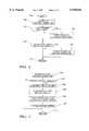
- FIG. 1is a general powertrain diagram with data recording hardware in accord with the preferred embodiment of this invention
- FIGS. 2-5are computer flow diagrams illustrating a flow of data recording operations of the hardware of FIG. 1;
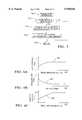
- FIGS. 6A, 6B, and 6Care parameter diagrams illustrating calibrated relationships between vehicle parameter values and trigger thresholds referenced through the operations of the routines of FIGS. 2-5.
- automotive vehicle powertrainincludes schematically illustrated internal combustion engine 10 mechanically linked to transmission 12 having transmission output shaft 30 mechanically coupled to driven vehicle wheels (not shown).
- the enginereceives intake air through intake air bore 13 in which is rotatably disposed intake air valve 26 of the rotary or butterfly type, the angular position of which is manually controlled by a vehicle operator or is electronically controlled by an electronic throttle control (ETC) system in which a current command i a issued by an actuator driver 27 is applied to a rotary actuator 25, such as a conventional step motor or DC motor having an output shaft linked to the valve 26 to rotate the valve to a position providing a desired degree of restriction to intake air passing through the bore 13.
- ETCelectronic throttle control
- the rotational position of the valve 26is transduced by rotary displacement sensor 28 of any conventional type such as a redundant potentiometric position sensor having "m" redundant conventional transducer circuits each providing substantially an independent output signal indicating angular displacement of the valve 26 away from a rest position.
- rotary displacement sensor 28of any conventional type such as a redundant potentiometric position sensor having "m" redundant conventional transducer circuits each providing substantially an independent output signal indicating angular displacement of the valve 26 away from a rest position.
- the redundant position sensing hardware elements 40 and 42 of FIG. 1 of copending U.S. patent application Ser. No. 08/361,089, filed Dec. 21, 1994providing a pair of substantially independent valve position output signals may be provided as sensor 28 of FIG. 1 in which "m" is set to two.
- Intake air passing the valve 26is received in intake manifold 11 for distribution to engine cylinders (not shown).
- Intake manifold absolute air pressureis transduced by pressure sensor 29 of a conventional type into output signal MAP.
- Engine coolantis circulated through a standard circulation system in which is disposed temperature sensor 24 in the form of a conventional thermocouple or thermistor for transducing coolant temperature into output signal Te.
- Accelerator pedal 14is manually depressed away from a rest position by a vehicle operator indicating a desired engine operating level, such as a desired engine output torque level.
- the degree of pedal depression away from a rest positionis transduced by circuitry included within sensor circuit 16 which may include "n" redundant position transducers of the potentiometric type having a corresponding "n” substantially redundant output signals indicating the pedal displacement.
- the sensor circuit 16further may include a pedal force switch (not shown) having binary output signal PFS set to a low voltage level in the absence of substantial displacement of the pedal 14 away from said rest position and otherwise set to a high voltage output level.
- a pedal force switch(not shown) having binary output signal PFS set to a low voltage level in the absence of substantial displacement of the pedal 14 away from said rest position and otherwise set to a high voltage output level.
- the "n" substantially redundant pedal position sensorsmay take the form of sensors 20, 22, and 24 of FIGS. 1 and 2 of copending U.S. patent application Ser. No. 08/361,089, filed Dec. 21, 1994 in which "n” is set to three.
- a vehicle speed signal VEHSPDis provided such as may be resolved from an averaging of wheel speed of undriven vehicle wheels or as a function of the rate of rotation of transmission output shaft 30 using standard rotational speed sensors (not shown).
- the intake airis combined with an injected quantity of fuel and is delivered for combustion in engine cylinders (not shown) for reciprocally driving pistons within the cylinders, the pistons being mechanically linked to an engine output shaft 32, such as a crankshaft, to rotate the engine output shaft which may be linked through a torque converter mechanism (not shown) to the transmission 12 for driving the transmission in a manner well-understood in the art.
- a sensor 34which is of the Hall effect, variable reluctance or magnetoresistive type, is fixedly disposed relative to the output shaft 32 in proximity to the teeth or notches thereon to transduce passage of the teeth or notches into sensor output signal RPM, the frequency of which signal is proportional to engine speed.
- a powertrain control module PCM 36includes such conventional elements as a central processing unit CPU 42 having an arithmetic logic unit ALU 44 for carrying out arithmetic and logic functions, an input/output unit I/O 52 for managing passage of data between the CPU 42 and external sensors, transducers and indicators, and various well-known memory devices including read only memory devices ROM 50 for permanent data storage including storage of the steps making up various control, diagnostic, and maintenance routines, random access memory RAM 48 for temporary data storage, and more permanent memory devices, such as electronically erasable programmable read only memory devices EEPROM 46 or conventional flash memory devices for long term read and write storage functions.
- the PCM 36is electrically energized by ignition power manually applied by a vehicle operator, such as through manual rotation of an ignition cylinder to an "ON" position.
- the PCM 36reads a plurality of control, diagnostic, and maintenance routines from ROM 50 and executes, on an instruction-by instruction basis, the operations of such routines. Included in such routines are routines to read current engine parameter values, as indicated by PCM input signals PPS, PFS, TEMP, MAF, TP, MAP, RPM, VEHSPD, and WHLSPD, and to generate and issue control signals to various actuators and indicators.
- conventional fuel control operationsare periodically carried out, such as prior to each engine cylinder expansion stroke, to generate a fueling command in the form of a pulsewidth PW f the duration of which indicates a desired fuel injector open time during which open time pressurized fuel is admitted by a fuel injector 20 into an intake runner of an active engine cylinder, as is generally understood in the art.
- the command PW fis issued to a fuel controller 18 for generating a corresponding current command i f issued to an active injector 20 to drive the injector to an open orientation for the duration of PW f .
- the control operationsfurther include operations for generating a desired intake air valve rotational position and issuing a command PW a to actuator driver 27 which takes the form of a conventional H bridge current driver for applying drive current i a to the actuator 25.
- the command PW amay be determined as a function of the n PPS signals and other values indicating the state of certain engine control operations, such as idle speed control, traction control, or cruise control operations which influence a desired intake air valve position.
- the duty cycle of PWais substantially proportional to a desired degree of rotation of the intake air valve away from a rest position.
- control operationsinclude ignition timing operations for controlling the timing of ignition of the air/fuel mixture in the engine cylinders to vary engine output torque as a function of engine operating conditions, wherein a desired timing command EST is issued to an ignition controller 38 which times issuance of ignition control current signal i s to an active engine cylinder to time the ignition of the air/fuel mixture therein, as is generally understood in the art.
- routinesmay be repeatedly executed while the PCM is active, with individual control, diagnostic and maintenance operations of such routines initiated following enabled timer and event based PCM interrupts, as is generally understood in the art. Included with such interrupts is a timer interrupt enabled to occur about every 18.75 milliseconds while the PCM 36 is operating. Upon occurrence of such interrupt, the CPU 42 automatically references an interrupt vector from ROM 50 indicating the starting point of a service routine to service the interrupt.
- Such interrupt service routineincludes a series of instructions which are executed in an instruction-by-instruction format for carrying out the operations generally illustrated in FIGS. 2-4, beginning at a step 200 of the operations of FIG. 2 and proceeding to carry out any control and diagnostic operations, including engine intake air valve control operations for varying the position of valve 26 of FIG. 1 in response to, among other inputs, a sensed degree of depression of pedal 14 away from a rest position, as described.
- control and diagnostic operationsmay take the form of any conventionally-known control and diagnostic operations. Following completion of such operations, data storage operations in accord with this invention are carried out.
- a three state data analysis and storage procedureIn a first state, termed an "active" state, relevant data is periodically packed and stored into a reserved area of a volatile memory device. The reserved area is of a limited size. When the reserved area is filled with such data, the oldest data is overwritten. A record of most recent relevant vehicle data is thereby maintained at all times while the vehicle is operating. While such storage operations of the active state are going on, repeated checks are made for occurrence of trigger conditions which are generally any conditions indicating that the stored data may be required for analysis of vehicle operation.
- a second stateis entered, termed the "suspended" state.
- the suspended statedata storage operations are suspended and a confirmation procedure for confirming that the stored data indeed will be required is carried out.
- the confirmation proceduremonitors vehicle operating conditions to determine whether the operating state of the vehicle has changed in a manner indicating a failure condition. If such condition is determined to have occurred, a third state is entered, termed the “terminated” state in which the stored data is transferred, as soon as convenient and before any significant chance of data loss, to more permanent memory devices so that it may be available for analysis for a substantial period of time including a time after the vehicle is no longer being operated.
- the terminal statethe operations of both the active and suspended states, including data storage operations, may be discontinued to ensure no loss of the stored data.
- the active statemay be resumed.
- the operations of the suspended stateestablish that no failure condition has occurred
- the active stateis resumed and data storage operations continue in the described manner.
- the limited memory storage capacity typical of automotive vehiclesis efficiently put to use securely record up-to-date relevant operating data, and the critical "permanent" memory devices are only put to use to store the data following confirmation that certain vehicle operating events have occurred.
- data storage operationsare carried out by, following the described step 202, proceeding to determine if data logging operations are currently required at a next step 204.
- data logging operationsare required periodically.
- data logging operationsmay be required synchronous with engine operating events, such as following a predetermined number of engine cylinder events.
- data logging operationsare required once for every six times step 204 is executed.
- Trigger statusis the status of conditions used to transfer between the data analysis and storage states of this embodiment. Trigger status includes an "invalid" status in which no valid trigger condition has been detected, a “conditionally true” status in which a trigger condition may have occurred but requires confirmation, and a "valid" status in which a trigger condition has been confirmed. If trigger status is "invalid,” then a set of data indicating current engine parameter information is stored at steps 304-310. It should be pointed out that, in this embodiment, trigger status is initialized upon application of ignition power to the PCM 36 of FIG. 1, to "invalid.”
- input signal valueswhich may include any automotive vehicle parameter values, whether directly measured using a sensor or transducer, or whether indirectly estimated or predicted, are read at a next step 304.
- signal valuesinclude values of the described signals PPS, PFS, WHLSPD, VEHSPD, RPM, MAP, MAF, TP, TEMP, each of which may have redundant values.
- the read input signal valuesare next packed, through execution of any commercially available data storage packing procedure, into a block of data requiring minimum storage area in RAM 48 at a next step 306.
- un-informational data bytes or wordsmay be removed from the data and the data compacted into a minimum size data block at the step 306, to maximize the amount of data that may be stored into the area of memory allocated for use for the data storage operations of this embodiment.
- the packed datais next stored in a temporary storage device at a step 308, such as conventional RAM device 48 of FIG. 1. This provides temporary, high reliability storage of data until it can be determined whether the data should be transferred to more permanent storage devices, as will be described.
- a pointerfor pointing to a next available block of the memory device that has been allocated for use in the data storage operations of FIG. 3, is updated at a step 310 to point to a next available block of volatile memory.
- block after block of packed dataare stored in series in a reserved block of volatile memory of limited size.
- the pointerpoints to the next available block. Once the reserved area is full, the pointer begins back at the first stored block and allows for the oldest data to be overwritten with any new block of packed data to be stored at the step 308.
- trigger condition analysisprovides for monitoring of vehicle operating conditions to determine whether a condition requiring permanent storage of the block of data may be required. Such analysis is carried out approximately every 37.5 milliseconds while the PCM 36 is operating which, in this embodiment, is every other iteration of the analysis of step 208.
- trigger condition analysis operationsare next carried out at a step 210 by proceeding to the operations of FIG. 4, beginning at a step 400 and proceeding to calculate or read a vehicle speed value at a step 402.
- Vehicle speedmay be calculated as a function of individual wheel speed values read at the described step 304, or as a function of transmission output shaft 30 (FIG. 1) output rate of rotation, or may be read as a filtered version of the described signal VEHSPD of FIG. 1.
- vehicle accelerationis determined at a next step 404, for example as a time rate of change in vehicle speed between the current vehicle speed and a predetermined plurality of prior determined vehicle speed values.
- Current throttle position and pedal position valuesare next referenced at a step 406, representing respectively the current position of the accelerator pedal 14 (FIG. 1) away from its rest position, and current position of the intake air valve 26 away from a rest position.
- Such current throttle and pedal position valuesmay be resolved in any conventional manner providing for an accurate pedal and throttle position indication, such as through filtering of the plurality of redundant position input signals and averaging the filtered signals to arrive at one representative position indication.
- a plurality of trigger thresholdsare next determined at a step 408.
- the trigger thresholdsare determined as a function of current vehicle operating conditions.
- the trigger thresholdsrepresent levels of various vehicle operating conditions above which the conditions are of a nature requiring entry into the second data analysis and logging state, termed the suspended state, as described.
- a first trigger thresholdis a vehicle acceleration threshold as is determined in this embodiment as a function of the position of pedal 14 (FIG. 1) away from a rest position as illustrated by the curve 602 of FIG. 6A.
- curve 602 of FIG. 6Aillustrates a representative calibration relationship between a vehicle acceleration threshold and pedal position, wherein the vehicle acceleration threshold varies in proportion to pedal displacement away from its rest position. For minor depression of the pedal 14, the acceleration threshold will be small. For substantial depression of the pedal 14, the acceleration threshold will be large.
- the acceleration thresholdprovides that a switch from the active to the suspended state will occur when vehicle acceleration is relatively large in proportion to the degree of depression of the pedal 14.
- the specific relationship between pedal displacement and acceleration thresholdmay be determined for a given vehicle application, through a calibration procedure responsive to vehicle acceleration conditions under which it would be desirable to provide for permanent storage of vehicle operating parameter data.
- a second trigger thresholdis a vehicle deceleration threshold as is determined in this embodiment as a function proportional to vehicle speed as illustrated in curve 304 of FIG. 6B, which is a representative calibrated relationship between the deceleration threshold and vehicle speed. For low vehicle speed, the deceleration threshold of curve 604 is relatively small, whereas for high vehicle speed, the deceleration threshold of curve 604 is relatively large.
- the deceleration thresholdprovides that when relatively small vehicle deceleration occurs while traveling slowly, or when a relatively large vehicle deceleration occurs while traveling quickly the suspended state will be enabled.
- the specific relationship between vehicle speed and deceleration thresholdmay be determined for a given vehicle application, through a conventional calibration procedure responsive to vehicle deceleration conditions under which it would be desirable to provide for permanent storage of vehicle operating parameter data.
- a third trigger thresholdis a intake air valve (throttle) position threshold determined as a function proportional to the position of the pedal 14 (FIG. 1) away from a rest position as illustrated by curve 606 of FIG. 6C, which is a representative calibrated relationship between the throttle position threshold and pedal position.
- the throttle position thresholdis relatively small, whereas for large pedal depression, the throttle position is relatively large.
- the throttle position thresholdprovides that when the opening of the intake air valve (throttle) 26 (FIG. 1) is large relative to the degree of depression of the pedal 14, the suspended state will be enabled.
- the specific relationship between pedal position and the throttle position thresholdmay be determined for a given vehicle application, through a conventional calibration procedure by evaluating the relationship between pedal and throttle position and the conditions under which it would be desirable to provide for permanent storage of vehicle operating parameter data.
- the trigger thresholdsmay be stored, following calibration thereof, in ROM 50 (FIG. 1) in the form of schedules or lookup tables.
- Each schedule (or lookup table)includes indexed trigger threshold values.
- the indicesare pedal position values for the acceleration and throttle position threshold schedules, and are vehicle speed values for the deceleration schedules.
- the trigger thresholdsmay be calculated by referencing stored calibrated functions describing calibrated relationships between vehicle operating parameters and corresponding threshold values, i.e. stored functions representing relationships such as those of curves 602, 604, and 606 of respective FIGS. 6A, 6B, and 6C.
- Te functionsmay be stored in ROM 50 (FIG. 1).
- each thresholdis compared to the current value of the corresponding vehicle operating parameter at a next step 410.
- Positive vehicle accelerationis compared to the acceleration trigger threshold, and if the acceleration is negative (deceleration), it is compared to the deceleration threshold, and throttle position is compared to the determined throttle position threshold. If the magnitude of any of the current vehicle parameter values exceeds its corresponding threshold as determined at the step 410, the second data analysis and storage state, described as the suspended state, is entered. Entry into this state is indicated by setting the trigger status to "conditionally true" at a step 412.
- the trigger statusis examined at a next step 414. If the trigger status is "invalid" as determined at the step 414, then the current state is the "active" data analysis and logging state in which data is periodically logged and trigger conditions periodically examined, and accordingly a trigger event timer is reset at a next step 416. After resetting the trigger event timer, which indicates that no trigger condition has been detected, the operations of FIG. 4 are concluded by returning, via a next step 430, to continue execution of the operations of the routine of FIG. 2.
- trigger statusis not "invalid,” then the three state trigger status is analyzed at a next step 418 to determine if it is "valid,” indicating that the current state is the "terminated” state. If the trigger status is determined to be "valid” at the step 418, the operations of the routine of FIG. 4 are concluded, and the described step 430 is next carried out. If the trigger status is determined at the step 418 to not be “valid,” then the trigger status must be "conditionally true,” corresponding to the suspended data storage and analysis state, and conditions are then examined to determine if confirmation can be made that the trigger status is indeed “valid,” providing that the stored data should be preserved in more permanent memory, as described.
- a step 420is next executed to determine if an electronic throttle control (ETC) system fault has been detected. If so, the trigger flag is next set to valid at a next step 422.
- ETC faultmay be any fault condition related to the ETC system which is conventionally detectable and which could impact ETC system performance. If such a fault condition is detected, a second indication of a condition (beyond the condition detected at the described step 410) requiring transfer of stored data to more permanent memory in accord with the principles of this invention has been detected.
- the permanent data storage conditionis confirmed and the terminated state is entered by proceeding from the step 420 to the step 422 to set trigger status to "valid" to mark operation in the third data storage and analysis state (the terminated state).
- data stored in RAM at the described step 308may immediately be transferred, such as on an "entry by entry” basis into more permanent memory such as electronically-erasable programmable read only memory EEPROM, for example at a next step 421 (not shown) simply by storing each entry into the reserved RAM 48 (FIG. 1) into a corresponding position reserved in EEPROM 46 (FIG. 1).
- the datamay be transferred from RAM 48 (FIG. 1) into flash memory, for example at the end of a vehicle ignition cycle, as will be described.
- step 422more data may be gathered and stored in RAM 48 via the steps of FIG. 3, by setting trigger status back to "invalid" to return to the active data storage and analysis state at a step following the step 421.
- the first stateis not resumed following the step 422 until the next vehicle ignition cycle.
- step 430is executed to conclude the operations of the routine of FIG. 4.
- step 420if an ETC fault is not determined to be present, further conditions are analyzed at a next step 424. More specifically, if engine speed RPM is substantially zero, as determined at the step 424 indicating engine operation is terminated, the described step 422 is executed to enter the terminated state to provide for transfer of the parameter data from volatile to more permanent, as described.
- step 410if engine speed is substantially zero following occurrence of one of the trigger conditions analyzed at the described step 410, it is assumed that the vehicle parameter data stored in RAM at the step 308 may be useful in analyzing vehicle operation in accord with the principles of this invention, so the third (terminated) state is entered. However, if engine speed is not substantially zero at the step 424, then further conditions are analyzed at a next step 426.
- the predetermined period of timemay be determined through a conventional calibration procedure and is set to about thirty seconds in this embodiment, then too much time has elapsed in the second (suspended) state without any confirmation that the trigger event detected to be present at the step 410 was a valid trigger event, i.e. was followed by a detected fault condition or was followed by an engine shutdown, to assume the trigger was valid. Accordingly, the trigger is assumed to be a false trigger, and the state is switched back to "active" (corresponding to trigger flag set to "invalid") so that more data may be logged while waiting for any valid trigger event.
- trigger statusis next set to "invalid" at a step 428 signaling re-entry into the active data storage and analysis state and then the described step 430 is executed. If thirty seconds have not elapsed since the trigger flag was last reset at the step 416, then the operations proceed directly from the step 426 to the step 430. Upon executing the described step 430, the operations resume at step 212 of the routine of FIG. 2, to return to any prior operations, such as background diagnostic or maintenance operations in accordance with conventional powertrain control.
- PCM power-down operationsare illustrated in a step by step manner, beginning at a step 500. Such operations may be executed following a vehicle operator-initiated power down operation, or following any other powertrain power down procedure in which the PCM is to be disabled and engine speed reduced to zero. The operations proceed from the step 500 to a next step 510 at which the trigger status is analyzed.
- all filled data blocks in the reserved portion of RAM 48are transferred, using any conventional memory transfer procedure, to a corresponding block of flash memory at a next step 512.
- a checksumis next calculated in any conventional manner, such as by adding all transferred data values together and storing the least significant byte of the sum of such values in flash memory as the last entry thereof, for conventionally understood data security benefits.
- the stored datathen is substantially insensitive to the loss of power to the PCM 36 of FIG. 1 and remains available for off-line analysis to establish the operating condition of the vehicle prior to the detection of an ETC fault or prior to engine shut down to substantially zero engine speed, or indeed prior to occurrence of any other vehicle operating condition that may tend to confirm the trigger condition.
Landscapes
- Physics & Mathematics (AREA)
- General Physics & Mathematics (AREA)
- Combined Controls Of Internal Combustion Engines (AREA)
Abstract
Description
Claims (14)
Priority Applications (1)
| Application Number | Priority Date | Filing Date | Title |
|---|---|---|---|
| US08/736,178US5948026A (en) | 1996-10-24 | 1996-10-24 | Automotive data recorder |
Applications Claiming Priority (1)
| Application Number | Priority Date | Filing Date | Title |
|---|---|---|---|
| US08/736,178US5948026A (en) | 1996-10-24 | 1996-10-24 | Automotive data recorder |
Publications (1)
| Publication Number | Publication Date |
|---|---|
| US5948026Atrue US5948026A (en) | 1999-09-07 |
Family
ID=24958827
Family Applications (1)
| Application Number | Title | Priority Date | Filing Date |
|---|---|---|---|
| US08/736,178Expired - LifetimeUS5948026A (en) | 1996-10-24 | 1996-10-24 | Automotive data recorder |
Country Status (1)
| Country | Link |
|---|---|
| US (1) | US5948026A (en) |
Cited By (89)
| Publication number | Priority date | Publication date | Assignee | Title |
|---|---|---|---|---|
| US6073063A (en)* | 1997-02-06 | 2000-06-06 | Ford Global Technologies, Inc. | Automotive data recording device |
| US6076038A (en)* | 1996-07-16 | 2000-06-13 | Siemens Aktiengesellschaft | Computer unit for a control device in a motor vehicle |
| US6115666A (en)* | 1996-06-21 | 2000-09-05 | Outboard Marine Corporation | Method and apparatus for creating a profile of operating conditions of an engine |
| US6208917B1 (en) | 1999-12-23 | 2001-03-27 | Daimlerchrysler Corporation | Ambient temperature/inlet air temperature sensor dither |
| US6295488B1 (en)* | 1997-06-23 | 2001-09-25 | Eurocopter | Method and device for locating faults and malfunctions in a complex system |
| US6298290B1 (en)* | 1999-12-30 | 2001-10-02 | Niles Parts Co., Ltd. | Memory apparatus for vehicle information data |
| US6339742B2 (en)* | 1995-05-15 | 2002-01-15 | Detroit Diesel Corporation | System and method for engine data trending and analysis |
| US6347276B1 (en)* | 2000-09-13 | 2002-02-12 | Detroit Diesel Corporation | Method and system for reducing the time required to power down engine controller with faulty EEPROM |
| US6356824B1 (en) | 2001-01-23 | 2002-03-12 | Meritor Heavy Vehicle Technology, Llc | Vehicle systems data storage |
| US6363304B1 (en) | 2000-06-12 | 2002-03-26 | Meritor Heavy Vehicle Technology, Llc | Personal data computer for vehicle monitoring |
| US6430488B1 (en)* | 1998-04-10 | 2002-08-06 | International Business Machines Corporation | Vehicle customization, restriction, and data logging |
| US20020107912A1 (en)* | 2001-02-08 | 2002-08-08 | Lear Corporation | Motor vehicle drive recorder system which records motor vehicle data proximate an event declared by a motor veicle occupant |
| US6438511B1 (en)* | 2000-11-14 | 2002-08-20 | Detroit Diesel Corporation | Population data acquisition system |
| EP1187008A3 (en)* | 2000-04-10 | 2002-09-11 | Teledyne Technologies Incorporated | System and method for specification of trigger logic conditions |
| US6498972B1 (en)* | 2002-02-13 | 2002-12-24 | Ford Global Technologies, Inc. | Method for operating a pre-crash sensing system in a vehicle having a countermeasure system |
| USRE37966E1 (en)* | 1996-07-16 | 2003-01-14 | Siemens Aktiengesellschaft | Computer unit for a control device in a motor vehicle |
| US6516251B1 (en) | 2001-01-23 | 2003-02-04 | Meritor Heavy Vehicle Technology, Llc. | Automated vehicle shutdown sequence |
| US6519519B1 (en) | 2002-02-01 | 2003-02-11 | Ford Global Technologies, Inc. | Passive countermeasure methods |
| US6535802B1 (en) | 2002-01-25 | 2003-03-18 | Meritor Heavy Vehicle Technology, Llc | Quick check vehicle diagnostics |
| US6542077B2 (en) | 1993-06-08 | 2003-04-01 | Raymond Anthony Joao | Monitoring apparatus for a vehicle and/or a premises |
| US6549130B1 (en) | 1993-06-08 | 2003-04-15 | Raymond Anthony Joao | Control apparatus and method for vehicles and/or for premises |
| US20030076981A1 (en)* | 2001-10-18 | 2003-04-24 | Smith Gregory Hugh | Method for operating a pre-crash sensing system in a vehicle having a counter-measure system |
| US6587768B2 (en) | 2001-08-08 | 2003-07-01 | Meritor Heavy Vehicle Technology, Llc | Vehicle inspection and maintenance system |
| US6587046B2 (en) | 1996-03-27 | 2003-07-01 | Raymond Anthony Joao | Monitoring apparatus and method |
| US20030139864A1 (en)* | 2002-01-24 | 2003-07-24 | Ford Global Technologies, Inc. | Post collision restraints control module |
| US6601015B1 (en)* | 1998-03-02 | 2003-07-29 | Cummins Engine Company, Inc. | Embedded datalogger for an engine control system |
| US6622071B2 (en)* | 1999-12-16 | 2003-09-16 | Mannesmann Vdo Ag | Acceleration monitoring method for a longitudinal dynamics open-loop or closed-loop controller in motor vehicles |
| US20030200022A1 (en)* | 2002-02-05 | 2003-10-23 | Michael Streichsbier | Apparatus and method for simultaneous monitoring, logging, and controlling of an industrial process |
| US6681987B1 (en) | 2000-03-09 | 2004-01-27 | Meritor Heavy Vehicle Systems, Llc | Smart card system for heavy vehicles |
| US20040078123A1 (en)* | 2002-10-17 | 2004-04-22 | Igloi Tamas M. | Aircraft avionics maintenance diagnostics data download transmission system |
| US20040083040A1 (en)* | 2002-10-28 | 2004-04-29 | Thomas Parrott | Vehicle data retrieval system |
| US20040111200A1 (en)* | 2001-11-29 | 2004-06-10 | Rao Manoharprasad K. | Vehicle sensing based pre-crash threat assessment system |
| US6775605B2 (en) | 2001-11-29 | 2004-08-10 | Ford Global Technologies, Llc | Remote sensing based pre-crash threat assessment system |
| US6831572B2 (en) | 2002-01-29 | 2004-12-14 | Ford Global Technologies, Llc | Rear collision warning system |
| US20050190656A1 (en)* | 2004-02-27 | 2005-09-01 | Fuji Jukogyo Kabushiki Kaisha | Data recording apparatus and data recording method |
| US20050278214A1 (en)* | 2002-10-25 | 2005-12-15 | Yoshiaki Takida | Toll road charge collection system using artificial satellite, charge collecting machine, and charge collecting method |
| US7009500B2 (en) | 2002-02-13 | 2006-03-07 | Ford Global Technologies, Llc | Method for operating a pre-crash sensing system in a vehicle having a countermeasure system using stereo cameras |
| US20060095199A1 (en)* | 2004-11-03 | 2006-05-04 | Lagassey Paul J | Modular intelligent transportation system |
| US20060092043A1 (en)* | 2004-11-03 | 2006-05-04 | Lagassey Paul J | Advanced automobile accident detection, data recordation and reporting system |
| US7111489B2 (en) | 2004-05-28 | 2006-09-26 | Daimlerchrysler Corporation | Tone wheel sensor tester |
| US20070032930A1 (en)* | 2005-08-08 | 2007-02-08 | Calsonic Kansei Corporation | Vehicle data recording device |
| US20070164142A1 (en)* | 2001-12-26 | 2007-07-19 | Castronovo Charles A | Destruction Method With 45 Degree Feeding |
| US7277010B2 (en) | 1996-03-27 | 2007-10-02 | Raymond Anthony Joao | Monitoring apparatus and method |
| US20080059020A1 (en)* | 2006-08-31 | 2008-03-06 | Hitachi, Ltd. | Data Recorder For Vehicle |
| US20080154712A1 (en)* | 2006-12-13 | 2008-06-26 | Crown Equipment Corporation | Fleet management system |
| US7397363B2 (en) | 1993-06-08 | 2008-07-08 | Raymond Anthony Joao | Control and/or monitoring apparatus and method |
| US20090248241A1 (en)* | 2008-03-31 | 2009-10-01 | Renesas Technology Corp. | Automotive recorder |
| US20090306848A1 (en)* | 2005-07-01 | 2009-12-10 | Hiroji Kohsaka | Driving recorder |
| US20090326782A1 (en)* | 2008-04-21 | 2009-12-31 | Honeywell International Inc. | Aircraft gas turbine engine controller with removable memory and diagnostic system and method therefor |
| US20100023207A1 (en)* | 2007-04-02 | 2010-01-28 | Toyota Jidosha Kabushiki Kaisha | Vehicle information recording system |
| US20100039247A1 (en)* | 2006-12-13 | 2010-02-18 | Ziegler Ronald L | Impact sensing usable with fleet management system |
| US20100152964A1 (en)* | 2005-06-25 | 2010-06-17 | Akihiro Hashimoto | Driving recorder |
| US20100228428A1 (en)* | 2006-12-13 | 2010-09-09 | Crown Equipment Corporation | Information system for industrial vehicles |
| US20100318258A1 (en)* | 2005-07-01 | 2010-12-16 | Tsuyoshi Katayama | Driving recorder |
| US20110022442A1 (en)* | 2006-12-13 | 2011-01-27 | Crown Equipment Corporation | Information system for industrial vehicles including cyclical recurring vehicle information message |
| US20110040440A1 (en)* | 2009-08-12 | 2011-02-17 | Crown Equipment Corporation | Information system for industrial vehicles |
| US20110166743A1 (en)* | 2010-01-07 | 2011-07-07 | Denso Corporation | Vehicular information storage apparatus and vehicle diagnosis system |
| GB2477205A (en)* | 2010-01-19 | 2011-07-27 | Boeing Co | Monitoring vehicle conditions |
| US20110191392A1 (en)* | 2010-02-01 | 2011-08-04 | Denso Corporation | Data management apparatus, data management program and data management system |
| US20110282518A1 (en)* | 1999-12-29 | 2011-11-17 | Hamrick Marvin R | G.P.S. Management System |
| US20110288722A1 (en)* | 2009-07-24 | 2011-11-24 | Harley-Davidson Motor Company Group, LLC | Vehicle calibration using data collected during normal operating conditions |
| CN1661349B (en)* | 2004-02-27 | 2011-12-07 | 富士重工业株式会社 | Data recording apparatus and data recording method |
| EP1628011A4 (en)* | 2003-08-01 | 2012-01-25 | Nissan Diesel Motor Co | Diagnostic information collecting device |
| US20120035838A1 (en)* | 2009-02-16 | 2012-02-09 | Johannes Zeidler | Method and device for acquiring and transmitting operating data of an internal combustion engine |
| US8369967B2 (en) | 1999-02-01 | 2013-02-05 | Hoffberg Steven M | Alarm system controller and a method for controlling an alarm system |
| US8416067B2 (en) | 2008-09-09 | 2013-04-09 | United Parcel Service Of America, Inc. | Systems and methods for utilizing telematics data to improve fleet management operations |
| US20140053030A1 (en)* | 2012-08-16 | 2014-02-20 | Hyundai Motor Company | Method and system for preventing loss of trip data in vehicle |
| US8892495B2 (en) | 1991-12-23 | 2014-11-18 | Blanding Hovenweep, Llc | Adaptive pattern recognition based controller apparatus and method and human-interface therefore |
| US9075136B1 (en) | 1998-03-04 | 2015-07-07 | Gtj Ventures, Llc | Vehicle operator and/or occupant information apparatus and method |
| US9208626B2 (en) | 2011-03-31 | 2015-12-08 | United Parcel Service Of America, Inc. | Systems and methods for segmenting operational data |
| GB2527811A (en)* | 2014-07-03 | 2016-01-06 | Delphi Internat Operations Luxembourg S Ã R L | Vehicle data acquisition device and method |
| JP2016045790A (en)* | 2014-08-25 | 2016-04-04 | 株式会社デンソー | Information recording device for vehicle |
| US20160131068A1 (en)* | 2014-11-10 | 2016-05-12 | Caterpillar Inc. | Engine system utilizing modal weighted engine optimization |
| US9805521B1 (en) | 2013-12-03 | 2017-10-31 | United Parcel Service Of America, Inc. | Systems and methods for assessing turns made by a vehicle |
| US10011247B2 (en) | 1996-03-27 | 2018-07-03 | Gtj Ventures, Llc | Control, monitoring and/or security apparatus and method |
| US10152876B2 (en) | 1996-03-27 | 2018-12-11 | Gtj Ventures, Llc | Control, monitoring, and/or security apparatus and method |
| US10309788B2 (en) | 2015-05-11 | 2019-06-04 | United Parcel Service Of America, Inc. | Determining street segment headings |
| US10361802B1 (en) | 1999-02-01 | 2019-07-23 | Blanding Hovenweep, Llc | Adaptive pattern recognition based control system and method |
| US10546441B2 (en) | 2013-06-04 | 2020-01-28 | Raymond Anthony Joao | Control, monitoring, and/or security, apparatus and method for premises, vehicles, and/or articles |
| US10562492B2 (en) | 2002-05-01 | 2020-02-18 | Gtj Ventures, Llc | Control, monitoring and/or security apparatus and method |
| GB2579558A (en)* | 2018-12-03 | 2020-07-01 | Tomtom Telematics Bv | System and method for providing an indication of driving performance |
| US10713860B2 (en) | 2011-03-31 | 2020-07-14 | United Parcel Service Of America, Inc. | Segmenting operational data |
| US10796268B2 (en) | 2001-01-23 | 2020-10-06 | Gtj Ventures, Llc | Apparatus and method for providing shipment information |
| CN112362323A (en)* | 2020-10-27 | 2021-02-12 | 华能国际电力股份有限公司 | Data storage method of vibration online monitoring and fault diagnosis system of steam turbine generator unit |
| US11130409B1 (en) | 2017-11-30 | 2021-09-28 | Hydro-Gear Limited Partnership | Automatic performance learning system for utility vehicles |
| US11225404B2 (en) | 2006-12-13 | 2022-01-18 | Crown Equipment Corporation | Information system for industrial vehicles |
| US11482058B2 (en) | 2008-09-09 | 2022-10-25 | United Parcel Service Of America, Inc. | Systems and methods for utilizing telematics data to improve fleet management operations |
| US12296833B2 (en) | 2018-12-03 | 2025-05-13 | Bridgestone Mobility Solutions, B.V. | System and method for providing an indication of driving performance |
| US12380373B2 (en) | 2009-09-01 | 2025-08-05 | Crown Equipment Corporation | Information system for industrial vehicles including cyclical recurring vehicle information message |
Citations (7)
| Publication number | Priority date | Publication date | Assignee | Title |
|---|---|---|---|---|
| US5050080A (en)* | 1988-09-28 | 1991-09-17 | Fuji Jukogyo Kabushiki Kaisha | Diagnostic system for a motor vehicle |
| US5276619A (en)* | 1990-04-06 | 1994-01-04 | Nippondenso Co., Ltd. | Electronic control system with self-diagnostic function for use in motor vehicle |
| US5305216A (en)* | 1990-11-01 | 1994-04-19 | Nissan Motor Co., Ltd. | Event detector used vehicle control apparatus |
| US5311430A (en)* | 1991-10-11 | 1994-05-10 | Nissan Motor Co., Ltd. | Vehicle operation data recording apparatus |
| US5388045A (en)* | 1992-08-27 | 1995-02-07 | Nippondenso Co., Ltd. | Self-diagnostic apparatus of vehicles |
| US5546306A (en)* | 1992-10-27 | 1996-08-13 | Honda Giken Kogyo Kabushiki Kaisha | Multiple processor throttle control apparatus for an internal combustion engine |
| US5752211A (en)* | 1993-11-24 | 1998-05-12 | Nissan Motor Co., Ltd. | Control system for distributing drive torque between front and rear wheels of vehicle |
- 1996
- 1996-10-24USUS08/736,178patent/US5948026A/ennot_activeExpired - Lifetime
Patent Citations (7)
| Publication number | Priority date | Publication date | Assignee | Title |
|---|---|---|---|---|
| US5050080A (en)* | 1988-09-28 | 1991-09-17 | Fuji Jukogyo Kabushiki Kaisha | Diagnostic system for a motor vehicle |
| US5276619A (en)* | 1990-04-06 | 1994-01-04 | Nippondenso Co., Ltd. | Electronic control system with self-diagnostic function for use in motor vehicle |
| US5305216A (en)* | 1990-11-01 | 1994-04-19 | Nissan Motor Co., Ltd. | Event detector used vehicle control apparatus |
| US5311430A (en)* | 1991-10-11 | 1994-05-10 | Nissan Motor Co., Ltd. | Vehicle operation data recording apparatus |
| US5388045A (en)* | 1992-08-27 | 1995-02-07 | Nippondenso Co., Ltd. | Self-diagnostic apparatus of vehicles |
| US5546306A (en)* | 1992-10-27 | 1996-08-13 | Honda Giken Kogyo Kabushiki Kaisha | Multiple processor throttle control apparatus for an internal combustion engine |
| US5752211A (en)* | 1993-11-24 | 1998-05-12 | Nissan Motor Co., Ltd. | Control system for distributing drive torque between front and rear wheels of vehicle |
Cited By (160)
| Publication number | Priority date | Publication date | Assignee | Title |
|---|---|---|---|---|
| US8892495B2 (en) | 1991-12-23 | 2014-11-18 | Blanding Hovenweep, Llc | Adaptive pattern recognition based controller apparatus and method and human-interface therefore |
| US6549130B1 (en) | 1993-06-08 | 2003-04-15 | Raymond Anthony Joao | Control apparatus and method for vehicles and/or for premises |
| US6542077B2 (en) | 1993-06-08 | 2003-04-01 | Raymond Anthony Joao | Monitoring apparatus for a vehicle and/or a premises |
| US7397363B2 (en) | 1993-06-08 | 2008-07-08 | Raymond Anthony Joao | Control and/or monitoring apparatus and method |
| US6339742B2 (en)* | 1995-05-15 | 2002-01-15 | Detroit Diesel Corporation | System and method for engine data trending and analysis |
| US6671614B2 (en) | 1995-05-15 | 2003-12-30 | Detroit Diesel Corporation | System and method for engine data trending and analysis |
| US10152876B2 (en) | 1996-03-27 | 2018-12-11 | Gtj Ventures, Llc | Control, monitoring, and/or security apparatus and method |
| US10011247B2 (en) | 1996-03-27 | 2018-07-03 | Gtj Ventures, Llc | Control, monitoring and/or security apparatus and method |
| US7277010B2 (en) | 1996-03-27 | 2007-10-02 | Raymond Anthony Joao | Monitoring apparatus and method |
| US6587046B2 (en) | 1996-03-27 | 2003-07-01 | Raymond Anthony Joao | Monitoring apparatus and method |
| US6115666A (en)* | 1996-06-21 | 2000-09-05 | Outboard Marine Corporation | Method and apparatus for creating a profile of operating conditions of an engine |
| US6076038A (en)* | 1996-07-16 | 2000-06-13 | Siemens Aktiengesellschaft | Computer unit for a control device in a motor vehicle |
| USRE37966E1 (en)* | 1996-07-16 | 2003-01-14 | Siemens Aktiengesellschaft | Computer unit for a control device in a motor vehicle |
| US6073063A (en)* | 1997-02-06 | 2000-06-06 | Ford Global Technologies, Inc. | Automotive data recording device |
| US6295488B1 (en)* | 1997-06-23 | 2001-09-25 | Eurocopter | Method and device for locating faults and malfunctions in a complex system |
| US6601015B1 (en)* | 1998-03-02 | 2003-07-29 | Cummins Engine Company, Inc. | Embedded datalogger for an engine control system |
| US9075136B1 (en) | 1998-03-04 | 2015-07-07 | Gtj Ventures, Llc | Vehicle operator and/or occupant information apparatus and method |
| US6430488B1 (en)* | 1998-04-10 | 2002-08-06 | International Business Machines Corporation | Vehicle customization, restriction, and data logging |
| US9535563B2 (en) | 1999-02-01 | 2017-01-03 | Blanding Hovenweep, Llc | Internet appliance system and method |
| US10361802B1 (en) | 1999-02-01 | 2019-07-23 | Blanding Hovenweep, Llc | Adaptive pattern recognition based control system and method |
| US8369967B2 (en) | 1999-02-01 | 2013-02-05 | Hoffberg Steven M | Alarm system controller and a method for controlling an alarm system |
| US6622071B2 (en)* | 1999-12-16 | 2003-09-16 | Mannesmann Vdo Ag | Acceleration monitoring method for a longitudinal dynamics open-loop or closed-loop controller in motor vehicles |
| US6208917B1 (en) | 1999-12-23 | 2001-03-27 | Daimlerchrysler Corporation | Ambient temperature/inlet air temperature sensor dither |
| US8781645B2 (en) | 1999-12-29 | 2014-07-15 | At&T Intellectual Property I, L.P. | Apparatus, systems, and methods for processing alerts relating to an in-vehicle control unit |
| US9734698B2 (en) | 1999-12-29 | 2017-08-15 | At&T Intellectual Property I, L.P. | G.P.S. management system |
| US8478453B2 (en) | 1999-12-29 | 2013-07-02 | At&T Intellectual Property I, L.P. | Apparatus, systems, and methods for processing alerts relating to an in-vehicle control unit |
| US9652973B2 (en) | 1999-12-29 | 2017-05-16 | At&T Intellectual Property I, L.P. | Apparatus, systems, and methods for processing alerts relating to an in-vehicle control unit |
| US20110282518A1 (en)* | 1999-12-29 | 2011-11-17 | Hamrick Marvin R | G.P.S. Management System |
| US8725344B2 (en) | 1999-12-29 | 2014-05-13 | At&T Intellectual Property I, L.P. | G.P.S. management system |
| US8271162B2 (en)* | 1999-12-29 | 2012-09-18 | At&T Intellectual Property I, Lp | G.P.S. management system |
| US6298290B1 (en)* | 1999-12-30 | 2001-10-02 | Niles Parts Co., Ltd. | Memory apparatus for vehicle information data |
| US6681987B1 (en) | 2000-03-09 | 2004-01-27 | Meritor Heavy Vehicle Systems, Llc | Smart card system for heavy vehicles |
| EP1187008A3 (en)* | 2000-04-10 | 2002-09-11 | Teledyne Technologies Incorporated | System and method for specification of trigger logic conditions |
| US6696930B1 (en) | 2000-04-10 | 2004-02-24 | Teledyne Technologies Incorporated | System and method for specification of trigger logic conditions |
| US6363304B1 (en) | 2000-06-12 | 2002-03-26 | Meritor Heavy Vehicle Technology, Llc | Personal data computer for vehicle monitoring |
| WO2002023458A1 (en)* | 2000-09-13 | 2002-03-21 | Detroit Diesel Corporation | Method and system for reducing the time required to power down engine controller with faulty eeprom |
| US6347276B1 (en)* | 2000-09-13 | 2002-02-12 | Detroit Diesel Corporation | Method and system for reducing the time required to power down engine controller with faulty EEPROM |
| GB2381628B (en)* | 2000-09-13 | 2005-01-05 | Detroit Diesel Corp | Method and system for reducing the time required to power down engine controller with faulty EEPROM |
| GB2381628A (en)* | 2000-09-13 | 2003-05-07 | Detroit Diesel Corp | Method and system for reducing the time required to power down engine controller with faulty EEPROM |
| US6438511B1 (en)* | 2000-11-14 | 2002-08-20 | Detroit Diesel Corporation | Population data acquisition system |
| US6516251B1 (en) | 2001-01-23 | 2003-02-04 | Meritor Heavy Vehicle Technology, Llc. | Automated vehicle shutdown sequence |
| US10796268B2 (en) | 2001-01-23 | 2020-10-06 | Gtj Ventures, Llc | Apparatus and method for providing shipment information |
| US6356824B1 (en) | 2001-01-23 | 2002-03-12 | Meritor Heavy Vehicle Technology, Llc | Vehicle systems data storage |
| US20020107912A1 (en)* | 2001-02-08 | 2002-08-08 | Lear Corporation | Motor vehicle drive recorder system which records motor vehicle data proximate an event declared by a motor veicle occupant |
| US6587768B2 (en) | 2001-08-08 | 2003-07-01 | Meritor Heavy Vehicle Technology, Llc | Vehicle inspection and maintenance system |
| US20030076981A1 (en)* | 2001-10-18 | 2003-04-24 | Smith Gregory Hugh | Method for operating a pre-crash sensing system in a vehicle having a counter-measure system |
| US6819991B2 (en) | 2001-11-29 | 2004-11-16 | Ford Global Technologies, Llc | Vehicle sensing based pre-crash threat assessment system |
| US6775605B2 (en) | 2001-11-29 | 2004-08-10 | Ford Global Technologies, Llc | Remote sensing based pre-crash threat assessment system |
| US20040111200A1 (en)* | 2001-11-29 | 2004-06-10 | Rao Manoharprasad K. | Vehicle sensing based pre-crash threat assessment system |
| US20070164142A1 (en)* | 2001-12-26 | 2007-07-19 | Castronovo Charles A | Destruction Method With 45 Degree Feeding |
| US7158870B2 (en) | 2002-01-24 | 2007-01-02 | Ford Global Technologies, Llc | Post collision restraints control module |
| US20030139864A1 (en)* | 2002-01-24 | 2003-07-24 | Ford Global Technologies, Inc. | Post collision restraints control module |
| US6535802B1 (en) | 2002-01-25 | 2003-03-18 | Meritor Heavy Vehicle Technology, Llc | Quick check vehicle diagnostics |
| US6831572B2 (en) | 2002-01-29 | 2004-12-14 | Ford Global Technologies, Llc | Rear collision warning system |
| US6519519B1 (en) | 2002-02-01 | 2003-02-11 | Ford Global Technologies, Inc. | Passive countermeasure methods |
| US7117079B2 (en)* | 2002-02-05 | 2006-10-03 | Cleaire Advanced Emission Controls, Llc | Apparatus and method for simultaneous monitoring, logging, and controlling of an industrial process |
| US20030200022A1 (en)* | 2002-02-05 | 2003-10-23 | Michael Streichsbier | Apparatus and method for simultaneous monitoring, logging, and controlling of an industrial process |
| US6498972B1 (en)* | 2002-02-13 | 2002-12-24 | Ford Global Technologies, Inc. | Method for operating a pre-crash sensing system in a vehicle having a countermeasure system |
| US7009500B2 (en) | 2002-02-13 | 2006-03-07 | Ford Global Technologies, Llc | Method for operating a pre-crash sensing system in a vehicle having a countermeasure system using stereo cameras |
| US10562492B2 (en) | 2002-05-01 | 2020-02-18 | Gtj Ventures, Llc | Control, monitoring and/or security apparatus and method |
| US20040078123A1 (en)* | 2002-10-17 | 2004-04-22 | Igloi Tamas M. | Aircraft avionics maintenance diagnostics data download transmission system |
| US6915189B2 (en) | 2002-10-17 | 2005-07-05 | Teledyne Technologies Incorporated | Aircraft avionics maintenance diagnostics data download transmission system |
| US20050278214A1 (en)* | 2002-10-25 | 2005-12-15 | Yoshiaki Takida | Toll road charge collection system using artificial satellite, charge collecting machine, and charge collecting method |
| US20040083040A1 (en)* | 2002-10-28 | 2004-04-29 | Thomas Parrott | Vehicle data retrieval system |
| EP1628011A4 (en)* | 2003-08-01 | 2012-01-25 | Nissan Diesel Motor Co | Diagnostic information collecting device |
| US20050190656A1 (en)* | 2004-02-27 | 2005-09-01 | Fuji Jukogyo Kabushiki Kaisha | Data recording apparatus and data recording method |
| EP1569175A3 (en)* | 2004-02-27 | 2006-08-02 | Fuji Jukogyo Kabushiki Kaisha | Data recording apparatus and data recording method |
| CN1661349B (en)* | 2004-02-27 | 2011-12-07 | 富士重工业株式会社 | Data recording apparatus and data recording method |
| US7111489B2 (en) | 2004-05-28 | 2006-09-26 | Daimlerchrysler Corporation | Tone wheel sensor tester |
| US20060092043A1 (en)* | 2004-11-03 | 2006-05-04 | Lagassey Paul J | Advanced automobile accident detection, data recordation and reporting system |
| US20060095199A1 (en)* | 2004-11-03 | 2006-05-04 | Lagassey Paul J | Modular intelligent transportation system |
| US9090295B2 (en) | 2004-11-03 | 2015-07-28 | The Wilfred J. and Louisette G. Lagassey Irrevocable Trust | Modular intelligent transportation system |
| US10979959B2 (en) | 2004-11-03 | 2021-04-13 | The Wilfred J. and Louisette G. Lagassey Irrevocable Trust | Modular intelligent transportation system |
| US9359018B2 (en) | 2004-11-03 | 2016-06-07 | The Wilfred J. and Louisette G. Lagassey Irrevocable Trust | Modular intelligent transportation system |
| US7348895B2 (en) | 2004-11-03 | 2008-03-25 | Lagassey Paul J | Advanced automobile accident detection, data recordation and reporting system |
| US7983835B2 (en) | 2004-11-03 | 2011-07-19 | Lagassey Paul J | Modular intelligent transportation system |
| US20100152964A1 (en)* | 2005-06-25 | 2010-06-17 | Akihiro Hashimoto | Driving recorder |
| US8280577B2 (en) | 2005-06-25 | 2012-10-02 | Horiba, Ltd. | Driving recorder |
| US20090306848A1 (en)* | 2005-07-01 | 2009-12-10 | Hiroji Kohsaka | Driving recorder |
| US8285442B2 (en)* | 2005-07-01 | 2012-10-09 | Horiba, Ltd. | Driving recorder |
| US20100318258A1 (en)* | 2005-07-01 | 2010-12-16 | Tsuyoshi Katayama | Driving recorder |
| US8452502B2 (en) | 2005-07-01 | 2013-05-28 | Japan Automobile Research Institute | Driving recorder |
| US7558656B2 (en)* | 2005-08-08 | 2009-07-07 | Calsonic Kansei Corporation | Vehicle data recording device |
| US20070032930A1 (en)* | 2005-08-08 | 2007-02-08 | Calsonic Kansei Corporation | Vehicle data recording device |
| US20080059020A1 (en)* | 2006-08-31 | 2008-03-06 | Hitachi, Ltd. | Data Recorder For Vehicle |
| US10600256B2 (en) | 2006-12-13 | 2020-03-24 | Crown Equipment Corporation | Impact sensing usable with fleet management system |
| US9984341B2 (en) | 2006-12-13 | 2018-05-29 | Crown Equipment Corporation | Information system for industrial vehicles including cyclical recurring vehicle information message |
| US11823502B2 (en) | 2006-12-13 | 2023-11-21 | Crown Equipment Corporation | Impact sensing usable with fleet management system |
| US8249910B2 (en) | 2006-12-13 | 2012-08-21 | Crown Equipment Corporation | Fleet management system |
| US11947361B2 (en) | 2006-12-13 | 2024-04-02 | Crown Equipment Corporation | Fleet management system |
| US10013815B2 (en) | 2006-12-13 | 2018-07-03 | Crown Equipment Corporation | Information system for industrial vehicles |
| US20110022442A1 (en)* | 2006-12-13 | 2011-01-27 | Crown Equipment Corporation | Information system for industrial vehicles including cyclical recurring vehicle information message |
| US20100039247A1 (en)* | 2006-12-13 | 2010-02-18 | Ziegler Ronald L | Impact sensing usable with fleet management system |
| US12210353B2 (en) | 2006-12-13 | 2025-01-28 | Crown Equipment Corporation | Fleet management system |
| US10599160B2 (en) | 2006-12-13 | 2020-03-24 | Crown Equipment Corporation | Fleet management system |
| US20080154691A1 (en)* | 2006-12-13 | 2008-06-26 | Wellman Timothy A | Fleet management system |
| US20080154712A1 (en)* | 2006-12-13 | 2008-06-26 | Crown Equipment Corporation | Fleet management system |
| US11225404B2 (en) | 2006-12-13 | 2022-01-18 | Crown Equipment Corporation | Information system for industrial vehicles |
| US20100228428A1 (en)* | 2006-12-13 | 2010-09-09 | Crown Equipment Corporation | Information system for industrial vehicles |
| US8060400B2 (en) | 2006-12-13 | 2011-11-15 | Crown Equipment Corporation | Fleet management system |
| US10810521B2 (en) | 2006-12-13 | 2020-10-20 | Crown Equipment Corporation | Information system for industrial vehicles including cyclical recurring vehicle information message |
| US8190323B2 (en)* | 2007-04-02 | 2012-05-29 | Toyota Jidosha Kabushiki Kaisha | Vehicle information recording system |
| US20100023207A1 (en)* | 2007-04-02 | 2010-01-28 | Toyota Jidosha Kabushiki Kaisha | Vehicle information recording system |
| US20090248241A1 (en)* | 2008-03-31 | 2009-10-01 | Renesas Technology Corp. | Automotive recorder |
| US20090326782A1 (en)* | 2008-04-21 | 2009-12-31 | Honeywell International Inc. | Aircraft gas turbine engine controller with removable memory and diagnostic system and method therefor |
| US9704303B2 (en) | 2008-09-09 | 2017-07-11 | United Parcel Service Of America, Inc. | Systems and methods for utilizing telematics data to improve fleet management operations |
| US8416067B2 (en) | 2008-09-09 | 2013-04-09 | United Parcel Service Of America, Inc. | Systems and methods for utilizing telematics data to improve fleet management operations |
| US10540830B2 (en) | 2008-09-09 | 2020-01-21 | United Parcel Service Of America, Inc. | Systems and methods for utilizing telematics data to improve fleet management operations |
| US9324198B2 (en) | 2008-09-09 | 2016-04-26 | United Parcel Service Of America, Inc. | Systems and methods for utilizing telematics data to improve fleet management operations |
| US11482058B2 (en) | 2008-09-09 | 2022-10-25 | United Parcel Service Of America, Inc. | Systems and methods for utilizing telematics data to improve fleet management operations |
| US8896430B2 (en) | 2008-09-09 | 2014-11-25 | United Parcel Service Of America, Inc. | Systems and methods for utilizing telematics data to improve fleet management operations |
| US10192370B2 (en) | 2008-09-09 | 2019-01-29 | United Parcel Service Of America, Inc. | Systems and methods for utilizing telematics data to improve fleet management operations |
| US9472030B2 (en) | 2008-09-09 | 2016-10-18 | United Parcel Service Of America, Inc. | Systems and methods for utilizing telematics data to improve fleet management operations |
| US20120035838A1 (en)* | 2009-02-16 | 2012-02-09 | Johannes Zeidler | Method and device for acquiring and transmitting operating data of an internal combustion engine |
| US8612125B2 (en)* | 2009-02-16 | 2013-12-17 | Robert Bosch Gmbh | Method and device for acquiring and transmitting operating data of an internal combustion engine |
| US9115663B2 (en) | 2009-07-24 | 2015-08-25 | Harley-Davidson Motor Company Group, LLC | Vehicle calibration using data collected during normal operating conditions |
| US20110288722A1 (en)* | 2009-07-24 | 2011-11-24 | Harley-Davidson Motor Company Group, LLC | Vehicle calibration using data collected during normal operating conditions |
| US8224519B2 (en)* | 2009-07-24 | 2012-07-17 | Harley-Davidson Motor Company Group, LLC | Vehicle calibration using data collected during normal operating conditions |
| US8725345B2 (en) | 2009-08-12 | 2014-05-13 | Crown Equipment Corporation | Information system for industrial vehicles |
| US20110040440A1 (en)* | 2009-08-12 | 2011-02-17 | Crown Equipment Corporation | Information system for industrial vehicles |
| US8583314B2 (en) | 2009-08-12 | 2013-11-12 | Crown Equipment Corporation | Information system for industrial vehicles |
| US12380373B2 (en) | 2009-09-01 | 2025-08-05 | Crown Equipment Corporation | Information system for industrial vehicles including cyclical recurring vehicle information message |
| US20110166743A1 (en)* | 2010-01-07 | 2011-07-07 | Denso Corporation | Vehicular information storage apparatus and vehicle diagnosis system |
| US8730064B2 (en) | 2010-01-19 | 2014-05-20 | The Boeing Company | Vehicle condition monitoring and reporting |
| US9359087B2 (en) | 2010-01-19 | 2016-06-07 | The Boeing Company | Vehicle condition monitoring and reporting |
| GB2477205B (en)* | 2010-01-19 | 2013-07-10 | Boeing Co | Vehicle condition monitoring and reporting |
| GB2477205A (en)* | 2010-01-19 | 2011-07-27 | Boeing Co | Monitoring vehicle conditions |
| US20110191392A1 (en)* | 2010-02-01 | 2011-08-04 | Denso Corporation | Data management apparatus, data management program and data management system |
| US8417743B2 (en)* | 2010-02-01 | 2013-04-09 | Denso Corporation | Data management apparatus, data management program and data management system |
| US10267642B2 (en) | 2011-03-31 | 2019-04-23 | United Parcel Service Of America, Inc. | Systems and methods for assessing vehicle and vehicle operator efficiency |
| US9208626B2 (en) | 2011-03-31 | 2015-12-08 | United Parcel Service Of America, Inc. | Systems and methods for segmenting operational data |
| US9256992B2 (en) | 2011-03-31 | 2016-02-09 | United Parcel Service Of America, Inc. | Systems and methods for assessing vehicle handling |
| US9903734B2 (en) | 2011-03-31 | 2018-02-27 | United Parcel Service Of America, Inc. | Systems and methods for updating maps based on telematics data |
| US11727339B2 (en) | 2011-03-31 | 2023-08-15 | United Parcel Service Of America, Inc. | Systems and methods for updating maps based on telematics data |
| US10563999B2 (en) | 2011-03-31 | 2020-02-18 | United Parcel Service Of America, Inc. | Systems and methods for assessing operational data for a vehicle fleet |
| US9858732B2 (en) | 2011-03-31 | 2018-01-02 | United Parcel Service Of America, Inc. | Systems and methods for assessing vehicle and vehicle operator efficiency |
| US11670116B2 (en) | 2011-03-31 | 2023-06-06 | United Parcel Service Of America, Inc. | Segmenting operational data |
| US9799149B2 (en) | 2011-03-31 | 2017-10-24 | United Parcel Service Of America, Inc. | Fleet management computer system for providing a fleet management user interface displaying vehicle and operator data on a geographical map |
| US9613468B2 (en) | 2011-03-31 | 2017-04-04 | United Parcel Service Of America, Inc. | Systems and methods for updating maps based on telematics data |
| US10692037B2 (en) | 2011-03-31 | 2020-06-23 | United Parcel Service Of America, Inc. | Systems and methods for updating maps based on telematics data |
| US11157861B2 (en) | 2011-03-31 | 2021-10-26 | United Parcel Service Of America, Inc. | Systems and methods for updating maps based on telematics data |
| US10713860B2 (en) | 2011-03-31 | 2020-07-14 | United Parcel Service Of America, Inc. | Segmenting operational data |
| US10748353B2 (en) | 2011-03-31 | 2020-08-18 | United Parcel Service Of America, Inc. | Segmenting operational data |
| US20140053030A1 (en)* | 2012-08-16 | 2014-02-20 | Hyundai Motor Company | Method and system for preventing loss of trip data in vehicle |
| US9063901B2 (en)* | 2012-08-16 | 2015-06-23 | Hyundai Motor Company | Method and system for preventing loss of trip data in vehicle |
| US10546441B2 (en) | 2013-06-04 | 2020-01-28 | Raymond Anthony Joao | Control, monitoring, and/or security, apparatus and method for premises, vehicles, and/or articles |
| US10607423B2 (en) | 2013-12-03 | 2020-03-31 | United Parcel Service Of America, Inc. | Systems and methods for assessing turns made by a vehicle |
| US10055902B2 (en) | 2013-12-03 | 2018-08-21 | United Parcel Service Of America, Inc. | Systems and methods for assessing turns made by a vehicle |
| US9805521B1 (en) | 2013-12-03 | 2017-10-31 | United Parcel Service Of America, Inc. | Systems and methods for assessing turns made by a vehicle |
| GB2527811A (en)* | 2014-07-03 | 2016-01-06 | Delphi Internat Operations Luxembourg S Ã R L | Vehicle data acquisition device and method |
| JP2016045790A (en)* | 2014-08-25 | 2016-04-04 | 株式会社デンソー | Information recording device for vehicle |
| US9689336B2 (en)* | 2014-11-10 | 2017-06-27 | Caterpillar Inc. | Engine system utilizing modal weighted engine optimization |
| US20160131068A1 (en)* | 2014-11-10 | 2016-05-12 | Caterpillar Inc. | Engine system utilizing modal weighted engine optimization |
| US10309788B2 (en) | 2015-05-11 | 2019-06-04 | United Parcel Service Of America, Inc. | Determining street segment headings |
| US12134319B1 (en) | 2017-11-30 | 2024-11-05 | Hydro-Gear Limited Partnership | Automatic performance learning system for utility vehicles |
| US11130409B1 (en) | 2017-11-30 | 2021-09-28 | Hydro-Gear Limited Partnership | Automatic performance learning system for utility vehicles |
| GB2579558A (en)* | 2018-12-03 | 2020-07-01 | Tomtom Telematics Bv | System and method for providing an indication of driving performance |
| US12296833B2 (en) | 2018-12-03 | 2025-05-13 | Bridgestone Mobility Solutions, B.V. | System and method for providing an indication of driving performance |
| CN112362323B (en)* | 2020-10-27 | 2022-09-09 | 华能国际电力股份有限公司 | Data Storage Method for Vibration Online Monitoring and Fault Diagnosis System of Turbine Generator Set |
| CN112362323A (en)* | 2020-10-27 | 2021-02-12 | 华能国际电力股份有限公司 | Data storage method of vibration online monitoring and fault diagnosis system of steam turbine generator unit |
Similar Documents
| Publication | Publication Date | Title |
|---|---|---|
| US5948026A (en) | Automotive data recorder | |
| CA1194236A (en) | Multiple microcomputer system with comonitoring/back- up for an automotive vehicle | |
| US4271402A (en) | Motor vehicle diagnostic and monitoring device having keep alive memory | |
| US4277772A (en) | Motor vehicle diagnostic and monitoring system | |
| US4348727A (en) | Air-fuel ratio control apparatus | |
| US5638272A (en) | Control unit for vehicle and total control system therefor | |
| US6240340B1 (en) | Control unit for vehicle and total control system therefor | |
| US5896083A (en) | System and method for detecting vehicle speed sensor tampering | |
| US6601015B1 (en) | Embedded datalogger for an engine control system | |
| JPS6145950A (en) | Self-diagnostic method and device for operating apparatus | |
| US5855533A (en) | Automotive powertrain control | |
| US6615119B1 (en) | Object-oriented diagnostic apparatus for vehicle controller | |
| US5091857A (en) | Driving force control system | |
| JPH0353470B2 (en) | ||
| CA1306529C (en) | Pedal force responsive engine controller | |
| US5307776A (en) | Recognition algorithm for electronic throttle control | |
| US5146892A (en) | Method and arrangement for the open-loop and/or closed-loop control of the engine power of an internal combustion engine of a motor vehicle | |
| US6368248B1 (en) | Method and device for controlling a drive unit of a vehicle | |
| US7101312B2 (en) | Vehicular power take-off control | |
| US4328547A (en) | Failure system for internal combustion engine | |
| US6820473B2 (en) | Method and device for the control of an internal combustion engine | |
| US5668725A (en) | Internal combustion engine misfire detection | |
| US6588400B2 (en) | Multi-strike throttle minimum learning system | |
| JPH07172251A (en) | Vehicle failure diagnostic device | |
| US5419186A (en) | Method and arrangement for checking the operation of an actuator in a motor vehicle |
Legal Events
| Date | Code | Title | Description |
|---|---|---|---|
| AS | Assignment | Owner name:GENERAL MOTORS CORPORATION, MICHIGAN Free format text:ASSIGNMENT OF ASSIGNORS INTEREST;ASSIGNORS:BEEMER, DELBERT GERALD II;ZOMBORY, PAUL STEPHEN;STILES, STEVEN DOUGLAS;AND OTHERS;REEL/FRAME:008284/0154;SIGNING DATES FROM 19960820 TO 19961011 | |
| STCF | Information on status: patent grant | Free format text:PATENTED CASE | |
| FPAY | Fee payment | Year of fee payment:4 | |
| FPAY | Fee payment | Year of fee payment:8 | |
| AS | Assignment | Owner name:GM GLOBAL TECHNOLOGY OPERATIONS, INC., MICHIGAN Free format text:ASSIGNMENT OF ASSIGNORS INTEREST;ASSIGNOR:GENERAL MOTORS CORPORATION;REEL/FRAME:022117/0001 Effective date:20050119 Owner name:GM GLOBAL TECHNOLOGY OPERATIONS, INC.,MICHIGAN Free format text:ASSIGNMENT OF ASSIGNORS INTEREST;ASSIGNOR:GENERAL MOTORS CORPORATION;REEL/FRAME:022117/0001 Effective date:20050119 | |
| AS | Assignment | Owner name:UNITED STATES DEPARTMENT OF THE TREASURY, DISTRICT Free format text:SECURITY AGREEMENT;ASSIGNOR:GM GLOBAL TECHNOLOGY OPERATIONS, INC.;REEL/FRAME:022201/0501 Effective date:20081231 | |
| AS | Assignment | Owner name:CITICORP USA, INC. AS AGENT FOR BANK PRIORITY SECU Free format text:SECURITY AGREEMENT;ASSIGNOR:GM GLOBAL TECHNOLOGY OPERATIONS, INC.;REEL/FRAME:022556/0013 Effective date:20090409 Owner name:CITICORP USA, INC. AS AGENT FOR HEDGE PRIORITY SEC Free format text:SECURITY AGREEMENT;ASSIGNOR:GM GLOBAL TECHNOLOGY OPERATIONS, INC.;REEL/FRAME:022556/0013 Effective date:20090409 | |
| AS | Assignment | Owner name:GM GLOBAL TECHNOLOGY OPERATIONS, INC., MICHIGAN Free format text:RELEASE BY SECURED PARTY;ASSIGNOR:UNITED STATES DEPARTMENT OF THE TREASURY;REEL/FRAME:023238/0015 Effective date:20090709 | |
| XAS | Not any more in us assignment database | Free format text:RELEASE BY SECURED PARTY;ASSIGNOR:UNITED STATES DEPARTMENT OF THE TREASURY;REEL/FRAME:023124/0383 | |
| AS | Assignment | Owner name:GM GLOBAL TECHNOLOGY OPERATIONS, INC., MICHIGAN Free format text:RELEASE BY SECURED PARTY;ASSIGNORS:CITICORP USA, INC. AS AGENT FOR BANK PRIORITY SECURED PARTIES;CITICORP USA, INC. AS AGENT FOR HEDGE PRIORITY SECURED PARTIES;REEL/FRAME:023127/0326 Effective date:20090814 | |
| AS | Assignment | Owner name:UNITED STATES DEPARTMENT OF THE TREASURY, DISTRICT Free format text:SECURITY AGREEMENT;ASSIGNOR:GM GLOBAL TECHNOLOGY OPERATIONS, INC.;REEL/FRAME:023155/0922 Effective date:20090710 | |
| AS | Assignment | Owner name:UAW RETIREE MEDICAL BENEFITS TRUST, MICHIGAN Free format text:SECURITY AGREEMENT;ASSIGNOR:GM GLOBAL TECHNOLOGY OPERATIONS, INC.;REEL/FRAME:023161/0864 Effective date:20090710 | |
| AS | Assignment | Owner name:GM GLOBAL TECHNOLOGY OPERATIONS, INC., MICHIGAN Free format text:RELEASE BY SECURED PARTY;ASSIGNOR:UAW RETIREE MEDICAL BENEFITS TRUST;REEL/FRAME:025311/0680 Effective date:20101026 Owner name:GM GLOBAL TECHNOLOGY OPERATIONS, INC., MICHIGAN Free format text:RELEASE BY SECURED PARTY;ASSIGNOR:UNITED STATES DEPARTMENT OF THE TREASURY;REEL/FRAME:025245/0273 Effective date:20100420 | |
| AS | Assignment | Owner name:WILMINGTON TRUST COMPANY, DELAWARE Free format text:SECURITY AGREEMENT;ASSIGNOR:GM GLOBAL TECHNOLOGY OPERATIONS, INC.;REEL/FRAME:025327/0222 Effective date:20101027 | |
| AS | Assignment | Owner name:GM GLOBAL TECHNOLOGY OPERATIONS LLC, MICHIGAN Free format text:CHANGE OF NAME;ASSIGNOR:GM GLOBAL TECHNOLOGY OPERATIONS, INC.;REEL/FRAME:025780/0795 Effective date:20101202 | |
| FPAY | Fee payment | Year of fee payment:12 | |
| AS | Assignment | Owner name:GM GLOBAL TECHNOLOGY OPERATIONS LLC, MICHIGAN Free format text:RELEASE BY SECURED PARTY;ASSIGNOR:WILMINGTON TRUST COMPANY;REEL/FRAME:034183/0680 Effective date:20141017 |