US5948017A - Modular graft assembly - Google Patents
Modular graft assemblyDownload PDFInfo
- Publication number
- US5948017A US5948017AUS08/946,748US94674897AUS5948017AUS 5948017 AUS5948017 AUS 5948017AUS 94674897 AUS94674897 AUS 94674897AUS 5948017 AUS5948017 AUS 5948017A
- Authority
- US
- United States
- Prior art keywords
- graft
- guide wire
- vasculature
- distal
- proximal
- Prior art date
- Legal status (The legal status is an assumption and is not a legal conclusion. Google has not performed a legal analysis and makes no representation as to the accuracy of the status listed.)
- Expired - Fee Related
Links
- 230000000452restraining effectEffects0.000claimsabstractdescription7
- 206010002329AneurysmDiseases0.000claimsdescription17
- 238000011282treatmentMethods0.000claimsdescription9
- 210000005166vasculatureAnatomy0.000claims28
- 210000004204blood vesselAnatomy0.000abstractdescription7
- 210000001105femoral arteryAnatomy0.000description10
- 210000002302brachial arteryAnatomy0.000description7
- 239000000463materialSubstances0.000description7
- 208000007474aortic aneurysmDiseases0.000description6
- 239000002184metalSubstances0.000description5
- 239000004033plasticSubstances0.000description4
- 238000001356surgical procedureMethods0.000description4
- 229910000734martensiteInorganic materials0.000description3
- 239000008280bloodSubstances0.000description2
- 210000004369bloodAnatomy0.000description2
- 239000012530fluidSubstances0.000description2
- 229910001285shape-memory alloyInorganic materials0.000description2
- 239000010421standard materialSubstances0.000description2
- 238000010561standard procedureMethods0.000description2
- 206010002091AnaesthesiaDiseases0.000description1
- 229920004934Dacron®Polymers0.000description1
- 206010056559Graft infectionDiseases0.000description1
- 208000001647Renal InsufficiencyDiseases0.000description1
- 206010063897Renal ischaemiaDiseases0.000description1
- 206010057190Respiratory tract infectionsDiseases0.000description1
- 206010048038Wound infectionDiseases0.000description1
- 230000037005anaesthesiaEffects0.000description1
- 210000000709aortaAnatomy0.000description1
- 210000002376aorta thoracicAnatomy0.000description1
- 230000000712assemblyEffects0.000description1
- 238000000429assemblyMethods0.000description1
- 230000000740bleeding effectEffects0.000description1
- 238000004891communicationMethods0.000description1
- 238000012937correctionMethods0.000description1
- 230000002542deteriorative effectEffects0.000description1
- 201000010099diseaseDiseases0.000description1
- 208000037265diseases, disorders, signs and symptomsDiseases0.000description1
- 239000007943implantSubstances0.000description1
- 230000001939inductive effectEffects0.000description1
- 238000003780insertionMethods0.000description1
- 230000037431insertionEffects0.000description1
- 210000000936intestineAnatomy0.000description1
- 201000006370kidney failureDiseases0.000description1
- 210000002429large intestineAnatomy0.000description1
- 229910001000nickel titaniumInorganic materials0.000description1
- HLXZNVUGXRDIFK-UHFFFAOYSA-Nnickel titaniumChemical compound[Ti].[Ti].[Ti].[Ti].[Ti].[Ti].[Ti].[Ti].[Ti].[Ti].[Ti].[Ni].[Ni].[Ni].[Ni].[Ni].[Ni].[Ni].[Ni].[Ni].[Ni].[Ni].[Ni].[Ni].[Ni]HLXZNVUGXRDIFK-UHFFFAOYSA-N0.000description1
- 239000005020polyethylene terephthalateSubstances0.000description1
- 208000020029respiratory tract infectious diseaseDiseases0.000description1
- 229910052710siliconInorganic materials0.000description1
- 239000010703siliconSubstances0.000description1
- 210000000813small intestineAnatomy0.000description1
- 239000010935stainless steelSubstances0.000description1
- 229910001220stainless steelInorganic materials0.000description1
- 238000011272standard treatmentMethods0.000description1
- 230000003313weakening effectEffects0.000description1
Images


Classifications
- A—HUMAN NECESSITIES
- A61—MEDICAL OR VETERINARY SCIENCE; HYGIENE
- A61F—FILTERS IMPLANTABLE INTO BLOOD VESSELS; PROSTHESES; DEVICES PROVIDING PATENCY TO, OR PREVENTING COLLAPSING OF, TUBULAR STRUCTURES OF THE BODY, e.g. STENTS; ORTHOPAEDIC, NURSING OR CONTRACEPTIVE DEVICES; FOMENTATION; TREATMENT OR PROTECTION OF EYES OR EARS; BANDAGES, DRESSINGS OR ABSORBENT PADS; FIRST-AID KITS
- A61F2/00—Filters implantable into blood vessels; Prostheses, i.e. artificial substitutes or replacements for parts of the body; Appliances for connecting them with the body; Devices providing patency to, or preventing collapsing of, tubular structures of the body, e.g. stents
- A61F2/02—Prostheses implantable into the body
- A61F2/04—Hollow or tubular parts of organs, e.g. bladders, tracheae, bronchi or bile ducts
- A61F2/06—Blood vessels
- A61F2/07—Stent-grafts
- A—HUMAN NECESSITIES
- A61—MEDICAL OR VETERINARY SCIENCE; HYGIENE
- A61F—FILTERS IMPLANTABLE INTO BLOOD VESSELS; PROSTHESES; DEVICES PROVIDING PATENCY TO, OR PREVENTING COLLAPSING OF, TUBULAR STRUCTURES OF THE BODY, e.g. STENTS; ORTHOPAEDIC, NURSING OR CONTRACEPTIVE DEVICES; FOMENTATION; TREATMENT OR PROTECTION OF EYES OR EARS; BANDAGES, DRESSINGS OR ABSORBENT PADS; FIRST-AID KITS
- A61F2/00—Filters implantable into blood vessels; Prostheses, i.e. artificial substitutes or replacements for parts of the body; Appliances for connecting them with the body; Devices providing patency to, or preventing collapsing of, tubular structures of the body, e.g. stents
- A61F2/82—Devices providing patency to, or preventing collapsing of, tubular structures of the body, e.g. stents
- A61F2/848—Devices providing patency to, or preventing collapsing of, tubular structures of the body, e.g. stents having means for fixation to the vessel wall, e.g. barbs
- A—HUMAN NECESSITIES
- A61—MEDICAL OR VETERINARY SCIENCE; HYGIENE
- A61F—FILTERS IMPLANTABLE INTO BLOOD VESSELS; PROSTHESES; DEVICES PROVIDING PATENCY TO, OR PREVENTING COLLAPSING OF, TUBULAR STRUCTURES OF THE BODY, e.g. STENTS; ORTHOPAEDIC, NURSING OR CONTRACEPTIVE DEVICES; FOMENTATION; TREATMENT OR PROTECTION OF EYES OR EARS; BANDAGES, DRESSINGS OR ABSORBENT PADS; FIRST-AID KITS
- A61F2/00—Filters implantable into blood vessels; Prostheses, i.e. artificial substitutes or replacements for parts of the body; Appliances for connecting them with the body; Devices providing patency to, or preventing collapsing of, tubular structures of the body, e.g. stents
- A61F2/82—Devices providing patency to, or preventing collapsing of, tubular structures of the body, e.g. stents
- A61F2/86—Stents in a form characterised by the wire-like elements; Stents in the form characterised by a net-like or mesh-like structure
- A61F2/89—Stents in a form characterised by the wire-like elements; Stents in the form characterised by a net-like or mesh-like structure the wire-like elements comprising two or more adjacent rings flexibly connected by separate members
- A—HUMAN NECESSITIES
- A61—MEDICAL OR VETERINARY SCIENCE; HYGIENE
- A61F—FILTERS IMPLANTABLE INTO BLOOD VESSELS; PROSTHESES; DEVICES PROVIDING PATENCY TO, OR PREVENTING COLLAPSING OF, TUBULAR STRUCTURES OF THE BODY, e.g. STENTS; ORTHOPAEDIC, NURSING OR CONTRACEPTIVE DEVICES; FOMENTATION; TREATMENT OR PROTECTION OF EYES OR EARS; BANDAGES, DRESSINGS OR ABSORBENT PADS; FIRST-AID KITS
- A61F2/00—Filters implantable into blood vessels; Prostheses, i.e. artificial substitutes or replacements for parts of the body; Appliances for connecting them with the body; Devices providing patency to, or preventing collapsing of, tubular structures of the body, e.g. stents
- A61F2/02—Prostheses implantable into the body
- A61F2/04—Hollow or tubular parts of organs, e.g. bladders, tracheae, bronchi or bile ducts
- A61F2/06—Blood vessels
- A61F2/07—Stent-grafts
- A61F2002/075—Stent-grafts the stent being loosely attached to the graft material, e.g. by stitching
- A—HUMAN NECESSITIES
- A61—MEDICAL OR VETERINARY SCIENCE; HYGIENE
- A61F—FILTERS IMPLANTABLE INTO BLOOD VESSELS; PROSTHESES; DEVICES PROVIDING PATENCY TO, OR PREVENTING COLLAPSING OF, TUBULAR STRUCTURES OF THE BODY, e.g. STENTS; ORTHOPAEDIC, NURSING OR CONTRACEPTIVE DEVICES; FOMENTATION; TREATMENT OR PROTECTION OF EYES OR EARS; BANDAGES, DRESSINGS OR ABSORBENT PADS; FIRST-AID KITS
- A61F2/00—Filters implantable into blood vessels; Prostheses, i.e. artificial substitutes or replacements for parts of the body; Appliances for connecting them with the body; Devices providing patency to, or preventing collapsing of, tubular structures of the body, e.g. stents
- A61F2/95—Instruments specially adapted for placement or removal of stents or stent-grafts
- A61F2002/9505—Instruments specially adapted for placement or removal of stents or stent-grafts having retaining means other than an outer sleeve, e.g. male-female connector between stent and instrument
- A61F2002/9511—Instruments specially adapted for placement or removal of stents or stent-grafts having retaining means other than an outer sleeve, e.g. male-female connector between stent and instrument the retaining means being filaments or wires
- A—HUMAN NECESSITIES
- A61—MEDICAL OR VETERINARY SCIENCE; HYGIENE
- A61F—FILTERS IMPLANTABLE INTO BLOOD VESSELS; PROSTHESES; DEVICES PROVIDING PATENCY TO, OR PREVENTING COLLAPSING OF, TUBULAR STRUCTURES OF THE BODY, e.g. STENTS; ORTHOPAEDIC, NURSING OR CONTRACEPTIVE DEVICES; FOMENTATION; TREATMENT OR PROTECTION OF EYES OR EARS; BANDAGES, DRESSINGS OR ABSORBENT PADS; FIRST-AID KITS
- A61F2220/00—Fixations or connections for prostheses classified in groups A61F2/00 - A61F2/26 or A61F2/82 or A61F9/00 or A61F11/00 or subgroups thereof
- A61F2220/0008—Fixation appliances for connecting prostheses to the body
- A61F2220/0016—Fixation appliances for connecting prostheses to the body with sharp anchoring protrusions, e.g. barbs, pins, spikes
- A—HUMAN NECESSITIES
- A61—MEDICAL OR VETERINARY SCIENCE; HYGIENE
- A61F—FILTERS IMPLANTABLE INTO BLOOD VESSELS; PROSTHESES; DEVICES PROVIDING PATENCY TO, OR PREVENTING COLLAPSING OF, TUBULAR STRUCTURES OF THE BODY, e.g. STENTS; ORTHOPAEDIC, NURSING OR CONTRACEPTIVE DEVICES; FOMENTATION; TREATMENT OR PROTECTION OF EYES OR EARS; BANDAGES, DRESSINGS OR ABSORBENT PADS; FIRST-AID KITS
- A61F2230/00—Geometry of prostheses classified in groups A61F2/00 - A61F2/26 or A61F2/82 or A61F9/00 or A61F11/00 or subgroups thereof
- A61F2230/0002—Two-dimensional shapes, e.g. cross-sections
- A61F2230/0028—Shapes in the form of latin or greek characters
- A61F2230/0054—V-shaped
- A—HUMAN NECESSITIES
- A61—MEDICAL OR VETERINARY SCIENCE; HYGIENE
- A61F—FILTERS IMPLANTABLE INTO BLOOD VESSELS; PROSTHESES; DEVICES PROVIDING PATENCY TO, OR PREVENTING COLLAPSING OF, TUBULAR STRUCTURES OF THE BODY, e.g. STENTS; ORTHOPAEDIC, NURSING OR CONTRACEPTIVE DEVICES; FOMENTATION; TREATMENT OR PROTECTION OF EYES OR EARS; BANDAGES, DRESSINGS OR ABSORBENT PADS; FIRST-AID KITS
- A61F2230/00—Geometry of prostheses classified in groups A61F2/00 - A61F2/26 or A61F2/82 or A61F9/00 or A61F11/00 or subgroups thereof
- A61F2230/0063—Three-dimensional shapes
- A61F2230/0091—Three-dimensional shapes helically-coiled or spirally-coiled, i.e. having a 2-D spiral cross-section
Definitions
- the present inventionrelates to a blood vessel engrafting system for repairing aneurysms and more particularly to a modular graft system for repairing aortic aneurysms by building a spring loaded graft within a blood vessel via percutaneous entry.
- An aortic aneurysmis a very common deteriorating disease typically manifested by a weakening and expansion of the aorta vessel wall at a region between the aorta-renal junction and the aorta-iliac junction.
- An aneurysmaffects the ability of the vessel lumen to conduct fluids, and may at times be life threatening, for instance, when rupture of the vessel wall occurs.
- a standard treatment for repairing an aneurysmis to surgically remove part or all of the aneurysm and implant a replacement prosthetic section into the vessel. Such surgery, however, is generally postponed until the aneurysm has grown to a diameter greater than five centimeters.
- aortic aneurysmsmeasuring greater than five centimeters in diameter, and those showing rapid increase in size, are generally surgically engrafted as a matter of course, before rupture occurs.
- the standard procedure for repairing an aortic aneurysmrequires one or two days of preparing the large and small intestines prior to hospitalization.
- the operation itselfgenerally takes one to three hours to perform, and necessitates several units of blood for transfusion.
- the patientcommonly remains hospitalized for several days following surgery, and requires as much as three months recuperation time before returning to work.
- the mortality rateis as high as 8%, while the morbidity rate includes incident complications such as blood loss, respiratory tract infections, wound infections, graft infections, renal failure, and ischemia of the bleeding intestine.
- the mortality and morbidity rates for this type of major surgeryare also often influenced by the fact that the typical aortic aneurysm patient is elderly and therefor less able to withstand major surgery, including anesthesia.
- aortic graft assemblieswhich enable percutaneous deployment and placement of a spring loaded graft for a non-surgical correction of an aortic aneurysm
- the required entry profilesrequire at least 10-12 FR. This is the case since these graft systems are comprised of graft material, two or more spring stents, a balloon catheter, a sheath introducer, and plunger at a minimum, for deployment of the graft.
- the present inventionis comprised of an apparatus for engrafting a blood vessel comprising: a plurality of strings, a tubular graft having a central lumen, wherein the plurality of strings are removably attached to the tubular graft, the graft is removably positioned at least partially within a restraining means, such as a sheath introducer, a guide wire with an attachment means for attachment of the plurality of strings, one or more stents for deployment within the graft, and a means for deploying the stents within the graft.
- a restraining meanssuch as a sheath introducer, a guide wire with an attachment means for attachment of the plurality of strings, one or more stents for deployment within the graft, and a means for deploying the stents within the graft.
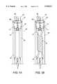
- FIG. 1Ais a perspective view of the graft of the inventive assembly loaded within a sheath introducer
- FIG. 1Bis a perspective view of the graft of the inventive assembly loaded within a sheath introducer in a twisted position;
- FIG. 2Ais a perspective view of the first embodiment of the guide wire of the present invention.
- FIG. 2Bis a second embodiment of the guide wire of the present invention.
- FIG. 2Cis a third embodiment of the guide wire of the present invention.
- FIG. 3Ais a perspective view of the stent of the present invention.
- FIG. 3Bis a perspective view of the stent of the present invention.
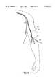
- FIG. 4is a perspective view of the guide wire of the present invention entering the brachial artery
- FIG. 5is a perspective view of the guide wire of the present invention passing between the brachial artery and the femoral artery and exiting the femoral artery;
- FIG. 6Ais a perspective view of the first embodiment of the guide wire attached to the strings of the present invention.
- FIG. 6Bis a perspective view of the second embodiment of the guide wire attached to the strings of the present invention.
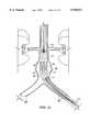
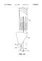
- FIG. 7is a perspective view of the sheath introducer of the present invention and the graft exiting therefrom into the vessel in the region of the aneurysm;
- FIG. 8is a perspective view of the graft of the present invention within the blood vessel and the stent deployment system being moved into position for stent deployment;
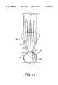
- FIG. 9is a perspective view of a stent being deployed into the graft of the present invention.
- FIG. 10is a perspective view of a stent being deployed into the graft of the present invention.
- FIG. 11is a perspective view of the end cap of the present invention engaged with the graft, strings, and guide wire;
- FIG. 12is a perspective view of the end cap of the present invention engaged with the graft, strings, and guide wire;
- FIG. 13is a perspective view of the end cap of the present invention being removed from the graft;
- FIG. 14is a perspective view of both end caps of the present invention engaged with the both graft ends, strings, and guide wire;
- FIG. 15is a perspective view of both end caps of the present invention being removed from the graft.
- distalrefers to a position relative not to the heart, but to the respective point of entry into the blood vessel.
- proximal and proximateare used in this application. These terms refer to a position relative not to the heart, but to the respective point of entry.
- the end closer to the point of entrywould be the proximate end, and the end farthest from the point of entry would be the distal end.
- the present inventionis comprised of a graft 10, preferably Dacron, of a tubular shape when in an expanded position, and capable of being folded or twisted for loading into a sheath introducer 15.
- Graft 10may have even end portions as shown in FIGS. 1A, 1B, 6A, 6B, 7, 8, 9, and 10 or may have finger-like end portions as shown in the remaining graft drawings.
- Graft 10is further comprised of a first end 16 and a second end 17, each end having a plurality of loops 11, preferably four loops at each side.
- Sheath introducer 15is comprised of a standard material such as plastic or any other substantially flexible material, and contains a distal end 18 and a proximal end (not shown), each end containing an opening 20.
- the present inventionis further comprised of a plurality of strings 12 for temporary attachment to the loops 11 of graft 10.
- strings 12are temporarily attached to loops 11 by passing one end of each string 12 through a loop 11 pulling each end of each string upward and away from loops 11 such that a middle portion 13 of each string 12 is folded over each loop 11.
- the present inventionis further comprised of a guide wire 21 for guiding string ends 14 from a point of entry 30 into the femoral artery 31 to a point of entry 32 in the brachial artery 33.
- Guide wire 21is long enough to extend from point of entry 32 through point of entry 30 with plenty of room on each side for manipulation thereof.
- Guide wire 21is preferably about 0.38 millimeters in diameter and is comprised of a somewhat flexible material such as thin metal or plastic, having an attachment means 22 in a middle portion 23 thereof.
- string ends 14are temporarily affixed to attachment means 22, preferably a ring, for passage from the femoral artery 31 to the brachial artery 33 and out the original point of entry 32.
- Guide wire 21ais an alternative embodiment having attachment means 22a at a distal end 23a thereof.
- Guide wire 24is yet another embodiment and is comprised of a central lumen 25 in fluid communication with a tip balloon 26.
- tip balloon 26is inflated within the second end 17 of graft 10 for temporary attachment and passage from the femoral artery 31 through the point of entry of the brachial artery 32.
- the present inventionis further comprised of a stent delivery system having one or more stents 40, a sheath introducer 45, and balloon catheter 50 and a plunger (not shown).
- a stent 40is comprised of a wire formed in an endless series of straight sections joined by bends; a zig-zag configuration. Stent 40 is further comprised of a plurality of spikes 41, for more securely affixing stent 40 within graft 10 and blood vessel 34. Spikes 41 line the outer surface of stent 40, or more particularly the surface of the stent which is in contact with graft 10 after deployment thereof. Spikes 41 are comprised of a rigid material, such as metal or plastic, and are preferably cone shaped. Furthermore, stent 40 is comprised of a material such as metal which is deformable and capable of returning to its original shape; preferably a shape memory alloy having stress-induced martensite characteristics, such as nitinol. Other materials may also be used such as stainless steel.
- stent 40In operation, stent 40 is deformed either by inducing stress, or in the case of a shape memory alloy not having stress induced martensite characteristics, reducing temperature sufficiently to reach the temperature threshold for the metal's martensitic phase. After deformation of stent 40, it is loaded within sheath introducer 45.
- Sheath introducer 45is of standard material, and is comprised of a distal end and a proximal end (not shown), each end having an opening 48.
- Stent 40may also be passed over a balloon catheter 50 prior to deformation and pre-loading within sheath introducer 45, then loaded with balloon catheter 50.
- Balloon catheter 50is comprised of a catheter 51 having a distal end 52 and a proximal end (not shown).
- catheter 51is comprised of an opening at proximal end (not shown) and an opening into balloon (not shown) which is integral with distal end 52.
- Balloon catheter 50is further comprised of an opening 57 at distal end 52 for passage of catheter 50 over guide wire 21.
- Stent delivery systemis further comprised of standard plunger having a central lumen for passage over catheter 51, and a head for contact with stent 40 at a substantially flat surface of the plunger during stent deployment.
- Headis comprised of a standard substantially rigid material such as plastic or metal located at the forward most part of plunger for pushing force during deployment of stent 40.
- the present inventionis comprised of the following steps. First, strings 12 are temporarily attached to loops 11 of graft 10 by passing ends 14 through loops 11 and folding strings 12 over at middle portion 13 such that the string ends 14 are extending away from graft 10 at the same length. Graft 10 is then loaded into sheath introducer 15 such that string ends 14 are extending outward from each sheath opening 20. For loading of graft 10 into sheath introducer 15, graft 10 may be either twisted or folded so that the entry diameter is small.
- guide wire 21is inserted into the brachial artery 33 at point of entry 32, passed through the descending aorta 34, into the femoral artery 31, and passed out of the vessel at point of entry 30.
- Guide wire 21is then pulled from point of entry 30 until attachment means 22 emerges from the femoral artery 31.
- guide wire 21may be withdrawn from point of entry 32 until attachment means 22 and string ends 14 have been withdrawn completely from vessel 33 and may be manipulated by hand. Guide wire 21 may then be cut at a point distal attachment means 22 so that guide wire 21 may be used to guide stent deployment apparatus to the appropriate point in vessel 34.
- String ends 14may then be used to assist movement of sheath introducer 15 through the vessels to a point within vessel 34 of the aneurysm site using an image amplifier. The position of graft 10 can be verified, and sheath introducer 15 may then be withdrawn from vessel, thus deploying graft 10 within vessel 34. String ends 14 may be used to hold graft 10 in position from both points of entry 32 and 30.
- stent deployment apparatusmay be inserted into brachial artery 33, passed over guide wire 21 until its distal end 46 is within second end 17 of graft 10.
- sheath introducer 45may be withdrawn, while at the same time applying pushing pressure to plunger for deployment of stent 40 within second end 17 of graft 10.
- balloon 56 of balloon catheter 50may be expanded to secure the position of stent 40 within graft 10 and firmly affix spikes 41 within both graft 10 and vessel 34.
- balloon 56 of balloon catheter 50may be deflated and the deployment apparatus removed from the vessel.
- additional stents 40may be deployed in the same manner within graft 10 until graft 10 is sufficiently secured to vessel wall 34. It is generally necessary to deploy at least two stents 40 within graft 10; one on each side of aneurysm 8. It is also valuable to deploy a stent into the middle of graft 10 to support the lumen thereof. If sufficient space is available for affixing stents 40 to graft 10 and vessel wall 34, three or more stents 40 may be used to secure graft 10 thereto. Since guide wire 21 extends from point of entry 30 to point of entry 32, the stent deployment apparatus may be used from either point of entry to deploy stents 40 within graft 10.
- strings 12may be removed by pulling one end 14 of each string until its opposing end is fully withdrawn from the vessel.
- Entry sitesmay then be attended.
- End caps 70may be used in place of sheath introducer 15 for restraining graft 10 during deployment thereof. Prior to insertion of graft 10 into a vessel, graft 10 is twisted and each end is placed within an end cap 70.
- End caps 70are preferably comprised of silicon, and are of a cone shape with an opening 71 at the tip 72 thereof. Opening 71 enables end cap 70 to pass over guide wire 21 through vessels. Opening 71 further enables passage of strings 12 through to attachment means 22.
- end cap 70is comprised of a cap ring 73 to facilitate the temporary attachment of string 12a thereto, just as strings 12 are attached to graft loops 11, and for the removal of end cap 70 after successful positioning of graft 10. After temporary attachment of string 12a to cap ring 73, ends of string 12a are attached to attachment means 22 of guide wire 21, along with string ends 14, for passage through the vessels.
- Graft 10is pulled into the position for deployment and verified with an image amplifier. When positioned, string ends 14a are pulled to remove end caps 70 from each side of graft 10. By continuing to pull on string ends 14a, end caps 70 may be removed from the vessels.
- Stent delivery apparatusmay then be used as described hereinabove to deploy stents 40 within graft 10.
Landscapes
- Health & Medical Sciences (AREA)
- Gastroenterology & Hepatology (AREA)
- Pulmonology (AREA)
- Cardiology (AREA)
- Oral & Maxillofacial Surgery (AREA)
- Transplantation (AREA)
- Engineering & Computer Science (AREA)
- Biomedical Technology (AREA)
- Heart & Thoracic Surgery (AREA)
- Vascular Medicine (AREA)
- Life Sciences & Earth Sciences (AREA)
- Animal Behavior & Ethology (AREA)
- General Health & Medical Sciences (AREA)
- Public Health (AREA)
- Veterinary Medicine (AREA)
- Prostheses (AREA)
- Media Introduction/Drainage Providing Device (AREA)
Abstract
Description
The present invention relates to a blood vessel engrafting system for repairing aneurysms and more particularly to a modular graft system for repairing aortic aneurysms by building a spring loaded graft within a blood vessel via percutaneous entry.
An aortic aneurysm is a very common deteriorating disease typically manifested by a weakening and expansion of the aorta vessel wall at a region between the aorta-renal junction and the aorta-iliac junction. An aneurysm affects the ability of the vessel lumen to conduct fluids, and may at times be life threatening, for instance, when rupture of the vessel wall occurs. A standard treatment for repairing an aneurysm is to surgically remove part or all of the aneurysm and implant a replacement prosthetic section into the vessel. Such surgery, however, is generally postponed until the aneurysm has grown to a diameter greater than five centimeters. With aneurysms over five centimeters in diameter, the risk of complications is greater than the risks inherent in surgical excision and grafting of the aneurysm. Consequently, aortic aneurysms measuring greater than five centimeters in diameter, and those showing rapid increase in size, are generally surgically engrafted as a matter of course, before rupture occurs.
The standard procedure for repairing an aortic aneurysm requires one or two days of preparing the large and small intestines prior to hospitalization. The operation itself generally takes one to three hours to perform, and necessitates several units of blood for transfusion. The patient commonly remains hospitalized for several days following surgery, and requires as much as three months recuperation time before returning to work.
Moreover, there remains a significantly high rate of mortality and morbidity associated with the standard procedure. The mortality rate is as high as 8%, while the morbidity rate includes incident complications such as blood loss, respiratory tract infections, wound infections, graft infections, renal failure, and ischemia of the bleeding intestine. The mortality and morbidity rates for this type of major surgery are also often influenced by the fact that the typical aortic aneurysm patient is elderly and therefor less able to withstand major surgery, including anesthesia.
Other treatments for repairing an aneurysm involve deploying a graft device at the aneurysm site via a catheter traveling through a femoral artery. Conventional tubular aortic replacement sections, however, are generally considerably larger in diameter than the femoral artery and therefore cannot be inserted through the femoral artery lumen to the site of the aneurysm.
Even in the more advanced aortic graft assemblies which enable percutaneous deployment and placement of a spring loaded graft for a non-surgical correction of an aortic aneurysm, the required entry profiles require at least 10-12 FR. This is the case since these graft systems are comprised of graft material, two or more spring stents, a balloon catheter, a sheath introducer, and plunger at a minimum, for deployment of the graft.
Thus, there exists a need for a treatment for aneurysms utilizing a system enabling deployment and placement of an aortic graft which is much smaller thus able to facilitate a much smaller entry profile.
The present invention is comprised of an apparatus for engrafting a blood vessel comprising: a plurality of strings, a tubular graft having a central lumen, wherein the plurality of strings are removably attached to the tubular graft, the graft is removably positioned at least partially within a restraining means, such as a sheath introducer, a guide wire with an attachment means for attachment of the plurality of strings, one or more stents for deployment within the graft, and a means for deploying the stents within the graft.
FIG. 1A is a perspective view of the graft of the inventive assembly loaded within a sheath introducer;
FIG. 1B is a perspective view of the graft of the inventive assembly loaded within a sheath introducer in a twisted position;
FIG. 2A is a perspective view of the first embodiment of the guide wire of the present invention;
FIG. 2B is a second embodiment of the guide wire of the present invention;
FIG. 2C is a third embodiment of the guide wire of the present invention;
FIG. 3A is a perspective view of the stent of the present invention;
FIG. 3B is a perspective view of the stent of the present invention;
FIG. 4 is a perspective view of the guide wire of the present invention entering the brachial artery;
FIG. 5 is a perspective view of the guide wire of the present invention passing between the brachial artery and the femoral artery and exiting the femoral artery;
FIG. 6A is a perspective view of the first embodiment of the guide wire attached to the strings of the present invention;
FIG. 6B is a perspective view of the second embodiment of the guide wire attached to the strings of the present invention;
FIG. 7 is a perspective view of the sheath introducer of the present invention and the graft exiting therefrom into the vessel in the region of the aneurysm;
FIG. 8 is a perspective view of the graft of the present invention within the blood vessel and the stent deployment system being moved into position for stent deployment;
FIG. 9 is a perspective view of a stent being deployed into the graft of the present invention;
FIG. 10 is a perspective view of a stent being deployed into the graft of the present invention;
FIG. 11 is a perspective view of the end cap of the present invention engaged with the graft, strings, and guide wire;
FIG. 12 is a perspective view of the end cap of the present invention engaged with the graft, strings, and guide wire;
FIG. 13 is a perspective view of the end cap of the present invention being removed from the graft;
FIG. 14 is a perspective view of both end caps of the present invention engaged with the both graft ends, strings, and guide wire;
FIG. 15 is a perspective view of both end caps of the present invention being removed from the graft.;
The nature and mode of operation of the present invention will now be more fully described in the following detailed description of a preferred embodiment and alternative embodiments to be read together with the accompanying drawing figures.
The term distal is used in this application. It refers to a position relative not to the heart, but to the respective point of entry into the blood vessel. Furthermore, the terms proximal and proximate are used in this application. These terms refer to a position relative not to the heart, but to the respective point of entry. Thus, with respect to an apparatus, the end closer to the point of entry would be the proximate end, and the end farthest from the point of entry would be the distal end.
As shown in FIG. 1, the present invention is comprised of agraft 10, preferably Dacron, of a tubular shape when in an expanded position, and capable of being folded or twisted for loading into a sheath introducer 15.Graft 10 may have even end portions as shown in FIGS. 1A, 1B, 6A, 6B, 7, 8, 9, and 10 or may have finger-like end portions as shown in the remaining graft drawings. Graft 10 is further comprised of afirst end 16 and asecond end 17, each end having a plurality ofloops 11, preferably four loops at each side.
Sheath introducer 15 is comprised of a standard material such as plastic or any other substantially flexible material, and contains adistal end 18 and a proximal end (not shown), each end containing anopening 20.
The present invention is further comprised of a plurality ofstrings 12 for temporary attachment to theloops 11 ofgraft 10. In particular, prior to loading ofgraft 10 intosheath introducer 15,strings 12 are temporarily attached toloops 11 by passing one end of eachstring 12 through aloop 11 pulling each end of each string upward and away fromloops 11 such that amiddle portion 13 of eachstring 12 is folded over eachloop 11.
As displayed in FIG. 2a, the present invention is further comprised of aguide wire 21 for guiding string ends 14 from a point ofentry 30 into thefemoral artery 31 to a point ofentry 32 in thebrachial artery 33.Guide wire 21 is long enough to extend from point ofentry 32 through point ofentry 30 with plenty of room on each side for manipulation thereof.Guide wire 21 is preferably about 0.38 millimeters in diameter and is comprised of a somewhat flexible material such as thin metal or plastic, having an attachment means 22 in amiddle portion 23 thereof. In operation, string ends 14 are temporarily affixed to attachment means 22, preferably a ring, for passage from thefemoral artery 31 to thebrachial artery 33 and out the original point ofentry 32.
As shown in FIGS. 3A, 3B, 8, 9, 10, the present invention is further comprised of a stent delivery system having one ormore stents 40, asheath introducer 45, andballoon catheter 50 and a plunger (not shown).
Astent 40 is comprised of a wire formed in an endless series of straight sections joined by bends; a zig-zag configuration.Stent 40 is further comprised of a plurality ofspikes 41, for more securely affixingstent 40 withingraft 10 andblood vessel 34.Spikes 41 line the outer surface ofstent 40, or more particularly the surface of the stent which is in contact withgraft 10 after deployment thereof.Spikes 41 are comprised of a rigid material, such as metal or plastic, and are preferably cone shaped. Furthermore,stent 40 is comprised of a material such as metal which is deformable and capable of returning to its original shape; preferably a shape memory alloy having stress-induced martensite characteristics, such as nitinol. Other materials may also be used such as stainless steel.
In operation,stent 40 is deformed either by inducing stress, or in the case of a shape memory alloy not having stress induced martensite characteristics, reducing temperature sufficiently to reach the temperature threshold for the metal's martensitic phase. After deformation ofstent 40, it is loaded withinsheath introducer 45.Sheath introducer 45 is of standard material, and is comprised of a distal end and a proximal end (not shown), each end having anopening 48.
Stent delivery system is further comprised of standard plunger having a central lumen for passage overcatheter 51, and a head for contact withstent 40 at a substantially flat surface of the plunger during stent deployment. Head is comprised of a standard substantially rigid material such as plastic or metal located at the forward most part of plunger for pushing force during deployment ofstent 40.
In operation, the present invention is comprised of the following steps. First, strings 12 are temporarily attached toloops 11 ofgraft 10 by passing ends 14 throughloops 11 andfolding strings 12 over atmiddle portion 13 such that the string ends 14 are extending away fromgraft 10 at the same length.Graft 10 is then loaded intosheath introducer 15 such that string ends 14 are extending outward from eachsheath opening 20. For loading ofgraft 10 intosheath introducer 15,graft 10 may be either twisted or folded so that the entry diameter is small.
Next, as depicted in FIGS. 4 and 5,guide wire 21 is inserted into thebrachial artery 33 at point ofentry 32, passed through the descendingaorta 34, into thefemoral artery 31, and passed out of the vessel at point ofentry 30.Guide wire 21 is then pulled from point ofentry 30 until attachment means 22 emerges from thefemoral artery 31.
String ends 14 atsecond end 17 ofgraft 10 are attached temporarily to attachment means 22 ofguide wire 21.Distal end 27 ofguide wire 21 is passed through opening 20 of sheath introducer and through the central lumen (not shown) ofgraft 10. By virtue of the length ofguide wire 21,distal end 27 will extend throughgraft 10 and exit at theproximal opening 20a ofsheath introducer 15.
After string ends 14 have been temporarily attached to attachment means 22,guide wire 21 may be withdrawn from point ofentry 32 until attachment means 22 and string ends 14 have been withdrawn completely fromvessel 33 and may be manipulated by hand.Guide wire 21 may then be cut at a point distal attachment means 22 so thatguide wire 21 may be used to guide stent deployment apparatus to the appropriate point invessel 34.
String ends 14 may then be used to assist movement ofsheath introducer 15 through the vessels to a point withinvessel 34 of the aneurysm site using an image amplifier. The position ofgraft 10 can be verified, andsheath introducer 15 may then be withdrawn from vessel, thus deployinggraft 10 withinvessel 34. String ends 14 may be used to holdgraft 10 in position from both points ofentry
Withgraft 10 in position, stent deployment apparatus may be inserted intobrachial artery 33, passed overguide wire 21 until its distal end 46 is withinsecond end 17 ofgraft 10. At the appropriate position,sheath introducer 45 may be withdrawn, while at the same time applying pushing pressure to plunger for deployment ofstent 40 withinsecond end 17 ofgraft 10. Afterstent 40 is deployed and expanded withingraft 10,balloon 56 ofballoon catheter 50 may be expanded to secure the position ofstent 40 withingraft 10 and firmly affixspikes 41 within bothgraft 10 andvessel 34. After the position ofstent 40 is secure,balloon 56 ofballoon catheter 50 may be deflated and the deployment apparatus removed from the vessel.
Withguide wire 21 still in position,additional stents 40 may be deployed in the same manner withingraft 10 untilgraft 10 is sufficiently secured tovessel wall 34. It is generally necessary to deploy at least twostents 40 withingraft 10; one on each side ofaneurysm 8. It is also valuable to deploy a stent into the middle ofgraft 10 to support the lumen thereof. If sufficient space is available for affixingstents 40 to graft 10 andvessel wall 34, three ormore stents 40 may be used to securegraft 10 thereto. Sinceguide wire 21 extends from point ofentry 30 to point ofentry 32, the stent deployment apparatus may be used from either point of entry to deploystents 40 withingraft 10.
Afterstents 40 have been deployed withingraft 10, and the stent deployment apparatus has been removed from the vessel, strings 12 may be removed by pulling oneend 14 of each string until its opposing end is fully withdrawn from the vessel.
Entry sites may then be attended.
As shown in FIGS. 11-15, an alternative embodiment provides an even smaller entry profile. End caps 70 may be used in place ofsheath introducer 15 for restraininggraft 10 during deployment thereof. Prior to insertion ofgraft 10 into a vessel,graft 10 is twisted and each end is placed within anend cap 70.
End caps 70 are preferably comprised of silicon, and are of a cone shape with anopening 71 at thetip 72 thereof.Opening 71 enablesend cap 70 to pass overguide wire 21 through vessels.Opening 71 further enables passage ofstrings 12 through to attachment means 22. In addition,end cap 70 is comprised of acap ring 73 to facilitate the temporary attachment ofstring 12a thereto, just asstrings 12 are attached to graftloops 11, and for the removal ofend cap 70 after successful positioning ofgraft 10. After temporary attachment ofstring 12a to capring 73, ends ofstring 12a are attached to attachment means 22 ofguide wire 21, along with string ends 14, for passage through the vessels.
In operation, after graft ends are loaded intoend caps 70, and guidewire 21 is withdrawn sufficiently such that string ends 14 and 14a arc removed from vessel at initial point ofentry 30 ofguide wire 21,graft 10 is inserted into vessel overguide wire 21, and pulled through vessel to the aneurysm site by string ends 14. Care must be taken, however, not to prematurely tug on string ends 14a orend cap 70 will be prematurely removed fromgraft 10.
Stent delivery apparatus may then be used as described hereinabove to deploystents 40 withingraft 10.
Claims (23)
1. An assembly for positioning a graft within a vasculature, which comprises:
a) a guide wire having proximal and distal ends and a first attachment portions wherein the guide wire has a length between the ends sufficient to extend from an entry opening into the vasculature, past a treatment zone and out an exit opening from the vasculature;
b) a graft having a central lumen extending to proximal and distal graft ends; and
c) at least one string extending from each of the proximal and distal graft ends, wherein the at least one string extending from the distal graft end is connectable to the first attachment portion of the guide wire so that when the guide wire extends through the vasculature with the proximal end thereof extending out the entry opening and with the first attachment portion accessible from outside the vasculature adjacent to the entry opening, the at least one string extending from the distal graft end is connectable to the first attachment portion so that the guide wire is manipulatable to move the graft through the vasculature until the at least one string extending from the distal graft end and connected to the first attachment portion of the guide wire extends out the exit opening and the at least one string extending from the proximal graft end extends out the entry opening, and wherein the at least one string extending from the distal draft end is disconnectable from the first attachment portion of the guide wire to remove the guide wire from connection with the graft so that the graft is positionable to span the treatment zone by manipulation of the at least one string connected to each of the proximal and distal graft ends.
2. The assembly of claim 1 further including:
(a) a catheter having proximal and distal ends and an expandable balloon provided at a distal portion of the catheter; and
(b) an expandable stent mounted on the expandable balloon of the catheter, wherein the catheter is movable along the vasculature from either the entry opening or the exit opening to a position at least partially inside the lumen of the graft so that when the expandable balloon is expanded, the expandable stent secures the graft to an inner wall of the vasculature.
3. The assembly of claim 2 wherein the expandable catheter is manipulatable to secure the graft to the inner wall of the vasculature on either side of the treatment zone.
4. The assembly of claim 2 wherein the graft is initially provided in a radially reduced state until such time as the stent secures the graft to the inner wall of the vasculature.
5. The assembly of claim 1 wherein the graft has at least one second attachment portion provided at each of the proximal and distal ends thereof.
6. The assembly of claim 5 wherein at least one string is connectable to the second attachment portion at both the proximal and distal graft ends to provide at least one string extending from the proximal and distal graft ends.
7. The assembly of claim 5 wherein the second attachment portions provided at the proximal and distal graft ends are graft loops-and wherein the at least one string is connectable to the second attachment portion by moving the string through the loop and doubling the string back upon itself.
8. The assembly of claim 1 wherein when the guide wire extends through the vasculature with the proximal end thereof extending out the entry opening and with the first attachment portion accessible from outside the vasculature adjacent to the entry opening, the distal end of the guide wire extends out the exit opening from the vasculature.
9. The assembly of claim 1 further including a restraining device positioned on and about the craft as the graft is positionable to span the treatment zone.
10. The assembly of claim 9 wherein the restraining device is a cylindrically-shaped sheath introducer provided along and about the graft as the graft is positionable to span the treatment zone.
11. The assembly of claim 1 wherein the location of the graft in the vasculature is verifiable by an image amplifier.
12. The assembly of claim 1 further including a restraining device positioned on the at least one string extending from the distal end of the graft to the first attachment portion of the guide wire, wherein the restraining device is an end cap provided adjacent to the distal end of the graft.
13. The assembly of claim 12 wherein the end cap is cone shaped.
14. The assembly of claim 12 wherein the end cap is comprised of a cap ring.
15. The assembly of claim 1 wherein the graft further comprises a plurality of second attachment portions at both the proximal and distal graft ends to provide a plurality of strings extending from both the proximal and distal graft ends.
16. The assembly of claim 11 further comprising a catheter and a plunger movably positioned within a lumen of the catheter for securing the graft to the inner wall of the vasculature with the stent moved into position by the catheter.
17. The assembly of claim 1 further comprising an entry sheath for maintaining the patency of the entry opening and the exit opening.
18. The assembly of claim 1 wherein the guide wire is comprised of a middle portion, and the first attachment portion is comprised of a ring located at the middle portion of the guide wire.
19. The assembly of claim 1 wherein the first attachment portion is a ring positioned at the distal end of the guide wire.
20. The assembly of claim 1 wherein the guide wire is less than 0.38 millimeters in diameter.
21. The assembly of claim 5 wherein the second attachment portions provided at the proximal and distal graft ends are comprised of one or more graft loops.
22. An assembly for repairing an aneurysm within a vasculature, which comprises:
a) a guide wire having proximal and distal ends and a first attachment portion, wherein the guide wire has a length between the ends sufficient to extend from an entry opening into the vasculature, past a treatment zone and out an exit opening from the vasculature;
b) an engrafting device having a central lumen extending to proximal and distal ends thereof; and
c) at least one string extending from each of the proximal and distal ends of the engrafting device, wherein the at least one string extending from the distal end of the engrafting device is connectable to the first attachment portion of the guide wire so that when the guide wire extends through the vasculature with the proximal end thereof extending out the entry opening and with the first attachment portion accessible from outside the vasculature adjacent to the entry opening, the at least one string extending from the distal end of the engrafting device is connectable to the first attachment portion so that the guide wire is manipulable to move the engrafting device through the vasculature until the at least one string extending from the distal end of the engrafting device and connected to the first attachment portion of the guide wire extends out the exit opening and the at least one string extending from the proximal end of the engrafting device extends out the entry opening, and wherein the at least one string extending from the distal end of the engrafting device is disconnectable from the first attachment portion of the guide wire to remove the guide wire from connection with the engrafting device so that the engrafting device is positionable to span the aneurysm by manipulation of the at least one sting connected to each of the proximal and distal ends of the engrafting device.
23. An assembly for positioning a stent within a vasculature, which comprises:
a) a guide wire having proximal and distal ends and a first attachment portion, wherein the guide wire has a length between the ends sufficient to extend from an entry opening into the vasculature, past a treatment zone and out an exit opening from the vasculature;
b) a stent having a central lumen extending to proximal and distal ends thereof; and
c) at least one string extending from each of the proximal and distal ends of the stent, wherein the at least one string extending from the distal end of the stent is connectable to the first attachment portion of the guide wire so that when the guide wire extends through the vasculature with the proximal end thereof extending out the entry opening and with the first attachment portion accessible from outside the vasculature adjacent to the entry opening, the at least one string extending from the distal end of the stent is connectable to the first attachment portion so that the guide wire is manipulable to move the stent through the vasculature until the at least one string extending from the distal end of the stent and connected to the first attachment portion of the guide wire extends out the exit opening and the at least one string extending from the proximal end of the stent extends out the entry opening, and wherein the at least one string extending from the distal end of the stent is disconnectable from the first attachment portion of the guide wire to remove the guide wire from connection with the stent so that the stent is positionable in the vasculature at a desired location by manipulation of the at least one string connected to each of the proximal and distal ends of the stent.
Priority Applications (4)
| Application Number | Priority Date | Filing Date | Title |
|---|---|---|---|
| US08/946,748US5948017A (en) | 1997-10-12 | 1997-10-12 | Modular graft assembly |
| AU10760/99AAU1076099A (en) | 1997-10-12 | 1998-10-09 | Modular graft assembly |
| PCT/US1998/021373WO1999018889A1 (en) | 1997-10-12 | 1998-10-09 | Modular graft assembly |
| US09/307,314US6106549A (en) | 1997-10-12 | 1999-05-07 | Modular graft assembly |
Applications Claiming Priority (1)
| Application Number | Priority Date | Filing Date | Title |
|---|---|---|---|
| US08/946,748US5948017A (en) | 1997-10-12 | 1997-10-12 | Modular graft assembly |
Related Child Applications (1)
| Application Number | Title | Priority Date | Filing Date |
|---|---|---|---|
| US09/307,314DivisionUS6106549A (en) | 1997-10-12 | 1999-05-07 | Modular graft assembly |
Publications (1)
| Publication Number | Publication Date |
|---|---|
| US5948017Atrue US5948017A (en) | 1999-09-07 |
Family
ID=25484936
Family Applications (2)
| Application Number | Title | Priority Date | Filing Date |
|---|---|---|---|
| US08/946,748Expired - Fee RelatedUS5948017A (en) | 1997-10-12 | 1997-10-12 | Modular graft assembly |
| US09/307,314Expired - LifetimeUS6106549A (en) | 1997-10-12 | 1999-05-07 | Modular graft assembly |
Family Applications After (1)
| Application Number | Title | Priority Date | Filing Date |
|---|---|---|---|
| US09/307,314Expired - LifetimeUS6106549A (en) | 1997-10-12 | 1999-05-07 | Modular graft assembly |
Country Status (3)
| Country | Link |
|---|---|
| US (2) | US5948017A (en) |
| AU (1) | AU1076099A (en) |
| WO (1) | WO1999018889A1 (en) |
Cited By (104)
| Publication number | Priority date | Publication date | Assignee | Title |
|---|---|---|---|---|
| WO2002022054A1 (en)* | 2000-09-12 | 2002-03-21 | Gabbay S | Valvular prosthesis and method of using same |
| US6383171B1 (en) | 1999-10-12 | 2002-05-07 | Allan Will | Methods and devices for protecting a passageway in a body when advancing devices through the passageway |
| US6613078B1 (en)* | 2000-08-02 | 2003-09-02 | Hector Daniel Barone | Multi-component endoluminal graft assembly, use thereof and method of implanting |
| US20030199975A1 (en)* | 2000-05-22 | 2003-10-23 | Shlomo Gabbay | Low invasive implantable cardiac prosthesis and method for helping improve operation of a heart valve |
| US6652580B1 (en)* | 1997-01-29 | 2003-11-25 | Endovascular Technologies, Inc. | Modular, staged graft and attachment system for endovascular repair |
| US20040044395A1 (en)* | 2002-09-03 | 2004-03-04 | Scimed Life Systems, Inc. | Elephant trunk thoracic endograft and delivery system |
| US20040068316A1 (en)* | 2002-10-08 | 2004-04-08 | Cook Incorporated | Stent with ring architecture and axially displaced connector segments |
| US6723116B2 (en) | 2002-01-14 | 2004-04-20 | Syde A. Taheri | Exclusion of ascending/descending aorta and/or aortic arch aneurysm |
| US6849087B1 (en) | 1999-10-06 | 2005-02-01 | Timothy A. M. Chuter | Device and method for staged implantation of a graft for vascular repair |
| WO2004105645A3 (en)* | 2003-05-27 | 2005-02-17 | Scimed Life Systems Inc | Staged deployment endograft |
| US20050038508A1 (en)* | 2003-08-13 | 2005-02-17 | Shlomo Gabbay | Implantable cardiac prosthesis for mitigating prolapse of a heart valve |
| US20050119722A1 (en)* | 2003-09-12 | 2005-06-02 | Mikolaj Styrc | Device for treating a blood vessel and a method of preparing the device |
| US6942691B1 (en) | 2000-04-27 | 2005-09-13 | Timothy A. M. Chuter | Modular bifurcated graft for endovascular aneurysm repair |
| US20050276914A1 (en)* | 2004-06-15 | 2005-12-15 | Liu Ming-Dah | Method for manufacturing light guide plate mold cores |
| US20060106415A1 (en)* | 2004-11-12 | 2006-05-18 | Shlomo Gabbay | Apparatus to facilitate implantation |
| US20060142840A1 (en)* | 2004-12-28 | 2006-06-29 | Scimed Life Systems, Inc. | Low profile stent-graft attachment |
| US20060155366A1 (en)* | 2005-01-10 | 2006-07-13 | Laduca Robert | Apparatus and method for deploying an implantable device within the body |
| US20060155363A1 (en)* | 2005-01-10 | 2006-07-13 | Laduca Robert | Apparatus and method for deploying an implantable device within the body |
| US20060167468A1 (en)* | 2004-11-12 | 2006-07-27 | Shlomo Gabbay | Implantation system and method for loading an implanter with a prosthesis |
| US7169175B2 (en) | 2000-05-22 | 2007-01-30 | Orbusneich Medical, Inc. | Self-expanding stent |
| US20070123994A1 (en)* | 2005-11-29 | 2007-05-31 | Ethicon Endo-Surgery, Inc. | Internally Placed Gastric Restriction Device |
| US20070167955A1 (en)* | 2005-01-10 | 2007-07-19 | Duke Fiduciary, Llc | Apparatus and method for deploying an implantable device within the body |
| US20080262596A1 (en)* | 2007-04-17 | 2008-10-23 | Medtronic Vascular, Inc. | Stent Graft Fixation System and Method |
| US7591843B1 (en) | 2002-08-16 | 2009-09-22 | Endovascular Technologies, Inc. | Delivery system for modular endograft with superior attachment system |
| US20090248149A1 (en)* | 2000-09-12 | 2009-10-01 | Shlomo Gabbay | Injectable heart valve prosthesis for low-invasive implantation |
| US7655039B2 (en) | 2003-05-23 | 2010-02-02 | Boston Scientific Scimed, Inc. | Stents with attached looped ends |
| US7766934B2 (en) | 2005-07-12 | 2010-08-03 | Cook Incorporated | Embolic protection device with an integral basket and bag |
| US7771463B2 (en)* | 2003-03-26 | 2010-08-10 | Ton Dai T | Twist-down implant delivery technologies |
| US7771452B2 (en) | 2005-07-12 | 2010-08-10 | Cook Incorporated | Embolic protection device with a filter bag that disengages from a basket |
| US7785361B2 (en) | 2003-03-26 | 2010-08-31 | Julian Nikolchev | Implant delivery technologies |
| US20100249898A1 (en)* | 2009-03-24 | 2010-09-30 | Medtronic Vascular, Inc. | Stent Graft |
| US20100256600A1 (en)* | 2009-04-04 | 2010-10-07 | Ferrera David A | Neurovascular otw pta balloon catheter and delivery system |
| US7850708B2 (en) | 2005-06-20 | 2010-12-14 | Cook Incorporated | Embolic protection device having a reticulated body with staggered struts |
| US7862602B2 (en) | 2005-11-02 | 2011-01-04 | Biosensors International Group, Ltd | Indirect-release electrolytic implant delivery systems |
| US20110178588A1 (en)* | 2008-09-05 | 2011-07-21 | Kenneth Haselby | Apparatus and methods for improved stent deployment |
| US8016869B2 (en) | 2003-03-26 | 2011-09-13 | Biosensors International Group, Ltd. | Guidewire-less stent delivery methods |
| US8109962B2 (en) | 2005-06-20 | 2012-02-07 | Cook Medical Technologies Llc | Retrievable device having a reticulation portion with staggered struts |
| US8152831B2 (en) | 2005-11-17 | 2012-04-10 | Cook Medical Technologies Llc | Foam embolic protection device |
| US8182508B2 (en) | 2005-10-04 | 2012-05-22 | Cook Medical Technologies Llc | Embolic protection device |
| US8187298B2 (en) | 2005-08-04 | 2012-05-29 | Cook Medical Technologies Llc | Embolic protection device having inflatable frame |
| US8216269B2 (en) | 2005-11-02 | 2012-07-10 | Cook Medical Technologies Llc | Embolic protection device having reduced profile |
| US8221446B2 (en) | 2005-03-15 | 2012-07-17 | Cook Medical Technologies | Embolic protection device |
| US8252018B2 (en) | 2007-09-14 | 2012-08-28 | Cook Medical Technologies Llc | Helical embolic protection device |
| US8252017B2 (en) | 2005-10-18 | 2012-08-28 | Cook Medical Technologies Llc | Invertible filter for embolic protection |
| US8337543B2 (en) | 2004-11-05 | 2012-12-25 | Boston Scientific Scimed, Inc. | Prosthesis anchoring and deploying device |
| US20130013057A1 (en)* | 2005-11-14 | 2013-01-10 | Sadra Medical, Inc. | Medical implant deployment tool |
| US8377092B2 (en) | 2005-09-16 | 2013-02-19 | Cook Medical Technologies Llc | Embolic protection device |
| US8388644B2 (en) | 2008-12-29 | 2013-03-05 | Cook Medical Technologies Llc | Embolic protection device and method of use |
| US8419748B2 (en) | 2007-09-14 | 2013-04-16 | Cook Medical Technologies Llc | Helical thrombus removal device |
| US20130103131A1 (en)* | 2010-02-17 | 2013-04-25 | Transcatheter Technologies Gmbh | Implant delivery device adapted to be attached to or interconnected with a catheter, catheter and method |
| US20130150945A1 (en)* | 2011-12-08 | 2013-06-13 | W. L. Gore & Associates, Inc. | Systems and methods for delivery of a medical device |
| US8632562B2 (en) | 2005-10-03 | 2014-01-21 | Cook Medical Technologies Llc | Embolic protection device |
| US8657870B2 (en) | 2009-06-26 | 2014-02-25 | Biosensors International Group, Ltd. | Implant delivery apparatus and methods with electrolytic release |
| US8728148B2 (en) | 2011-11-09 | 2014-05-20 | Cook Medical Technologies Llc | Diameter reducing tie arrangement for endoluminal prosthesis |
| US8795315B2 (en) | 2004-10-06 | 2014-08-05 | Cook Medical Technologies Llc | Emboli capturing device having a coil and method for capturing emboli |
| US20140257453A1 (en)* | 2013-03-11 | 2014-09-11 | Cook Medical Technologies Llc | Systems and methods for maintaining perfusion of branch vessels |
| US8945169B2 (en) | 2005-03-15 | 2015-02-03 | Cook Medical Technologies Llc | Embolic protection device |
| US8945202B2 (en) | 2009-04-28 | 2015-02-03 | Endologix, Inc. | Fenestrated prosthesis |
| US9005279B2 (en) | 2010-11-12 | 2015-04-14 | Shlomo Gabbay | Beating heart buttress and implantation method to prevent prolapse of a heart valve |
| US9034027B2 (en) | 2009-10-13 | 2015-05-19 | Cook Medical Technologies Llc | Paraplegia prevention stent graft |
| US9095456B2 (en) | 2009-10-13 | 2015-08-04 | Cook Medical Technologies Llc | Paraplegia prevention stent graft |
| US9138307B2 (en) | 2007-09-14 | 2015-09-22 | Cook Medical Technologies Llc | Expandable device for treatment of a stricture in a body vessel |
| US9149382B2 (en) | 2011-04-28 | 2015-10-06 | Cook Medical Technologies Llc | Endoluminal prosthesis having multiple branches or fenestrations and methods of deployment |
| US9393055B2 (en) | 2004-10-20 | 2016-07-19 | Vertiflex, Inc. | Spacer insertion instrument |
| US9526642B2 (en) | 2007-02-09 | 2016-12-27 | Taheri Laduca Llc | Vascular implants and methods of fabricating the same |
| US9532812B2 (en) | 2004-10-20 | 2017-01-03 | Vertiflex, Inc. | Interspinous spacer |
| US9572603B2 (en) | 2004-10-20 | 2017-02-21 | Vertiflex, Inc. | Interspinous spacer |
| US9592139B2 (en) | 2013-10-04 | 2017-03-14 | Covidien Lp | Stents twisted prior to deployment and untwisted during deployment |
| US9675303B2 (en) | 2013-03-15 | 2017-06-13 | Vertiflex, Inc. | Visualization systems, instruments and methods of using the same in spinal decompression procedures |
| US9750626B2 (en) | 2012-10-31 | 2017-09-05 | Cook Medical Technologies Llc | Apparatus and methods for improved stent deployment |
| US9861398B2 (en) | 2004-10-20 | 2018-01-09 | Vertiflex, Inc. | Interspinous spacer |
| US9877749B2 (en)* | 2004-10-20 | 2018-01-30 | The Board Of Trustees Of The Leland Stanford Junior University | Systems and methods for posterior dynamic stabilization of the spine |
| US9901434B2 (en) | 2007-02-27 | 2018-02-27 | Cook Medical Technologies Llc | Embolic protection device including a Z-stent waist band |
| US9907639B2 (en) | 2006-09-19 | 2018-03-06 | Cook Medical Technologies Llc | Apparatus and methods for in situ embolic protection |
| US9956011B2 (en) | 2004-10-20 | 2018-05-01 | Vertiflex, Inc. | Interspinous spacer |
| US10039576B2 (en) | 2004-10-20 | 2018-08-07 | The Board Of Trustees Of The Leland Stanford Junior University | Systems and methods for posterior dynamic stabilization of the spine |
| US10058358B2 (en) | 2004-10-20 | 2018-08-28 | The Board Of Trustees Of The Leland Stanford Junior University | Systems and methods for posterior dynamic stabilization of the spine |
| US10080587B2 (en) | 2004-10-20 | 2018-09-25 | Vertiflex, Inc. | Methods for treating a patient's spine |
| US10105249B2 (en) | 2005-01-10 | 2018-10-23 | Taheri Laduca Llc | Apparatus and method for deploying an implantable device within the body |
| US10245166B2 (en) | 2008-02-22 | 2019-04-02 | Endologix, Inc. | Apparatus and method of placement of a graft or graft system |
| US10258389B2 (en) | 2004-10-20 | 2019-04-16 | The Board Of Trustees Of The Leland Stanford Junior University | Systems and methods for posterior dynamic stabilization of the spine |
| US10278744B2 (en) | 2004-10-20 | 2019-05-07 | The Board Of Trustees Of The Leland Stanford Junior University | Systems and methods for posterior dynamic stabilization of the spine |
| US10292738B2 (en) | 2004-10-20 | 2019-05-21 | The Board Of Trustees Of The Leland Stanford Junior University | Systems and methods for stabilizing the motion or adjusting the position of the spine |
| US10524772B2 (en) | 2014-05-07 | 2020-01-07 | Vertiflex, Inc. | Spinal nerve decompression systems, dilation systems, and methods of using the same |
| US10588663B2 (en) | 2006-10-18 | 2020-03-17 | Vertiflex, Inc. | Dilator |
| US10993805B2 (en) | 2008-02-26 | 2021-05-04 | Jenavalve Technology, Inc. | Stent for the positioning and anchoring of a valvular prosthesis in an implantation site in the heart of a patient |
| US11065138B2 (en) | 2016-05-13 | 2021-07-20 | Jenavalve Technology, Inc. | Heart valve prosthesis delivery system and method for delivery of heart valve prosthesis with introducer sheath and loading system |
| US11129737B2 (en) | 2015-06-30 | 2021-09-28 | Endologix Llc | Locking assembly for coupling guidewire to delivery system |
| US11185405B2 (en) | 2013-08-30 | 2021-11-30 | Jenavalve Technology, Inc. | Radially collapsible frame for a prosthetic valve and method for manufacturing such a frame |
| US11197754B2 (en) | 2017-01-27 | 2021-12-14 | Jenavalve Technology, Inc. | Heart valve mimicry |
| US11229461B2 (en) | 2006-10-18 | 2022-01-25 | Vertiflex, Inc. | Interspinous spacer |
| US11337800B2 (en) | 2015-05-01 | 2022-05-24 | Jenavalve Technology, Inc. | Device and method with reduced pacemaker rate in heart valve replacement |
| US11357624B2 (en) | 2007-04-13 | 2022-06-14 | Jenavalve Technology, Inc. | Medical device for treating a heart valve insufficiency |
| US11406518B2 (en) | 2010-11-02 | 2022-08-09 | Endologix Llc | Apparatus and method of placement of a graft or graft system |
| US11439525B2 (en) | 2012-12-27 | 2022-09-13 | Venus Medtech (Hangzhou) Inc. | Implant delivery device adapted to be attached to or interconnected with a catheter, catheter and method |
| US11517431B2 (en) | 2005-01-20 | 2022-12-06 | Jenavalve Technology, Inc. | Catheter system for implantation of prosthetic heart valves |
| US11564794B2 (en) | 2008-02-26 | 2023-01-31 | Jenavalve Technology, Inc. | Stent for the positioning and anchoring of a valvular prosthesis in an implantation site in the heart of a patient |
| US11589981B2 (en) | 2010-05-25 | 2023-02-28 | Jenavalve Technology, Inc. | Prosthetic heart valve and transcatheter delivered endoprosthesis comprising a prosthetic heart valve and a stent |
| US12102542B2 (en) | 2022-02-15 | 2024-10-01 | Boston Scientific Neuromodulation Corporation | Interspinous spacer and methods and systems utilizing the interspinous spacer |
| US12121461B2 (en) | 2015-03-20 | 2024-10-22 | Jenavalve Technology, Inc. | Heart valve prosthesis delivery system and method for delivery of heart valve prosthesis with introducer sheath |
| US12171658B2 (en) | 2022-11-09 | 2024-12-24 | Jenavalve Technology, Inc. | Catheter system for sequential deployment of an expandable implant |
| US12390340B2 (en) | 2023-03-15 | 2025-08-19 | Boston Scientific Neuromodulation Corporation | Interspinous spacer with a range of deployment positions and methods and systems |
| US12414854B2 (en) | 2010-05-20 | 2025-09-16 | Jenavalve Technology, Inc. | Catheter system for introducing an expandable stent into the body of a patient |
| US12433646B2 (en) | 2023-02-21 | 2025-10-07 | Boston Scientific Neuromodulation Corporation | Interspinous spacer with actuator locking arrangements and methods and systems |
Families Citing this family (9)
| Publication number | Priority date | Publication date | Assignee | Title |
|---|---|---|---|---|
| US6113612A (en)* | 1998-11-06 | 2000-09-05 | St. Jude Medical Cardiovascular Group, Inc. | Medical anastomosis apparatus |
| GB0107910D0 (en)* | 2001-03-29 | 2001-05-23 | Isis Innovation | Deployable stent |
| WO2005037361A2 (en)* | 2003-10-22 | 2005-04-28 | Colin Charles Didcott | Dilators and dilator assemblies |
| US7634724B2 (en)* | 2004-08-30 | 2009-12-15 | Microsoft Corporation | Systems and methods for supporting custom graphical representations in reporting software |
| US20070276342A1 (en)* | 2006-03-28 | 2007-11-29 | Bryant Lin | Devices and related methods for treating incontinence |
| WO2008015257A2 (en)* | 2006-08-02 | 2008-02-07 | Syntach Ag | Luminal implant with large expansion ratio |
| US9095466B2 (en) | 2010-11-16 | 2015-08-04 | W. L. Gore & Associates, Inc. | Apposition fiber for use in endoluminal deployment of expandable devices in tortuous anatomies |
| US10765544B2 (en)* | 2014-05-02 | 2020-09-08 | W. L. Gore & Associates, Inc. | Push and pull medical device delivery system |
| FI3941392T3 (en) | 2019-03-20 | 2025-07-28 | Inqb8 Medical Tech Llc | Aortic dissection implant |
Citations (3)
| Publication number | Priority date | Publication date | Assignee | Title |
|---|---|---|---|---|
| US5456694A (en)* | 1994-05-13 | 1995-10-10 | Stentco, Inc. | Device for delivering and deploying intraluminal devices |
| US5800521A (en)* | 1994-11-09 | 1998-09-01 | Endotex Interventional Systems, Inc. | Prosthetic graft and method for aneurysm repair |
| US5843162A (en)* | 1995-05-19 | 1998-12-01 | Inoue; Kanji | Appliance to be implanted, method of collapsing the appliance to be implanted and method of using the appliance to be implanted |
- 1997
- 1997-10-12USUS08/946,748patent/US5948017A/ennot_activeExpired - Fee Related
- 1998
- 1998-10-09AUAU10760/99Apatent/AU1076099A/ennot_activeAbandoned
- 1998-10-09WOPCT/US1998/021373patent/WO1999018889A1/enactiveApplication Filing
- 1999
- 1999-05-07USUS09/307,314patent/US6106549A/ennot_activeExpired - Lifetime
Patent Citations (3)
| Publication number | Priority date | Publication date | Assignee | Title |
|---|---|---|---|---|
| US5456694A (en)* | 1994-05-13 | 1995-10-10 | Stentco, Inc. | Device for delivering and deploying intraluminal devices |
| US5800521A (en)* | 1994-11-09 | 1998-09-01 | Endotex Interventional Systems, Inc. | Prosthetic graft and method for aneurysm repair |
| US5843162A (en)* | 1995-05-19 | 1998-12-01 | Inoue; Kanji | Appliance to be implanted, method of collapsing the appliance to be implanted and method of using the appliance to be implanted |
Cited By (184)
| Publication number | Priority date | Publication date | Assignee | Title |
|---|---|---|---|---|
| US6652580B1 (en)* | 1997-01-29 | 2003-11-25 | Endovascular Technologies, Inc. | Modular, staged graft and attachment system for endovascular repair |
| US8628567B1 (en) | 1997-01-29 | 2014-01-14 | Cook Medical Technologies Llc | Modular, staged graft and attachment system for endovascular repair |
| US20050033400A1 (en)* | 1999-10-06 | 2005-02-10 | Chuter Timothy A.M. | Device and method for staged implantation of a graft for vascular repair |
| US6849087B1 (en) | 1999-10-06 | 2005-02-01 | Timothy A. M. Chuter | Device and method for staged implantation of a graft for vascular repair |
| US6712842B1 (en) | 1999-10-12 | 2004-03-30 | Allan Will | Methods and devices for lining a blood vessel and opening a narrowed region of a blood vessel |
| US6383171B1 (en) | 1999-10-12 | 2002-05-07 | Allan Will | Methods and devices for protecting a passageway in a body when advancing devices through the passageway |
| US6942691B1 (en) | 2000-04-27 | 2005-09-13 | Timothy A. M. Chuter | Modular bifurcated graft for endovascular aneurysm repair |
| US7169175B2 (en) | 2000-05-22 | 2007-01-30 | Orbusneich Medical, Inc. | Self-expanding stent |
| US20030199975A1 (en)* | 2000-05-22 | 2003-10-23 | Shlomo Gabbay | Low invasive implantable cardiac prosthesis and method for helping improve operation of a heart valve |
| US6869444B2 (en) | 2000-05-22 | 2005-03-22 | Shlomo Gabbay | Low invasive implantable cardiac prosthesis and method for helping improve operation of a heart valve |
| US8419786B2 (en) | 2000-05-22 | 2013-04-16 | Orbusneich Medical, Inc. | Self-expanding stent |
| US6613078B1 (en)* | 2000-08-02 | 2003-09-02 | Hector Daniel Barone | Multi-component endoluminal graft assembly, use thereof and method of implanting |
| US7803185B2 (en) | 2000-09-12 | 2010-09-28 | Shlomo Gabbay | Method of implantation of a heart valve prosthesis through a tubular catheter |
| WO2002022054A1 (en)* | 2000-09-12 | 2002-03-21 | Gabbay S | Valvular prosthesis and method of using same |
| US9414912B2 (en) | 2000-09-12 | 2016-08-16 | Edwards Lifesciences Cardiaq Llc | Method for direct implantation of a heart valve prosthesis |
| US20090248149A1 (en)* | 2000-09-12 | 2009-10-01 | Shlomo Gabbay | Injectable heart valve prosthesis for low-invasive implantation |
| US20110238166A1 (en)* | 2000-09-12 | 2011-09-29 | Shlomo Gabbay | Method for direct implantation of a heart valve prosthesis |
| US20050288765A1 (en)* | 2002-01-14 | 2005-12-29 | Taheri Syde S | Exclusion of ascending/descending aorta and/or aortic arch aneurysm |
| US7854758B2 (en)* | 2002-01-14 | 2010-12-21 | Taheri Syde A | Exclusion of ascending/descending aorta and/or aortic arch aneurysm |
| US6723116B2 (en) | 2002-01-14 | 2004-04-20 | Syde A. Taheri | Exclusion of ascending/descending aorta and/or aortic arch aneurysm |
| US7591843B1 (en) | 2002-08-16 | 2009-09-22 | Endovascular Technologies, Inc. | Delivery system for modular endograft with superior attachment system |
| US8518096B2 (en)* | 2002-09-03 | 2013-08-27 | Lifeshield Sciences Llc | Elephant trunk thoracic endograft and delivery system |
| US20040044395A1 (en)* | 2002-09-03 | 2004-03-04 | Scimed Life Systems, Inc. | Elephant trunk thoracic endograft and delivery system |
| US6786922B2 (en)* | 2002-10-08 | 2004-09-07 | Cook Incorporated | Stent with ring architecture and axially displaced connector segments |
| US20040243218A1 (en)* | 2002-10-08 | 2004-12-02 | Schaeffer Darin G. | Stent with ring architecture and axially displaced connector segments |
| US7335228B2 (en) | 2002-10-08 | 2008-02-26 | Cook Incorporated | Stent with ring architecture and axially displaced connector segments |
| US20040068316A1 (en)* | 2002-10-08 | 2004-04-08 | Cook Incorporated | Stent with ring architecture and axially displaced connector segments |
| US8016869B2 (en) | 2003-03-26 | 2011-09-13 | Biosensors International Group, Ltd. | Guidewire-less stent delivery methods |
| US7771463B2 (en)* | 2003-03-26 | 2010-08-10 | Ton Dai T | Twist-down implant delivery technologies |
| US7785361B2 (en) | 2003-03-26 | 2010-08-31 | Julian Nikolchev | Implant delivery technologies |
| US9788979B2 (en) | 2003-05-23 | 2017-10-17 | Boston Scientific Scimed, Inc. | Stents with attached looped ends |
| US8109988B2 (en) | 2003-05-23 | 2012-02-07 | Boston Scientific Scimed, Inc. | Stents with attached looped ends |
| US10426643B2 (en) | 2003-05-23 | 2019-10-01 | Boston Scientific Scimed, Inc. | Stents with attached looped ends |
| US7655039B2 (en) | 2003-05-23 | 2010-02-02 | Boston Scientific Scimed, Inc. | Stents with attached looped ends |
| US20060229703A1 (en)* | 2003-05-27 | 2006-10-12 | Kristoff Nelson | Staged deployment endograft |
| JP2007533359A (en)* | 2003-05-27 | 2007-11-22 | ボストン サイエンティフィック サイムド, インコーポレイテッド | Staged deployment type endograft |
| US7297156B2 (en) | 2003-05-27 | 2007-11-20 | Boston Scientific Corporation | Staged deployment endograft |
| US7101390B2 (en) | 2003-05-27 | 2006-09-05 | Scimed Life Systems, Inc. | Staged deployment endograft |
| WO2004105645A3 (en)* | 2003-05-27 | 2005-02-17 | Scimed Life Systems Inc | Staged deployment endograft |
| US7160322B2 (en) | 2003-08-13 | 2007-01-09 | Shlomo Gabbay | Implantable cardiac prosthesis for mitigating prolapse of a heart valve |
| US20050038508A1 (en)* | 2003-08-13 | 2005-02-17 | Shlomo Gabbay | Implantable cardiac prosthesis for mitigating prolapse of a heart valve |
| US20050119722A1 (en)* | 2003-09-12 | 2005-06-02 | Mikolaj Styrc | Device for treating a blood vessel and a method of preparing the device |
| US9314355B2 (en) | 2003-12-09 | 2016-04-19 | Cormove | Device for treating a blood vessel and a method of preparing the device |
| FR2863160A1 (en)* | 2003-12-09 | 2005-06-10 | Perouse Laboratoires | DEVICE FOR TREATING A BLOOD VESSEL AND METHOD FOR PREPARING THE SAME |
| US20050276914A1 (en)* | 2004-06-15 | 2005-12-15 | Liu Ming-Dah | Method for manufacturing light guide plate mold cores |
| US8795315B2 (en) | 2004-10-06 | 2014-08-05 | Cook Medical Technologies Llc | Emboli capturing device having a coil and method for capturing emboli |
| US10835295B2 (en) | 2004-10-20 | 2020-11-17 | Vertiflex, Inc. | Interspinous spacer |
| US10709481B2 (en) | 2004-10-20 | 2020-07-14 | The Board Of Trustees Of The Leland Stanford Junior University | Systems and methods for posterior dynamic stabilization of the spine |
| US10278744B2 (en) | 2004-10-20 | 2019-05-07 | The Board Of Trustees Of The Leland Stanford Junior University | Systems and methods for posterior dynamic stabilization of the spine |
| US10292738B2 (en) | 2004-10-20 | 2019-05-21 | The Board Of Trustees Of The Leland Stanford Junior University | Systems and methods for stabilizing the motion or adjusting the position of the spine |
| US9877749B2 (en)* | 2004-10-20 | 2018-01-30 | The Board Of Trustees Of The Leland Stanford Junior University | Systems and methods for posterior dynamic stabilization of the spine |
| US9572603B2 (en) | 2004-10-20 | 2017-02-21 | Vertiflex, Inc. | Interspinous spacer |
| US9532812B2 (en) | 2004-10-20 | 2017-01-03 | Vertiflex, Inc. | Interspinous spacer |
| US10039576B2 (en) | 2004-10-20 | 2018-08-07 | The Board Of Trustees Of The Leland Stanford Junior University | Systems and methods for posterior dynamic stabilization of the spine |
| US10058358B2 (en) | 2004-10-20 | 2018-08-28 | The Board Of Trustees Of The Leland Stanford Junior University | Systems and methods for posterior dynamic stabilization of the spine |
| US10080587B2 (en) | 2004-10-20 | 2018-09-25 | Vertiflex, Inc. | Methods for treating a patient's spine |
| US11076893B2 (en) | 2004-10-20 | 2021-08-03 | Vertiflex, Inc. | Methods for treating a patient's spine |
| US10166047B2 (en) | 2004-10-20 | 2019-01-01 | Vertiflex, Inc. | Interspinous spacer |
| US9393055B2 (en) | 2004-10-20 | 2016-07-19 | Vertiflex, Inc. | Spacer insertion instrument |
| US10258389B2 (en) | 2004-10-20 | 2019-04-16 | The Board Of Trustees Of The Leland Stanford Junior University | Systems and methods for posterior dynamic stabilization of the spine |
| US10610267B2 (en) | 2004-10-20 | 2020-04-07 | Vertiflex, Inc. | Spacer insertion instrument |
| US10835297B2 (en) | 2004-10-20 | 2020-11-17 | Vertiflex, Inc. | Interspinous spacer |
| US9956011B2 (en) | 2004-10-20 | 2018-05-01 | Vertiflex, Inc. | Interspinous spacer |
| US9861398B2 (en) | 2004-10-20 | 2018-01-09 | Vertiflex, Inc. | Interspinous spacer |
| US9114039B2 (en) | 2004-11-05 | 2015-08-25 | Boston Scientific Scimed, Inc. | Prosthesis anchoring and deploying device |
| US8337543B2 (en) | 2004-11-05 | 2012-12-25 | Boston Scientific Scimed, Inc. | Prosthesis anchoring and deploying device |
| US20060106415A1 (en)* | 2004-11-12 | 2006-05-18 | Shlomo Gabbay | Apparatus to facilitate implantation |
| US20060167468A1 (en)* | 2004-11-12 | 2006-07-27 | Shlomo Gabbay | Implantation system and method for loading an implanter with a prosthesis |
| US20060142840A1 (en)* | 2004-12-28 | 2006-06-29 | Scimed Life Systems, Inc. | Low profile stent-graft attachment |
| US7641681B2 (en) | 2004-12-28 | 2010-01-05 | Boston Scientific Scimed, Inc. | Low profile stent-graft attachment |
| US10729569B2 (en) | 2005-01-10 | 2020-08-04 | Taheri Laduca Llc | Delivery devices for implanting devices at intersecting lumens |
| US11819431B2 (en) | 2005-01-10 | 2023-11-21 | Taheri Laduca Llc | Apparatus and method for deploying an implantable device within the body |
| US20060155366A1 (en)* | 2005-01-10 | 2006-07-13 | Laduca Robert | Apparatus and method for deploying an implantable device within the body |
| US9204958B2 (en) | 2005-01-10 | 2015-12-08 | Taheri Laduca Llc | Methods for placing a stent in a branched vessel |
| US11510795B2 (en) | 2005-01-10 | 2022-11-29 | Taheri Laduca Llc | Apparatus and method for deploying an implantable device within the body |
| US20060155363A1 (en)* | 2005-01-10 | 2006-07-13 | Laduca Robert | Apparatus and method for deploying an implantable device within the body |
| US20060155358A1 (en)* | 2005-01-10 | 2006-07-13 | Laduca Robert | Methods for placing a stent in a branched vessel |
| US9956102B2 (en) | 2005-01-10 | 2018-05-01 | Taheri Laduca Llc | Apparatus and method for deploying an implantable device within the body |
| US8287583B2 (en) | 2005-01-10 | 2012-10-16 | Taheri Laduca Llc | Apparatus and method for deploying an implantable device within the body |
| US20070167955A1 (en)* | 2005-01-10 | 2007-07-19 | Duke Fiduciary, Llc | Apparatus and method for deploying an implantable device within the body |
| US10166130B2 (en) | 2005-01-10 | 2019-01-01 | Taheri Laduca Llc | Methods for placing a stent in a branched vessel |
| US10105249B2 (en) | 2005-01-10 | 2018-10-23 | Taheri Laduca Llc | Apparatus and method for deploying an implantable device within the body |
| US10179058B2 (en) | 2005-01-10 | 2019-01-15 | Taheri Laduca Llc | Apparatus and method for deploying an implantable device within the body |
| US10806615B2 (en) | 2005-01-10 | 2020-10-20 | Taheri Laduca Llc | Apparatus and method for deploying an implantable device within the body |
| US9220613B2 (en) | 2005-01-10 | 2015-12-29 | Taheri Laduca Llc | Apparatus and method for deploying an implantable device within the body |
| US8128680B2 (en) | 2005-01-10 | 2012-03-06 | Taheri Laduca Llc | Apparatus and method for deploying an implantable device within the body |
| US11517431B2 (en) | 2005-01-20 | 2022-12-06 | Jenavalve Technology, Inc. | Catheter system for implantation of prosthetic heart valves |
| US10653456B2 (en) | 2005-02-04 | 2020-05-19 | Vertiflex, Inc. | Interspinous spacer |
| US8945169B2 (en) | 2005-03-15 | 2015-02-03 | Cook Medical Technologies Llc | Embolic protection device |
| US8221446B2 (en) | 2005-03-15 | 2012-07-17 | Cook Medical Technologies | Embolic protection device |
| US8845677B2 (en) | 2005-06-20 | 2014-09-30 | Cook Medical Technologies Llc | Retrievable device having a reticulation portion with staggered struts |
| US8109962B2 (en) | 2005-06-20 | 2012-02-07 | Cook Medical Technologies Llc | Retrievable device having a reticulation portion with staggered struts |
| US7850708B2 (en) | 2005-06-20 | 2010-12-14 | Cook Incorporated | Embolic protection device having a reticulated body with staggered struts |
| US7771452B2 (en) | 2005-07-12 | 2010-08-10 | Cook Incorporated | Embolic protection device with a filter bag that disengages from a basket |
| US7766934B2 (en) | 2005-07-12 | 2010-08-03 | Cook Incorporated | Embolic protection device with an integral basket and bag |
| US7867247B2 (en) | 2005-07-12 | 2011-01-11 | Cook Incorporated | Methods for embolic protection during treatment of a stenotic lesion in a body vessel |
| US8187298B2 (en) | 2005-08-04 | 2012-05-29 | Cook Medical Technologies Llc | Embolic protection device having inflatable frame |
| US8377092B2 (en) | 2005-09-16 | 2013-02-19 | Cook Medical Technologies Llc | Embolic protection device |
| US8632562B2 (en) | 2005-10-03 | 2014-01-21 | Cook Medical Technologies Llc | Embolic protection device |
| US8182508B2 (en) | 2005-10-04 | 2012-05-22 | Cook Medical Technologies Llc | Embolic protection device |
| US8252017B2 (en) | 2005-10-18 | 2012-08-28 | Cook Medical Technologies Llc | Invertible filter for embolic protection |
| US8900285B2 (en) | 2005-11-02 | 2014-12-02 | Biosensors International Group, Ltd. | Covering electrolytic restraint implant delivery systems |
| US8273116B2 (en) | 2005-11-02 | 2012-09-25 | Biosensors International Group, Ltd. | Indirect-release electrolytic implant delivery systems |
| US8579954B2 (en) | 2005-11-02 | 2013-11-12 | Biosensors International Group, Ltd. | Untwisting restraint implant delivery system |
| US7862602B2 (en) | 2005-11-02 | 2011-01-04 | Biosensors International Group, Ltd | Indirect-release electrolytic implant delivery systems |
| US8216269B2 (en) | 2005-11-02 | 2012-07-10 | Cook Medical Technologies Llc | Embolic protection device having reduced profile |
| US8974509B2 (en) | 2005-11-02 | 2015-03-10 | Biosensors International Group, Ltd. | Pass-through restraint electrolytic implant delivery systems |
| US20130013057A1 (en)* | 2005-11-14 | 2013-01-10 | Sadra Medical, Inc. | Medical implant deployment tool |
| US8152831B2 (en) | 2005-11-17 | 2012-04-10 | Cook Medical Technologies Llc | Foam embolic protection device |
| US20070123994A1 (en)* | 2005-11-29 | 2007-05-31 | Ethicon Endo-Surgery, Inc. | Internally Placed Gastric Restriction Device |
| US9907639B2 (en) | 2006-09-19 | 2018-03-06 | Cook Medical Technologies Llc | Apparatus and methods for in situ embolic protection |
| US11013539B2 (en) | 2006-10-18 | 2021-05-25 | Vertiflex, Inc. | Methods for treating a patient's spine |
| US11229461B2 (en) | 2006-10-18 | 2022-01-25 | Vertiflex, Inc. | Interspinous spacer |
| US12035946B2 (en) | 2006-10-18 | 2024-07-16 | Boston Scientific Neuromodulation Corporation | Interspinous spacer |
| US12226130B2 (en) | 2006-10-18 | 2025-02-18 | Vertiflex, Inc. | Interspinous spacer |
| US12035947B2 (en) | 2006-10-18 | 2024-07-16 | Boston Scientific Neuromodulation Corporation | Devices and methods for treating a patient's spine |
| US11986221B2 (en) | 2006-10-18 | 2024-05-21 | Vertiflex, Inc. | Interspinous spacer |
| US10588663B2 (en) | 2006-10-18 | 2020-03-17 | Vertiflex, Inc. | Dilator |
| US9526642B2 (en) | 2007-02-09 | 2016-12-27 | Taheri Laduca Llc | Vascular implants and methods of fabricating the same |
| US12029667B2 (en) | 2007-02-09 | 2024-07-09 | Taheri Laduca Llc | Vascular implants and methods of fabricating the same |
| US10639176B2 (en) | 2007-02-09 | 2020-05-05 | Taheri Laduca Llc | Vascular implants and methods of fabricating the same |
| US9901434B2 (en) | 2007-02-27 | 2018-02-27 | Cook Medical Technologies Llc | Embolic protection device including a Z-stent waist band |
| US11357624B2 (en) | 2007-04-13 | 2022-06-14 | Jenavalve Technology, Inc. | Medical device for treating a heart valve insufficiency |
| US7806917B2 (en) | 2007-04-17 | 2010-10-05 | Medtronic Vascular, Inc. | Stent graft fixation system and method |
| US20080262596A1 (en)* | 2007-04-17 | 2008-10-23 | Medtronic Vascular, Inc. | Stent Graft Fixation System and Method |
| US9138307B2 (en) | 2007-09-14 | 2015-09-22 | Cook Medical Technologies Llc | Expandable device for treatment of a stricture in a body vessel |
| US8252018B2 (en) | 2007-09-14 | 2012-08-28 | Cook Medical Technologies Llc | Helical embolic protection device |
| US9398946B2 (en) | 2007-09-14 | 2016-07-26 | Cook Medical Technologies Llc | Expandable device for treatment of a stricture in a body vessel |
| US8419748B2 (en) | 2007-09-14 | 2013-04-16 | Cook Medical Technologies Llc | Helical thrombus removal device |
| US10245166B2 (en) | 2008-02-22 | 2019-04-02 | Endologix, Inc. | Apparatus and method of placement of a graft or graft system |
| US11564794B2 (en) | 2008-02-26 | 2023-01-31 | Jenavalve Technology, Inc. | Stent for the positioning and anchoring of a valvular prosthesis in an implantation site in the heart of a patient |
| US12232957B2 (en) | 2008-02-26 | 2025-02-25 | Jenavalve Technology, Inc. | Stent for the positioning and anchoring of a valvular prosthesis in an implantation site in the heart of a patient |
| US10993805B2 (en) | 2008-02-26 | 2021-05-04 | Jenavalve Technology, Inc. | Stent for the positioning and anchoring of a valvular prosthesis in an implantation site in the heart of a patient |
| US11154398B2 (en) | 2008-02-26 | 2021-10-26 | JenaValve Technology. Inc. | Stent for the positioning and anchoring of a valvular prosthesis in an implantation site in the heart of a patient |
| US20110178588A1 (en)* | 2008-09-05 | 2011-07-21 | Kenneth Haselby | Apparatus and methods for improved stent deployment |
| US9192497B2 (en)* | 2008-09-05 | 2015-11-24 | Cook Medical Technologies Llc | Apparatus and methods for improved stent deployment |
| US8388644B2 (en) | 2008-12-29 | 2013-03-05 | Cook Medical Technologies Llc | Embolic protection device and method of use |
| US8657849B2 (en) | 2008-12-29 | 2014-02-25 | Cook Medical Technologies Llc | Embolic protection device and method of use |
| US20100249898A1 (en)* | 2009-03-24 | 2010-09-30 | Medtronic Vascular, Inc. | Stent Graft |
| US20100256600A1 (en)* | 2009-04-04 | 2010-10-07 | Ferrera David A | Neurovascular otw pta balloon catheter and delivery system |
| US10603196B2 (en) | 2009-04-28 | 2020-03-31 | Endologix, Inc. | Fenestrated prosthesis |
| US8945202B2 (en) | 2009-04-28 | 2015-02-03 | Endologix, Inc. | Fenestrated prosthesis |
| US8657870B2 (en) | 2009-06-26 | 2014-02-25 | Biosensors International Group, Ltd. | Implant delivery apparatus and methods with electrolytic release |
| US9095456B2 (en) | 2009-10-13 | 2015-08-04 | Cook Medical Technologies Llc | Paraplegia prevention stent graft |
| US9034027B2 (en) | 2009-10-13 | 2015-05-19 | Cook Medical Technologies Llc | Paraplegia prevention stent graft |
| US9724187B2 (en) | 2009-10-13 | 2017-08-08 | Cook Medical Technologies Llc | Paraplegia prevention stent graft |
| US10390981B2 (en)* | 2010-02-17 | 2019-08-27 | Venus Medtech (Hangzhou) Inc. | Implant delivery device adapted to be attached to or interconnected with a catheter, catheter and method |
| US20130103131A1 (en)* | 2010-02-17 | 2013-04-25 | Transcatheter Technologies Gmbh | Implant delivery device adapted to be attached to or interconnected with a catheter, catheter and method |
| US12414854B2 (en) | 2010-05-20 | 2025-09-16 | Jenavalve Technology, Inc. | Catheter system for introducing an expandable stent into the body of a patient |
| US11589981B2 (en) | 2010-05-25 | 2023-02-28 | Jenavalve Technology, Inc. | Prosthetic heart valve and transcatheter delivered endoprosthesis comprising a prosthetic heart valve and a stent |
| US11406518B2 (en) | 2010-11-02 | 2022-08-09 | Endologix Llc | Apparatus and method of placement of a graft or graft system |
| US9005279B2 (en) | 2010-11-12 | 2015-04-14 | Shlomo Gabbay | Beating heart buttress and implantation method to prevent prolapse of a heart valve |
| US11607304B2 (en) | 2011-04-28 | 2023-03-21 | Cook Medical Technologies Llc | Endoluminal prosthesis having multiple branches or fenestrations and methods of deployment |
| US9149382B2 (en) | 2011-04-28 | 2015-10-06 | Cook Medical Technologies Llc | Endoluminal prosthesis having multiple branches or fenestrations and methods of deployment |
| US12133793B2 (en) | 2011-04-28 | 2024-11-05 | Cook Medical Technologies Llc | Endoluminal prosthesis having multiple branches or fenestrations and methods of deployment |
| US10722342B2 (en) | 2011-04-28 | 2020-07-28 | The Cleveland Clinic Foundation | Endoluminal prosthesis having multiple branches or fenestrations and methods of deployment |
| US9883938B2 (en) | 2011-04-28 | 2018-02-06 | Cook Medical Technologies Llc | Endoluminal prosthesis having multiple branches or fenestrations and methods of deployment |
| US8728148B2 (en) | 2011-11-09 | 2014-05-20 | Cook Medical Technologies Llc | Diameter reducing tie arrangement for endoluminal prosthesis |
| US20130150945A1 (en)* | 2011-12-08 | 2013-06-13 | W. L. Gore & Associates, Inc. | Systems and methods for delivery of a medical device |
| US9364359B2 (en)* | 2011-12-08 | 2016-06-14 | W. L. Gore & Associates, Inc. | Systems and methods for delivery of a medical device |
| US9750626B2 (en) | 2012-10-31 | 2017-09-05 | Cook Medical Technologies Llc | Apparatus and methods for improved stent deployment |
| US11439525B2 (en) | 2012-12-27 | 2022-09-13 | Venus Medtech (Hangzhou) Inc. | Implant delivery device adapted to be attached to or interconnected with a catheter, catheter and method |
| US9808364B2 (en)* | 2013-03-11 | 2017-11-07 | Cook Medical Technologies Llc | Systems and methods for maintaining perfusion of branch vessels |
| US20140257453A1 (en)* | 2013-03-11 | 2014-09-11 | Cook Medical Technologies Llc | Systems and methods for maintaining perfusion of branch vessels |
| US9675303B2 (en) | 2013-03-15 | 2017-06-13 | Vertiflex, Inc. | Visualization systems, instruments and methods of using the same in spinal decompression procedures |
| US11185405B2 (en) | 2013-08-30 | 2021-11-30 | Jenavalve Technology, Inc. | Radially collapsible frame for a prosthetic valve and method for manufacturing such a frame |
| US12318281B2 (en) | 2013-08-30 | 2025-06-03 | Jenavalve Technology, Inc. | Radially collapsible frame for a prosthetic valve and method for manufacturing such a frame |
| US9592139B2 (en) | 2013-10-04 | 2017-03-14 | Covidien Lp | Stents twisted prior to deployment and untwisted during deployment |
| US10524945B2 (en) | 2013-10-04 | 2020-01-07 | Covidien Lp | Stents twisted prior to deployment and untwisted during deployment |
| US12035884B2 (en) | 2014-05-07 | 2024-07-16 | Boston Scientific Neuromodulation Corporation | Spinal nerve decompression systems, dilation systems, and methods of using the same |
| US10524772B2 (en) | 2014-05-07 | 2020-01-07 | Vertiflex, Inc. | Spinal nerve decompression systems, dilation systems, and methods of using the same |
| US11357489B2 (en) | 2014-05-07 | 2022-06-14 | Vertiflex, Inc. | Spinal nerve decompression systems, dilation systems, and methods of using the same |
| US12121461B2 (en) | 2015-03-20 | 2024-10-22 | Jenavalve Technology, Inc. | Heart valve prosthesis delivery system and method for delivery of heart valve prosthesis with introducer sheath |
| US11337800B2 (en) | 2015-05-01 | 2022-05-24 | Jenavalve Technology, Inc. | Device and method with reduced pacemaker rate in heart valve replacement |
| US12343255B2 (en) | 2015-05-01 | 2025-07-01 | Jenavalve Technology, Inc. | Device and method with reduced pacemaker rate in heart valve replacement |
| US11129737B2 (en) | 2015-06-30 | 2021-09-28 | Endologix Llc | Locking assembly for coupling guidewire to delivery system |
| US12186215B2 (en) | 2015-06-30 | 2025-01-07 | Endologix Llc | Locking assembly for coupling guidewire to delivery system |
| US11065138B2 (en) | 2016-05-13 | 2021-07-20 | Jenavalve Technology, Inc. | Heart valve prosthesis delivery system and method for delivery of heart valve prosthesis with introducer sheath and loading system |
| US11197754B2 (en) | 2017-01-27 | 2021-12-14 | Jenavalve Technology, Inc. | Heart valve mimicry |
| US12433745B2 (en) | 2017-01-27 | 2025-10-07 | Jenavalve Technology, Inc. | Heart valve mimicry |
| US12102542B2 (en) | 2022-02-15 | 2024-10-01 | Boston Scientific Neuromodulation Corporation | Interspinous spacer and methods and systems utilizing the interspinous spacer |
| US12171658B2 (en) | 2022-11-09 | 2024-12-24 | Jenavalve Technology, Inc. | Catheter system for sequential deployment of an expandable implant |
| US12433646B2 (en) | 2023-02-21 | 2025-10-07 | Boston Scientific Neuromodulation Corporation | Interspinous spacer with actuator locking arrangements and methods and systems |
| US12390340B2 (en) | 2023-03-15 | 2025-08-19 | Boston Scientific Neuromodulation Corporation | Interspinous spacer with a range of deployment positions and methods and systems |
Also Published As
| Publication number | Publication date |
|---|---|
| US6106549A (en) | 2000-08-22 |
| AU1076099A (en) | 1999-05-03 |
| WO1999018889A1 (en) | 1999-04-22 |
Similar Documents
| Publication | Publication Date | Title |
|---|---|---|
| US5948017A (en) | Modular graft assembly | |
| EP1796583B1 (en) | Device for delivering an endovascular stent-graft having a logitudinally unsupported portion | |
| US6099548A (en) | Apparatus and method for deploying an aortic arch graft | |
| US8523931B2 (en) | Dual concentric guidewire and methods of bifurcated graft deployment | |
| US7854758B2 (en) | Exclusion of ascending/descending aorta and/or aortic arch aneurysm | |
| EP2268227B1 (en) | Bifurcated graft deployment systems | |
| EP2083747B1 (en) | System for positioning a stent graft | |
| US6689157B2 (en) | Dual wire placement catheter | |
| US8568466B2 (en) | Graft deployment system | |
| US8147535B2 (en) | Bifurcation graft deployment catheter | |
| EP1117458B1 (en) | Guidewire capture device | |
| US20100179636A1 (en) | Graft deployment system | |
| US20030135269A1 (en) | Laparoscopic-assisted endovascular/endoluminal graft placement | |
| EP1572034B1 (en) | Graft deployment system |
Legal Events
| Date | Code | Title | Description |
|---|---|---|---|
| FPAY | Fee payment | Year of fee payment:4 | |
| REMI | Maintenance fee reminder mailed | ||
| AS | Assignment | Owner name:TAHERI ENTERPRISES, LLC, MICHIGAN Free format text:ASSIGNMENT OF ASSIGNORS INTEREST;ASSIGNOR:TAHERI, SYDE;REEL/FRAME:015756/0864 Effective date:20040823 | |
| FPAY | Fee payment | Year of fee payment:8 | |
| REMI | Maintenance fee reminder mailed | ||
| LAPS | Lapse for failure to pay maintenance fees | ||
| STCH | Information on status: patent discontinuation | Free format text:PATENT EXPIRED DUE TO NONPAYMENT OF MAINTENANCE FEES UNDER 37 CFR 1.362 | |
| FP | Lapsed due to failure to pay maintenance fee | Effective date:20110907 |