US5948002A - Apparatus and method for use in positioning a suture anchor - Google Patents
Apparatus and method for use in positioning a suture anchorDownload PDFInfo
- Publication number
- US5948002A US5948002AUS09/022,351US2235198AUS5948002AUS 5948002 AUS5948002 AUS 5948002AUS 2235198 AUS2235198 AUS 2235198AUS 5948002 AUS5948002 AUS 5948002A
- Authority
- US
- United States
- Prior art keywords
- suture anchor
- tubular member
- end portion
- passage
- tubular
- Prior art date
- Legal status (The legal status is an assumption and is not a legal conclusion. Google has not performed a legal analysis and makes no representation as to the accuracy of the status listed.)
- Expired - Lifetime
Links
- 238000000034methodMethods0.000titleclaimsdescription98
- 238000000926separation methodMethods0.000claimsabstractdescription10
- 230000015572biosynthetic processEffects0.000claimsabstractdescription5
- 230000000694effectsEffects0.000claimsdescription11
- 230000001154acute effectEffects0.000claimsdescription3
- 230000000903blocking effectEffects0.000claimsdescription2
- 230000000979retarding effectEffects0.000claims4
- 238000012800visualizationMethods0.000abstractdescription3
- 210000001519tissueAnatomy0.000description159
- 238000010276constructionMethods0.000description41
- 210000000988bone and boneAnatomy0.000description38
- 239000000463materialSubstances0.000description20
- 239000002184metalSubstances0.000description11
- 238000003780insertionMethods0.000description10
- 230000037431insertionEffects0.000description10
- 239000007787solidSubstances0.000description9
- 230000008859changeEffects0.000description7
- 229910001220stainless steelInorganic materials0.000description5
- 239000010935stainless steelSubstances0.000description5
- -1specificallySubstances0.000description4
- 230000007423decreaseEffects0.000description3
- 239000002390adhesive tapeSubstances0.000description2
- 238000013459approachMethods0.000description2
- 230000004323axial lengthEffects0.000description2
- 239000013013elastic materialSubstances0.000description2
- 229920000747poly(lactic acid)Polymers0.000description2
- 102000008186CollagenHuman genes0.000description1
- 108010035532CollagenProteins0.000description1
- 239000004698PolyethyleneSubstances0.000description1
- 229920000331PolyhydroxybutyratePolymers0.000description1
- 239000002253acidSubstances0.000description1
- 230000009471actionEffects0.000description1
- 238000004873anchoringMethods0.000description1
- 230000008901benefitEffects0.000description1
- 239000000560biocompatible materialSubstances0.000description1
- 210000001124body fluidAnatomy0.000description1
- 239000010839body fluidSubstances0.000description1
- 229920002678cellulosePolymers0.000description1
- 239000001913celluloseSubstances0.000description1
- 239000000919ceramicSubstances0.000description1
- 229920001436collagenPolymers0.000description1
- 230000001054cortical effectEffects0.000description1
- 230000003247decreasing effectEffects0.000description1
- 230000005484gravityEffects0.000description1
- 230000007246mechanismEffects0.000description1
- 210000000056organAnatomy0.000description1
- XYJRXVWERLGGKC-UHFFFAOYSA-Dpentacalcium;hydroxide;triphosphateChemical class[OH-].[Ca+2].[Ca+2].[Ca+2].[Ca+2].[Ca+2].[O-]P([O-])([O-])=O.[O-]P([O-])([O-])=O.[O-]P([O-])([O-])=OXYJRXVWERLGGKC-UHFFFAOYSA-D0.000description1
- 239000005015poly(hydroxybutyrate)Substances0.000description1
- 229920000573polyethylenePolymers0.000description1
- 230000009467reductionEffects0.000description1
- 230000000717retained effectEffects0.000description1
- 210000004872soft tissueAnatomy0.000description1
- 238000011144upstream manufacturingMethods0.000description1
- 210000001835visceraAnatomy0.000description1
Images


Classifications
- A—HUMAN NECESSITIES
- A61—MEDICAL OR VETERINARY SCIENCE; HYGIENE
- A61B—DIAGNOSIS; SURGERY; IDENTIFICATION
- A61B17/00—Surgical instruments, devices or methods
- A61B17/34—Trocars; Puncturing needles
- A61B17/3468—Trocars; Puncturing needles for implanting or removing devices, e.g. prostheses, implants, seeds, wires
- A—HUMAN NECESSITIES
- A61—MEDICAL OR VETERINARY SCIENCE; HYGIENE
- A61B—DIAGNOSIS; SURGERY; IDENTIFICATION
- A61B17/00—Surgical instruments, devices or methods
- A61B17/04—Surgical instruments, devices or methods for suturing wounds; Holders or packages for needles or suture materials
- A61B17/0401—Suture anchors, buttons or pledgets, i.e. means for attaching sutures to bone, cartilage or soft tissue; Instruments for applying or removing suture anchors
- A—HUMAN NECESSITIES
- A61—MEDICAL OR VETERINARY SCIENCE; HYGIENE
- A61B—DIAGNOSIS; SURGERY; IDENTIFICATION
- A61B17/00—Surgical instruments, devices or methods
- A61B17/16—Instruments for performing osteoclasis; Drills or chisels for bones; Trepans
- A61B17/17—Guides or aligning means for drills, mills, pins or wires
- A61B17/1796—Guides or aligning means for drills, mills, pins or wires for holes for sutures or flexible wires
- A—HUMAN NECESSITIES
- A61—MEDICAL OR VETERINARY SCIENCE; HYGIENE
- A61B—DIAGNOSIS; SURGERY; IDENTIFICATION
- A61B17/00—Surgical instruments, devices or methods
- A61B2017/0042—Surgical instruments, devices or methods with special provisions for gripping
- A61B2017/00455—Orientation indicators, e.g. recess on the handle
- A—HUMAN NECESSITIES
- A61—MEDICAL OR VETERINARY SCIENCE; HYGIENE
- A61B—DIAGNOSIS; SURGERY; IDENTIFICATION
- A61B17/00—Surgical instruments, devices or methods
- A61B17/04—Surgical instruments, devices or methods for suturing wounds; Holders or packages for needles or suture materials
- A61B17/0401—Suture anchors, buttons or pledgets, i.e. means for attaching sutures to bone, cartilage or soft tissue; Instruments for applying or removing suture anchors
- A61B2017/0409—Instruments for applying suture anchors
- A—HUMAN NECESSITIES
- A61—MEDICAL OR VETERINARY SCIENCE; HYGIENE
- A61B—DIAGNOSIS; SURGERY; IDENTIFICATION
- A61B17/00—Surgical instruments, devices or methods
- A61B17/04—Surgical instruments, devices or methods for suturing wounds; Holders or packages for needles or suture materials
- A61B17/0401—Suture anchors, buttons or pledgets, i.e. means for attaching sutures to bone, cartilage or soft tissue; Instruments for applying or removing suture anchors
- A61B2017/0417—T-fasteners
- A—HUMAN NECESSITIES
- A61—MEDICAL OR VETERINARY SCIENCE; HYGIENE
- A61B—DIAGNOSIS; SURGERY; IDENTIFICATION
- A61B17/00—Surgical instruments, devices or methods
- A61B17/04—Surgical instruments, devices or methods for suturing wounds; Holders or packages for needles or suture materials
- A61B2017/0496—Surgical instruments, devices or methods for suturing wounds; Holders or packages for needles or suture materials for tensioning sutures
- A—HUMAN NECESSITIES
- A61—MEDICAL OR VETERINARY SCIENCE; HYGIENE
- A61B—DIAGNOSIS; SURGERY; IDENTIFICATION
- A61B90/00—Instruments, implements or accessories specially adapted for surgery or diagnosis and not covered by any of the groups A61B1/00 - A61B50/00, e.g. for luxation treatment or for protecting wound edges
- A61B90/03—Automatic limiting or abutting means, e.g. for safety
- A61B2090/033—Abutting means, stops, e.g. abutting on tissue or skin
- A61B2090/034—Abutting means, stops, e.g. abutting on tissue or skin abutting on parts of the device itself
- A—HUMAN NECESSITIES
- A61—MEDICAL OR VETERINARY SCIENCE; HYGIENE
- A61B—DIAGNOSIS; SURGERY; IDENTIFICATION
- A61B90/00—Instruments, implements or accessories specially adapted for surgery or diagnosis and not covered by any of the groups A61B1/00 - A61B50/00, e.g. for luxation treatment or for protecting wound edges
- A61B90/06—Measuring instruments not otherwise provided for
- A61B2090/062—Measuring instruments not otherwise provided for penetration depth
Definitions
- the present inventionrelates to a new and improved method and apparatus for use in positioning a suture anchor relative to the apparatus and/or relative to body tissue.
- a known apparatus for use in positioning a suture anchor relative to body tissueincludes a tubular member in which a suture anchor and a pusher member are received. During assembly of the apparatus it is necessary to position the suture anchor and a suture relative to the tubular member. Difficulty may be encountered in positioning the suture relative to the tubular member. In addition, difficulty may be encountered in retaining the suture anchor in a desired position relative to the tubular member.
- the present inventionrelates to a new and improved method and apparatus for use in positioning a suture anchor during assembly of the apparatus.
- the present inventionalso relates to a new and improved method and apparatus for use in positioning a suture anchor relative to body tissue.
- the apparatusincludes a tubular outer member and an inner member which is received in a passage in the tubular outer member.
- a slotmay extend between openings at opposite ends of the tubular outer member.
- the slotreceives a suture connected with a suture anchor and facilitates positioning of the suture during assembly of the apparatus. During positioning of the suture anchor relative to body tissue, the slot facilitates visualization of the suture anchor by a surgeon. Once the suture anchor has been positioned relative to body tissue, the slot facilitates disengagement of the suture from the apparatus. Stop surfaces may be provided in association with the inner and outer members to facilitate moving the suture anchor to a desired position relative to the inner and outer members during relative movement between the inner and outer members.
- the apparatusmay include a retainer which holds a suture anchor in a desired position relative to the apparatus during assembly of the apparatus and during positioning of the suture anchor relative to body tissue.
- the retaineris deflected under the influence of force applied against the retainer by the suture anchor to enable the retainer to grip the suture anchor and hold the suture anchor in the desired position.
- the retainermay engage a recess in the suture anchor.
- the recessmay be formed by a passage in the suture anchor through which the suture extends.
- the recessmay be formed in an outer side surface of the suture anchor.
- the tubular outer membermay be utilized as a guide for a drill which forms an opening in the body tissue. After the opening has been formed in the body tissue, the drill is removed from the tubular outer member and the suture anchor is moved along the tubular outer member into the body tissue.
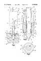
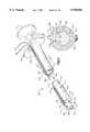
- FIG. 1is a simplified schematic illustration of the manner in which one apparatus constructed in accordance with the present invention may be utilized to position the suture anchor in body tissue;
- FIG. 2is an enlarged fragmentary sectional view further illustrating the relationship between the suture anchor, a tubular outer member and an inner member of the apparatus of FIG. 1;
- FIG. 3is a sectional view, taken generally along the line 3--3 of FIG. 2, illustrating the relationship between the tubular outer member and inner member of the apparatus;
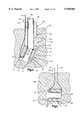
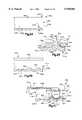
- FIG. 4is a schematic illustration depicting the manner in which the orientation of a suture anchor may be changed in the body tissue of FIG. 1;
- FIG. 5is a schematic illustration depicting the suture anchor of FIG. 4 after the suture anchor has been moved to a desired orientation in the body tissue;
- FIG. 6is a schematic illustration, generally similar to FIG. 1, illustrating a second embodiment of the apparatus
- FIG. 7is an enlarged fragmentary sectional view illustrating the relationship between a suture anchor and a one-piece shaft of the apparatus of FIG. 6;
- FIG. 8is a sectional view, taken generally along the line 8--8 of FIG. 7 further illustrating the construction of the shaft of the apparatus;
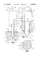
- FIG. 9is a schematic illustration depicting the manner in which the orientation of the suture anchor may be changed in body tissue with the apparatus of FIGS. 6-8;
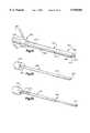
- FIG. 10is a schematic illustration depicting the relationship between an end portion of a shaft of a third embodiment of the apparatus and a suture anchor;
- FIG. 11is a fragmentary schematic pictorial illustration of one embodiment of another apparatus which is constructed and assembled in accordance with the present invention and is utilized to position a suture anchor relative to body tissue;
- FIG. 12is a sectional view, taken generally along the line 12--12 of FIG. 11, illustrating the relationship between a tubular outer member and an inner member of the apparatus of FIG. 11;
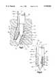
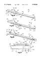
- FIG. 13is a schematic illustration depicting the manner in which the apparatus of FIG. 11 is utilized to initially position a suture anchor relative to body tissue;
- FIG. 14is a schematic illustration, generally similar to FIG. 13, illustrating the manner in which the apparatus of FIG. 11 is utilized to move the suture anchor into an opening formed in the body tissue;
- FIG. 15is a schematic illustration depicting the manner in which the apparatus of FIG. 11 is utilized to change the orientation of the suture anchor relative to body tissue;
- FIG. 16is a fragmentary schematic pictorial illustration of a portion of an alternative embodiment of the apparatus of FIG. 11;
- FIG. 17is a sectional view, taken generally along the line 17--17 of FIG. 16, illustrating the manner in which a rotatable sleeve retains portion of a suture in a slot in a tubular outer member of the apparatus of FIG. 16;
- FIG. 18is a sectional view, generally similar to FIG. 16, illustrating the manner in which the sleeve is positioned relative to the tubular outer member to enable the suture to be moved out of the slot in the tubular outer member;
- FIG. 19is a fragmentary schematic illustration of an end portion of a tubular outer member of another embodiment of the apparatus illustrated in FIG. 11 and in which the end portion of the tubular outer member is contracted;
- FIG. 20is a fragmentary schematic illustration, generally similar to FIG. 19, illustrating the relationship between the end portion of the tubular outer member, a suture anchor, and an inner member after the end portion of the tubular outer member has been expanded and is effective to grip an outer side surface of the suture anchor;
- FIG. 21is a schematic sectional view depicting the manner in which a leading end of the suture anchor of FIG. 20 is moved into engagement with the contracted end portion of the tubular outer member of FIG. 19;
- FIG. 22is a schematic sectional view, generally similar to FIG. 21, depicting the manner in which the end portion of the tubular outer member of FIG. 19 is resiliently deflected outward by the suture anchor as the suture anchor moves to the position shown in FIG. 20;
- FIG. 23is a schematic illustration, generally similar to FIG. 22, of a another embodiment of the invention, having the same general construction as the embodiment of FIG. 11, and illustrating the manner in which a projection on the end portion of a tubular outer member engages a recess in a suture anchor;
- FIG. 24is a schematic sectional view, generally similar to FIGS. 21 and 22, of a projection on an end portion of a tubular outer member of an apparatus which forms another embodiment of the invention having the same general construction as the embodiment of FIG. 11;
- FIG. 25is a schematic sectional view illustrating the manner in which the projection on the end portion of the tubular outer member of FIG. 24 engages an end portion of a passage in a suture anchor through which a suture extends;
- FIG. 26is a schematic sectional view, generally similar to FIG. 24, of another embodiment of the invention, having the same general construction as the embodiment of FIG. 11, and illustrating a pair of projections on an end portion of a tubular outer member;
- FIG. 27is a schematic sectional view illustrating the manner in which the projections of FIG. 26 engage the end portions of a pair of passages in a suture anchor through which a suture extends;
- FIG. 28is a schematic sectional view of another embodiment of the invention, having the same general construction as the embodiment of FIG. 11, and illustrating the manner in which a spring on a tubular outer member engages an end portion of a passage in a suture anchor;
- FIG. 29is a schematic sectional view of another embodiment of the invention, having the same general construction as the embodiment of FIG. 1 and illustrating the manner in which a spring on an inner member engages an end portion of a passage in a suture anchor;
- FIG. 30is a schematic sectional view of another embodiment of the invention, having the same general construction as the embodiment of FIG. 11, and illustrating a contracted end portion of a tubular outer member as a suture anchor is moved toward the end portion of the tubular outer member;
- FIG. 31is a schematic pictorial illustration of a tubular outer member which forms a portion of another embodiment of the invention.
- FIG. 32is a schematic pictorial illustration of an inner member which is utilized to position a suture anchor relative to the tubular outer member of FIG. 31;
- FIG. 33is a schematic pictorial illustration of an inner member which is used to move a suture anchor out of the tubular outer member of FIG. 31;
- FIG. 34is a schematic pictorial illustration depicting the manner in which a suture anchor is inserted into the tubular outer member of FIG. 31;
- FIG. 35is a schematic pictorial illustration depicting the manner in which the suture anchor is moved along a passage in the tubular outer member of FIG. 31 by the inner member of FIG. 32;
- FIG. 36is a schematic pictorial illustration depicting the manner in which the suture anchor is positioned relative to the tubular outer member of FIG. 31 by the inner member of FIG. 32;
- FIG. 37is a schematic sectional view, taken generally along the line 37--37 of FIG. 36, illustrating the manner in which a projection on an outer end portion of the tubular outer member of FIG. 31 engages an outer side surface of the suture anchor after the suture anchor has been positioned by the inner member of FIG. 32;
- FIG. 38is a schematic sectional view of another embodiment of the tubular outer member illustrated in FIG. 31 and illustrating an outwardly flaring or funnel-shaped end portion on the tubular outer member;
- FIG. 39is a schematic sectional view of another embodiment of the invention and illustrating the manner in which a stop element connected with an inner member engages an end portion of a tubular outer member having a construction similar to the construction of the tubular outer member of FIG. 31;
- FIG. 40is a schematic sectional view illustrating the manner in which the stop element moves along a slot in the tubular outer member of FIG. 39 during insertion of a suture anchor into body tissue;
- FIG. 41is a schematic sectional view of another embodiment of the invention and illustrating the relationship between a stop element on an inner member and index recess formed in a tubular outer member having a construction similar to the construction of the tubular outer member of FIG. 31;
- FIG. 42is a schematic sectional view of another embodiment of the invention, and illustrating the manner in which a resiliently deflectable stop element on an inner member engages an end of a tubular outer member having a construction similar to the construction of the tubular outer member of FIG. 31;
- FIG. 43is a fragmentary schematic sectional view depicting the manner in which a tubular outer member having the same general construction as the tubular outer member of the embodiment of the invention illustrated in FIG. 11, is utilized in association with a thin elongated member to guide movement of a drill relative to body tissue.
- FIG. 1A suture anchor inserter apparatus 20, constructed in accordance with the present invention, is illustrated in FIG. 1.
- the apparatus 20includes a manually engageable handle 22 and a shaft 24 which extends from the handle.
- a leading end portion 26 (FIG. 2) of the apparatus 20extends through a passage 28 in a suture anchor 30.
- a suture 32engages the anchor 30.
- the illustrated anchor 30has a cylindrical tubular side wall 36 (FIG. 2).
- a trailing end portion 38 of the anchor 30has a flat annular trailing end surface 42.
- the anchor 30has a leading end portion 44.
- the leading end portion 44 of the anchor 30has an annular leading end surface 46.
- the tubular side wall 36 of the anchor 30has a cylindrical outer side surface 50 which extends between the trailing end surface 42 and the leading end surface 46.
- the illustrated anchor 30has a cylindrical inner side surface 52 which is disposed in a coaxial relationship with the outer side surface 50.
- the cylindrical inner side surface 52forms the passage 28 which extends between the trailing end surface 42 and leading end surface 46 of the anchor 30.
- a groove or slot 56is formed in the leading end portion 44 of the anchor 30.
- the groove or slot 56extends axially inward from the leading end surface 46 and extends radially between the outer and inner side surfaces 50 and 52 of the anchor 30.
- the slot or groove 56has an arcuately curving inner side surface 58 across which the suture 32 extends. It is contemplated that the slot or groove 56 may be omitted if desired.
- the suture 32has an outer leg 62 which extends along the outer side surface 50 of the anchor 30.
- An inner leg 64 of the suture 32extends through the passage 28 and along the inner side surface 52 of the anchor 30.
- the outer leg 62 and inner leg 64 of the suture 32are interconnected by a connector section 66 of the suture.
- the connector section 66 of the suture 32extends through the slot 56 in the side wall 36 of the anchor 30. If the anchor 30 is constructed without the slot 56, the connector section 66 of the suture 32 would extend across the leading end surface 46 of the anchor.
- the anchor 30is made of a biocompatible material, specifically, stainless steel.
- the anchor 30has a length, that is, the distance between the trailing end surface 42 and leading end surface 46, of approximately two millimeters.
- the anchor 30has an outside diameter, that is, the diameter of the outer side surface 50, of approximately one millimeter.
- the inner side surface 52has a diameter of about one-half millimeter.
- the illustrated anchor 30has a cylindrical tubular side wall 36. It should be understood that the anchor 30 could have a different configuration. For example, the anchor 30 could have a polygonal cross sectional configuration if desired. Thus, the anchor 30 could have a polygonal configuration which is similar to the polygonal configuration of an anchor disclosed in U.S. Pat. No. 5,549,630 issued Sep. 27, 1996 to Peter M. Bonutti.
- the anchor 30is formed of metal, it is contemplated that the anchor 30 could be formed of other materials if desired.
- the anchor 30could be formed of body tissue.
- the anchor 30could be formed of a polymeric material such as cellulose, petroylglutamic acid, collagen, or polylactide. It is believed that a ceramic as found in hydroxyapatite composites with polyethylene, polylactide or polyhydroxybutyrate may be utilized to form the anchor 30.
- the anchor 30may be formed of a material which is hydrophilic and expands when exposed to body fluids.
- the shaft 24has a leading end portion 72 (FIGS. 1 and 2) which is used to penetrate human body tissue.
- the leading end portion 72 of the shaftextends through the anchor 30.
- the leading end portion 72 of the shaft 24may have a point 76 which extends ahead of the leading end surface 46 of the anchor 30.
- the illustrated point 76 on the inserter shaft 24has a conical configuration with a central axis which is coincident with a central axis of the inserter shaft and anchor 30.
- the point 76could have a wedge-shaped configuration.
- the point 76could be formed by a single flat plane which is skewed at an acute angle to a longitudinal central axis of the shaft 24.
- the leading end of the shaft 24could have a rounded or even a flat configuration.
- the leading end portion 72 of the shaft 24extends through the passage 28 in the anchor 30.
- the point 76 on the leading end of the shaft 24is disposed ahead of and is coaxial with the anchor 30. This enables the point 76 to pierce body tissue ahead of the anchor 30.
- the cross sectional size of the leading end of the shaftmay be so small as to enable the shaft to pierce body tissue with a blunt end.
- an openingis initially formed by the leading end portion 72 of the shaft 24.
- the shaft 24moves the anchor into the opening which was initially formed by the point 76.
- the leading end surface 46 on the anchor 30is sloped to form a continuation of a surface 80 on the point 76.
- the sloping leading end surface 46 on the anchor 30promotes a smooth enlargement of the opening formed in the elastic material of the human body tissue by the point 76 on the leading end of the shaft 24.
- the inserter 20may be used to position anchors 30 in preformed openings in hard body tissue, such as bone.
- the shaft 24may be used to promote movement of the anchor 30 in human body tissue in such a manner as to change the orientation of the anchor relative to the body tissue and the shaft 24. Thus, it may be desired to change the orientation of the anchor 30 relative to the shaft 24 from the orientation shown in FIG. 1 to the orientation shown in FIG. 5. However, it should be understood that the inserter 20 may also be used to position suture anchors 30 which remain in the orientation shown in FIG. 1 relative to the body tissue.
- the cylindrical outer side surface 50 of the anchoris pressed against the elastic material of human body tissue 88 and deforms the body tissue.
- pulling out of the anchor from the body tissue 88is resisted by the relatively large outer side surface 50 of the anchor.
- Thisenables the anchor to remain stable in the body tissue 88 even though relatively large forces are applied to the legs 62 and 64 of the suture 32.
- the inserter 20may be used to change the orientation of an anchor in cancellous bone tissue in the same manner as previously set forth in association with soft body tissue.
- the suture anchor inserter 20(FIG. 1) includes a handle 22 having a configuration suitable for manual grasping by a surgeon.
- the illustrated handle 22has a generally cylindrical configuration with circumferentially extending grooves to facilitate firm gripping of the handle.
- the handle 22could be formed with a generally triangular cross sectional configuration in a manner similar to that disclosed in U.S. application Ser. No. 08/673,923 filed Jul. 1, 1996 and entitled "Suture Anchor Inserter Assembly and Method" by Peter M. Bonutti.
- the disclosure in the aforementioned application Ser. No. 08/673,923is incorporated herein in its entirety by this reference thereto.
- the shaft 24extends axially outward from the handle 22.
- the shaft 24has a generally cylindrical configuration and is disposed in a coaxial relationship with the handle 22.
- the shaft 24could have a different configuration if desired. For example, if the passage 28 through the anchor 30 had a polygonal cross sectional configuration, the shaft 24 could have a corresponding polygonal cross sectional configuration.
- the shaft 24includes a cylindrical inner member 92 and cylindrical outer member 94 which are movable relative to each other.
- the upper (as viewed in FIGS. 1 and 2) end of the solid cylindrical inner member 92is fixedly connected with the handle 22.
- the point 76is disposed on the lower (as viewed in FIGS. 1 and 2) end of the inner member 92. The point 76 extends ahead of the leading end portion 44 of the anchor 30 to initiate formation of an opening into which the anchor moves.
- the point 76could be formed with a configuration other than the illustrated conical configuration. In fact, it is contemplated that the point 76 may be eliminated on some embodiments of the inserter. Although it is preferred to have the inner member 92 extend through the passage 28 and extend ahead of the leading end portion 44 of the anchor 30, the leading end of the inner member 92 could be disposed in the anchor if desired.
- the outer member 94has a tubular cylindrical configuration and partially encloses the solid inner member 92.
- the outer member 94is axially movable relative to the inner member 92.
- the outer member 94has a flat annular pusher surface 98 which engages the flat annular trailing end surface 42 of the anchor 30.
- the inner and outer members 92 and 94are both formed of metal, specifically stainless steel. However, the inner and outer members 92 and 94 could be formed of other materials if desired. For example, the inner member 92 could be formed of metal and the outer member 94 could be formed of a polymeric material.
- the outer member 94is axially movable along the inner member 92 between a retracted position, shown in FIGS. 1 and 2, and a fully extended position in which the pusher surface 98 is adjacent to the lower (as viewed in FIG. 2) end of the point 76.
- the outer member 94is movable axially along the inner member 92 from the position shown in FIGS. 1 and 2 through the position shown in FIG. 4 to a position in which the annular pusher surface 98 is a short distance past the outer end of the point 76.
- a slot or groove 102extends through a tubular cylindrical side wall of the outer member 94.
- the straight slot or groove 102 in the outer member 94extends between opposite ends of the outer member 94 and is axially aligned with a passage, that is a slot, which extends through the handle 22.
- the two legs 62 and 64 of the suture 32extend through the slot 102 and the passage in the handle 22 to a location disposed above (as viewed in FIG. 1) the handle.
- the inner leg 64 of the suture 32extends through the passage 28 (FIG. 2) in the anchor 30.
- the leading end portion of the inner member 92also extends through the passage 28 in the anchor 30.
- a straight slot or groove 106extends axially along the inner member 92 from the point 76 to a location which is disposed above (as viewed in FIG. 2), the pusher surface 98 when the outer member 94 is in the retracted position.
- the inner leg 64 of the suturethen extends from the slot 106 in the inner member 92 into the slot 102 in the outer member 94.
- the slot 106 in the inner member 92terminates at a location disposed axially above (as viewed in FIG. 2) the pusher surface 98 when the pusher surface is in the retracted position.
- the actuator 110is provided to move the outer member 94 axially along the inner member 92.
- the actuator 110(FIG. 1) includes a manually engageable knob or input member 112 which is connected to the outer member 94 and extends through a slot 114 formed in the handle 22.
- the slot 114has an axial extent which corresponds to the distance which the outer member 94 can be moved axially along the inner member 92.
- the knob 112is adjacent to an upper end of the slot 114.
- the actuator knob 112is moved downward (as viewed in FIG. 1) in the slot 114. As this occurs, force is transmitted between the pusher surface 98 and the trailing end surface 42 of the anchor 30. At the same time, the shaft 24 may be moved straight upward (as viewed in FIG. 1).
- the relative movement between the anchor 30 and inner member 92results in the trailing end surface 42 of the anchor 30 being moved in alignment with the base or upper end of the point 76.
- a cylindrical outer side or positioning surface 120 on the inner member 92is disposed above (as viewed in FIG. 2) the annular trailing end surface 42 of the anchor 30.
- the handle 22 of the inserter 20can then be moved or pulled upward away from the body tissue 88 and the point 76 of the shaft 24 moved completely out of the anchor 30. This results in the anchor 30 remaining in the orientation shown in FIG. 1 in the body tissue 88.
- the length of the slot 114is great enough to enable the pusher surface 98 to move along the length of the point 76.
- the actuator knob 112has reached the lower end (as viewed in FIG. 1) of the slot 114, the upper end portion of the outer member 94 is still in the handle 22. At this time, the pusher surface 98 has moved to a location just past the point 76. Therefore, the point 76 is fully enclosed by the outer member 94.
- a surgeon using the inserter 20can determine the extent of relative movement between the inner and outer members 92 and 94.
- the surgeonmay move the actuator knob 112 through only a portion of the length of the slot 114.
- Suitable indiciamay be provided along the slot 114 to indicate the position of the pusher surface 98 relative to the point 76.
- the actuator knob 112is connected directly with the outer member 94 and is movable in the slot 114 in the handle 22.
- the actuator knob 112 and the slot 114could be eliminated and suitable knurling and/or projections provided on the outer member 94.
- the knurling or projections on the outer member 94may be manually engaged and force transmitted directly from the hand of a surgeon to the outer member. If force is to be manually applied directly to the outer member 94, the outer member could either extend into the handle 22 or terminate short of the handle.
- the suture 32When the anchor 30 is to be inserted into body tissue 88, the suture 32 extends through the passage 28 in the anchor 30.
- the legs 62 and 64 of the suture 32extend along the slot 102 in the outer member 94 and through the passage (not shown) in the handle 22.
- the legs 62 and 64 of the suture 32could extend along the outside of the shaft 24 and handle 22.
- the anchor 30is then positioned on the leading end portion 26 of the inserter 20 with the suture 32 extending through the passage 28 in the anchor and with the outer member 94 in the retracted position of FIGS. 1 and 2.
- the suture 32could be connected with the anchor 30 in a manner other than by extending through the passage 28.
- an openingcould be provided in the anchor 30 at a location spaced from the passage 28.
- the suture 32could extend through or be tied off at this opening.
- the point 76 on the inner member 92is inserted into the passage 28 in the anchor 30.
- the slot 106 in the inner member 92is aligned with the inner leg 64 of the suture.
- the anchoris then moved along the inner member 92 until the trailing end surface 42 on the anchor moves into abutting engagement with the pusher surface 98 on the outer member 94.
- the point 76 on the inner member 92extends outward from and is coaxial with the end surface 46 of the anchor 30.
- the suture 32is then tensioned to hold the anchor 30 in place.
- the point 76 on the inner member 92is then moved into engagement with an imperforate outer surface 130 (FIG. 1) on a human patient's skin 132.
- Manual forceis applied to the handle 22 to cause the point 76 on the inner member 92 to pierce the surface 130.
- a circular openingis formed in the skin 132 by the point 76 of the inner member 92. This opening is formed directly ahead of and in axial alignment with the anchor 30.
- Movement of the leading end portion 44 of the anchor 30 into the opening formed by the point 76 in the body tissueis facilitated by having at least a portion of the leading end surface 46 of the anchor 30 slope radially outward as a continuation of the surface 80 on the point 76.
- the initial openingis elastically expanded and the anchor 30 moves into the flesh 134 disposed beneath the skin 132.
- the point 76pierces the flesh 134 ahead of the anchor 30 to initiate the formation of an opening in the flesh for the anchor.
- the anchor 30is moved into the body tissue 88 under the influence of force transmitted from the pusher surface 98 on the outer member 94 to the trailing end surface 42 of the anchor.
- the outer member 94is stationary relative to the inner member 92.
- the pusher surface 98 on the outer member 94presses against the trailing end portion 38 of the anchor 30 with a force sufficient to move the anchor into the body tissue 88.
- the anchor and shaft 24are separated. When this is to be done, any tension in the legs 62 and 64 of the suture is eliminated.
- the actuator knob 112is then moved downward (as viewed in FIG. 1) along the slot 114. As this occurs, relative movement between the anchor 30 and the inner member 92 results in the point 76 (FIG. 2) on the inner member being circumscribed by the tubular side wall 36 of the anchor.
- the anchor 30When the anchor 30 is being separated from the inserter 20, the anchor may be pushed off of the end of the inner member 92 by the outer member 94 while the inner member remains stationary relative to the body tissue. Alternatively, the handle 22 and inner member 92 may be moved upwardly and the anchor 30 and outer member 94 maintained stationary relative to the body tissue. It is contemplated that, in all probability, there will be a combined movement of the anchor 30 and outer member 94 axially along the inner member 92 and withdrawal of the inner member from the body tissue as the anchor is separated from the shaft 24.
- the anchor 30As the anchor 30 is separated from the shaft 24, it may remain in the orientation shown in FIG. 1 relative to the body tissue 88 and the shaft. Alternatively, the anchor 30 may be moved through the orientation shown in FIG. 4 to the orientation shown in FIG. 5. At least a portion of this movement of the anchor 30 occurs while the leading end portion 26 of the inserter 20 is in the passage 28 in the anchor.
- the outer side surface 120 on the inner member 92positions the anchor in a coaxial relationship with the inner member 92 and retains the anchor against pivotal movement.
- the actuator 110is manually operated. This causes relative movement between the inner and outer members 92 and 94.
- Pivotal movement of the anchor 30is then initiated by tensioning the outer leg 62 of the suture 32, as indicated by the arrow 84 in FIG. 4.
- the tension force applied to the leading end portion 44 of the anchor 30causes it to rotate in a clockwise direction toward the position shown in FIG. 4.
- the inner side surface 52 on the anchor 30moves into engagement with the outer side surface 80 on the point 76. This results in the transmittal of force from the outer side surface 80 of the point 76 to the inner side surface 52 of the anchor 30 in a downward (as viewed in FIG. 4) direction to further promote pivotal movement of the anchor in a clockwise direction.
- the anchor 30pivots about a location where the trailing end surface 42 of the anchor engages the outer member 94. In addition, the anchor 30 pivots about a location where the point 76 engages the inner side surface 52 of the anchor. This combined pivotal movement is caused by the tension in the outer leg 62 of the suture 32.
- the pointmoves out of the passage 28 through the anchor 30.
- the anchor 30then continues to pivot in a clockwise direction under the influence of the force applied to the anchor by the tension in the outer leg 62 of the suture 32. This force causes the anchor to move to the position shown in FIG. 5, or at least to a position closely approximating the position shown in FIG. 5.
- the relatively large outer side surface 50 of the anchorresists pulling out of the anchor from the body tissue. Therefore, relatively large forces can be transmitted through the suture 32 to the anchor 30 without pulling the anchor out of the body tissue.
- the inserter 20When the anchor 30 is to be inserted into bone with the inserter 20, an opening is drilled through the hard outer layer of the bone into the soft inner material of the bone. Once this has been done, the inserter 20 is used to position the anchor 30 in the spongy cancellous tissue within the bone. The orientation of the anchor 30 may be changed, relative to the bone, in the same manner as previously explained herein.
- the inserter 20may be used to position an anchor 30 in either hard or soft tissue at many different locations in a patient's body.
- the pointed end 76 of the inserter 20may be used to pierce body tissue at locations remote from the patient's skin 132 (FIG. 1).
- the inserter 20may be used to position an anchor in an organ disposed within the patient's body.
- the inner member 92may not extend past the leading end portion 44 of the anchor 30.
- the formation of an opening in the body tissue for the anchor 30may be accomplished without piercing the body tissue with the inner member 92 and the inner member may not extend past the anchor.
- the shaft 24is formed by two members, that is, the inner member 92 and the outer member 94.
- the shaft of the inserteris formed by a single member. Since the embodiment of the invention illustrated in FIGS. 6-9 is generally similar to the embodiment of the invention illustrated in FIGS. 1-5, similar numerals will be utilized to designate similar components, the suffix letter "a" being associated with the numerals of FIGS. 6-9 to avoid confusion.
- a suture anchor inserter 20a(FIG. 6) includes a manually engageable handle 22a and a one piece shaft 24a which extends outward from the handle. A leading end portion 26a of the one piece shaft 24a extends through a passage 28a in the suture anchor 30a. A suture 32a extends through the passage 28a in the anchor 30a and along the shaft 24a. The suture 32a extends through a passage (not shown) in the handle 22a.
- the anchor 30ahas the same construction as the anchor 30 in the embodiment of the invention illustrated in FIGS. 1-5.
- the shaft 24a of the inserter 20ais formed as one piece.
- the shaft 24aincludes a main section 142 (FIGS. 6 and 7) and a leading end section 144 (FIG. 7).
- the leading end section 144includes a cylindrical positioning portion 146 which is disposed in a coaxial relationship with the cylindrical main section 142.
- a generally conical point 76ais formed on the leading end section 144 and has a conical outer side surface 80a.
- a pusher surface 98aforms a flat annular shoulder where the cylindrical main section 142 is connected with the leading end section 144 of the shaft 24a. Since the shaft 24a is formed from a single piece of material, that is, stainless steel, the pusher surface 98a does not move relative to the point 76a of the shaft 24a. Although it is preferred to form the shaft 24a from a single piece of metal, the shaft may be formed by a solid cylindrical inner member and a cylindrical tubular outer member which is fixedly connected to the inner member. When the shaft 24a is formed by two fixedly connected members, the members may be different materials.
- a slot 102aextends from the base of the point 76a along the shaft 24a.
- the slot 102aextends through the handle 22a.
- the depth of the slot 102ais greater in the main section 142 (FIG. 7) of the one piece shaft 24a than in the leading end section 144 of the shaft.
- the inner and outer legs 62a and 64a of the suture 32aare received in the slot 102a (FIG. 8).
- the anchor 30aWhen the anchor 30a is to be inserted into human body tissue 88a (FIG. 6), the anchor is first positioned on the leading end section 144 of the shaft 24a with the suture 32a extending through the passage 28a in the anchor 30a. Thus, the anchor 30a is telescopically moved onto the positioning portion 146 of the leading end section 144 of the shaft 24a. As this occurs, a trailing end surface 42a on the anchor 30a is positioned in abutting engagement with the annular pusher surface 98a.
- a cylindrical outer side surface 120a on the positioning portion 146engages a cylindrical inner side surface 52a of the anchor 30a (FIG. 7).
- the positioning surface 120a on the leading end section 144 of the shaft 24apositions the anchor 30a in a coaxial relationship with the shaft 24a and the point 76a.
- the two legs 62a and 64a of the suture 32aare tensioned to hold the trailing end surface 42a of the anchor 30a in abutting engagement with the pusher surface 98a on the shaft 24a.
- the point 76a on the leading end section 144 of the shaft 24ais then moved into engagement with an imperforate outer surface 130a (FIG. 6) of a human patient's skin 132a.
- a downward forceis then manually applied to the handle 22a. This force causes the point 76a on the shaft 24a to pierce the outer side surface 130a of the skin 132a.
- the point 76athen moves into flesh 134a disposed beneath the skin. As this occurs, an opening is formed by the point 76a in the skin 132a.
- the anchor 30amoves into the opening in the skin 132a. Force is applied against the trailing end surface 42a of the anchor 30a by the pusher surface 98a to push the anchor into the body tissue 88a. A leading end surface 46a on the anchor 30a is sloped so as to form a continuation of the outer side surface 80a of the point 76a. This results in a smooth enlargement or stretching of the circular opening which is initially formed in the skin 132a by the point 76a of the shaft 24a. As the shaft 24a and anchor 30a continue to move downward (as viewed in FIG. 6) into the flesh 134a beneath the skin 132a, the point 76a on the shaft 24a pierces the body tissue to facilitate movement of the anchor 30a into the body tissue.
- the anchor 30ais separated from the shaft 24a. This may be done by merely withdrawing the leading end section 144 of the shaft 24a from the anchor 30a while the anchor remains in the orientation shown in FIG. 6 in the body tissue 88a. It is contemplated that there will be relatively little friction between the outer side surface 120a on the positioning portion 146 of the shaft 24a and the inner side surface 52a. This enables the anchor to be held in position in the body tissue 88a by the resilient force applied against the anchor 30a by the body tissue as the inserter 20a is withdrawn from the anchor.
- a cylindrical pusher rod 150(FIG. 7) may be provided in a suitable passage formed in the solid shaft 24a.
- An actuator 110ahas a knob 112a which is connected with the pusher rod 150 and is movable along a slot 114a formed in the handle 22a.
- the actuator knob 112aWhen the shaft 24a is to be withdrawn from the anchor 30a, the actuator knob 112a is moved downward. This results in the pusher rod 150 moving downward (as viewed in FIG. 7) relative to the shaft 24a. A circular leading end surface on the pusher rod 150 applies force against the trailing end surface 42a of the anchor to facilitate separation of the shaft from the anchor. It should be understood that the pusher rod 150 is optional and may be omitted if desired.
- the point 76amay have a configuration which is different than the illustrated conical configuration.
- the point 76acould be formed by a single flat side surface which is skewed relative to a central axis of the shaft 24 or by a plurality of skewed flat side surfaces which intersect at the central axis of the shaft.
- the end of the end sectioncould have a blunt or flat configuration rather than the illustrated pointed configuration.
- the anchoris retained on the shaft of the inserter prior to insertion of the anchor into body tissue by tensioning the suture.
- the inserterincludes a spring which is utilized to retain the anchor on the shaft of the inserter. Since the embodiment of the invention illustrated in FIG. 10 is generally similar to the embodiments of the invention illustrated in FIGS. 1-9, similar numerals will be utilized to designate similar components, the suffix letter "b" being associated with the numerals of FIG. 10 to avoid confusion.
- An inserter 20b(FIG. 10) includes a handle (not shown) and a shaft 24b which extends outward from the handle.
- the shaft 24bis integrally formed from a single piece of metal, that is, stainless steel.
- the shaft 24bincludes a relatively large diameter main section 142b and a relatively small diameter leading end section 144b.
- the leading end section 144bincludes a positioning portion 146b on which a conical point 76b is disposed in a coaxial relationship with the main section 142b of the shaft 24b.
- An annular pusher surface 98bis formed at the junction between the main section 142b and positioning portion 146b of the shaft 24b.
- a suture 32bhas an outer leg 62b which extends along the outside of an anchor 30b.
- the suture 32bhas an inner leg 64b which extends through a passage 28b in the anchor 30b.
- the leading end section 144b and the inner leg 62b of the suture 32bboth extend through the passage 28b in the anchor 30b.
- a spring 160extends through a passage in the shaft 24b.
- the illustrated spring 160is formed of metal wire.
- the spring 160could be a leaf spring formed of sheet metal if desired.
- An upper end portion (not shown) of the wire spring 160is connected with an actuator knob, corresponding to the actuator knobs 112 and 112a of the embodiments of the invention illustrated in FIGS. 1-9.
- the spring 160has a bent portion 164 which engages an inner side surface 52b of the anchor 30b.
- the spring 160is axially tensioned.
- the actuator knobis moved away from the leading end section 144b of the shaft 24b.
- the axial tensioncauses the bent portion 164 of the spring 160 to straighten and move out of engagement with the inner side surface 52b of the passage 28b in the anchor 30b.
- the shaft 24bcan then be withdrawn from the anchor 30b.
- the anchor 30b and one-piece shaft 24bare separated by merely withdrawing the shaft from the anchor after it has been positioned in a desired location in body tissue.
- a pusher membercorresponding to the pusher rod 150 of the embodiment of the invention illustrated in FIGS. 6-9 could be utilized to promote separation of the anchor 30b from the shaft 24b if desired.
- the shaft 24bcould be formed by two relatively movable members, corresponding to the inner and outer members 92 and 94 of the embodiment of the invention illustrated in FIGS. 1-5.
- the orientation of the anchor 30bcan be changed relative to the shaft 24b by tensioning the leg 64b of the suture 32b as the point 76b of the shaft 24b moves to a location adjacent to the trailing end surface 42b of the anchor.
- the outer member 94moves relative to the inner member 92 during positioning of a suture anchor relative to body tissue.
- the inner membermay move relative to the outer member. Since the embodiment of the invention illustrated in FIGS. 11-15 is generally similar to the embodiments of the invention illustrated in FIGS. 1-10, similar numerals will be utilized to identify similar components, the suffix letter "c" being added to the numerals of FIGS. 11-15 to avoid confusion.
- a suture anchor inserter apparatus 20cconstructed in accordance with the present invention, is illustrated in FIG. 11 and is used to position a suture anchor 30c relative to body tissue.
- the apparatus 20cincludes a tubular outer member 94c.
- the tubular outer member 94chas a cylindrical tubular body 200 and a handle 22c which are integrally formed as one piece.
- An inner member 92cis disposed in a passage 204 which is formed in the tubular outer member 94c.
- the cylindrical passage 204extends between a circular entrance opening 206 and a circular exit opening 208 formed in the tubular outer member 94c.
- the inner member 92cincludes a cylindrical body 212.
- a circular handle 214is integrally formed as one piece with the cylindrical body 212 of the inner member 92c.
- the inner member 92chas an axially tapered leading end portion 218 with a surface which applies force against a trailing end portion 48c of the suture anchor 30c.
- the apparatus 20cis illustrated in FIG. 11 in a fully assembled condition prior to use of the apparatus to position the suture anchor 30c in either hard or soft body tissue.
- the trailing end portion 38c of the suture anchor 30cis disposed in the passage 204 in the tubular outer member 94c.
- a leading end portion 44c of the suture anchor 30cextends outward from the tubular member 94c.
- a slot 102cextends between the entrance opening 206 (FIG. 11) to the cylindrical passage 204 and the exit opening 208 from the passage.
- the slot 102cextends through the handle 22c.
- the slot 102cis defined by a pair of flat parallel linear side surfaces 224 and 226 (FIGS. 11 and 12).
- the side surfaces 224 and 226extend between a cylindrical outer side surface 228 (FIG. 12) on the tubular outer member 94c and a cylindrical inner side surface 230 (FIG. 12) of the passage 204 in the tubular outer member.
- the slot 102cfacilitates positioning of the suture anchor 30c in the passage 204 during assembly of the suture anchor inserter apparatus 20c (FIG. 11). This is because outer and inner legs 62c and 64c of the suture 32c can be readily positioned in the slot 102c during assembly of the suture anchor inserter apparatus 20c.
- the slot 102chas a straight longitudinal central axis which extends parallel to the longitudinal central axis of the passage 204 and to a longitudinal central axis of the cylindrical body 212 of the inner member 92c.
- the legs 62c and 64c of the suture 32cextend between axially opposite ends of the slot 102c.
- the slot 102cencloses the suture 32c and protects the legs 62c and 64c against being snagged by objects in the environment around the suture anchor inserter apparatus 20c.
- the suture 32c(FIG. 11) is inserted through a pair of passages 236 and 238 in the suture anchor 30c.
- the passages 236 and 238extend diametrically through the suture anchor 30c which, except for the passages 236 and 238, is a solid piece of material.
- a connector section 66c (FIG. 13) of the sutureextends between the passages 236 and 238.
- the illustrated suture anchor 30cis formed from a solid cylindrical piece of stainless steel, the suture anchor 30c could be formed of any one of many different materials and have any one of many different configurations, in the manner previously explained in conjunction with the embodiment of the invention illustrated in FIGS. 1-5.
- the suture anchoris moved through the entrance opening 206 into the passage 204.
- the cylindrical body 212 of the inner member 92cis then moved through the entrance opening 206 into the passage 204.
- the leading end portion 218 of the inner member 92cmoves into engagement with the trailing end portion 38c of the suture anchor 30c.
- the inner member 92cis then used to push the suture anchor 30c along the passage 204.
- the tubular outer member 94cis constructed with a passage 204 having an inside diameter which is less than the outside diameter of the suture anchor 30c. This results in interference or drag between the suture anchor 30c and the inner side surface 230 of the passage 204 in the tubular outer member 94c.
- the slot 102c (FIG. 11) in the tubular outer member 94cfacilitates resilient flexing of the tubular outer member under the influence of force applied against the inner side surface 230 of the passage 204 by the anchor 30c.
- the cylindrical body 212 of the inner member 92chas an outside diameter which is less than the inside diameter of the passage 204. Therefore, there is no interference between the inner member 92c and the outer member 94c as the inner member 92c is inserted into the passage 204.
- interferencecould be provided between the outer side surface on the body 212 of the inner member 92c and the inner side surface 230 of the passage 204 if desired.
- the outer member 94cis resiliently flexed and the width of the slot 102c increases to accommodate the interference between the anchor 30c and the inner side surface 230 of the passage 204. It should be understood that there is only a small amount interference between the anchor 30c and the inner side surface 230 of the passage 204 in the tubular outer member so that the inner member 92c can, with a relatively moderate amount of force, move the anchor 30c along the passage 204.
- the suture anchor 30cis moved along the passage 204 to a position in which the trailing end portion of the suture anchor 30c is disposed in the passage and the leading end portion 44c of the suture anchor extends outward from the tubular outer member 94c (FIG. 11).
- the suture anchor 30cmoves to this position, the application of force to the inner member 92c is interrupted.
- the interference between the outer side surface of the suture anchor 30c and the inner side surface 230 of the passage 204results in the tubular outer member 94c gripping the outer side surface of the suture anchor 30c.
- This gripping actionenables the tubular outer member 94c to hold the suture anchor 30c against movement relative to the tubular outer member. This results in the suture anchor 30c being maintained in the position shown in FIG. 11 during handling of the suture anchor inserter apparatus 20c.
- the outer and inner legs 62c and 64c of the suture 32care moved into the slot 102c and tensioned.
- the taut suture legs 62c and 64care straight and have longitudinal central axes extending parallel to the longitudinal central axis of the slot 102c and the passage 204 in the tubular outer member 94c.
- the legs 62c and 64c of the suture 32cextend through opposite ends of the slot 102c.
- the suture legs 62c and 64cextend through the portion of the slot 102c disposed in the handle 22c.
- a suitable retainersuch as adhesive tape, may be utilized to secure the legs 62c and 64c to the cylindrical body 312 of the inner member 92c and to retain the suture legs 62c and 64c in the slot 102c.
- the resiliently deflected body 200 of the tubular outer member 94cpresses the cylindrical inner side surface 230 of the tubular outer member against the cylindrical outer side surface 50c of the trailing end portion 38c of the anchor 30c to hold the anchor in place.
- the apparatus 20cAfter the apparatus 20c has been assembled, in the manner previously explained, the apparatus is transported from a remote assembly location to an operating room or other location where the apparatus is to be used to position the suture anchor 30c in body tissue.
- the manner in which the suture anchor inserter apparatus 20c is used to position the anchor 30c in a recess or opening 250 formed in bone 252is illustrated schematically in FIGS. 13-15.
- the bone 252includes a hard outer layer 254 and soft cancellous inner bone 256.
- the leading end portion 44c (FIG. 11) of the anchor 30cis inserted into the recess or opening 250. Since the leading end portion 44c of the suture anchor 30c extends outward from the tubular outer member 94c, aligning of the anchor 30c with the opening 254 in the bone 252 is facilitated. In addition, the presence of the slot 102c enables a surgeon to visualize the position of the leading end portion 44c of the suture anchor 30c relative to the outer layer 254 of the bone 252 as the leading end portion 44c of the anchor 30c is inserted into the recess or opening 250 (FIGS. 11 and 13). During initial positioning of the suture anchor 30c in the opening 250 in the bone 252, the tubular outer member 94c grips the suture anchor and holds the suture anchor against movement relative to the tubular outer member.
- the tubular outer member 94c and inner member 92care moved relative to each other to move the anchor 30c further into the opening 250.
- the inner member 92cis moved downward (as viewed in FIG. 13) to push the trailing end portion 38c (FIG. 11) of the anchor 30c out of the passage 204 in the tubular outer member 94c.
- the leading end portion 218 of the inner member 92cmoves out of the tubular outer member 94c into the opening 250 (FIGS. 13 and 14).
- the legs 62c and 64c of the suture 32care then tensioned to pivot or toggle the anchor 30c relative to the leading end portion 218 of the inner member 92c.
- the leading end portion 318 of the inner member 92cis tapered to promote the pivotal movement of the anchor 30c in a manner similar to that disclosed in U.S. Pat. No. 5,403,348 issued Apr. 4, 1995 to Peter M. Bonutti and entitled "Suture Anchor".
- the suture inserter apparatus 20cis withdrawn from the recess 250 and disengaged from the legs 62c and 64c of the suture 32c. Disengagement of the suture anchor inserter apparatus 20c from the suture 32c is facilitated by the slot 102c (FIG. 11) in the tubular outer member 94c.
- the suture anchor inserter apparatus 20cis to be disengaged from the suture 32c, it is merely necessary move the suture anchor inserter apparatus 20c sidewardly away from the legs 62c and 64c of the suture 32c or to pull the legs of the suture sidewardly away from the suture anchor inserter apparatus 20c.
- the suture anchor inserter apparatus 20is sterilized.
- a second suture anchor 30cis then loaded into the suture anchor inserter apparatus 20c and suture anchor inserter apparatus reused.
- the slot 102cfacilitates reloading of the suture anchor inserter apparatus 20c.
- suture anchor inserter apparatus 20cmay be initially loaded or reloaded with a second suture anchor 30c in the manner previously explained, it is believed that it may be preferred to load the suture anchor inserter apparatus 20c by merely moving the trailing end portion 38c of suture anchor 30c through the exit opening 208 in the leading end portion 242 of the tubular outer member 94c while the tubular inner member 92c is withdrawn.
- the trailing end portion 38c of the suture anchor 30ccan be manually inserted through the opening 208 in the leading end portion 242 of the tubular outer member 94c.
- the trailing end portion 38c of the suture anchor 30cis rounded or chamfered to facilitate moving the trailing end portion 38c of the suture anchor 30c into the passage 204 in the tubular outer member 94c.
- the trailing end portion 38c of the suture anchor 30capplies force against the exit opening 208 to resiliently deflect and expand the body 200 of the tubular outer member 94c.
- the width of the portion of the slot disposed in the leading end portion 242 of the tubular outer member 94cis increased. This results in the inner side surface 230 of the passage 204 in the tubular outer member 94c firmly gripping the trailing end portion 38c of the suture anchor 30c as the anchor is moved through the opening 208.
- the tubular outer member 94c and inner member 92cmay be formed of any desired material.
- the tubular outer member 94c and handle 22ccould be fabricated from a single piece of metal sheet material.
- the inner member 92c and handle 214could be fabricated from a metal rod.
- the tubular outer member 94c and handle 22ccould be integrally molded as one piece of polymeric material.
- the inner member 92c and handle 214could be molded of a suitable polymeric material.
- the suture anchor 30cis moved out of the passage 204 in the tubular outer member 94c by moving the inner member 92c relative to the outer member 94c.
- the suture anchor 30ccould be separated from the tubular outer member 94c by moving the tubular outer member relative to the inner member 92c.
- the inner member 92ccould be maintained stationary and the outer member 94c moved relative to the inner member.
- FIGS. 13-15illustrate positioning the suture anchor 30c relative to the bone 252
- the suture anchor inserter apparatus 20ccould be used to position the suture anchor relative to soft body tissue.
- the tubular outer member 94chas a relatively simple flange-type handle 22c and the inner member 92c has a relatively simple handle 214. It is contemplated that the tubular outer member 94c and the inner member 92c could be provided with handles which are formed separately from the tubular outer member and the inner member. For example, the inner member 214 could be provided with a handle similar to the handle provided for the embodiment of the invention illustrated in FIG. 1.
- the legs 62c and 64c of the suture 32care positioned in the open slot 102c of the suture anchor inserter apparatus 20c.
- a retainer memberis provided in association with the suture anchor inserter apparatus 20c to hold the legs of the suture in the slot. Since the embodiment of the invention illustrated in FIGS. 16-18 has a construction which is similar to the construction of the embodiment of the invention illustrated in FIGS. 11-15, similar numerals will be utilized to designate similar components, the suffix letter "d" being associated with the numerals of FIGS. 16-18 to avoid confusion.
- the suture anchor inserter apparatus 20d(FIG. 16) includes a tubular outer member 94d having a cylindrical passage 204d.
- a cylindrical inner member 92dextends into the passage 204d in the outer member 94d.
- a straight slot 102dis formed in the tubular outer member 94d and extends between opposite ends of the tubular outer member 94d.
- the slot 102dforms a passage through a handle 22d which is integrally formed as one piece with the tubular outer member 94d.
- a suture retainer sleeve 270is rotatably mounted on the tubular outer member 94d.
- the suture retainer sleeve 370has a generally cylindrical configuration.
- a slot 272extends between axially opposite ends of the suture retainer sleeve 270.
- the suture retainer sleeve 270spans the slot 102d (FIGS. 16 and 17) to retain the legs 62d and 64d of the suture 32d in the slot.
- the sleeve 270holds the suture legs 62d and 64d in the slot 102d with the suture legs extending between opposite ends of the slot.
- the retainer sleeve 270When the suture anchor inserter apparatus 20d is being assembled, the retainer sleeve 270 is rotated in a counterclockwise direction (as viewed in FIG. 17) relative to the tubular outer member 94d to move the slot 272 in the retainer sleeve 270 into alignment with the slot 102d of the tubular outer member 94. This enables the legs 62d and 64d of the suture 42d to be positioned in the slot 102d in the tubular outer member 94d. Once the legs 62d and 64d have been positioned in the slot 102d in the tubular outer member 94d, in the manner illustrated in FIG. 18, the suture retainer sleeve 270 is rotated in a clockwise direction to again span the slot 102d and block movement of the legs 62d and 64d of the suture 30d out of the slot (FIG. 17).
- a cylindrical suture retainer sleeve or ring 270is rotatably mounted on the tubular outer member 94d and is movable between a closed position blocking the slot 102d and an open position providing access to the slot 102d.
- any desired type of membercould be mounted on the tubular outer member 94d to block the slot 102d and retain the suture 32d in the slot.
- the suture retainer sleeve 270extends along only a portion of the length of the tubular outer member 94d. If desired, the suture retainer sleeve 270 could have a substantially greater axial extent so as to span a greater axial length of the slot 102d when the suture retainer sleeve 270 is in the closed position illustrated in FIG. 17.
- the suture retainer sleeve 270has been illustrated in FIG. 16 as being mounted on a suture anchor inserter apparatus 20d having the same construction as the suture anchor inserter apparatus 20c of FIGS. 11-15. However, the suture retainer sleeve 270 could be utilized in conjunction with the embodiment of the invention illustrated in FIGS. 1-5 if desired. If this was done, the suture retainer sleeve 270 would be mounted on the outer member 94.
- the suture anchor 30cis held against movement relative to the tubular outer member 94c due to interference between the suture anchor 30c and the inner side surface 230 of the passage 204 in the tubular outer member 94c.
- the leading end portion 242 (FIG. 11) of the tubular outer member 94cis provided with a suture retainer which is effective to hold the suture anchor against movement. Since the embodiment of the invention illustrated in FIGS. 19-21 is generally similar to the embodiments of the invention illustrated in FIGS. 1-18, similar numerals will be utilized to designate similar components, the suffix letter "e" being associated with the numerals of FIGS. 20-22 to avoid confusion.
- the suture anchor inserter apparatus 20ehas the same general construction as the suture anchor inserter apparatus 20c of FIG. 11.
- the suture anchor inserter apparatus 20e(FIG. 19) includes a tubular outer member 94e having a slot 102e.
- the slot 102eextends between openings at axially opposite ends of the tubular outer member 94c.
- the slot 102eextends to an exit opening 208e in the leading end portion 242e of the tubular outer member 94e.
- An inner member 92e(FIGS. 20-22) is telescopically received in a passage 204e (FIGS. 21 and 22) in the tubular outer member 94e.
- the cylindrical inner member 92ehas a diameter which is less than the diameter of the passage 204e in the tubular outer member 94e.
- the inner member 92ehas a leading end portion 218e (FIGS. 20-22) which is engageable with a suture anchor 30e.
- the suture anchor 30e(FIG. 20) has a pair of parallel passages 236e and 238e which extend diametrically through the suture anchor 30e.
- a suture 32eextends through the cylindrical passages 236e and 238e in the suture anchor 30e.
- the suture 32ehas an outer leg 62e which extends through the passage 238e in the suture anchor 30e.
- the suture 32ehas an inner leg 64e which extends through the passage 236e in the suture anchor 30e.
- a connector section 66e(FIGS. 21 and 22) of the suture 32e extends along an outer side surface of the suture anchor 30e and interconnects the two legs 62e and 64e.
- a suture anchor retainer or positioner 280is provided in the leading end portion 242e of the tubular outer member 94e to hold the suture anchor 30e in a desired position relative to the tubular outer member.
- the suture anchor retainer 280is resiliently deflectable under the influence of force applied against the suture retainer by a leading end portion 44e of the suture anchor 30e. The suture anchor retainer 280 then grips a cylindrical outer side surface 50e of the anchor 30e to hold the anchor against movement relative to the tubular outer member 94e.
- the tubular outer member 94eis initially formed so that the inner side surface 230e (FIG. 19) of the passage 204e tapers axially outward and radially inward from a relatively large diameter upstream or ahead of the leading end portion 242 of the tubular outer member to a relatively small size at the axially outer end of the tubular outer member 94e.
- the passage 204e in the tubular outer member 94etapers axially toward the right (as viewed in FIG. 19) to the exit opening 208e.
- the exit opening 208ehas a generally oval configuration formed by radially inwardly projecting end portions 284 and 286 of the tubular outer member 94e.
- the passage 204e in the tubular outer member 94ehas a circular cross sectional configuration, as viewed in a plane extending perpendicular to the longitudinal central axis of the passage, throughout the length of the passage ahead of the leading end portion 242e of the tubular outer member 94e.
- This portion of the passage 204ehas a diameter which is slightly larger than the diameter of the suture anchor 30e.
- the passage 240etapers inwardly (FIG. 21) to the opening 208e.
- the opening 208ehas a cross sectional area, as viewed in a plane extending perpendicular to a longitudinal central axis of the passage 204e, which is smaller than the cross sectional area of the portion of the passage 204e ahead of the leading end portion 242e of the tubular outer member 94e and smaller than the cross sectional area of the suture anchor 30e.
- the slot 102e in the tubular outer member 94ehas a uniform width throughout the length of the slot ahead of the leading end portion 242e of the tubular outer member 94e.
- the width of the slot 102edecreases as the passage 240e tapers inwardly to the opening 208e.
- the slot 102ehas a width which is smaller than the width of the slot 102e ahead of the leading end portion of the tubular outer member 94e.
- the leading end portion 50e of the suture anchor 30eapplies force against the outer end portion 242e of the tubular outer member 94e to resiliently deflect the end portions 284 and 286 of the tubular member 94e radially outward.
- the tubular outer member 94ebeing resiliently expanded so that the passage 204e is substantially the same size throughout the length of the passage.
- the width of the portion of the slot 102e in the leading end portion of the tubular outer memberincreases. This results in the slot 102e having a substantially uniform width throughout its length.
- the suture anchor 30eis moved through an entrance opening, corresponding to the entrance opening 206 of FIG. 11, to the passage 204e.
- the cylindrical outer side surface 50e (FIG. 21) of the suture anchor 30ehas a diameter which is less than the diameter of the passage 204e until the suture anchor moves to the leading end portion 242e of the tubular outer member 94e. Therefore, the suture anchor 30e can be readily moved along the passage 204e from an entrance opening to the radially inwardly tapering leading end portion 242e of the tubular member 94e under the influence of either gravity and/or force transmitted from the suture 32e to the suture anchor 30e.
- the force applied against the inwardly projecting portions 284 and 286 of the tubular outer member 94e by the leading end portion 44e of the suture anchor 30eresiliently expands the tubular outer member 94e from the configuration illustrated in FIG. 21 to the configuration illustrated in FIG. 22. As this occurs, the axially tapering end portion of the passage 204e in the leading end portion 242e of the tubular outer member 94e is resiliently expanded to a cylindrical configuration (FIG. 22). Once this has occurred, the suture anchor 30e is gripped by the leading end portion 242e of the tubular outer member 94e.
- the inner side surface 230e (FIG. 22) of the passage 204e through the tubular outer member 94eis pressed firmly against the cylindrical outer side surface 50e of the suture anchor 30e. This enables the suture retainer 280 to securely hold the suture anchor in the position shown in FIG. 22. At this time the trailing end portion 38e of the suture anchor 30e is disposed in the passage 204e and the leading end portion 44e of the suture anchor 30e extends outward from the tubular outer member 94e.
- the legs 62e and 64e of the suture 32eare tensioned and positioned in the slot 102e in the manner previously explained in conjunction with the embodiment of the invention illustrated in FIG. 11.
- the suture legs 62e and 64eextend through axially opposite end portions of the slot 102e.
- a suture retainer sleevecorresponding to the suture retainer sleeve 270 of FIGS. 16-18, may be provided in association with the tubular outer member 94e of FIGS. 19-22 to retain the legs 62e and 64e of the suture 32e in the slot 102e in the manner previously explained in conjunction with the embodiment of the invention illustrated in FIGS. 16-18.
- a retainersuch as adhesive tape, could be used to hold the suture legs 62e and 64e in the slot 102e.
- tubular outer member 94eis provided with a handle, corresponding to the handle 22c of FIG. 11.
- the slot or passage 102eextends through the handle on the tubular outer member 94e in the same manner as previously described in conjunction with the embodiment of the invention illustrated in FIG. 11.
- the suture legs 62e and 64eextend through an open end of the slot 102e in the handle to enable a surgeon to manually engage the suture legs.
- a handle, corresponding to the handle 214 of FIG. 11,may be provided in association with the inner member 92e of FIGS. 20-22.
- the suture anchor inserter apparatus 20eis used to position the suture anchor 30e relative to body tissue.
- the suture anchor inserter apparatus 20eis used to position the suture anchor 30e relative to body tissue in the same manner previously explained in conjunction with the embodiment of the invention illustrated in FIGS. 11-15.
- the suture legs 62e and 64eare easily disengaged from the open slot 102e in the tubular outer member 94e.
- a single slot 102eextends throughout the axial length of the tubular outer member 94e to accommodate the legs 62e and 64e of the suture 32e.
- the tubular outer member 94ecould be formed without the slot. If this was done, the outer end portion 242e of the tubular outer member 94e would still be axially tapered. In the absence of the slot 102e, the legs 62e and 64e of the suture 32e would be disposed in the passage 204e and would be enclosed by the tubular outer member 94e.
- the slot 102ein the tubular outer member 94e in order to facilitate positioning of the legs 62e and 64e of the suture 32e relative to the suture anchor inserter apparatus 20e during assembly of the apparatus.
- the slot 102efacilitates separating the suture anchor inserter apparatus 20e from the suture 32e after the suture anchor 30e has been positioned in body tissue in the manner previously explained.
- the slot 102eextends throughout the axial extent of the tubular outer member 94e. It is contemplated that one or more slots, which extend for a distance less than the axial extent of the tubular outer member 94e, could be provided in the tubular outer member. For example, three slots could be provided at equally spaced intervals about the circumference of the tubular outer member 94e. Each of these three slots may have a length which is approximately two to four times as great as the length of a suture anchor 30e.
- the portion of the tubular member between each of the slotsmay extend radially inward toward the central axis of the tubular outer member 94e and be resiliently deflected by engagement with the leading end portion 44e of the suture anchor 30e.
- the tubular outer member 94eis formed of metal and the suture anchor retainer 280 is formed by deflecting the edge portions 284 and 286 of the tubular outer member radially inward toward the central axis of the tubular outer member 94e. It should be understood that the extent of deflection of the edge portion 286 is exaggerated in FIG. 21 in order to provide a clear schematic illustration of the manner in which the edge portions 284 and 286 are deflected. It is contemplated that the extent of deflection of the edge portions 284 and 286 will be less than has been illustrated in FIG. 21.
- the tubular outer member 94ecould be molded as a single piece of polymeric material. If the tubular outer member 94e is molded as single piece of polymeric material, the inwardly extending edge portions 284 and 286 would be formed in the tubular outer member 94e as originally molded. The side wall of the tubular outer member 94e would have sufficient flexibility to enable the edge portions 284 and 286 to be resiliently deflected under the influence of force applied against them by the leading end portion 44e of the suture anchor 30e.
- the inner member 92eis moved toward the right (as viewed in FIGS. 21 and 22) relative to the tubular outer member 94e.
- the force transmitted from the inner member 92e to the anchor 30epresses the leading end portion 44e of the anchor against the deflected portions 284 and 286 of the tubular outer member 94e.
- the tubular outer member 94ecould be moved relative to the inner member 92e.
- the inner member 92ecould be maintained stationary in the position shown in FIG. 21.
- the tubular outer member 94ewould be moved toward the left (as viewed in FIG. 21) to effect relative movement between the inner and outer members 92e and 94e. As this relative movement occurs, the inwardly projecting edge portions 284 and 286 of the tubular outer member 94e would be cammed or forced radially outward. Relative movement between the inner member 92e and the tubular outer member 94e would be interrupted when the tubular outer member had moved to the position illustrated in FIG. 22 relative to the inner member.
- the tubular outer member 94egrips the cylindrical outer side surface 50e of the suture anchor 30e to hold the suture anchor in a desired position.
- the tubular outer membergrips a recess formed in the suture anchor to hold the suture anchor in the desired position. Since the embodiment of the invention illustrated in FIG. 23 is generally similar to the embodiment of the invention illustrated in FIGS. 1-22, similar numerals will be utilized to designate similar components, the suffix letter "f" being associated with the numerals of FIG. 23 to avoid confusion.
- the suture anchor inserter apparatus 20f of FIG. 23has the same general construction as the suture anchor inserter apparatus 20c of FIG. 11.
- the suture anchor inserter apparatus 20f(FIG. 23) includes a cylindrical tubular outer member 94f having a slot 102f.
- the straight slot 102fextends between openings at axially opposite ends of the tubular outer member 94f.
- the slot 102fextends to an exit opening 208f in the leading end portion of the tubular outer member 94f.
- a cylindrical inner member 92fis telescopically received in a passage 204f in the tubular outer member 94f.
- the cylindrical inner member 94fhas a diameter which is less than the diameter of the passage 204f in the tubular outer member 94f.
- the inner member 92fhas a leading end portion which is engageable with the suture anchor 30f.
- the suture anchor 30fhas a tubular configuration.
- the suture anchor 30fhas a longitudinally extending central passage 28f which extends between a trailing end portion 38f and a leading end portion 44f of the suture anchor 30f.
- the suture 32fhas outer and inner legs 62f and 64f which extend through passages 236f and 238f which extend radially through the suture anchor 30f.
- the outer and inner legs 62f and 64f of the suture 30fare interconnected by a connector section 66f which extends along an outer side surface of the suture anchor 30f.
- the suture anchor 30fis provided with an annular recess or groove 300 (FIG. 23) which extends around the suture anchor 30f and has a central axis which is coincident with a longitudinal central axis of the suture anchor.
- the annular recess or groove 300extends radially inward from a cylindrical outer side surface 50f of the suture anchor 30f.
- the recess or groove 300is disposed midway between the radial passages 236f and 238f which extend through the suture anchor 30f.
- the recess 380has a gently curving configuration to avoid stress concentrations.
- the recess 300could be more sharply defined if desired.
- the tubular outer member 94fhas an annular projection 304 which extends radially inward from an inner side surface 230f of the tubular outer member 94f.
- the slot 102fextends axially through the annular projection 304.
- the annular projection 304has a central axis which is coincident with a longitudinal central axis of the tubular outer member 94f and extends parallel to a longitudinal central axis of the slot 102f.
- the portion of the passage 204f ahead of the annular projection 304has a diameter which is larger than the diameter of the trailing and leading end portions 38f and 44f of the suture anchor 30f.
- the annular projection 304has an inside diameter which is less than the diameter of the trailing and leading end portions 38f and 44f of the suture anchor 30f. Prior to engagement with the suture anchor 30f, the annular projection 304 has an inside diameter which is slightly less than the outside diameter of the recess 300 in the suture anchor. This results in the annular projection 304 being deflected radially outward when the annular projection engages the recess 300 in the suture anchor 30f. Therefore, the annular projection 304 firmly grips the suture anchor 30f when the annular projection engages the recess 300 (FIG. 23).
- the trailing end portion 38f of the suture anchor 30fis disposed in a passage 204f in the tubular outer member 94f.
- the leading end portion 44f of the suture anchor 30fextends axially outward from the tubular outer member 94f.
- the distance which the suture anchor 30f extends outward from the tubular outer member 94fis determined by the location of the annular projection 304f relative to the axially outer end of the tubular outer member 94f and the location of the annular recess relative to the leading end portion 44f of the suture anchor 30f.
- the suture anchor 30fWhen the suture anchor 30f is to be moved to the position shown in FIG. 23, the suture anchor is positioned in the passage 204f and moved along the passage until the leading end portion 44f of suture anchor 30f engages the annular projection 304.
- the inner member 92fthen applies force against the trailing end portion 38f of the suture anchor 30f to press the leading end portion 44f of the suture anchor against the annular projection 304.
- Force transmitted from the leading end portion 44f of the suture anchor 30f to the annular projection 304causes the tubular outer member 94f to resiliently expand. This resilient expansion of the tubular member 94f increases the inside diameter of the annular projection 304.
- the annular projection 304expands radially and moves into engagement with a cylindrical outer side surface 50f of the suture anchor 38f. At this time, the width of the slot 102f will have increased from an initial width to accommodate the radial expansion of the annular projection 304.
- the passage 238fmoves through the suture anchor 30f past the annular projection 304. As this occurs, the annular projection 304 moves into engagement with the annular recess 300 in the suture anchor 30f.
- the annular projection 304resiliently grips the outer side surface of the suture anchor 30f. Sloping side surfaces on the projection 304 cooperate with sloping side surfaces on the recess 300 in the suture anchor 30f to cam or force the suture anchor to a position in which the annular projection is centered in the annular recess in the suture anchor 30f. As this occurs, the width of the slot 102f decreases.
- the rightward (as viewed in FIG. 23) force applied by the inner member 92f against the anchor 30fis interrupted when the anchor 30f has moved to the position shown in FIG. 23. At this time, the end portion 280f of the tubular outer member 94f is resiliently expanded and the slot 102f has a width which is greater than its undeflected width.
- both the recess 300 and projection 304have an annular configuration. Therefore, the annular projection will engage the annular recess even if the suture anchor 30f is rotated about its longitudinal central axis to a position offset from the position shown in FIG. 23.
- the recess 300could extend for a distance less than the entire circumference of the suture anchor 30f and the projection 304 could extend for a distance which is less than the entire circumference of the tubular outer member 94f.
- the recess 300 and the projection 304could have a generally circular conical configuration if desired.
- the inner member 92fis moved axially relative to the outer member 94f to move the suture anchor 30f to the position shown in FIG. 23.
- the tubular outer member 94fcould be moved relative to the inner member 92f.
- the tubular outer member 94fcould be moved toward the left (as viewed in FIG. 23) relative to the inner member 92f to effect engagement of the annular recess 300 on the suture anchor 30f with the annular projection 304 on the tubular outer member 94f.
- the suture anchor 30fwill be moved from the left toward the right relative to the tubular outer member 94f in order to engage the annular projection 304. This assumes that the suture anchor 30f will be inserted into the passage 204f at an opening, corresponding to the opening 206 of FIG. 11, adjacent to a handle, corresponding to the handle 22c of FIG. 11. However, if desired, the suture anchor 30f could be inserted into the passage 204f through the exit opening 208f in the tubular outer member 94f.
- the trailing end portion 38f of the suture anchor 30fwould be moved through the opening 208f into engagement with the annular projection 304.
- An axially directed forcewould then be applied to the leading end portion 44f of the suture anchor 30f. This force would press the trailing end portion 38f of the suture anchor 30f against the annular projection 304. Force transmitted from the trailing end portion 38f of the suture anchor 30f would cause the annular projection 304 to expand with a resulting expansion of the slot 102f. As this occurs, the projection 304 would move into engagement with the outer side surface 50f of the suture anchor 30f adjacent to the trailing end portion 38f of the suture anchor.
- the foregoing front end loadingthat is movement of the suture anchor 30f into the passage 204f through the exit opening 208f, may be preferred during assembly of the apparatus 20f. This is because the suture anchor 30f and tubular outer member 94f are moved through a relatively short distance relative to each other to enable the annular projection 304 to engage the recess 300 in the suture anchor 30f.
- the leading end portion 44f of the suture anchoris inserted into the body tissue. Since the leading end portion 44f of the suture anchor 30f extends outward from the tubular outer member 94f, locating the suture anchor in a desired position relative to body tissue is facilitated. In addition, the slot 102f enables a surgeon to more easily visualize the position of the suture anchor 30f relative to the body tissue.
- the projection 304grips the recess 300 to hold the suture anchor 30f against movement relative to the tubular outer member 94f.
- the tubular outer member and inner member 92fare moved relative to each other to move the suture anchor 30f to a desired depth in the body tissue.
- the inner member 92fis moved relative to the outer member 94f to apply force against the trailing end portion 38f of the suture anchor 30f. This force is effective to resiliently expand the annular projection 304 and slot 102f and move the suture anchor 30f out of engagement with the annular projection and into body tissue.
- the inner member 92fcould be maintained stationary and the outer member 94f moved relative to the inner member to move the suture anchor 30f into the body tissue.
- the legs 62f and 64f of the suture anchor 32fare tensioned to pivot the suture anchor. This results in the suture anchor moving from an orientation in which a longitudinal central axis of the suture anchor is aligned with a longitudinal central axis of the tubular outer member 94f to an orientation in which the longitudinal central axis of the suture anchor extends transverse to the longitudinal central axis of the tubular outer member 92f.
- the manner in which this is accomplishedis the same as is disclosed in the aforementioned U.S. Pat. No. 5,403,348.
- the suture 32fis disengaged from the slot 102f in the tubular outer member 94f and handle (not shown). This is easily accomplished by moving the suture legs sideways out of the open slot 102f.
- the slot 102fextends between axially opposite ends of the tubular outer member 94f.
- one or more slots which extend only part way along the length of the tubular outer member 94fcould be provided.
- three or four slots which extend from the exit opening 208f a short distance past the annular projection 304could be provided in the tubular outer member 94f. These slots would enable the annular projection 304 to flex radially outward during relative movement between the suture anchor 30f and the annular projection 304.
- the annular projection 304could be constructed so as to be radially flexible without the provision of slots in the tubular outer member 94f.
- the annular projection 304is integrally formed as one piece with the tubular outer member 94f. It is contemplated that the annular projection 304 could be formed separately from the tubular outer member 94f.
- the annular projection 304could be replaced by a resiliently expandable annular ring mounted in the passage 204f in the tubular outer member 94f.
- a resilient annular ringcould be mounted on the outside of the tubular outer member 94f and extend through chordal slots formed in the tubular outer member into the passage 204f to engage the recess 300 in the suture anchor 30f.
- the suture anchor retainer 280fengages a recess 300 in the suture anchor 30f.
- a suture anchor retainerengages a passage through which the suture extends. Since the embodiment of the invention illustrated in FIGS. 24 and 25 is generally similar to the embodiment of the invention illustrated in FIGS. 1-23, similar numerals will be utilized to designate similar components, the suffix letter "g" being associated with the numerals of FIGS. 24 and 25 to avoid confusion.
- a suture anchor inserter apparatus 20ghas the same general construction as the suture anchor inserter apparatus 20c of FIG. 11.
- the suture anchor inserter apparatus 20gincludes a tubular outer member 94g having a passage 204g which extends between an exit opening 208g at a leading end portion 242g of the tubular outer member 94g and an entrance opening (not shown) at the opposite end of the tubular outer member 94g.
- a straight slot 102gextends between axially opposite ends of the tubular outer member 94g.
- An inner member, not shown, corresponding to the inner member 92c of FIG. 11,is axially movable in the passage 204g.
- a suture anchor retainer 280g(FIG. 24) is engageable with a passage 236g which forms a recess in a suture anchor 30g (FIG. 25).
- the suture 32ghas an inner leg 64g which extends through the passage 236g to a connector section 66g of the suture.
- the suture anchor 30ghas the same general construction as the suture anchor 30f of FIG. 23. However, the suture anchor 30g (FIG. 25) does not have an annular recess corresponding to the recess 300 in the suture anchor 30f of FIG. 23.
- the suture retainer 280g(FIGS. 24 and 25) has a circular, generally hemispherical-shaped, projection 304g which extends radially inward from an inner side surface 230g of the passage 204g in the tubular outer member 94g.
- the projection 304gis formed by indenting the outside of the tubular outer member 94g.
- the hemispherical projection 304ghas a maximum diameter which is greater than the diameter of the passage 236g (FIG. 25) which extends radially through the suture anchor 30g.
- the projection 304gis disposed diametrically opposite from the slot 102g (FIG. 24).
- the projection 304gextends through an open end 310 (FIG. 25) of the passage 236g which forms a recess in the suture anchor 30g.
- the projection 304gengages the open end portion 310 of the passage 236g to hold the suture anchor 30g against axial movement relative to the tubular outer member 94g (FIG. 25).
- the projection 304gpresses the leg 64g of the suture 32g against the open end 310 of the passage 236g to hold the suture 32g against movement relative to the suture anchor 30g.
- the projection 304galso presses a portion of a cylindrical outer side surface 50g on the suture anchor 30g against a portion of the inner side surface 230g of the passage 204g adjacent to the slot 102g (FIG. 24). If desired, a closed ended recess could be substituted for the open ended recess formed by the passage 236g.
- the suture anchor 30gWhen the suture anchor 30g is to be inserted into the suture anchor inserter apparatus 20g with the suture 32g connected with the suture anchor, the suture anchor may be moved through an entrance opening, corresponding to the entrance opening 206 of FIG. 11, and into the passage 204g. The suture anchor 30g is moved along the passage 204g until the leading end portion (not shown) of the suture anchor 30g engages the projection 304g.
- An inner membercorresponding to the inner member 92c of FIG. 11, then applies an axial force against the trailing end portion 38g of the suture anchor 30g. This causes the leading end portion of the suture anchor 30g to cam or force the projection 304g radially outward. As the projection 304g is forced radially outward by the suture anchor 30g, the width of a portion of the slot 102g (FIG. 24) in the end portion 242g of the tubular outer member 94g increases and the end portion of the tubular outer member is resiliently expanded.
- the suture anchor 30gis moved into the passage 204g at the entrance opening, corresponding to the entrance opening 206 of FIG. 11.
- the suture anchor 30gcould be moved into the passage 204g through the exit opening 208g if desired.
- the trailing end portion 38g of the suture anchor 30gmoves into engagement with the projection 304g.
- the suture anchor 30gresiliently deflects the projection 304g. As this occurs, the width of the slot 102g increases.
- the projectionengages the outer side surface 50g of the suture anchor 30g and slides along the outer side surface.
- the projectionmoves into engagement with the open end portion 310 of the passage 236g through the suture anchor 30g.
- the apparatusis used to position the suture anchor 30g and suture 32g relative to body tissue in the same manner as previously described in conjunction with FIGS. 13-15.
- the inner memberis moved relative to the tubular outer member 94g. The force applied against the trailing end 38g of the suture anchor 30g disengages the suture anchor from the projection 304g.
- the suture anchor 30g illustrated in FIG. 25has the same tubular construction as the suture anchor 30f of FIG. 23.
- the suture anchor 30gcould have the solid cylindrical construction of the suture anchor 30e of FIGS. 21 and 22 if desired.
- the suture anchor 30gcould have any desired construction.
- the suture anchor 30gcould have a polygonal construction similar to that in the aforementioned U.S. Pat. No. 5,549,630.
- the suture anchorcould have any one of the constructions illustrated in the aforementioned U.S. Pat. No. 5,403,348.
- the projection 304gis integrally formed as one piece with the tubular outer member 94g.
- the projection 304gcould be formed separately from the tubular outer member 94g.
- the projection 304gcould be provided by a spring loaded plunger.
- the suture anchor retainer 280gincludes a single projection 304g which engages an open end portion 310 of the suture anchor passage 236g formed in the suture anchor 30g.
- a plurality of projectionsare provided to engage the open ends of a plurality of passages or recesses in a suture anchor. Since the embodiment of the invention illustrated in FIGS. 26 and 27 is generally similar to the embodiment of the invention illustrated in FIGS. 1-25, similar numerals will be utilized to designate similar components, the suffix letter "h" being associated with the numerals of FIGS. 26 and 27 to avoid confusion.
- a suture anchor insertion apparatus 20h(FIG. 26) includes a tubular outer member 94h having a passage 204h with an exit opening 208h.
- a slot 102hextends between axially opposite ends of the tubular outer member 94h in the same manner as previously explained in conjunction with the embodiment of the invention illustrated in FIG. 11.
- the suture anchor inserter apparatus 20hhas the same general construction as the suture anchor inserter apparatus 20c of FIG. 11.
- a suture anchor retainer 280hincludes a pair of identical projections 320 and 322.
- the projections 320 and 322have the same generally hemispherical configuration as the projection 304g of FIGS. 24 and 25.
- the two projections 320 and 322are disposed diametrically opposite from the slot 102h.
- the two projections 320 and 322are integrally formed as one piece with the tubular outer member 94h by indenting the tubular outer member.
- the two projections 320 and 322engage open ends of passages 236h and 238h in the same manner as in which the single projection 304g of FIGS. 24 and 25 engages the open end portion 310 of the passage 236g (FIG. 25).
- the projection 320engages an open end portion 324 of the passage 236h.
- the projection 322engages an open end portion 326 of the passage 238h (FIG. 27).
- closed ended recessescould be substituted for the open ended recesses formed by the passages 236h and 238h.
- the suture 32hhas outer and inner legs 62h and 64h which extend through the passages 236h and 238h.
- the projections 320 and 322extend into the open end portions 324 and 326 of the passages 236h and 238h and press the suture legs 62h and 64h against the open end portions of the passages.
- a connector section 66hextends between the open end portions 324 and 326 of the passages 236h and 238h.
- the two projections 320 and 322press a portion of an outer side surface 50h on the suture anchor 30h against a portion of an inner side surface 230g of the passage 204h adjacent to the slot 102h.
- the anchor 30hWhen the suture anchor inserter apparatus 20h is to be assembled, the anchor 30h may be inserted through the entrance opening, corresponding to the entrance opening 206 of FIG. 11, into the passage 204h (FIGS. 26 and 27). The anchor 30h is then moved axially along the passage 200h until a leading end portion 44h of the anchor engages the projection 320.
- An inner membercorresponding to the inner member 92c of FIG. 11, applies force against a trailing end portion 38h of the anchor 30h. This force is transmitted from the leading end portion 44h of the anchor 30h to the projection 320 (FIG. 27). The force applied against the projection 320 resiliently deflects the tubular outer member 94h. As this occurs, the width of the slot 102h increases.
- the open end portion 326 of the leading passage 230h through the anchor 30hmoves into alignment with the projection 320.
- the projection 320snaps into the open end portion 326 of the passage 238h.
- the projection 320becomes disengaged from the open end portion 326 of the passage 238h and the anchor moves toward the position shown in FIG. 27.
- the projection 322snaps into the open end portion 326 of the passage 238h.
- the projection 320snaps into the open end portion 324 of the passage 236h. This results in the anchor 30h being held in place by engagement of the projections 320 and 322 in the anchor 30h.
- the anchor 30hwas moved from the entrance opening rightward (as viewed in FIG. 27) toward the exit opening 208h from the passage 204h. It is contemplated that the anchor 30h could be inserted into the passage 204h in the tubular outer member 94h through the exit opening 208h. This would eliminate the necessity of moving the anchor 30h through a relatively long distance along the passage 204h.
- the suture anchor inserter apparatus 20his used to position the suture anchor 30h (FIG. 27) relative to body tissue in the same manner as previously explained in conjunction with the embodiments of the invention illustrated in FIGS. 1-25.
- an inner membercorresponding to the inner member 92c of FIG. 11, is moved relative to the outer member 94h.
- the force applied against the trailing end portion 38h of the suture anchor 30hresiliently deflects both of the projections 320 and 322 outwardly away from the slot 102f to disengage the projections from the open end portions 324 and 326 of the passages 236h and 238h. As this occurs, the width of the slot 102h increases.
- the suture passage 238 in the suture anchor 30hmoves out of the passage 204h in the tubular outer member 94h.
- the projection 322resiliently snaps into the open end portion 324 of the suture passage 236h in the suture anchor 30h.
- FIGS. 23-27projections integrally formed with the tubular outer member have been utilized to retain the suture anchor in a desired position relative to the tubular outer member.
- a separate spring memberis utilized to retain a suture anchor in a desired position relative to the tubular outer member. Since the embodiment of the invention illustrated in FIG. 28 is generally similar to the embodiment of the invention illustrated in FIGS. 11-27, similar numerals will be utilized to designate similar components, the suffix letter "j" being associated with the numerals of FIG. 28 to avoid confusion.
- the suture anchor inserter apparatus 20jhas the same general construction as the suture anchor inserter apparatus 20c of FIG. 11.
- the suture anchor inserter apparatus 20j of FIG. 28includes a cylindrical tubular outer member 94j and a cylindrical inner member 92j.
- a suture anchor retainer 280jretains a suture anchor 30j in a cylindrical passage 204j which extends axially through the tubular outer member 94j.
- a suture 32jis connected with the suture anchor 30j.
- the suture 32jhas outer and inner legs 62j and 64j.
- the legs 62j and 64j of the suture 32jare disposed in a slot 102j which extends between axially opposite ends of the tubular outer member 94j.
- the suture anchor retainer 280jincludes a spring 330 which is disposed in a recess or slot 332 formed in the tubular outer member 94j opposite from the slot 102j.
- the spring 330has a projection 336 which extends through an open end portion 310j of a passage 236j in the suture anchor 30j. Engagement of the projection 336 on the spring 330 with the open end portion 310j of the passage 236j holds the anchor 30j against movement relative to the tubular outer member 94j.
- the spring 330is fixedly connected to the tubular outer member 94j.
- the suture anchor 30jWhen the suture anchor 30j is to be positioned in the suture anchor inserter apparatus 20j, the suture anchor 30j is inserted through an entrance opening to the passage 204j. Thus, the suture anchor 30j is inserted through an opening corresponding to the opening 206 of FIG. 11 adjacent to a handle portion of the suture anchor inserter apparatus 20j. The suture anchor 30j is moved along the passage 204j until a leading end portion 44j engages the projection 236 on the spring 330.
- the inner member 92jthen applies force against a trailing end portion 38j of the suture anchor 30j. Force is transmitted from the leading end portion 44j of the suture anchor 30j to the projection 336 to resiliently deflect the spring 330 radially outward, that is downward as viewed in FIG. 28. This results in the spring 330 being moved into the slot 332 in the tubular outer member 94j.
- the width of the slot 102jremains constant as the suture anchor 30j moves into and/or out of the tubular outer member 94j.
- the suture anchor 30jis formed from a solid cylindrical piece of material.
- the two radially extending passages 236j and 238jare formed in the solid piece of cylindrical material.
- the suture anchor 30jcould be formed with the tubular configuration illustrated in FIGS. 23, 25 and 27.
- the spring 330could engage a closed end recess formed in the suture anchor 30j at a location offset from the passages 236j and 238j. It is contemplated that the suture anchor 30j could have any desired configuration.
- the suture anchor 30jcould be inserted into the passage 204j through the opening 208j. This would eliminate engagement of the spring 300 with the suture anchor passage 238j during positioning of the suture anchor 30j in the suture anchor retainer 280j.
- the slot 102jextends between axially opposite ends of the tubular outer member 94j. It is contemplated that the slot 102j could be eliminated or that the slot could extend from the exit opening 208j through a distance which is shorter than the axial extent of the tubular outer member 94j. However, it is believed that it may be preferred to have the slot 102j extend between axially opposite ends of the tubular outer member 94j to facilitate positioning of the outer and inner suture legs 62j and 64j relative to the tubular outer member 94j. In addition, by having the slot 102j extend between axially opposite ends of the outer member 94j, disengagement of the suture 32j from the tubular outer member is facilitated after the anchor 30j has been positioned relative to body tissue.
- the anchor 30jwill be positioned relative to body tissue in the same manner illustrated schematically in FIGS. 13-15. However, it should be understood that the anchor 30j could be positioned relative to body tissue in a different manner if desired. It should be understood that the suture anchor inserter apparatus 20j could be utilized to position the suture anchor 30j relative to either hard body tissue, such as bone, or soft body tissue, such as a patient's skin or internal organs.
- a suture anchor retainerhas been disposed on a tubular outer member to retain the suture anchor against relative movement relative to the tubular outer member.
- a suture anchor retaineris disposed on an inner member to retain the suture anchor against movement relative to the inner member. Since the embodiment of the invention illustrated in FIG. 29 is generally similar to the embodiment of the invention illustrated in FIGS. 1-28, similar numerals will be utilized to designate similar components, the suffix letter "k" being associated with the numerals of FIG. 29 to avoid confusion.
- a suture anchor inserter apparatus 20kincludes an inner member 92k (FIG. 29) which is fixedly connected with a handle (not shown) in the same manner as previously described in connection with the embodiment of the invention illustrated in FIGS. 1-3.
- a tubular outer member 94kis axially slidable along the inner member 92k.
- a slot 102kextends between axially opposite ends of the outer member 94k and is axially aligned with a corresponding slot in the handle portion of the suture anchor inserter apparatus 20k.
- a suture anchor 30kis disposed on the axially outer end portion of the inner member 92k adjacent to a point 76k on the inner member 92k.
- a suture anchor retainer 280kis mounted on the inner member 92k to hold the suture anchor 30k in a desired position relative to the suture anchor inserter apparatus 20k.
- the suture anchor 30kincludes a pair of radially extending passages 236k and 238k which extend diametrically through the suture anchor 30k.
- the passages 236k and 238khave a cylindrical configuration.
- the suture anchor 30khas a tubular configuration with a central passage 28k which is intersected by the suture passages 236k and 238k.
- a spring 342is mounted in a slot 344 in the inner member 92k.
- the spring 342has a projection 346 which engages an inner end portion 348 of the passage 238k.
- the projection 346extends into the passage 338k and holds the suture anchor 30k against movement relative to the inner member 92k.
- the spring 342has an end portion 350 which is fixedly connected with the inner member 92k.
- the cylindrical axial passage 28k through the anchor 30kis aligned with the longitudinal central axis of the inner member 92k and the point 76k.
- the suture 32kis connected with the anchor 30k.
- the outer leg 62k of the suture 32kextends through the radial passage 238k in the anchor 30k.
- the inner leg 64kextends through the passage 236k in the anchor 30k.
- a connector section 66kinterconnects the two legs 62k and 64k of the suture 32k.
- the trailing end portion 38k of the suture anchor 30kengages the projection 346 on the spring 342.
- the axial force applied against the spring 342 by the trailing end portion 38k of the anchor 30kdeflects the spring 342 into the slot 344.
- the projection 346 on the spring 342then engages the open end portion 354 of the passage 236k.
- the outer and inner legs 62k and 64k of the suture 32kare positioned in the slot 102k in the tubular outer member 94k.
- the legs 62k and 64k of the suture 32kare also positioned in a slot in the handle of the suture anchor inserter apparatus.
- the slot (not shown) in the handle of the suture anchor inserter apparatus 20kis aligned with the slot 102k in the tubular outer member 94k.
- the point 76k of the outer member 92kmay be utilized to pierce relatively soft body tissue.
- the anchor 30kis then separated from the inner member 92k and moved into the body tissue by movement of the tubular outer member 94k axially outward along the inner member 92k.
- the orientation of the suture anchor 30kis then changed in the same manner as explained in conjunction with the embodiment of the invention illustrated in FIGS. 1-3.
- the spring 342has a single projection 346 which engages the inner open end portion 348 of the passage 238k in the anchor 30k.
- the projection on the springcould engage the inner open end portion 354 of the passage 236k on the anchor 30k. If this was to be done, the orientation of the spring 242 in the slot 344 would be changed by 180° so that the projection 346 would be adjacent to the left (as viewed in FIG. 29) end of the slot 344 while the end 350 of the spring would be adjacent to the right end of the slot 344.
- the spring 342could be provided with two projections to engage each of the passages 236k and 238k.
- the suture anchor retainer 280projects radially inward from one side of the tubular outer member 94e (FIG. 19).
- the suture anchor retainerhas an annular configuration and extends inward from the cylindrical side wall of the tubular outer member for the same distance throughout the extent of the tubular side wall. Since the embodiment of the invention illustrated in FIG. 30 is generally similar to the embodiment of the invention illustrated in FIGS. 1-29, similar numerals will be utilized to designate similar components, the suffix letter "m" being associated with the numerals of FIG. 30 to avoid confusion.
- a suture anchor inserter apparatus 20mincludes a cylindrical tubular outer member 94m and a cylindrical inner member 92m which are disposed in a coaxial relationship.
- a suture anchor retainer 280mis provided at one end, that is, the right end as viewed in FIG. 30, of the tubular outer member 94m.
- the suture anchor retainer 280mhas an annular configuration.
- the annular suture retainer 280mhas an axially inner end portion 360 which is connected to a tubular cylindrical body 200m of the tubular outer member 94m.
- the suture retainer 280mhas an axially outer end portion 362 which defines a circular exit opening 208m having a central axis which is coincident with a longitudinal central axis of the cylindrical body 200m of the tubular outer member 94m.
- the suture anchor retainer 280mhas an annular inner side surface 364 which tapers radially inward and axially outward.
- the suture anchor 30mWhen the suture anchor 30m is to be positioned in the suture anchor inserter apparatus 20m, the suture anchor 30m is moved through an opening at an end of the tubular outer member 94m opposite from the exit opening 208m. Thus, the suture anchor 30m is moved through an opening corresponding to the entrance opening 206 adjacent to the handle 22c of the embodiment of the invention illustrated in FIG. 11. At this time, the suture 32m is connected with the anchor 30m. Thus, an outer leg 62m of the suture 32m extends through a passage 236m formed in the suture anchor 30m. Similarly, the inner leg 64m of the suture 32m extends through a passage 238m formed in the suture anchor 30m. The two legs 62m and 64m of the suture 32m are interconnected by a connector section 66m.
- the tubular outer member 94mhas a continuous cylindrical outer side surface.
- a slotcorresponding to the slot 102c of FIG. 11, is not formed in the tubular outer member 20m. Therefore, the outer and inner legs 62m and 64m of the suture 32m are received in a cylindrical passage 204m formed in the tubular outer member 94m. The suture legs 62m and 64m extend along an outer side surface of the cylindrical inner member 92m.
- a slot corresponding to the slot 102c of FIG. 11could be formed in the tubular outer member 94m.
- the pusher member 92mmoves the anchor 30m forward, that is toward the right as viewed in FIG. 30, until a leading end portion 44m of the suture anchor 30m engages the inwardly tapering or sloping side surface 364 of the suture anchor retainer 280m.
- the force applied by the inner member 92m against the trailing end portion 38m of the suture anchor 30mis increased. This increased force deflects the annular suture anchor retainer 280m radially and axially outward and increases the diameter of the exit opening 208m.
- the sections 370 of the suture anchor retainer 280mmove into engagement with a cylindrical outer side surface 50m on the suture anchor 30m.
- the sections 370 of the suture anchor retainer 280mslide along the outer side surface 50m on the suture anchor 30m.
- the outward movement of the suture anchor through the exit opening 208mis interrupted.
- the sections 370 of the suture anchor retainer 280mresiliently grip the cylindrical outer side surface 50m of the suture anchor 30m to hold the suture anchor against movement relative to the tubular outer member 94m.
- the tubular outer member 94m and the cylindrical suture anchor 50mare aligned with an opening in the body tissue, in the same manner as is illustrated in FIG. 13.
- the tubular inner member 92mis then moved toward the right (as viewed in FIG. 30) to push the suture anchor 30m into the body tissue.
- the orientation of the suture anchor 30m relative to the body tissueis then changed in the manner illustrated in FIG. 15 for the suture anchor inserter apparatus 22c.
- the suture anchor 30mIt is preferred to move the suture anchor 30m to a position in which the leading end portion 44m of the suture anchor extends axially outward from the tubular outer member 94m and the suture retainer 280m grips the outer side surface 50m of the suture anchor.
- the suture anchor 30mcould remain completely within the passage 204m in the tubular outer member 94m if desired. If this is to be done, the force applied against the trailing end portion 38m of the suture anchor 30m by the inner member 92m would press the leading end portion 44m of the suture anchor against the surface 364 without deflecting the sections 370 of the suture retainer 280m.
- the force applied against the suture anchor 30m by the inner member 92mwould be increased and the sections 370 of the suture retainer would be deflected in the manner previously explained.
- the tubular outer member 94mis formed of metal.
- the sections 370 of the suture anchor retainer 280mare formed by first forming the slots 372 in the outer end of a cylindrical tubular member. The sections are then deflected inward to the positions shown in FIG. 30 to form the annular suture retainer 280m.
- the tubular outer member 94m and the suture retainer 280mcould be molded as one piece of polymeric material. If this was done, it is contemplated that it may be preferred to mold the sections 370 of the suture retainer 280m in the orientation shown in FIG. 30.
- the slots 372separate the sections 370 of the suture anchor retainer 280m and facilitate resilient deflection of the sections of the suture anchor retainer by the leading end portion 44m of the suture anchor.
- the number of slots 372 and sections 370could be reduced if desired.
- only a single slot, or perhaps two or three slots 372,could be formed in the tubular outer member 94m.
- the resulting section or sectionswould then be plastically deformed to form the inner side surface 230m of the passage 204m into the frustrum of a cone of the suture anchor retainer 280m.
- the slots 372could be completely eliminated if desired.
- FIGS. 31-37An alternative embodiment of the suture anchor inserter apparatus is illustrated in FIGS. 31-37. Since the embodiment of the suture anchor inserter apparatus illustrated in FIGS. 31-37 is generally similar to the embodiment of the suture anchor inserter apparatus illustrated in FIGS. 1-30, similar numerals will be utilized to designate similar components, the suffix letter "n" being added to the numerals of FIGS. 31-37 to avoid confusion.
- a suture anchor inserter apparatus 20nincludes a tubular outer member 94n (FIG. 31).
- the tubular outer member 94nincludes a one piece cylindrical tubular body 200n.
- a cylindrical passage 204nextends axially through the tubular outer member 94n between a circular entrance opening 206n and a circular exit opening 208n.
- a straight longitudinally extending slot 102nis formed in the tubular outer member 94n and extends between the entrance opening 206n and the exit opening 208n.
- a handle 22nincludes a cylindrical collar 380 which extends around the tubular outer member 94n.
- the slot 102nextends through the collar 380.
- the handle 22nalso includes an outwardly extending section 382 which is manually engageable to position the tubular outer member 94n relative to body tissue.
- the section 382has a longitudinal central axis which is skewed at an acute angle to the longitudinal central axis of the tubular outer member 94n and the longitudinal central axis of the slot 102n.
- the longitudinal central axis of the section 382 of the handle 22nintersects the longitudinal central axis of the tubular outer member 94n.
- a suture anchor retainer 280nis disposed adjacent to a leading end portion 242n of the tubular outer member 94n.
- the illustrated embodiment of the suture anchor retainer 280nincludes a projection 304n having the same generally hemispherical configuration as the projection 304g of FIGS. 24 and 25.
- the projection 304nis disposed diametrically opposite from the slot 102n.
- the projection 304nhas a central axis which extends perpendicular to and intersects the central axes of the passage 204n and slot 102n.
- an anchor positioning push rod or inner member 386(FIG. 32) is utilized to position a suture anchor relative to the tubular outer member 94n and suture anchor retainer 280n (FIG. 31).
- An anchor deployment push rod or inner member 388(FIG. 33) is subsequently utilized to push the suture anchor out of the tubular outer member 94n (FIG. 31).
- the anchor deployment push rod 388(FIG. 33) is longer than the anchor positioning push rod 386 (FIG. 32).
- the two inner members 386 and 388are sequentially inserted into the passage 204n (FIG. 31) after the suture anchor has been inserted into the passage.
- the anchor positioning push rod 386is inserted into the passage 204n.
- a leading end surface 393 (FIG. 32) on the anchor positioning push rod 386applies force to the trailing portion of the suture anchor 30m (FIG. 35) to move the suture anchor along the passage 204n.
- the suture anchor 30nis moved to a position in which a trailing end portion of the suture anchor is disposed within the passage 204n and a leading end portion of the suture anchor extends outwardly from the tubular outer member 94n (FIG. 36).
- the anchor positioning push rod 386is then withdrawn from the passage 204n.
- the deployment push rod 388(FIG. 33) is inserted into the passage 204n.
- the anchor deployment push rod 388is longer than the anchor positioning push rod 386. Therefore, the anchor deployment push rod 388 is effective to move the trailing end portion of the suture anchor out of the passage 204n into body tissue.
- the anchor positioning push rod or inner member 386includes a cylindrical body 392 (FIG. 32).
- the body 392has a circular end surface 393.
- a cylindrical stop or handle section 394is connected with the cylindrical body 392.
- the stop or handle section 394has an annular stop surface 396 which is coaxial with the cylindrical body 392 of the anchor positioning push rod or inner member.
- the anchor deployment push rod 388(FIG. 33) has a construction similar to the anchor positioning push rod 386 (FIG. 32).
- the anchor deployment push rod (FIG. 33)includes a cylindrical body 398.
- the cylindrical body 398 (FIG. 33) of the anchor deployment push rod 388has a length which exceeds the length of the anchor positioning push rod 386 by more than the maximum depth to which an anchor is to be moved into body tissue.
- a cylindrical stop or handle section 400is disposed in a coaxial relationship with the cylindrical body 398 of the anchor deployment push rod or inner member 388.
- the cylindrical body 398 of the anchor deployment push rod or inner member 388has indicia 404 which cooperates with an annular end surface 408 (FIG. 31) on the tubular outer member 94 to indicate the position of a leading end or pusher surface 410 on the anchor deployment push rod 388 (FIG. 33) relative to the tubular outer member 94.
- the indicia 404cooperates with the end surface 408 (FIG. 31) on the tubular outer member 94m to indicate the depth to which the anchor deployment push rod or inner member 388 has pushed the suture anchor 30n (FIG. 36) into body tissue.
- the inner member 92c of the embodiment of the invention illustrated in FIG. 11could be provided with indicia corresponding to the indicia 404 if desired.
- a suture anchor 30n(FIG. 34) is inserted into the passage 204n in the tubular outer member 94n.
- the suture 32nis connected with the suture anchor 30n and the legs 62n and 64n are aligned with and extend through the slot 102n in the tubular outer member 94n.
- the suture anchor 30nhas an outside diameter which is smaller than the inside diameter of the portion of the passage 204n ahead of the suture anchor retainer 280n.
- the cylindrical body 392 (FIG. 35) of the anchor positioning push rod 386is inserted into the passage 204n in the tubular outer member 94n.
- the leading end surface 393 on the anchor positioning push rod 386pushes the suture anchor 30n toward the suture anchor retainer 280n at the leading end portion 242m of the tubular outer member 94n.
- the leading end portion of the anchor 30napplies force against and resiliently deflects a projection 304n in the suture anchor retainer 280n (FIGS. 35 and 37).
- the projection 304nhas the same hemispherical configuration as the projection 304g of FIG. 24.
- the projection 304n(FIG. 37) is disposed opposite from the slot 102n and has a central axis which extends perpendicular to and intersects parallel central axes of the tubular outer member 94n and the slot 102n. As the projection 304n is resiliently deflected, the width of the slot 102n opposite from the projection increases.
- the stop surface 396 on the stop section 394 of the inner member 386(FIG. 36) is in abutting engagement with the end surface 408 on the tubular member 94n.
- the suture anchor 30nis positioned with a leading end portion of the suture anchor extending outward from the tubular member 94n and with a trailing end portion of the suture anchor 30n disposed in the passage 204n (FIG. 37).
- the suture anchor retainer 280nis effective to firmly grip the suture anchor 30n when the suture anchor is in the position shown in FIGS. 36 and 37.
- the projection 304n(FIG. 37) is effective to press the suture anchor 30n against an inner side surface of the passage 204n opposite from the projection 304n.
- the tubular outer member 94nis deflected by force applied against the projection 304n and the inner side surface of the passage 204n by the suture anchor 30n. This deflection results in the width of the slot 102n being greater adjacent to the suture anchor 30n than at the opposite end of the tubular outer member 94n.
- the anchor positioning push rod 386is then withdrawn from the passage 204n in the tubular outer member 94n. Since the suture anchor 30n is firmly held by the suture anchor retainer 280n, the suture anchor inserter apparatus 20n can be moved from an assembly location to an operating room where the suture anchor inserter apparatus is to be utilized.
- the anchor deployment push rod 388 of FIG. 33is moved to the operating room along with the tubular outer member 94n and the anchor 30n. However, the anchor positioning push rod 386 remains at the assembly location and is used to position another suture anchor relative to another tubular outer member.
- the anchor deployment push rod 388(FIG. 33) is inserted into the passage 204n in the tubular outer member 94n. Once the tubular outer member 94n and the suture anchor 30n have been positioned relative to body tissue, the anchor deployment push rod 388 is pressed against the trailing end of the suture anchor 30n to force the suture anchor out of the tubular outer member 94n into body tissue.
- the indicia 404(FIG. 33) on the anchor deployment push rod cooperates with the end surface of the tubular outer member 94n to indicate the position of the leading end 410 of the anchor deployment push rod 388 relative to the tubular outer member 94n.
- the indicia 404will indicate when the leading end 410 of the anchor deployment push rod has just moved into engagement with the trailing end of the anchor 30n while the anchor 30n is gripped by the suture anchor retainer 280n.
- the tubular outer member 94ncould be moved relative to the inner members 386 and 388.
- the tubular outer member 94ncould be moved relative to the inner member 386 to position the suture anchor 30n in engagement with the suture anchor retainer 280n (FIG. 37).
- the tubular outer member 94ncould be moved relative to the inner member 388 to separate the suture anchor 30n from the tubular outer member.
- the anchor 30nwould be moved along the passage 204n into engagement with the suture anchor retainer 280n.
- the suture anchor 30ncould be moved through the opening 208n into engagement with the suture anchor retainer 280n.
- the inner member 386may be positioned in the passage 204n. The end surface 393 on the inner member 386 would then function as a stop to limit the extent of inward (leftward as viewed in FIG. 37) movement of the suture anchor relative to the tubular outer member 94n.
- FIG. 37One specific suture anchor retainer 280n has been illustrated in FIG. 37.
- the suture anchor retainer 280nhas the same construction as the suture anchor retainer 280g of FIGS. 24 and 25.
- the suture anchor retainer 280n of FIG. 37could have the same construction as anyone of the suture anchor retainers previously described herein.
- the tubular outer member 94nhas a cylindrical configuration.
- the tubular outer memberhas an outwardly flaring end portion to facilitate insertion of the suture anchor into the tubular member. Since the embodiment of the invention illustrated in FIG. 38 is generally similar to the embodiment of the invention illustrated in FIGS. 31-37, similar numerals will utilized to designate similar components, the suffix letter "p" being associated with the numerals of FIG. 38 to avoid confusion.
- a suture anchor insertion apparatus 20pincludes a tubular outer member 94p having a cylindrical central passage 204p.
- a slot 102pextends between opposite end portions of the tubular outer member 94p.
- the slot 102palso extends through a collar 380p of a handle 22p.
- an outwardly flaring end portion or funnel 420extends outward from the entrance opening 206p to the passage 204p.
- the funnel 420has a side wall 424 with a generally conical configuration.
- the funnel 420tapers from a relatively large end opening 426 to the entrance opening 206p.
- the slot 102pextends along the side wall 424 of the funnel 420.
- the suture anchorWhen a suture anchor is to be moved into the passage 204p in the tubular outer member 94p, the suture anchor is moved into the funnel 420.
- the suturewhich is connected with the suture anchor, extends through the portion of the slot 102p disposed in the side wall 424 of the funnel.
- the suture anchoris moved downward (as viewed in FIG. 38) through the funnel 420 to the entrance opening 206p to the passage 204p.
- the funnel 420guides this movement of the suture anchor and aligns the suture anchor with the passage 204p.
- the anchor positioning rod 386 and anchor deployment rod 388 of FIGS. 32 and 33can be used with the anchor insertion apparatus 20p of FIG. 38.
- a relatively short anchor positioning rod 386is utilized to position a suture anchor relative to a suture anchor retainer 280n (FIGS. 36 and 37).
- a second inner member or deployment push rod 388is longer than the anchor positioning push rod 386 and is used to move the suture anchor out of the passage 204n into body tissue.
- the same inner memberis used to position the suture anchor relative to a suture anchor retainer and to move the suture anchor into body tissue. Since the embodiment of the invention illustrated in FIGS. 39 and 40 is generally similar to the embodiment of the invention illustrated in FIGS. 1-38, similar numerals will be utilized to designate similar components, the suffix letter "r" being associated with the numerals of FIGS. 39 and 40 to avoid confusion.
- a suture anchor inserter apparatus 20rincludes a cylindrical inner member 92r and a cylindrical tubular outer member 94r.
- the outer member 94rhas the same construction as the outer member 94n of FIG. 31.
- the outer member 94rhas a slot 102r which extends between the circular entrance opening 206r and an exit opening (not shown) corresponding to the exit opening 208n of FIG. 31.
- a handle 22ris connected with the end portion of the tubular outer member 94r adjacent to the entrance opening 206r.
- a suture anchor retainer(not shown) is disposed adjacent to the exit opening from the tubular outer member 94r.
- the suture anchor retainer connected with the tubular outer member 94rhas the same construction as illustrated in FIGS. 24, 25, 31 and 37.
- a stop or index pin 430is connected with the inner member 92r.
- the stop member 430engages an annular end or stop surface 408r on the tubular outer member 94r (FIG. 39).
- the leading end of the inner member 92ris disposed adjacent to a suture anchor retainer (not shown) connected with the outer end portion of the tubular outer member 94r to position the suture anchor for engagement by the suture anchor retainer.
- the suture anchor retainerhas the same construction as the suture anchor retainer 280n of FIG. 37. However, it is contemplated that the suture anchor retainer could have a construction which is the same as the construction of any one of the suture anchor retainers illustrated in FIGS. 19-30. Engagement of the stop member 430 with the end surface 408r on the tubular outer member 94r limits telescopic movement of the inner member 92r relative to the tubular outer member 94r.
- the suture anchoris positioned with a leading end portion of the suture anchor extending from the tubular outer member 94r and a trailing end portion of the suture anchor disposed in a passage 204r formed in the tubular outer member 94r. At this time, the trailing end portion of the suture anchor is gripped by the suture anchor retainer.
- the inner member 92rWhen the suture anchor is to be positioned relative to body tissue, the inner member 92r is rotated about its longitudinal central axis relative to the tubular outer member 94r, in the manner indicated schematically by an arrow 434 in FIG. 39. As the inner member 92r rotates about the longitudinal central axis of the passage 204r, the stop member 430 is moved into alignment with the slot 102r in the tubular outer member 94r.
- the inner member 92ris moved along coincident longitudinal central axes of the inner member and the outer member 94r. As this occurs, the stop member 430 moves into the slot 102r (FIG. 40). As the stop member 430 moves along the slot 102r, the inner member 92r applies force against the trailing end portion of the suture anchor to move the suture anchor out of the tubular outer member 94r in the manner previously explained in conjunction with the embodiments of the invention illustrated in FIGS. 11-37.
- indicia 404rcooperates with the end surface 408r (FIG. 40) to indicate the position of the leading end of the inner member 92r and the suture anchor relative to the leading end of the outer member 94r.
- the orientation of the suture anchoris changed relative to the body tissue in the manner illustrated schematically in FIGS. 13-15 for the suture anchor 30c.
- the stop member 430is moved along the slot 102r which extends between opposite ends of the tubular outer member 94r.
- an index recessis provided to receive the stop member. Since the embodiment of the invention illustrated in FIG. 41 is generally similar to the embodiment of the invention illustrated in FIGS. 39 and 40, similar numerals will be utilized to designate similar components, the suffix letter "s" being associated with the numerals of FIG. 41 to avoid confusion.
- a cylindrical inner member 92sis telescopically received in a passage 204s formed in a cylindrical tubular outer member 94s.
- a handle 22sis connected with the tubular outer member 94s.
- the inner member 92sis movable axially along the passage 204s in the tubular outer member 94s until a cylindrical stop member 430s engages an annular stop surface 408s on the tubular outer member 94s.
- a suture anchor retainer having a construction similar to the construction of any one of the suture retainers illustrated in FIGS. 19-28engages the suture anchor to hold it in a predetermined position relative to the tubular outer member 94s. It is believed that it may be desired to utilize a suture anchor retainer having the same construction as the suture anchor retainer 280n of FIGS. 31 and 37.
- an index recess 440is provided in the tubular outer member 94s to receive the stop member 430.
- the index recess 440is provided with a plurality of index surfaces 442, 444, and 446 which correspond to different depths of insertion of a suture anchor into body tissue.
- the index recess 440enables the stop member 430s to move to a desired position relative to the tubular outer member 94s without moving along the slot 102s formed in the tubular outer member 94s.
- the index recess 440enables the depth of insertion of a suture anchor into body tissue to be controlled by engagement of the stop member 430s with any one of the index surfaces 442, 444 or 446.
- the index surfaces 442, 444 and 446are disposed in a single index recess.
- the index surfaces 442, 444 and 446could be disposed in a plurality of index recesses.
- a plurality of different length slotscould be formed in the tubular outer member 94s with a different index surface at the end of each slot.
- a stop member 430r or 430sis fixedly connected with an inner member.
- a stop memberis yieldable relative to the inner member. Since the embodiment of the invention illustrated in FIG. 42 is generally similar to the embodiment of the invention illustrated in FIGS. 1-41, similar numerals will be utilized to designate similar components, the suffix letter "s" being associated with the numerals of FIG. 42 to avoid confusion.
- a generally cylindrical inner member 92tis received in a passage 204t formed in a cylindrical tubular outer member 94t.
- a handle 22tis connected with the tubular outer member 94t.
- a slot 102textends between openings at opposite ends of the tubular outer member 94t.
- a suture anchor retainer(not shown) is disposed adjacent to the leading end of the tubular outer member 94t.
- a resiliently deflectable stop 450is connected with the inner member 92t.
- the stop 450is engageable with the entrance opening 206t to limit axial movement of the inner member 92t relative to the outer member 94t in the manner illustrated in FIG. 42.
- the stop 450is formed of a resiliently deflectable material which, when axial force is applied against the inner member 92t, is deflected radially inward and enters the passage 204t in the tubular outer member 92t. As this occurs, the inner member 92t moves the suture anchor out of engagement with a suture anchor retainer (not shown) and into body tissue.
- Suitable indicia 404tis provided on the inner member 92t.
- the indicia 404tcooperates with an end surface 408t on the tubular outer member 94t to indicate the position of the inner member 92t relative to the tubular outer member 94t and the body tissue.
- FIG. 43When the suture anchor is to be positioned in hard body tissue, in a manner similar to that illustrated in FIGS. 13-15, a recess or opening is formed in the hard body tissue to receive the suture anchor. Since components of the embodiment of the invention illustrated in FIG. 43 are the same as components of the embodiments of the invention illustrated in FIGS. 1-42, similar numerals will be utilized to identify similar components, the suffix letter "u" being added to the numerals of FIG. 43 to avoid confusion.
- the tubular outer member 94uis used to guide movement of a cutting tool, such as a drill 460 relative, to hard body tissue or bone 252u.
- a cutting toolsuch as a drill 460 relative
- the tubular outer member 94uis used for the purpose of guiding movement of the cutting tool.
- the tubular outer member 94uis also used to guide movement of an inner member and anchor, such as the inner member 92c and anchor 30c of FIG. 11.
- a thin elongated member 464is rotated about its central axis, in the manner indicated schematically by an arrow 466 in FIG. 43, by a suitable drill mechanism. As this occurs, the thin elongated member or K-wire 464 is moved axially into the bone. After the thin elongated member 464 has been moved to a desired depth into the bone, the tubular outer member 94u of a suture anchor inserter apparatus having the same construction as the suture anchor inserter apparatus 20c of FIG. 11, is axially positioned around the thin elongated member 464.
- the drill 460has a central passage 470 which enables the drill to be slid onto the thin elongated member 464.
- the tubular outer member 94tis then positioned around the drill and moved into engagement with the bone 252u in the manner illustrated in FIG. 43.
- the drill 460is then rotated about the coincident longitudinal central axes of the thin elongated member 464 and the tubular outer member 94u in the manner indicated schematically by an arrow 472 in FIG. 43.
- the drillAs the drill is rotated, in the manner indicated by the arrow 472 in FIG. 43, the drill is moved axially relative to the stationary thin elongated member 464 and to the stationary tubular outer member 94u. This axial movement of the drill slides the drill along the cylindrical outer side surface of the thin elongated member 464 and along an inner side surface 230u of the tubular outer member. As this occurs, the drill forms an opening in the bone 252u.
- Indiciamay be provided on the drill. This indicia cooperates with the end of the tubular outer member 94u to indicate the depth to which the drill has moved into the bone 252u.
- the indicia on the drillcooperates with an end surface (not shown) on the tubular outer member 94u in the same manner as in which the indicia 404 (FIG. 33) on the inner member 388 cooperates with the end surface 408 on the tubular outer member.
- a stopcould be connected with the drill 460 (FIG. 43) and moved into engagement with the end surface on the tubular outer member to limit axial movement of the drill into the bone 252u.
- the drill 460When the drill 460 (FIG. 43) has moved to a desired depth in the bone 252u, the drill is axially withdrawn from the thin elongated member.
- the thin elongated memberextends further into the bone 252u than the distance which the drill enters the bone. Therefore, the thin elongated member 464 remains in place as the drill 460 is withdrawn from the thin elongated member.
- the tubular outer member 94tis maintained stationary relative to the bone 252u as the drill 460 is withdrawn from the thin elongated member.
- the orientation of both the thin elongated member 464 and the tubular outer member 94tare maintained constant relative to the bone 252u after the drill has been withdrawn from the passage 204u in the tubular outer member 94u.
- the tubular outer member 94umay be held stationary relative to the bone 252u by clamping the portion of the patient containing the bone to a base plate and by fixedly connecting the tubular outer member 94t with the base plate.
- the suture anchoris moved along the thin elongated member 464 into the tubular outer member 94u. This results in the suture anchor being guided into the opening formed in the bone 252u by the thin elongated member.
- the suture anchoris moved into the opening formed in the bone by movement of a tubular inner member, corresponding to the inner member 92c of FIG. 11, axially along the thin elongated member and into the tubular outer member 94u.
- the present inventionrelates to a new and improved method and apparatus 20 (FIGS. 1-43) for use in positioning a suture anchor 30 during assembly of the apparatus.
- the inventionalso relates to a new and improved apparatus 20 (FIGS. 1-43) for use in positioning a suture anchor 30 relative to body tissue during use of the apparatus.
- the apparatus 20includes a tubular outer member 94 and an inner member 92 which is received in a passage 204 in the tubular outer member.
- a slot 102may extend between openings 206 and 208 at opposite ends of the tubular outer member 94.
- the slot 102receives a suture 32 connected with a suture anchor 30 and facilitates positioning of the suture during assembly of the apparatus.
- the slot 102facilitates visualization of the suture anchor by a surgeon.
- the slot 102facilitates disengagement of the suture from the apparatus. Stop surfaces 396, 410, and 430 may be provided in association with the inner and outer members 92 and 94 to facilitate moving the suture anchor 30 to a desired position relative to the inner and outer members during relative movement between the inner and outer members.
- the apparatus 20may includes a retainer 280 which holds a suture anchor 30 in a desired position relative to the apparatus during assembly of the apparatus and during positioning of the suture anchor relative to body tissue.
- the retainer 280is deflected under the influence of force applied against the retainer by the suture anchor 30 to enable the retainer to grip the suture anchor and hold the suture anchor in the desired position.
- the retainer 280may engage a recess 300, 236, or 238 in the suture anchor 30.
- the recessmay be formed by a passage in the suture anchor through which the suture 32 extends.
- the recessmay be formed in an outer side surface of the suture anchor.
- the tubular outer member 94may be utilized as a guide for a drill 460 which forms an opening in the body tissue. After the opening has been formed in the body tissue, the drill 460 is removed from the tubular outer member 94 and the suture anchor 30 is moved along the tubular outer member 94 into the body tissue.
Landscapes
- Health & Medical Sciences (AREA)
- Surgery (AREA)
- Life Sciences & Earth Sciences (AREA)
- Medical Informatics (AREA)
- Animal Behavior & Ethology (AREA)
- Engineering & Computer Science (AREA)
- Biomedical Technology (AREA)
- Heart & Thoracic Surgery (AREA)
- Veterinary Medicine (AREA)
- Molecular Biology (AREA)
- Nuclear Medicine, Radiotherapy & Molecular Imaging (AREA)
- General Health & Medical Sciences (AREA)
- Public Health (AREA)
- Rheumatology (AREA)
- Dentistry (AREA)
- Oral & Maxillofacial Surgery (AREA)
- Orthopedic Medicine & Surgery (AREA)
- Pathology (AREA)
- Surgical Instruments (AREA)
Abstract
Description
Claims (162)
Priority Applications (6)
| Application Number | Priority Date | Filing Date | Title |
|---|---|---|---|
| US09/022,351US5948002A (en) | 1996-11-15 | 1998-02-11 | Apparatus and method for use in positioning a suture anchor |
| US09/343,371US6033430A (en) | 1996-11-15 | 1999-06-30 | Apparatus and method for use in positioning a suture anchor |
| US09/479,647US6312448B1 (en) | 1996-11-15 | 2000-01-07 | Apparatus and method for use in positioning an anchor |
| US09/766,728US6428562B2 (en) | 1996-11-15 | 2001-01-22 | Apparatus and method for use in positioning an anchor |
| US10/208,510US7004959B2 (en) | 1996-11-15 | 2002-07-30 | Apparatus and method for use in positioning an anchor |
| US11/355,526US20060142799A1 (en) | 1996-11-15 | 2006-02-16 | Apparatus and method for use in positioning an anchor |
Applications Claiming Priority (2)
| Application Number | Priority Date | Filing Date | Title |
|---|---|---|---|
| US08/752,005US5814072A (en) | 1996-11-15 | 1996-11-15 | Method and apparatus for use in anchoring a suture |
| US09/022,351US5948002A (en) | 1996-11-15 | 1998-02-11 | Apparatus and method for use in positioning a suture anchor |
Related Parent Applications (1)
| Application Number | Title | Priority Date | Filing Date |
|---|---|---|---|
| US08/752,005Continuation-In-PartUS5814072A (en) | 1996-11-15 | 1996-11-15 | Method and apparatus for use in anchoring a suture |
Related Child Applications (1)
| Application Number | Title | Priority Date | Filing Date |
|---|---|---|---|
| US09/343,371DivisionUS6033430A (en) | 1996-11-15 | 1999-06-30 | Apparatus and method for use in positioning a suture anchor |
Publications (1)
| Publication Number | Publication Date |
|---|---|
| US5948002Atrue US5948002A (en) | 1999-09-07 |
Family
ID=26695832
Family Applications (6)
| Application Number | Title | Priority Date | Filing Date |
|---|---|---|---|
| US09/022,351Expired - LifetimeUS5948002A (en) | 1996-11-15 | 1998-02-11 | Apparatus and method for use in positioning a suture anchor |
| US09/343,371Expired - LifetimeUS6033430A (en) | 1996-11-15 | 1999-06-30 | Apparatus and method for use in positioning a suture anchor |
| US09/479,647Expired - LifetimeUS6312448B1 (en) | 1996-11-15 | 2000-01-07 | Apparatus and method for use in positioning an anchor |
| US09/766,728Expired - LifetimeUS6428562B2 (en) | 1996-11-15 | 2001-01-22 | Apparatus and method for use in positioning an anchor |
| US10/208,510Expired - Fee RelatedUS7004959B2 (en) | 1996-11-15 | 2002-07-30 | Apparatus and method for use in positioning an anchor |
| US11/355,526AbandonedUS20060142799A1 (en) | 1996-11-15 | 2006-02-16 | Apparatus and method for use in positioning an anchor |
Family Applications After (5)
| Application Number | Title | Priority Date | Filing Date |
|---|---|---|---|
| US09/343,371Expired - LifetimeUS6033430A (en) | 1996-11-15 | 1999-06-30 | Apparatus and method for use in positioning a suture anchor |
| US09/479,647Expired - LifetimeUS6312448B1 (en) | 1996-11-15 | 2000-01-07 | Apparatus and method for use in positioning an anchor |
| US09/766,728Expired - LifetimeUS6428562B2 (en) | 1996-11-15 | 2001-01-22 | Apparatus and method for use in positioning an anchor |
| US10/208,510Expired - Fee RelatedUS7004959B2 (en) | 1996-11-15 | 2002-07-30 | Apparatus and method for use in positioning an anchor |
| US11/355,526AbandonedUS20060142799A1 (en) | 1996-11-15 | 2006-02-16 | Apparatus and method for use in positioning an anchor |
Country Status (1)
| Country | Link |
|---|---|
| US (6) | US5948002A (en) |
Cited By (272)
| Publication number | Priority date | Publication date | Assignee | Title |
|---|---|---|---|---|
| US20010044639A1 (en)* | 1999-07-13 | 2001-11-22 | Levinson Melvin E. | Suture with toggle and delivery system |
| WO2002051318A1 (en)* | 2000-12-22 | 2002-07-04 | Ethicon Gmbh | Positioning device for a surgical instrument |
| US20030028199A1 (en)* | 1998-04-14 | 2003-02-06 | Fathali Ghahremani | Slotted catheter guide for perpendicular insertion into a cranium orifice |
| US20030120309A1 (en)* | 2001-11-08 | 2003-06-26 | Dennis Colleran | Reattachment of tissue to base tissue |
| US6592609B1 (en) | 1999-08-09 | 2003-07-15 | Bonutti 2003 Trust-A | Method and apparatus for securing tissue |
| US20030135269A1 (en)* | 2002-01-16 | 2003-07-17 | Swanstrom Lee L. | Laparoscopic-assisted endovascular/endoluminal graft placement |
| US20030187444A1 (en)* | 2002-03-29 | 2003-10-02 | Ethicon, Inc. | Expandable cable anchor |
| US20030187446A1 (en)* | 2002-03-29 | 2003-10-02 | Ethicon, Inc. | Threaded cable anchor |
| US6635073B2 (en) | 2000-05-03 | 2003-10-21 | Peter M. Bonutti | Method of securing body tissue |
| US20030204193A1 (en)* | 2002-04-25 | 2003-10-30 | Stefan Gabriel | Suture anchor insertion tool |
| US6645227B2 (en) | 2001-11-21 | 2003-11-11 | Stryker Endoscopy | Suture anchor |
| US6656183B2 (en) | 2001-11-08 | 2003-12-02 | Smith & Nephew, Inc. | Tissue repair system |
| US20040167548A1 (en)* | 2001-12-03 | 2004-08-26 | Bonutti Peter M. | Magnetic suturing system and method |
| US20040220573A1 (en)* | 1999-07-23 | 2004-11-04 | Ethicon, Inc. | System and method for attaching soft tissue to bone |
| US20040230223A1 (en)* | 2000-03-13 | 2004-11-18 | Bonutti Peter M. | Method and device for securing body tissue |
| US20040267278A1 (en)* | 2003-06-28 | 2004-12-30 | Overaker David W | Surgical anchor inserter |
| US20050165416A1 (en)* | 2004-01-28 | 2005-07-28 | Ray Bojarski | Suture loading |
| US20050216059A1 (en)* | 2002-09-05 | 2005-09-29 | Bonutti Peter M | Method and apparatus for securing a suture |
| US20050222620A1 (en)* | 1996-03-29 | 2005-10-06 | Bonutti Peter M | Suture anchor |
| US20050240227A1 (en)* | 1993-02-04 | 2005-10-27 | Bonutti Peter M | Method and apparatus for positioning an anchor member |
| US20050267534A1 (en)* | 1997-08-01 | 2005-12-01 | Bonutti Peter M | Surgical fastener |
| US20060030884A1 (en)* | 2002-03-14 | 2006-02-09 | Yeung Jeffrey E | Suture anchor and approximating device |
| US20060095053A1 (en)* | 2004-10-29 | 2006-05-04 | Zannis Anthony D | Method of delivering therapeutic implant |
| US20060142799A1 (en)* | 1996-11-15 | 2006-06-29 | Bonutti Peter M | Apparatus and method for use in positioning an anchor |
| US20060229623A1 (en)* | 2004-10-26 | 2006-10-12 | Bonutti Peter M | Tissue fixation system and method |
| US20060247499A1 (en)* | 1998-12-01 | 2006-11-02 | John Butler | Apparatus for inserting a surgical device at least partially through a wond opening |
| US20060253131A1 (en)* | 2005-05-03 | 2006-11-09 | Endogastric Solutions, Inc. | Tissue fixation assemblies providing single stroke deployment |
| US20070005080A1 (en)* | 2005-06-29 | 2007-01-04 | Esophyx, Inc. | Bolt action fastener delivery assembly |
| US20070032825A1 (en)* | 2002-08-27 | 2007-02-08 | Bonutti Peter M | Apparatus and method for securing a suture |
| US7189235B2 (en) | 1999-10-20 | 2007-03-13 | Anulex Technologies, Inc. | Spinal disc annulus reconstruction method and spinal disc annulus stent |
| US20070073320A1 (en)* | 2005-09-28 | 2007-03-29 | Olympus Medical Systems Corp. | Method for suturing perforation |
| US20070088362A1 (en)* | 2004-10-26 | 2007-04-19 | Bonutti,Ip, Llc | Apparatus and methods for surgery |
| US20070167950A1 (en)* | 2005-12-22 | 2007-07-19 | Tauro Joseph C | System and method for attaching soft tissue to bone |
| US7247164B1 (en) | 1999-12-30 | 2007-07-24 | Arthrocare Corporation | Methods for attaching connective tissues to bone using a multi-component bone anchor |
| US20070219557A1 (en)* | 2006-03-17 | 2007-09-20 | Bourque Bernard J | Soft tissue fixation |
| US20080009904A1 (en)* | 2006-03-17 | 2008-01-10 | Bourque Barnard J | Soft Tissue Fixation |
| US20080039845A1 (en)* | 2006-02-07 | 2008-02-14 | Bonutti Peter M | Methods and devices for intracorporeal bonding of implants with thermal energy |
| US20080086172A1 (en)* | 2006-10-05 | 2008-04-10 | Martin David T | Suture anchor |
| WO2008116203A2 (en) | 2007-03-22 | 2008-09-25 | Marctec, Llc | Methods and devices for intracorporeal bonding or interlocking of implants with thermal energy |
| US20090024161A1 (en)* | 2006-02-07 | 2009-01-22 | Bonutti Peter M | Methods and devices for utilizing thermal energy to bond, stake and/or remove implants |
| WO2009029908A1 (en) | 2007-08-30 | 2009-03-05 | Marctec, Llc | Methods and devices for utilizing thermal energy to bond, stake and/or remove implants |
| US7556640B2 (en) | 2001-02-12 | 2009-07-07 | Arthrocare Corporation | Bone anchor device having toggle member for attaching connective tissues to bone |
| US7585311B2 (en) | 2004-06-02 | 2009-09-08 | Kfx Medical Corporation | System and method for attaching soft tissue to bone |
| US7601165B2 (en) | 2006-09-29 | 2009-10-13 | Biomet Sports Medicine, Llc | Method and apparatus for forming a self-locking adjustable suture loop |
| US20090264900A1 (en)* | 2005-11-02 | 2009-10-22 | Adrian Paz | Extracting Device for Surgical Fasteners |
| US7608092B1 (en) | 2004-02-20 | 2009-10-27 | Biomet Sports Medicince, LLC | Method and apparatus for performing meniscus repair |
| US7608098B1 (en) | 2004-11-09 | 2009-10-27 | Biomet Sports Medicine, Llc | Bone fixation device |
| US7615076B2 (en) | 1999-10-20 | 2009-11-10 | Anulex Technologies, Inc. | Method and apparatus for the treatment of the intervertebral disc annulus |
| US7615061B2 (en) | 2006-02-28 | 2009-11-10 | Arthrocare Corporation | Bone anchor suture-loading system, method and apparatus |
| US7637926B2 (en) | 2002-02-04 | 2009-12-29 | Arthrocare Corporation | Method and apparatus for attaching connective tissues to bone using a knotless suture anchoring device |
| US7645286B2 (en) | 2005-05-20 | 2010-01-12 | Neotract, Inc. | Devices, systems and methods for retracting, lifting, compressing, supporting or repositioning tissues or anatomical structures |
| US7651509B2 (en) | 1999-12-02 | 2010-01-26 | Smith & Nephew, Inc. | Methods and devices for tissue repair |
| US7674274B2 (en) | 2001-06-06 | 2010-03-09 | Arthrocare Corporation | Method and apparatus for attaching connective tissues to bone using a cortical bone anchoring device |
| US7682374B2 (en) | 2003-10-21 | 2010-03-23 | Arthrocare Corporation | Knotless suture lock and bone anchor implant method |
| US20100130989A1 (en)* | 2008-11-26 | 2010-05-27 | Smith & Nephew, Inc. | Tissue Repair Device |
| US7749250B2 (en) | 2006-02-03 | 2010-07-06 | Biomet Sports Medicine, Llc | Soft tissue repair assembly and associated method |
| US7753941B2 (en) | 2000-04-04 | 2010-07-13 | Anulex Technologies, Inc. | Devices and methods for annular repair of intervertebral discs |
| US7758594B2 (en) | 2005-05-20 | 2010-07-20 | Neotract, Inc. | Devices, systems and methods for treating benign prostatic hyperplasia and other conditions |
| US7766923B2 (en) | 2005-05-20 | 2010-08-03 | Neotract, Inc. | Integrated handle assembly for anchor delivery system |
| US20100211075A1 (en)* | 2006-09-29 | 2010-08-19 | Biomet Sports Medicine, Llc | Fracture Fixation Device |
| US20100211120A1 (en)* | 2006-02-07 | 2010-08-19 | P Tech, Llc. | Methods and devices for utilizing bondable materials |
| US7780682B2 (en) | 2005-05-20 | 2010-08-24 | Neotract, Inc. | Apparatus and method for manipulating or retracting tissue and anatomical structure |
| US7828850B2 (en) | 1999-10-20 | 2010-11-09 | Anulex Technologies, Inc. | Methods and devices for spinal disc annulus reconstruction and repair |
| US7857830B2 (en) | 2006-02-03 | 2010-12-28 | Biomet Sports Medicine, Llc | Soft tissue repair and conduit device |
| US7867264B2 (en)* | 2000-11-16 | 2011-01-11 | Ethicon, Inc. | Apparatus and method for attaching soft tissue to bone |
| US20110060375A1 (en)* | 2004-10-26 | 2011-03-10 | Bonutti Peter M | Expandable introducer system and methods |
| US7905903B2 (en) | 2006-02-03 | 2011-03-15 | Biomet Sports Medicine, Llc | Method for tissue fixation |
| US7905904B2 (en) | 2006-02-03 | 2011-03-15 | Biomet Sports Medicine, Llc | Soft tissue repair device and associated methods |
| US7909851B2 (en) | 2006-02-03 | 2011-03-22 | Biomet Sports Medicine, Llc | Soft tissue repair device and associated methods |
| US7909836B2 (en) | 2005-05-20 | 2011-03-22 | Neotract, Inc. | Multi-actuating trigger anchor delivery system |
| US7914539B2 (en) | 2004-11-09 | 2011-03-29 | Biomet Sports Medicine, Llc | Tissue fixation device |
| US7922768B2 (en) | 1999-10-20 | 2011-04-12 | Anulex Technologies, Inc. | Spinal disc annulus reconstruction method and deformable spinal disc annulus stent |
| US7935147B2 (en) | 1999-10-20 | 2011-05-03 | Anulex Technologies, Inc. | Method and apparatus for enhanced delivery of treatment device to the intervertebral disc annulus |
| US20110106113A1 (en)* | 2007-07-13 | 2011-05-05 | The Brigham And Women's Hospital, Inc. | System and method for hernia mesh fixation |
| US7951201B2 (en) | 1999-10-20 | 2011-05-31 | Anulex Technologies, Inc. | Method and apparatus for the treatment of the intervertebral disc annulus |
| US7959650B2 (en) | 2006-09-29 | 2011-06-14 | Biomet Sports Medicine, Llc | Adjustable knotless loops |
| US7963972B2 (en) | 2007-09-12 | 2011-06-21 | Arthrocare Corporation | Implant and delivery system for soft tissue repair |
| US8034090B2 (en) | 2004-11-09 | 2011-10-11 | Biomet Sports Medicine, Llc | Tissue fixation device |
| US8062334B2 (en) | 2004-06-02 | 2011-11-22 | Kfx Medical Corporation | Suture anchor |
| US20110306990A1 (en)* | 2010-06-09 | 2011-12-15 | C.R. Bard, Inc. | Instruments for delivering transfascial sutures, transfascial suture assemblies, and methods of transfascial suturing |
| US8088130B2 (en) | 2006-02-03 | 2012-01-03 | Biomet Sports Medicine, Llc | Method and apparatus for coupling soft tissue to a bone |
| US8105343B2 (en) | 2008-06-30 | 2012-01-31 | Arthrocare Corporation | Independent suture tensioning and snaring apparatus |
| US8118836B2 (en) | 2004-11-05 | 2012-02-21 | Biomet Sports Medicine, Llc | Method and apparatus for coupling soft tissue to a bone |
| US8128698B2 (en) | 1999-10-20 | 2012-03-06 | Anulex Technologies, Inc. | Method and apparatus for the treatment of the intervertebral disc annulus |
| US8128658B2 (en) | 2004-11-05 | 2012-03-06 | Biomet Sports Medicine, Llc | Method and apparatus for coupling soft tissue to bone |
| US8133258B2 (en) | 2006-08-03 | 2012-03-13 | Arthrocare Corporation | Method and apparatus for attaching connective tissues to bone using a knotless suture anchoring device |
| US8137381B2 (en) | 2007-04-25 | 2012-03-20 | Arthrocare Corporation | Knotless suture anchor having discrete polymer components and related methods |
| US8137382B2 (en) | 2004-11-05 | 2012-03-20 | Biomet Sports Medicine, Llc | Method and apparatus for coupling anatomical features |
| US8142437B2 (en) | 2010-06-18 | 2012-03-27 | Spine Wave, Inc. | System for percutaneously fixing a connecting rod to a spine |
| US8163022B2 (en) | 2008-10-14 | 2012-04-24 | Anulex Technologies, Inc. | Method and apparatus for the treatment of the intervertebral disc annulus |
| US8216254B2 (en) | 2005-05-20 | 2012-07-10 | Neotract, Inc. | Anchor delivery system with replaceable cartridge |
| US8251998B2 (en) | 2006-08-16 | 2012-08-28 | Biomet Sports Medicine, Llc | Chondral defect repair |
| US8298262B2 (en) | 2006-02-03 | 2012-10-30 | Biomet Sports Medicine, Llc | Method for tissue fixation |
| US8303604B2 (en) | 2004-11-05 | 2012-11-06 | Biomet Sports Medicine, Llc | Soft tissue repair device and method |
| US8317825B2 (en) | 2004-11-09 | 2012-11-27 | Biomet Sports Medicine, Llc | Soft tissue conduit device and method |
| US8323315B2 (en) | 1998-12-30 | 2012-12-04 | Depuy Mitek, Inc. | Suture locking device |
| US8333776B2 (en) | 2005-05-20 | 2012-12-18 | Neotract, Inc. | Anchor delivery system |
| US8343227B2 (en) | 2009-05-28 | 2013-01-01 | Biomet Manufacturing Corp. | Knee prosthesis assembly with ligament link |
| US8361113B2 (en) | 2006-02-03 | 2013-01-29 | Biomet Sports Medicine, Llc | Method and apparatus for coupling soft tissue to a bone |
| US8394113B2 (en) | 2005-05-20 | 2013-03-12 | Neotract, Inc. | Coiled anchor device |
| US8394108B2 (en) | 2010-06-18 | 2013-03-12 | Spine Wave, Inc. | Screw driver for a multiaxial bone screw |
| US20130066158A1 (en)* | 2011-08-05 | 2013-03-14 | Carlos Rodriguez | Fabric Retraction Device and Method for Minimally Invasive Surgery |
| US8425535B2 (en) | 2005-05-20 | 2013-04-23 | Neotract, Inc. | Multi-actuating trigger anchor delivery system |
| US8454664B2 (en) | 2010-06-18 | 2013-06-04 | Spine Wave, Inc. | Method for fixing a connecting rod to a thoracic spine |
| US8460319B2 (en) | 2010-01-11 | 2013-06-11 | Anulex Technologies, Inc. | Intervertebral disc annulus repair system and method |
| CN103156652A (en)* | 2011-12-16 | 2013-06-19 | 德普伊米特克公司 | Methods and systems for attaching tissue to bone |
| US8491606B2 (en) | 2005-05-20 | 2013-07-23 | Neotract, Inc. | Median lobe retraction apparatus and method |
| US8500818B2 (en) | 2006-09-29 | 2013-08-06 | Biomet Manufacturing, Llc | Knee prosthesis assembly with ligament link |
| US8506597B2 (en) | 2011-10-25 | 2013-08-13 | Biomet Sports Medicine, Llc | Method and apparatus for interosseous membrane reconstruction |
| US8512383B2 (en) | 2010-06-18 | 2013-08-20 | Spine Wave, Inc. | Method of percutaneously fixing a connecting rod to a spine |
| US8512375B2 (en) | 1999-12-02 | 2013-08-20 | Smith & Nephew, Inc. | Closure device and method for tissue repair |
| US8523902B2 (en) | 2009-01-30 | 2013-09-03 | Kfx Medical Corporation | System and method for attaching soft tissue to bone |
| US8529584B2 (en) | 2005-05-20 | 2013-09-10 | Neotract, Inc. | Median lobe band implant apparatus and method |
| US8556977B2 (en) | 1999-10-20 | 2013-10-15 | Anulex Technologies, Inc. | Tissue anchoring system and method |
| US8556858B2 (en) | 2008-07-09 | 2013-10-15 | Cook Medical Technologies Llc | Anchor assembly |
| US8562647B2 (en) | 2006-09-29 | 2013-10-22 | Biomet Sports Medicine, Llc | Method and apparatus for securing soft tissue to bone |
| US8562645B2 (en) | 2006-09-29 | 2013-10-22 | Biomet Sports Medicine, Llc | Method and apparatus for forming a self-locking adjustable loop |
| US8574235B2 (en) | 2006-02-03 | 2013-11-05 | Biomet Sports Medicine, Llc | Method for trochanteric reattachment |
| US8597327B2 (en) | 2006-02-03 | 2013-12-03 | Biomet Manufacturing, Llc | Method and apparatus for sternal closure |
| US8603106B2 (en) | 2005-05-20 | 2013-12-10 | Neotract, Inc. | Integrated handle assembly for anchor delivery system |
| US8617185B2 (en) | 2007-02-13 | 2013-12-31 | P Tech, Llc. | Fixation device |
| US8623051B2 (en) | 2005-06-24 | 2014-01-07 | Smith & Nephew, Inc. | Tissue repair device |
| US8628542B2 (en) | 2005-05-20 | 2014-01-14 | Neotract, Inc. | Median lobe destruction apparatus and method |
| US8641660B2 (en) | 2006-10-04 | 2014-02-04 | P Tech, Llc | Methods and devices for controlling biologic microenvironments |
| US8652172B2 (en) | 2006-02-03 | 2014-02-18 | Biomet Sports Medicine, Llc | Flexible anchors for tissue fixation |
| US8652171B2 (en) | 2006-02-03 | 2014-02-18 | Biomet Sports Medicine, Llc | Method and apparatus for soft tissue fixation |
| US8657854B2 (en) | 2001-02-12 | 2014-02-25 | Arthrocare Corporation | Knotless suture anchoring device having deforming section to accommodate sutures of various diameters |
| US8668705B2 (en) | 2005-05-20 | 2014-03-11 | Neotract, Inc. | Latching anchor device |
| US8672969B2 (en) | 2006-09-29 | 2014-03-18 | Biomet Sports Medicine, Llc | Fracture fixation device |
| US8740785B2 (en) | 1999-10-14 | 2014-06-03 | Atropos Limited | Wound retractor system |
| WO2014082876A1 (en)* | 2012-11-28 | 2014-06-05 | Neosurgical Limited | Suture delivery system |
| US8747439B2 (en) | 2000-03-13 | 2014-06-10 | P Tech, Llc | Method of using ultrasonic vibration to secure body tissue with fastening element |
| US20140163616A1 (en)* | 2010-08-30 | 2014-06-12 | Depuy Mitek, Llc | Anchor driver with suture clutch |
| US8758366B2 (en) | 2007-07-09 | 2014-06-24 | Neotract, Inc. | Multi-actuating trigger anchor delivery system |
| US8771314B2 (en) | 2007-09-28 | 2014-07-08 | Ethicon, Inc. | Surgical anchor device |
| US8771352B2 (en) | 2011-05-17 | 2014-07-08 | Biomet Sports Medicine, Llc | Method and apparatus for tibial fixation of an ACL graft |
| US8777954B2 (en) | 2010-06-18 | 2014-07-15 | Spine Wave, Inc. | Pedicle screw extension for use in percutaneous spinal fixation |
| US8801783B2 (en) | 2006-09-29 | 2014-08-12 | Biomet Sports Medicine, Llc | Prosthetic ligament system for knee joint |
| US8808329B2 (en) | 1998-02-06 | 2014-08-19 | Bonutti Skeletal Innovations Llc | Apparatus and method for securing a portion of a body |
| US8821494B2 (en) | 2012-08-03 | 2014-09-02 | Howmedica Osteonics Corp. | Surgical instruments and methods of use |
| US8834492B2 (en) | 2005-05-20 | 2014-09-16 | Neotract, Inc. | Continuous indentation lateral lobe apparatus and method |
| WO2014143901A1 (en)* | 2013-03-15 | 2014-09-18 | The Cleveland Clinic Foundation | Devices and methods for tissue graft delivery |
| US8840645B2 (en) | 2004-11-05 | 2014-09-23 | Biomet Sports Medicine, Llc | Method and apparatus for coupling soft tissue to a bone |
| US8845687B2 (en) | 1996-08-19 | 2014-09-30 | Bonutti Skeletal Innovations Llc | Anchor for securing a suture |
| US8845699B2 (en) | 1999-08-09 | 2014-09-30 | Bonutti Skeletal Innovations Llc | Method of securing tissue |
| US8932330B2 (en) | 2000-03-13 | 2015-01-13 | P Tech, Llc | Method and device for securing body tissue |
| US8936621B2 (en) | 2006-02-03 | 2015-01-20 | Biomet Sports Medicine, Llc | Method and apparatus for forming a self-locking adjustable loop |
| US8945152B2 (en) | 2005-05-20 | 2015-02-03 | Neotract, Inc. | Multi-actuating trigger anchor delivery system |
| US8968364B2 (en) | 2006-02-03 | 2015-03-03 | Biomet Sports Medicine, Llc | Method and apparatus for fixation of an ACL graft |
| US8998949B2 (en) | 2004-11-09 | 2015-04-07 | Biomet Sports Medicine, Llc | Soft tissue conduit device |
| US9017381B2 (en) | 2007-04-10 | 2015-04-28 | Biomet Sports Medicine, Llc | Adjustable knotless loops |
| US9023083B2 (en) | 2012-01-27 | 2015-05-05 | Arthrocare Corporation | Method for soft tissue repair with free floating suture locking member |
| US9034014B2 (en) | 2012-01-27 | 2015-05-19 | Arthrocare Corporation | Free floating wedge suture anchor for soft tissue repair |
| US9034001B2 (en) | 2005-05-20 | 2015-05-19 | Neotract, Inc. | Slotted anchor device |
| US9044313B2 (en) | 2010-10-08 | 2015-06-02 | Kfx Medical Corporation | System and method for securing tissue to bone |
| US9060767B2 (en) | 2003-04-30 | 2015-06-23 | P Tech, Llc | Tissue fastener and methods for using same |
| US9089323B2 (en) | 2005-02-22 | 2015-07-28 | P Tech, Llc | Device and method for securing body tissue |
| US9149266B2 (en) | 2005-05-20 | 2015-10-06 | Neotract, Inc. | Deforming anchor device |
| US9149281B2 (en) | 2002-03-20 | 2015-10-06 | P Tech, Llc | Robotic system for engaging a fastener with body tissue |
| US9149267B2 (en) | 2006-02-03 | 2015-10-06 | Biomet Sports Medicine, Llc | Method and apparatus for coupling soft tissue to a bone |
| US9161749B2 (en) | 2011-04-14 | 2015-10-20 | Neotract, Inc. | Method and apparatus for treating sexual dysfunction |
| US9186133B2 (en) | 2001-12-06 | 2015-11-17 | Arthrocare Corporation | Bone anchor insertion device |
| US9198649B2 (en) | 2012-01-27 | 2015-12-01 | Arthrocare Corporation | Rotating locking member suture anchor and method for soft tissue repair |
| WO2015193881A1 (en) | 2014-06-15 | 2015-12-23 | Anchora Medical Ltd. | Apparatus and method for suturing a tissue |
| US9226742B2 (en) | 2012-01-27 | 2016-01-05 | Arthrocare Corporation | Restricted wedge suture anchor and method for soft tissue repair |
| US9241771B2 (en)* | 2014-01-15 | 2016-01-26 | KB Medical SA | Notched apparatus for guidance of an insertable instrument along an axis during spinal surgery |
| US9259217B2 (en) | 2012-01-03 | 2016-02-16 | Biomet Manufacturing, Llc | Suture Button |
| US9271766B2 (en) | 2004-10-26 | 2016-03-01 | P Tech, Llc | Devices and methods for stabilizing tissue and implants |
| US9271713B2 (en) | 2006-02-03 | 2016-03-01 | Biomet Sports Medicine, Llc | Method and apparatus for tensioning a suture |
| US9295500B2 (en) | 2013-06-12 | 2016-03-29 | Spine Wave, Inc. | Screw driver with release for a multiaxial bone screw |
| US9308050B2 (en) | 2011-04-01 | 2016-04-12 | Ecole Polytechnique Federale De Lausanne (Epfl) | Robotic system and method for spinal and other surgeries |
| US9314235B2 (en) | 2003-02-05 | 2016-04-19 | Smith & Nephew, Inc. | Tissue anchor and insertion tool |
| US9314241B2 (en) | 2011-11-10 | 2016-04-19 | Biomet Sports Medicine, Llc | Apparatus for coupling soft tissue to a bone |
| US9357991B2 (en) | 2011-11-03 | 2016-06-07 | Biomet Sports Medicine, Llc | Method and apparatus for stitching tendons |
| US9364210B2 (en) | 2012-01-27 | 2016-06-14 | Arthrocare Corporation | Biased wedge suture anchor and method for soft tissue repair |
| US9364212B2 (en) | 2005-05-20 | 2016-06-14 | Neotract, Inc. | Suture anchoring devices and methods for use |
| US9370350B2 (en) | 2011-11-10 | 2016-06-21 | Biomet Sports Medicine, Llc | Apparatus for coupling soft tissue to a bone |
| US9381013B2 (en) | 2011-11-10 | 2016-07-05 | Biomet Sports Medicine, Llc | Method for coupling soft tissue to a bone |
| US9402620B2 (en) | 2013-03-04 | 2016-08-02 | Howmedica Osteonics Corp. | Knotless filamentary fixation devices, assemblies and systems and methods of assembly and use |
| US9445803B2 (en) | 2011-11-23 | 2016-09-20 | Howmedica Osteonics Corp. | Filamentary suture anchor |
| US9463013B2 (en) | 2013-03-13 | 2016-10-11 | Stryker Corporation | Adjustable continuous filament structure and method of manufacture and use |
| EP2211724A4 (en)* | 2007-10-12 | 2016-10-26 | Howmedica Osteonics Corp | ROCKER BOLT SUTURE ANCHOR KIT |
| US9504461B2 (en) | 2005-05-20 | 2016-11-29 | Neotract, Inc. | Anchor delivery system |
| US9510816B2 (en) | 1999-08-10 | 2016-12-06 | Depuy Mitek, Llc | Self-locking suture anchor |
| US9538998B2 (en) | 2006-02-03 | 2017-01-10 | Biomet Sports Medicine, Llc | Method and apparatus for fracture fixation |
| US9538999B2 (en) | 2013-03-13 | 2017-01-10 | Medos International Sàrl | Suture storage devices, systems, and methods |
| US9549739B2 (en) | 2005-05-20 | 2017-01-24 | Neotract, Inc. | Devices, systems and methods for treating benign prostatic hyperplasia and other conditions |
| US20170027557A1 (en)* | 2005-02-07 | 2017-02-02 | Ivy Sports Medicine, Llc | System and method for all-inside suture fixation for implant attachment and soft tissue repair |
| US9597064B2 (en) | 2010-04-27 | 2017-03-21 | DePuy Synthes Products, Inc. | Methods for approximating a tissue defect using an anchor assembly |
| US9615822B2 (en) | 2014-05-30 | 2017-04-11 | Biomet Sports Medicine, Llc | Insertion tools and method for soft anchor |
| US9636101B2 (en) | 2011-09-01 | 2017-05-02 | Arthrocare Corporation | Bone anchor having an integrated stress isolator |
| US9700291B2 (en) | 2014-06-03 | 2017-07-11 | Biomet Sports Medicine, Llc | Capsule retractor |
| US9713464B2 (en) | 2010-04-27 | 2017-07-25 | DePuy Synthes Products, Inc. | Anchor assembly including expandable anchor |
| US9713463B2 (en) | 2011-01-13 | 2017-07-25 | Howmedica Osteonics Corp | Toggle bolt assembly and method of assembly |
| US9737294B2 (en) | 2013-01-28 | 2017-08-22 | Cartiva, Inc. | Method and system for orthopedic repair |
| US9743919B2 (en) | 2010-04-27 | 2017-08-29 | DePuy Synthes Products, Inc. | Stitch lock for attaching two or more structures |
| US9750492B2 (en) | 2006-08-04 | 2017-09-05 | Depuy Mitek, Llc | Suture anchor system with tension relief mechanism |
| US9757119B2 (en) | 2013-03-08 | 2017-09-12 | Biomet Sports Medicine, Llc | Visual aid for identifying suture limbs arthroscopically |
| US9775597B2 (en) | 2011-10-04 | 2017-10-03 | Conmed Corporation | Dual expansion anchor |
| US9775601B2 (en) | 2010-04-13 | 2017-10-03 | Neosurgical Limited | Laparoscopic surgical system |
| US9788826B2 (en) | 2013-03-11 | 2017-10-17 | Howmedica Osteonics Corp. | Filamentary fixation device and assembly and method of assembly, manufacture and use |
| US9788825B2 (en) | 2006-08-04 | 2017-10-17 | Depuy Mitek, Llc | Suture anchor with relief mechanism |
| US9801708B2 (en) | 2004-11-05 | 2017-10-31 | Biomet Sports Medicine, Llc | Method and apparatus for coupling soft tissue to a bone |
| US9826972B2 (en) | 2011-10-24 | 2017-11-28 | C.R. Bard, Inc. | Instruments for delivering transfascial sutures, transfascial suture assemblies and methods of transfascial suturing |
| US9826970B2 (en) | 2009-10-13 | 2017-11-28 | Conmed Corporation | System and method for securing tissue to bone |
| US9855028B2 (en) | 2012-04-06 | 2018-01-02 | Arthrocare Corporation | Multi-suture knotless anchor for attaching tissue to bone and related method |
| US9888916B2 (en) | 2004-03-09 | 2018-02-13 | P Tech, Llc | Method and device for securing body tissue |
| US9918826B2 (en) | 2006-09-29 | 2018-03-20 | Biomet Sports Medicine, Llc | Scaffold for spring ligament repair |
| US9918827B2 (en) | 2013-03-14 | 2018-03-20 | Biomet Sports Medicine, Llc | Scaffold for spring ligament repair |
| US9924938B2 (en)* | 2011-11-07 | 2018-03-27 | C.R. Bard, Inc. | Instruments for delivering transfascial sutures and methods of transfascial suturing |
| US9925036B2 (en) | 2013-03-15 | 2018-03-27 | Conmed Corporation | System and method for securing tissue to bone |
| US9936940B2 (en) | 2013-06-07 | 2018-04-10 | Biomet Sports Medicine, Llc | Method and apparatus for coupling soft tissue to bone |
| US9955980B2 (en) | 2015-02-24 | 2018-05-01 | Biomet Sports Medicine, Llc | Anatomic soft tissue repair |
| US9968349B2 (en) | 2011-04-13 | 2018-05-15 | Conmed Corporation | System and method for securing tissue to bone |
| US9986992B2 (en) | 2014-10-28 | 2018-06-05 | Stryker Corporation | Suture anchor and associated methods of use |
| US10004562B2 (en) | 2014-04-24 | 2018-06-26 | Globus Medical, Inc. | Surgical instrument holder for use with a robotic surgical system |
| US10004495B2 (en) | 2009-07-24 | 2018-06-26 | Depuy Mitek, Llc | Methods and devices for repairing and anchoring damaged tissue |
| US10039605B2 (en) | 2014-02-11 | 2018-08-07 | Globus Medical, Inc. | Sterile handle for controlling a robotic surgical system from a sterile field |
| US10039543B2 (en) | 2014-08-22 | 2018-08-07 | Biomet Sports Medicine, Llc | Non-sliding soft anchor |
| US10058393B2 (en) | 2015-10-21 | 2018-08-28 | P Tech, Llc | Systems and methods for navigation and visualization |
| US10076377B2 (en) | 2013-01-05 | 2018-09-18 | P Tech, Llc | Fixation systems and methods |
| US10130353B2 (en) | 2012-06-29 | 2018-11-20 | Neotract, Inc. | Flexible system for delivering an anchor |
| US10136886B2 (en) | 2013-12-20 | 2018-11-27 | Biomet Sports Medicine, Llc | Knotless soft tissue devices and techniques |
| US10149751B2 (en) | 2013-03-14 | 2018-12-11 | Conmed Corporation | Tissue capturing bone anchor |
| US10179012B2 (en) | 2013-01-28 | 2019-01-15 | Cartiva, Inc. | Systems and methods for orthopedic repair |
| US10195014B2 (en) | 2005-05-20 | 2019-02-05 | Neotract, Inc. | Devices, systems and methods for treating benign prostatic hyperplasia and other conditions |
| US10231744B2 (en) | 2009-08-20 | 2019-03-19 | Howmedica Osteonics Corp. | Flexible ACL instrumentation, kit and method |
| US10292801B2 (en) | 2012-03-29 | 2019-05-21 | Neotract, Inc. | System for delivering anchors for treating incontinence |
| US10433830B2 (en) | 2009-07-24 | 2019-10-08 | DePuy Synthes Products, Inc. | Methods and devices for repairing meniscal tissue |
| US20190388086A1 (en)* | 2018-06-26 | 2019-12-26 | Leonard Gordon | Suture transfer device |
| US10517587B2 (en) | 2006-02-03 | 2019-12-31 | Biomet Sports Medicine, Llc | Method and apparatus for forming a self-locking adjustable loop |
| US10555782B2 (en) | 2015-02-18 | 2020-02-11 | Globus Medical, Inc. | Systems and methods for performing minimally invasive spinal surgery with a robotic surgical system using a percutaneous technique |
| US10568616B2 (en) | 2014-12-17 | 2020-02-25 | Howmedica Osteonics Corp. | Instruments and methods of soft tissue fixation |
| US10610211B2 (en) | 2013-12-12 | 2020-04-07 | Howmedica Osteonics Corp. | Filament engagement system and methods of use |
| US10653409B2 (en) | 2015-12-04 | 2020-05-19 | Crossroads Extremity Systems, Llc | Devices and methods for anchoring tissue |
| US10687905B2 (en) | 2015-08-31 | 2020-06-23 | KB Medical SA | Robotic surgical systems and methods |
| US10792052B2 (en) | 2017-10-26 | 2020-10-06 | Arthrex, Inc. | Surgical drill guide |
| US10828120B2 (en) | 2014-06-19 | 2020-11-10 | Kb Medical, Sa | Systems and methods for performing minimally invasive surgery |
| USD902405S1 (en) | 2018-02-22 | 2020-11-17 | Stryker Corporation | Self-punching bone anchor inserter |
| US10912551B2 (en) | 2015-03-31 | 2021-02-09 | Biomet Sports Medicine, Llc | Suture anchor with soft anchor of electrospun fibers |
| US10925587B2 (en) | 2005-05-20 | 2021-02-23 | Neotract, Inc. | Anchor delivery system |
| US11103316B2 (en) | 2014-12-02 | 2021-08-31 | Globus Medical Inc. | Robot assisted volume removal during surgery |
| US11116492B2 (en) | 2010-04-27 | 2021-09-14 | DePuy Synthes Products, Inc. | Insertion instrument for anchor assembly |
| US11129728B1 (en) | 2018-10-03 | 2021-09-28 | Guillermo Molina | Surgically implantable joint spacer |
| US20210298738A1 (en)* | 2020-03-26 | 2021-09-30 | In2Bones Usa, Llc | Syndesmosis insertion construct |
| US11172997B2 (en) | 2013-10-04 | 2021-11-16 | Kb Medical, Sa | Apparatus and systems for precise guidance of surgical tools |
| US11246638B2 (en) | 2006-05-03 | 2022-02-15 | P Tech, Llc | Methods and devices for utilizing bondable materials |
| US11253296B2 (en) | 2006-02-07 | 2022-02-22 | P Tech, Llc | Methods and devices for intracorporeal bonding of implants with thermal energy |
| US11259794B2 (en) | 2006-09-29 | 2022-03-01 | Biomet Sports Medicine, Llc | Method for implanting soft tissue |
| US11259792B2 (en) | 2006-02-03 | 2022-03-01 | Biomet Sports Medicine, Llc | Method and apparatus for coupling anatomical features |
| US11278331B2 (en) | 2006-02-07 | 2022-03-22 | P Tech Llc | Method and devices for intracorporeal bonding of implants with thermal energy |
| US11298115B2 (en) | 2020-08-03 | 2022-04-12 | Teleflex Life Sciences Limited | Handle and cartridge system for medical interventions |
| US11304691B2 (en) | 2016-11-13 | 2022-04-19 | Anchora Medical Ltd. | Minimally-invasive tissue suturing device |
| US11311287B2 (en) | 2006-02-03 | 2022-04-26 | Biomet Sports Medicine, Llc | Method for tissue fixation |
| US11331094B2 (en) | 2013-04-22 | 2022-05-17 | Stryker Corporation | Method and apparatus for attaching tissue to bone |
| US20220151605A1 (en)* | 2016-07-05 | 2022-05-19 | Crossroads Extremity Systems, Llc | Compression and tension instruments and methods of use to reinforce ligaments |
| US11375991B1 (en) | 2021-04-08 | 2022-07-05 | Integrity Orthopaedics, Inc. | Tensionable and lockable micro suture anchors and anchor arrays for anatomical attachment of soft tissue to bone |
| US11375992B1 (en) | 2021-04-08 | 2022-07-05 | Integrity Orthopaedics, Inc. | Cartridge device for suture anchor and suture management during implantation of a micro suture anchor array |
| US11375995B1 (en) | 2021-04-08 | 2022-07-05 | Integrity Orthopaedics, Inc. | Locking suture construct for tensioned suture to suture stitches in anchor arrays for attaching soft tissue to bone |
| US11382612B1 (en) | 2021-04-08 | 2022-07-12 | Integrity Orthopaedics, Inc. | Method for creating a tensionable and lockable suture anchor array for anatomical attachment of tissue to bone |
| US11382613B1 (en) | 2021-04-08 | 2022-07-12 | Integrity Orthopaedics, Inc. | Methods for transtendinous implantation of knotless micro suture anchors and anchor arrays |
| US11672520B2 (en) | 2017-12-23 | 2023-06-13 | Teleflex Life Sciences Limited | Expandable tissue engagement apparatus and method |
| US11684485B1 (en) | 2020-02-04 | 2023-06-27 | Guillermo Molina | Surgically implantable joint spacer |
| US20230218290A1 (en)* | 2016-09-28 | 2023-07-13 | Arthrex, Inc. | Instrument for Manual Insertion of a Button |
| US12096928B2 (en) | 2009-05-29 | 2024-09-24 | Biomet Sports Medicine, Llc | Method and apparatus for coupling soft tissue to a bone |
| US12226307B2 (en) | 2021-04-08 | 2025-02-18 | Integrity Orthopaedics, Inc. | Individually lockable cinch loop micro suture anchor array for high density anatomical attachment of soft tissue to bone |
| JP2025026260A (en)* | 2023-08-08 | 2025-02-21 | スリーアール ライフ サイエンシス コーポレーション | Surgical Suture Holder |
| US12245759B2 (en) | 2008-08-22 | 2025-03-11 | Biomet Sports Medicine, Llc | Method and apparatus for coupling soft tissue to bone |
| US12329373B2 (en) | 2011-05-02 | 2025-06-17 | Biomet Sports Medicine, Llc | Method and apparatus for soft tissue fixation |
| US12396839B2 (en) | 2021-04-08 | 2025-08-26 | Integrity Orthopaedics, Inc. | Method and apparatus for creating a seam-like anatomical low creep attachment of soft tissue to bone |
| US12419632B2 (en) | 2008-08-22 | 2025-09-23 | Biomet Sports Medicine, Llc | Method and apparatus for coupling anatomical features |
| US12440301B2 (en) | 2019-10-30 | 2025-10-14 | Teleflex Life Sciences Llc | System for delivery of a fiducial marker |
Families Citing this family (155)
| Publication number | Priority date | Publication date | Assignee | Title |
|---|---|---|---|---|
| US6663639B1 (en)* | 1999-06-22 | 2003-12-16 | Ndo Surgical, Inc. | Methods and devices for tissue reconfiguration |
| US6821285B2 (en) | 1999-06-22 | 2004-11-23 | Ndo Surgical, Inc. | Tissue reconfiguration |
| US8287554B2 (en) | 1999-06-22 | 2012-10-16 | Ethicon Endo-Surgery, Inc. | Method and devices for tissue reconfiguration |
| US7846180B2 (en) | 1999-06-22 | 2010-12-07 | Ethicon Endo-Surgery, Inc. | Tissue fixation devices and methods of fixing tissue |
| US6835200B2 (en) | 1999-06-22 | 2004-12-28 | Ndo Surgical. Inc. | Method and devices for tissue reconfiguration |
| US7744613B2 (en)* | 1999-06-25 | 2010-06-29 | Usgi Medical, Inc. | Apparatus and methods for forming and securing gastrointestinal tissue folds |
| US7618426B2 (en)* | 2002-12-11 | 2009-11-17 | Usgi Medical, Inc. | Apparatus and methods for forming gastrointestinal tissue approximations |
| US7637905B2 (en) | 2003-01-15 | 2009-12-29 | Usgi Medical, Inc. | Endoluminal tool deployment system |
| US7416554B2 (en) | 2002-12-11 | 2008-08-26 | Usgi Medical Inc | Apparatus and methods for forming and securing gastrointestinal tissue folds |
| ATE329531T1 (en) | 1999-07-02 | 2006-07-15 | Quickpass Inc | SURGICAL SEWING DEVICE |
| US7662161B2 (en) | 1999-09-13 | 2010-02-16 | Rex Medical, L.P | Vascular hole closure device |
| EP1665991B1 (en) | 2000-06-05 | 2017-12-13 | Boston Scientific Limited | Devices for the treatment of urinary continence |
| US6589208B2 (en)* | 2000-06-20 | 2003-07-08 | Applied Medical Resources Corporation | Self-deploying catheter assembly |
| US6585730B1 (en)* | 2000-08-30 | 2003-07-01 | Opus Medical, Inc. | Method and apparatus for attaching connective tissues to bone using a knotless suture anchoring device |
| WO2002024081A1 (en) | 2000-09-22 | 2002-03-28 | Codman & Shurtleff, Inc. | Self centering bone drill |
| US6652561B1 (en)* | 2000-10-13 | 2003-11-25 | Opus Medical, Inc | Method and apparatus for attaching connective tissues to bone using a perforated suture anchoring device |
| US7083638B2 (en)* | 2001-02-12 | 2006-08-01 | Arthrocare Corporation | Method and apparatus for attaching connective tissues to bone using a knotless suture anchoring device |
| US9149261B2 (en) | 2001-03-09 | 2015-10-06 | Boston Scientific Scimed, Inc. | Systems, methods and devices relating to delivery of medical implants |
| JP4181410B2 (en) | 2001-03-09 | 2008-11-12 | ボストン サイエンティフィック リミテッド | System and method for implanting an implant |
| DE60223502T2 (en) | 2001-03-09 | 2008-11-13 | Boston Scientific Ltd., St. Michael | MEDICAL SLING |
| US7364541B2 (en) | 2001-03-09 | 2008-04-29 | Boston Scientific Scimed, Inc. | Systems, methods and devices relating to delivery of medical implants |
| US8915927B2 (en) | 2001-03-09 | 2014-12-23 | Boston Scientific Scimed, Inc. | Systems, methods and devices relating to delivery of medical implants |
| US8033983B2 (en) | 2001-03-09 | 2011-10-11 | Boston Scientific Scimed, Inc. | Medical implant |
| WO2003057051A1 (en)* | 2002-01-09 | 2003-07-17 | Synthes Ag Chur | Device for drilling or for inserting implants |
| WO2003105670A2 (en) | 2002-01-10 | 2003-12-24 | Guided Delivery Systems, Inc. | Devices and methods for heart valve repair |
| US7274876B2 (en)* | 2002-06-06 | 2007-09-25 | At&T Corp. | Integrated electrical/optical hybrid communication system with revertive hitless switch |
| CA2705609C (en)* | 2002-08-14 | 2016-10-25 | Boston Scientific Limited | Systems, methods and devices relating to delivery of medical implants |
| EP1698308A3 (en)* | 2002-09-13 | 2007-06-27 | Replication Medical, INC. | Surgical instrument for driving a folded intervertebral implant |
| CA2498271A1 (en)* | 2002-09-13 | 2004-03-25 | Replication Medical, Inc. | Implant manipulation and storage tools |
| US7090690B2 (en)* | 2002-11-19 | 2006-08-15 | Arthrocare Corporation | Devices and methods for repairing soft tissue |
| US7942884B2 (en) | 2002-12-11 | 2011-05-17 | Usgi Medical, Inc. | Methods for reduction of a gastric lumen |
| US7942898B2 (en) | 2002-12-11 | 2011-05-17 | Usgi Medical, Inc. | Delivery systems and methods for gastric reduction |
| AU2003259834A1 (en) | 2002-12-17 | 2004-07-29 | Boston Scientific Limited | Spacer for sling delivery system |
| US8562646B2 (en)* | 2002-12-19 | 2013-10-22 | Boston Scientific Scimed, Inc. | Anchoring to soft tissue |
| US20040191897A1 (en)* | 2003-03-31 | 2004-09-30 | The Cleveland Clinic Foundation | Apparatus and method for harvesting bone marrow |
| US7361138B2 (en) | 2003-07-31 | 2008-04-22 | Scimed Life Systems, Inc. | Bioabsorbable casing for surgical sling assembly |
| US8216252B2 (en) | 2004-05-07 | 2012-07-10 | Usgi Medical, Inc. | Tissue manipulation and securement system |
| US7341558B2 (en)* | 2003-09-19 | 2008-03-11 | Medcanica, Llc | Pericardial retractor |
| US7597705B2 (en)* | 2003-12-03 | 2009-10-06 | St. Jude Medical Puerto Rico Llc | Vascular puncture seal anchor nest |
| US7361180B2 (en) | 2004-05-07 | 2008-04-22 | Usgi Medical, Inc. | Apparatus for manipulating and securing tissue |
| US20050251189A1 (en)* | 2004-05-07 | 2005-11-10 | Usgi Medical Inc. | Multi-position tissue manipulation assembly |
| US7347863B2 (en)* | 2004-05-07 | 2008-03-25 | Usgi Medical, Inc. | Apparatus and methods for manipulating and securing tissue |
| US20050203488A1 (en)* | 2004-03-09 | 2005-09-15 | Usgi Medical Inc. | Apparatus and methods for mapping out endoluminal gastrointestinal surgery |
| US7703459B2 (en)* | 2004-03-09 | 2010-04-27 | Usgi Medical, Inc. | Apparatus and methods for mapping out endoluminal gastrointestinal surgery |
| US7658750B2 (en)* | 2004-03-18 | 2010-02-09 | Warsaw Orthopedic, Inc. | Suture anchoring system and method |
| US8057511B2 (en) | 2004-05-07 | 2011-11-15 | Usgi Medical, Inc. | Apparatus and methods for positioning and securing anchors |
| US20050251176A1 (en)* | 2004-05-07 | 2005-11-10 | Usgi Medical Inc. | System for treating gastroesophageal reflux disease |
| US20050251208A1 (en)* | 2004-05-07 | 2005-11-10 | Usgi Medical Inc. | Linear anchors for anchoring to tissue |
| US7736374B2 (en)* | 2004-05-07 | 2010-06-15 | Usgi Medical, Inc. | Tissue manipulation and securement system |
| US7918869B2 (en) | 2004-05-07 | 2011-04-05 | Usgi Medical, Inc. | Methods and apparatus for performing endoluminal gastroplasty |
| US7390329B2 (en)* | 2004-05-07 | 2008-06-24 | Usgi Medical, Inc. | Methods for grasping and cinching tissue anchors |
| US20060135971A1 (en)* | 2004-05-07 | 2006-06-22 | Usgi Medical Inc. | System for treating gastroesophageal reflux disease |
| US8444657B2 (en) | 2004-05-07 | 2013-05-21 | Usgi Medical, Inc. | Apparatus and methods for rapid deployment of tissue anchors |
| US20050250984A1 (en)* | 2004-05-07 | 2005-11-10 | Usgi Medical Inc. | Multiple removable apparatus and methods for manipulating and securing tissue |
| US8257394B2 (en)* | 2004-05-07 | 2012-09-04 | Usgi Medical, Inc. | Apparatus and methods for positioning and securing anchors |
| US7736379B2 (en)* | 2004-06-09 | 2010-06-15 | Usgi Medical, Inc. | Compressible tissue anchor assemblies |
| US8206417B2 (en)* | 2004-06-09 | 2012-06-26 | Usgi Medical Inc. | Apparatus and methods for optimizing anchoring force |
| US7678135B2 (en) | 2004-06-09 | 2010-03-16 | Usgi Medical, Inc. | Compressible tissue anchor assemblies |
| US7695493B2 (en)* | 2004-06-09 | 2010-04-13 | Usgi Medical, Inc. | System for optimizing anchoring force |
| US20060020276A1 (en)* | 2004-07-23 | 2006-01-26 | Usgi Medical Inc. | Apparatus and methods for achieving prolonged maintenance of gastrointestinal tissue folds |
| US20090326578A1 (en)* | 2004-09-30 | 2009-12-31 | Usgi Medical, Inc. | Interlocking tissue anchor apparatus and methods |
| WO2006050087A2 (en)* | 2004-10-29 | 2006-05-11 | Depuy Products, Inc. | Coordinate instrument set |
| JP5030797B2 (en) | 2005-02-07 | 2012-09-19 | アイビー スポーツ メディシン、エルエルシー | System and method for fully internal suture fixation of implant placement and soft tissue repair |
| US8333777B2 (en) | 2005-04-22 | 2012-12-18 | Benvenue Medical, Inc. | Catheter-based tissue remodeling devices and methods |
| US9585651B2 (en)* | 2005-05-26 | 2017-03-07 | Usgi Medical, Inc. | Methods and apparatus for securing and deploying tissue anchors |
| US8298291B2 (en)* | 2005-05-26 | 2012-10-30 | Usgi Medical, Inc. | Methods and apparatus for securing and deploying tissue anchors |
| EP1909655A2 (en) | 2005-06-20 | 2008-04-16 | Sutura, Inc. | Method and apparatus for applying a knot to a suture |
| US8252005B2 (en)* | 2005-06-30 | 2012-08-28 | Edwards Lifesciences Corporation | System, apparatus, and method for fastening tissue |
| JP2009515564A (en) | 2005-08-04 | 2009-04-16 | シー・アール・バード・インコーポレイテツド | Pelvic implant system and method |
| WO2007059199A2 (en) | 2005-11-14 | 2007-05-24 | C.R. Bard, Inc. | Sling anchor system |
| US8726909B2 (en) | 2006-01-27 | 2014-05-20 | Usgi Medical, Inc. | Methods and apparatus for revision of obesity procedures |
| US20070255317A1 (en) | 2006-03-22 | 2007-11-01 | Fanton Gary S | Suture passer devices and uses thereof |
| US8105355B2 (en) | 2006-05-18 | 2012-01-31 | C.R. Bard, Inc. | Suture lock fastening device |
| US8870916B2 (en) | 2006-07-07 | 2014-10-28 | USGI Medical, Inc | Low profile tissue anchors, tissue anchor systems, and methods for their delivery and use |
| CA2666698C (en)* | 2006-08-16 | 2015-02-03 | Wilson-Cook Medical, Inc. | Suturing device |
| WO2008033950A2 (en) | 2006-09-13 | 2008-03-20 | C. R. Bard, Inc. | Urethral support system |
| US7850714B2 (en)* | 2006-12-15 | 2010-12-14 | Kimberly-Clark Worldwide, Inc. | Segmented tissue-to-tissue anchoring device and method of using the same |
| WO2008088982A1 (en)* | 2007-01-16 | 2008-07-24 | Board Of Regents, The University Of Texas System | Needle-electrode and tissue anchor system |
| US8758406B2 (en)* | 2007-03-05 | 2014-06-24 | Tomier, Inc. | Tack anchor systems, bone anchor systems, and methods of use |
| US8852216B2 (en) | 2007-03-23 | 2014-10-07 | Ethicon Endo-Surgery, Inc. | Tissue approximation methods |
| US8246636B2 (en) | 2007-03-29 | 2012-08-21 | Nobles Medical Technologies, Inc. | Suturing devices and methods for closing a patent foramen ovale |
| US20090076463A1 (en)* | 2007-09-17 | 2009-03-19 | Jurg Attinger | Trocar Cannula |
| US8206280B2 (en) | 2007-11-13 | 2012-06-26 | C. R. Bard, Inc. | Adjustable tissue support member |
| US9226738B2 (en)* | 2008-02-15 | 2016-01-05 | Rex Medical, L.P. | Vascular hole closure delivery device |
| US8070772B2 (en) | 2008-02-15 | 2011-12-06 | Rex Medical, L.P. | Vascular hole closure device |
| US8491629B2 (en) | 2008-02-15 | 2013-07-23 | Rex Medical | Vascular hole closure delivery device |
| US20110029013A1 (en) | 2008-02-15 | 2011-02-03 | Mcguckin James F | Vascular Hole Closure Device |
| EP2098172B1 (en)* | 2008-03-04 | 2017-02-22 | Arthrex, Inc. | System for meniscal repair using suture implant cinch construct |
| DE102008015366A1 (en)* | 2008-03-20 | 2009-09-24 | Merck Patent Gmbh | Lyophilised nanoemulsion |
| ES2735225T3 (en) | 2008-04-02 | 2019-12-17 | Linvatec Corp | Meniscus repair device |
| US8828054B2 (en) | 2008-04-02 | 2014-09-09 | Liavatec Corporation | Method and apparatus for meniscal repair |
| US8096985B2 (en) | 2008-05-07 | 2012-01-17 | Guided Delivery Systems Inc. | Deflectable guide |
| US8771296B2 (en) | 2008-05-09 | 2014-07-08 | Nobles Medical Technologies Inc. | Suturing devices and methods for suturing an anatomic valve |
| WO2009155287A1 (en) | 2008-06-17 | 2009-12-23 | Apollo Endosurgery, Inc. | Endoscopic suturing system |
| US11812951B2 (en) | 2008-06-17 | 2023-11-14 | Apollo Endosurgery Us, Inc. | Endoscopic needle assembly |
| US12108939B2 (en) | 2008-06-17 | 2024-10-08 | Boston Scientific Scimed, Inc. | Endoscopic tissue grasping systems and methods |
| US9867610B2 (en) | 2008-06-17 | 2018-01-16 | Apollo Endosurgery Us, Inc. | Endoscopic suturing system with retained end cap |
| US9486126B2 (en) | 2008-06-17 | 2016-11-08 | Apollo Endosurgery, Inc. | Endoscopic helix tissue grasping device |
| US20100023024A1 (en)* | 2008-07-25 | 2010-01-28 | Zeiner Mark S | Reloadable laparoscopic fastener deploying device with disposable cartridge for use in a gastric volume reduction procedure |
| US20100023026A1 (en)* | 2008-07-25 | 2010-01-28 | Zeiner Mark S | Reloadable laparoscopic fastener deploying device with disposable cartridge for use in a gastric volume reduction procedure |
| US20100023022A1 (en)* | 2008-07-25 | 2010-01-28 | Zeiner Mark S | Reloadable laparoscopic fastener deploying device with disposable cartridge use in a gastric volume reduction procedure |
| US20100023025A1 (en)* | 2008-07-25 | 2010-01-28 | Zeiner Mark S | Reloadable laparoscopic fastener deploying device with disposable cartridge for use in a gastric volume reduction procedure |
| US10278692B2 (en) | 2008-10-23 | 2019-05-07 | CMC Group LLC | Sling suspension system for supporting the thumb of a patient after basal joint arthroplasty |
| US9028509B2 (en)* | 2008-12-05 | 2015-05-12 | Boston Scientific Scimed, Inc. | Insertion device for delivery of a mesh carrier |
| US8449573B2 (en) | 2008-12-05 | 2013-05-28 | Boston Scientific Scimed, Inc. | Insertion device and method for delivery of a mesh carrier |
| WO2010085456A1 (en)* | 2009-01-20 | 2010-07-29 | Guided Delivery Systems Inc. | Anchor deployment devices and related methods |
| US9060748B2 (en)* | 2009-03-18 | 2015-06-23 | Smith & Nephew, Inc. | Soft tissue manipulator assembly |
| GB0907064D0 (en)* | 2009-04-24 | 2009-06-03 | Grampian Health Board | Tissue anchor insertion system |
| US12232718B2 (en) | 2009-07-17 | 2025-02-25 | Stryker Puerto Rico Limited | Method and apparatus for attaching tissue to bone, including the provision and use of a novel knotless suture anchor system |
| US10136884B2 (en) | 2009-07-17 | 2018-11-27 | Pivot Medical, Inc. | Method and apparatus for attaching tissue to bone, including the provision and use of a novel knotless suture anchor system, including a retractable sheath |
| US10058319B2 (en) | 2009-07-17 | 2018-08-28 | Pivot Medical, Inc. | Method and apparatus for attaching tissue to bone, including the provision and use of a novel knotless suture anchor system, including a novel locking element |
| US9179905B2 (en) | 2009-07-17 | 2015-11-10 | Pivot Medical, Inc. | Method and apparatus for re-attaching the labrum to the acetabulum, including the provision and use of a novel suture anchor system |
| US10238379B2 (en) | 2009-07-17 | 2019-03-26 | Pivot Medical, Inc. | Method and apparatus for attaching tissue to bone, including the provision and use of a novel knotless suture anchor system |
| US11197663B2 (en) | 2009-07-17 | 2021-12-14 | Stryker Puerto Rico Limited | Method and apparatus for attaching tissue to bone, including the provision and use of a novel knotless suture anchor system |
| US10426456B2 (en) | 2009-07-17 | 2019-10-01 | Pivot Medical, Inc. | Method and apparatus for re-attaching the labrum to the acetabulum, including the provision and use of a novel suture anchor system |
| US11246585B2 (en) | 2009-07-17 | 2022-02-15 | Stryker Puerto Rico Limited | Method and apparatus for attaching tissue to bone, including the provision and use of a novel knotless suture anchor system |
| US9149268B2 (en) | 2009-07-17 | 2015-10-06 | Pivot Medical, Inc. | Method and apparatus for attaching tissue to bone, including the provision and use of a novel knotless suture anchor system |
| WO2011039732A1 (en)* | 2009-10-01 | 2011-04-07 | Fasttack Medical Ltd | Suture device and method and anchor unit therefor |
| GB0918995D0 (en)* | 2009-10-29 | 2009-12-16 | Univ Hull | A speech valve, a tool for facilitating insertion of a speech valve and a tool for holding a speech valve |
| EP2501299B1 (en) | 2009-11-16 | 2016-03-23 | Tornier, Inc. | Bone implant with convertible suture attachment |
| US8540735B2 (en) | 2010-12-16 | 2013-09-24 | Apollo Endosurgery, Inc. | Endoscopic suture cinch system |
| EP2667928B1 (en) | 2011-01-28 | 2017-07-12 | Medtronic, Inc | Repositionable therapy delivery element anchor |
| US8795334B2 (en) | 2011-01-28 | 2014-08-05 | Smith & Nephew, Inc. | Tissue repair |
| EP3644194B1 (en) | 2011-04-15 | 2022-12-07 | Heartstitch, Inc. | Suturing devices for suturing an anatomic valve |
| CN103917183A (en) | 2011-06-29 | 2014-07-09 | 皮沃特医疗公司 | Method and apparatus for re-attaching the labrum to the acetabulum, including the provision and use of a novel suture anchor system |
| US10973513B2 (en) | 2011-09-29 | 2021-04-13 | Ethicon, Llc | Barbed suture having increased holding strength |
| WO2013096855A1 (en) | 2011-12-23 | 2013-06-27 | Arthrex, Inc. | Drive system for tissue repair |
| US9084597B2 (en) | 2012-03-09 | 2015-07-21 | Smith & Nephew, Inc. | Suture-based knotless repair |
| US9265514B2 (en) | 2012-04-17 | 2016-02-23 | Miteas Ltd. | Manipulator for grasping tissue |
| US9706988B2 (en) | 2012-05-11 | 2017-07-18 | Heartstitch, Inc. | Suturing devices and methods for suturing an anatomic structure |
| US11672529B2 (en)* | 2012-09-17 | 2023-06-13 | Cilag Gmbh International | Barbed sutures having contoured barbs that facilitate passage through tissue and increase holding strength |
| US8986327B2 (en) | 2012-10-18 | 2015-03-24 | Smith & Nephew, Inc. | Flexible anchor delivery system |
| US9198650B2 (en)* | 2012-12-27 | 2015-12-01 | Medos International Sarl | Multi-piece anchor inserter |
| US10448946B2 (en) | 2013-03-12 | 2019-10-22 | Apollo Endosurgery Us, Inc. | Endoscopic suture cinch |
| WO2014164955A2 (en) | 2013-03-12 | 2014-10-09 | Apollo Endosurgery, Inc. | Endoscopic suture cinch system with replaceable cinch |
| US10016192B2 (en) | 2013-06-14 | 2018-07-10 | Tornier, Inc. | Suture for connecting a human or animal tissue, soft anchor and method for attaching a tissue to a bone |
| WO2015002815A1 (en) | 2013-07-02 | 2015-01-08 | Med-Venture Investments, Llc | Suturing devices and methods for suturing an anatomic structure |
| WO2015040617A1 (en) | 2013-09-17 | 2015-03-26 | Gordian Surgical Ltd. | Trocar and wound closure device |
| JP6469109B2 (en) | 2013-12-06 | 2019-02-13 | メッド − ベンチャー インベストメンツ、エルエルシー | Suture method and apparatus |
| AU2014362199B2 (en) | 2013-12-12 | 2019-07-11 | Stryker Puerto Rico Limited | Method and apparatus for attaching tissue to bone, including the provision and use of a novel knotless suture anchor system |
| US11484301B2 (en) | 2014-01-14 | 2022-11-01 | Simparo Inc. | Suture-locking washer for use with a bone anchor, and method for supporting the thumb of a patient after basal joint arthroplasty, and other novel orthopedic apparatus and other novel orthopedic procedures |
| US10178993B2 (en) | 2014-07-11 | 2019-01-15 | Cardio Medical Solutions, Inc. | Device and method for assisting end-to-side anastomosis |
| US9795378B2 (en) | 2014-10-31 | 2017-10-24 | Ethicon, Inc. | Method for approximating wounds |
| US10058321B2 (en) | 2015-03-05 | 2018-08-28 | Ancora Heart, Inc. | Devices and methods of visualizing and determining depth of penetration in cardiac tissue |
| WO2017180092A1 (en) | 2016-04-11 | 2017-10-19 | Nobles Medical Technologies Ii, Inc. | Suture spools for tissue suturing device |
| US10932769B2 (en) | 2016-05-26 | 2021-03-02 | Ivy Sports Medicine, Llc | System and method for all-inside suture fixation for implant attachment and soft tissue repair |
| US11051800B2 (en) | 2016-08-10 | 2021-07-06 | Apollo Endosurgery Us, Inc. | Endoscopic suturing system having external instrument channel |
| US11141147B2 (en) | 2016-08-10 | 2021-10-12 | Apollo Endosurgery Us, Inc. | Endoscopic suturing system having external instrument channel |
| WO2018152423A1 (en)* | 2017-02-16 | 2018-08-23 | Ohnmacht Galen | Method and apparatus for percutaneous sensor delivery |
| EP4115818A3 (en) | 2017-06-19 | 2023-04-05 | Heartstitch, Inc. | Suturing systems and methods for suturing body tissue |
| EP3641660B1 (en) | 2017-06-19 | 2024-11-20 | Heartstitch, Inc. | Suturing devices for suturing an opening in the apex of the heart |
| EP3668415B1 (en) | 2017-08-18 | 2023-10-25 | Nobles Medical Technologies II, Inc. | Apparatus for applying a knot to a suture |
| US11504105B2 (en) | 2019-01-25 | 2022-11-22 | Rex Medical L.P. | Vascular hole closure device |
| US11660373B2 (en)* | 2019-02-09 | 2023-05-30 | Tetrous, Inc. | Demineralized bone fiber implant compositions and methods for rotator cuff and ACL repair |
| US11672524B2 (en) | 2019-07-15 | 2023-06-13 | Ancora Heart, Inc. | Devices and methods for tether cutting |
Citations (22)
| Publication number | Priority date | Publication date | Assignee | Title |
|---|---|---|---|---|
| US2248054A (en)* | 1939-06-07 | 1941-07-08 | Becker Joseph | Screw driver |
| US4235238A (en)* | 1978-05-11 | 1980-11-25 | Olympus Optical Co., Ltd. | Apparatus for suturing coeliac tissues |
| US4448194A (en)* | 1982-02-03 | 1984-05-15 | Ethicon, Inc. | Full stroke compelling mechanism for surgical instrument with drum drive |
| US4741330A (en)* | 1983-05-19 | 1988-05-03 | Hayhurst John O | Method and apparatus for anchoring and manipulating cartilage |
| US5002550A (en)* | 1989-06-06 | 1991-03-26 | Mitek Surgical Products, Inc. | Suture anchor installation tool |
| US5041129A (en)* | 1990-07-02 | 1991-08-20 | Acufex Microsurgical, Inc. | Slotted suture anchor and method of anchoring a suture |
| US5100417A (en)* | 1990-07-13 | 1992-03-31 | American Cyanamid Company | Suture anchor and driver assembly |
| US5141520A (en)* | 1991-10-29 | 1992-08-25 | Marlowe Goble E | Harpoon suture anchor |
| US5180388A (en)* | 1990-06-28 | 1993-01-19 | American Cyanamid Company | Bone pinning system |
| US5258016A (en)* | 1990-07-13 | 1993-11-02 | American Cyanamid Company | Suture anchor and driver assembly |
| US5354298A (en)* | 1991-03-22 | 1994-10-11 | United States Surgical Corporation | Suture anchor installation system |
| US5400805A (en)* | 1987-09-02 | 1995-03-28 | American Cyanamid Company | Surgical fastener |
| US5403348A (en)* | 1993-05-14 | 1995-04-04 | Bonutti; Peter M. | Suture anchor |
| US5411523A (en)* | 1994-04-11 | 1995-05-02 | Mitek Surgical Products, Inc. | Suture anchor and driver combination |
| US5464426A (en)* | 1993-05-14 | 1995-11-07 | Bonutti; Peter M. | Method of closing discontinuity in tissue |
| US5478353A (en)* | 1987-05-14 | 1995-12-26 | Yoon; Inbae | Suture tie device system and method for suturing anatomical tissue proximate an opening |
| US5522844A (en)* | 1993-06-22 | 1996-06-04 | Johnson; Lanny L. | Suture anchor, suture anchor installation device and method for attaching a suture to a bone |
| US5549630A (en)* | 1993-05-14 | 1996-08-27 | Bonutti; Peter M. | Method and apparatus for anchoring a suture |
| US5584860A (en)* | 1995-02-15 | 1996-12-17 | Mitek Surgical Products, Inc. | Suture anchor loader and driver |
| US5626614A (en)* | 1995-12-22 | 1997-05-06 | Applied Medical Resources Corporation | T-anchor suturing device and method for using same |
| US5662658A (en)* | 1996-01-19 | 1997-09-02 | Mitek Surgical Products, Inc. | Bone anchor inserter, method for loading same, method for holding and delivering a bone anchor, and method for inserting a bone anchor in a bone |
| US5667513A (en)* | 1995-06-07 | 1997-09-16 | Smith & Nephew Dyonics Inc. | Soft tissue anchor delivery apparatus |
Family Cites Families (76)
| Publication number | Priority date | Publication date | Assignee | Title |
|---|---|---|---|---|
| FR824389A (en)* | 1935-11-25 | 1938-02-07 | Pump for introducing drugs into the vagina or anus and envelopes containing these drugs | |
| US3204635A (en)* | 1963-03-21 | 1965-09-07 | Voss | Hygienic devices |
| US3347234A (en)* | 1964-08-05 | 1967-10-17 | Joseph A Voss | Hygienic devices |
| US3518993A (en)* | 1967-05-01 | 1970-07-07 | American Hospital Supply Corp | Surgical clip applicator |
| US3711347A (en)* | 1968-12-09 | 1973-01-16 | D Wagner | Method of sealing and locking a fastener |
| US3760808A (en)* | 1969-12-01 | 1973-09-25 | K Bleuer | Tampon applicator assembly |
| US3653388A (en)* | 1969-12-04 | 1972-04-04 | Battelle Development Corp | Catheter insertion trocar |
| US3709218A (en)* | 1970-04-24 | 1973-01-09 | W Halloran | Combination intramedullary fixation and external bone compression apparatus |
| US3918442A (en)* | 1973-10-10 | 1975-11-11 | Georgy Alexandrovich Nikolaev | Surgical instrument for ultrasonic joining of biological tissue |
| US4023559A (en)* | 1975-01-28 | 1977-05-17 | Smith & Nephew (Australia) Pty. Limited | Sampling catheter device |
| DE2546824C2 (en)* | 1975-10-18 | 1986-05-07 | Ernst Leitz Wetzlar Gmbh, 6330 Wetzlar | Coated endoprosthesis and process for their manufacture |
| US4064566A (en)* | 1976-04-06 | 1977-12-27 | Nasa | Method of adhering bone to a rigid substrate using a graphite fiber reinforced bone cement |
| US4171544A (en)* | 1978-04-05 | 1979-10-23 | Board Of Regents, For And On Behalf Of The University Of Florida | Bonding of bone to materials presenting a high specific area, porous, silica-rich surface |
| US4547327A (en)* | 1980-12-08 | 1985-10-15 | Medical Biological Sciences, Inc. | Method for producing a porous prosthesis |
| US4414166A (en)* | 1982-01-04 | 1983-11-08 | International Business Machines Corporation | Laser joining of thermoplastic and thermosetting materials |
| US4718909A (en)* | 1985-07-16 | 1988-01-12 | Brown Byron L | Method and apparatus for cementing a femoral stem prosthesis within a femoral canal |
| US4705040A (en)* | 1985-11-18 | 1987-11-10 | Medi-Tech, Incorporated | Percutaneous fixation of hollow organs |
| US4792336A (en)* | 1986-03-03 | 1988-12-20 | American Cyanamid Company | Flat braided ligament or tendon implant device having texturized yarns |
| US4895148A (en)* | 1986-05-20 | 1990-01-23 | Concept, Inc. | Method of joining torn parts of bodily tissue in vivo with a biodegradable tack member |
| US4776738A (en)* | 1986-07-14 | 1988-10-11 | Winston Emanuel A | Fastening device |
| US4921479A (en)* | 1987-10-02 | 1990-05-01 | Joseph Grayzel | Catheter sheath with longitudinal seam |
| US4963151A (en)* | 1988-12-28 | 1990-10-16 | Trustees Of The University Of Pennsylvania | Reinforced bone cement, method of production thereof and reinforcing fiber bundles therefor |
| NL8901350A (en)* | 1989-05-29 | 1990-12-17 | Wouter Matthijs Muijs Van De M | CLOSURE ASSEMBLY. |
| US5158934A (en)* | 1989-09-01 | 1992-10-27 | Genentech, Inc. | Method of inducing bone growth using TGF-β |
| IT1238173B (en)* | 1990-01-15 | 1993-07-09 | FOUR-TWO-TWO-TWO-CONVERGENT METAL STITCH SUITABLE FOR CONTEMPORARY SUTURE OF THE SKIN AND SUB-SKIN FABRIC | |
| US5391144A (en)* | 1990-02-02 | 1995-02-21 | Olympus Optical Co., Ltd. | Ultrasonic treatment apparatus |
| US5021059A (en)* | 1990-05-07 | 1991-06-04 | Kensey Nash Corporation | Plug device with pulley for sealing punctures in tissue and methods of use |
| US5064286A (en)* | 1990-05-31 | 1991-11-12 | Wyko Corporation | Optical alignment system utilizing alignment spot produced by image inverter |
| US5593425A (en)* | 1990-06-28 | 1997-01-14 | Peter M. Bonutti | Surgical devices assembled using heat bonable materials |
| US5269785A (en)* | 1990-06-28 | 1993-12-14 | Bonutti Peter M | Apparatus and method for tissue removal |
| US5163960A (en)* | 1990-06-28 | 1992-11-17 | Bonutti Peter M | Surgical devices assembled using heat bondable materials |
| US5372146A (en)* | 1990-11-06 | 1994-12-13 | Branch; Thomas P. | Method and apparatus for re-approximating tissue |
| US5366480A (en)* | 1990-12-24 | 1994-11-22 | American Cyanamid Company | Synthetic elastomeric buttressing pledget |
| US5156613A (en)* | 1991-02-13 | 1992-10-20 | Interface Biomedical Laboratories Corp. | Collagen welding rod material for use in tissue welding |
| US5258015A (en)* | 1991-05-03 | 1993-11-02 | American Cyanamid Company | Locking filament caps |
| US5269783A (en)* | 1991-05-13 | 1993-12-14 | United States Surgical Corporation | Device and method for repairing torn tissue |
| EP0523926A3 (en)* | 1991-07-15 | 1993-12-01 | Smith & Nephew Richards Inc | Prosthetic implants with bioabsorbable coating |
| US5179964A (en)* | 1991-08-30 | 1993-01-19 | Cook Melvin S | Surgical stapling method |
| US5171251A (en)* | 1992-03-02 | 1992-12-15 | Ethicon, Inc. | Surgical clip having hole therein and method of anchoring suture |
| US5478351A (en)* | 1992-06-24 | 1995-12-26 | Microsurge, Inc. | Endoscopic surgical tool with handle and detachable tool assembly |
| US5254113A (en)* | 1992-08-31 | 1993-10-19 | Wilk Peter J | Anastomosis method |
| US5397311A (en)* | 1992-09-09 | 1995-03-14 | Menlo Care, Inc. | Bloodless splittable introducer |
| US5354302A (en)* | 1992-11-06 | 1994-10-11 | Ko Sung Tao | Medical device and method for facilitating intra-tissue visual observation and manipulation of distensible tissues |
| US5320611A (en)* | 1993-02-04 | 1994-06-14 | Peter M. Bonutti | Expandable cannula having longitudinal wire and method of use |
| US5304119A (en)* | 1993-06-24 | 1994-04-19 | Monsanto Company | Instrument for injecting implants through animal hide |
| US5376126A (en)* | 1993-11-12 | 1994-12-27 | Lin; Chih-I | Artificial acetabular joint replacing device |
| US5545180A (en)* | 1993-12-13 | 1996-08-13 | Ethicon, Inc. | Umbrella-shaped suture anchor device with actuating ring member |
| DE4447667C2 (en)* | 1994-02-27 | 2002-10-24 | Rainer Hahn | Ultrasonic handpiece |
| US5453090A (en)* | 1994-03-01 | 1995-09-26 | Cordis Corporation | Method of stent delivery through an elongate softenable sheath |
| US5486197A (en)* | 1994-03-24 | 1996-01-23 | Ethicon, Inc. | Two-piece suture anchor with barbs |
| US5474554A (en)* | 1994-07-27 | 1995-12-12 | Ku; Ming-Chou | Method for fixation of avulsion fracture |
| WO1996009797A1 (en)* | 1994-09-28 | 1996-04-04 | Innovasive Devices, Inc. | Suture tensioning device |
| US5464427A (en)* | 1994-10-04 | 1995-11-07 | Synthes (U.S.A.) | Expanding suture anchor |
| US5681351A (en)* | 1994-10-21 | 1997-10-28 | Ethicon, Inc. | Suture clip suitable for use on monofilament sutures |
| IL116891A0 (en)* | 1996-01-24 | 1996-05-14 | Ovil Joel | Surgical implement particularly useful for implanting prosthetic valves |
| US5697950A (en)* | 1996-02-07 | 1997-12-16 | Linvatec Corporation | Pre-loaded suture anchor |
| US5823994A (en)* | 1996-03-15 | 1998-10-20 | Oratec Interventions, Inc. | Method and apparatus for soft tissue fixation |
| US5713921A (en)* | 1996-03-29 | 1998-02-03 | Bonutti; Peter M. | Suture anchor |
| US5868749A (en)* | 1996-04-05 | 1999-02-09 | Reed; Thomas M. | Fixation devices |
| US5843178A (en)* | 1996-06-20 | 1998-12-01 | St. Jude Medical, Inc. | Suture guard for annuloplasty ring |
| US5718717A (en)* | 1996-08-19 | 1998-02-17 | Bonutti; Peter M. | Suture anchor |
| US5948002A (en)* | 1996-11-15 | 1999-09-07 | Bonutti; Peter M. | Apparatus and method for use in positioning a suture anchor |
| US5814072A (en)* | 1996-11-15 | 1998-09-29 | Bonutti; Peter M. | Method and apparatus for use in anchoring a suture |
| US6475230B1 (en)* | 1997-08-01 | 2002-11-05 | Peter M. Bonutti | Method and apparatus for securing a suture |
| US6159234A (en)* | 1997-08-01 | 2000-12-12 | Peter M. Bonutti | Method and apparatus for securing a suture |
| US5984929A (en)* | 1997-08-29 | 1999-11-16 | Target Therapeutics, Inc. | Fast detaching electronically isolated implant |
| US6149669A (en)* | 1997-10-30 | 2000-11-21 | Li Medical Technologies, Inc. | Surgical fastener assembly method of use |
| US5964765A (en)* | 1998-04-16 | 1999-10-12 | Axya Medical, Inc. | Soft tissue fixation device |
| US5993477A (en)* | 1998-06-25 | 1999-11-30 | Ethicon Endo-Surgery, Inc. | Ultrasonic bone anchor |
| US6174324B1 (en)* | 1998-07-13 | 2001-01-16 | Axya Medical, Inc. | Suture guide and fastener |
| US6306159B1 (en)* | 1998-12-23 | 2001-10-23 | Depuy Orthopaedics, Inc. | Meniscal repair device |
| US7018380B2 (en)* | 1999-06-10 | 2006-03-28 | Cole J Dean | Femoral intramedullary rod system |
| CN1172634C (en)* | 1999-09-13 | 2004-10-27 | 库尔斯恩蒂斯股份公司 | Bone plating system |
| US6635073B2 (en)* | 2000-05-03 | 2003-10-21 | Peter M. Bonutti | Method of securing body tissue |
| DE10021122C1 (en)* | 2000-04-29 | 2001-11-08 | Aesculap Ag & Co Kg | Thread anchor system for connecting tissue parts and instrument for inserting an anchor implant |
| US6955540B2 (en)* | 2002-08-23 | 2005-10-18 | Woodwelding Ag | Preparation for being fastened on a natural tooth part or tooth and corresponding fastening method |
- 1998
- 1998-02-11USUS09/022,351patent/US5948002A/ennot_activeExpired - Lifetime
- 1999
- 1999-06-30USUS09/343,371patent/US6033430A/ennot_activeExpired - Lifetime
- 2000
- 2000-01-07USUS09/479,647patent/US6312448B1/ennot_activeExpired - Lifetime
- 2001
- 2001-01-22USUS09/766,728patent/US6428562B2/ennot_activeExpired - Lifetime
- 2002
- 2002-07-30USUS10/208,510patent/US7004959B2/ennot_activeExpired - Fee Related
- 2006
- 2006-02-16USUS11/355,526patent/US20060142799A1/ennot_activeAbandoned
Patent Citations (23)
| Publication number | Priority date | Publication date | Assignee | Title |
|---|---|---|---|---|
| US2248054A (en)* | 1939-06-07 | 1941-07-08 | Becker Joseph | Screw driver |
| US4235238A (en)* | 1978-05-11 | 1980-11-25 | Olympus Optical Co., Ltd. | Apparatus for suturing coeliac tissues |
| US4448194A (en)* | 1982-02-03 | 1984-05-15 | Ethicon, Inc. | Full stroke compelling mechanism for surgical instrument with drum drive |
| US4741330A (en)* | 1983-05-19 | 1988-05-03 | Hayhurst John O | Method and apparatus for anchoring and manipulating cartilage |
| US5478353A (en)* | 1987-05-14 | 1995-12-26 | Yoon; Inbae | Suture tie device system and method for suturing anatomical tissue proximate an opening |
| US5400805A (en)* | 1987-09-02 | 1995-03-28 | American Cyanamid Company | Surgical fastener |
| US5002550A (en)* | 1989-06-06 | 1991-03-26 | Mitek Surgical Products, Inc. | Suture anchor installation tool |
| US5180388A (en)* | 1990-06-28 | 1993-01-19 | American Cyanamid Company | Bone pinning system |
| US5041129A (en)* | 1990-07-02 | 1991-08-20 | Acufex Microsurgical, Inc. | Slotted suture anchor and method of anchoring a suture |
| US5100417A (en)* | 1990-07-13 | 1992-03-31 | American Cyanamid Company | Suture anchor and driver assembly |
| US5258016A (en)* | 1990-07-13 | 1993-11-02 | American Cyanamid Company | Suture anchor and driver assembly |
| US5354298A (en)* | 1991-03-22 | 1994-10-11 | United States Surgical Corporation | Suture anchor installation system |
| US5141520A (en)* | 1991-10-29 | 1992-08-25 | Marlowe Goble E | Harpoon suture anchor |
| US5403348A (en)* | 1993-05-14 | 1995-04-04 | Bonutti; Peter M. | Suture anchor |
| US5464426A (en)* | 1993-05-14 | 1995-11-07 | Bonutti; Peter M. | Method of closing discontinuity in tissue |
| US5522846A (en)* | 1993-05-14 | 1996-06-04 | Bonutti; Peter M. | Suture anchor |
| US5549630A (en)* | 1993-05-14 | 1996-08-27 | Bonutti; Peter M. | Method and apparatus for anchoring a suture |
| US5522844A (en)* | 1993-06-22 | 1996-06-04 | Johnson; Lanny L. | Suture anchor, suture anchor installation device and method for attaching a suture to a bone |
| US5411523A (en)* | 1994-04-11 | 1995-05-02 | Mitek Surgical Products, Inc. | Suture anchor and driver combination |
| US5584860A (en)* | 1995-02-15 | 1996-12-17 | Mitek Surgical Products, Inc. | Suture anchor loader and driver |
| US5667513A (en)* | 1995-06-07 | 1997-09-16 | Smith & Nephew Dyonics Inc. | Soft tissue anchor delivery apparatus |
| US5626614A (en)* | 1995-12-22 | 1997-05-06 | Applied Medical Resources Corporation | T-anchor suturing device and method for using same |
| US5662658A (en)* | 1996-01-19 | 1997-09-02 | Mitek Surgical Products, Inc. | Bone anchor inserter, method for loading same, method for holding and delivering a bone anchor, and method for inserting a bone anchor in a bone |
Cited By (679)
| Publication number | Priority date | Publication date | Assignee | Title |
|---|---|---|---|---|
| US20050240227A1 (en)* | 1993-02-04 | 2005-10-27 | Bonutti Peter M | Method and apparatus for positioning an anchor member |
| US20050222620A1 (en)* | 1996-03-29 | 2005-10-06 | Bonutti Peter M | Suture anchor |
| US8845687B2 (en) | 1996-08-19 | 2014-09-30 | Bonutti Skeletal Innovations Llc | Anchor for securing a suture |
| US20060142799A1 (en)* | 1996-11-15 | 2006-06-29 | Bonutti Peter M | Apparatus and method for use in positioning an anchor |
| US20050267534A1 (en)* | 1997-08-01 | 2005-12-01 | Bonutti Peter M | Surgical fastener |
| US8808329B2 (en) | 1998-02-06 | 2014-08-19 | Bonutti Skeletal Innovations Llc | Apparatus and method for securing a portion of a body |
| US20030028199A1 (en)* | 1998-04-14 | 2003-02-06 | Fathali Ghahremani | Slotted catheter guide for perpendicular insertion into a cranium orifice |
| US7033367B2 (en)* | 1998-04-14 | 2006-04-25 | Neurodynamics, Inc. | Slotted catheter guide for perpendicular insertion into a cranium orifice |
| US20060247499A1 (en)* | 1998-12-01 | 2006-11-02 | John Butler | Apparatus for inserting a surgical device at least partially through a wond opening |
| US8465494B2 (en)* | 1998-12-01 | 2013-06-18 | Atropos Limited | Apparatus for inserting a surgical device at least partially through a wound opening |
| US9301808B2 (en) | 1998-12-01 | 2016-04-05 | Atropos Limited | Apparatus for inserting a surgical device at least partially through a wound opening |
| US8323315B2 (en) | 1998-12-30 | 2012-12-04 | Depuy Mitek, Inc. | Suture locking device |
| US8512374B2 (en) | 1998-12-30 | 2013-08-20 | Depuy Mitek, Llc | Soft tissue locking device |
| US20010044639A1 (en)* | 1999-07-13 | 2001-11-22 | Levinson Melvin E. | Suture with toggle and delivery system |
| US6730112B2 (en)* | 1999-07-13 | 2004-05-04 | Scion Cardio-Vascular, Inc. | Suture with toggle and delivery system |
| US8491600B2 (en) | 1999-07-23 | 2013-07-23 | Depuy Mitek, Llc | System and method for attaching soft tissue to bone |
| US20040220573A1 (en)* | 1999-07-23 | 2004-11-04 | Ethicon, Inc. | System and method for attaching soft tissue to bone |
| US8518091B2 (en) | 1999-07-23 | 2013-08-27 | Depuy Mitek, Llc | System and method for attaching soft tissue to bone |
| US7896907B2 (en)* | 1999-07-23 | 2011-03-01 | Ethicon, Inc. | System and method for attaching soft tissue to bone |
| US8845699B2 (en) | 1999-08-09 | 2014-09-30 | Bonutti Skeletal Innovations Llc | Method of securing tissue |
| US20040010287A1 (en)* | 1999-08-09 | 2004-01-15 | Bonutti Peter M. | Method and apparatus for securing tissue |
| US6592609B1 (en) | 1999-08-09 | 2003-07-15 | Bonutti 2003 Trust-A | Method and apparatus for securing tissue |
| US9510816B2 (en) | 1999-08-10 | 2016-12-06 | Depuy Mitek, Llc | Self-locking suture anchor |
| US8740785B2 (en) | 1999-10-14 | 2014-06-03 | Atropos Limited | Wound retractor system |
| US7963992B2 (en) | 1999-10-20 | 2011-06-21 | Anulex Technologies, Inc. | Method and apparatus for the treatment of the intervertebral disc annulus |
| US9114025B2 (en) | 1999-10-20 | 2015-08-25 | Krt Investors, Inc. | Methods and devices for spinal disc annulus reconstruction and repair |
| US7993405B2 (en) | 1999-10-20 | 2011-08-09 | Anulex Technologies, Inc. | Spinal disc annulus repair system and methods |
| US9675347B2 (en) | 1999-10-20 | 2017-06-13 | Krt Investors, Inc. | Apparatus for the treatment of tissue |
| US7951201B2 (en) | 1999-10-20 | 2011-05-31 | Anulex Technologies, Inc. | Method and apparatus for the treatment of the intervertebral disc annulus |
| US8034112B2 (en) | 1999-10-20 | 2011-10-11 | Anulex Technologies, Inc. | Spinal disc annulus reconstruction method and spinal disc annulus stent |
| US7615076B2 (en) | 1999-10-20 | 2009-11-10 | Anulex Technologies, Inc. | Method and apparatus for the treatment of the intervertebral disc annulus |
| US7670379B2 (en) | 1999-10-20 | 2010-03-02 | Anulex Technologies, Inc. | Spinal disc annulus reconstruction method |
| US8048160B2 (en) | 1999-10-20 | 2011-11-01 | Anulex Technologies, Inc. | Intervertebral disc annulus stent |
| US8632590B2 (en) | 1999-10-20 | 2014-01-21 | Anulex Technologies, Inc. | Apparatus and methods for the treatment of the intervertebral disc |
| US8088165B2 (en) | 1999-10-20 | 2012-01-03 | Anulex Technologies, Inc. | Spinal disc annulus reconstruction method and deformable spinal disc annulus stent |
| US7935147B2 (en) | 1999-10-20 | 2011-05-03 | Anulex Technologies, Inc. | Method and apparatus for enhanced delivery of treatment device to the intervertebral disc annulus |
| US8556977B2 (en) | 1999-10-20 | 2013-10-15 | Anulex Technologies, Inc. | Tissue anchoring system and method |
| US7749273B2 (en) | 1999-10-20 | 2010-07-06 | Anulex Technologies, Inc. | Method and apparatus for the treatment of the intervertebral disc annulus |
| US7922768B2 (en) | 1999-10-20 | 2011-04-12 | Anulex Technologies, Inc. | Spinal disc annulus reconstruction method and deformable spinal disc annulus stent |
| US7909879B2 (en) | 1999-10-20 | 2011-03-22 | Anulex Technologies, Inc. | Intervertebral disc annulus stent |
| US9095442B2 (en) | 1999-10-20 | 2015-08-04 | Krt Investors, Inc. | Method and apparatus for the treatment of the intervertebral disc annulus |
| US7985257B2 (en) | 1999-10-20 | 2011-07-26 | Anulex Technologies, Inc. | Methods and devices for spinal disc annulus reconstruction and repair |
| US7189235B2 (en) | 1999-10-20 | 2007-03-13 | Anulex Technologies, Inc. | Spinal disc annulus reconstruction method and spinal disc annulus stent |
| US8128698B2 (en) | 1999-10-20 | 2012-03-06 | Anulex Technologies, Inc. | Method and apparatus for the treatment of the intervertebral disc annulus |
| US7828850B2 (en) | 1999-10-20 | 2010-11-09 | Anulex Technologies, Inc. | Methods and devices for spinal disc annulus reconstruction and repair |
| US20190150914A1 (en)* | 1999-12-02 | 2019-05-23 | Smith & Nephew, Inc. | Apparatus for tissue repair |
| US9833231B2 (en)* | 1999-12-02 | 2017-12-05 | Smith & Nephew, Inc. | Apparatus for tissue repair |
| US9220494B2 (en) | 1999-12-02 | 2015-12-29 | Smith & Nephew, Inc. | Methods for tissue repair |
| US9295461B2 (en) | 1999-12-02 | 2016-03-29 | Smith & Nephew, Inc. | Methods for tissue repair |
| US10433833B2 (en)* | 1999-12-02 | 2019-10-08 | Smith & Nephew, Inc. | Apparatus for tissue repair |
| US8512375B2 (en) | 1999-12-02 | 2013-08-20 | Smith & Nephew, Inc. | Closure device and method for tissue repair |
| US10376260B2 (en)* | 1999-12-02 | 2019-08-13 | Smith & Nephew, Inc. | Apparatus for tissue repair |
| US9545251B2 (en) | 1999-12-02 | 2017-01-17 | Smith & Nephew, Inc. | Apparatus for tissue repair |
| US9492160B2 (en) | 1999-12-02 | 2016-11-15 | Smith & Nephew, Inc. | Closure device and method for tissue repair |
| US8366744B2 (en) | 1999-12-02 | 2013-02-05 | Smith & Nephew, Inc. | Apparatus for tissue repair |
| US7887551B2 (en) | 1999-12-02 | 2011-02-15 | Smith & Nephew, Inc. | Soft tissue attachment and repair |
| US7651509B2 (en) | 1999-12-02 | 2010-01-26 | Smith & Nephew, Inc. | Methods and devices for tissue repair |
| US7247164B1 (en) | 1999-12-30 | 2007-07-24 | Arthrocare Corporation | Methods for attaching connective tissues to bone using a multi-component bone anchor |
| US8109966B2 (en) | 1999-12-30 | 2012-02-07 | Arthrocare Corporation | Methods for attaching connective tissues to bone using a multi-component anchor |
| US9067362B2 (en) | 2000-03-13 | 2015-06-30 | P Tech, Llc | Method of using ultrasonic vibration to secure body tissue with fastening element |
| US9986994B2 (en) | 2000-03-13 | 2018-06-05 | P Tech, Llc | Method and device for securing body tissue |
| US9138222B2 (en) | 2000-03-13 | 2015-09-22 | P Tech, Llc | Method and device for securing body tissue |
| US20040230223A1 (en)* | 2000-03-13 | 2004-11-18 | Bonutti Peter M. | Method and device for securing body tissue |
| US8932330B2 (en) | 2000-03-13 | 2015-01-13 | P Tech, Llc | Method and device for securing body tissue |
| US8747439B2 (en) | 2000-03-13 | 2014-06-10 | P Tech, Llc | Method of using ultrasonic vibration to secure body tissue with fastening element |
| US9884451B2 (en) | 2000-03-13 | 2018-02-06 | P Tech, Llc | Method of using ultrasonic vibration to secure body tissue |
| US7905923B2 (en) | 2000-04-04 | 2011-03-15 | Anulex Technologies, Inc. | Devices and methods for annular repair of intervertebral discs |
| US7753941B2 (en) | 2000-04-04 | 2010-07-13 | Anulex Technologies, Inc. | Devices and methods for annular repair of intervertebral discs |
| US7087073B2 (en) | 2000-05-03 | 2006-08-08 | Marctec, Llc | Method of securing body tissue |
| US8814902B2 (en) | 2000-05-03 | 2014-08-26 | Bonutti Skeletal Innovations Llc | Method of securing body tissue |
| US20060265009A1 (en)* | 2000-05-03 | 2006-11-23 | Bonutti Peter M | Method of securing body tissue |
| US6635073B2 (en) | 2000-05-03 | 2003-10-21 | Peter M. Bonutti | Method of securing body tissue |
| US20030204204A1 (en)* | 2000-05-03 | 2003-10-30 | Bonutti Peter M. | Method of securing body tissue |
| US20080114399A1 (en)* | 2000-05-03 | 2008-05-15 | Bonutti Peter M | Method of securing body tissue |
| US20060265011A1 (en)* | 2000-05-03 | 2006-11-23 | Bonutti Peter M | Method of securing body tissue |
| US8834543B2 (en) | 2000-11-16 | 2014-09-16 | Depuy Mitek, Llc | Apparatus and method for attaching soft tissue to bone |
| US7867264B2 (en)* | 2000-11-16 | 2011-01-11 | Ethicon, Inc. | Apparatus and method for attaching soft tissue to bone |
| US9757114B2 (en) | 2000-11-16 | 2017-09-12 | Depuy Mitek, Llc | Apparatus and method for attaching soft tissue to bone |
| WO2002051318A1 (en)* | 2000-12-22 | 2002-07-04 | Ethicon Gmbh | Positioning device for a surgical instrument |
| US8685060B2 (en) | 2001-02-12 | 2014-04-01 | Arthrocare Corporation | Methods and devices for attaching connective tissues to bone using a knotless suture anchoring device |
| US8444672B2 (en) | 2001-02-12 | 2013-05-21 | Arthrocare Corporation | Methods and devices for attaching connective tissues to bone using a knotless suture anchoring device |
| US7556640B2 (en) | 2001-02-12 | 2009-07-07 | Arthrocare Corporation | Bone anchor device having toggle member for attaching connective tissues to bone |
| US8657854B2 (en) | 2001-02-12 | 2014-02-25 | Arthrocare Corporation | Knotless suture anchoring device having deforming section to accommodate sutures of various diameters |
| US7674274B2 (en) | 2001-06-06 | 2010-03-09 | Arthrocare Corporation | Method and apparatus for attaching connective tissues to bone using a cortical bone anchoring device |
| US7867251B2 (en) | 2001-11-08 | 2011-01-11 | Smith & Nephew, Inc. | Reattachment of tissue to base tissue |
| US20030120309A1 (en)* | 2001-11-08 | 2003-06-26 | Dennis Colleran | Reattachment of tissue to base tissue |
| US6656183B2 (en) | 2001-11-08 | 2003-12-02 | Smith & Nephew, Inc. | Tissue repair system |
| US9060762B2 (en) | 2001-11-08 | 2015-06-23 | Smith & Nephew, Inc. | Reattachment of tissue to base tissue |
| US7309337B2 (en) | 2001-11-08 | 2007-12-18 | Smith & Nephew, Inc. | Tissue repair system |
| US6986781B2 (en) | 2001-11-08 | 2006-01-17 | Smith & Nephew, Inc. | Tissue repair system |
| US7641672B2 (en) | 2001-11-21 | 2010-01-05 | Stryker Endo | Suture anchor |
| US6645227B2 (en) | 2001-11-21 | 2003-11-11 | Stryker Endoscopy | Suture anchor |
| US20060064127A1 (en)* | 2001-11-21 | 2006-03-23 | Stryker Endo | Suture anchor |
| US20040167548A1 (en)* | 2001-12-03 | 2004-08-26 | Bonutti Peter M. | Magnetic suturing system and method |
| US9770238B2 (en) | 2001-12-03 | 2017-09-26 | P Tech, Llc | Magnetic positioning apparatus |
| US9186133B2 (en) | 2001-12-06 | 2015-11-17 | Arthrocare Corporation | Bone anchor insertion device |
| US20030135269A1 (en)* | 2002-01-16 | 2003-07-17 | Swanstrom Lee L. | Laparoscopic-assisted endovascular/endoluminal graft placement |
| US7637926B2 (en) | 2002-02-04 | 2009-12-29 | Arthrocare Corporation | Method and apparatus for attaching connective tissues to bone using a knotless suture anchoring device |
| US8777992B2 (en) | 2002-03-14 | 2014-07-15 | Neotract, Inc. | Methods for anchoring suture and approximating tissue |
| US7766939B2 (en) | 2002-03-14 | 2010-08-03 | Jeffrey Eric Yeung | Suture anchor and approximating device |
| US20060030884A1 (en)* | 2002-03-14 | 2006-02-09 | Yeung Jeffrey E | Suture anchor and approximating device |
| US8454655B2 (en) | 2002-03-14 | 2013-06-04 | Neotract, Inc. | Method for anchoring suture and approximating tissue |
| US10869728B2 (en) | 2002-03-20 | 2020-12-22 | P Tech, Llc | Robotic surgery |
| US9192395B2 (en) | 2002-03-20 | 2015-11-24 | P Tech, Llc | Robotic fastening system |
| US9629687B2 (en) | 2002-03-20 | 2017-04-25 | P Tech, Llc | Robotic arthroplasty system |
| US9155544B2 (en) | 2002-03-20 | 2015-10-13 | P Tech, Llc | Robotic systems and methods |
| US10932869B2 (en) | 2002-03-20 | 2021-03-02 | P Tech, Llc | Robotic surgery |
| US10368953B2 (en) | 2002-03-20 | 2019-08-06 | P Tech, Llc | Robotic system for fastening layers of body tissue together and method thereof |
| US9149281B2 (en) | 2002-03-20 | 2015-10-06 | P Tech, Llc | Robotic system for engaging a fastener with body tissue |
| US9808318B2 (en) | 2002-03-20 | 2017-11-07 | P Tech, Llc | Robotic arthroplasty system |
| US9486227B2 (en) | 2002-03-20 | 2016-11-08 | P Tech, Llc | Robotic retractor system |
| US9585725B2 (en) | 2002-03-20 | 2017-03-07 | P Tech, Llc | Robotic arthroplasty system |
| US10959791B2 (en) | 2002-03-20 | 2021-03-30 | P Tech, Llc | Robotic surgery |
| US9271779B2 (en) | 2002-03-20 | 2016-03-01 | P Tech, Llc | Methods of using a robotic spine system |
| US10265128B2 (en) | 2002-03-20 | 2019-04-23 | P Tech, Llc | Methods of using a robotic spine system |
| US9271741B2 (en) | 2002-03-20 | 2016-03-01 | P Tech, Llc | Robotic ultrasonic energy system |
| US9877793B2 (en) | 2002-03-20 | 2018-01-30 | P Tech, Llc | Robotic arthroplasty system |
| US20030187446A1 (en)* | 2002-03-29 | 2003-10-02 | Ethicon, Inc. | Threaded cable anchor |
| US20030187444A1 (en)* | 2002-03-29 | 2003-10-02 | Ethicon, Inc. | Expandable cable anchor |
| US6942666B2 (en) | 2002-03-29 | 2005-09-13 | Ethicon, Inc. | Expandable cable anchor |
| US7022129B2 (en) | 2002-03-29 | 2006-04-04 | Ethicon, Inc. | Threaded cable anchor |
| US20030204193A1 (en)* | 2002-04-25 | 2003-10-30 | Stefan Gabriel | Suture anchor insertion tool |
| US9750496B2 (en) | 2002-08-27 | 2017-09-05 | P Tech, Llc | System for securing a portion of a body |
| US8162977B2 (en) | 2002-08-27 | 2012-04-24 | P Tech, Llc. | Method for joining implants |
| US7854750B2 (en) | 2002-08-27 | 2010-12-21 | P Tech, Llc. | Apparatus and method for securing a suture |
| US20080108897A1 (en)* | 2002-08-27 | 2008-05-08 | Bonutti Peter M | Apparatus and method for securing a suture |
| US20070032825A1 (en)* | 2002-08-27 | 2007-02-08 | Bonutti Peter M | Apparatus and method for securing a suture |
| US20050216059A1 (en)* | 2002-09-05 | 2005-09-29 | Bonutti Peter M | Method and apparatus for securing a suture |
| US9314235B2 (en) | 2003-02-05 | 2016-04-19 | Smith & Nephew, Inc. | Tissue anchor and insertion tool |
| US9060767B2 (en) | 2003-04-30 | 2015-06-23 | P Tech, Llc | Tissue fastener and methods for using same |
| US9962162B2 (en) | 2003-04-30 | 2018-05-08 | P Tech, Llc | Tissue fastener and methods for using same |
| US7104999B2 (en) | 2003-06-28 | 2006-09-12 | Ethicon, Inc. | Surgical anchor inserter |
| US20040267278A1 (en)* | 2003-06-28 | 2004-12-30 | Overaker David W | Surgical anchor inserter |
| US7682374B2 (en) | 2003-10-21 | 2010-03-23 | Arthrocare Corporation | Knotless suture lock and bone anchor implant method |
| US7662160B2 (en)* | 2004-01-28 | 2010-02-16 | Smith & Nephew, Inc. | Suture loading |
| US20050165416A1 (en)* | 2004-01-28 | 2005-07-28 | Ray Bojarski | Suture loading |
| US7608092B1 (en) | 2004-02-20 | 2009-10-27 | Biomet Sports Medicince, LLC | Method and apparatus for performing meniscus repair |
| US8221454B2 (en) | 2004-02-20 | 2012-07-17 | Biomet Sports Medicine, Llc | Apparatus for performing meniscus repair |
| US9888916B2 (en) | 2004-03-09 | 2018-02-13 | P Tech, Llc | Method and device for securing body tissue |
| US9655611B2 (en) | 2004-06-02 | 2017-05-23 | Kfx Medical, Llc | System and method for attaching soft tissue to bone |
| US8926663B2 (en) | 2004-06-02 | 2015-01-06 | Kfx Medical Corporation | System and method for attaching soft tissue to bone |
| US7585311B2 (en) | 2004-06-02 | 2009-09-08 | Kfx Medical Corporation | System and method for attaching soft tissue to bone |
| US8062334B2 (en) | 2004-06-02 | 2011-11-22 | Kfx Medical Corporation | Suture anchor |
| US9044226B2 (en) | 2004-06-02 | 2015-06-02 | Kfx Medical Corporation | System and method for attaching soft tissue to bone |
| US8100942B1 (en) | 2004-06-02 | 2012-01-24 | Kfx Medical Corporation | System and method for attaching soft tissue to bone |
| US8529601B2 (en) | 2004-06-02 | 2013-09-10 | Kfx Medical Corporation | System and method for attaching soft tissue to bone |
| US10561409B2 (en) | 2004-06-02 | 2020-02-18 | Kfx Medical, Llc | System and method for attaching soft tissue to bone |
| US9414835B1 (en) | 2004-06-02 | 2016-08-16 | Kfx Medical, Llc | System and method for attaching soft tissue to bone |
| US8267964B2 (en) | 2004-06-02 | 2012-09-18 | Kfx Medical Corporation | System and method for attaching soft tissue to bone |
| US8951287B1 (en) | 2004-06-02 | 2015-02-10 | Kfx Medical Corporation | System and method for attaching soft tissue to bone |
| US8512378B2 (en) | 2004-06-02 | 2013-08-20 | Kfx Medical Corporation | Suture anchor |
| US8109969B1 (en) | 2004-06-02 | 2012-02-07 | Kfx Medical Corporation | System and method for attaching soft tissue to bone |
| US10813764B2 (en) | 2004-10-26 | 2020-10-27 | P Tech, Llc | Expandable introducer system and methods |
| US9814453B2 (en) | 2004-10-26 | 2017-11-14 | P Tech, Llc | Deformable fastener system |
| US9579129B2 (en) | 2004-10-26 | 2017-02-28 | P Tech, Llc | Devices and methods for stabilizing tissue and implants |
| US9271766B2 (en) | 2004-10-26 | 2016-03-01 | P Tech, Llc | Devices and methods for stabilizing tissue and implants |
| US9226828B2 (en) | 2004-10-26 | 2016-01-05 | P Tech, Llc | Devices and methods for stabilizing tissue and implants |
| US9545268B2 (en) | 2004-10-26 | 2017-01-17 | P Tech, Llc | Devices and methods for stabilizing tissue and implants |
| US10238378B2 (en) | 2004-10-26 | 2019-03-26 | P Tech, Llc | Tissue fixation system and method |
| US11013542B2 (en) | 2004-10-26 | 2021-05-25 | P Tech, Llc | Tissue fixation system and method |
| US20110060375A1 (en)* | 2004-10-26 | 2011-03-10 | Bonutti Peter M | Expandable introducer system and methods |
| US9980761B2 (en) | 2004-10-26 | 2018-05-29 | P Tech, Llc | Tissue fixation system and method |
| US20060229623A1 (en)* | 2004-10-26 | 2006-10-12 | Bonutti Peter M | Tissue fixation system and method |
| US9173647B2 (en) | 2004-10-26 | 2015-11-03 | P Tech, Llc | Tissue fixation system |
| US11457958B2 (en) | 2004-10-26 | 2022-10-04 | P Tech, Llc | Devices and methods for stabilizing tissue and implants |
| US20070088362A1 (en)* | 2004-10-26 | 2007-04-19 | Bonutti,Ip, Llc | Apparatus and methods for surgery |
| US9867706B2 (en) | 2004-10-26 | 2018-01-16 | P Tech, Llc | Tissue fastening system |
| US9999449B2 (en) | 2004-10-26 | 2018-06-19 | P Tech, Llc | Devices and methods for stabilizing tissue and implants |
| US11992205B2 (en) | 2004-10-26 | 2024-05-28 | P Tech, Llc | Devices and methods for stabilizing tissue and implants |
| US7785332B2 (en)* | 2004-10-29 | 2010-08-31 | Depuy Products, Inc. | Method of delivering therapeutic implant |
| US20060095054A1 (en)* | 2004-10-29 | 2006-05-04 | Zannis Anthony D | Instruments, kit and method for suture management |
| US8574238B2 (en)* | 2004-10-29 | 2013-11-05 | Depuy Mitek, Llc | Instruments, kit and method for suture management |
| US20060095053A1 (en)* | 2004-10-29 | 2006-05-04 | Zannis Anthony D | Method of delivering therapeutic implant |
| US8303604B2 (en) | 2004-11-05 | 2012-11-06 | Biomet Sports Medicine, Llc | Soft tissue repair device and method |
| US9572655B2 (en) | 2004-11-05 | 2017-02-21 | Biomet Sports Medicine, Llc | Method and apparatus for coupling soft tissue to a bone |
| US11109857B2 (en) | 2004-11-05 | 2021-09-07 | Biomet Sports Medicine, Llc | Soft tissue repair device and method |
| US8137382B2 (en) | 2004-11-05 | 2012-03-20 | Biomet Sports Medicine, Llc | Method and apparatus for coupling anatomical features |
| US9504460B2 (en) | 2004-11-05 | 2016-11-29 | Biomet Sports Medicine, LLC. | Soft tissue repair device and method |
| US10265064B2 (en) | 2004-11-05 | 2019-04-23 | Biomet Sports Medicine, Llc | Soft tissue repair device and method |
| US8128658B2 (en) | 2004-11-05 | 2012-03-06 | Biomet Sports Medicine, Llc | Method and apparatus for coupling soft tissue to bone |
| US9801708B2 (en) | 2004-11-05 | 2017-10-31 | Biomet Sports Medicine, Llc | Method and apparatus for coupling soft tissue to a bone |
| US8551140B2 (en) | 2004-11-05 | 2013-10-08 | Biomet Sports Medicine, Llc | Method and apparatus for coupling soft tissue to bone |
| US8118836B2 (en) | 2004-11-05 | 2012-02-21 | Biomet Sports Medicine, Llc | Method and apparatus for coupling soft tissue to a bone |
| US8840645B2 (en) | 2004-11-05 | 2014-09-23 | Biomet Sports Medicine, Llc | Method and apparatus for coupling soft tissue to a bone |
| US8317825B2 (en) | 2004-11-09 | 2012-11-27 | Biomet Sports Medicine, Llc | Soft tissue conduit device and method |
| US8034090B2 (en) | 2004-11-09 | 2011-10-11 | Biomet Sports Medicine, Llc | Tissue fixation device |
| US7608098B1 (en) | 2004-11-09 | 2009-10-27 | Biomet Sports Medicine, Llc | Bone fixation device |
| US7914539B2 (en) | 2004-11-09 | 2011-03-29 | Biomet Sports Medicine, Llc | Tissue fixation device |
| US8998949B2 (en) | 2004-11-09 | 2015-04-07 | Biomet Sports Medicine, Llc | Soft tissue conduit device |
| US20200214696A1 (en)* | 2005-02-07 | 2020-07-09 | Ivy Sports Medicine, Llc | System And Method For All-Inside Suture Fixation For Implant Attachment And Soft Tissue Repair |
| US20170027557A1 (en)* | 2005-02-07 | 2017-02-02 | Ivy Sports Medicine, Llc | System and method for all-inside suture fixation for implant attachment and soft tissue repair |
| US10548590B2 (en)* | 2005-02-07 | 2020-02-04 | Ivy Sports Medicine, Llc | System and method for all-inside suture fixation for implant attachment and soft tissue repair |
| US9089323B2 (en) | 2005-02-22 | 2015-07-28 | P Tech, Llc | Device and method for securing body tissue |
| US9980717B2 (en) | 2005-02-22 | 2018-05-29 | P Tech, Llc | Device and method for securing body tissue |
| US20060253131A1 (en)* | 2005-05-03 | 2006-11-09 | Endogastric Solutions, Inc. | Tissue fixation assemblies providing single stroke deployment |
| US8603106B2 (en) | 2005-05-20 | 2013-12-10 | Neotract, Inc. | Integrated handle assembly for anchor delivery system |
| US9149266B2 (en) | 2005-05-20 | 2015-10-06 | Neotract, Inc. | Deforming anchor device |
| US10299780B2 (en) | 2005-05-20 | 2019-05-28 | Neotract, Inc. | Apparatus and method for manipulating or retracting tissue and anatomical structure |
| US9364212B2 (en) | 2005-05-20 | 2016-06-14 | Neotract, Inc. | Suture anchoring devices and methods for use |
| US8529584B2 (en) | 2005-05-20 | 2013-09-10 | Neotract, Inc. | Median lobe band implant apparatus and method |
| US10575844B2 (en) | 2005-05-20 | 2020-03-03 | Neotract, Inc. | Devices, systems and methods for treating benign prostatic hyperplasia and other conditions |
| US9034001B2 (en) | 2005-05-20 | 2015-05-19 | Neotract, Inc. | Slotted anchor device |
| US11504149B2 (en) | 2005-05-20 | 2022-11-22 | Teleflex Life Sciences Limited | Median lobe destruction apparatus and method |
| US9402711B2 (en) | 2005-05-20 | 2016-08-02 | Neotract, Inc. | Median lobe band implant apparatus and method |
| US8211118B2 (en) | 2005-05-20 | 2012-07-03 | Neotract, Inc. | Apparatus and method for manipulating or retracting tissue and anatomical structure |
| US8216254B2 (en) | 2005-05-20 | 2012-07-10 | Neotract, Inc. | Anchor delivery system with replaceable cartridge |
| US8628542B2 (en) | 2005-05-20 | 2014-01-14 | Neotract, Inc. | Median lobe destruction apparatus and method |
| US9549739B2 (en) | 2005-05-20 | 2017-01-24 | Neotract, Inc. | Devices, systems and methods for treating benign prostatic hyperplasia and other conditions |
| US9320511B2 (en) | 2005-05-20 | 2016-04-26 | Neotract, Inc. | Multi-actuating trigger anchor delivery system |
| US8945152B2 (en) | 2005-05-20 | 2015-02-03 | Neotract, Inc. | Multi-actuating trigger anchor delivery system |
| US7758594B2 (en) | 2005-05-20 | 2010-07-20 | Neotract, Inc. | Devices, systems and methods for treating benign prostatic hyperplasia and other conditions |
| US8939996B2 (en) | 2005-05-20 | 2015-01-27 | Neotract, Inc. | Anchor delivery System |
| US7766923B2 (en) | 2005-05-20 | 2010-08-03 | Neotract, Inc. | Integrated handle assembly for anchor delivery system |
| US8491606B2 (en) | 2005-05-20 | 2013-07-23 | Neotract, Inc. | Median lobe retraction apparatus and method |
| US8663243B2 (en) | 2005-05-20 | 2014-03-04 | Neotract, Inc. | Devices, systems and methods for treating benign prostatic hyperplasia and other conditions |
| US8668705B2 (en) | 2005-05-20 | 2014-03-11 | Neotract, Inc. | Latching anchor device |
| US8940001B2 (en) | 2005-05-20 | 2015-01-27 | Neotract, Inc. | Devices, systems and methods for retracting, lifting, compressing, supporting or repositioning tissues or anatomical structures |
| US10265061B2 (en) | 2005-05-20 | 2019-04-23 | Neotract, Inc. | Latching anchor device |
| US11090036B2 (en) | 2005-05-20 | 2021-08-17 | Neotract, Inc. | Devices, systems and methods for treating benign prostatic hyperplasia and other conditions |
| US8715298B2 (en) | 2005-05-20 | 2014-05-06 | Neotract, Inc. | Apparatus and method for manipulating or retracting tissue and anatomical structure |
| US8715239B2 (en) | 2005-05-20 | 2014-05-06 | Neotract, Inc. | Devices, systems and methods for treating benign prostatic hyperplasia and other conditions |
| US10945719B2 (en) | 2005-05-20 | 2021-03-16 | Neotract, Inc. | Devices, systems and methods for retracting, lifting, compressing, supporting or repositioning tissues or anatomical structures |
| US8936609B2 (en) | 2005-05-20 | 2015-01-20 | Neotract, Inc. | Apparatus and method for manipulating or retracting tissue and anatomical structure |
| US8734468B2 (en) | 2005-05-20 | 2014-05-27 | Neotract, Inc. | Devices, systems and methods for treating benign prostatic hyperplasia and other conditions |
| US8043309B2 (en) | 2005-05-20 | 2011-10-25 | Neotract, Inc. | Devices, systems and methods for retracting, lifting, compressing, supporting or repositioning tissues or anatomical structures |
| US7780682B2 (en) | 2005-05-20 | 2010-08-24 | Neotract, Inc. | Apparatus and method for manipulating or retracting tissue and anatomical structure |
| US7909836B2 (en) | 2005-05-20 | 2011-03-22 | Neotract, Inc. | Multi-actuating trigger anchor delivery system |
| US9486203B2 (en) | 2005-05-20 | 2016-11-08 | Neotract, Inc. | Latching anchor device |
| US10426509B2 (en) | 2005-05-20 | 2019-10-01 | Neotract, Inc. | Median lobe destruction apparatus and method |
| US7914542B2 (en) | 2005-05-20 | 2011-03-29 | Neotract, Inc. | Devices, systems and methods for treating benign prostatic hyperplasia and other conditions |
| US8157815B2 (en) | 2005-05-20 | 2012-04-17 | Neotract, Inc. | Integrated handle assembly for anchor delivery system |
| US10195014B2 (en) | 2005-05-20 | 2019-02-05 | Neotract, Inc. | Devices, systems and methods for treating benign prostatic hyperplasia and other conditions |
| US12201283B2 (en) | 2005-05-20 | 2025-01-21 | Teleflex Life Sciences Llc | Devices, systems and methods for treating benign prostatic hyperplasia and other conditions |
| US8425535B2 (en) | 2005-05-20 | 2013-04-23 | Neotract, Inc. | Multi-actuating trigger anchor delivery system |
| US8007503B2 (en) | 2005-05-20 | 2011-08-30 | Neotract, Inc. | Apparatus and method for manipulating or retracting tissue and anatomical structure |
| US10492792B2 (en) | 2005-05-20 | 2019-12-03 | Neotract, Inc. | Devices, systems and methods for treating benign prostatic hyperplasia and other conditions |
| US9504461B2 (en) | 2005-05-20 | 2016-11-29 | Neotract, Inc. | Anchor delivery system |
| US7815655B2 (en) | 2005-05-20 | 2010-10-19 | Neotract, Inc. | Devices, systems and methods for retracting, lifting, compressing, supporting or repositioning tissues or anatomical structures |
| US8394113B2 (en) | 2005-05-20 | 2013-03-12 | Neotract, Inc. | Coiled anchor device |
| US10143461B2 (en) | 2005-05-20 | 2018-12-04 | Neotract, Inc. | Devices, systems and methods for retracting, lifting, compressing, supporting or repositioning tissues or anatomical structures |
| US8333776B2 (en) | 2005-05-20 | 2012-12-18 | Neotract, Inc. | Anchor delivery system |
| US8394110B2 (en) | 2005-05-20 | 2013-03-12 | Neotract, Inc. | Apparatus and method for manipulating or retracting tissue and anatomical structure |
| US8834492B2 (en) | 2005-05-20 | 2014-09-16 | Neotract, Inc. | Continuous indentation lateral lobe apparatus and method |
| US10105132B2 (en) | 2005-05-20 | 2018-10-23 | Neotract, Inc. | Devices, systems and methods for treating benign prostatic hyperplasia and other conditions |
| US7896891B2 (en) | 2005-05-20 | 2011-03-01 | Neotract, Inc. | Apparatus and method for manipulating or retracting tissue and anatomical structure |
| US7645286B2 (en) | 2005-05-20 | 2010-01-12 | Neotract, Inc. | Devices, systems and methods for retracting, lifting, compressing, supporting or repositioning tissues or anatomical structures |
| US8343187B2 (en) | 2005-05-20 | 2013-01-01 | Neotract, Inc. | Devices, systems and methods for treating benign prostatic hyperplasia and other conditions |
| US11471148B2 (en) | 2005-05-20 | 2022-10-18 | Teleflex Life Sciences Limited | Devices, systems and methods for treating benign prostatic hyperplasia and other conditions |
| US7951158B2 (en) | 2005-05-20 | 2011-05-31 | Neotract, Inc. | Devices, systems and methods for retracting, lifting, compressing, supporting or repositioning tissues or anatomical structures |
| US8900252B2 (en) | 2005-05-20 | 2014-12-02 | Neotract, Inc. | Devices, systems and methods for treating benign prostatic hyperplasia and other conditions |
| US10925587B2 (en) | 2005-05-20 | 2021-02-23 | Neotract, Inc. | Anchor delivery system |
| US8888799B2 (en) | 2005-05-20 | 2014-11-18 | Neotract, Inc. | Coiled anchor device |
| US7905889B2 (en) | 2005-05-20 | 2011-03-15 | Neotract, Inc. | Integrated handle assembly for anchor delivery system |
| US8623051B2 (en) | 2005-06-24 | 2014-01-07 | Smith & Nephew, Inc. | Tissue repair device |
| US9173653B2 (en) | 2005-06-24 | 2015-11-03 | Smith & Nephew, Inc. | Tissue repair device |
| US20070005080A1 (en)* | 2005-06-29 | 2007-01-04 | Esophyx, Inc. | Bolt action fastener delivery assembly |
| US8758375B2 (en) | 2005-09-28 | 2014-06-24 | Olympus Medical Systems Corp | Method for suturing perforation |
| US20080243148A1 (en)* | 2005-09-28 | 2008-10-02 | Olympus Medical Systems Corp. | Suture instrument |
| EP1938760A4 (en)* | 2005-09-28 | 2013-07-24 | Olympus Medical Systems Corp | SUTURE DEVICE |
| US20070073320A1 (en)* | 2005-09-28 | 2007-03-29 | Olympus Medical Systems Corp. | Method for suturing perforation |
| US10441269B1 (en) | 2005-10-05 | 2019-10-15 | P Tech, Llc | Deformable fastener system |
| US11219446B2 (en) | 2005-10-05 | 2022-01-11 | P Tech, Llc | Deformable fastener system |
| US10376259B2 (en) | 2005-10-05 | 2019-08-13 | P Tech, Llc | Deformable fastener system |
| AU2006310102B2 (en)* | 2005-11-02 | 2013-08-01 | I.B.I Israel Biomedical Innovations Ltd. | Extracting device for surgical fasteners |
| US20090264900A1 (en)* | 2005-11-02 | 2009-10-22 | Adrian Paz | Extracting Device for Surgical Fasteners |
| US8747420B2 (en)* | 2005-11-02 | 2014-06-10 | I.B.I Israel Biomedical Innovations Ltd. | Extracting device for surgical fasteners |
| US20070167950A1 (en)* | 2005-12-22 | 2007-07-19 | Tauro Joseph C | System and method for attaching soft tissue to bone |
| US8597327B2 (en) | 2006-02-03 | 2013-12-03 | Biomet Manufacturing, Llc | Method and apparatus for sternal closure |
| US11446019B2 (en) | 2006-02-03 | 2022-09-20 | Biomet Sports Medicine, Llc | Method and apparatus for coupling soft tissue to a bone |
| US10022118B2 (en) | 2006-02-03 | 2018-07-17 | Biomet Sports Medicine, Llc | Method and apparatus for coupling soft tissue to a bone |
| US9005287B2 (en) | 2006-02-03 | 2015-04-14 | Biomet Sports Medicine, Llc | Method for bone reattachment |
| US10004489B2 (en) | 2006-02-03 | 2018-06-26 | Biomet Sports Medicine, Llc | Method and apparatus for coupling soft tissue to a bone |
| US8968364B2 (en) | 2006-02-03 | 2015-03-03 | Biomet Sports Medicine, Llc | Method and apparatus for fixation of an ACL graft |
| US8936621B2 (en) | 2006-02-03 | 2015-01-20 | Biomet Sports Medicine, Llc | Method and apparatus for forming a self-locking adjustable loop |
| US7909851B2 (en) | 2006-02-03 | 2011-03-22 | Biomet Sports Medicine, Llc | Soft tissue repair device and associated methods |
| US8932331B2 (en) | 2006-02-03 | 2015-01-13 | Biomet Sports Medicine, Llc | Method and apparatus for coupling soft tissue to bone |
| US7905904B2 (en) | 2006-02-03 | 2011-03-15 | Biomet Sports Medicine, Llc | Soft tissue repair device and associated methods |
| US7905903B2 (en) | 2006-02-03 | 2011-03-15 | Biomet Sports Medicine, Llc | Method for tissue fixation |
| US10932770B2 (en) | 2006-02-03 | 2021-03-02 | Biomet Sports Medicine, Llc | Soft tissue repair device and associated methods |
| US10092288B2 (en) | 2006-02-03 | 2018-10-09 | Biomet Sports Medicine, Llc | Method and apparatus for coupling soft tissue to a bone |
| US12096931B2 (en) | 2006-02-03 | 2024-09-24 | Biomet Sports Medicine, Llc | Method and apparatus for coupling soft tissue to a bone |
| US9149267B2 (en) | 2006-02-03 | 2015-10-06 | Biomet Sports Medicine, Llc | Method and apparatus for coupling soft tissue to a bone |
| US10098629B2 (en) | 2006-02-03 | 2018-10-16 | Biomet Sports Medicine, Llc | Method and apparatus for coupling soft tissue to a bone |
| US11998185B2 (en) | 2006-02-03 | 2024-06-04 | Biomet Sports Medicine, Llc | Method and apparatus for coupling soft tissue to a bone |
| US9173651B2 (en) | 2006-02-03 | 2015-11-03 | Biomet Sports Medicine, Llc | Soft tissue repair device and associated methods |
| US7857830B2 (en) | 2006-02-03 | 2010-12-28 | Biomet Sports Medicine, Llc | Soft tissue repair and conduit device |
| US10595851B2 (en) | 2006-02-03 | 2020-03-24 | Biomet Sports Medicine, Llc | Method and apparatus for coupling soft tissue to a bone |
| US9763656B2 (en) | 2006-02-03 | 2017-09-19 | Biomet Sports Medicine, Llc | Method and apparatus for soft tissue fixation |
| US10004588B2 (en) | 2006-02-03 | 2018-06-26 | Biomet Sports Medicine, Llc | Method and apparatus for fixation of an ACL graft |
| US10154837B2 (en) | 2006-02-03 | 2018-12-18 | Biomet Sports Medicine, Llc | Method and apparatus for coupling soft tissue to a bone |
| US10603029B2 (en) | 2006-02-03 | 2020-03-31 | Biomet Sports Medicine, Llc | Method and apparatus for coupling soft tissue to bone |
| US9642661B2 (en) | 2006-02-03 | 2017-05-09 | Biomet Sports Medicine, Llc | Method and Apparatus for Sternal Closure |
| US11259792B2 (en) | 2006-02-03 | 2022-03-01 | Biomet Sports Medicine, Llc | Method and apparatus for coupling anatomical features |
| US9622736B2 (en)* | 2006-02-03 | 2017-04-18 | Biomet Sports Medicine, Llc | Soft tissue repair device and associated methods |
| US11896210B2 (en) | 2006-02-03 | 2024-02-13 | Biomet Sports Medicine, Llc | Method and apparatus for coupling soft tissue to a bone |
| US11819205B2 (en) | 2006-02-03 | 2023-11-21 | Biomet Sports Medicine, Llc | Soft tissue repair device and associated methods |
| US10729421B2 (en) | 2006-02-03 | 2020-08-04 | Biomet Sports Medicine, Llc | Method and apparatus for soft tissue fixation |
| US8771316B2 (en) | 2006-02-03 | 2014-07-08 | Biomet Sports Medicine, Llc | Method and apparatus for coupling anatomical features |
| US9603591B2 (en) | 2006-02-03 | 2017-03-28 | Biomet Sports Medicine, Llc | Flexible anchors for tissue fixation |
| US11786236B2 (en) | 2006-02-03 | 2023-10-17 | Biomet Sports Medicine, Llc | Method and apparatus for coupling anatomical features |
| US9993241B2 (en) | 2006-02-03 | 2018-06-12 | Biomet Sports Medicine, Llc | Method and apparatus for forming a self-locking adjustable loop |
| US11730464B2 (en) | 2006-02-03 | 2023-08-22 | Biomet Sports Medicine, Llc | Soft tissue repair assembly and associated method |
| US11723648B2 (en) | 2006-02-03 | 2023-08-15 | Biomet Sports Medicine, Llc | Method and apparatus for soft tissue fixation |
| US10251637B2 (en) | 2006-02-03 | 2019-04-09 | Biomet Sports Medicine, Llc | Soft tissue repair device and associated methods |
| US20140135835A1 (en)* | 2006-02-03 | 2014-05-15 | Biomet Sports Medicine, Llc | Soft Tissue Repair Device And Associated Methods |
| US8273106B2 (en) | 2006-02-03 | 2012-09-25 | Biomet Sports Medicine, Llc | Soft tissue repair and conduit device |
| US9271713B2 (en) | 2006-02-03 | 2016-03-01 | Biomet Sports Medicine, Llc | Method and apparatus for tensioning a suture |
| US8721684B2 (en) | 2006-02-03 | 2014-05-13 | Biomet Sports Medicine, Llc | Method and apparatus for coupling anatomical features |
| US10729430B2 (en) | 2006-02-03 | 2020-08-04 | Biomet Sports Medicine, Llc | Method and apparatus for coupling soft tissue to a bone |
| US8652171B2 (en) | 2006-02-03 | 2014-02-18 | Biomet Sports Medicine, Llc | Method and apparatus for soft tissue fixation |
| US11617572B2 (en) | 2006-02-03 | 2023-04-04 | Biomet Sports Medicine, Llc | Soft tissue repair device and associated methods |
| US8652172B2 (en) | 2006-02-03 | 2014-02-18 | Biomet Sports Medicine, Llc | Flexible anchors for tissue fixation |
| US10716557B2 (en) | 2006-02-03 | 2020-07-21 | Biomet Sports Medicine, Llc | Method and apparatus for coupling anatomical features |
| US8632569B2 (en) | 2006-02-03 | 2014-01-21 | Biomet Sports Medicine, Llc | Soft tissue repair device and associated methods |
| US11589859B2 (en) | 2006-02-03 | 2023-02-28 | Biomet Sports Medicine, Llc | Method and apparatus for coupling soft tissue to bone |
| US8088130B2 (en) | 2006-02-03 | 2012-01-03 | Biomet Sports Medicine, Llc | Method and apparatus for coupling soft tissue to a bone |
| US8292921B2 (en) | 2006-02-03 | 2012-10-23 | Biomet Sports Medicine, Llc | Soft tissue repair device and associated methods |
| US8608777B2 (en) | 2006-02-03 | 2013-12-17 | Biomet Sports Medicine | Method and apparatus for coupling soft tissue to a bone |
| US8574235B2 (en) | 2006-02-03 | 2013-11-05 | Biomet Sports Medicine, Llc | Method for trochanteric reattachment |
| US10321906B2 (en) | 2006-02-03 | 2019-06-18 | Biomet Sports Medicine, Llc | Method for tissue fixation |
| US11471147B2 (en) | 2006-02-03 | 2022-10-18 | Biomet Sports Medicine, Llc | Method and apparatus for coupling soft tissue to a bone |
| US10702259B2 (en) | 2006-02-03 | 2020-07-07 | Biomet Sports Medicine, Llc | Soft tissue repair assembly and associated method |
| US9561025B2 (en) | 2006-02-03 | 2017-02-07 | Biomet Sports Medicine, Llc | Soft tissue repair device and associated methods |
| US9402621B2 (en) | 2006-02-03 | 2016-08-02 | Biomet Sports Medicine, LLC. | Method for tissue fixation |
| US10695052B2 (en) | 2006-02-03 | 2020-06-30 | Biomet Sports Medicine, Llc | Method and apparatus for coupling soft tissue to a bone |
| US10973507B2 (en) | 2006-02-03 | 2021-04-13 | Biomet Sports Medicine, Llc | Method and apparatus for coupling soft tissue to a bone |
| US12064101B2 (en) | 2006-02-03 | 2024-08-20 | Biomet Sports Medicine, Llc | Method and apparatus for forming a self-locking adjustable loop |
| US9414833B2 (en) | 2006-02-03 | 2016-08-16 | Biomet Sports Medicine, Llc | Soft tissue repair assembly and associated method |
| US8298262B2 (en) | 2006-02-03 | 2012-10-30 | Biomet Sports Medicine, Llc | Method for tissue fixation |
| US10987099B2 (en) | 2006-02-03 | 2021-04-27 | Biomet Sports Medicine, Llc | Method for tissue fixation |
| US11116495B2 (en) | 2006-02-03 | 2021-09-14 | Biomet Sports Medicine, Llc | Soft tissue repair assembly and associated method |
| US8337525B2 (en) | 2006-02-03 | 2012-12-25 | Biomet Sports Medicine, Llc | Soft tissue repair device and associated methods |
| US11039826B2 (en) | 2006-02-03 | 2021-06-22 | Biomet Sports Medicine, Llc | Method and apparatus for forming a self-locking adjustable loop |
| US11065103B2 (en) | 2006-02-03 | 2021-07-20 | Biomet Sports Medicine, Llc | Method and apparatus for fixation of an ACL graft |
| US8361113B2 (en) | 2006-02-03 | 2013-01-29 | Biomet Sports Medicine, Llc | Method and apparatus for coupling soft tissue to a bone |
| US10542967B2 (en) | 2006-02-03 | 2020-01-28 | Biomet Sports Medicine, Llc | Method and apparatus for coupling soft tissue to a bone |
| US11317907B2 (en) | 2006-02-03 | 2022-05-03 | Biomet Sports Medicine, Llc | Method and apparatus for forming a self-locking adjustable loop |
| US7749250B2 (en) | 2006-02-03 | 2010-07-06 | Biomet Sports Medicine, Llc | Soft tissue repair assembly and associated method |
| US11311287B2 (en) | 2006-02-03 | 2022-04-26 | Biomet Sports Medicine, Llc | Method for tissue fixation |
| US9468433B2 (en) | 2006-02-03 | 2016-10-18 | Biomet Sports Medicine, Llc | Method and apparatus for forming a self-locking adjustable loop |
| US10687803B2 (en) | 2006-02-03 | 2020-06-23 | Biomet Sports Medicine, Llc | Method and apparatus for coupling soft tissue to a bone |
| US11284884B2 (en) | 2006-02-03 | 2022-03-29 | Biomet Sports Medicine, Llc | Method and apparatus for coupling soft tissue to a bone |
| US10398428B2 (en) | 2006-02-03 | 2019-09-03 | Biomet Sports Medicine, Llc | Method and apparatus for coupling anatomical features |
| US9538998B2 (en) | 2006-02-03 | 2017-01-10 | Biomet Sports Medicine, Llc | Method and apparatus for fracture fixation |
| US10441264B2 (en) | 2006-02-03 | 2019-10-15 | Biomet Sports Medicine, Llc | Soft tissue repair assembly and associated method |
| US10675073B2 (en) | 2006-02-03 | 2020-06-09 | Biomet Sports Medicine, Llc | Method and apparatus for sternal closure |
| US9492158B2 (en) | 2006-02-03 | 2016-11-15 | Biomet Sports Medicine, Llc | Method and apparatus for coupling soft tissue to a bone |
| US9498204B2 (en) | 2006-02-03 | 2016-11-22 | Biomet Sports Medicine, Llc | Method and apparatus for coupling anatomical features |
| US9532777B2 (en) | 2006-02-03 | 2017-01-03 | Biomet Sports Medicine, Llc | Method and apparatus for coupling soft tissue to a bone |
| US8409253B2 (en) | 2006-02-03 | 2013-04-02 | Biomet Sports Medicine, Llc | Soft tissue repair assembly and associated method |
| US10517587B2 (en) | 2006-02-03 | 2019-12-31 | Biomet Sports Medicine, Llc | Method and apparatus for forming a self-locking adjustable loop |
| US9510821B2 (en) | 2006-02-03 | 2016-12-06 | Biomet Sports Medicine, Llc | Method and apparatus for coupling anatomical features |
| US9801620B2 (en) | 2006-02-03 | 2017-10-31 | Biomet Sports Medicine, Llc | Method and apparatus for coupling soft tissue to bone |
| US9510819B2 (en) | 2006-02-03 | 2016-12-06 | Biomet Sports Medicine, Llc | Soft tissue repair device and associated methods |
| US10368924B2 (en) | 2006-02-07 | 2019-08-06 | P Tech, Llc | Methods and devices for trauma welding |
| US9173650B2 (en) | 2006-02-07 | 2015-11-03 | P Tech, Llc | Methods and devices for trauma welding |
| US11253296B2 (en) | 2006-02-07 | 2022-02-22 | P Tech, Llc | Methods and devices for intracorporeal bonding of implants with thermal energy |
| US7967820B2 (en) | 2006-02-07 | 2011-06-28 | P Tech, Llc. | Methods and devices for trauma welding |
| US9439642B2 (en) | 2006-02-07 | 2016-09-13 | P Tech, Llc | Methods and devices for utilizing bondable materials |
| US8496657B2 (en) | 2006-02-07 | 2013-07-30 | P Tech, Llc. | Methods for utilizing vibratory energy to weld, stake and/or remove implants |
| US9421005B2 (en) | 2006-02-07 | 2016-08-23 | P Tech, Llc | Methods and devices for intracorporeal bonding of implants with thermal energy |
| US11998251B2 (en) | 2006-02-07 | 2024-06-04 | P Tech, Llc | Methods and devices for intracorporeal bonding of implants with thermal energy |
| US9743963B2 (en) | 2006-02-07 | 2017-08-29 | P Tech, Llc | Methods and devices for trauma welding |
| US11134995B2 (en) | 2006-02-07 | 2021-10-05 | P Tech, Llc | Method and devices for intracorporeal bonding of implants with thermal energy |
| US20080039845A1 (en)* | 2006-02-07 | 2008-02-14 | Bonutti Peter M | Methods and devices for intracorporeal bonding of implants with thermal energy |
| US20100211120A1 (en)* | 2006-02-07 | 2010-08-19 | P Tech, Llc. | Methods and devices for utilizing bondable materials |
| US11278331B2 (en) | 2006-02-07 | 2022-03-22 | P Tech Llc | Method and devices for intracorporeal bonding of implants with thermal energy |
| US11129645B2 (en) | 2006-02-07 | 2021-09-28 | P Tech, Llc | Methods of securing a fastener |
| US20090024161A1 (en)* | 2006-02-07 | 2009-01-22 | Bonutti Peter M | Methods and devices for utilizing thermal energy to bond, stake and/or remove implants |
| US9610073B2 (en) | 2006-02-07 | 2017-04-04 | P Tech, Llc | Methods and devices for intracorporeal bonding of implants with thermal energy |
| US7615061B2 (en) | 2006-02-28 | 2009-11-10 | Arthrocare Corporation | Bone anchor suture-loading system, method and apparatus |
| US20070219557A1 (en)* | 2006-03-17 | 2007-09-20 | Bourque Bernard J | Soft tissue fixation |
| US20080009904A1 (en)* | 2006-03-17 | 2008-01-10 | Bourque Barnard J | Soft Tissue Fixation |
| US12232789B2 (en) | 2006-05-03 | 2025-02-25 | P Tech, Llc | Methods and devices for utilizing bondable materials |
| US12402927B2 (en) | 2006-05-03 | 2025-09-02 | P Tech, Llc | Methods and devices for utilizing bondable materials |
| US11246638B2 (en) | 2006-05-03 | 2022-02-15 | P Tech, Llc | Methods and devices for utilizing bondable materials |
| US8317829B2 (en) | 2006-08-03 | 2012-11-27 | Arthrocare Corporation | Method and apparatus for attaching connective tissues to bone using a knotless suture anchoring device |
| US8133258B2 (en) | 2006-08-03 | 2012-03-13 | Arthrocare Corporation | Method and apparatus for attaching connective tissues to bone using a knotless suture anchoring device |
| US10939902B2 (en) | 2006-08-04 | 2021-03-09 | DePuy Synthes Products, Inc. | Suture anchor with relief mechanism |
| US10813633B2 (en) | 2006-08-04 | 2020-10-27 | DePuy Synthes Products, Inc. | Suture anchor system with tension relief mechanism |
| US9788825B2 (en) | 2006-08-04 | 2017-10-17 | Depuy Mitek, Llc | Suture anchor with relief mechanism |
| US9750492B2 (en) | 2006-08-04 | 2017-09-05 | Depuy Mitek, Llc | Suture anchor system with tension relief mechanism |
| US8251998B2 (en) | 2006-08-16 | 2012-08-28 | Biomet Sports Medicine, Llc | Chondral defect repair |
| US8777956B2 (en) | 2006-08-16 | 2014-07-15 | Biomet Sports Medicine, Llc | Chondral defect repair |
| US9833230B2 (en) | 2006-09-29 | 2017-12-05 | Biomet Sports Medicine, Llc | Fracture fixation device |
| US8500818B2 (en) | 2006-09-29 | 2013-08-06 | Biomet Manufacturing, Llc | Knee prosthesis assembly with ligament link |
| US8231654B2 (en) | 2006-09-29 | 2012-07-31 | Biomet Sports Medicine, Llc | Adjustable knotless loops |
| US10610217B2 (en) | 2006-09-29 | 2020-04-07 | Biomet Sports Medicine, Llc | Method and apparatus for forming a self-locking adjustable loop |
| US7959650B2 (en) | 2006-09-29 | 2011-06-14 | Biomet Sports Medicine, Llc | Adjustable knotless loops |
| US9078644B2 (en) | 2006-09-29 | 2015-07-14 | Biomet Sports Medicine, Llc | Fracture fixation device |
| US7601165B2 (en) | 2006-09-29 | 2009-10-13 | Biomet Sports Medicine, Llc | Method and apparatus for forming a self-locking adjustable suture loop |
| US10517714B2 (en) | 2006-09-29 | 2019-12-31 | Biomet Sports Medicine, Llc | Ligament system for knee joint |
| US10743925B2 (en) | 2006-09-29 | 2020-08-18 | Biomet Sports Medicine, Llc | Fracture fixation device |
| US11259794B2 (en) | 2006-09-29 | 2022-03-01 | Biomet Sports Medicine, Llc | Method for implanting soft tissue |
| US9681940B2 (en) | 2006-09-29 | 2017-06-20 | Biomet Sports Medicine, Llc | Ligament system for knee joint |
| US10004493B2 (en) | 2006-09-29 | 2018-06-26 | Biomet Sports Medicine, Llc | Method for implanting soft tissue |
| US8801783B2 (en) | 2006-09-29 | 2014-08-12 | Biomet Sports Medicine, Llc | Prosthetic ligament system for knee joint |
| US10398430B2 (en) | 2006-09-29 | 2019-09-03 | Biomet Sports Medicine, Llc | Method for implanting soft tissue |
| US20100211075A1 (en)* | 2006-09-29 | 2010-08-19 | Biomet Sports Medicine, Llc | Fracture Fixation Device |
| US9788876B2 (en) | 2006-09-29 | 2017-10-17 | Biomet Sports Medicine, Llc | Fracture fixation device |
| US11672527B2 (en) | 2006-09-29 | 2023-06-13 | Biomet Sports Medicine, Llc | Method for implanting soft tissue |
| US9918826B2 (en) | 2006-09-29 | 2018-03-20 | Biomet Sports Medicine, Llc | Scaffold for spring ligament repair |
| US10835232B2 (en) | 2006-09-29 | 2020-11-17 | Biomet Sports Medicine, Llc | Fracture fixation device |
| US9539003B2 (en) | 2006-09-29 | 2017-01-10 | Biomet Sports Medicine, LLC. | Method and apparatus for forming a self-locking adjustable loop |
| US7658751B2 (en) | 2006-09-29 | 2010-02-09 | Biomet Sports Medicine, Llc | Method for implanting soft tissue |
| US10695045B2 (en) | 2006-09-29 | 2020-06-30 | Biomet Sports Medicine, Llc | Method and apparatus for attaching soft tissue to bone |
| US11376115B2 (en) | 2006-09-29 | 2022-07-05 | Biomet Sports Medicine, Llc | Prosthetic ligament system for knee joint |
| US10349931B2 (en) | 2006-09-29 | 2019-07-16 | Biomet Sports Medicine, Llc | Fracture fixation device |
| US9724090B2 (en) | 2006-09-29 | 2017-08-08 | Biomet Manufacturing, Llc | Method and apparatus for attaching soft tissue to bone |
| US9486211B2 (en) | 2006-09-29 | 2016-11-08 | Biomet Sports Medicine, Llc | Method for implanting soft tissue |
| US8562647B2 (en) | 2006-09-29 | 2013-10-22 | Biomet Sports Medicine, Llc | Method and apparatus for securing soft tissue to bone |
| US8562645B2 (en) | 2006-09-29 | 2013-10-22 | Biomet Sports Medicine, Llc | Method and apparatus for forming a self-locking adjustable loop |
| US11096684B2 (en) | 2006-09-29 | 2021-08-24 | Biomet Sports Medicine, Llc | Method and apparatus for forming a self-locking adjustable loop |
| US8672969B2 (en) | 2006-09-29 | 2014-03-18 | Biomet Sports Medicine, Llc | Fracture fixation device |
| US8672968B2 (en) | 2006-09-29 | 2014-03-18 | Biomet Sports Medicine, Llc | Method for implanting soft tissue |
| US9414925B2 (en) | 2006-09-29 | 2016-08-16 | Biomet Manufacturing, Llc | Method of implanting a knee prosthesis assembly with a ligament link |
| US9474847B2 (en) | 2006-10-04 | 2016-10-25 | P Tech, Llc | Methods and devices for controlling biologic microenvironments |
| US8641660B2 (en) | 2006-10-04 | 2014-02-04 | P Tech, Llc | Methods and devices for controlling biologic microenvironments |
| US7674275B2 (en)* | 2006-10-05 | 2010-03-09 | Ethicon Endo-Surgery, Inc. | Suture anchor |
| US20080086172A1 (en)* | 2006-10-05 | 2008-04-10 | Martin David T | Suture anchor |
| US11612391B2 (en) | 2007-01-16 | 2023-03-28 | Biomet Sports Medicine, Llc | Soft tissue repair device and associated methods |
| US12137898B2 (en) | 2007-02-13 | 2024-11-12 | P Tech, Llc | Tissue fixation system and method |
| US8617185B2 (en) | 2007-02-13 | 2013-12-31 | P Tech, Llc. | Fixation device |
| US10517584B1 (en) | 2007-02-13 | 2019-12-31 | P Tech, Llc | Tissue fixation system and method |
| US11801044B2 (en) | 2007-02-13 | 2023-10-31 | P Tech, Llc | Tissue fixation system and method |
| US9402668B2 (en) | 2007-02-13 | 2016-08-02 | P Tech, Llc | Tissue fixation system and method |
| US10390817B2 (en) | 2007-02-13 | 2019-08-27 | P Tech, Llc | Tissue fixation system and method |
| WO2008116203A2 (en) | 2007-03-22 | 2008-09-25 | Marctec, Llc | Methods and devices for intracorporeal bonding or interlocking of implants with thermal energy |
| US10729423B2 (en) | 2007-04-10 | 2020-08-04 | Biomet Sports Medicine, Llc | Adjustable knotless loops |
| US12303122B2 (en) | 2007-04-10 | 2025-05-20 | Biomet Sports Medicine, Llc | Adjustable knotless loops |
| US11185320B2 (en) | 2007-04-10 | 2021-11-30 | Biomet Sports Medicine, Llc | Adjustable knotless loops |
| US9861351B2 (en) | 2007-04-10 | 2018-01-09 | Biomet Sports Medicine, Llc | Adjustable knotless loops |
| US9017381B2 (en) | 2007-04-10 | 2015-04-28 | Biomet Sports Medicine, Llc | Adjustable knotless loops |
| US8137381B2 (en) | 2007-04-25 | 2012-03-20 | Arthrocare Corporation | Knotless suture anchor having discrete polymer components and related methods |
| US8758366B2 (en) | 2007-07-09 | 2014-06-24 | Neotract, Inc. | Multi-actuating trigger anchor delivery system |
| US20110106113A1 (en)* | 2007-07-13 | 2011-05-05 | The Brigham And Women's Hospital, Inc. | System and method for hernia mesh fixation |
| WO2009029908A1 (en) | 2007-08-30 | 2009-03-05 | Marctec, Llc | Methods and devices for utilizing thermal energy to bond, stake and/or remove implants |
| US8425536B2 (en) | 2007-09-12 | 2013-04-23 | Arthrocare Corporation | Implant and delivery system for soft tissue repair |
| US7963972B2 (en) | 2007-09-12 | 2011-06-21 | Arthrocare Corporation | Implant and delivery system for soft tissue repair |
| US8771314B2 (en) | 2007-09-28 | 2014-07-08 | Ethicon, Inc. | Surgical anchor device |
| EP2211724A4 (en)* | 2007-10-12 | 2016-10-26 | Howmedica Osteonics Corp | ROCKER BOLT SUTURE ANCHOR KIT |
| US8617186B2 (en) | 2008-06-30 | 2013-12-31 | Arthrocare Corporation | Independent suture tensioning and snaring apparatus |
| US8828029B2 (en) | 2008-06-30 | 2014-09-09 | Arthrocare Corporation | Independent suture tensioning and snaring apparatus |
| US8834495B2 (en) | 2008-06-30 | 2014-09-16 | Arthrocare Corporation | Independent suture tensioning and snaring apparatus |
| US8105343B2 (en) | 2008-06-30 | 2012-01-31 | Arthrocare Corporation | Independent suture tensioning and snaring apparatus |
| US8556858B2 (en) | 2008-07-09 | 2013-10-15 | Cook Medical Technologies Llc | Anchor assembly |
| US12419632B2 (en) | 2008-08-22 | 2025-09-23 | Biomet Sports Medicine, Llc | Method and apparatus for coupling anatomical features |
| US12245759B2 (en) | 2008-08-22 | 2025-03-11 | Biomet Sports Medicine, Llc | Method and apparatus for coupling soft tissue to bone |
| US11534159B2 (en) | 2008-08-22 | 2022-12-27 | Biomet Sports Medicine, Llc | Method and apparatus for coupling soft tissue to a bone |
| US9192372B2 (en) | 2008-10-14 | 2015-11-24 | Krt Investors, Inc. | Method for the treatment of tissue |
| US8163022B2 (en) | 2008-10-14 | 2012-04-24 | Anulex Technologies, Inc. | Method and apparatus for the treatment of the intervertebral disc annulus |
| US8454697B2 (en) | 2008-10-14 | 2013-06-04 | Anulex Technologies, Inc. | Method and apparatus for the treatment of tissue |
| US9498203B2 (en) | 2008-11-26 | 2016-11-22 | Smith & Nephew, Inc. | Tissue repair device |
| US20100130989A1 (en)* | 2008-11-26 | 2010-05-27 | Smith & Nephew, Inc. | Tissue Repair Device |
| US8888798B2 (en)* | 2008-11-26 | 2014-11-18 | Smith & Nephew, Inc. | Tissue repair device |
| US9357994B2 (en) | 2008-11-26 | 2016-06-07 | Smith & Nephew Inc. | Tissue repair device |
| US9549725B2 (en) | 2008-11-26 | 2017-01-24 | Smith & Nephew, Inc. | Tissue repair device |
| US9706984B2 (en) | 2009-01-30 | 2017-07-18 | Conmed Corporation | System and method for attaching soft tissue to bone |
| US8523902B2 (en) | 2009-01-30 | 2013-09-03 | Kfx Medical Corporation | System and method for attaching soft tissue to bone |
| US10149767B2 (en) | 2009-05-28 | 2018-12-11 | Biomet Manufacturing, Llc | Method of implanting knee prosthesis assembly with ligament link |
| US8900314B2 (en) | 2009-05-28 | 2014-12-02 | Biomet Manufacturing, Llc | Method of implanting a prosthetic knee joint assembly |
| US8343227B2 (en) | 2009-05-28 | 2013-01-01 | Biomet Manufacturing Corp. | Knee prosthesis assembly with ligament link |
| US12096928B2 (en) | 2009-05-29 | 2024-09-24 | Biomet Sports Medicine, Llc | Method and apparatus for coupling soft tissue to a bone |
| US12251093B2 (en) | 2009-05-29 | 2025-03-18 | Biomet Sports Medicine, Llc | Method and apparatus for coupling soft tissue to a bone |
| US10004495B2 (en) | 2009-07-24 | 2018-06-26 | Depuy Mitek, Llc | Methods and devices for repairing and anchoring damaged tissue |
| US11141149B2 (en) | 2009-07-24 | 2021-10-12 | DePuy Synthes Products, Inc. | Methods and devices for repairing and anchoring damaged tissue |
| US10433830B2 (en) | 2009-07-24 | 2019-10-08 | DePuy Synthes Products, Inc. | Methods and devices for repairing meniscal tissue |
| US12016545B2 (en) | 2009-07-24 | 2024-06-25 | DePuy Synthes Products, Inc. | Methods and devices for repairing meniscal tissue |
| US12419655B2 (en) | 2009-08-20 | 2025-09-23 | Howmedica Osteonics Corp. | Flexible ACL instrumentation, kit and method |
| US11364041B2 (en) | 2009-08-20 | 2022-06-21 | Howmedica Osteonics Corp. | Flexible ACL instrumentation, kit and method |
| US10231744B2 (en) | 2009-08-20 | 2019-03-19 | Howmedica Osteonics Corp. | Flexible ACL instrumentation, kit and method |
| US9826970B2 (en) | 2009-10-13 | 2017-11-28 | Conmed Corporation | System and method for securing tissue to bone |
| US9795372B2 (en) | 2010-01-11 | 2017-10-24 | Krt Investors, Inc. | Intervertebral disc annulus repair system and bone anchor delivery tool |
| US8652153B2 (en) | 2010-01-11 | 2014-02-18 | Anulex Technologies, Inc. | Intervertebral disc annulus repair system and bone anchor delivery tool |
| US8460319B2 (en) | 2010-01-11 | 2013-06-11 | Anulex Technologies, Inc. | Intervertebral disc annulus repair system and method |
| US9855031B2 (en) | 2010-04-13 | 2018-01-02 | Neosurgical Limited | Suture delivery system |
| US11103231B2 (en) | 2010-04-13 | 2021-08-31 | Sharp Fluidics, Llc | Suture delivery system |
| US9775601B2 (en) | 2010-04-13 | 2017-10-03 | Neosurgical Limited | Laparoscopic surgical system |
| US9743919B2 (en) | 2010-04-27 | 2017-08-29 | DePuy Synthes Products, Inc. | Stitch lock for attaching two or more structures |
| US10595839B2 (en) | 2010-04-27 | 2020-03-24 | DePuy Synthes Products, Inc. | Insertion instrument for anchor assembly |
| US9597064B2 (en) | 2010-04-27 | 2017-03-21 | DePuy Synthes Products, Inc. | Methods for approximating a tissue defect using an anchor assembly |
| US11116492B2 (en) | 2010-04-27 | 2021-09-14 | DePuy Synthes Products, Inc. | Insertion instrument for anchor assembly |
| US9713464B2 (en) | 2010-04-27 | 2017-07-25 | DePuy Synthes Products, Inc. | Anchor assembly including expandable anchor |
| US10820894B2 (en) | 2010-04-27 | 2020-11-03 | DePuy Synthes Products, Inc. | Methods for approximating a tissue defect using an anchor assembly |
| US9724080B2 (en) | 2010-04-27 | 2017-08-08 | DePuy Synthes Products, Inc. | Insertion instrument for anchor assembly |
| US11779318B2 (en) | 2010-04-27 | 2023-10-10 | DePuy Synthes Products, Inc. | Insertion instrument for anchor assembly |
| US9439643B2 (en) | 2010-06-09 | 2016-09-13 | C.R. Bard, Inc. | Instruments for delivering transfascial sutures, transfascial suture assemblies, and methods of transfascial suturing |
| US10335139B2 (en) | 2010-06-09 | 2019-07-02 | C.R. Bard, Inc. | Instruments for delivering transfascial sutures, transfascial suture assemblies, and methods of transfascial suturing |
| US9393007B2 (en)* | 2010-06-09 | 2016-07-19 | C.R. Bard, Inc. | Instruments for delivering transfascial sutures, transfascial assemblies, and methods of transfascial suturing |
| US20110306990A1 (en)* | 2010-06-09 | 2011-12-15 | C.R. Bard, Inc. | Instruments for delivering transfascial sutures, transfascial suture assemblies, and methods of transfascial suturing |
| US10492777B2 (en) | 2010-06-09 | 2019-12-03 | C.R. Bard, Inc. | Instruments for delivering transfascial sutures, transfascial suture assemblies, and methods of transfascial suturing |
| US9433446B2 (en) | 2010-06-18 | 2016-09-06 | Spine Wave, Inc. | Pedicle screw extension for use in percutaneous spinal fixation |
| US10639081B2 (en) | 2010-06-18 | 2020-05-05 | Spine Wave, Inc. | Pedicle screw extension for use in percutaneous spinal fixation |
| US8394108B2 (en) | 2010-06-18 | 2013-03-12 | Spine Wave, Inc. | Screw driver for a multiaxial bone screw |
| US8167887B2 (en) | 2010-06-18 | 2012-05-01 | Spine Wave, Inc. | Introducer for inserting a connecting rod into a spine |
| US8454664B2 (en) | 2010-06-18 | 2013-06-04 | Spine Wave, Inc. | Method for fixing a connecting rod to a thoracic spine |
| US8512383B2 (en) | 2010-06-18 | 2013-08-20 | Spine Wave, Inc. | Method of percutaneously fixing a connecting rod to a spine |
| US8845640B2 (en) | 2010-06-18 | 2014-09-30 | Spine Wave, Inc. | Pedicle screw extension for use in percutaneous spinal fixation |
| US8142437B2 (en) | 2010-06-18 | 2012-03-27 | Spine Wave, Inc. | System for percutaneously fixing a connecting rod to a spine |
| US9962196B2 (en) | 2010-06-18 | 2018-05-08 | Spine Wave, Inc. | Pedicle screw extension for use in percutaneous spinal fixation |
| US8777954B2 (en) | 2010-06-18 | 2014-07-15 | Spine Wave, Inc. | Pedicle screw extension for use in percutaneous spinal fixation |
| US8206395B2 (en) | 2010-06-18 | 2012-06-26 | Spine Wave, Inc. | Surgical instrument and method for the distraction or compression of bones |
| US8202274B2 (en) | 2010-06-18 | 2012-06-19 | Spine Wave, Inc. | Apparatus and method for detecting a connecting rod during percutaneous surgery |
| US20160287245A1 (en)* | 2010-08-30 | 2016-10-06 | Depuy Mitek, Llc | Anchor driver with suture clutch |
| US9717492B2 (en)* | 2010-08-30 | 2017-08-01 | Depuy Mitek, Llc | Anchor driver with suture clutch |
| US20140163616A1 (en)* | 2010-08-30 | 2014-06-12 | Depuy Mitek, Llc | Anchor driver with suture clutch |
| US9370351B2 (en)* | 2010-08-30 | 2016-06-21 | Depuy Mitek, Llc | Anchor driver with suture clutch |
| US9044313B2 (en) | 2010-10-08 | 2015-06-02 | Kfx Medical Corporation | System and method for securing tissue to bone |
| US10080647B2 (en) | 2010-10-08 | 2018-09-25 | Conmed Corporation | System and method for securing tissue to bone |
| US9713463B2 (en) | 2011-01-13 | 2017-07-25 | Howmedica Osteonics Corp | Toggle bolt assembly and method of assembly |
| US9833292B2 (en) | 2011-04-01 | 2017-12-05 | Globus Medical, Inc. | Robotic system and method for spinal and other surgeries |
| US9308050B2 (en) | 2011-04-01 | 2016-04-12 | Ecole Polytechnique Federale De Lausanne (Epfl) | Robotic system and method for spinal and other surgeries |
| US9968349B2 (en) | 2011-04-13 | 2018-05-15 | Conmed Corporation | System and method for securing tissue to bone |
| US9161749B2 (en) | 2011-04-14 | 2015-10-20 | Neotract, Inc. | Method and apparatus for treating sexual dysfunction |
| US12329373B2 (en) | 2011-05-02 | 2025-06-17 | Biomet Sports Medicine, Llc | Method and apparatus for soft tissue fixation |
| US12336701B2 (en) | 2011-05-02 | 2025-06-24 | Biomet Sports Medicine, Llc | Method and apparatus for soft tissue fixation |
| US8771352B2 (en) | 2011-05-17 | 2014-07-08 | Biomet Sports Medicine, Llc | Method and apparatus for tibial fixation of an ACL graft |
| US9216078B2 (en) | 2011-05-17 | 2015-12-22 | Biomet Sports Medicine, Llc | Method and apparatus for tibial fixation of an ACL graft |
| US20130066158A1 (en)* | 2011-08-05 | 2013-03-14 | Carlos Rodriguez | Fabric Retraction Device and Method for Minimally Invasive Surgery |
| US9636101B2 (en) | 2011-09-01 | 2017-05-02 | Arthrocare Corporation | Bone anchor having an integrated stress isolator |
| US9775597B2 (en) | 2011-10-04 | 2017-10-03 | Conmed Corporation | Dual expansion anchor |
| US9826972B2 (en) | 2011-10-24 | 2017-11-28 | C.R. Bard, Inc. | Instruments for delivering transfascial sutures, transfascial suture assemblies and methods of transfascial suturing |
| US9445827B2 (en) | 2011-10-25 | 2016-09-20 | Biomet Sports Medicine, Llc | Method and apparatus for intraosseous membrane reconstruction |
| US8506597B2 (en) | 2011-10-25 | 2013-08-13 | Biomet Sports Medicine, Llc | Method and apparatus for interosseous membrane reconstruction |
| US9357991B2 (en) | 2011-11-03 | 2016-06-07 | Biomet Sports Medicine, Llc | Method and apparatus for stitching tendons |
| US11241305B2 (en) | 2011-11-03 | 2022-02-08 | Biomet Sports Medicine, Llc | Method and apparatus for stitching tendons |
| US10265159B2 (en) | 2011-11-03 | 2019-04-23 | Biomet Sports Medicine, Llc | Method and apparatus for stitching tendons |
| US9924938B2 (en)* | 2011-11-07 | 2018-03-27 | C.R. Bard, Inc. | Instruments for delivering transfascial sutures and methods of transfascial suturing |
| US11317905B2 (en) | 2011-11-07 | 2022-05-03 | C.R. Bard, Inc. | Instruments for delivering transfascial sutures and methods of transfascial suturing |
| US10363028B2 (en) | 2011-11-10 | 2019-07-30 | Biomet Sports Medicine, Llc | Method for coupling soft tissue to a bone |
| US9314241B2 (en) | 2011-11-10 | 2016-04-19 | Biomet Sports Medicine, Llc | Apparatus for coupling soft tissue to a bone |
| US10368856B2 (en) | 2011-11-10 | 2019-08-06 | Biomet Sports Medicine, Llc | Apparatus for coupling soft tissue to a bone |
| US9381013B2 (en) | 2011-11-10 | 2016-07-05 | Biomet Sports Medicine, Llc | Method for coupling soft tissue to a bone |
| US9370350B2 (en) | 2011-11-10 | 2016-06-21 | Biomet Sports Medicine, Llc | Apparatus for coupling soft tissue to a bone |
| US11534157B2 (en) | 2011-11-10 | 2022-12-27 | Biomet Sports Medicine, Llc | Method for coupling soft tissue to a bone |
| US9357992B2 (en) | 2011-11-10 | 2016-06-07 | Biomet Sports Medicine, Llc | Method for coupling soft tissue to a bone |
| US9445803B2 (en) | 2011-11-23 | 2016-09-20 | Howmedica Osteonics Corp. | Filamentary suture anchor |
| US10448944B2 (en) | 2011-11-23 | 2019-10-22 | Howmedica Osteonics Corp. | Filamentary fixation device |
| US11844508B2 (en) | 2011-11-23 | 2023-12-19 | Howmedica Osteonics Corp. | Filamentary fixation device |
| CN103156652A (en)* | 2011-12-16 | 2013-06-19 | 德普伊米特克公司 | Methods and systems for attaching tissue to bone |
| CN103156652B (en)* | 2011-12-16 | 2017-09-26 | 德普伊米特克公司 | Method and system for attaching tissue to bone |
| US11660103B2 (en) | 2011-12-16 | 2023-05-30 | Medos International Sarl | Methods and systems for attaching tissue to bone |
| US20130158596A1 (en)* | 2011-12-16 | 2013-06-20 | Depuy Mitek, Inc. | Methods and systems for attaching tissue to bone |
| EP2604192A1 (en)* | 2011-12-16 | 2013-06-19 | DePuy Mitek, Inc. | Methods and systems for attaching tissue to bone |
| US9788844B2 (en)* | 2011-12-16 | 2017-10-17 | Medos International Sarl | Methods and systems for attaching tissue to bone |
| AU2012261743B2 (en)* | 2011-12-16 | 2015-07-16 | Depuy Mitek, Llc | Methods and systems for attaching tissue to bone |
| US9259217B2 (en) | 2012-01-03 | 2016-02-16 | Biomet Manufacturing, Llc | Suture Button |
| US9433407B2 (en) | 2012-01-03 | 2016-09-06 | Biomet Manufacturing, Llc | Method of implanting a bone fixation assembly |
| US9034014B2 (en) | 2012-01-27 | 2015-05-19 | Arthrocare Corporation | Free floating wedge suture anchor for soft tissue repair |
| US9364210B2 (en) | 2012-01-27 | 2016-06-14 | Arthrocare Corporation | Biased wedge suture anchor and method for soft tissue repair |
| US9023083B2 (en) | 2012-01-27 | 2015-05-05 | Arthrocare Corporation | Method for soft tissue repair with free floating suture locking member |
| US9226742B2 (en) | 2012-01-27 | 2016-01-05 | Arthrocare Corporation | Restricted wedge suture anchor and method for soft tissue repair |
| US9198649B2 (en) | 2012-01-27 | 2015-12-01 | Arthrocare Corporation | Rotating locking member suture anchor and method for soft tissue repair |
| US10292801B2 (en) | 2012-03-29 | 2019-05-21 | Neotract, Inc. | System for delivering anchors for treating incontinence |
| US9855028B2 (en) | 2012-04-06 | 2018-01-02 | Arthrocare Corporation | Multi-suture knotless anchor for attaching tissue to bone and related method |
| US12324576B2 (en) | 2012-06-29 | 2025-06-10 | Teleflex Life Sciences Llc | Flexible system for delivering an anchor |
| US10130353B2 (en) | 2012-06-29 | 2018-11-20 | Neotract, Inc. | Flexible system for delivering an anchor |
| US11331093B2 (en) | 2012-06-29 | 2022-05-17 | Teleflex Life Sciences Limited | Flexible system for delivering an anchor |
| US12376842B2 (en) | 2012-06-29 | 2025-08-05 | Teleflex Life Sciences Llc | Flexible system for delivering an anchor |
| US9226744B2 (en) | 2012-08-03 | 2016-01-05 | Howmedica Osteonics Corp. | Surgical instruments and methods of use |
| US10123792B2 (en) | 2012-08-03 | 2018-11-13 | Howmedica Osteonics Corp. | Soft tissue fixation devices and methods |
| US12171422B2 (en) | 2012-08-03 | 2024-12-24 | Howmedica Osteonics Corp. | Soft tissue fixation device and methods |
| US8821494B2 (en) | 2012-08-03 | 2014-09-02 | Howmedica Osteonics Corp. | Surgical instruments and methods of use |
| US10653410B2 (en) | 2012-08-03 | 2020-05-19 | Howmedica Osteonics Corp. | Soft tissue fixation devices and methods |
| WO2014082876A1 (en)* | 2012-11-28 | 2014-06-05 | Neosurgical Limited | Suture delivery system |
| US10076377B2 (en) | 2013-01-05 | 2018-09-18 | P Tech, Llc | Fixation systems and methods |
| US9737294B2 (en) | 2013-01-28 | 2017-08-22 | Cartiva, Inc. | Method and system for orthopedic repair |
| US10179012B2 (en) | 2013-01-28 | 2019-01-15 | Cartiva, Inc. | Systems and methods for orthopedic repair |
| US11471199B2 (en) | 2013-01-28 | 2022-10-18 | Cartiva, Inc. | Systems and methods for orthopedic repair |
| US10285685B2 (en) | 2013-03-04 | 2019-05-14 | Howmedica Osteonics Corp. | Knotless filamentary fixation devices, assemblies and systems and methods of assembly and use |
| US9402620B2 (en) | 2013-03-04 | 2016-08-02 | Howmedica Osteonics Corp. | Knotless filamentary fixation devices, assemblies and systems and methods of assembly and use |
| US9757119B2 (en) | 2013-03-08 | 2017-09-12 | Biomet Sports Medicine, Llc | Visual aid for identifying suture limbs arthroscopically |
| US9788826B2 (en) | 2013-03-11 | 2017-10-17 | Howmedica Osteonics Corp. | Filamentary fixation device and assembly and method of assembly, manufacture and use |
| US9538999B2 (en) | 2013-03-13 | 2017-01-10 | Medos International Sàrl | Suture storage devices, systems, and methods |
| US9463013B2 (en) | 2013-03-13 | 2016-10-11 | Stryker Corporation | Adjustable continuous filament structure and method of manufacture and use |
| US10292699B2 (en) | 2013-03-13 | 2019-05-21 | Medos International Sàrl | Suture storage devices, systems, and methods |
| US10912637B2 (en) | 2013-03-14 | 2021-02-09 | Neotract, Inc. | Devices, systems and methods for treating benign prostatic hyperplasia and other conditions |
| US10758221B2 (en) | 2013-03-14 | 2020-09-01 | Biomet Sports Medicine, Llc | Scaffold for spring ligament repair |
| US11020218B2 (en) | 2013-03-14 | 2021-06-01 | Conmed Corporation | Tissue capturing bone anchor |
| US10149751B2 (en) | 2013-03-14 | 2018-12-11 | Conmed Corporation | Tissue capturing bone anchor |
| US11850140B2 (en) | 2013-03-14 | 2023-12-26 | Teleflex Life Sciences Limited | Devices, systems and methods for treating benign prostatic hyperplasia and other conditions |
| US12042372B2 (en) | 2013-03-14 | 2024-07-23 | Teleflex Life Sciences Llc | Devices, systems and methods for treating benign prostatic hyperplasia and other conditions |
| US9918827B2 (en) | 2013-03-14 | 2018-03-20 | Biomet Sports Medicine, Llc | Scaffold for spring ligament repair |
| US9925036B2 (en) | 2013-03-15 | 2018-03-27 | Conmed Corporation | System and method for securing tissue to bone |
| US10349932B2 (en) | 2013-03-15 | 2019-07-16 | Neotract, Inc. | Anchor delivery system |
| US10383657B2 (en) | 2013-03-15 | 2019-08-20 | The Cleveland Clinic Foundation | Devices and methods for tissue graft delivery |
| US11020217B2 (en) | 2013-03-15 | 2021-06-01 | Conmed Corporation | System and method for securing tissue to bone |
| US9265524B2 (en) | 2013-03-15 | 2016-02-23 | The Cleveland Clinic Foundation | Devices and methods for tissue graft delivery |
| WO2014143901A1 (en)* | 2013-03-15 | 2014-09-18 | The Cleveland Clinic Foundation | Devices and methods for tissue graft delivery |
| US11129608B2 (en) | 2013-03-15 | 2021-09-28 | Neotract, Inc. | Anchor delivery system |
| US11331094B2 (en) | 2013-04-22 | 2022-05-17 | Stryker Corporation | Method and apparatus for attaching tissue to bone |
| US12048427B2 (en) | 2013-04-22 | 2024-07-30 | Stryker Corporation | Method and apparatus for attaching tissue to bone |
| US10842481B2 (en) | 2013-06-07 | 2020-11-24 | Biomet Sports Medicine, Llc | Method and apparatus for coupling soft tissue to bone |
| US9936940B2 (en) | 2013-06-07 | 2018-04-10 | Biomet Sports Medicine, Llc | Method and apparatus for coupling soft tissue to bone |
| US9295500B2 (en) | 2013-06-12 | 2016-03-29 | Spine Wave, Inc. | Screw driver with release for a multiaxial bone screw |
| US11172997B2 (en) | 2013-10-04 | 2021-11-16 | Kb Medical, Sa | Apparatus and systems for precise guidance of surgical tools |
| US10610211B2 (en) | 2013-12-12 | 2020-04-07 | Howmedica Osteonics Corp. | Filament engagement system and methods of use |
| US11648004B2 (en) | 2013-12-20 | 2023-05-16 | Biomet Sports Medicine, Llc | Knotless soft tissue devices and techniques |
| US10806443B2 (en) | 2013-12-20 | 2020-10-20 | Biomet Sports Medicine, Llc | Knotless soft tissue devices and techniques |
| US10136886B2 (en) | 2013-12-20 | 2018-11-27 | Biomet Sports Medicine, Llc | Knotless soft tissue devices and techniques |
| US12251100B2 (en) | 2013-12-20 | 2025-03-18 | Biomet Sports Medicine, Llc | Knotless soft tissue devices and techniques |
| US9750510B2 (en) | 2014-01-15 | 2017-09-05 | Globus Medical, Inc. | Notched apparatus for guidance of an insertable instrument along an axis during spinal surgery |
| US9241771B2 (en)* | 2014-01-15 | 2016-01-26 | KB Medical SA | Notched apparatus for guidance of an insertable instrument along an axis during spinal surgery |
| US10039605B2 (en) | 2014-02-11 | 2018-08-07 | Globus Medical, Inc. | Sterile handle for controlling a robotic surgical system from a sterile field |
| US10004562B2 (en) | 2014-04-24 | 2018-06-26 | Globus Medical, Inc. | Surgical instrument holder for use with a robotic surgical system |
| US9615822B2 (en) | 2014-05-30 | 2017-04-11 | Biomet Sports Medicine, Llc | Insertion tools and method for soft anchor |
| US9700291B2 (en) | 2014-06-03 | 2017-07-11 | Biomet Sports Medicine, Llc | Capsule retractor |
| EP3154446A4 (en)* | 2014-06-15 | 2017-12-27 | Anchora Medical Ltd. | Apparatus and method for suturing a tissue |
| WO2015193881A1 (en) | 2014-06-15 | 2015-12-23 | Anchora Medical Ltd. | Apparatus and method for suturing a tissue |
| US10828120B2 (en) | 2014-06-19 | 2020-11-10 | Kb Medical, Sa | Systems and methods for performing minimally invasive surgery |
| US12193656B2 (en) | 2014-08-22 | 2025-01-14 | Biomet Sports Medicine, Llc | Non-sliding soft anchor |
| US10039543B2 (en) | 2014-08-22 | 2018-08-07 | Biomet Sports Medicine, Llc | Non-sliding soft anchor |
| US11219443B2 (en) | 2014-08-22 | 2022-01-11 | Biomet Sports Medicine, Llc | Non-sliding soft anchor |
| US10743856B2 (en) | 2014-08-22 | 2020-08-18 | Biomet Sports Medicine, Llc | Non-sliding soft anchor |
| US9986992B2 (en) | 2014-10-28 | 2018-06-05 | Stryker Corporation | Suture anchor and associated methods of use |
| US11006945B2 (en) | 2014-10-28 | 2021-05-18 | Stryker Corporation | Suture anchor and associated methods of use |
| US11103316B2 (en) | 2014-12-02 | 2021-08-31 | Globus Medical Inc. | Robot assisted volume removal during surgery |
| US10568616B2 (en) | 2014-12-17 | 2020-02-25 | Howmedica Osteonics Corp. | Instruments and methods of soft tissue fixation |
| US10555782B2 (en) | 2015-02-18 | 2020-02-11 | Globus Medical, Inc. | Systems and methods for performing minimally invasive spinal surgery with a robotic surgical system using a percutaneous technique |
| US9955980B2 (en) | 2015-02-24 | 2018-05-01 | Biomet Sports Medicine, Llc | Anatomic soft tissue repair |
| US10912551B2 (en) | 2015-03-31 | 2021-02-09 | Biomet Sports Medicine, Llc | Suture anchor with soft anchor of electrospun fibers |
| US10687905B2 (en) | 2015-08-31 | 2020-06-23 | KB Medical SA | Robotic surgical systems and methods |
| US12023111B2 (en) | 2015-10-21 | 2024-07-02 | P Tech, Llc | Systems and methods for navigation and visualization |
| US10058393B2 (en) | 2015-10-21 | 2018-08-28 | P Tech, Llc | Systems and methods for navigation and visualization |
| US11317974B2 (en) | 2015-10-21 | 2022-05-03 | P Tech, Llc | Systems and methods for navigation and visualization |
| US11744651B2 (en) | 2015-10-21 | 2023-09-05 | P Tech, Llc | Systems and methods for navigation and visualization |
| US12268455B2 (en) | 2015-10-21 | 2025-04-08 | P Tech, Llc | Systems and methods for navigation and visualization |
| US12096995B2 (en) | 2015-10-21 | 2024-09-24 | P Tech, Llc | Systems and methods for navigation and visualization |
| US10765484B2 (en) | 2015-10-21 | 2020-09-08 | P Tech, Llc | Systems and methods for navigation and visualization |
| US11684430B2 (en) | 2015-10-21 | 2023-06-27 | P Tech, Llc | Systems and methods for navigation and visualization |
| US10653409B2 (en) | 2015-12-04 | 2020-05-19 | Crossroads Extremity Systems, Llc | Devices and methods for anchoring tissue |
| US11806005B2 (en) | 2015-12-04 | 2023-11-07 | Crossroads Extremity Systems, Llc | Devices and methods for anchoring tissue |
| US20220151605A1 (en)* | 2016-07-05 | 2022-05-19 | Crossroads Extremity Systems, Llc | Compression and tension instruments and methods of use to reinforce ligaments |
| US12343002B2 (en) | 2016-07-05 | 2025-07-01 | Crossroads Extremity Systems, Llc | Extra joint stabilization construct |
| US12357295B2 (en)* | 2016-07-05 | 2025-07-15 | Crossroads Extremity Systems, Llc | Compression and tension instruments and methods of use to reinforce ligaments |
| US20250213242A1 (en)* | 2016-09-28 | 2025-07-03 | Arthrex, Inc. | Instrument for Manual Insertion of a Button |
| US20230218290A1 (en)* | 2016-09-28 | 2023-07-13 | Arthrex, Inc. | Instrument for Manual Insertion of a Button |
| US20240423606A1 (en)* | 2016-09-28 | 2024-12-26 | Arthrex, Inc. | Instrument for Manual Insertion of a Button |
| US12161319B2 (en)* | 2016-09-28 | 2024-12-10 | Arthrex, Inc. | Instrument for manual insertion of a button |
| US12274434B2 (en)* | 2016-09-28 | 2025-04-15 | Arthrex, Inc. | Instrument for manual insertion of a button |
| US12011160B2 (en) | 2016-11-13 | 2024-06-18 | Anchora Medical Ltd. | Minimally-invasive tissue suturing device |
| US11304691B2 (en) | 2016-11-13 | 2022-04-19 | Anchora Medical Ltd. | Minimally-invasive tissue suturing device |
| US12357325B2 (en) | 2017-10-26 | 2025-07-15 | Arthrex, Inc. | Surgical drill guide |
| US10792052B2 (en) | 2017-10-26 | 2020-10-06 | Arthrex, Inc. | Surgical drill guide |
| US12011183B2 (en) | 2017-10-26 | 2024-06-18 | Arthrex, Inc. | Surgical drill guide |
| US11672520B2 (en) | 2017-12-23 | 2023-06-13 | Teleflex Life Sciences Limited | Expandable tissue engagement apparatus and method |
| US12121228B2 (en) | 2017-12-23 | 2024-10-22 | Teleflex Life Sciences Llc | Expandable tissue engagement apparatus and method |
| USD976405S1 (en) | 2018-02-22 | 2023-01-24 | Stryker Corporation | Self-punching bone anchor inserter |
| USD902405S1 (en) | 2018-02-22 | 2020-11-17 | Stryker Corporation | Self-punching bone anchor inserter |
| USD958989S1 (en) | 2018-02-22 | 2022-07-26 | Stryker Corporation | Self-punching bone anchor inserter |
| US20190388086A1 (en)* | 2018-06-26 | 2019-12-26 | Leonard Gordon | Suture transfer device |
| US12220121B2 (en)* | 2018-06-26 | 2025-02-11 | Leonard Gordon | Suture transfer device |
| US11129728B1 (en) | 2018-10-03 | 2021-09-28 | Guillermo Molina | Surgically implantable joint spacer |
| US12440301B2 (en) | 2019-10-30 | 2025-10-14 | Teleflex Life Sciences Llc | System for delivery of a fiducial marker |
| US11684485B1 (en) | 2020-02-04 | 2023-06-27 | Guillermo Molina | Surgically implantable joint spacer |
| US20210298738A1 (en)* | 2020-03-26 | 2021-09-30 | In2Bones Usa, Llc | Syndesmosis insertion construct |
| US12167842B2 (en) | 2020-08-03 | 2024-12-17 | Teleflex Life Sciences Llc | Handle and cartridge system for medical interventions |
| US11298115B2 (en) | 2020-08-03 | 2022-04-12 | Teleflex Life Sciences Limited | Handle and cartridge system for medical interventions |
| US11801041B2 (en) | 2020-08-03 | 2023-10-31 | Teleflex Life Sciences Limited | Handle and cartridge system for medical interventions |
| US12059146B2 (en) | 2021-04-08 | 2024-08-13 | Integrity Orthopaedics, Inc. | Tensionable and lockable micro suture anchors and anchor arrays for anatomical attachment of soft tissue to bone |
| US11375995B1 (en) | 2021-04-08 | 2022-07-05 | Integrity Orthopaedics, Inc. | Locking suture construct for tensioned suture to suture stitches in anchor arrays for attaching soft tissue to bone |
| US12268381B2 (en) | 2021-04-08 | 2025-04-08 | Integrity Orthopaedics, Inc. | Method for creating a tensionable and lockable suture anchor array for anatomical attachment of tissue to bone |
| US12226307B2 (en) | 2021-04-08 | 2025-02-18 | Integrity Orthopaedics, Inc. | Individually lockable cinch loop micro suture anchor array for high density anatomical attachment of soft tissue to bone |
| US12213870B2 (en) | 2021-04-08 | 2025-02-04 | Integrity Orthopaedics, Inc. | Delivery device for implanting knotless micro-suture anchors and anchor arrays for attachment of soft tissue to bone |
| US12207814B2 (en) | 2021-04-08 | 2025-01-28 | Integrity Orthopaedics, Inc. | Locking suture construct for tensioned suture to suture stitches in anchor arrays for attaching soft tissue to bone |
| US11375991B1 (en) | 2021-04-08 | 2022-07-05 | Integrity Orthopaedics, Inc. | Tensionable and lockable micro suture anchors and anchor arrays for anatomical attachment of soft tissue to bone |
| US12201289B2 (en) | 2021-04-08 | 2025-01-21 | Integrity Orthopaedics, Inc. | Methods for transtendinous implantation of knotless micro suture anchors and anchor arrays |
| US11375992B1 (en) | 2021-04-08 | 2022-07-05 | Integrity Orthopaedics, Inc. | Cartridge device for suture anchor and suture management during implantation of a micro suture anchor array |
| US11980541B2 (en) | 2021-04-08 | 2024-05-14 | Integrity Orthopaedics, Inc. | Cartridge device for suture anchor and suture management during implantation of a micro suture anchor array |
| US11382612B1 (en) | 2021-04-08 | 2022-07-12 | Integrity Orthopaedics, Inc. | Method for creating a tensionable and lockable suture anchor array for anatomical attachment of tissue to bone |
| US11382611B1 (en) | 2021-04-08 | 2022-07-12 | Integrity Orthopaedics, Inc. | Knotless micro-suture anchors and anchor arrays for anatomical attachment of soft tissue to bone |
| US11382613B1 (en) | 2021-04-08 | 2022-07-12 | Integrity Orthopaedics, Inc. | Methods for transtendinous implantation of knotless micro suture anchors and anchor arrays |
| US11389154B1 (en) | 2021-04-08 | 2022-07-19 | Integrity Orthopaedics, Inc. | Knotless micro suture anchor array for high density anatomical attachment of soft tissue to bone |
| US12396839B2 (en) | 2021-04-08 | 2025-08-26 | Integrity Orthopaedics, Inc. | Method and apparatus for creating a seam-like anatomical low creep attachment of soft tissue to bone |
| US12059147B2 (en) | 2021-04-08 | 2024-08-13 | Integrity Orthopaedics, Inc. | Knotless micro-suture anchors and anchor arrays for anatomical attachment of soft tissue to bone |
| US11389290B1 (en) | 2021-04-08 | 2022-07-19 | Integrity Orthopaedics, Inc. | Delivery device for implanting knotless micro-suture anchors and anchor arrays for attachment of soft tissue to bone |
| US11992203B2 (en) | 2021-04-08 | 2024-05-28 | Integrity Orthopaedics, Inc. | Tensionable and lockable micro suture anchors and anchor arrays for anatomical attachment of soft tissue to bone |
| US12419629B2 (en) | 2021-04-08 | 2025-09-23 | Integrity Orthopaedics, Inc. | Knotless micro suture anchor array for high density anatomical attachment of soft tissue to bone |
| JP2025026260A (en)* | 2023-08-08 | 2025-02-21 | スリーアール ライフ サイエンシス コーポレーション | Surgical Suture Holder |
Also Published As
| Publication number | Publication date |
|---|---|
| US20060142799A1 (en) | 2006-06-29 |
| US6312448B1 (en) | 2001-11-06 |
| US6033430A (en) | 2000-03-07 |
| US20020193830A1 (en) | 2002-12-19 |
| US7004959B2 (en) | 2006-02-28 |
| US6428562B2 (en) | 2002-08-06 |
| US20010002440A1 (en) | 2001-05-31 |
Similar Documents
| Publication | Publication Date | Title |
|---|---|---|
| US5948002A (en) | Apparatus and method for use in positioning a suture anchor | |
| US5814072A (en) | Method and apparatus for use in anchoring a suture | |
| US5948001A (en) | System for suture anchor placement | |
| US5948000A (en) | System for suture anchor placement | |
| US5935149A (en) | Suturing tissue | |
| US5217471A (en) | Endoscopic suture knotting instrument | |
| EP0684012B1 (en) | Thread for applying a surgical suture, combination of a transfer holder and the thread and combination of a surgical suturing instrument and the thread | |
| US5522846A (en) | Suture anchor | |
| DE69208991T2 (en) | Surgical stapler | |
| EP1025801B1 (en) | Cannulated tissue anchor insertion system | |
| DE69107703T2 (en) | Bone anchor. | |
| US9101373B2 (en) | Self-centering drill guide | |
| DE69727015T2 (en) | Device for attaching a tissue fastener | |
| US6146387A (en) | Cannulated tissue anchor system | |
| DE69835420T2 (en) | BIEGSAMES, ENDOSCOPIC INSTRUMENT FOR INVAGINATION AND FUNDOPLICATION | |
| US6086608A (en) | Suture collet | |
| DE60223918T2 (en) | SURGICAL INSTRUMENT FOR INVAGINATION AND FUNDOPLICATION | |
| DE69511116T2 (en) | SEWING THREAD ANCHOR | |
| EP1632186B1 (en) | Endoscopic suture systems | |
| US5342376A (en) | Inserting device for a barbed tissue connector | |
| EP0836427B1 (en) | Suture passing forceps | |
| WO1997030639A9 (en) | Suture collet | |
| US11382612B1 (en) | Method for creating a tensionable and lockable suture anchor array for anatomical attachment of tissue to bone | |
| US20220323061A1 (en) | Knotless micro-suture anchors and anchor arrays for anatomical attachment of soft tissue to bone | |
| US11375995B1 (en) | Locking suture construct for tensioned suture to suture stitches in anchor arrays for attaching soft tissue to bone |
Legal Events
| Date | Code | Title | Description |
|---|---|---|---|
| STCF | Information on status: patent grant | Free format text:PATENTED CASE | |
| FPAY | Fee payment | Year of fee payment:4 | |
| AS | Assignment | Owner name:BONUTTI 2003 TRUST-A, THE, ILLINOIS Free format text:ASSIGNMENT OF ASSIGNORS INTEREST;ASSIGNOR:BONUTTI, PETER M.;REEL/FRAME:013974/0352 Effective date:20030321 | |
| AS | Assignment | Owner name:BONUTTI IP, LLC, ILLINOIS Free format text:ASSIGNMENT OF ASSIGNORS INTEREST;ASSIGNOR:THE BONUTTI 2003 TRUST-A AND THE BONUTTI 2003 TRUST-B;REEL/FRAME:015552/0342 Effective date:20050110 Owner name:BONUTTI IP, LLC,ILLINOIS Free format text:ASSIGNMENT OF ASSIGNORS INTEREST;ASSIGNOR:THE BONUTTI 2003 TRUST-A AND THE BONUTTI 2003 TRUST-B;REEL/FRAME:015552/0342 Effective date:20050110 | |
| AS | Assignment | Owner name:MARCTEC, LLC,ILLINOIS Free format text:CHANGE OF NAME;ASSIGNOR:BONUTTI IP, LLC;REEL/FRAME:017603/0207 Effective date:20060418 Owner name:MARCTEC, LLC, ILLINOIS Free format text:CHANGE OF NAME;ASSIGNOR:BONUTTI IP, LLC;REEL/FRAME:017603/0207 Effective date:20060418 | |
| FEPP | Fee payment procedure | Free format text:PAT HOLDER NO LONGER CLAIMS SMALL ENTITY STATUS, ENTITY STATUS SET TO UNDISCOUNTED (ORIGINAL EVENT CODE: STOL); ENTITY STATUS OF PATENT OWNER: LARGE ENTITY | |
| FEPP | Fee payment procedure | Free format text:ENTITY STATUS SET TO UNDISCOUNTED (ORIGINAL EVENT CODE: BIG.); ENTITY STATUS OF PATENT OWNER: LARGE ENTITY | |
| FPAY | Fee payment | Year of fee payment:8 | |
| AS | Assignment | Owner name:P TECH, LLC., ILLINOIS Free format text:ASSIGNMENT OF ASSIGNORS INTEREST;ASSIGNOR:MARCTEC, LLC;REEL/FRAME:022859/0060 Effective date:20090505 Owner name:P TECH, LLC.,ILLINOIS Free format text:ASSIGNMENT OF ASSIGNORS INTEREST;ASSIGNOR:MARCTEC, LLC;REEL/FRAME:022859/0060 Effective date:20090505 | |
| FPAY | Fee payment | Year of fee payment:12 | |
| SULP | Surcharge for late payment | Year of fee payment:11 | |
| AS | Assignment | Owner name:ACACIA RESEARCH GROUP LLC, TEXAS Free format text:ASSIGNMENT OF ASSIGNORS INTEREST;ASSIGNOR:P TECH LLC;REEL/FRAME:028930/0557 Effective date:20120608 | |
| AS | Assignment | Owner name:ADVANCED SKELETAL INNOVATIONS LLC, TEXAS Free format text:ASSIGNMENT OF ASSIGNORS INTEREST;ASSIGNOR:ACACIA RESEARCH GROUP LLC;REEL/FRAME:028948/0803 Effective date:20120830 | |
| AS | Assignment | Owner name:BONUTTI SKELETAL INNOVATIONS LLC, TEXAS Free format text:ASSIGNMENT OF ASSIGNORS INTEREST;ASSIGNOR:ADVANCED SKELETAL INNOVATIONS LLC;REEL/FRAME:028959/0109 Effective date:20120831 | |
| AS | Assignment | Owner name:STARBOARD VALUE INTERMEDIATE FUND LP, AS COLLATERAL AGENT, NEW YORK Free format text:PATENT SECURITY AGREEMENT;ASSIGNORS:ACACIA RESEARCH GROUP LLC;AMERICAN VEHICULAR SCIENCES LLC;BONUTTI SKELETAL INNOVATIONS LLC;AND OTHERS;REEL/FRAME:052853/0153 Effective date:20200604 | |
| AS | Assignment | Owner name:R2 SOLUTIONS LLC, TEXAS Free format text:RELEASE OF SECURITY INTEREST IN PATENTS;ASSIGNOR:STARBOARD VALUE INTERMEDIATE FUND LP;REEL/FRAME:053654/0254 Effective date:20200630 Owner name:NEXUS DISPLAY TECHNOLOGIES LLC, TEXAS Free format text:RELEASE OF SECURITY INTEREST IN PATENTS;ASSIGNOR:STARBOARD VALUE INTERMEDIATE FUND LP;REEL/FRAME:053654/0254 Effective date:20200630 Owner name:LIFEPORT SCIENCES LLC, TEXAS Free format text:RELEASE OF SECURITY INTEREST IN PATENTS;ASSIGNOR:STARBOARD VALUE INTERMEDIATE FUND LP;REEL/FRAME:053654/0254 Effective date:20200630 Owner name:LIMESTONE MEMORY SYSTEMS LLC, CALIFORNIA Free format text:RELEASE OF SECURITY INTEREST IN PATENTS;ASSIGNOR:STARBOARD VALUE INTERMEDIATE FUND LP;REEL/FRAME:053654/0254 Effective date:20200630 Owner name:MOBILE ENHANCEMENT SOLUTIONS LLC, TEXAS Free format text:RELEASE OF SECURITY INTEREST IN PATENTS;ASSIGNOR:STARBOARD VALUE INTERMEDIATE FUND LP;REEL/FRAME:053654/0254 Effective date:20200630 Owner name:SAINT LAWRENCE COMMUNICATIONS LLC, TEXAS Free format text:RELEASE OF SECURITY INTEREST IN PATENTS;ASSIGNOR:STARBOARD VALUE INTERMEDIATE FUND LP;REEL/FRAME:053654/0254 Effective date:20200630 Owner name:STINGRAY IP SOLUTIONS LLC, TEXAS Free format text:RELEASE OF SECURITY INTEREST IN PATENTS;ASSIGNOR:STARBOARD VALUE INTERMEDIATE FUND LP;REEL/FRAME:053654/0254 Effective date:20200630 Owner name:TELECONFERENCE SYSTEMS LLC, TEXAS Free format text:RELEASE OF SECURITY INTEREST IN PATENTS;ASSIGNOR:STARBOARD VALUE INTERMEDIATE FUND LP;REEL/FRAME:053654/0254 Effective date:20200630 Owner name:INNOVATIVE DISPLAY TECHNOLOGIES LLC, TEXAS Free format text:RELEASE OF SECURITY INTEREST IN PATENTS;ASSIGNOR:STARBOARD VALUE INTERMEDIATE FUND LP;REEL/FRAME:053654/0254 Effective date:20200630 Owner name:AMERICAN VEHICULAR SCIENCES LLC, TEXAS Free format text:RELEASE OF SECURITY INTEREST IN PATENTS;ASSIGNOR:STARBOARD VALUE INTERMEDIATE FUND LP;REEL/FRAME:053654/0254 Effective date:20200630 Owner name:SUPER INTERCONNECT TECHNOLOGIES LLC, TEXAS Free format text:RELEASE OF SECURITY INTEREST IN PATENTS;ASSIGNOR:STARBOARD VALUE INTERMEDIATE FUND LP;REEL/FRAME:053654/0254 Effective date:20200630 Owner name:BONUTTI SKELETAL INNOVATIONS LLC, TEXAS Free format text:RELEASE OF SECURITY INTEREST IN PATENTS;ASSIGNOR:STARBOARD VALUE INTERMEDIATE FUND LP;REEL/FRAME:053654/0254 Effective date:20200630 Owner name:PARTHENON UNIFIED MEMORY ARCHITECTURE LLC, TEXAS Free format text:RELEASE OF SECURITY INTEREST IN PATENTS;ASSIGNOR:STARBOARD VALUE INTERMEDIATE FUND LP;REEL/FRAME:053654/0254 Effective date:20200630 Owner name:CELLULAR COMMUNICATIONS EQUIPMENT LLC, TEXAS Free format text:RELEASE OF SECURITY INTEREST IN PATENTS;ASSIGNOR:STARBOARD VALUE INTERMEDIATE FUND LP;REEL/FRAME:053654/0254 Effective date:20200630 Owner name:ACACIA RESEARCH GROUP LLC, NEW YORK Free format text:RELEASE OF SECURITY INTEREST IN PATENTS;ASSIGNOR:STARBOARD VALUE INTERMEDIATE FUND LP;REEL/FRAME:053654/0254 Effective date:20200630 Owner name:MONARCH NETWORKING SOLUTIONS LLC, CALIFORNIA Free format text:RELEASE OF SECURITY INTEREST IN PATENTS;ASSIGNOR:STARBOARD VALUE INTERMEDIATE FUND LP;REEL/FRAME:053654/0254 Effective date:20200630 Owner name:UNIFICATION TECHNOLOGIES LLC, TEXAS Free format text:RELEASE OF SECURITY INTEREST IN PATENTS;ASSIGNOR:STARBOARD VALUE INTERMEDIATE FUND LP;REEL/FRAME:053654/0254 Effective date:20200630 | |
| AS | Assignment | Owner name:BONUTTI SKELETAL INNOVATIONS LLC, TEXAS Free format text:CORRECTIVE ASSIGNMENT TO CORRECT THE ASSIGNEE NAME PREVIOUSLY RECORDED ON REEL 053654 FRAME 0254. ASSIGNOR(S) HEREBY CONFIRMS THE RELEASE OF SECURITY INTEREST GRANTED PURSUANT TO THE PATENT SECURITY AGREEMENT PREVIOUSLY RECORDED;ASSIGNOR:STARBOARD VALUE INTERMEDIATE FUND LP, AS COLLATERAL AGENT;REEL/FRAME:054924/0258 Effective date:20200630 Owner name:STARBOARD VALUE INTERMEDIATE FUND LP, AS COLLATERAL AGENT, NEW YORK Free format text:CORRECTIVE ASSIGNMENT TO CORRECT THE ASSIGNOR NAME PREVIOUSLY RECORDED ON REEL 052853 FRAME 0153. ASSIGNOR(S) HEREBY CONFIRMS THE SECURITY INTEREST GRANTED PURSUANT TO THE PATENT SECURITY AGREEMENT PREVIOUSLY RECORDED;ASSIGNOR:BONUTTI SKELETAL INNOVATIONS LLC;REEL/FRAME:057218/0001 Effective date:20200604 |