US5947978A - Surgical combination apparatus having first and second instruments operated from a common actuator - Google Patents
Surgical combination apparatus having first and second instruments operated from a common actuatorDownload PDFInfo
- Publication number
- US5947978A US5947978AUS08/633,958US63395896AUS5947978AUS 5947978 AUS5947978 AUS 5947978AUS 63395896 AUS63395896 AUS 63395896AUS 5947978 AUS5947978 AUS 5947978A
- Authority
- US
- United States
- Prior art keywords
- instrument
- slider
- movement
- sheathing
- support
- Prior art date
- Legal status (The legal status is an assumption and is not a legal conclusion. Google has not performed a legal analysis and makes no representation as to the accuracy of the status listed.)
- Expired - Lifetime
Links
- 230000033001locomotionEffects0.000claimsdescription75
- 230000000717retained effectEffects0.000claims1
- 238000002347injectionMethods0.000abstractdescription25
- 239000007924injectionSubstances0.000abstractdescription25
- 230000007246mechanismEffects0.000abstractdescription9
- 208000037062PolypsDiseases0.000description14
- 210000003813thumbAnatomy0.000description11
- 210000003811fingerAnatomy0.000description8
- 239000012530fluidSubstances0.000description8
- 230000007935neutral effectEffects0.000description6
- 230000009471actionEffects0.000description3
- 230000006872improvementEffects0.000description2
- 230000003993interactionEffects0.000description2
- 230000000712assemblyEffects0.000description1
- 238000000429assemblyMethods0.000description1
- 230000000740bleeding effectEffects0.000description1
- 230000000903blocking effectEffects0.000description1
- 230000000694effectsEffects0.000description1
- 229920002457flexible plasticPolymers0.000description1
- 210000004247handAnatomy0.000description1
- 238000003780insertionMethods0.000description1
- 230000037431insertionEffects0.000description1
- 238000012423maintenanceMethods0.000description1
- 238000012986modificationMethods0.000description1
- 230000004048modificationEffects0.000description1
- 230000037361pathwayEffects0.000description1
- 230000000284resting effectEffects0.000description1
- 238000000926separation methodMethods0.000description1
- 239000007787solidSubstances0.000description1
Images


Classifications
- A—HUMAN NECESSITIES
- A61—MEDICAL OR VETERINARY SCIENCE; HYGIENE
- A61B—DIAGNOSIS; SURGERY; IDENTIFICATION
- A61B17/00—Surgical instruments, devices or methods
- A61B17/32—Surgical cutting instruments
- A61B17/3205—Excision instruments
- A61B17/32056—Surgical snare instruments
- A—HUMAN NECESSITIES
- A61—MEDICAL OR VETERINARY SCIENCE; HYGIENE
- A61B—DIAGNOSIS; SURGERY; IDENTIFICATION
- A61B17/00—Surgical instruments, devices or methods
- A61B17/34—Trocars; Puncturing needles
- A61B17/3478—Endoscopic needles, e.g. for infusion
Definitions
- the present inventionrelates to surgical apparatus including a pair of instruments, sheathing means for the instruments and actuating means for extending one or the other instrument from the sheathing means, and more particularly to such apparatus which is a surgical combination inject and snare apparatus.
- Actuator meansare provided for simultaneously extending the first instrument relative to the distal end of the sheathing means in a first direction and retracting the second instrument in an opposed second direction relative to the distal end of the sheathing means, and for simultaneously extending the second instrument relative to the distal end of the sheathing means in the first direction and retracting the first instrument in the second direction relative to the distal end of the sheathing means.
- the actuator meansextends one of the two instruments while simultaneously retracting the other instrument.
- the patented apparatusis used by inserting the distal tip thereof into a patient with both the first and second instruments being in an intermediate position, wherein both are covered by the sheathing means.
- the first instrumenttypically an injection needle
- the second instrumenttypically a snare
- This snaremay be used simply for physical cutting of the polyp, or it may be electrified to facilitate separation of the polyp from the wall with minimal bleeding.
- the detached polypmay be withdrawn through the distal tip of the surgical apparatus, or it may be trapped within the interior of the sheathing means to facilitate its withdrawal with the distal tip of the surgical apparatus.
- the aforementioned surgical apparatusis susceptible to improvement.
- the force which must be exerted by the surgeon to extend the snaremust also include the force required to overcome the friction involved in dragging the injection needle proximately through the sheathing means.
- a surgeonwould be able to manipulate the snare with greater accuracy if he had to exert only the force required to move the snare, and not simultaneously also the force required to move the injection needle.
- the surgeonhas to manually maintain the injection needle in the extended position during the entire time that it takes to inject sufficient fluid therethrough to cause the polyp to project inwardly from the wall, this step being unnecessarily time-consuming to a surgeon who might have better use for at least one of his hands during this interval if he could lock the needle into an injection position.
- the injection needlelike the snare, can be extended a variable and sizable distance distally relative to the distal tip of the sheathing means.
- the snarecan be extendable a variable and sizable distance up to about 5 inches, it is better for the injection needle to be extendable only about 0.75 inch, just sufficient to reach the interior of the polyp.
- a shorter throw of the needlewould also enable a greater curve at the distal end of the sheathing means without danger of the needle becoming caught in the sheathing means (i.e., the catheter) during extending of the needle.
- hypodermic-type handlesthat is, surgical apparatus operated by the first three fingers of a hand
- wheel arrangement of the patented apparatuswhich must be rotated, say, to withdraw the injection needle and extend the snare.
- surgical apparatussuch as a combination inject and snare apparatus, wherein the movement of the first instrument (typically an injection needle) is independent of the movement of the second instrument (typically a snare), thereby to reduce the force which must be exerted during either movement.
- Another objectis to provide such apparatus which in one embodiment maintains the injection needle in the extended position without further action on the part of the surgeon.
- a further objectis to provide such surgical apparatus which in one embodiment provides a mechanism for automatic retraction of the needle when it is no longer required.
- It is another object to provide such surgical apparatuswhich in one embodiment incorporates a locking mechanism which must be unlocked in order to enable extension or retraction of the needle.
- the novel surgical apparatuscomprises a first instrument (typically, an injection needle), a second instrument (typically, a snare), and sheathing means for sheathing the first and second instruments, the sheathing means having a proximal end and a distal end.
- An actuator meansis provided for manually extending the first instrument a substantially fixed first length (preferably about 0.75 inch) relative to the distal end of the sheathing means and for independently extending or retracting the second instrument a variable second length relative to the distal end of the sheathing means.
- Biasing meansbias the first instrument into retracting relative to the distal end of the sheathing means.
- the actuator meanscomprises a support assembly, a slider assembly and a rail assembly.
- the support assemblyhas a support and means for grasping thereof, the first instrument being secured to the support for movement therewith.
- the slider assemblyhas a slider and means for grasping thereof, the slider being secured to the support for sliding movement in opposite directions relative thereto, and the second instrument being secured to the slider for movement therewith.
- the rail assemblyhas rail means for enabling independent but non-simultaneous sliding movement of the first instrument in opposite directions relative to the distal end of the sheathing means, the rail means being longitudinally slideable with respect to the support and operatively connected to the slider.
- the surgical apparatusadditionally includes first automatically engaging and manually disengeable lock means for precluding forcible movement of the slider to the one extreme relative to the support once the biasing means returns the slider from the one extreme, whereby manual disengagement of the lock means is required prior to extension of the first instrument relative to the distal end of the sheathing means.
- the surgical apparatusadditionally includes second automatically engaging and manually disengeable lock means for precluding the biasing means from moving the slider from the one extreme relative to the support after forcible movement of the slider to the one extreme, whereby manual disengagement of the second lock means is required prior to retraction of the first instrument relative to the distal end of the sheathing means.
- the present inventionalso encompasses surgical apparatus comprising a first instrument extendable in a first direction and retractable in a second direction, a second instrument extendable in the first direction and retractable in the second direction, and sheathing means for sheathing the first and second instruments, the sheathing means having a proximal end and a distal end. Means are provided to bias the first instrument in the second direction.
- a support assemblyhas a support and means for grasping thereof, the first instrument being secured to the support for movement therewith.
- a slider assemblyhas a slider and means for grasping thereof, the slider being secured to the support for sliding movement in opposite directions relative thereto and the second instrument being secured to the slider for movement therewith.
- a rail assemblyhas rail means for enabling independent but non-simultaneous sliding movement of the first instrument in opposite directions relative to the distal end of the sheathing means, the rail means being longitudinally slideable with respect to the support and operatively connected to the slider.
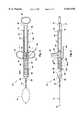
- FIGS. 1 and 2are fragmentary top plan and side elevational views, respectively, of surgical apparatus according to the present invention, in a "neutral” or “needle in, snare in” orientation;
- FIGS. 3, 4, and 5are fragmentary top plan, side elevational and bottom plan views, respectively, of the surgical apparatus in a "needle in, snare out" orientation;
- FIGS. 6 and 7are fragmentary sectional views thereof, taken along the lines 6--6 of FIG. 4 and 7--7 of FIG. 6, respectively;
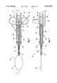
- FIGS. 8, 9 and 10are fragmentary top plan, side elevational and bottom plan views, respectively, of the surgical apparatus, in a "needle out, snare in” orientation;
- FIGS. 11 and 12are fragmentary sectional views thereof, taken along the lines 11--11 of FIG. 10 and 12--12 of FIG. 11, respectively;
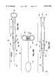
- FIGS. 13A, 13B and 13Ctogether form an exploded top plan view thereof separated into independently moveable assemblies.
- the improved surgical combination apparatusmay incorporate various first and second instruments. While the apparatus shown and described herein is a surgical combination inject and snare apparatus, wherein the first instrument is an injection needle and the second instrument is a snare, those skilled in the surgical arts will readily appreciate that the principles of the present invention have applicability to various other surgical combination apparatus.
- the surgical apparatus 10is a surgical combination inject and snare apparatus including, as a first instrument, a hollow injection needle 12 (best seen in FIGS. 8-12) and, as a second instrument, a snare 14 (best seen in FIGS. 3-7).
- the surgical apparatus 10includes sheathing means 16 for sheathing the first and second instruments 12, 14, actuator means, generally designated 18, for manually controlling movement of the various elements 12, 14 relative to one another, and biasing means 20.
- the sheathing means 16is a conventional catheter, formed of a flexible plastic and defining both an enlarged proximal end 30 fixedly secured to the actuator 18 and a distal or free end 32 for insertion into a patient.
- the actuator means 18includes means for manually extending the first instrument or needle 12 a substantially fixed first length, relative to the distal end 32 of the sheathing means 16, and for independently but non-simultaneously extending or retracting the second instrument or snare 14 a variable second length, relative to the distal end 32 of the sheathing means 16.
- the biasing means 20may be a conventional spring for biasing the first instrument or needle 12 into retracting relative to the distal end 32 of the sheathing means 16.
- the actuator means 18comprises a support assembly generally designated 40, a slider assembly generally designated 44, and a rail assembly generally designated 50.
- the axially or longitudinally extending rigid support assembly 40comprises a support 41 and means 42 for grasping thereof, such as a thumb ring at one end.
- the first instrument or hollow injection needle 12is secured to the support 41 by a hollow, flexible wire 43 for movement therewith as a unit.
- the support 41 at its distal end, adjacent the sheathing means 16,defines a hollow cylinder 62 with a closed proximal end and an open distal end.
- the hollow, flexible wire 43passes through cylinder 62 and provides fluid communication between needle 12 and hollow tubing 68, the latter being adapted for connection to a fluid source (not shown) and secured to support 41 for movement therewith.
- the slider assembly 44comprises a slider 45 and means 46 for grasping thereof, such as a pair of finger rings on opposite sides thereof.
- the slider 45is secured to the support assembly 40 for sliding longitudinal movement there along in both directions.
- the second instrument or snare 14is secured to the slider 45 by a typically solid, flexible electrically conductive wire 47 for movement therewith as a unit.
- An electrical contact 66adapted for conductive communication with a power source (not shown), is secured to slider 45 for movement as a unit therewith and provides for the communication of electrical energy to sheath 14 via conductive wire 47 passing through channel 60 and cylinder 62.
- the support 41 and channel 60 of support assembly 40are configured and dimensioned to receive the slider 45 of slider assembly 44 within the channel 60 and the grasping means 46 of slider assembly 44 laterally outwardly of the support 41, thereby permitting relative movement of the slider 45 and its finger rings 46 relative to the support 41 and its thumb ring 42.
- the needle 12is connected to the support assembly 40 by a flexible wire 43 and the snare 14 is connected to the slider assembly 44 by a flexible wire 47, the needle 12 and snare 14 are in turn capable of relative, albeit non-simultaneous, motion.
- the axially or longitudinally extending rail assembly 50is provided for enabling independent but non-simultaneous sliding movement of the first instrument or needle 12 in opposite directions relative to the distal end 32 of the sheathing means 16.
- the rail assembly 50includes a pair of parallel rail means 51 longitudinally slidable with respect to the support assembly 40.
- the proximal ends of the two rail means 51each define a small outer lug 70 facing outwardly from the rail means 51 and a small inner lug 72 facing inwardly from the rail means 51 (toward the support 41).
- the inner lugs 72are received within longitudinal recesses 75 on the outer surfaces of the rail means 51.
- the outer lugs 70act as a stop to limit relative proximal movement of the slider 45 relative to the rail means 51. Accordingly, neglecting any locking means discussed hereinafter, a proximal movement of the slider 45 until it contacts the outer lugs 70 of the rail means 51 results in a retraction of the second instrument or snare 14 relative to the distal end 32 of the sheathing means 16.
- the distal ends of the two rail means 51are secured together by a connector 74.
- the distal end of the connector 74tapers inwardly and defines a surface 76 adapted to receive the proximal end 78 of catheter 16, such that the entire catheter 16 (including its distal tip 32) moves as a unit with the connector 74 and rail means 51, and thus as a part of the rail assembly 50.
- Rotatably secured to the proximal end of the connector 74is a piston 80, which is configured and dimensioned to be slidingly received within the interior of cylinder 62 (along with the spring 20) through the cylinder open distal end.
- the piston 80is freely rotatable relative to the connector 74 over at least 45 degrees, but secured to the connector 74 for longitudinal movement as a unit.
- the support assembly 40 of FIG. 13A, the slider assembly 44 of FIG. 13B and the rail assembly 50 of FIG. 13Care each capable of independent sliding movement relative to one another, thereby to enable the unique motions of the present invention.
- Movement of the slider assembly 44 toward the distal extreme relative to the support assembly 40causes the second instrument or snare 14 to extend relative to the distal end 32 of the sheathing means 16, as illustrated in FIGS. 3-7. Movement of the slider assembly 44 towards the proximal extreme relative to the support assembly 40 causes the second instrument or snare 14 to retract relative to the catheter distal end 32 of the sheathing means 16, as illustrated in the neutral orientation of FIGS. 1-2.
- a lever 82projects radially outwardly from the proximal end of the piston 80 and for rotational and longitudinal travel herewith is configured and dimensioned for travel (with the entire rail assembly 50) along the L-shaped pathway 64 formed within the side wall of cylinder 62.
- the distal face 84 of piston 80is at all times disposed within the interior of cylinder 62 (e.g., due to stop pins, not shown) and acts to maintain the spring 20 within the interior of cylinder 62.
- the spring 20in turn acts to bias the piston 80 for rotation.
- the spring 20causes the piston 80 to rotate out of alignment with the longitudinal leg 64a. Because the inner lugs 72 on rail means 51 preferably abut the distal end of the longitudinal recesses 75, lever 82 cannot move distally (and the piston 80 is thus kept at least partially within cylinder 62 even in the absence of the aforementioned stop pins). Because the lever 82 abuts the distal end of the cylinder 62, it cannot move proximally.
- FIGS. 1 and 2the apparatus 10 is illustrated therein a "neutral" or “needle in, snare in” orientation such as might be used for introduction of the catheter distal tip 32 to the desired location within the patient's body. Neither the needle 12 nor the snare 14 project distally of the catheter distal tip 32 where they might interfere with the threading of the tip 32 through the patient's body.
- the piston 80is disposed almost entirely distally of the cylinder 62 with the lever 82 resting on the distal face of the cylinder 62.
- the proximal end of slider 45is adjacent to or contacting the outer lugs 70 of the rail means 51.
- the apparatus 10is illustrated therein in the "needle out, snare in” orientation.
- the lever 82is rotated until it is aligned with the longitudinal leg 64a of the L-shaped passageway 64 of cylinder 62.
- the finger grips 46 and thumb grip 42are used to move the slider 45 proximally first against the outer lugs 70 of the rail means 51 and then even further proximally until the rail means 51 (and thus the entire rail assembly 50) moves proximally.
- the inner lugs 72 of the rail means 51(best seen in FIG.
- the lever 82travels along the longitudinal leg 64a and the piston 80 progressively enters the hollow cylinder 62. Finally, the lever 82 becomes aligned with the transverse leg 64b and, under the influence of spring 20, moves along the transverse leg 64b, thereby blocking any further longitudinal movement of the rail assembly 50 relative to the support assembly 40.
- the length of longitudinal leg 64ais preferably about 0.75 inch, although it may be shorter or longer depending upon the desired travel of the first instrument 12.
- the catheter distal tip 32is initially set against the polyp by the surgeon and the movement to the "needle out, snare in” orientation is effected by a forward movement of the support assembly 40 relative to the rail assembly 50.
- the forward motionis driven and controlled by the thumb movement in thumb ring 42, but it must first be enabled by the manual pivoting of lever 82 into alignment with the longitudinal leg 64a (i.e., unlocking of lever 82).
- the apparatusis locked in the "needle out, snare in” orientation.
- the desired fluidmay be introduced into the polyp through hollow tubing 68, hollow wire 43, and needle 12 without further action on the part of the surgeon to maintain the injection needle 12 in place.
- the lever 82initially acted as a safety or locking mechanism, precluding any distal advancement of the needle 12 until the lever 82 was manually aligned with the longitudinal leg 64a.
- the apparatus 10is illustrated therein in the "needle in, snare out" orientation.
- the polypOnce the polyp has been injected with fluid from the injection needle 12, the latter is returned to the neutral orientation. From there, the surgeon has only to move the slider assembly 44 distally relative to the rail assembly 50. This is easily accomplished by separating the fingers in the finger grips 46 from the thumb in the thumb grip 42. The abutment of the distal end of the slider 45 against the distal end of the channel 60 limits the forward movement of the slider 45 (and hence the slider assembly 44) relative to the now locked together supra-assembly formed by the support assembly 40 and the rail assembly 50. It will be appreciated that the piston 80 and lever 82 and the cylinder 62 and passageway 64 play no role in the movement of the sheath 14 relative to the catheter distal end 32.
- the surgeonhas only to manipulate reciprocatingly the finger grips 46 relative to the thumb grip 42 in order to cause distal emergence of the sheath 14, trapping of the protruding polyp thereby, and withdrawal of the sheath 14 (either with or without the polyp) back into the catheter 16. Electrical energy may be introduced into the sheath 14 via contact 66 and electrically conductive wire 47.
- the movement of the injection needle 12is independent of the movement of the snare 14, thereby to reduce the force which must be exerted during either movement.
- the interaction of the lever 82 and the passageway 64provides a locking mechanism which must be manually unlocked in order to enable either extension or retraction of the needle, which enables the injection needle 12 to be maintained in the extended position without further action on the part of the surgeon, and which provides automatic retraction of the needle 12 when it is no longer required.
- the preferred embodimentallows the snare 14 to be extended a variable and sizable distance, limited essentially only by the length of channel 60, while the injection needle 12 is extendable only a much shorter distance, typically limited by the length of the longitudinal leg 64a.
- the extension of the needle 12is for the full extent of the short distance as the maintenance of the lever 82 within the longitudinal leg 64a is unstable due to the biasing of spring 20.
Landscapes
- Health & Medical Sciences (AREA)
- Life Sciences & Earth Sciences (AREA)
- Surgery (AREA)
- Heart & Thoracic Surgery (AREA)
- Engineering & Computer Science (AREA)
- Biomedical Technology (AREA)
- Nuclear Medicine, Radiotherapy & Molecular Imaging (AREA)
- Medical Informatics (AREA)
- Molecular Biology (AREA)
- Animal Behavior & Ethology (AREA)
- General Health & Medical Sciences (AREA)
- Public Health (AREA)
- Veterinary Medicine (AREA)
- Surgical Instruments (AREA)
Abstract
Description
Claims (4)
Priority Applications (4)
| Application Number | Priority Date | Filing Date | Title |
|---|---|---|---|
| US08/633,958US5947978A (en) | 1996-04-15 | 1996-04-15 | Surgical combination apparatus having first and second instruments operated from a common actuator |
| PCT/US1997/006290WO1997038630A1 (en) | 1996-04-15 | 1997-04-15 | Improved surgical combination apparatus |
| DE29723988UDE29723988U1 (en) | 1996-04-15 | 1997-04-15 | Improved combined surgical device |
| US09/351,593US6193729B1 (en) | 1996-04-15 | 1999-07-12 | Surgical combination apparatus having first and second instruments operated from a common actuator |
Applications Claiming Priority (1)
| Application Number | Priority Date | Filing Date | Title |
|---|---|---|---|
| US08/633,958US5947978A (en) | 1996-04-15 | 1996-04-15 | Surgical combination apparatus having first and second instruments operated from a common actuator |
Related Child Applications (1)
| Application Number | Title | Priority Date | Filing Date |
|---|---|---|---|
| US09/351,593ContinuationUS6193729B1 (en) | 1996-04-15 | 1999-07-12 | Surgical combination apparatus having first and second instruments operated from a common actuator |
Publications (1)
| Publication Number | Publication Date |
|---|---|
| US5947978Atrue US5947978A (en) | 1999-09-07 |
Family
ID=24541857
Family Applications (2)
| Application Number | Title | Priority Date | Filing Date |
|---|---|---|---|
| US08/633,958Expired - LifetimeUS5947978A (en) | 1996-04-15 | 1996-04-15 | Surgical combination apparatus having first and second instruments operated from a common actuator |
| US09/351,593Expired - LifetimeUS6193729B1 (en) | 1996-04-15 | 1999-07-12 | Surgical combination apparatus having first and second instruments operated from a common actuator |
Family Applications After (1)
| Application Number | Title | Priority Date | Filing Date |
|---|---|---|---|
| US09/351,593Expired - LifetimeUS6193729B1 (en) | 1996-04-15 | 1999-07-12 | Surgical combination apparatus having first and second instruments operated from a common actuator |
Country Status (2)
| Country | Link |
|---|---|
| US (2) | US5947978A (en) |
| WO (1) | WO1997038630A1 (en) |
Cited By (21)
| Publication number | Priority date | Publication date | Assignee | Title |
|---|---|---|---|---|
| US6080176A (en)* | 1998-10-30 | 2000-06-27 | Atrion Medical Products, Inc. | Medical punch with high shear angle cutting edges |
| US6193729B1 (en)* | 1996-04-15 | 2001-02-27 | Ballard Medical Products | Surgical combination apparatus having first and second instruments operated from a common actuator |
| US6371963B1 (en)* | 1998-11-17 | 2002-04-16 | Scimed Life Systems, Inc. | Device for controlled endoscopic penetration of injection needle |
| US20020107526A1 (en)* | 2000-11-03 | 2002-08-08 | Cook Incorporated | Medical grasping device |
| US6602262B2 (en)* | 2000-06-02 | 2003-08-05 | Scimed Life Systems, Inc. | Medical device having linear to rotation control |
| US20040249278A1 (en)* | 2003-06-04 | 2004-12-09 | Krause William R. | Biopsy and delivery device |
| US20050159648A1 (en)* | 2004-01-21 | 2005-07-21 | Scimed Life Systems, Inc. | Endoscopic device having spray mechanism and related methods of use |
| US20060100614A1 (en)* | 2004-11-10 | 2006-05-11 | Long Gary L | Tissue resection device |
| US20070088370A1 (en)* | 2005-10-14 | 2007-04-19 | Applied Medical Resources Corporation | Tissue retrieval system |
| US20070135781A1 (en)* | 2005-10-14 | 2007-06-14 | Applied Medical Resources Corporation | Device for isolating and removing tissue from a body cavity |
| JP2009528851A (en)* | 2005-12-28 | 2009-08-13 | シー・アール・バード・インコーポレイテツド | Apparatus and method for inserting an implant |
| US7713275B2 (en) | 2000-11-03 | 2010-05-11 | Cook Incorporated | Medical grasping device |
| US7753917B2 (en) | 2000-11-03 | 2010-07-13 | Cook Incorporated | Medical grasping device |
| US20110087235A1 (en)* | 2009-10-09 | 2011-04-14 | Applied Medical Resources Corporation | Single incision laparoscopic tissue retrieval system |
| US20130053727A1 (en)* | 2003-05-30 | 2013-02-28 | Boston Scientific Scimed, Inc. | Transbronchial Needle Aspiration Device |
| US8480559B2 (en) | 2006-09-13 | 2013-07-09 | C. R. Bard, Inc. | Urethral support system |
| US8574149B2 (en) | 2007-11-13 | 2013-11-05 | C. R. Bard, Inc. | Adjustable tissue support member |
| US8845512B2 (en) | 2005-11-14 | 2014-09-30 | C. R. Bard, Inc. | Sling anchor system |
| US8956370B2 (en) | 2010-10-01 | 2015-02-17 | Applied Medical Resources Corporation | Laparoscopic tissue retrieval system |
| US11547428B2 (en) | 2019-11-15 | 2023-01-10 | Applied Medical Resources Corporation | Redeploy able tissue retrieval system |
| US11707263B2 (en) | 2018-11-16 | 2023-07-25 | Applied Medical Resources Corporation | Tissue retrieval system with retention features |
Families Citing this family (10)
| Publication number | Priority date | Publication date | Assignee | Title |
|---|---|---|---|---|
| US6379319B1 (en) | 1996-10-11 | 2002-04-30 | Transvascular, Inc. | Systems and methods for directing and snaring guidewires |
| US5961526A (en)* | 1998-02-18 | 1999-10-05 | Boston Scientific Corporation | Coaxial needle and severing snare |
| US6221039B1 (en) | 1998-10-26 | 2001-04-24 | Scimed Life Systems, Inc. | Multi-function surgical instrument |
| US6007546A (en)* | 1998-10-26 | 1999-12-28 | Boston Scientific Ltd. | Injection snare |
| US6162209A (en) | 1998-11-17 | 2000-12-19 | Scimed Life Systems, Inc. | Multi-function surgical instrument tool actuator assembly |
| AU2003200448B2 (en)* | 1998-11-17 | 2005-10-06 | Boston Scientific Limited | Multi-function surgical instrument tool actuator assembly |
| US7635342B2 (en)* | 2001-05-06 | 2009-12-22 | Stereotaxis, Inc. | System and methods for medical device advancement and rotation |
| JP4940391B2 (en)* | 2004-11-24 | 2012-05-30 | クック メディカル テクノロジーズ エルエルシー | Improvement of sphincterotome |
| WO2007098231A2 (en)* | 2006-02-21 | 2007-08-30 | Cook Incorporated | Implant retrieval assemby and method for retrieving an implant |
| US8518050B2 (en) | 2007-10-31 | 2013-08-27 | DePuy Synthes Products, LLC | Modular taper assembly device |
Citations (25)
| Publication number | Priority date | Publication date | Assignee | Title |
|---|---|---|---|---|
| US2162681A (en)* | 1938-06-13 | 1939-06-13 | Henry Lange | Bronchoscope |
| US2856933A (en)* | 1958-01-27 | 1958-10-21 | Hildebrand Herbert | Surgical snare |
| US4085743A (en)* | 1976-03-02 | 1978-04-25 | In Bae Yoon | Multiple occlusion ring applicator and method |
| US4222380A (en)* | 1977-12-02 | 1980-09-16 | Olympus Optical Co., Ltd. | Celiac injector |
| US4592341A (en)* | 1984-05-23 | 1986-06-03 | Olympus Optical Co., Ltd. | Method and apparatus for guiding prosthesis |
| US4598699A (en)* | 1985-06-10 | 1986-07-08 | Garren Lloyd R | Endoscopic instrument for removing stomach insert |
| US4807626A (en)* | 1985-02-14 | 1989-02-28 | Mcgirr Douglas B | Stone extractor and method |
| US4832023A (en)* | 1987-06-03 | 1989-05-23 | Mcm Laboratories, Inc. | Method and apparatus for reducing blockage in body channels |
| US5026366A (en)* | 1984-03-01 | 1991-06-25 | Cardiovascular Laser Systems, Inc. | Angioplasty catheter and method of use thereof |
| US5026377A (en)* | 1989-07-13 | 1991-06-25 | American Medical Systems, Inc. | Stent placement instrument and method |
| US5084054A (en)* | 1990-03-05 | 1992-01-28 | C.R. Bard, Inc. | Surgical gripping instrument |
| US5163942A (en)* | 1991-12-09 | 1992-11-17 | Everest Medical Corporation | Surgical instrument with grasping loop for laparoscopic procedures |
| US5176688A (en)* | 1991-07-17 | 1993-01-05 | Perinchery Narayan | Stone extractor and method |
| US5190542A (en)* | 1991-11-05 | 1993-03-02 | Nakao Naomi L | Surgical retrieval assembly and related method |
| US5224931A (en)* | 1991-04-23 | 1993-07-06 | Kumar Sarbjeet S | Method and device for performing cholangiography |
| US5241970A (en)* | 1991-05-17 | 1993-09-07 | Wilson-Cook Medical, Inc. | Papillotome/sphincterotome procedures and a wire guide specially |
| US5290299A (en)* | 1991-12-11 | 1994-03-01 | Ventritex, Inc. | Double jaw apparatus for attaching implanted materials to body tissue |
| US5290294A (en)* | 1990-04-17 | 1994-03-01 | Brian Cox | Method and apparatus for removal of a foreign body cavity |
| US5334143A (en)* | 1992-04-17 | 1994-08-02 | Carroll Brendon J | Method to remove common bile duct stones |
| US5336227A (en)* | 1991-11-05 | 1994-08-09 | Wilk & Nakao Medical Technology Incorporated | Surgical cauterization snare with polyp capturing web net |
| US5376094A (en)* | 1993-08-19 | 1994-12-27 | Boston Scientific Corporation | Improved actuating handle with pulley system for providing mechanical advantage to a surgical working element |
| US5395367A (en)* | 1992-07-29 | 1995-03-07 | Wilk; Peter J. | Laparoscopic instrument with bendable shaft and removable actuator |
| US5456694A (en)* | 1994-05-13 | 1995-10-10 | Stentco, Inc. | Device for delivering and deploying intraluminal devices |
| US5542948A (en)* | 1994-05-24 | 1996-08-06 | Arrow Precision Products, Inc. | Surgical combination inject and snare apparatus |
| US5653716A (en)* | 1994-12-29 | 1997-08-05 | Acufex Microsurgical, Inc. | Suture manipulating instrument with grasping members |
Family Cites Families (7)
| Publication number | Priority date | Publication date | Assignee | Title |
|---|---|---|---|---|
| US4815476A (en) | 1988-03-28 | 1989-03-28 | Cordis Corporation | Biopsy forceps with locking handle |
| US4911693A (en)* | 1988-10-17 | 1990-03-27 | Paris Frassetti R | Hypodermic syringe needle guard |
| US5201708A (en)* | 1992-02-03 | 1993-04-13 | Timothy A. Kershenstine | Self-locking safety syringe |
| JP3688355B2 (en) | 1995-08-03 | 2005-08-24 | 株式会社町田製作所 | Endoscopy forceps device |
| US5947978A (en)* | 1996-04-15 | 1999-09-07 | Medical Innovations Corp. | Surgical combination apparatus having first and second instruments operated from a common actuator |
| US5921915A (en) | 1997-04-30 | 1999-07-13 | C.R. Bard, Inc. | Directional surgical device for use with endoscope, gastroscope, colonoscope or the like |
| FR2762985B1 (en) | 1997-05-06 | 1999-08-20 | Visco | MODULAR SURGERY DEVICE FOR ENDOSCOPIC SURGERY AND CLASSICAL SURGERY |
- 1996
- 1996-04-15USUS08/633,958patent/US5947978A/ennot_activeExpired - Lifetime
- 1997
- 1997-04-15WOPCT/US1997/006290patent/WO1997038630A1/enactiveApplication Filing
- 1999
- 1999-07-12USUS09/351,593patent/US6193729B1/ennot_activeExpired - Lifetime
Patent Citations (26)
| Publication number | Priority date | Publication date | Assignee | Title |
|---|---|---|---|---|
| US2162681A (en)* | 1938-06-13 | 1939-06-13 | Henry Lange | Bronchoscope |
| US2856933A (en)* | 1958-01-27 | 1958-10-21 | Hildebrand Herbert | Surgical snare |
| US4085743A (en)* | 1976-03-02 | 1978-04-25 | In Bae Yoon | Multiple occlusion ring applicator and method |
| US4222380A (en)* | 1977-12-02 | 1980-09-16 | Olympus Optical Co., Ltd. | Celiac injector |
| US5026366A (en)* | 1984-03-01 | 1991-06-25 | Cardiovascular Laser Systems, Inc. | Angioplasty catheter and method of use thereof |
| US5437659A (en)* | 1984-03-01 | 1995-08-01 | Eli Lilly And Company | Angioplasty catheter and method of use thereof |
| US4592341A (en)* | 1984-05-23 | 1986-06-03 | Olympus Optical Co., Ltd. | Method and apparatus for guiding prosthesis |
| US4807626A (en)* | 1985-02-14 | 1989-02-28 | Mcgirr Douglas B | Stone extractor and method |
| US4598699A (en)* | 1985-06-10 | 1986-07-08 | Garren Lloyd R | Endoscopic instrument for removing stomach insert |
| US4832023A (en)* | 1987-06-03 | 1989-05-23 | Mcm Laboratories, Inc. | Method and apparatus for reducing blockage in body channels |
| US5026377A (en)* | 1989-07-13 | 1991-06-25 | American Medical Systems, Inc. | Stent placement instrument and method |
| US5084054A (en)* | 1990-03-05 | 1992-01-28 | C.R. Bard, Inc. | Surgical gripping instrument |
| US5290294A (en)* | 1990-04-17 | 1994-03-01 | Brian Cox | Method and apparatus for removal of a foreign body cavity |
| US5224931A (en)* | 1991-04-23 | 1993-07-06 | Kumar Sarbjeet S | Method and device for performing cholangiography |
| US5241970A (en)* | 1991-05-17 | 1993-09-07 | Wilson-Cook Medical, Inc. | Papillotome/sphincterotome procedures and a wire guide specially |
| US5176688A (en)* | 1991-07-17 | 1993-01-05 | Perinchery Narayan | Stone extractor and method |
| US5190542A (en)* | 1991-11-05 | 1993-03-02 | Nakao Naomi L | Surgical retrieval assembly and related method |
| US5336227A (en)* | 1991-11-05 | 1994-08-09 | Wilk & Nakao Medical Technology Incorporated | Surgical cauterization snare with polyp capturing web net |
| US5163942A (en)* | 1991-12-09 | 1992-11-17 | Everest Medical Corporation | Surgical instrument with grasping loop for laparoscopic procedures |
| US5290299A (en)* | 1991-12-11 | 1994-03-01 | Ventritex, Inc. | Double jaw apparatus for attaching implanted materials to body tissue |
| US5334143A (en)* | 1992-04-17 | 1994-08-02 | Carroll Brendon J | Method to remove common bile duct stones |
| US5395367A (en)* | 1992-07-29 | 1995-03-07 | Wilk; Peter J. | Laparoscopic instrument with bendable shaft and removable actuator |
| US5376094A (en)* | 1993-08-19 | 1994-12-27 | Boston Scientific Corporation | Improved actuating handle with pulley system for providing mechanical advantage to a surgical working element |
| US5456694A (en)* | 1994-05-13 | 1995-10-10 | Stentco, Inc. | Device for delivering and deploying intraluminal devices |
| US5542948A (en)* | 1994-05-24 | 1996-08-06 | Arrow Precision Products, Inc. | Surgical combination inject and snare apparatus |
| US5653716A (en)* | 1994-12-29 | 1997-08-05 | Acufex Microsurgical, Inc. | Suture manipulating instrument with grasping members |
Cited By (51)
| Publication number | Priority date | Publication date | Assignee | Title |
|---|---|---|---|---|
| US6193729B1 (en)* | 1996-04-15 | 2001-02-27 | Ballard Medical Products | Surgical combination apparatus having first and second instruments operated from a common actuator |
| US6080176A (en)* | 1998-10-30 | 2000-06-27 | Atrion Medical Products, Inc. | Medical punch with high shear angle cutting edges |
| US6371963B1 (en)* | 1998-11-17 | 2002-04-16 | Scimed Life Systems, Inc. | Device for controlled endoscopic penetration of injection needle |
| US20080234695A1 (en)* | 1998-11-17 | 2008-09-25 | Boston Scientific Scimed, Inc. | Device for controlled endoscopic penetration of injection needle |
| US7402163B2 (en)* | 1998-11-17 | 2008-07-22 | Boston Scientific Scimed, Inc. | Device for controlled endoscopic penetration of injection needle |
| US20030216753A1 (en)* | 1998-11-17 | 2003-11-20 | Srinivas Nishtala | Device for controlled endoscopic penetration of injection needle |
| US6663645B2 (en) | 1998-11-17 | 2003-12-16 | Scimed Life Systems, Inc. | Device for controlled endoscopic penetration of injection needle |
| US8758363B2 (en) | 1998-11-17 | 2014-06-24 | Boston Scientific Scimed, Inc. | Device for controlled endoscopic penetration of injection needle |
| US8187291B2 (en) | 1998-11-17 | 2012-05-29 | Boston Scientific Scimed, Inc. | Device for controlled endoscopic penetration of injection needle |
| US6843792B2 (en) | 1998-11-17 | 2005-01-18 | Scimed Life Systems, Inc. | Device for controlled endoscopic penetration of injection needle |
| US20050096506A1 (en)* | 1998-11-17 | 2005-05-05 | Scimed Life Systems, Inc. | Device for controlled endoscopic penetration of injection needle |
| US8771288B2 (en) | 2000-06-02 | 2014-07-08 | Boston Scientific Scimed, Inc. | Medical device having linear to rotation control |
| US20040030350A1 (en)* | 2000-06-02 | 2004-02-12 | Scimed Life Systems, Inc. | Medical device having linear to rotation control |
| US8388629B2 (en) | 2000-06-02 | 2013-03-05 | Boston Scientific Scimed, Inc. | Medical device having linear to rotation control |
| US6602262B2 (en)* | 2000-06-02 | 2003-08-05 | Scimed Life Systems, Inc. | Medical device having linear to rotation control |
| US7758591B2 (en) | 2000-06-02 | 2010-07-20 | Boston Scientific Scimed, Inc. | Medical device having linear to rotation control |
| US20100286707A1 (en)* | 2000-06-02 | 2010-11-11 | Boston Scientific Scimed, Inc. | Medical Device Having Linear to Rotation Control |
| US20020107526A1 (en)* | 2000-11-03 | 2002-08-08 | Cook Incorporated | Medical grasping device |
| US7713275B2 (en) | 2000-11-03 | 2010-05-11 | Cook Incorporated | Medical grasping device |
| US7753917B2 (en) | 2000-11-03 | 2010-07-13 | Cook Incorporated | Medical grasping device |
| US7776052B2 (en) | 2000-11-03 | 2010-08-17 | Cook Incorporated | Medical grasping device |
| US20130053727A1 (en)* | 2003-05-30 | 2013-02-28 | Boston Scientific Scimed, Inc. | Transbronchial Needle Aspiration Device |
| US20040249278A1 (en)* | 2003-06-04 | 2004-12-09 | Krause William R. | Biopsy and delivery device |
| US7169114B2 (en)* | 2003-06-04 | 2007-01-30 | Krause William R | Biopsy and delivery device |
| US20050159648A1 (en)* | 2004-01-21 | 2005-07-21 | Scimed Life Systems, Inc. | Endoscopic device having spray mechanism and related methods of use |
| US20110230720A1 (en)* | 2004-01-21 | 2011-09-22 | Boston Scientific Limited | Endoscopic device having spray mechanism and related methods of use |
| US7951073B2 (en) | 2004-01-21 | 2011-05-31 | Boston Scientific Limited | Endoscopic device having spray mechanism and related methods of use |
| US20060100614A1 (en)* | 2004-11-10 | 2006-05-11 | Long Gary L | Tissue resection device |
| US8216234B2 (en) | 2004-11-10 | 2012-07-10 | Ethicon Endo-Surgery, Inc. | Tissue resection device |
| US11357524B2 (en) | 2005-10-14 | 2022-06-14 | Applied Medical Resources Corporation | Tissue retrieval system |
| US10537345B2 (en) | 2005-10-14 | 2020-01-21 | Applied Medical Resources Corporation | Tissue retrieval system |
| US20070135781A1 (en)* | 2005-10-14 | 2007-06-14 | Applied Medical Resources Corporation | Device for isolating and removing tissue from a body cavity |
| US9579115B2 (en) | 2005-10-14 | 2017-02-28 | Applied Medical Resources Corporation | Tissue retrieval system |
| US8652147B2 (en) | 2005-10-14 | 2014-02-18 | Applied Medical Resources Corporation | Device for isolating and removing tissue from a body cavity |
| US8721658B2 (en)* | 2005-10-14 | 2014-05-13 | Applied Medical Resources Corporation | Tissue retrieval system |
| US20070088370A1 (en)* | 2005-10-14 | 2007-04-19 | Applied Medical Resources Corporation | Tissue retrieval system |
| US8845512B2 (en) | 2005-11-14 | 2014-09-30 | C. R. Bard, Inc. | Sling anchor system |
| JP2009528851A (en)* | 2005-12-28 | 2009-08-13 | シー・アール・バード・インコーポレイテツド | Apparatus and method for inserting an implant |
| US8480559B2 (en) | 2006-09-13 | 2013-07-09 | C. R. Bard, Inc. | Urethral support system |
| US8574149B2 (en) | 2007-11-13 | 2013-11-05 | C. R. Bard, Inc. | Adjustable tissue support member |
| US9033995B2 (en) | 2009-10-09 | 2015-05-19 | Applied Medical Resources Corporation | Single incision laparoscopic tissue retrieval system |
| US10245053B2 (en) | 2009-10-09 | 2019-04-02 | Applied Medical Resources Corporation | Single incision laparoscopic tissue retrieval system |
| US11191557B2 (en) | 2009-10-09 | 2021-12-07 | Applied Medical Resources Corporation | Single incision laparoscopic tissue retrieval system |
| US20110087235A1 (en)* | 2009-10-09 | 2011-04-14 | Applied Medical Resources Corporation | Single incision laparoscopic tissue retrieval system |
| US11969179B2 (en) | 2009-10-09 | 2024-04-30 | Applied Medical Resources Corporation | Single incision laparoscopic tissue retrieval system |
| US9949748B2 (en) | 2010-10-01 | 2018-04-24 | Applied Medical Resources Corporation | Laparoscopic tissue retrieval system |
| US8956370B2 (en) | 2010-10-01 | 2015-02-17 | Applied Medical Resources Corporation | Laparoscopic tissue retrieval system |
| US11707263B2 (en) | 2018-11-16 | 2023-07-25 | Applied Medical Resources Corporation | Tissue retrieval system with retention features |
| US12268376B2 (en) | 2018-11-16 | 2025-04-08 | Applied Medical Resources Corporation | Tissue retrieval system with retention features |
| US11547428B2 (en) | 2019-11-15 | 2023-01-10 | Applied Medical Resources Corporation | Redeploy able tissue retrieval system |
| US12193693B2 (en) | 2019-11-15 | 2025-01-14 | Applied Medical Resources Corporation | Redeployable tissue retrieval system |
Also Published As
| Publication number | Publication date |
|---|---|
| WO1997038630A1 (en) | 1997-10-23 |
| US6193729B1 (en) | 2001-02-27 |
Similar Documents
| Publication | Publication Date | Title |
|---|---|---|
| US5947978A (en) | Surgical combination apparatus having first and second instruments operated from a common actuator | |
| US7217264B2 (en) | Multi-function surgical instrument tool actuator assembly | |
| US5084054A (en) | Surgical gripping instrument | |
| US5286255A (en) | Surgical forceps | |
| US6641595B1 (en) | Laparoscopic forceps handle | |
| US5251638A (en) | Biopsy forceps device having improved handle assembly | |
| US5609601A (en) | Endoscopic surgical apparatus with rotation lock | |
| JP6104336B2 (en) | Electrosurgical instrument | |
| EP1230899B1 (en) | Deployable surgical clamp with delivery/retrieval device and actuator | |
| JP2019213965A5 (en) | ||
| US12011147B2 (en) | Actuation handle for accessory devices | |
| CA2072059A1 (en) | Surgical drill guide | |
| US5643248A (en) | Medical instrument with force limiting mechanism | |
| CN112469346A (en) | Medical handle | |
| US5573511A (en) | Retractable safety penetrating instrument with safety probe | |
| US20190069915A1 (en) | Endoscope Tool | |
| US12114910B2 (en) | Suction actuated electrocautery and suction device | |
| EP1654992B1 (en) | Deployable surgical clamp with delivery/retrieval device and actuator | |
| US20220361735A1 (en) | Clip device for endoscope | |
| US20050096663A1 (en) | Control apparatus for actuating an elongate medical shaft | |
| DE2921094C2 (en) | Ring applicator |
Legal Events
| Date | Code | Title | Description |
|---|---|---|---|
| AS | Assignment | Owner name:ARROW PRECISION PRODUCTS, INC., PENNSYLVANIA Free format text:ASSIGNMENT OF ASSIGNORS INTEREST;ASSIGNOR:HOLSINGER, DAMOND C.;REEL/FRAME:007962/0511 Effective date:19960408 | |
| AS | Assignment | Owner name:MEDICAL INNOVATIONS CORPORATION, UTAH Free format text:ASSIGNMENT OF ASSIGNORS INTEREST;ASSIGNOR:ARROW PRECISION PRODUCTS, INC.;REEL/FRAME:007984/0335 Effective date:19960419 | |
| STCF | Information on status: patent grant | Free format text:PATENTED CASE | |
| AS | Assignment | Owner name:BALLARD MEDICAL PRODUCTS, UTAH Free format text:ASSIGNMENT OF ASSIGNORS INTEREST;ASSIGNOR:MEDICAL INNOVATIONS CORPORATION;REEL/FRAME:013608/0442 Effective date:20021219 | |
| FPAY | Fee payment | Year of fee payment:4 | |
| FEPP | Fee payment procedure | Free format text:PAYER NUMBER DE-ASSIGNED (ORIGINAL EVENT CODE: RMPN); ENTITY STATUS OF PATENT OWNER: LARGE ENTITY Free format text:PAYOR NUMBER ASSIGNED (ORIGINAL EVENT CODE: ASPN); ENTITY STATUS OF PATENT OWNER: LARGE ENTITY | |
| FPAY | Fee payment | Year of fee payment:8 | |
| AS | Assignment | Owner name:KIMBERLY-CLARK WORLDWIDE, INC., WISCONSIN Free format text:ASSIGNMENT OF ASSIGNORS INTEREST;ASSIGNOR:BALLARD MEDICAL PRODUCTS, INC.;REEL/FRAME:019805/0150 Effective date:20070910 | |
| FPAY | Fee payment | Year of fee payment:12 | |
| AS | Assignment | Owner name:AVENT, INC., GEORGIA Free format text:ASSIGNMENT OF ASSIGNORS INTEREST;ASSIGNOR:KIMBERLY-CLARK WORLDWIDE, INC.;REEL/FRAME:034756/0001 Effective date:20141030 | |
| AS | Assignment | Owner name:MORGAN STANLEY SENIOR FUNDING, INC., NEW YORK Free format text:SECURITY INTEREST;ASSIGNOR:AVENT, INC.;REEL/FRAME:035375/0867 Effective date:20150227 | |
| AS | Assignment | Owner name:CITIBANK, N.A., NEW YORK Free format text:INTELLECTUAL PROPERTY SECURITY INTEREST ASSIGNMENT AGREEMENT;ASSIGNOR:MORGAN STANLEY SENIOR FUNDING, INC.;REEL/FRAME:048173/0137 Effective date:20181029 | |
| AS | Assignment | Owner name:AVANOS MEDICAL SALES, LLC, GEORGIA Free format text:RELEASE BY SECURED PARTY;ASSIGNOR:CITIBANK, N.A.;REEL/FRAME:060557/0062 Effective date:20220624 Owner name:AVENT, INC., GEORGIA Free format text:RELEASE BY SECURED PARTY;ASSIGNOR:CITIBANK, N.A.;REEL/FRAME:060557/0062 Effective date:20220624 |