US5946870A - Panel support construction accessory - Google Patents
Panel support construction accessoryDownload PDFInfo
- Publication number
- US5946870A US5946870AUS09/059,743US5974398AUS5946870AUS 5946870 AUS5946870 AUS 5946870AUS 5974398 AUS5974398 AUS 5974398AUS 5946870 AUS5946870 AUS 5946870A
- Authority
- US
- United States
- Prior art keywords
- flange
- accessory
- bottom flange
- extending
- perforations
- Prior art date
- Legal status (The legal status is an assumption and is not a legal conclusion. Google has not performed a legal analysis and makes no representation as to the accuracy of the status listed.)
- Expired - Lifetime
Links
- 238000010276constructionMethods0.000titleclaimsabstractdescription121
- 239000000463materialSubstances0.000claimsabstractdescription43
- 230000001413cellular effectEffects0.000claimsabstractdescription5
- 125000006850spacer groupChemical group0.000claimsdescription38
- 238000000576coating methodMethods0.000claimsdescription13
- 239000011248coating agentSubstances0.000claimsdescription12
- 239000006260foamSubstances0.000claims2
- 230000004888barrier functionEffects0.000description7
- 238000000034methodMethods0.000description7
- 241000238631HexapodaSpecies0.000description4
- 239000011324beadSubstances0.000description4
- 229920000642polymerPolymers0.000description4
- -1stuccoSubstances0.000description4
- 241000256602IsopteraSpecies0.000description3
- 239000012530fluidSubstances0.000description3
- 238000004519manufacturing processMethods0.000description3
- 239000004800polyvinyl chlorideSubstances0.000description3
- 229920000915polyvinyl chloridePolymers0.000description3
- 238000012216screeningMethods0.000description3
- 125000000391vinyl groupChemical group[H]C([*])=C([H])[H]0.000description3
- 229920002554vinyl polymerPolymers0.000description3
- 229910001335Galvanized steelInorganic materials0.000description2
- 241000256626Pterygota <winged insects>Species0.000description2
- 239000000853adhesiveSubstances0.000description2
- 230000001070adhesive effectEffects0.000description2
- 229910052782aluminiumInorganic materials0.000description2
- XAGFODPZIPBFFR-UHFFFAOYSA-NaluminiumChemical compound[Al]XAGFODPZIPBFFR-UHFFFAOYSA-N0.000description2
- 230000004323axial lengthEffects0.000description2
- 230000008859changeEffects0.000description2
- 239000008397galvanized steelSubstances0.000description2
- 239000011159matrix materialSubstances0.000description2
- 229910052751metalInorganic materials0.000description2
- 239000002184metalSubstances0.000description2
- 150000002739metalsChemical class0.000description2
- 238000003466weldingMethods0.000description2
- 239000004593EpoxySubstances0.000description1
- 238000009825accumulationMethods0.000description1
- NIXOWILDQLNWCW-UHFFFAOYSA-Nacrylic acid groupChemical groupC(C=C)(=O)ONIXOWILDQLNWCW-UHFFFAOYSA-N0.000description1
- 238000004220aggregationMethods0.000description1
- 230000002776aggregationEffects0.000description1
- 230000000712assemblyEffects0.000description1
- 238000000429assemblyMethods0.000description1
- 239000004568cementSubstances0.000description1
- 238000009833condensationMethods0.000description1
- 230000005494condensationEffects0.000description1
- 230000008602contractionEffects0.000description1
- 125000003700epoxy groupChemical group0.000description1
- 239000003292glueSubstances0.000description1
- 239000010440gypsumSubstances0.000description1
- 229910052602gypsumInorganic materials0.000description1
- 238000009413insulationMethods0.000description1
- 239000007788liquidSubstances0.000description1
- 239000003607modifierSubstances0.000description1
- 238000010422paintingMethods0.000description1
- 229920000647polyepoxidePolymers0.000description1
- 230000008569processEffects0.000description1
- 238000004080punchingMethods0.000description1
- 230000002787reinforcementEffects0.000description1
- 239000007787solidSubstances0.000description1
- 239000007858starting materialSubstances0.000description1
- 229920001169thermoplasticPolymers0.000description1
- 229920001187thermosetting polymerPolymers0.000description1
- 239000004416thermosoftening plasticSubstances0.000description1
- 238000009423ventilationMethods0.000description1
Images

Classifications
- E—FIXED CONSTRUCTIONS
- E04—BUILDING
- E04B—GENERAL BUILDING CONSTRUCTIONS; WALLS, e.g. PARTITIONS; ROOFS; FLOORS; CEILINGS; INSULATION OR OTHER PROTECTION OF BUILDINGS
- E04B1/00—Constructions in general; Structures which are not restricted either to walls, e.g. partitions, or floors or ceilings or roofs
- E04B1/62—Insulation or other protection; Elements or use of specified material therefor
- E04B1/74—Heat, sound or noise insulation, absorption, or reflection; Other building methods affording favourable thermal or acoustical conditions, e.g. accumulating of heat within walls
- E04B1/76—Heat, sound or noise insulation, absorption, or reflection; Other building methods affording favourable thermal or acoustical conditions, e.g. accumulating of heat within walls specifically with respect to heat only
- E04B1/762—Exterior insulation of exterior walls
- E04B1/765—Bottom edge finishing profile
- E—FIXED CONSTRUCTIONS
- E04—BUILDING
- E04F—FINISHING WORK ON BUILDINGS, e.g. STAIRS, FLOORS
- E04F13/00—Coverings or linings, e.g. for walls or ceilings
- E04F13/02—Coverings or linings, e.g. for walls or ceilings of plastic materials hardening after applying, e.g. plaster
- E04F13/04—Bases for plaster
- E04F13/06—Edge-protecting borders
- E—FIXED CONSTRUCTIONS
- E04—BUILDING
- E04F—FINISHING WORK ON BUILDINGS, e.g. STAIRS, FLOORS
- E04F13/00—Coverings or linings, e.g. for walls or ceilings
- E04F13/07—Coverings or linings, e.g. for walls or ceilings composed of covering or lining elements; Sub-structures therefor; Fastening means therefor
- E04F13/08—Coverings or linings, e.g. for walls or ceilings composed of covering or lining elements; Sub-structures therefor; Fastening means therefor composed of a plurality of similar covering or lining elements
- E—FIXED CONSTRUCTIONS
- E04—BUILDING
- E04F—FINISHING WORK ON BUILDINGS, e.g. STAIRS, FLOORS
- E04F19/00—Other details of constructional parts for finishing work on buildings
- E04F19/02—Borders; Finishing strips, e.g. beadings; Light coves
- E—FIXED CONSTRUCTIONS
- E04—BUILDING
- E04F—FINISHING WORK ON BUILDINGS, e.g. STAIRS, FLOORS
- E04F13/00—Coverings or linings, e.g. for walls or ceilings
- E04F13/02—Coverings or linings, e.g. for walls or ceilings of plastic materials hardening after applying, e.g. plaster
- E04F13/04—Bases for plaster
- E04F13/06—Edge-protecting borders
- E04F2013/065—Edge-protecting borders for lower edges of outer insulation layers
Definitions
- the present inventionrelates to construction accessories.
- the present inventionrelates to a panel support construction accessory utilized in a wall structure, wherein a panel support construction accessory partially encloses a construction panel and removes moisture from about the construction panel.
- Panel support construction accessoriescome in a variety of different configurations, shapes and sizes, and serve a variety of different functions in exterior construction applications.
- Panel support construction accessoriesgenerally include a plurality of flanges obliquely extending relative to one another to form a channel sized to receive a construction panel.
- Panel support construction accessorieshave various uses, such as supporting panels, supporting coatings of construction fluid materials adjacent the panels, producing durable straight lines, smooth curves and arches, providing soffit ventilation, controlling expansion and contraction and protecting corners and edges.
- Panel support construction assembliesfurther protect and preserve edges of construction panels, such as wallboard, sheathing, and insulation boards from impact and condensation.
- Panel support construction accessoriesare commonly known by various names, including but not limited to, corner beads, casing beads, starter strip/casing beads, reinforced, drip casing beads, controlled joints and soffit vents. Panel support construction accessories are used in exterior finishing systems known as direct exterior finishing systems (DEFS) and exterior insulated finishing systems (EIFS).
- DEFSdirect exterior finishing systems
- EIFSexterior insulated finishing systems
- Panel support construction accessoriesare typically supported adjacent a support structure lined with a moisture barrier. After a construction panel is inserted into the channel of the panel support construction accessory, the front of the accessory as well as the front of the construction panel are typically coated with a polymer based or polymer modified exterior construction fluid material, such as stucco, cement matrix material or gypsum matrix materials, including acrylic modifiers, or are lined with a preformed sheet of weatherproof material.
- a polymer based or polymer modified exterior construction fluid materialsuch as stucco, cement matrix material or gypsum matrix materials, including acrylic modifiers
- the panel support construction accessory, moisture barrier and the outer coating, or sheet of weatherproof materialform an enclosure partially surrounding and encasing the construction panel. In addition to encasing the construction panel, the enclosure traps moisture adjacent to the construction panel. Unless perfectly sealed, additional moisture may enter the system through various cracks or openings.
- trapped moisturemay change state from a liquid to a solid (ice) and expand in volume. This change in volume further damages the enclosure by causing the coating to crack or by causing deformation of the panel support construction accessory.
- any methods used to vent moisture from the enclosurenot enable wind-blown moisture to re-enter the enclosure or allow insects, such as flying termites, to enter the enclosure.
- the present inventionis directed to a panel support construction accessory including a back flange and a bottom flange extending from the back flange.
- the bottom flangeincludes an array of perforations extending through the bottom flange.
- the array of perforationshave a maximum diameter of about one-eighth of an inch.
- the panel support construction accessoryincludes a lower flange coupled to the bottom flange and spaced from the bottom flange to form a cavity below the array of perforations.
- a spaceris coupled between the bottom flange and the lower flange.
- the spaceris welded to the bottom flange and the lower flange.
- the lower flangeprovides a surface adjacent the cavity which downwardly slopes away from the back flange and away from the bottom flange.
- the panel support construction accessoryadditionally includes a leg coupled to the lower flange and extending beyond the bottom flange.
- the panel support construction accessoryincludes a filter material supported adjacent the array of perforations.
- the filter materialis configured to transmit moisture.
- the filter materialpreferably comprises an open cellular material or screening.
- the panel support construction accessoryincludes a lower flange coupled to the bottom flange and spaced from the bottom flange below the array of perforations. The filter material is supported adjacent the array of perforations between the bottom flange and the lower flange.
- the panel support construction accessoryincludes a lower flange coupled to the bottom flange, wherein the lower flange is spaced from the bottom flange to form a cavity below the array of perforations.
- the panel support construction accessoryfurther includes a forward flange extending between the lower flange and the bottom flange adjacent the cavity. At least one of the bottom flange and the lower flange includes an opening communicating with the cavity. Preferably, the opening extends through the forward flange and communicates with the cavity.
- the panel support construction accessorymay additionally include a front flange extending from the bottom flange.
- the front flangepreferably includes perforations extending through the front flange and depressions extending into a surface of the front flange and communicating with at least one of the perforations.
- the construction accessarymay additionally include a side flange extending from the bottom flange and a support flange extending from the side flange.
- the side flange and the support flangeform a channel.
- the support flangeforms a ridge sized to elevate a construction panel above the bottom flange.
- the present inventionis also directed to a panel support construction accessory including a back flange; a bottom flange and a lower flange.
- the bottom flangeextends from the back flange and includes a plurality of perforations extending therethrough.
- the lower flangeis coupled to the bottom flange and is spaced from the bottom flange below the plurality of perforations.
- the present inventionis also directed to a construction accessory component for use with a panel support having a back flange, a bottom flange and at least one perforation extending through the bottom flange.
- the componentincludes a lower flange configured for mounting to the panel support so as to provide a surface spaced from the bottom flange below said at least one perforation when mounted to the panel support.
- the construction accessory componentpreferably includes a spacer extending from the lower flange and configured to mount the lower flange to the bottom flange.
- the construction accessory componentalso preferably includes a forward flange extending from the lower flange.
- An openingpreferably extends through at least one of the lower flange and the forward flange to communicate with space above the surface. In the exemplary embodiment illustrated, the opening extends through the forward flange.
- FIG. 1is a perspective view of an exemplary panel support construction accessory of the present invention.
- FIG. 2is a sectional view of a structure incorporating the panel support construction accessory of FIG. 1.
- FIG. 3is a perspective view of a second embodiment of the panel support construction accessory of FIGS. 1 and 2.
- FIG. 4is a sectional view of a structure incorporating the panel support construction accessory of FIG. 3.
- FIG. 5is a perspective view of a third embodiment of the panel support construction accessory of FIGS. 1 and 2.
- FIG. 6is an exploded perspective view of the panel support construction accessory of FIG. 5.
- FIG. 7is a sectional view of a structure incorporating the panel support construction accessory of FIG. 5.
- FIG. 8is a sectional view of a structure incorporating a fourth embodiment of the panel support construction accessory of FIGS. 1 and 2.
- FIGS. 1 and 2illustrate panel support construction accessory 10.
- FIG. 1is a perspective view of panel support construction accessory 10.
- FIG. 2is a sectional view of panel support construction accessory 10 utilized in a structure 12.
- construction accessory 10generally includes back flange 14, bottom flange 16, side flange 18, support flange 20 and front flange 22.
- Back flange 14, bottom flange 16, side flange 18, support flange 20, and front flange 22nonparallel extend relative to one another to form an axially extending channel 24 sized to receive and support a construction panel adjacent structural members.
- Back flange 14is a generally elongate panel configured for being mounted adjacent to a structural support member of a structure.
- Bottom flange 16comprises an elongate, panel coupled to back flange 14 and extending from back flange 14.
- Bottom flange 16preferably obliquely extends nonparallel from back flange 14 at an angle of about ninety degrees.
- Bottom flange 16has a first edge 28 coupled to back flange 14 and a second opposite edge 30 coupled to side flange 18.
- Bottom flange 16includes an array 32 of perforations 34 extending through bottom flange 16.
- Perforations 34generally comprise apertures or openings extending through bottom flange 16 and sized for transmitting moisture from within channel 24. Perforations 34 are configured into an elongate array 32 axially extending along the length of accessory 10 adjacent back flange 14.
- perforations 34are arranged in an array 32 having a plurality of perforation rows axially extending along bottom flange 16 and having multiple perforations 34 colinearly extending between edge 28 and edge 30 of bottom flange 16, perforations 34 more effectively transmit moisture out of channel 24.
- bottom flange 16includes an array 32 of perforations 34, accidental blockage of every perforation 34, such as by painting, is generally eliminated.
- FIG. 1Side flange 18, support flange 20 and front flange 22 are described and illustrated in co-pending patent application U.S. patent application Ser. No. 09/059,806, by Gabriel F. Bifano and Erenio Reyes entitled “CONSTRUCTION ACCESSORY” filed on the same date herewith (hereby incorporated by reference).
- side flange 18 and support flange 20form a channel 38 sized to receive a reinforcement member such as a splice (not shown) for connecting adjacent accessories 10.
- Support flange 20further forms shoulder 40 and ridge 42, the functions of which are illustrated in FIG. 2.
- Front flange 22obliquely extends from support flange 20 between shoulder 40 and ridge 42.
- Front flange 22includes perforations 46 which extend between an inner surface 48 and an outer surface 50 of front flange 22.
- Front flange 22further includes depressions 52, 54.
- Depressions 52, 54comprise elongate channels formed within outer surface 50 and inner surface 48, respectively, of front flange 22. Depressions 52, 54 extend along the axial length of front flange 22 and communicate between perforations 46 to increase the flow of construction fluid materials along front flange 22.
- FIG. 2illustrates panel support construction accessory 10 incorporated into structure 12.
- structure 12additionally includes foundation 58, structural support members 60, 62, moisture barrier 64, construction panel 66, coating 68 and fastener 70.
- Foundation 58 and structural support member 60 and 62form a conventionally known structural arrangement wherein structural support member 60 comprises a base two-by-four and structural support member 62 comprises a stud two-by-four fastened to member 62.
- accessory 10is fastened to structural support member 60 by fastener 70.
- moisture barrier 64is positioned within channel 24 over back flange 14 and adjacent structural support members 60 and 62.
- back flange 14 of accessory 10may be affixed to either structure support member 60 or 62 by various other adhesives or fasteners. Moreover, back flange 14 may alternatively be affixed on intermediate sheet or panel affixed to structural support members 60 and 62.
- Construction panel 66extends within channel 24 of accessory 10. As shown by FIG. 4, ridge 42 elevates construction panel 66 above bottom flange 16 to form a gap or space 74 between bottom flange 16 and construction panel 66. Space 74 allows moisture accumulation and facilitates the discharge of moisture from between moisture barrier 64 and coating 68 through perforations 34 as indicated by arrows 78.
- Construction accessory 10is preferably extruded from a vinyl compound.
- Construction accessory 10is preferably extruded from a weatherable exterior grade polyvinylchloride.
- Construction accessory 10alternatively may be formed from various other polymer or vinyl compounds, aluminum, galvanized steel or other metals.
- construction accessory 10may be formed using various distinct prefabricated components, which are glued, welded or otherwise affixed to one another to form construction accessory 10.
- Back flange 14, bottom flange 16, side flange 18, support flange 20 and front flange 22preferably have a thickness of about 1/16th of an inch. As can be appreciated, the thickness of each of flanges 14, 16, 18, 20 and 22 will independently vary depending upon construction application.
- Perforations 46preferably have a diameter of about 0.25 inches and are drilled or punched into front flange 22. Depressions 52 and 54 are preferably extruded with front flange 22. Alternatively, perforations 46 as well as depressions 52 and 54 may be formed by various other manufacturing techniques.
- FIGS. 3 and 4illustrate panel support construction accessory 110, a second embodiment of panel support construction accessory 10 shown in FIGS. 1 and 2.
- panel support construction accessory 110includes array 132 of perforations 34 in lieu of array 32 of perforations 34.
- Accessory 110additionally includes lower flange 180, spacer 182, drip leg 184 and filter material 186.
- Array 132is similar to array 32 except that array 132 extends proximate to edge 30 of bottom flange 16 axially along accessory 110.
- array 132 of perforations 34is transversely located between ridge 42 and spacer 182.
- array 132 of perforations 34comprises three rows of perforations 34 such that multiple perforations 34 colinearly extend between edges 28 and 30 of bottom flange 16. It has been discovered that array 32 of perforations 34 effectively eliminates moisture from within channel 24. Because perforations 34 have a maximum diameter of approximately one-eighth of an inch, perforations 34 further prevent wind-blown moisture from entering through perforations 34 and further prevent winged insects, such as winged termites, from entering channel 24 through perforations 34.
- perforations 34are arranged in an array 32 having a plurality of perforation rows axially extending along bottom flange 16 having multiple perforations 34 colinearly extending between edge 28 and edge 30 of bottom flange 16, perforations 34 more effectively transmit moisture out of channel 24.
- Lower flange 180is a generally elongate imperforate panel coupled to bottom flange 16 and spaced from bottom flange 16 to form a cavity 188 adjacent to and below array 132 of perforations 34.
- lower flange 180is spaced from bottom flange 16 by approximately 1/32 to 1/4 of an inch.
- lower flange 180is spaced from bottom flange by 1/16 of an inch.
- Lower flange 180prevents wind-blown moisture from entering channel 24 through perforations 34.
- Lower flange 180also impedes flying insects from entering channel 24 through apertures 34.
- lower flange 180directs moisture expelled from channel 24 through perforations 34 outward towards leg 184.
- Lower flange 180is preferably coupled to bottom flange 16 by spacer 182.
- lower flange 180may be integrally formed with bottom flange 16 or back flange 14.
- Spacer 182comprises an elongate strip and is positioned between bottom flange 16 and lower flange 180.
- Spacer 182preferably has a thickness of about 40-70 thousands of an inch so as to space bottom flange 16 from lower flange 180 by at least a corresponding distance.
- Spacer 182preferably has a width transversely extending from edge 28 towards edge 30 of bottom flange 16 such that spacer 182 terminates adjacent to perforations 34.
- Spacer 182extends along the axial length of accessory 110 adjacent edge 28 of bottom flange 16.
- Spacer 182preferably comprises an independent component fastened, preferably by welding, to both bottom flange 16 and lower flange 180.
- spacer 182may be integrally formed as part of a single unitary body with either bottom flange 16 or lower flange 180. It has been discovered that because spacer 182 comprises a component distinct either from bottom flange 16 or lower flange 180, spacer 182 increases the rigidity and stiffness of bottom flange 16. Although less desirable, spacer 182 may alternatively be integrally formed with both flange 16 and lower flange 180.
- Drip leg 184comprises an elongate imperforate strip coupled to bottom flange 16 proximate to edge 30 of bottom flange 16.
- drip leg 184is coupled bottom flange 16 via lower flange 180 and spacer 182.
- drip leg 184may be directly attached to or extruded with bottom flange 16.
- Drip leg 184extends away from and beyond edge 30 of bottom flange 16 to direct moisture such as rain or snow away from an underlying structure such as a door or window casing. Because drip leg 184 preferably extends from lower flange 180 below perforations 34, leg 184 additionally directs moisture escaping from space 74 away from the underlying structure.
- Drip leg 184obliquely extends from lower flange 180 at a downward angle.
- Filter material 186extends adjacent and over array 132 of perforations 34. Filter material 186 is preferably located within cavity 188 between bottom flange 16 and lower flange 180. Filter material 186 permits the flow of moisture through filter material 186. At the same time, filter material 186 prevents larger aggregations of wind-blown moisture as well as flying insects from passing through filter 186 and through perforations 34. Although filter material 186 may comprise any one of a variety of known materials having such characteristics, filter material 186 preferably comprises an open celled vinyl coated mesh or screening. Because filter material 186 preferably comprises an open celled material or screening, filter material 186 further strengthens and rigidifies panel support construction accessory 110.
- Construction accessory 110is preferably extruded from a virgin vinyl compound. Accessory 110 is preferably extruded from a weatherable grade, lead-free polyvinylchloride. Construction accessory 110 alternatively may be formed from various other polymer or vinyl compounds, aluminum, galvanized steel or other metals. Moreover, in lieu of back flange 14, bottom flange 16, side flange 18, support flange 20 and front flange 22 being integrally formed as part of a single unitary body, components may alternately be formed using various distinct prefabricated components which are glued, welded or otherwise affixed to one another to form construction accessory 110.
- moistureaccumulates within space 74 below construction panel 66 and above bottom flange 16.
- moisture accumulated within space 74flows through perforations 34 and through filter material 186 between bottom flange 16 and lower flange 180.
- the moisturefurther flows across lower flange 180 and is directed away from window or door casing 190 by drip leg 184.
- construction accessory 110facilitates the removal of undesirable moisture otherwise captured between moisture barrier 64 and coating 68 to prolong the life of structure 12.
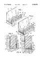
- FIGS. 5-7illustrate construction accessory 210, a third embodiment of panel support construction accessory 10 shown in FIGS. 1 and 2.
- FIG. 5is an assembled view of construction accessory 210.
- FIG. 6is an exploded view of construction accessory 210.
- FIG. 7is a sectional view of construction accessory 210 utilized in structure 12 including casing 190.
- construction accessory 210is similar to construction accessory 110 except that construction accessory 210 includes forward flange 286 in lieu of filter material 186.
- construction accessory 210may include forward flange 286 in addition to filter material 186.
- the remaining elements of construction accessory 210which correspond to similar elements of construction accessory 110 are numbered similarly.
- Forward flange 286extends between lower flange 180 and bottom flange 16 adjacent to cavity 188. Forward flange 286 extends opposite spacer 182 to enclose cavity 188. Forward flange 286 preferably includes a plurality of openings 292 that extend through forward flange 286 and communicate with cavity 188.
- openings 292extend generally perpendicular to perforations 34, openings 292 and perforations 34 enable moisture to escape from space 74 while reducing, if not completely eliminating, the possibility of wind-blown moisture entering space 74.
- openings 292may alternatively extend through portions of lower flange 180 in lieu of or in addition to extending through forward flange 286 to communicate with cavity 188 depending upon the configuration of construction accessory 210 as well as the configuration of structure 12 and casing 190.
- forward flange 286preferably has a vertical height greater than the vertical height or thickness of spacer 182 such that surface 300 of lower flange 180, which extends adjacent to cavity 188 below perforations 34, downwardly slopes away from back flange 14 and bottom flange 16 towards forward flange 286.
- spacer 182has a height or thickness extending between lower flange 180 and bottom flange 16 of about 0.050 inches while forward flange 286 has a vertical height of about 0.075 inches.
- forward flange 180is manufactured such that surface 300 has a natural gradient.
- lower flange 180may be formed from a deformable or flexible material such that the greater height of forward flange 286 as compared to the vertical height of spacer 182 causes surface 300 to deform or deflect sufficiently to cause surface 300 to have a downward slope. As shown by FIG. 7, the downwardly sloping surface 300 further facilities the flow of moisture through openings 292 and away from structure 12.
- FIG. 6best illustrates the preferred assembly of construction assembly of 210.
- construction accessory 210is preferably constructed from a first panel support component 296 and a second add-on component 298.
- Component 296includes back flange 14, bottom flange 16, side flange 18, support flange 20 and front flange 22.
- Component 298includes lower flange 180, spacer 182, drip leg 184 and forward flange 286.
- Lower flange 180 of component 298is configured for being coupled to component 296 so as to extend below bottom flange 16 and so as to provide surface 300 spaced from bottom flange 16 below perforations 34.
- spacer 182couples lower flange 180 to bottom flange 16 of component 296.
- components 296 and 298are preferably coupled together by welding.
- spacer 182 of component 298is positioned adjacent to the lower surface of bottom flange 16.
- Sufficiently heated pinsare positioned adjacent a top surface of bottom flange 16 and are further downwardly actuated to pierce bottom flange 16 and partially extend into spacer 182.
- the heated pinsmelt and fuse the materials of bottom flange 16 and spacer 182 together to securely couple component 296 to component 298.
- other fasteners or fastening methodsusing glue, adhesives, rivets, thermoplastics, thermosets, epoxies, mechanical interlocks and mechanical fasteners may be used to secure components 296 and 298 together.
- these alternative fasteners or fastening methodswill vary depending upon the type of materials from which components 296 and 298 are formed as well as the particular configuration of components 296 and 298.
- Components 296 and 298are preferably manufactured from extruded polyvinylchloride. Other manufacturing techniquest and materials may also be used. Perforations 34, perforations 46 and openings 292 are preferably formed using punching processes. As can be appreciated, the shape and size of perforations 34, perforations 46 and openings 292 may vary. Moreover, the manufacturing techniques used to form perforations 34, perforations 46 and openings 292 may also vary. As a result of this particular construction, component 298 may be easily and inexpensively manufactured. In addition, component 298 may be easily attached and added to existing panel support structures which have been modified to include perforations 34.
- component 298is illustrated as including spacer 182 and forward flange 286, spacer 182 and forward flange 286 may alternatively be formed as part of component 296 such that spacer 182 and forward flange 286 extend from a lower surface of bottom flange 16.
- FIG. 8is a sectional view illustrating construction accessory 310, a fourth embodiment of construction accessory 10.
- Construction accessory 310is identical to construction accessory 210 except that construction accessory 310 additionally includes side flange 312 obliquely extending from lower flange 180 below openings 292.
- Side flange 312supports drip leg 184 below and adjacent to casing 190.
- Side flange 312is preferably integrally extruded as part of component 298.
- side flange 312may be mounted or coupled to lower flange 180 by various fasteners or fastening methods.
- Side flange 312covers and protects casing 190. As indicated by arrows 393, 394, and 395, moisture within spacer 74 is effectively discharged away from casing 190.
Landscapes
- Engineering & Computer Science (AREA)
- Architecture (AREA)
- Civil Engineering (AREA)
- Structural Engineering (AREA)
- Physics & Mathematics (AREA)
- Acoustics & Sound (AREA)
- Electromagnetism (AREA)
- Building Environments (AREA)
- Finishing Walls (AREA)
Abstract
Description
Claims (66)
Priority Applications (4)
| Application Number | Priority Date | Filing Date | Title |
|---|---|---|---|
| US09/059,743US5946870A (en) | 1998-04-14 | 1998-04-14 | Panel support construction accessory |
| CA002259875ACA2259875A1 (en) | 1998-04-14 | 1999-01-22 | Panel support construction accessory |
| US09/305,631US6119429A (en) | 1998-04-14 | 1999-05-05 | Construction system and accessory |
| US09/558,761US6298609B1 (en) | 1998-04-14 | 2000-04-21 | Construction system with panel support accessory |
Applications Claiming Priority (1)
| Application Number | Priority Date | Filing Date | Title |
|---|---|---|---|
| US09/059,743US5946870A (en) | 1998-04-14 | 1998-04-14 | Panel support construction accessory |
Related Child Applications (1)
| Application Number | Title | Priority Date | Filing Date |
|---|---|---|---|
| US09/305,631ContinuationUS6119429A (en) | 1998-04-14 | 1999-05-05 | Construction system and accessory |
Publications (1)
| Publication Number | Publication Date |
|---|---|
| US5946870Atrue US5946870A (en) | 1999-09-07 |
Family
ID=22024944
Family Applications (2)
| Application Number | Title | Priority Date | Filing Date |
|---|---|---|---|
| US09/059,743Expired - LifetimeUS5946870A (en) | 1998-04-14 | 1998-04-14 | Panel support construction accessory |
| US09/305,631Expired - LifetimeUS6119429A (en) | 1998-04-14 | 1999-05-05 | Construction system and accessory |
Family Applications After (1)
| Application Number | Title | Priority Date | Filing Date |
|---|---|---|---|
| US09/305,631Expired - LifetimeUS6119429A (en) | 1998-04-14 | 1999-05-05 | Construction system and accessory |
Country Status (2)
| Country | Link |
|---|---|
| US (2) | US5946870A (en) |
| CA (1) | CA2259875A1 (en) |
Cited By (84)
| Publication number | Priority date | Publication date | Assignee | Title |
|---|---|---|---|---|
| US6470638B1 (en)* | 2000-08-24 | 2002-10-29 | Plastics Components, Inc. | Moisture management system |
| US6698144B1 (en)* | 2002-04-18 | 2004-03-02 | Plastic Components, Inc. | Stucco casing bead |
| US20040182037A1 (en)* | 2003-03-21 | 2004-09-23 | Tom Sourlis | Drainage system for use in masonry block construction |
| US20040231259A1 (en)* | 2003-05-21 | 2004-11-25 | Tom Sourlis | Drainage system for use in masonry block construction |
| US20040231261A1 (en)* | 2003-03-21 | 2004-11-25 | Mortar Net Uds, Ltd. | Drainage systems for use in masonry block construction |
| US20050005576A1 (en)* | 2003-07-07 | 2005-01-13 | Ruston Wilbur R. | Liquid impervious apparatus for wallboard |
| US20050138876A1 (en)* | 2003-05-21 | 2005-06-30 | Tom Sourlis | Drainage system for use in masonry block construction |
| US20050166471A1 (en)* | 2004-01-07 | 2005-08-04 | Allen L. R. | Flashings for windows and the like |
| US20050284339A1 (en)* | 2001-04-03 | 2005-12-29 | Greg Brunton | Durable building article and method of making same |
| WO2006039762A1 (en)* | 2004-10-14 | 2006-04-20 | James Hardie International Finance B.V. | Cavity wall system |
| US20060150553A1 (en)* | 2005-01-13 | 2006-07-13 | Erenio Reyes | Control joint |
| US20070062137A1 (en)* | 2005-09-16 | 2007-03-22 | Vinyl Corp. | Screed joints |
| US20070130861A1 (en)* | 2005-12-02 | 2007-06-14 | Gary Chenier | Movement control screed |
| US20080229676A1 (en)* | 2007-03-20 | 2008-09-25 | Allen L Ross | Sill Flashing and Associated Method |
| US20090007499A1 (en)* | 2006-01-12 | 2009-01-08 | Flashman Flashing Systems Limited | Cavity Head Flashing |
| US20090056241A1 (en)* | 2007-08-28 | 2009-03-05 | Juergen Koessler | Moisture management systems and methods for building openings |
| US7524555B2 (en) | 1999-11-19 | 2009-04-28 | James Hardie International Finance B.V. | Pre-finished and durable building material |
| US20090173858A1 (en)* | 2008-01-08 | 2009-07-09 | Lacerte Marc D | Board mount |
| US20090183453A1 (en)* | 2008-01-21 | 2009-07-23 | Juergen Koessler | Apparatus for providing air flow in a building wall |
| US20090205281A1 (en)* | 2005-01-05 | 2009-08-20 | Novabrik International Inc. | Starter element for stackable inter-engaging bricks |
| US20100101168A1 (en)* | 2008-10-27 | 2010-04-29 | Mitek Holdings, Inc. | Molded polymeric drip edge |
| US7713615B2 (en) | 2001-04-03 | 2010-05-11 | James Hardie International Finance B.V. | Reinforced fiber cement article and methods of making and installing the same |
| US20100287862A1 (en)* | 2009-05-18 | 2010-11-18 | Moisture Management, Llc | Exterior wall assembly including dynamic moisture removal feature |
| US20100287861A1 (en)* | 2009-05-18 | 2010-11-18 | Moisture Management, Llc | Exterior wall assembly including moisture transportation feature |
| US20110162292A1 (en)* | 2007-07-24 | 2011-07-07 | Lrm Industries, Llc | Enclosed structure |
| US7993570B2 (en) | 2002-10-07 | 2011-08-09 | James Hardie Technology Limited | Durable medium-density fibre cement composite |
| US7998571B2 (en) | 2004-07-09 | 2011-08-16 | James Hardie Technology Limited | Composite cement article incorporating a powder coating and methods of making same |
| US20120110936A1 (en)* | 2010-11-08 | 2012-05-10 | Egan William F | Trim bead and stucco system including same |
| US8281535B2 (en) | 2002-07-16 | 2012-10-09 | James Hardie Technology Limited | Packaging prefinished fiber cement articles |
| US8297018B2 (en) | 2002-07-16 | 2012-10-30 | James Hardie Technology Limited | Packaging prefinished fiber cement products |
| US20120324814A1 (en)* | 2011-06-21 | 2012-12-27 | Victor Amend | Exterior wall finishing arrangement |
| US8528265B1 (en)* | 2010-02-18 | 2013-09-10 | Innovations & Ideas, Llc | Laminate system |
| US20130318901A1 (en)* | 2011-02-21 | 2013-12-05 | Siniat International Sas | Element Resistant to Air Transfers and Thermal and Hydric Transfers in the Field of Construction, Especially for Lightweight Walls or Lightweight Facades |
| USD699013S1 (en)* | 2013-06-20 | 2014-02-04 | Blanco Gmbh + Co Kg | Sink accessory |
| US20140041316A1 (en)* | 2012-08-10 | 2014-02-13 | Steven A. Norwood | Prefabricated Flashing Product |
| USD703307S1 (en) | 2012-08-10 | 2014-04-22 | Basf Corporation | Trim bead for a building wall |
| USD703306S1 (en) | 2012-08-10 | 2014-04-22 | Basf Corporation | Trim bead for building wall |
| US8813443B2 (en) | 2009-05-18 | 2014-08-26 | Moisture Management, Llc | Building envelope assembly including moisture transportation feature |
| USD714969S1 (en) | 2012-08-10 | 2014-10-07 | Norwood Architecture, Inc. | Window flashing product |
| US8869491B2 (en) | 2010-11-08 | 2014-10-28 | Basf Corporation | Trim bead and stucco system including same |
| US8993462B2 (en) | 2006-04-12 | 2015-03-31 | James Hardie Technology Limited | Surface sealed reinforced building element |
| USD761971S1 (en)* | 2015-05-22 | 2016-07-19 | Clarkwestern Dietrich Building Systems Llc | Casing bead with backing strip |
| USD762310S1 (en)* | 2015-05-22 | 2016-07-26 | Clarkwestern Dietrich Building Systems Llc | Casing bead with removable leg |
| DE102015104978A1 (en)* | 2015-03-31 | 2016-10-06 | Marius Frenzer | Profile system for assembly with components |
| USD792609S1 (en)* | 2015-08-28 | 2017-07-18 | Clarkwestern Dietrich Building Systems Llc | Casing bead with metal lath attachment feature |
| USD792610S1 (en)* | 2015-08-28 | 2017-07-18 | Clarkwestern Dietrich Building Systems Llc | Control joint with metal lath attachment feature |
| US9745789B2 (en) | 2012-08-10 | 2017-08-29 | Norwood Architecture, Inc. | Prefabricated flashing product |
| US9745790B2 (en) | 2012-08-10 | 2017-08-29 | Norwood Architecture, Inc. | Prefabricated flashing product |
| USD800345S1 (en)* | 2016-02-05 | 2017-10-17 | Clarkwestern Dietrich Building Systems | Channel reveal with ribbed flanges |
| USD800346S1 (en) | 2016-02-05 | 2017-10-17 | Clarkwestern Dietrich Building Systems Llc | Control joint with ribbed flanges |
| USD800344S1 (en) | 2016-02-05 | 2017-10-17 | Clarkwestern Dietrich Building Systems Llc | Casing bead with a ribbed flange |
| USD800921S1 (en) | 2016-02-05 | 2017-10-24 | Clarkwestern Dietrich Building Systems Llc | Framing accessory with a ribbed flange |
| US20170306620A1 (en)* | 2016-04-22 | 2017-10-26 | Jimmy Keith Yeary, JR. | Building rail system |
| US9963875B1 (en)* | 2017-02-24 | 2018-05-08 | Breghtway Construction Solutions, LLC | Exterior wall cladding system for buildings |
| US10072414B2 (en)* | 2015-05-08 | 2018-09-11 | Thermo-Clad Technologies, Inc. | Insulative building panels |
| US10100530B1 (en)* | 2017-07-20 | 2018-10-16 | Robert A. Clark | Method and apparatus for construction of exterior wall system |
| US10161179B2 (en) | 2015-11-13 | 2018-12-25 | Norwood Architecture, Inc. | Three-dimensional prefabricated flashing scaffolding system |
| USD839454S1 (en)* | 2017-04-24 | 2019-01-29 | Robert ZIEGAN | Grid edging |
| US10196812B1 (en)* | 2015-09-29 | 2019-02-05 | Frank L. Duffy | Weep screed |
| USD841833S1 (en) | 2017-01-09 | 2019-02-26 | Clarkwestern Dietrich Building Systems Llc | Channel reveal with ribbed and perforated flanges |
| USD842497S1 (en) | 2017-01-09 | 2019-03-05 | Clarkwestern Dietrich Building Systems Llc | Control joint with ribbed and perforated flanges |
| USD842496S1 (en) | 2017-01-09 | 2019-03-05 | Clarkwestern Dietrich Building Systems Llc | Casing bead with a ribbed and perforated flange |
| USD843015S1 (en) | 2017-01-09 | 2019-03-12 | Clarkwestern Dietrich Building Systems Llc | Framing accessory with a ribbed and perforated flange |
| JP2019123064A (en)* | 2018-01-19 | 2019-07-25 | フクビ化学工業株式会社 | Manufacturing method and opening formation method of resin extrusion molding |
| USD861196S1 (en) | 2017-03-15 | 2019-09-24 | Clarkwestern Dietrich Building Systems Llc | Drip flange with backing strip |
| US10494818B2 (en) | 2016-10-25 | 2019-12-03 | E-Z Bead, Llc | Vented stop bead apparatus, vented weep screed apparatus, and related systems and methods thereof |
| US10648184B2 (en) | 2017-09-22 | 2020-05-12 | E-Z Bead, Llc | Stop bead for panel-based siding, and related methods and systems |
| US10662607B2 (en)* | 2018-08-21 | 2020-05-26 | Jesse B. Trebil | Water drainage edging |
| US10697132B2 (en) | 2017-05-16 | 2020-06-30 | Robert ZIEGAN | Surface system and method of installation |
| USD904649S1 (en) | 2019-09-25 | 2020-12-08 | Clarkwestern Dietrich Building Systems Llc | Weep screed |
| US11091921B2 (en) | 2017-09-22 | 2021-08-17 | E-Z Bead, Llc | Stop bead for panel-based siding, and related methods and systems |
| US11180922B2 (en) | 2019-12-13 | 2021-11-23 | E-Z Bead, Llc | Bead stop for a wall having in interior cement board layer |
| US11332925B2 (en) | 2018-05-31 | 2022-05-17 | Moisture Management, Llc | Drain assembly including moisture transportation feature |
| US20220325529A1 (en)* | 2021-04-13 | 2022-10-13 | Grandview Ea Building Systems Corp. | Pressure equalized rainscreen systems and methods |
| US11486150B2 (en) | 2016-12-20 | 2022-11-01 | Clarkwestern Dietrich Building Systems Llc | Finishing accessory with backing strip |
| US11492809B1 (en)* | 2018-08-10 | 2022-11-08 | Randle Bros. Developing, LLC | Building sheathing protecting bracket |
| US20220389747A1 (en)* | 2021-06-07 | 2022-12-08 | Wesley Greene | Baffled watertight building opening assembly extension |
| US11613889B2 (en)* | 2019-10-04 | 2023-03-28 | Innovations & Ideas, Llc | Weeping control joint system |
| US11629503B2 (en) | 2019-12-13 | 2023-04-18 | E-Z Bead, Llc | Bead stop for a wall having interior cement board layer |
| US11885138B2 (en) | 2020-11-12 | 2024-01-30 | Clarkwestern Dietrich Building Systems Llc | Control joint |
| USD1025407S1 (en)* | 2021-10-05 | 2024-04-30 | Bott GmbH & Co. KG | Perforated panel |
| USD1026252S1 (en) | 2020-11-12 | 2024-05-07 | Clarkwestern Dietrich Building Systems Llc | Control joint |
| US12006704B1 (en)* | 2020-06-29 | 2024-06-11 | Plastic Components, Inc. | Casing bead |
| USD1035046S1 (en)* | 2021-05-18 | 2024-07-09 | Bott GmbH & Co. KG | Perforated panel for frame end |
Families Citing this family (26)
| Publication number | Priority date | Publication date | Assignee | Title |
|---|---|---|---|---|
| US6321491B1 (en)* | 1999-01-15 | 2001-11-27 | Ronald F. DiMauro | Bulkhead door seal |
| US7562504B2 (en) | 2000-05-30 | 2009-07-21 | Wmh Consulting, Inc. | Architectural panel fabrication system |
| US6591559B2 (en)* | 2001-04-03 | 2003-07-15 | Victor Contreras | Exterior wall sealing system |
| US7621079B2 (en)* | 2005-01-14 | 2009-11-24 | Fukuvi Usa, Inc. | Water drainage component |
| US20060179747A1 (en)* | 2005-02-09 | 2006-08-17 | Creech Claude S | Method and apparatus for integral modular masonry flashing |
| US20100132288A1 (en)* | 2008-12-01 | 2010-06-03 | Hines David C | Top Sided Vented Trim for Exterior Cladding System |
| WO2011051818A2 (en)* | 2009-10-29 | 2011-05-05 | James Hardie Technology Limited | Undercladding insulation and cladding support systems and to wall structures using the same |
| US8695302B2 (en) | 2012-03-22 | 2014-04-15 | Owens Corning Intellectual Capital, Llc | Air seal assembly |
| WO2016040273A1 (en)* | 2014-09-09 | 2016-03-17 | Sto Corp. | Casing accessories |
| DE102015003308A1 (en)* | 2015-03-13 | 2016-09-15 | Daw Se | End bar and method for mounting a end bar |
| US10060126B2 (en)* | 2016-02-09 | 2018-08-28 | Ty-Das Building Products, Llc | Starter strip |
| US10024063B2 (en) | 2016-03-01 | 2018-07-17 | Denis P. Friel | Weep screed |
| US10533324B2 (en) | 2017-11-30 | 2020-01-14 | Alabama Metal Industries Corporation | Below top of wall ventilation screed device and assembly |
| US11180913B2 (en) | 2017-11-30 | 2021-11-23 | Alabama Metal Industries Corporation | Top of wall ventilation screed device and assembly |
| US10669721B2 (en) | 2017-12-18 | 2020-06-02 | Alabama Metal Industries Corporation | Flashing device assembly |
| US10731335B2 (en) | 2018-08-03 | 2020-08-04 | Alabama Metal Industries Corporation | Top of wall ventilation screed device and assembly |
| US10870995B1 (en)* | 2018-11-13 | 2020-12-22 | Robert B. Jordan, IV | Lower edge finish for drywall |
| US10753083B2 (en) | 2018-11-19 | 2020-08-25 | Alabama Metal Industries Corporation | Below top of wall ventilation screed device and assembly |
| USD923821S1 (en) | 2018-11-27 | 2021-06-29 | Alabama Metal Industries Corporation | Top of wall ventilation screed device |
| USD940349S1 (en) | 2018-11-27 | 2022-01-04 | Alabama Metal Industries Corporation | Below top of wall ventilation screed device |
| USD940350S1 (en) | 2019-07-11 | 2022-01-04 | Alabama Metal Industries Corporation | Vented finish bead |
| USD979099S1 (en) | 2019-08-22 | 2023-02-21 | Alabama Metal Industries Corporation | Ventilation screed device |
| USD973912S1 (en) | 2019-08-30 | 2022-12-27 | Alabama Metal Industries Corporation | Ventilation screed device |
| US11365548B1 (en)* | 2020-08-17 | 2022-06-21 | Robert B. Jordan, IV | Lower edge finish for drywall with installation aids |
| USD1033680S1 (en) | 2020-11-13 | 2024-07-02 | Alabama Metal Industries Corporation | Self-adhering bead device |
| US20220298782A1 (en)* | 2021-03-22 | 2022-09-22 | John H. Koester | Termination for building structures |
Citations (21)
| Publication number | Priority date | Publication date | Assignee | Title |
|---|---|---|---|---|
| US1310331A (en)* | 1919-07-15 | William e | ||
| US2073185A (en)* | 1936-01-03 | 1937-03-09 | American Rolling Mill Co | Channel structure for metal arches |
| US2483888A (en)* | 1944-08-03 | 1949-10-04 | Gideon R Danielson | Edge finishing strip for plaster walls |
| US3019866A (en)* | 1956-09-03 | 1962-02-06 | Metriframe Structures Ltd | Members for use in the construction of structural framework |
| US3332180A (en)* | 1965-04-20 | 1967-07-25 | Nat Homes Corp | Gable and trim construction |
| US3494085A (en)* | 1968-01-29 | 1970-02-10 | Joseph Van Bael | Recessed stop bead |
| US3509674A (en)* | 1966-05-13 | 1970-05-05 | Herbert L Birum Jr | Exterior wall accessories |
| US4059936A (en)* | 1976-09-27 | 1977-11-29 | Insuldeck Corporation | Panel construction for roofs and the like |
| US4624087A (en)* | 1984-11-28 | 1986-11-25 | National Gypsum Company | Drywall exterior corner bead |
| US4722153A (en)* | 1985-01-30 | 1988-02-02 | Eighteenth Yeneb Pty. Ltd. | Cover joints for masonry and sheet material structures |
| US4752517A (en)* | 1986-10-02 | 1988-06-21 | Otto Fastening Systems, Ltd. | Method of interconnecting a panel edge member to panel portions |
| US5003743A (en)* | 1990-03-30 | 1991-04-02 | Vinyl Corporation | Panel support member and support arrangement |
| US5226274A (en)* | 1989-02-22 | 1993-07-13 | Michael Sommerstein | Panel mounting clip |
| US5272846A (en)* | 1990-06-04 | 1993-12-28 | W. P. Hickman Company | Roof edge anchoring devices for foam roofing |
| US5397201A (en)* | 1992-12-22 | 1995-03-14 | Aluminum Company Of America | Wall assembly for offshore use |
| US5414965A (en)* | 1992-04-15 | 1995-05-16 | W. P. Hickman Company | Roof edge anchoring devices for building structures |
| US5433986A (en)* | 1994-02-14 | 1995-07-18 | Moscatello; David | Combination slutter and nosing strip |
| US5519969A (en)* | 1991-08-19 | 1996-05-28 | Golba; Thomas R. | Removable roof flashing cover system |
| US5531050A (en)* | 1994-04-28 | 1996-07-02 | Stibolt; Paul E. | Drywall corner finishing device |
| US5729939A (en)* | 1996-06-18 | 1998-03-24 | Di Benedetto; Frank | Steel anchor bracket for surface mount on a concrete wall |
| US5784838A (en)* | 1997-03-28 | 1998-07-28 | Phillips; Jeffery L. | Drain for draining water from a basement floor |
Family Cites Families (18)
| Publication number | Priority date | Publication date | Assignee | Title |
|---|---|---|---|---|
| US2645824A (en)* | 1949-09-13 | 1953-07-21 | Edwin J Titsworth | Ventilated wall |
| US2703002A (en)* | 1952-02-04 | 1955-03-01 | Philip A Suskind | Baseboard drain construction |
| US2905072A (en)* | 1957-10-21 | 1959-09-22 | Anthony C Oswald | Wall ventilator |
| US3239977A (en)* | 1964-03-05 | 1966-03-15 | Shore Harry | Wall construction and moisture barrier |
| US3314201A (en)* | 1964-11-23 | 1967-04-18 | Ador Corp | Weep hole construction for windows and the like |
| US3471982A (en)* | 1967-05-12 | 1969-10-14 | Conrad A Strozewski | Soffit adapters |
| US3485001A (en)* | 1967-12-06 | 1969-12-23 | Peter H Miller | Edging strip for a dry wall structure |
| US3638372A (en)* | 1969-07-02 | 1972-02-01 | Carl Rosenthal | Window sash rebate profile with a condensate reception gutter |
| US4075800A (en)* | 1977-02-09 | 1978-02-28 | Medea Molick | Foundation aquaduct and expansion joint |
| US4621470A (en)* | 1984-04-02 | 1986-11-11 | United States Gypsum Company | Runner and area separation wall structure utilizing runner |
| US4622791A (en)* | 1985-03-21 | 1986-11-18 | Masonite Corporation | Base molding |
| US4691487A (en)* | 1986-07-31 | 1987-09-08 | Gerald Kessler | Drain tube for windows |
| US5022212A (en)* | 1989-08-28 | 1991-06-11 | Thomas Lippolt | Molding structure |
| US4947593A (en)* | 1989-09-19 | 1990-08-14 | Kuo Pang | Ventilable curtain wall linked by ventilating couplers |
| US4984402A (en)* | 1989-09-29 | 1991-01-15 | Omniglass Ltd. | Sash window arrangement |
| US5718086A (en)* | 1996-06-10 | 1998-02-17 | Dunn; George A. | Method and apparatus for continuous soffit venting |
| US5918427A (en)* | 1996-10-04 | 1999-07-06 | Vanderwerf; Pieter A. | Termite shield for permeable sheathing |
| US5836135A (en)* | 1997-01-31 | 1998-11-17 | Hagan; Joseph R. | Drainage track |
- 1998
- 1998-04-14USUS09/059,743patent/US5946870A/ennot_activeExpired - Lifetime
- 1999
- 1999-01-22CACA002259875Apatent/CA2259875A1/ennot_activeAbandoned
- 1999-05-05USUS09/305,631patent/US6119429A/ennot_activeExpired - Lifetime
Patent Citations (21)
| Publication number | Priority date | Publication date | Assignee | Title |
|---|---|---|---|---|
| US1310331A (en)* | 1919-07-15 | William e | ||
| US2073185A (en)* | 1936-01-03 | 1937-03-09 | American Rolling Mill Co | Channel structure for metal arches |
| US2483888A (en)* | 1944-08-03 | 1949-10-04 | Gideon R Danielson | Edge finishing strip for plaster walls |
| US3019866A (en)* | 1956-09-03 | 1962-02-06 | Metriframe Structures Ltd | Members for use in the construction of structural framework |
| US3332180A (en)* | 1965-04-20 | 1967-07-25 | Nat Homes Corp | Gable and trim construction |
| US3509674A (en)* | 1966-05-13 | 1970-05-05 | Herbert L Birum Jr | Exterior wall accessories |
| US3494085A (en)* | 1968-01-29 | 1970-02-10 | Joseph Van Bael | Recessed stop bead |
| US4059936A (en)* | 1976-09-27 | 1977-11-29 | Insuldeck Corporation | Panel construction for roofs and the like |
| US4624087A (en)* | 1984-11-28 | 1986-11-25 | National Gypsum Company | Drywall exterior corner bead |
| US4722153A (en)* | 1985-01-30 | 1988-02-02 | Eighteenth Yeneb Pty. Ltd. | Cover joints for masonry and sheet material structures |
| US4752517A (en)* | 1986-10-02 | 1988-06-21 | Otto Fastening Systems, Ltd. | Method of interconnecting a panel edge member to panel portions |
| US5226274A (en)* | 1989-02-22 | 1993-07-13 | Michael Sommerstein | Panel mounting clip |
| US5003743A (en)* | 1990-03-30 | 1991-04-02 | Vinyl Corporation | Panel support member and support arrangement |
| US5272846A (en)* | 1990-06-04 | 1993-12-28 | W. P. Hickman Company | Roof edge anchoring devices for foam roofing |
| US5519969A (en)* | 1991-08-19 | 1996-05-28 | Golba; Thomas R. | Removable roof flashing cover system |
| US5414965A (en)* | 1992-04-15 | 1995-05-16 | W. P. Hickman Company | Roof edge anchoring devices for building structures |
| US5397201A (en)* | 1992-12-22 | 1995-03-14 | Aluminum Company Of America | Wall assembly for offshore use |
| US5433986A (en)* | 1994-02-14 | 1995-07-18 | Moscatello; David | Combination slutter and nosing strip |
| US5531050A (en)* | 1994-04-28 | 1996-07-02 | Stibolt; Paul E. | Drywall corner finishing device |
| US5729939A (en)* | 1996-06-18 | 1998-03-24 | Di Benedetto; Frank | Steel anchor bracket for surface mount on a concrete wall |
| US5784838A (en)* | 1997-03-28 | 1998-07-28 | Phillips; Jeffery L. | Drain for draining water from a basement floor |
Non-Patent Citations (4)
| Title |
|---|
| "Vinyl Corp. Product Data" Catalog; copyright 1997. |
| "VinylTech Plastic Components, Inc."; Excerpts from Catalog; 8 pages. |
| Vinyl Corp. Product Data Catalog; copyright 1997.* |
| VinylTech Plastic Components, Inc. ; Excerpts from Catalog; 8 pages.* |
Cited By (124)
| Publication number | Priority date | Publication date | Assignee | Title |
|---|---|---|---|---|
| US7524555B2 (en) | 1999-11-19 | 2009-04-28 | James Hardie International Finance B.V. | Pre-finished and durable building material |
| US6470638B1 (en)* | 2000-08-24 | 2002-10-29 | Plastics Components, Inc. | Moisture management system |
| US7713615B2 (en) | 2001-04-03 | 2010-05-11 | James Hardie International Finance B.V. | Reinforced fiber cement article and methods of making and installing the same |
| US20050284339A1 (en)* | 2001-04-03 | 2005-12-29 | Greg Brunton | Durable building article and method of making same |
| US8409380B2 (en) | 2001-04-03 | 2013-04-02 | James Hardie Technology Limited | Reinforced fiber cement article and methods of making and installing the same |
| US6698144B1 (en)* | 2002-04-18 | 2004-03-02 | Plastic Components, Inc. | Stucco casing bead |
| US8281535B2 (en) | 2002-07-16 | 2012-10-09 | James Hardie Technology Limited | Packaging prefinished fiber cement articles |
| US8297018B2 (en) | 2002-07-16 | 2012-10-30 | James Hardie Technology Limited | Packaging prefinished fiber cement products |
| US7993570B2 (en) | 2002-10-07 | 2011-08-09 | James Hardie Technology Limited | Durable medium-density fibre cement composite |
| US7726084B2 (en) | 2003-03-21 | 2010-06-01 | Tom Sourlis | Drainage systems for use in masonry block construction |
| US20040182037A1 (en)* | 2003-03-21 | 2004-09-23 | Tom Sourlis | Drainage system for use in masonry block construction |
| US20040231261A1 (en)* | 2003-03-21 | 2004-11-25 | Mortar Net Uds, Ltd. | Drainage systems for use in masonry block construction |
| US7216460B2 (en) | 2003-03-21 | 2007-05-15 | Tom Sourlis | Drainage system for use in masonry block construction |
| US20040231259A1 (en)* | 2003-05-21 | 2004-11-25 | Tom Sourlis | Drainage system for use in masonry block construction |
| US6912820B2 (en) | 2003-05-21 | 2005-07-05 | Tom Sourlis | Drainage system for use in masonry block construction |
| US20050138876A1 (en)* | 2003-05-21 | 2005-06-30 | Tom Sourlis | Drainage system for use in masonry block construction |
| US7448175B2 (en) | 2003-05-21 | 2008-11-11 | Tom Sourlis | Drainage system for use in masonry block construction |
| US20050005576A1 (en)* | 2003-07-07 | 2005-01-13 | Ruston Wilbur R. | Liquid impervious apparatus for wallboard |
| US7059087B2 (en)* | 2004-01-07 | 2006-06-13 | Allen L Ross | Corner flashing for windows and the like |
| US7290379B2 (en) | 2004-01-07 | 2007-11-06 | Allen L Ross | Corner flashing for windows and the like |
| US20060168902A1 (en)* | 2004-01-07 | 2006-08-03 | Allen L R | Corner Flashing for Windows and the Like |
| US20050166470A1 (en)* | 2004-01-07 | 2005-08-04 | Allen L. R. | Corner flashing for windows and the like |
| US20050166471A1 (en)* | 2004-01-07 | 2005-08-04 | Allen L. R. | Flashings for windows and the like |
| US7998571B2 (en) | 2004-07-09 | 2011-08-16 | James Hardie Technology Limited | Composite cement article incorporating a powder coating and methods of making same |
| WO2006039762A1 (en)* | 2004-10-14 | 2006-04-20 | James Hardie International Finance B.V. | Cavity wall system |
| US20090205281A1 (en)* | 2005-01-05 | 2009-08-20 | Novabrik International Inc. | Starter element for stackable inter-engaging bricks |
| US8281530B2 (en)* | 2005-01-05 | 2012-10-09 | Novabrik International Inc. | Starter element for stackable inter-engaging bricks |
| US20060150553A1 (en)* | 2005-01-13 | 2006-07-13 | Erenio Reyes | Control joint |
| US7757450B2 (en) | 2005-01-13 | 2010-07-20 | Dietrich Industries, Inc. | Control joint |
| US20070062137A1 (en)* | 2005-09-16 | 2007-03-22 | Vinyl Corp. | Screed joints |
| US20070130861A1 (en)* | 2005-12-02 | 2007-06-14 | Gary Chenier | Movement control screed |
| US8584416B2 (en) | 2005-12-02 | 2013-11-19 | Alabama Metal Industries Corporation | Movement control screed |
| US20090007499A1 (en)* | 2006-01-12 | 2009-01-08 | Flashman Flashing Systems Limited | Cavity Head Flashing |
| US8993462B2 (en) | 2006-04-12 | 2015-03-31 | James Hardie Technology Limited | Surface sealed reinforced building element |
| US20080229676A1 (en)* | 2007-03-20 | 2008-09-25 | Allen L Ross | Sill Flashing and Associated Method |
| US7775004B2 (en) | 2007-03-20 | 2010-08-17 | Allen L Ross | Sill flashing and associated method |
| US20110162292A1 (en)* | 2007-07-24 | 2011-07-07 | Lrm Industries, Llc | Enclosed structure |
| US8156690B2 (en)* | 2007-07-24 | 2012-04-17 | Lrm Industries International, Inc. | Enclosed structure |
| US20090056241A1 (en)* | 2007-08-28 | 2009-03-05 | Juergen Koessler | Moisture management systems and methods for building openings |
| US8752800B2 (en) | 2008-01-08 | 2014-06-17 | Board Mount Inc. | Board mount |
| US8733721B2 (en) | 2008-01-08 | 2014-05-27 | Board Mount Inc. | Board mount |
| US20090173858A1 (en)* | 2008-01-08 | 2009-07-09 | Lacerte Marc D | Board mount |
| US20090183453A1 (en)* | 2008-01-21 | 2009-07-23 | Juergen Koessler | Apparatus for providing air flow in a building wall |
| USD648865S1 (en) | 2008-10-27 | 2011-11-15 | Mitek Holdings, Inc. | Molded polymeric drip edge |
| US20100101168A1 (en)* | 2008-10-27 | 2010-04-29 | Mitek Holdings, Inc. | Molded polymeric drip edge |
| US20140360109A1 (en)* | 2009-05-18 | 2014-12-11 | Moisture Management, Llc | Building envelope assembly including moisture transportation feature |
| US8813443B2 (en) | 2009-05-18 | 2014-08-26 | Moisture Management, Llc | Building envelope assembly including moisture transportation feature |
| US8316597B2 (en) | 2009-05-18 | 2012-11-27 | Moisture Management, Llc | Method of removing moisture from a wall assembly |
| US20100287861A1 (en)* | 2009-05-18 | 2010-11-18 | Moisture Management, Llc | Exterior wall assembly including moisture transportation feature |
| US9353498B2 (en)* | 2009-05-18 | 2016-05-31 | Moisture Management, Llc | Building envelope assembly including moisture transportation feature |
| US20100287862A1 (en)* | 2009-05-18 | 2010-11-18 | Moisture Management, Llc | Exterior wall assembly including dynamic moisture removal feature |
| US8074409B2 (en)* | 2009-05-18 | 2011-12-13 | Moisture Management, Llc | Exterior wall assembly including moisture removal feature |
| US8001736B2 (en)* | 2009-05-18 | 2011-08-23 | Moisture Management, Llc | Exterior wall assembly including moisture transportation feature |
| US8528265B1 (en)* | 2010-02-18 | 2013-09-10 | Innovations & Ideas, Llc | Laminate system |
| US8869491B2 (en) | 2010-11-08 | 2014-10-28 | Basf Corporation | Trim bead and stucco system including same |
| US20120110936A1 (en)* | 2010-11-08 | 2012-05-10 | Egan William F | Trim bead and stucco system including same |
| US9200454B2 (en) | 2010-11-08 | 2015-12-01 | Basf Corporation | Trim bead and stucco system including same |
| US20130318901A1 (en)* | 2011-02-21 | 2013-12-05 | Siniat International Sas | Element Resistant to Air Transfers and Thermal and Hydric Transfers in the Field of Construction, Especially for Lightweight Walls or Lightweight Facades |
| US8555581B2 (en)* | 2011-06-21 | 2013-10-15 | Victor Amend | Exterior wall finishing arrangement |
| US20120324814A1 (en)* | 2011-06-21 | 2012-12-27 | Victor Amend | Exterior wall finishing arrangement |
| US8959842B2 (en)* | 2012-08-10 | 2015-02-24 | Norwood Architecture, Inc. | Prefabricated flashing product |
| US9745789B2 (en) | 2012-08-10 | 2017-08-29 | Norwood Architecture, Inc. | Prefabricated flashing product |
| US9909352B2 (en) | 2012-08-10 | 2018-03-06 | Norwood Architecture, Inc. | Prefabricated flashing product |
| USD703306S1 (en) | 2012-08-10 | 2014-04-22 | Basf Corporation | Trim bead for building wall |
| US9194171B2 (en) | 2012-08-10 | 2015-11-24 | Norwood Architecture, Inc. | Prefabricated flashing product |
| USD703307S1 (en) | 2012-08-10 | 2014-04-22 | Basf Corporation | Trim bead for a building wall |
| USD748826S1 (en) | 2012-08-10 | 2016-02-02 | Norwood Architecture, Inc. | Window flashing product |
| US20140041316A1 (en)* | 2012-08-10 | 2014-02-13 | Steven A. Norwood | Prefabricated Flashing Product |
| US11560748B2 (en) | 2012-08-10 | 2023-01-24 | Norwood Architecture, Inc. | Prefabricated flashing product |
| US9771753B2 (en) | 2012-08-10 | 2017-09-26 | Norwood Architecture, Inc. | Prefabricated flashing product |
| US9745790B2 (en) | 2012-08-10 | 2017-08-29 | Norwood Architecture, Inc. | Prefabricated flashing product |
| USD714969S1 (en) | 2012-08-10 | 2014-10-07 | Norwood Architecture, Inc. | Window flashing product |
| USD699013S1 (en)* | 2013-06-20 | 2014-02-04 | Blanco Gmbh + Co Kg | Sink accessory |
| DE102015104978A1 (en)* | 2015-03-31 | 2016-10-06 | Marius Frenzer | Profile system for assembly with components |
| US10072414B2 (en)* | 2015-05-08 | 2018-09-11 | Thermo-Clad Technologies, Inc. | Insulative building panels |
| USD762310S1 (en)* | 2015-05-22 | 2016-07-26 | Clarkwestern Dietrich Building Systems Llc | Casing bead with removable leg |
| USD761971S1 (en)* | 2015-05-22 | 2016-07-19 | Clarkwestern Dietrich Building Systems Llc | Casing bead with backing strip |
| USD792610S1 (en)* | 2015-08-28 | 2017-07-18 | Clarkwestern Dietrich Building Systems Llc | Control joint with metal lath attachment feature |
| USD792609S1 (en)* | 2015-08-28 | 2017-07-18 | Clarkwestern Dietrich Building Systems Llc | Casing bead with metal lath attachment feature |
| US10196812B1 (en)* | 2015-09-29 | 2019-02-05 | Frank L. Duffy | Weep screed |
| US10161179B2 (en) | 2015-11-13 | 2018-12-25 | Norwood Architecture, Inc. | Three-dimensional prefabricated flashing scaffolding system |
| US10501980B2 (en) | 2015-11-13 | 2019-12-10 | Norwood Architecture, Inc. | Three-dimensional prefabricated flashing scaffolding system |
| USD800921S1 (en) | 2016-02-05 | 2017-10-24 | Clarkwestern Dietrich Building Systems Llc | Framing accessory with a ribbed flange |
| USD800344S1 (en) | 2016-02-05 | 2017-10-17 | Clarkwestern Dietrich Building Systems Llc | Casing bead with a ribbed flange |
| USD800345S1 (en)* | 2016-02-05 | 2017-10-17 | Clarkwestern Dietrich Building Systems | Channel reveal with ribbed flanges |
| USD800346S1 (en) | 2016-02-05 | 2017-10-17 | Clarkwestern Dietrich Building Systems Llc | Control joint with ribbed flanges |
| US10844609B2 (en)* | 2016-04-22 | 2020-11-24 | Jimmy Keith Yeary, JR. | Building rail system |
| US20170306620A1 (en)* | 2016-04-22 | 2017-10-26 | Jimmy Keith Yeary, JR. | Building rail system |
| US10494818B2 (en) | 2016-10-25 | 2019-12-03 | E-Z Bead, Llc | Vented stop bead apparatus, vented weep screed apparatus, and related systems and methods thereof |
| US12018496B2 (en) | 2016-12-20 | 2024-06-25 | Clarkwestern Dietrich Building Systems Llc | Finishing accessory with backing strip |
| US11725401B2 (en) | 2016-12-20 | 2023-08-15 | Clarkwestern Dietrich Building Systems Llc | Finishing accessory with backing strip |
| US11486150B2 (en) | 2016-12-20 | 2022-11-01 | Clarkwestern Dietrich Building Systems Llc | Finishing accessory with backing strip |
| USD843015S1 (en) | 2017-01-09 | 2019-03-12 | Clarkwestern Dietrich Building Systems Llc | Framing accessory with a ribbed and perforated flange |
| USD842497S1 (en) | 2017-01-09 | 2019-03-05 | Clarkwestern Dietrich Building Systems Llc | Control joint with ribbed and perforated flanges |
| USD842496S1 (en) | 2017-01-09 | 2019-03-05 | Clarkwestern Dietrich Building Systems Llc | Casing bead with a ribbed and perforated flange |
| USD841833S1 (en) | 2017-01-09 | 2019-02-26 | Clarkwestern Dietrich Building Systems Llc | Channel reveal with ribbed and perforated flanges |
| US20190271156A1 (en)* | 2017-02-24 | 2019-09-05 | Breghtway Construction Solutions, LLC | Insulating Panel for Stucco Exterior |
| US10294667B2 (en)* | 2017-02-24 | 2019-05-21 | Breghtway Construction Solutions, LLC | Insulating panel for stucco exterior |
| US9963875B1 (en)* | 2017-02-24 | 2018-05-08 | Breghtway Construction Solutions, LLC | Exterior wall cladding system for buildings |
| USD861196S1 (en) | 2017-03-15 | 2019-09-24 | Clarkwestern Dietrich Building Systems Llc | Drip flange with backing strip |
| USD839454S1 (en)* | 2017-04-24 | 2019-01-29 | Robert ZIEGAN | Grid edging |
| US10697132B2 (en) | 2017-05-16 | 2020-06-30 | Robert ZIEGAN | Surface system and method of installation |
| US12378732B2 (en) | 2017-05-16 | 2025-08-05 | Robert ZIEGAN | Surface system |
| US10100530B1 (en)* | 2017-07-20 | 2018-10-16 | Robert A. Clark | Method and apparatus for construction of exterior wall system |
| US11091921B2 (en) | 2017-09-22 | 2021-08-17 | E-Z Bead, Llc | Stop bead for panel-based siding, and related methods and systems |
| US10648184B2 (en) | 2017-09-22 | 2020-05-12 | E-Z Bead, Llc | Stop bead for panel-based siding, and related methods and systems |
| JP2019123064A (en)* | 2018-01-19 | 2019-07-25 | フクビ化学工業株式会社 | Manufacturing method and opening formation method of resin extrusion molding |
| US11332925B2 (en) | 2018-05-31 | 2022-05-17 | Moisture Management, Llc | Drain assembly including moisture transportation feature |
| US11492809B1 (en)* | 2018-08-10 | 2022-11-08 | Randle Bros. Developing, LLC | Building sheathing protecting bracket |
| US10662607B2 (en)* | 2018-08-21 | 2020-05-26 | Jesse B. Trebil | Water drainage edging |
| USD904649S1 (en) | 2019-09-25 | 2020-12-08 | Clarkwestern Dietrich Building Systems Llc | Weep screed |
| US11613889B2 (en)* | 2019-10-04 | 2023-03-28 | Innovations & Ideas, Llc | Weeping control joint system |
| US11629503B2 (en) | 2019-12-13 | 2023-04-18 | E-Z Bead, Llc | Bead stop for a wall having interior cement board layer |
| US11180922B2 (en) | 2019-12-13 | 2021-11-23 | E-Z Bead, Llc | Bead stop for a wall having in interior cement board layer |
| US12006704B1 (en)* | 2020-06-29 | 2024-06-11 | Plastic Components, Inc. | Casing bead |
| US11885138B2 (en) | 2020-11-12 | 2024-01-30 | Clarkwestern Dietrich Building Systems Llc | Control joint |
| USD1026252S1 (en) | 2020-11-12 | 2024-05-07 | Clarkwestern Dietrich Building Systems Llc | Control joint |
| US11613896B2 (en)* | 2021-04-13 | 2023-03-28 | Grandview Ea Building Systems Corp. | Pressure equalized rainscreen systems and methods |
| US20230203821A1 (en)* | 2021-04-13 | 2023-06-29 | Grandview Ea Building Systems Corp. | Mounting assembly for a pressure equalized rainscreen system and a method of mounting a panel |
| US20220325529A1 (en)* | 2021-04-13 | 2022-10-13 | Grandview Ea Building Systems Corp. | Pressure equalized rainscreen systems and methods |
| USD1035046S1 (en)* | 2021-05-18 | 2024-07-09 | Bott GmbH & Co. KG | Perforated panel for frame end |
| USD1035920S1 (en)* | 2021-05-18 | 2024-07-16 | Bott GmbH & Co. KG | Frame and infill panel |
| US20220389747A1 (en)* | 2021-06-07 | 2022-12-08 | Wesley Greene | Baffled watertight building opening assembly extension |
| USD1025407S1 (en)* | 2021-10-05 | 2024-04-30 | Bott GmbH & Co. KG | Perforated panel |
Also Published As
| Publication number | Publication date |
|---|---|
| US6119429A (en) | 2000-09-19 |
| CA2259875A1 (en) | 1999-10-14 |
Similar Documents
| Publication | Publication Date | Title |
|---|---|---|
| US5946870A (en) | Panel support construction accessory | |
| US6298609B1 (en) | Construction system with panel support accessory | |
| US10774545B2 (en) | Ventilation screed device and assembly | |
| US11639603B2 (en) | Below top of wall ventilation screed device and assembly | |
| US5970671A (en) | Construction accessory | |
| CA2501920C (en) | Vent baffle and method of installation | |
| US7934352B1 (en) | Grooved foam backed panels | |
| CA2413961A1 (en) | Streamlined weep screed | |
| WO1998051879A1 (en) | Improved roof closure vent system | |
| US20060236618A1 (en) | Pan flashing with sill wedge and window clip | |
| US11326341B2 (en) | Exterior insulated finish wall assembly | |
| US8448398B2 (en) | Vent with screen or perforated element | |
| EP4047154A1 (en) | Universal z-z channel for mounting wall panels to existing wall | |
| CN114424000B (en) | Ventilating component and wall material building structure | |
| JP3081730B2 (en) | Ventilation structure behind the hut with no snowfall roof | |
| JP3495964B2 (en) | Drainage for ventilation water for buildings and outer walls | |
| JP7544513B2 (en) | Building ventilation components | |
| JP7623673B2 (en) | Eaves ventilation material | |
| JP3078957B2 (en) | Parapet panel with no snowfall roof | |
| JP3501224B2 (en) | Exterior wall construction structure | |
| JP7623672B2 (en) | Eaves ventilation material and building structure using same | |
| JP2660958B2 (en) | Building exterior material and building exterior structure using the same | |
| JP3522693B2 (en) | Overhang material | |
| JP3306206B2 (en) | Ventilation parapet panel of snow-free roof and method of manufacturing the same | |
| JP2002047747A (en) | Exterior wall structure |
Legal Events
| Date | Code | Title | Description |
|---|---|---|---|
| AS | Assignment | Owner name:VINYL CORPORATION, FLORIDA Free format text:ASSIGNMENT OF ASSIGNORS INTEREST;ASSIGNORS:BIFANO, GABRIEL F.;REYES, ERENIO;REEL/FRAME:009327/0928 Effective date:19980706 | |
| STCF | Information on status: patent grant | Free format text:PATENTED CASE | |
| AS | Assignment | Owner name:VINYL CORP., FLORIDA Free format text:ASSIGNMENT OF ASSIGNORS INTEREST;ASSIGNORS:BIFANO, GABRIEL F.;REYES, ERENIO;REEL/FRAME:011390/0659 Effective date:20000831 | |
| FEPP | Fee payment procedure | Free format text:PAYOR NUMBER ASSIGNED (ORIGINAL EVENT CODE: ASPN); ENTITY STATUS OF PATENT OWNER: LARGE ENTITY Free format text:PAT HOLDER NO LONGER CLAIMS SMALL ENTITY STATUS, ENTITY STATUS SET TO UNDISCOUNTED (ORIGINAL EVENT CODE: STOL); ENTITY STATUS OF PATENT OWNER: LARGE ENTITY | |
| REFU | Refund | Free format text:REFUND - SURCHARGE, PETITION TO ACCEPT PYMT AFTER EXP, UNINTENTIONAL (ORIGINAL EVENT CODE: R2551); ENTITY STATUS OF PATENT OWNER: LARGE ENTITY | |
| FPAY | Fee payment | Year of fee payment:4 | |
| FPAY | Fee payment | Year of fee payment:8 | |
| AS | Assignment | Owner name:DIETRICH INDUSTRIES, INC., PENNSYLVANIA Free format text:MERGER;ASSIGNOR:VINYL CORP.;REEL/FRAME:021253/0856 Effective date:20080513 | |
| FPAY | Fee payment | Year of fee payment:12 | |
| AS | Assignment | Owner name:CLARKWESTERN DIETRICH BUILDING SYSTEMS LLC, OHIO Free format text:ASSIGNMENT OF ASSIGNORS INTEREST;ASSIGNOR:DIETRICH INDUSTRIES, INC.;REEL/FRAME:027202/0392 Effective date:20111031 | |
| FEPP | Fee payment procedure | Free format text:PAYER NUMBER DE-ASSIGNED (ORIGINAL EVENT CODE: RMPN); ENTITY STATUS OF PATENT OWNER: LARGE ENTITY Free format text:PAYOR NUMBER ASSIGNED (ORIGINAL EVENT CODE: ASPN); ENTITY STATUS OF PATENT OWNER: LARGE ENTITY |