US5946848A - Fishing lure bib system - Google Patents
Fishing lure bib systemDownload PDFInfo
- Publication number
- US5946848A US5946848AUS08/942,818US94281897AUS5946848AUS 5946848 AUS5946848 AUS 5946848AUS 94281897 AUS94281897 AUS 94281897AUS 5946848 AUS5946848 AUS 5946848A
- Authority
- US
- United States
- Prior art keywords
- bib
- lure
- insert
- fishing lure
- manufacturing
- Prior art date
- Legal status (The legal status is an assumption and is not a legal conclusion. Google has not performed a legal analysis and makes no representation as to the accuracy of the status listed.)
- Expired - Fee Related
Links
- 238000000465mouldingMethods0.000claimsabstractdescription24
- 229920003023plasticPolymers0.000claimsabstractdescription16
- 239000004033plasticSubstances0.000claimsabstractdescription15
- 238000000034methodMethods0.000claimsabstractdescription10
- 238000004519manufacturing processMethods0.000claimsdescription20
- 229920001169thermoplasticPolymers0.000claimsdescription9
- 239000004416thermosoftening plasticSubstances0.000claimsdescription9
- XLYOFNOQVPJJNP-UHFFFAOYSA-NwaterSubstancesOXLYOFNOQVPJJNP-UHFFFAOYSA-N0.000claimsdescription9
- 238000001746injection mouldingMethods0.000claimsdescription6
- 230000009182swimmingEffects0.000claimsdescription5
- 229920001944PlastisolPolymers0.000claimsdescription4
- 239000004999plastisolSubstances0.000claimsdescription4
- 229920002725thermoplastic elastomerPolymers0.000claimsdescription4
- 239000004417polycarbonateSubstances0.000claimsdescription3
- 229920000515polycarbonatePolymers0.000claimsdescription3
- 150000001875compoundsChemical class0.000claimsdescription2
- 239000007788liquidSubstances0.000claimsdescription2
- 230000002093peripheral effectEffects0.000abstractdescription8
- 238000005728strengtheningMethods0.000abstractdescription5
- 241000251468ActinopterygiiSpecies0.000description15
- 239000000463materialSubstances0.000description7
- 239000002991molded plasticSubstances0.000description4
- 241001465754MetazoaSpecies0.000description3
- 238000013461designMethods0.000description3
- 239000002184metalSubstances0.000description3
- 239000012815thermoplastic materialSubstances0.000description3
- 238000013459approachMethods0.000description2
- 238000010137moulding (plastic)Methods0.000description2
- -1plasticizedSubstances0.000description2
- 229920001187thermosetting polymerPolymers0.000description2
- 241000594009Phoxinus phoxinusSpecies0.000description1
- XUIMIQQOPSSXEZ-UHFFFAOYSA-NSiliconChemical compound[Si]XUIMIQQOPSSXEZ-UHFFFAOYSA-N0.000description1
- 238000005452bendingMethods0.000description1
- 230000037237body shapeEffects0.000description1
- 239000003086colorantSubstances0.000description1
- 238000005034decorationMethods0.000description1
- 230000000694effectsEffects0.000description1
- 229920002457flexible plasticPolymers0.000description1
- 210000003128headAnatomy0.000description1
- 238000002347injectionMethods0.000description1
- 239000007924injectionSubstances0.000description1
- 238000012986modificationMethods0.000description1
- 230000004048modificationEffects0.000description1
- 229920002635polyurethanePolymers0.000description1
- 239000004814polyurethaneSubstances0.000description1
- 239000004800polyvinyl chlorideSubstances0.000description1
- 239000011347resinSubstances0.000description1
- 229920005989resinPolymers0.000description1
- 239000010703siliconSubstances0.000description1
- 229910052710siliconInorganic materials0.000description1
- 238000004088simulationMethods0.000description1
- 229910001220stainless steelInorganic materials0.000description1
- 239000010935stainless steelSubstances0.000description1
- 238000012360testing methodMethods0.000description1
- 230000000007visual effectEffects0.000description1
Images


Classifications
- A—HUMAN NECESSITIES
- A01—AGRICULTURE; FORESTRY; ANIMAL HUSBANDRY; HUNTING; TRAPPING; FISHING
- A01K—ANIMAL HUSBANDRY; AVICULTURE; APICULTURE; PISCICULTURE; FISHING; REARING OR BREEDING ANIMALS, NOT OTHERWISE PROVIDED FOR; NEW BREEDS OF ANIMALS
- A01K85/00—Artificial bait for fishing
- A01K85/16—Artificial bait for fishing with other than flat, or substantially flat, undulating bodies, e.g. plugs
Definitions
- the present inventionrelates to fishing lures and more particularly to the internal insert, bib and eyelet structures therefor and the manufacturing of the lures, particularly of the internal insert, associated bib and eyelet internal elements of the lure, as well as the external body of the lure.
- Fishing luresare well known in the art for use as artificial "bait” to lure fish to the hook for catching the fish. Fishing lures of many types are available to the art.
- a lureincludes a main, exterior body portion, which is of the general shape of a bait fish or other marine animal desired to attract other fish.
- the main bodymay be colored or treated in such a way as to attract fish and usually incorporates one or more eyelets or the like to which the fishing line and fishing hook(s) may be attached.
- the luretypically includes at its leading, lower end a "bib" which assists in the lure reaching a desired submerged level or water depth. The bib also contributes to the over-all movement or "swim" of the lure to attract the game fish.
- the Australian Blockridge application noted abovedescribed a fishing lure including a body portion having substantially the configuration of the body of a fish or other marine animal, with the body portion being formed of a flexible or pliable material and having a plurality of slots in opposite sides, with the slots defining therebetween respective sections of the body portion, the section being capable of deflection to opposite sides upon movement of the lure through water.
- the slots in opposite sides of the body portiondefined respective aligned thin web sections extending centrally along the body portion.
- the thin web sectionswere aligned with what would be the normal backbone of a fish.
- the thin web sectionsin effect, acted as "hinges" between the body sections, and the slots were of such a width that allowed hinged movement of one section relative to the other, adjacent section(s).
- the body portionwas provided with a recess at the leading or head end thereof, for receipt of a bib carrying insert.
- the insertalso included means for retaining a hook and means for connection of the insert and thus the body portion to a fishing line or the like. Such means were in the form of a clip releasibly received by the insert, which was weighted.
- the insertwas molded with the head or leading end of the lure, with the bib releasibly engaged with the insert.
- the body portionwas formed of a flexible plastics material, such as plasticized, poly-vinyl-chloride (PVC) or silicon formed by injection molding.
- the bibwas formed of plastics, suitably transparent plastics such as polycarbonate.
- prior art lurestypically included a separable bib and separate insert structure for providing an inter-connection between the fishing line and the body of the lure into which the insert is located, as well as the hook to which it was directly connected.
- the insert of the prior artthus provided a strong interconnection between the line connector and the hook connector, while also serving, in part, as an internal "skeleton" for the lure body, which typically is molded of softer or weaker material, which, in turn, is molded or shaped to simulate the body of a desirable "bait.”
- Exemplary problems of the prior bib structureparticularly the "Blockridge” lure, which in its commercial embodiment included a stainless steel plate with an inserted or pushed on bib, were that the bib was not stable, and broke or fell out too easily or was too easily bent. Additionally, such a lure was not stable when pulled through the water, and, also, some fishermen did not like having a metal plate for the attachment of the line and hook(s).
- Tuningrefers to the bending of the basic elements of the lure, for example, the inter-connecting parts of the bib with respect to the line connection and/or the hook connection, relative to one another, so that the lure travels in a desired direction, for example, a relatively straight line.
- the present inventionsuccessfully overcomes all of the foregoing prior problems.
- the present inventionprovides a novel fishing lure and bib therefor which overcomes the prior art bib, hook/line attachment and lure problems noted above.
- the bib and associated elements or members for the fishing lure bodywere redesigned to include in the internal insert mold both the downwardly extending bib and the line tie and hook attachment eyelets, preferably in the form of wire forms, which bib design was further improved by tapering the bib around its sides to a small radius or radii on its peripheral edges, producing preferably slanted side edges effectively or relatively going down to a point or line edge area about the bib periphery, in contrast to the flat, full-thickness, squared edges of the prior art bibs.
- These approachesproduce a lure that, for the most part, does not require any (or very little) individual tuning.
- a further, optional improvementis the addition of a strengthening rib around the edge of the insert member.
- the initial stepsinclude in the preferred embodiment the insert molding of, for example, "omega" type metal inserts or wire forms in thermoplastic material for the eyelets, producing an interim, relatively rigid, internal member, including both the insert and integrally formed and molded bib, which rigid internal member is then subsequently insert molded into, for example, a thermoset plastisol material, or, for further example, a low durometer, thermoplastic elastomer material, producing the relatively soft, outer or exterior lure body, with the downwardly extending bib and the eyelets extending outside of the exterior lure body.
- a thermoset plastisol materialor, for further example, a low durometer, thermoplastic elastomer material
- the present inventionis the first to insert mold hook and tie eyes in, for example, a hard thermoplastic, producing a combined, integrated insert and bib with integrated eyelets, and then to insert mold this improved insert/bib/eyelet assembly into, for example, a very low durometer plastic for simulating the outer, soft body of the fishing lure.
- a series of same size lures having different sized bibscan be made for producing different depths of "swim" of the individual lures, along with a series of different size lures, e.g. two, three and four (2", 3" 4") inch lures.
- the incorporated bib, hook and towing system of the present inventiongenerally creates a similarity to hard body lures on the market today, but its life-like "swimming" action of the soft body lure of the preferred embodiment of the invention is so realistic that one can "swim” the lure of the invention besides a real bait fish and effectively not be able to tell the difference between the two, making the lure of the invention, it is believed, one of the most natural, artificial baits on the market today.
- a manufacturing methodologywhich preferably includes the initial step of insert molding metal inserts into thermoplastic material, which forms an integrated, rigid structure, and the subsequent step of insert molding the initial, rigid structure into preferably a soft body molded material, such as, for example, a thermoset plastisol material or a very low durometer type thermoplastic material.
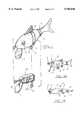
- FIG. 1is a front, perspective, "exploded” view of the complete fishing lure of the exemplary embodiments of the present invention, with the first embodiment (FIGS. 2A--2F) of the separately molded insert shown below the exterior body of the lure.
- FIGS. 1A & 1Bare side and top/plan views, respectively, of a complete fishing lure showing the over-all general arrangement of parts generally followed in the exemplary embodiments of the present invention, although it is noted that the detailed views of the remaining figures illustrate more accurately and in greater detail the exemplary dimensions and configurations of the bib and insert elements actually used in the exemplary embodiments of the present invention.
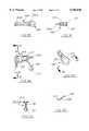
- FIG. 2Ais a side view of the combined bib, eyelet and insert members of a first exemplary embodiment of the bib/insert structure of the present invention which can used within the generalized lure of FIGS. 1A & 1B.
- FIG. 2Bis a bottom edge view of the insert embodiment of FIG. 2A.
- FIG. 2Cis side, close-up view of an exemplary, eyelet wire form used for the hook and line attachments for the generalized lure of FIGS. 1A & 1B and assembled within the bib/insert embodiment of FIG. 2A.
- FIG. 2Dis a rear view of the combined, initially and integrally molded, bib and insert elements of the embodiment of FIG. 2A, with the integrated, rear eyelet (in side, edge view) being visible; while
- FIG. 2Eis a cross-sectional view of the bib element or portion, taken along section lines A--A of FIG. 2D, at the maximum width area of the bib element.
- FIG. 2Fis a cross-sectional view of the insert element at its approximate mid-section, taken along section lines B--B of FIG. 2A, of the embodiment of FIG. 2A.
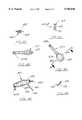
- FIG. 3Ais a side view of the combined bib, eyelet and insert members of a second, alternative, exemplary embodiment of the bib/insert structure of the present invention which can used within the generalized lure of FIGS. 1A & 1B.
- FIG. 3Bis a bottom edge view of the insert embodiment of FIG. 3A.
- FIG. 3Cis side, close-up view of an exemplary, eyelet wire form used for the hook and line attachments for the generalized lure of FIGS. 1A & 1B and assembled within the bib/insert embodiment of FIG. 3A.
- FIG. 3Dis a rear view of the combined, initially and integrally molded, bib and insert elements of the embodiment of FIG. 3A, with the integrated, rear eyelet (in side, edge view) being visible; while
- FIG. 3Eis a cross-sectional view of the bib element or portion, taken along section lines A--A of FIG. 3D, at the maximum width area of the bib element.
- FIG. 3Fis a cross-sectional view of the insert element at its approximate mid-section, taken along section lines B--B of FIG. 3A, of the embodiment of FIG. 3A.
- FIG. 4Ais a side view of the combined bib, eyelet and insert members of a third, alternative, exemplary embodiment of the bib/insert structure of the present invention which can used within the generalized lure of FIGS. 1A & 1B.
- FIG. 4Bis a bottom edge view of the insert embodiment of FIG. 4A.
- FIG. 4Cis side, close-up view of an exemplary, eyelet wire form used for the hook and line attachments for the generalized lure of FIGS. 1A & 1B and assembled within the bib/insert embodiment of FIG. 4A.
- FIG. 4Dis a rear view of the combined, initially and integrally molded, bib and insert elements of the embodiment of FIG. 4A, with the integrated, rear eyelet (in side, edge view) being visible; while
- FIG. 4Eis a cross-sectional view of the bib element or portion, taken along section lines A--A of FIG. 4D, at the maximum width area of the bib element.
- FIG. 4Fis a cross-sectional view of the insert element at its approximate mid-section, taken along section lines B--B of FIG. 4A, of the embodiment of FIG. 4A.
- FIG. 5is a flow chart, outlining the basic manufacturing methodology of the exemplary preferred embodiment of the present invention.
- the exemplary embodiment of the over-all fishing lure 1 of the present inventionincludes a molded plastic body 2 having a series of an exemplary, two sets of opposed slots 3 connected by relatively thin web portions 4.
- the slots 3 and web portions 4combine to form effectively "hinged” body sections, which move relatively to one another as the lure "swims," greatly adding to the life-like action of the lure 1.
- a pair of "eyes” 9are included on either side of the body 2 for enhanced visual simulation, while the body typically will be colored or ornamental adorned, as is well known in the fishing lure art.
- first eyelet 5to which the fisherman attaches the towing or pulling line (not illustrated), while a second eyelet 6 is included at the body's bottom for the attachment of a hook (not illustrated), all as well known in the prior art.
- a downwardly inclined, attached bib 7is included at the bottom, front end of the body 2.
- the eyelet structures 5 & 6 and the bib 7are integrally attached to insert member 8, the latter of which in essence forms the "skeleton" of the lure 1.
- FIGS. 1A & 1BExemplary dimensions for the body 2 and fish eye 9 are included in FIGS. 1A & 1B, which dimensions are incorporated herein by reference.!
- the first, exemplary insert member 200 of the present inventionincludes two eyelets 210 and a bib member 220.
- the insert member 200is generally flat, having preferably an over-all triangular shape or other appropriate shape with a squared-off base when viewed from its sides as seen in FIG. 2A, but with a strengthening rib 202 (note FIG. 2F) extending along and about its periphery.
- the insert member 200is generally extended in the longitudinal direction, with the first eyelet 210A at its front end "nose" or tip and the second eyelet 210B at its bottom toward its rear end.
- the bib member 220extends down at an exemplary angle of sixty-five (65°) degrees from the "horizontal.”
- the main body of the insert member 200includes a hole 203, through which the final over-molded plastic passes in the second, over-molding step, as explained more fully below.
- the eyelets 210A, 210Beach includes a distal, terminus ring 211, an extended base or stem 212 and proximal, terminus "feet” 213, all preferably integrally formed from a continuous wire form.
- a wireis bent about itself to form a circle or terminus ring 211 at its distal end to which a hook or line can be easily attached and held, going into two, side-by-side wire sections producing the extended base or stem 212, terminating in the proximal, terminus, preferably orthogonal "feet" 213.
- the bib member 220which is integrally formed with the insert 200, includes a forward, curved portion or "bib,” which interacts with the water flow to cause the lure 1 to travel at a desired depth, depending on, for example, what particular angle it makes with respect to the general line of travel, which typically would be along the center line of the lure body 2.
- the bib member 220is extended in its longitudinal dimension, with a somewhat flattened or oblong (i.e., non-circle), curved leading end tapering out to a small radii 224 along its peripheral edge (note FIG. 2E), producing a slanted side edge terminating in a peripheral line, in contrast to the flat bib with the flat, ninety (90°) degree or squared-off side edges of the prior art.
- the front side of the bibpreferably is flat, while the back side has the side edges tapering to a thin, preferably a line edge.
- the main, extended body 225 of the bib member 220has an exemplary, preferred thickness in its interior 225 of about eighty-five thousandths (0.085") of an inch at its thickest point, believed to be substantially less than that of the plastic bibs of the prior art.
- the wire forms for the eyelets 210A & 210Bare placed into pre-formed areas of the mold for the integrated insert member or portion 200 and the bib member or portion 220 to be molded together as an integrated whole.
- the wire form membersare initially assembled and integrated together into the insert and bib 200/220 in an initial molding step using insert molding preferably with a thermoplastic, which assemblage is then subsequently preferably molded into a soft plastic body in the desired form or fish configuration 2.
- FIGS. 2A-2FExemplary dimensions for the insert member 200, the eyelets 210 and the bib member 220 are included in FIGS. 2A-2F, which dimensions are incorporated herein by reference.!
- a second, alternative, exemplary insert member 300 of the present inventionalso includes two eyelets 310 and a bib member 320.
- the insert member 300is generally flat, having an exemplary, over-all triangular shape when viewed from its sides as seen in FIG. 3A, but with a strengthening rib 302 (note FIG. 3F) extended along and about its periphery.
- the insert member 300is generally extended in the longitudinal direction, with the first eyelet 310A at its front end "nose" or tip and the second eyelet 310B at its bottom toward its rear end.
- the bib member 320extends down at an exemplary angle of fifty-five (55°) degrees from the "horizontal.”
- the main body of the insert member 300includes holes 303, through which the final over-molded plastic passes in the second, over-molding step, as explained more fully below.
- the eyelets 310A, 310Beach includes a distal, terminus ring 311, an extended base 312 and proximal, terminus feet 313, all preferably integrally formed from a continuous wire form.
- a wireis bent about itself to form a circle or terminus ring 311 at its distal end to which a hook or line can be easily attached and held, going into two, side-by-side wire sections producing the extended base or stem 312, terminating in the proximal, terminus, preferably orthogonal "feet" 313.
- the bib member 320which is integrally formed with the insert 300, includes a forward, curved portion or "bib,” which interacts with the water flow to cause the lure 1 to travel at a desired depth, depending, for example, on what particular angle it makes with respect to the general line of travel, which typically would be along the center line of the lure body 2.
- the bib member 320is extended in its longitudinal dimension, with a somewhat flattened or oblong (i.e., non-circle), curved leading end tapering out to a small radii 324 along its peripheral edge (note FIG. 3E), producing a slanted side edge terminating in a peripheral line, in contrast to the flat bibs with the flat, ninety (90°) degree or squared-off side edges of the prior art.
- the front side of the bibpreferably is flat, while the back side has the side edges tapering to a thin, preferably a line edge.
- the main, extended body 325 of the bib member 320has an exemplary, preferred thickness in its interior 325 of about one-tenth (0.100") of an inch at its thickness point, believed to be substantially less than that of the plastic bibs of the prior art.
- the wire forms for the eyelets 310A & 310Bare placed into pre-formed areas of the mold for the integrated insert member or portion 300 and the bib member or portion 320 to be molded together as an integrated whole.
- the wire form membersare initially assembled and integrated together into the insert and bib 300/320 in an initial molding step using insert molding preferably with a thermoplastic, which assemblage is then subsequently preferably molded into a soft plastic body in the desired form or fish configuration 2.
- FIGS. 3A-3FExemplary dimensions for the insert member 300, the eyelets 310 and the bib member 320 are included in FIGS. 3A-3F, which dimensions are incorporated herein by reference.!
- the third, alternative, exemplary insert member 400 of the present inventionlikewise also includes two eyelets 410 and a bib member 420.
- the insert member 400is generally flat, having an exemplary, over-all, extended, angular shape with reversed symmetry about a "vertical" axis when viewed from its sides as seen in FIG. 4A, but with a strengthening rib 402 (note FIG. 4F) extending along its periphery.
- the insert member 400is generally extended in the longitudinal direction, with the first eyelet 410A at its front end "nose” or tip and the second eyelet 410B at its bottom toward its rear end.
- the bib member 420extends down at an exemplary angle of about Forty-nine (49°) degrees from the "horizontal.”
- the main body of the insert member 400includes holes 403, through which the final over-molded plastic passes in the second, over-molding step, as explained more fully below.
- the eyelets 410A, 410Beach includes a distal, terminus ring 411, an extended base 412 and proximal, terminus feet 413, all preferably integrally formed from a continuous wire form.
- a wireis bent about itself to form a circle or terminus ring 411 at its distal end to which a hook or line can be easily attached and held, going into two, side-by-side wire sections producing the extended base or stem 412, terminating in the proximal, terminus, preferably orthogonal "feet" 413.
- the bib member 420which is integrally formed with the insert 400, includes a forward, curved portion or "bib,” which interacts with the water flow to cause the lure 1 to travel at a desired depth, depending, for example, on what particular angle it makes with respect to the general line of travel, which typically would be along the center line of the lure body 2.
- the bib member 420is extended in its longitudinal dimension, with a somewhat flattened or oblong (i.e., non-circle), curved leading end tapering out to a small radii 424 along its peripheral edge (note FIG. 4E), which is integrally formed with the insert 400, in contrast to the flat bibs with the flat, ninety (90°) degree or squared-off side edges of the prior art.
- the front side of the bibpreferably is flat, while the back side has the side edges tapering to a thin, preferably a line edge.
- the main, extended body 425 of the bib member 420has an exemplary, preferred thickness in its interior 425 of about one-tenth (0.100") of an inch at its thickest point, believed to be substantially less than that of the plastic bibs of the prior art.
- the wire forms for the eyelets 410A & 410Bare placed into pre-formed areas of the mold for the integrated insert member or portion 400 and the bib member or portion 420 to be molded together as an integrated whole.
- the wire form membersare initially assembled and integrated together into the insert and bib 400/420 in an initial molding step using insert molding preferably with a thermoplastic, which assemblage is then subsequently preferably molded into a soft plastic body in the desired form or fish configuration 2.
- FIGS. 4A-4FExemplary dimensions for the insert member 400, the eyelets 410 and the bib member 420 are included in FIGS. 4A-4F, which dimensions are incorporated herein by reference.!
- Exemplary, over-all lengths for the finished luresare two, three and four (2", 3" & 4") inches, as represented by the exemplary, currently preferred embodiments of FIGS. 2A+, 3A+ & 4A+, respectively, although, of course, many other lengths could be used.
- the two, wire forms 210A, 210B(310A & B, 410A & B) for the two eyelets 5 & 6 are placed and appropriately positioned, placing the bases of the two wire forms, one wire form at a right angle to the other but with both located in the same plane as the other, in a first, smaller mold for the integrated insert 200 (300, 400) and bib 220 (320, 420).
- thermoplastice.g., clear polycarbonate
- insert 200300, 400
- bib 220320, 420
- the initial moldis configured to produce the desired bib shape, as described above, i.e., relatively narrow and oblong with a slanted side, peripheral, line edge, extending down at an exemplary angle within the range of about forty-nine to about sixty-five ( ⁇ 49-65°) degrees from the "horizontal,” i.e., from the center-line of the fish lure body.
- the clear, rigid, skeleton piece 8is then insert molded in a further, larger, second mold, which produces the properly configured, preferably soft lure body 2 having the desired characteristics of the marine animal or fish, including other type marine shapes, such as a worm, grub, frog, etc., that the lure 1 is intended to simulate, with the main portions of the bib 220 (320, 420) and the eyelet ends appropriately extending out side of the exterior body 2 of the lure 1.
- This second, over-molding processpreferably uses, for example, a plastisol compound using the liquid injection molding (LIM) process.
- LIMliquid injection molding
- TPEthermoplastic elastomer
- the second moldpreferably including the configurations to produce the slots 3 and the web members 4, producing a jointed lure with a life-like "swimming" action.
- the general plastic molding techniques of the first molding step and of the second, over-molding stepare well know to those of ordinary skill in the general art of plastic molding, and therefore, are not discussed in detail.
- the two step process of initially hard molding of the integrated wire forms 210A, 210B (310A & B, 410A & B), insert 200 (300, 400) and bib 220 (320, 420) surrounded and held together by the set plastic in a rigid, skeleton piece 8 and then over-molding it into the soft body plastic produced in the second molding step to produce the highly advantageous fishing lure 1 of the present inventionare, it is believed, unique and part of the present invention.
- the lurescan be made in different lengths, different body configurations, and with differently sized and configured bibs to meet the varying needs and applications of, for example, sports fishermen.
Landscapes
- Life Sciences & Earth Sciences (AREA)
- Environmental Sciences (AREA)
- Marine Sciences & Fisheries (AREA)
- Animal Husbandry (AREA)
- Biodiversity & Conservation Biology (AREA)
Abstract
Description
______________________________________ Patent No. Inventor Issue Date ______________________________________ 3,490,165 Thomassin 01/20/70 3,735,518 Klein et al 05/29/73 ______________________________________
Claims (9)
Priority Applications (2)
| Application Number | Priority Date | Filing Date | Title |
|---|---|---|---|
| US08/942,818US5946848A (en) | 1997-10-02 | 1997-10-02 | Fishing lure bib system |
| CA002219706ACA2219706A1 (en) | 1997-10-02 | 1997-10-28 | Fishing lure bib system |
Applications Claiming Priority (1)
| Application Number | Priority Date | Filing Date | Title |
|---|---|---|---|
| US08/942,818US5946848A (en) | 1997-10-02 | 1997-10-02 | Fishing lure bib system |
Publications (1)
| Publication Number | Publication Date |
|---|---|
| US5946848Atrue US5946848A (en) | 1999-09-07 |
Family
ID=25478644
Family Applications (1)
| Application Number | Title | Priority Date | Filing Date |
|---|---|---|---|
| US08/942,818Expired - Fee RelatedUS5946848A (en) | 1997-10-02 | 1997-10-02 | Fishing lure bib system |
Country Status (2)
| Country | Link |
|---|---|
| US (1) | US5946848A (en) |
| CA (1) | CA2219706A1 (en) |
Cited By (33)
| Publication number | Priority date | Publication date | Assignee | Title |
|---|---|---|---|---|
| US6393757B2 (en) | 1995-12-20 | 2002-05-28 | Christopher Atkins Bomann | Flesh-like jacket for fishing lures |
| US6532694B1 (en)* | 2002-01-02 | 2003-03-18 | Wayne Gathright | Method of casting lure and multi cavity mold therefor |
| US6560914B2 (en)* | 1999-04-19 | 2003-05-13 | C. Baxter Kruger | Fishing lure with life-like swimming action |
| US6796080B1 (en) | 2002-12-19 | 2004-09-28 | Richard S. Mathews, Jr. | Fishing lure |
| US6871442B2 (en)* | 2001-08-22 | 2005-03-29 | Daniel Wyatt | Expandable bait sleeve and method therefor |
| US6912808B1 (en)* | 2002-07-15 | 2005-07-05 | Luke Chi Kwong Mak | Fishing lure |
| US20050235550A1 (en)* | 2005-03-18 | 2005-10-27 | Mann's Bait Company | Fishing lures having elastomeric portions |
| US20060010764A1 (en)* | 2004-07-14 | 2006-01-19 | Frawley Brian P | Fishing lure having snap-on cover |
| US20060096152A1 (en)* | 2004-11-09 | 2006-05-11 | Pelegrin Steven J | Lighted fishing lure |
| US20060236588A1 (en)* | 2005-04-21 | 2006-10-26 | Donald Rapelje | Quick-disconnect soft bait fishing lure |
| US20070101636A1 (en)* | 2005-09-23 | 2007-05-10 | Monte Dolence | Two-piece, flow-through fishing lure |
| US20070261289A1 (en)* | 2006-03-01 | 2007-11-15 | Hobbins James B | Modular reinforced soft bait lure system |
| US20070289196A1 (en)* | 2006-06-20 | 2007-12-20 | Scott Jason E | Fish lure |
| US20090090041A1 (en)* | 2007-10-05 | 2009-04-09 | Derek Ross Brick | Fishing Lure |
| US20090307960A1 (en)* | 2008-06-17 | 2009-12-17 | Mann's Bait Company, Inc. | Hollow bait and method of making the same |
| US20090307959A1 (en)* | 2008-06-17 | 2009-12-17 | Bass Pro Intellectual Property, L.L.C. | Fishing lure |
| US20100115822A1 (en)* | 2008-11-13 | 2010-05-13 | Huddleston Deluxe Inc. | Weedless fishing lure device and related method |
| WO2010075513A1 (en)* | 2008-12-24 | 2010-07-01 | Wild River Consulting Group, Llc | Fishing lure having variable density materials |
| US20110072706A1 (en)* | 2009-02-13 | 2011-03-31 | Tsung-Hsi Tsai | Insect-Shaped Fake Bait Structure and a Shaping Method Thereof |
| US20110154715A1 (en)* | 2009-12-26 | 2011-06-30 | Tsung-Hsi Tsai | Compact fake bait structure |
| US20110239521A1 (en)* | 2010-03-30 | 2011-10-06 | Tsung-Hsi Tsai | Compact Fake Bait Structure |
| US8959827B1 (en)* | 2011-06-16 | 2015-02-24 | Robert E. Hale | Enhanced action fishing lures |
| US20150128478A1 (en)* | 2004-12-08 | 2015-05-14 | Huddleston Deluxe, Inc. | Fishing lure with vortex tail |
| US9474257B1 (en) | 2010-04-26 | 2016-10-25 | Robert McGilvry | Imitation crawdad artificial fishing lure |
| US20180000057A1 (en)* | 2016-06-30 | 2018-01-04 | Plastic Research And Development Corporation | Rattling paddle lure |
| US10051847B1 (en) | 2014-06-11 | 2018-08-21 | Bert E. Smith | Fishing lures and fishing lure production methods and uses |
| WO2019226928A1 (en)* | 2017-05-24 | 2019-11-28 | Adams Russell S | Improvements to bird deterring structure and method |
| US10701927B2 (en) | 2017-05-24 | 2020-07-07 | Russell S. Adams | Bird deterring structure and method |
| US11503817B1 (en) | 2018-09-19 | 2022-11-22 | Eric Smith | Fish lures and methods for making fish lures and luring fish |
| US11589565B1 (en)* | 2020-04-20 | 2023-02-28 | River2Sea, Llc | Clacking swimbait joint device |
| US11766037B2 (en) | 2017-05-24 | 2023-09-26 | Russell S. Adams | Broken wing bird effigy |
| USD1029176S1 (en) | 2021-03-11 | 2024-05-28 | Russell S. Adams | Bird deterring effigy (eagle) |
| USD1095746S1 (en)* | 2024-01-23 | 2025-09-30 | Chao Liu | Artificial bait |
Citations (31)
| Publication number | Priority date | Publication date | Assignee | Title |
|---|---|---|---|---|
| US1499819A (en)* | 1923-02-06 | 1924-07-01 | Bert G Goble | Artificial fish bait |
| CH206378A (en)* | 1939-02-28 | 1939-08-15 | Buetti Alberto | Artificial fish for fishing. |
| US2776518A (en)* | 1954-06-25 | 1957-01-08 | John T Felmlee | Fish lure |
| US2847791A (en)* | 1954-11-08 | 1958-08-19 | Clarence C Simmons | Fishing lure |
| US2938293A (en)* | 1956-04-17 | 1960-05-31 | Robert E Richardson | Fishing lure |
| US2971285A (en)* | 1959-03-31 | 1961-02-14 | Stephen A Murawski | Artificial casting bait |
| US3070917A (en)* | 1958-12-11 | 1963-01-01 | Sr David E Rowe | Fish lure |
| US3191336A (en)* | 1962-09-24 | 1965-06-29 | Jr Carl R Cordell | Fishing lure and method of making the same |
| US3218750A (en)* | 1964-06-08 | 1965-11-23 | Irving I Lewin | Fishing lure |
| US3367060A (en)* | 1965-05-10 | 1968-02-06 | Charles G. Abercrombie | Fish lure |
| US3490165A (en)* | 1966-10-24 | 1970-01-20 | Robert Charles Thomassin | Lure for fishing |
| US3514358A (en)* | 1968-06-03 | 1970-05-26 | Richard P Monaghan | Method of forming fishing lures and the like |
| US3611614A (en)* | 1969-09-24 | 1971-10-12 | Virgil V Ward | Fishing lure |
| FR2145083A5 (en)* | 1971-07-08 | 1973-02-16 | Thomassin Robert | Fishing lure - composed of flexible pvc sheet |
| US3735518A (en)* | 1971-03-19 | 1973-05-29 | R Kleine | Fishing lure having detachably positioned hooks |
| US3861073A (en)* | 1972-08-30 | 1975-01-21 | Robert Charles Thomassin | Flexible fishing lure |
| US4196884A (en)* | 1977-05-12 | 1980-04-08 | Zeman Jack R | Apparatus for making weedless elastomeric fishing lure |
| US4228611A (en)* | 1978-05-16 | 1980-10-21 | Loop-A-Line, Inc. | Method for fabricating fishing lures etc. |
| US4437257A (en)* | 1981-05-15 | 1984-03-20 | Kluge Douglas J | Foamed plastic fishing lure body having a controlled density and a one-piece wire and a method for its manufacture |
| US4654995A (en)* | 1985-09-04 | 1987-04-07 | Rapelje Donald G | Articulated fishing lure with reinforcement web |
| US4771567A (en)* | 1987-12-04 | 1988-09-20 | Cannon Rodney M | Fishing lure |
| US4864766A (en)* | 1988-05-05 | 1989-09-12 | Greg Bohn | Weedless jig |
| FR2652991A1 (en)* | 1989-10-18 | 1991-04-19 | Parenti Georges | Lure device for fishing |
| US5142811A (en)* | 1991-04-04 | 1992-09-01 | Freeman Carl W | Fishing lure and lure enhancement kit |
| US5193299A (en)* | 1991-04-09 | 1993-03-16 | Correll Robert P | Realistic swimming fish lure |
| DE4236848A1 (en)* | 1992-10-02 | 1994-04-07 | Wilhelm Leitner | Bait for fishing and method of making it |
| US5564220A (en)* | 1994-03-30 | 1996-10-15 | Blicha; Peter J. | Fishing lure and method for making the same |
| US5661921A (en)* | 1996-05-13 | 1997-09-02 | Mason; Marvin Howard | Artificial fishing lure with fins |
| US5678350A (en)* | 1994-10-27 | 1997-10-21 | Moore; Mark H. | Fish lure |
| US5725892A (en)* | 1996-03-26 | 1998-03-10 | Classic Fishing Products, Inc. | Apparatus for creating fishing worm having attractant discharge arrangement |
| US5815978A (en)* | 1996-12-16 | 1998-10-06 | Huddleston; Samuel M. | Soft bait fish lure |
- 1997
- 1997-10-02USUS08/942,818patent/US5946848A/ennot_activeExpired - Fee Related
- 1997-10-28CACA002219706Apatent/CA2219706A1/ennot_activeAbandoned
Patent Citations (31)
| Publication number | Priority date | Publication date | Assignee | Title |
|---|---|---|---|---|
| US1499819A (en)* | 1923-02-06 | 1924-07-01 | Bert G Goble | Artificial fish bait |
| CH206378A (en)* | 1939-02-28 | 1939-08-15 | Buetti Alberto | Artificial fish for fishing. |
| US2776518A (en)* | 1954-06-25 | 1957-01-08 | John T Felmlee | Fish lure |
| US2847791A (en)* | 1954-11-08 | 1958-08-19 | Clarence C Simmons | Fishing lure |
| US2938293A (en)* | 1956-04-17 | 1960-05-31 | Robert E Richardson | Fishing lure |
| US3070917A (en)* | 1958-12-11 | 1963-01-01 | Sr David E Rowe | Fish lure |
| US2971285A (en)* | 1959-03-31 | 1961-02-14 | Stephen A Murawski | Artificial casting bait |
| US3191336A (en)* | 1962-09-24 | 1965-06-29 | Jr Carl R Cordell | Fishing lure and method of making the same |
| US3218750A (en)* | 1964-06-08 | 1965-11-23 | Irving I Lewin | Fishing lure |
| US3367060A (en)* | 1965-05-10 | 1968-02-06 | Charles G. Abercrombie | Fish lure |
| US3490165A (en)* | 1966-10-24 | 1970-01-20 | Robert Charles Thomassin | Lure for fishing |
| US3514358A (en)* | 1968-06-03 | 1970-05-26 | Richard P Monaghan | Method of forming fishing lures and the like |
| US3611614A (en)* | 1969-09-24 | 1971-10-12 | Virgil V Ward | Fishing lure |
| US3735518A (en)* | 1971-03-19 | 1973-05-29 | R Kleine | Fishing lure having detachably positioned hooks |
| FR2145083A5 (en)* | 1971-07-08 | 1973-02-16 | Thomassin Robert | Fishing lure - composed of flexible pvc sheet |
| US3861073A (en)* | 1972-08-30 | 1975-01-21 | Robert Charles Thomassin | Flexible fishing lure |
| US4196884A (en)* | 1977-05-12 | 1980-04-08 | Zeman Jack R | Apparatus for making weedless elastomeric fishing lure |
| US4228611A (en)* | 1978-05-16 | 1980-10-21 | Loop-A-Line, Inc. | Method for fabricating fishing lures etc. |
| US4437257A (en)* | 1981-05-15 | 1984-03-20 | Kluge Douglas J | Foamed plastic fishing lure body having a controlled density and a one-piece wire and a method for its manufacture |
| US4654995A (en)* | 1985-09-04 | 1987-04-07 | Rapelje Donald G | Articulated fishing lure with reinforcement web |
| US4771567A (en)* | 1987-12-04 | 1988-09-20 | Cannon Rodney M | Fishing lure |
| US4864766A (en)* | 1988-05-05 | 1989-09-12 | Greg Bohn | Weedless jig |
| FR2652991A1 (en)* | 1989-10-18 | 1991-04-19 | Parenti Georges | Lure device for fishing |
| US5142811A (en)* | 1991-04-04 | 1992-09-01 | Freeman Carl W | Fishing lure and lure enhancement kit |
| US5193299A (en)* | 1991-04-09 | 1993-03-16 | Correll Robert P | Realistic swimming fish lure |
| DE4236848A1 (en)* | 1992-10-02 | 1994-04-07 | Wilhelm Leitner | Bait for fishing and method of making it |
| US5564220A (en)* | 1994-03-30 | 1996-10-15 | Blicha; Peter J. | Fishing lure and method for making the same |
| US5678350A (en)* | 1994-10-27 | 1997-10-21 | Moore; Mark H. | Fish lure |
| US5725892A (en)* | 1996-03-26 | 1998-03-10 | Classic Fishing Products, Inc. | Apparatus for creating fishing worm having attractant discharge arrangement |
| US5661921A (en)* | 1996-05-13 | 1997-09-02 | Mason; Marvin Howard | Artificial fishing lure with fins |
| US5815978A (en)* | 1996-12-16 | 1998-10-06 | Huddleston; Samuel M. | Soft bait fish lure |
Cited By (47)
| Publication number | Priority date | Publication date | Assignee | Title |
|---|---|---|---|---|
| US6393757B2 (en) | 1995-12-20 | 2002-05-28 | Christopher Atkins Bomann | Flesh-like jacket for fishing lures |
| US6560914B2 (en)* | 1999-04-19 | 2003-05-13 | C. Baxter Kruger | Fishing lure with life-like swimming action |
| US6871442B2 (en)* | 2001-08-22 | 2005-03-29 | Daniel Wyatt | Expandable bait sleeve and method therefor |
| US6532694B1 (en)* | 2002-01-02 | 2003-03-18 | Wayne Gathright | Method of casting lure and multi cavity mold therefor |
| US6912808B1 (en)* | 2002-07-15 | 2005-07-05 | Luke Chi Kwong Mak | Fishing lure |
| US6796080B1 (en) | 2002-12-19 | 2004-09-28 | Richard S. Mathews, Jr. | Fishing lure |
| US20060010764A1 (en)* | 2004-07-14 | 2006-01-19 | Frawley Brian P | Fishing lure having snap-on cover |
| US20060096152A1 (en)* | 2004-11-09 | 2006-05-11 | Pelegrin Steven J | Lighted fishing lure |
| US7107717B2 (en)* | 2004-11-09 | 2006-09-19 | Steven J Pelegrin | Lighted fishing lure |
| US20150128478A1 (en)* | 2004-12-08 | 2015-05-14 | Huddleston Deluxe, Inc. | Fishing lure with vortex tail |
| US20060037230A2 (en)* | 2005-03-18 | 2006-02-23 | Mann's Bait Company | Fishing lures having elastomeric portions |
| US7266922B2 (en)* | 2005-03-18 | 2007-09-11 | Mann's Bait Company | Fishing lures having elastomeric portions |
| US20050235550A1 (en)* | 2005-03-18 | 2005-10-27 | Mann's Bait Company | Fishing lures having elastomeric portions |
| US9345237B2 (en) | 2005-04-21 | 2016-05-24 | Donald Rapelje | Quick-disconnect soft bait fishing lure |
| US20060236588A1 (en)* | 2005-04-21 | 2006-10-26 | Donald Rapelje | Quick-disconnect soft bait fishing lure |
| US20070101636A1 (en)* | 2005-09-23 | 2007-05-10 | Monte Dolence | Two-piece, flow-through fishing lure |
| WO2007103691A3 (en)* | 2006-03-01 | 2008-09-18 | James Benjamin Hobbins | Modular reinforced soft bait lure system |
| US20070261289A1 (en)* | 2006-03-01 | 2007-11-15 | Hobbins James B | Modular reinforced soft bait lure system |
| US20070289196A1 (en)* | 2006-06-20 | 2007-12-20 | Scott Jason E | Fish lure |
| US7356963B2 (en)* | 2006-06-20 | 2008-04-15 | Scott Jason E | Fish lure |
| US20090090041A1 (en)* | 2007-10-05 | 2009-04-09 | Derek Ross Brick | Fishing Lure |
| US7637050B2 (en)* | 2007-10-05 | 2009-12-29 | Slog, LLC | Fishing lure |
| US8789308B2 (en)* | 2008-06-17 | 2014-07-29 | Bass Pro Intellectual Property, L.L.C. | Fishing lure |
| US20090307960A1 (en)* | 2008-06-17 | 2009-12-17 | Mann's Bait Company, Inc. | Hollow bait and method of making the same |
| US20090307959A1 (en)* | 2008-06-17 | 2009-12-17 | Bass Pro Intellectual Property, L.L.C. | Fishing lure |
| US20100287812A2 (en)* | 2008-06-17 | 2010-11-18 | Bass Pro Intellectual Property, L.L.C. | Fishing lure |
| US8857100B2 (en)* | 2008-11-13 | 2014-10-14 | Huddleston Deluxe, Inc. | Weedless fishing lure device and related method |
| US20100115822A1 (en)* | 2008-11-13 | 2010-05-13 | Huddleston Deluxe Inc. | Weedless fishing lure device and related method |
| US20100175305A1 (en)* | 2008-12-24 | 2010-07-15 | Heikkila Kurt E | Fishing Lure Having Variable Density Materials |
| WO2010075513A1 (en)* | 2008-12-24 | 2010-07-01 | Wild River Consulting Group, Llc | Fishing lure having variable density materials |
| US20110072706A1 (en)* | 2009-02-13 | 2011-03-31 | Tsung-Hsi Tsai | Insect-Shaped Fake Bait Structure and a Shaping Method Thereof |
| US20110154715A1 (en)* | 2009-12-26 | 2011-06-30 | Tsung-Hsi Tsai | Compact fake bait structure |
| US20110239521A1 (en)* | 2010-03-30 | 2011-10-06 | Tsung-Hsi Tsai | Compact Fake Bait Structure |
| US9474257B1 (en) | 2010-04-26 | 2016-10-25 | Robert McGilvry | Imitation crawdad artificial fishing lure |
| US8959827B1 (en)* | 2011-06-16 | 2015-02-24 | Robert E. Hale | Enhanced action fishing lures |
| US10588300B2 (en) | 2014-06-11 | 2020-03-17 | Bert E. Smith | Fishing lures and fishing lure production methods and uses |
| US10051847B1 (en) | 2014-06-11 | 2018-08-21 | Bert E. Smith | Fishing lures and fishing lure production methods and uses |
| US20180000057A1 (en)* | 2016-06-30 | 2018-01-04 | Plastic Research And Development Corporation | Rattling paddle lure |
| WO2019226928A1 (en)* | 2017-05-24 | 2019-11-28 | Adams Russell S | Improvements to bird deterring structure and method |
| US10701927B2 (en) | 2017-05-24 | 2020-07-07 | Russell S. Adams | Bird deterring structure and method |
| US11350623B2 (en) | 2017-05-24 | 2022-06-07 | Russell S. Adams | Bird deterring structure and method |
| US11766037B2 (en) | 2017-05-24 | 2023-09-26 | Russell S. Adams | Broken wing bird effigy |
| US12329145B2 (en) | 2017-05-24 | 2025-06-17 | Russell S. Adams | Broken wing bird effigy |
| US11503817B1 (en) | 2018-09-19 | 2022-11-22 | Eric Smith | Fish lures and methods for making fish lures and luring fish |
| US11589565B1 (en)* | 2020-04-20 | 2023-02-28 | River2Sea, Llc | Clacking swimbait joint device |
| USD1029176S1 (en) | 2021-03-11 | 2024-05-28 | Russell S. Adams | Bird deterring effigy (eagle) |
| USD1095746S1 (en)* | 2024-01-23 | 2025-09-30 | Chao Liu | Artificial bait |
Also Published As
| Publication number | Publication date |
|---|---|
| CA2219706A1 (en) | 1999-04-02 |
Similar Documents
| Publication | Publication Date | Title |
|---|---|---|
| US5946848A (en) | Fishing lure bib system | |
| US5678350A (en) | Fish lure | |
| US3497987A (en) | Artificial fishing lure | |
| US8640378B2 (en) | Elastomeric cover for the weighted head of a jig-type fishing lure | |
| US4783928A (en) | Fishing lure | |
| US5094026A (en) | Trolling squid lure | |
| US5193299A (en) | Realistic swimming fish lure | |
| US6912808B1 (en) | Fishing lure | |
| US4317305A (en) | Artificial lure | |
| US5806234A (en) | Fishing lure jig head and body | |
| US4045903A (en) | Artificial fishing lure | |
| US5381620A (en) | Lure utilizing easily changed aft portion of soft, flexible texture | |
| US4887377A (en) | Shad type fish bait with nose cavity | |
| US7497046B1 (en) | Slow sink lure | |
| US4596086A (en) | Weed guard and fishing jig incorporating same | |
| US4196884A (en) | Apparatus for making weedless elastomeric fishing lure | |
| US20060260176A1 (en) | Apparatus and method for a reinforced segmented fishing lure | |
| US20230107358A1 (en) | Modular fishing-lure system and methods of manufacture | |
| US7845107B1 (en) | Artificial interchangeable hybrid lure with perforations | |
| US5131181A (en) | One legged frog fish lure | |
| US2792662A (en) | Fishing lure | |
| JP4005928B2 (en) | Bendable lure | |
| US4141170A (en) | Artificial fishing lures and process for molding same | |
| US3680249A (en) | Artificial fishing lure | |
| US2611205A (en) | Fishing lure |
Legal Events
| Date | Code | Title | Description |
|---|---|---|---|
| AS | Assignment | Owner name:POSSUM LURES, INC., PENNSYLVANIA Free format text:ASSIGNMENT OF ASSIGNORS INTEREST;ASSIGNORS:YSTEBOE, HOWARD T.;SIPPLE, CHERYL;REEL/FRAME:008781/0795 Effective date:19970926 | |
| FEPP | Fee payment procedure | Free format text:PETITION RELATED TO MAINTENANCE FEES GRANTED (ORIGINAL EVENT CODE: PMFG); ENTITY STATUS OF PATENT OWNER: SMALL ENTITY Free format text:PETITION RELATED TO MAINTENANCE FEES FILED (ORIGINAL EVENT CODE: PMFP); ENTITY STATUS OF PATENT OWNER: SMALL ENTITY | |
| REMI | Maintenance fee reminder mailed | ||
| REIN | Reinstatement after maintenance fee payment confirmed | ||
| FP | Lapsed due to failure to pay maintenance fee | Effective date:20030907 | |
| FPAY | Fee payment | Year of fee payment:4 | |
| SULP | Surcharge for late payment | ||
| PRDP | Patent reinstated due to the acceptance of a late maintenance fee | Effective date:20031118 | |
| FEPP | Fee payment procedure | Free format text:PAYOR NUMBER ASSIGNED (ORIGINAL EVENT CODE: ASPN); ENTITY STATUS OF PATENT OWNER: SMALL ENTITY | |
| AS | Assignment | Owner name:CORRIE, ALEXANDER S.G., AUSTRALIA Free format text:COURT ORDER AND BILL OF SALE;ASSIGNOR:POSSUM LURES, INC.;REEL/FRAME:018552/0067 Effective date:20030530 | |
| FPAY | Fee payment | Year of fee payment:8 | |
| REMI | Maintenance fee reminder mailed | ||
| LAPS | Lapse for failure to pay maintenance fees | ||
| STCH | Information on status: patent discontinuation | Free format text:PATENT EXPIRED DUE TO NONPAYMENT OF MAINTENANCE FEES UNDER 37 CFR 1.362 | |
| FP | Lapsed due to failure to pay maintenance fee | Effective date:20110907 |