US5945948A - Method and apparatus for location finding in a communication system - Google Patents
Method and apparatus for location finding in a communication systemDownload PDFInfo
- Publication number
- US5945948A US5945948AUS08/706,751US70675196AUS5945948AUS 5945948 AUS5945948 AUS 5945948AUS 70675196 AUS70675196 AUS 70675196AUS 5945948 AUS5945948 AUS 5945948A
- Authority
- US
- United States
- Prior art keywords
- location
- signal
- base station
- subscriber unit
- determining
- Prior art date
- Legal status (The legal status is an assumption and is not a legal conclusion. Google has not performed a legal analysis and makes no representation as to the accuracy of the status listed.)
- Expired - Lifetime
Links
- 238000000034methodMethods0.000titleclaimsabstractdescription102
- 238000004891communicationMethods0.000titleclaimsabstractdescription36
- 230000007480spreadingEffects0.000claimsabstractdescription18
- 238000005259measurementMethods0.000claimsdescription50
- 230000004044responseEffects0.000claimsdescription16
- 230000001413cellular effectEffects0.000claimsdescription13
- 230000003247decreasing effectEffects0.000claims1
- 238000013507mappingMethods0.000claims1
- 230000008569processEffects0.000description16
- 238000010586diagramMethods0.000description14
- 238000012360testing methodMethods0.000description13
- 230000001934delayEffects0.000description9
- 230000006870functionEffects0.000description9
- 230000005540biological transmissionEffects0.000description7
- 238000001514detection methodMethods0.000description7
- 238000012545processingMethods0.000description7
- 230000003044adaptive effectEffects0.000description6
- 238000013459approachMethods0.000description6
- 238000004364calculation methodMethods0.000description6
- 230000006872improvementEffects0.000description6
- 230000000737periodic effectEffects0.000description6
- 238000012935AveragingMethods0.000description5
- 230000000875corresponding effectEffects0.000description4
- 238000011084recoveryMethods0.000description4
- 230000004075alterationEffects0.000description3
- 230000008901benefitEffects0.000description3
- 230000008094contradictory effectEffects0.000description3
- 230000000694effectsEffects0.000description3
- 239000011159matrix materialSubstances0.000description3
- 239000000523sampleSubstances0.000description3
- 239000013598vectorSubstances0.000description3
- 230000004913activationEffects0.000description2
- 238000003491arrayMethods0.000description2
- 230000008859changeEffects0.000description2
- 238000012937correctionMethods0.000description2
- 230000003111delayed effectEffects0.000description2
- 230000000977initiatory effectEffects0.000description2
- 230000004048modificationEffects0.000description2
- 238000012986modificationMethods0.000description2
- 230000001133accelerationEffects0.000description1
- 238000004458analytical methodMethods0.000description1
- 239000000969carrierSubstances0.000description1
- 238000007796conventional methodMethods0.000description1
- 230000002596correlated effectEffects0.000description1
- 238000013461designMethods0.000description1
- 238000005516engineering processMethods0.000description1
- 238000001914filtrationMethods0.000description1
- 238000011835investigationMethods0.000description1
- 230000005855radiationEffects0.000description1
- 238000005070samplingMethods0.000description1
- 238000000926separation methodMethods0.000description1
- 230000011664signalingEffects0.000description1
- 238000001228spectrumMethods0.000description1
- 230000001360synchronised effectEffects0.000description1
- 230000026676system processEffects0.000description1
- 238000012876topographyMethods0.000description1
- 230000007704transitionEffects0.000description1
- 238000012795verificationMethods0.000description1
Images


Classifications
- G—PHYSICS
- G01—MEASURING; TESTING
- G01S—RADIO DIRECTION-FINDING; RADIO NAVIGATION; DETERMINING DISTANCE OR VELOCITY BY USE OF RADIO WAVES; LOCATING OR PRESENCE-DETECTING BY USE OF THE REFLECTION OR RERADIATION OF RADIO WAVES; ANALOGOUS ARRANGEMENTS USING OTHER WAVES
- G01S3/00—Direction-finders for determining the direction from which infrasonic, sonic, ultrasonic, or electromagnetic waves, or particle emission, not having a directional significance, are being received
- G01S3/02—Direction-finders for determining the direction from which infrasonic, sonic, ultrasonic, or electromagnetic waves, or particle emission, not having a directional significance, are being received using radio waves
- H—ELECTRICITY
- H04—ELECTRIC COMMUNICATION TECHNIQUE
- H04W—WIRELESS COMMUNICATION NETWORKS
- H04W64/00—Locating users or terminals or network equipment for network management purposes, e.g. mobility management
- G—PHYSICS
- G01—MEASURING; TESTING
- G01S—RADIO DIRECTION-FINDING; RADIO NAVIGATION; DETERMINING DISTANCE OR VELOCITY BY USE OF RADIO WAVES; LOCATING OR PRESENCE-DETECTING BY USE OF THE REFLECTION OR RERADIATION OF RADIO WAVES; ANALOGOUS ARRANGEMENTS USING OTHER WAVES
- G01S5/00—Position-fixing by co-ordinating two or more direction or position line determinations; Position-fixing by co-ordinating two or more distance determinations
- G01S5/02—Position-fixing by co-ordinating two or more direction or position line determinations; Position-fixing by co-ordinating two or more distance determinations using radio waves
- G01S5/0205—Details
- G01S5/021—Calibration, monitoring or correction
- G—PHYSICS
- G01—MEASURING; TESTING
- G01S—RADIO DIRECTION-FINDING; RADIO NAVIGATION; DETERMINING DISTANCE OR VELOCITY BY USE OF RADIO WAVES; LOCATING OR PRESENCE-DETECTING BY USE OF THE REFLECTION OR RERADIATION OF RADIO WAVES; ANALOGOUS ARRANGEMENTS USING OTHER WAVES
- G01S5/00—Position-fixing by co-ordinating two or more direction or position line determinations; Position-fixing by co-ordinating two or more distance determinations
- G01S5/02—Position-fixing by co-ordinating two or more direction or position line determinations; Position-fixing by co-ordinating two or more distance determinations using radio waves
- G01S5/04—Position of source determined by a plurality of spaced direction-finders
- G—PHYSICS
- G01—MEASURING; TESTING
- G01S—RADIO DIRECTION-FINDING; RADIO NAVIGATION; DETERMINING DISTANCE OR VELOCITY BY USE OF RADIO WAVES; LOCATING OR PRESENCE-DETECTING BY USE OF THE REFLECTION OR RERADIATION OF RADIO WAVES; ANALOGOUS ARRANGEMENTS USING OTHER WAVES
- G01S5/00—Position-fixing by co-ordinating two or more direction or position line determinations; Position-fixing by co-ordinating two or more distance determinations
- G01S5/02—Position-fixing by co-ordinating two or more direction or position line determinations; Position-fixing by co-ordinating two or more distance determinations using radio waves
- G01S5/12—Position-fixing by co-ordinating two or more direction or position line determinations; Position-fixing by co-ordinating two or more distance determinations using radio waves by co-ordinating position lines of different shape, e.g. hyperbolic, circular, elliptical or radial
- G—PHYSICS
- G01—MEASURING; TESTING
- G01S—RADIO DIRECTION-FINDING; RADIO NAVIGATION; DETERMINING DISTANCE OR VELOCITY BY USE OF RADIO WAVES; LOCATING OR PRESENCE-DETECTING BY USE OF THE REFLECTION OR RERADIATION OF RADIO WAVES; ANALOGOUS ARRANGEMENTS USING OTHER WAVES
- G01S5/00—Position-fixing by co-ordinating two or more direction or position line determinations; Position-fixing by co-ordinating two or more distance determinations
- G01S5/02—Position-fixing by co-ordinating two or more direction or position line determinations; Position-fixing by co-ordinating two or more distance determinations using radio waves
- G01S5/0205—Details
- G01S5/0215—Interference
- G—PHYSICS
- G01—MEASURING; TESTING
- G01S—RADIO DIRECTION-FINDING; RADIO NAVIGATION; DETERMINING DISTANCE OR VELOCITY BY USE OF RADIO WAVES; LOCATING OR PRESENCE-DETECTING BY USE OF THE REFLECTION OR RERADIATION OF RADIO WAVES; ANALOGOUS ARRANGEMENTS USING OTHER WAVES
- G01S5/00—Position-fixing by co-ordinating two or more direction or position line determinations; Position-fixing by co-ordinating two or more distance determinations
- G01S5/02—Position-fixing by co-ordinating two or more direction or position line determinations; Position-fixing by co-ordinating two or more distance determinations using radio waves
- G01S5/0294—Trajectory determination or predictive filtering, e.g. target tracking or Kalman filtering
Definitions
- the present inventionrelates, in general, to wireless communication systems and, more particularly, to a method and apparatus for locating a subscriber unit in a Code Division Multiple Access (CDMA) wireless communication system.
- CDMACode Division Multiple Access
- AMPSAdvanced Mobile Phone System
- a usercould be located within a cell by determining which base station antenna was used to serve the user.
- a cellcould be as large as 3-5 miles in radius, making this information practically useless.
- many of the dense urban cell sitesare now much smaller, and many of the urban/suburban cell sites are now sectored, using sectored antennas to limit a channel's service area to just one sector of a cell, the coverage areas of a cell are now smaller. However, the area even in these smaller cells can still be more than one square mile. This still makes locating a user impractical for most purposes.
- Other radio systemslike US Digital Cellular (USDC) and Group Speciale Mobile (GSM) use the same method of identifying the cell or sector, and thus could do no better than the AMPS system.
- USDCDigital Cellular
- GSMGroup Speciale Mobile
- GPSGlobal Positioning System
- a method for determining a subscriber unit location in a communication systemincludes the steps of receiving a signal from the subscriber unit at a first base station, determining a first receive time of the signal based on a sequence of spreading symbols at the first base station, determining a first angle of arrival of the signal at the first base station, and determining the location of the subscriber unit from the first receive time, the first angle of arrival, and further predetermined information about the first and second base stations.
- the signalis formed via modulation by the sequence of spreading symbols.
- a method for estimating a subscriber unit locationincludes the steps of performing a first location measurement having a first confidence level, performing a second location measurement having a second confidence level, and determining an estimated location of the subscriber unit based on the first and second location measurements.
- the first location measurementis determined by receiving a signal from the subscriber unit at a first base station, determining a first receive time of the signal based on the sequence of spreading symbols at the first base station, and determining a first angle of arrival of the signal at the first base station.
- the signalis formed via modulation by the sequence of spreading symbols.
- a communication systemincludes a controller and a location processor that is responsive to the controller.
- the controlleris responsive to a first and a second base station, each of the first and second base stations comprising a receiver operable for receiving a signal from the communication unit, the signal being formed via modulation by a sequence of spreading symbols, and a detector operable for determining a receive time of the signal based on the sequence.
- the location processoris responsive to the controller and is operable for requesting the first and second base stations to determine first and second receive times of the signal based on the sequence, and for determining a location of the communication unit from the first and second receive times and further information about the first and second base stations.
- a method for determining location of a subscriber unitincludes receiving a first signal from a first base station of the plural base stations and a second signal from a second base station of the plural base stations, determining a first receive time based on a first sequence and a second receive time based on a second sequence, and determining the location of the subscriber unit from the first and second receive times and further information about the first and second base stations.
- the first and second signalsare formed based on the first sequence of symbols and the second sequence of symbols, respectively.
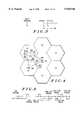
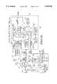
- FIG. 1is a simplified diagram illustrating a cellular system which may employ the present invention
- FIG. 2is a block diagram of a CDMA receiver at a subscriber unit according to a first embodiment of the invention
- FIG. 3is a diagram illustrating location finding of a CDMA subscriber unit according to an embodiment of the invention.
- FIG. 4is a diagram illustrating a timing sequence used in determining propagation delay for location of a CDMA subscriber unit according to an embodiment of the invention
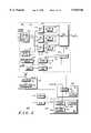
- FIG. 5is a block diagram of a CDMA receiver at a base station according to an embodiment of the invention.
- FIG. 6is a timeline diagram illustrating propagation and delay times used in calculating a subscriber according to an embodiment of the invention
- FIG. 7is a flow chart illustrating the process by which a subscriber measures base station signals according to an embodiment of the invention.
- FIG. 8is a flow chart illustrating the process by which a base station measures subscriber signals according to an embodiment of the invention
- FIG. 9-13are diagrams illustrating location finding of a subscriber unit in accordance with a second embodiment.
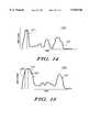
- FIG. 14-15are general diagrams illustrating reception of a signal from a subscriber unit by a base station
- FIG. 16is a diagram illustrating location finding of a subscriber unit when there is an obstruction between the subscriber unit and a base station.
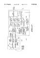
- FIG. 17is a block diagram of a first receiver implementation in a base station for use in location finding according to the second embodiment
- FIG. 18is a block diagram of a second receiver implementation in a base station for use in location finding according to the second embodiment.
- FIG. 19is a block diagram of a third receiver implementation in a base station for use in location finding according to the second embodiment.
- a first embodiment of the inventionis a system for determining the location of a user in a Code Division Multiple Access (CDMA) cellular system.
- CDMACode Division Multiple Access
- an estimate of the time of flight or propagationis made of the first arriving ray at a subscriber unit.
- the first ray receivedtypically represents the shortest path between the base and subscriber, and the time of flight estimate allows the calculation of the distance between the subscriber and the base station.
- a specific subscriber locationcan be calculated limited by the accuracy's of the measurement timing and other processing delays.
- the time of flight of the signal between each base and subscriberis calculated automatically within a correlation receiver.
- the processing stepsinvolve the transmission of a Pseudo Noise (PN) sequence coded signal time-aligned to under a chip accuracy (e.g., 1/16th of a chip), and correlating on this signal at the receiver using a correlation algorithm.
- PNPseudo Noise
- the modulation sequencee.g., a PN sequence
- a precise time of reception of a given chipcan be determined.
- a time delaycan be calculated and used to determine a position estimate.
- the subscriberuses known PN sequence and offset information to determine which related PN chips from different bases (standard and/or auxiliary bases) that were transmitted at the same time, and also determines the time of reception of these related chips. From the difference between the reception times, a time differential and thus distance differential is determined. Using the distance differentials and known positions of the bases, a position estimate is determined. Where a subscriber is only in communication with one or two bases, additional bases may be forced into an active set (including auxiliary sites, if needed) so that time measurements can be made by the subscriber.
- receiving base sitesare controlled to make time measurements of selected chips, and the difference in receive time is used to similarly calculate the subscriber position.
- auxiliary sitesare controlled so as to receive the signals transmitted from the subscriber unit. If necessary, in case of an emergency, the subscriber unit is powered up to a maximum power level such that at least three base stations can receive and make a time estimate of the signal. Further, where more precise measurements are needed, a special location message can be transmitted to the subscriber. Upon receipt, the subscriber determines a chip/time offset for a response signal, encodes the offset and transmits the response signal.
- a delay compensated time valueis determined for the various propagation paths, and the position determined therefrom.
- a cellular systemis generally depicted as 100 having a hexagonal cell pattern with base stations 110, 120, 130, and a subscriber 140.
- Auxiliary base units 121are also located between bases 110, 120 and 130.
- the distance between bases 110, 121 and 130 and the subscriber unit 140is estimated by determining the time of flight or propagation of the first arriving ray which is measured from a predefined reference time to the point in time that the receiver performs a correlation on the transmitted signal.
- the distance estimatemay be overestimated, or underestimated since the measurement is made to an arbitrary time reference point in the receiver (a precise measurement would only be available if a more accurate (and costly) timing system such as one derived from a GPS signal or atomic clock is used in the subscriber 140).
- the distances 150, 160 and 170may be longer or shorter than the actual distance between each base 110, 121, 130 and the subscriber 140 based on correlation to a chip rate (at an approximately 814 nanosecond (ns) chip rate (i.e., the rate of the fully spread signal, which is determined in TIA (Telecommunications Industry Association) Interim Standard IS-95A by the PN sequence rate), or approximately 250 meters (m) per chip; so it is desirable to achieve time measurements at faster than the chip rate).
- nsnanosecond
- the distance 150is shown to be overestimated indicating a point 125 beyond the subscriber unit's actual location.
- points 115 and 135are also overestimated. These points will be corrected by the distance processing described below, yielding an estimate much closer to the subscriber's true location.
- FIG. 2is a block diagram illustrating a CDMA subscriber unit 200 having a CDMA receiver 201, locator unit 202, and transmitter 203.
- the receiver 201has a common RF (radio frequency) front end 205 which feeds three independent rake inputs, 210, 220, 230.
- These rake units 210, 220 and 230can lock onto three different received rays that are approximately one PN chip time or more apart, which is typical of a direct sequence spread spectrum (DSSS) receiver.
- the searcher 240scans for new correlation peaks at faster than the chip rate (in the preferred case allowing for resolutions as fast as the 50 ns clock rate), and can reassign the rake inputs based on its best estimate of current channel conditions.
- the correlators for rakes 210, 220 and 230lock onto the three strongest rays that are available, and when a second or third base station can supply a signal sufficiently strong, they are reserved for locking onto these other base stations signals which are also delayed in time more than one PN chip time respectively, as described by the IS-95A Standard. If only two base stations are sufficiently strong, then two rays are dedicated, one for each base station, and the third ray to the strongest remaining ray for either base station.
- a location finding functionWhen a location finding function is desired by the subscriber 200, it is preferable to attempt to find three different base stations, one for each ray so that sufficient information is available to accurately estimate the location.
- the rakes 210, 220 and 230are adjusted so that at least three base unit signals are decoded.
- emergency pilot generatorssuch as auxiliary base unit 121 of FIG. 1 physically located between the base sites could be activated in response to a beacon request in order to blanket the area with additional reference signals, allowing the subscriber to make location estimates based on these pilot generators as well as the standard base sites.
- These auxiliary unitswould have a different PN offset than the surrounding base stations, and would typically be equipped with a GPS receiver for proper synchronization/timing.
- auxiliary unitscould be equipped with scanning receivers that, in response to a request signal by a subscriber, would begin transmitting for a limited period (e.g., 5 seconds, in order to minimize system interference).
- auxiliary unitscan be used to reduce uncertainties at certain locations or generally increase the accuracy of position finding in strategic areas, such as major highways, malls, or central business districts. Because of the interference-limiting nature of a CDMA system, in some cases only one base station will be able to receive the subscriber's signal, and vice-versa, so the auxiliary units are needed to obtain the necessary multiple readings.
- the relative time of reception of each signalis determined by using information about the leading edge (or alternately, the peaks) of related correlation peaks in the searcher, and adjusting this by an offset determined in a fine time alignment circuit (e.g., delay lock loops (DLLs) 215, 225 or 235 for each branch, coupled with filters 250-270).
- a fine time alignment circuite.g., delay lock loops (DLLs) 215, 225 or 235 for each branch, coupled with filters 250-270.
- DLLsdelay lock loops
- related correlation peaksare those received on different branches but within one chip of each other.
- the precise time of the leading edgeis determined, along with the PN sequence number (i.e., the chip position (e.g., number 245) of the repeating PN sequence (e.g., approximately 16,000 chips in length)).
- DLLs 215, 225, and 235are fed back to each rake 210, 220 and 230, respectively, for adjusting the signals to output fine time aligned signals.
- the DLL outputscan also serve as fine phase offset information for adjusting the receive times of the PN chips, preferably after filtering in Low Pass Filters (LPFs) 250, 260, 270 for each channel, respectively, which effectively averages the outputs of each DLL 215, 225, 235.
- LPFsLow Pass Filters
- Location searcher 280takes the fine phase offset information from each branch and corrects the time of reception from searcher 240 for each chip, to give a corrected relative time of reception for each branch. From the earliest time, say B1 (i.e., the time the signal from base 1 is received), the difference tB21 and tB31 in reception time for the other signals B2 and B3 is determined, and the corresponding distances dB21 and dB31 determined. One thus knows that the distance from bases 1 (110), 2 (120) and 3 (130) are dB1, (dB1+dB21) and (dB1+dB31), respectively. Further, from the PN offsets, the identity of the bases are known and their geographic position can be retrieved from memory 281.
- the known base locationsare used to define three lines L12 (151), L23 (152) and L13 (153).
- the distances dB21 and dB31are subtracted from lines L12 (151), L23 (152) and L23 (152), L13 (153) respectively, and the remaining segments bisected by normal lines N12 (154), N23 (156) and N13 (155).
- the intersection of these lines N12 (154), N23 (156) and N13 (155)is the position of the subscriber 140.
- This informationcould then be sent to the serving base station for forwarding to a requesting party of serving location register, or could be forwarded for use by the subscriber (e.g., on a map grid or other location device, not shown).
- the phase offset, chip, timing and base offset informationcan be sent in a location request signal to a serving base station.
- a location searchercan access its own database and determine the subscriber location. This location information is then transmitted back in a location response message to the subscriber or other requesting entity.
- FIG. 5generally depicts a block diagram of a CDMA infrastructure system 300 having a first CDMA base station 301.
- Base 301has a common RF front end 305 which feeds four independent rake inputs, shown as 310, 320, . . . 330.
- These rakescan lock onto four different received rays that are at least one PN chip time apart, which is typical of a DSSS receiver.
- the two searchers 340scan for new correlation peaks, and can reassign the rakes based on its best estimate of current channel conditions. Normally, the four correlators of rakes 310, 320, 330 lock onto the four strongest rays that are available.
- a location finding functionWhen a location finding function is desired, two general approaches are available--either passive (i.e., no subscriber unit response) or active. In either case it is preferable to find at least three different base stations capable of receiving a subscriber signal, so that sufficient information is available to estimate the location.
- passive modefour rake branches 310, 320 . . . 330 of base 301 are used to detect an uplink signal. From each rake, a Delay Lock Loop (DLL) is used to generate an estimate of the timing (i.e., adjustment) of the correlated ray. This more accurately estimates the time of the correlation, similar to the process used by the subscriber unit above.
- DLLDelay Lock Loop
- Searcher and Chip/Time Detector 340 peakcorrelates the signal on each branch, and also determines the best branch to use (preferably based on the earliest received peak for the same chip, but other selection techniques may be used to determine a current best branch); this best branch signal is used in determining PN chip and receive time information, similar to that in subscriber searcher 240.
- a commandis initiated within the system 300, most likely at a regional entity such as a mobile switching center (MSC) 365, operations center, or perhaps within a connected network such as PSTN (public switched telephone network) 375.
- a location requestis then processed via home location register (HLR) 366 to determine the currently serving base station(s).
- HLRhome location register
- processor 350 of base 301uses detector 340 to determine a chip receive time.
- thisis accomplished by all bases determining the leading edge rise time of a specified group of PN chips, for example by determining the rise time for each 64th chip (i.e., PN sequence number 0, 64, 128, etc.) for a predetermined number of chips, e.g., 10.
- This informationis then forwarded by each base receiver, along with its ID (identification), to a designated entity, e.g. location searcher 361 of BSC (base site controller) 360, or location searcher 367 of HLR 366, etc.
- a designated entitye.g. location searcher 361 of BSC (base site controller) 360, or location searcher 367 of HLR 366, etc.
- the difference in receive time for the same chips, each chip being derived from the same single chip transmissionmay be used to determine propagation delay differences.
- the differential between receive times at the different basesyields a propagation difference, and location may be determined from this information in conjunction with the known location of the receiving bases, in a similar manner as described above with FIG. 4.
- position errorscan be minimized.
- a detection at the same system time(s) for leading edges within one chip of the designated time(s), along with time differences from the designated system time and chip number,could be used in determining the propagation delay differences (albeit, an additional error may arise because the transmit time for the different chips is limited by the accuracy of the subscriber's clock rate; even if a 50 ns clock cycle were present, this is still more error than present from a transmission of the same chip (which has no timing error).
- the chip IDe.g., number/position in the PN sequence
- precise time of receptione.g., leading edge, or peak, at the oversampled clock rate
- a two-way ranging systemis implemented using both chip receive time information and certain response information from the subscriber.
- the processis again initiated with a location request in the system infrastructure, forwarded to base 301 which is in communication with the subscriber.
- Processor 350forwards a location request signal (LOC -- S 351) for appropriate encoding by encoder 352 and spreading modulator 355.
- LOC -- S 351location request signal
- coarse time adjuster 354e.g., a strobe generator controls the modulator 355 to precisely output the leading edge of the output chips, preferably within 50 ns accuracy.
- Processor 350also determines via modulator 355 and clock 353 a precise system time for a reference chip (say, chip 1024 of a sequence of 16384 chips, at system time TS(0)), from which other chip transmission times can later be determined. The output chip sequence is then transmitted to the subscriber.
- a reference chipsay, chip 1024 of a sequence of 16384 chips, at system time TS(0)
- processor 280controls searcher 240 to determine ID and timing information for a next PN chip, in a similar manner as described above. For purposes of illustration, let us say the determined chip is 1088 (of the base PN sequence) at subscriber relative time TR(0). In order to provide accurate information for turn around time within the subscriber, processor 280 then determines a local time at which a predetermined chip of the subscriber PN sequence will next be transmitted.
- this predetermined chipis preferably selected as one of a repeating series (say every 50th chip of the subscriber's PN sequence) yet to be transmitted (say, chip 100); almost any other chip could be selected, e.g., the first chip for the next 20 ms frame, but preferably with a view to minimizing subscriber precise-timing output requirements and system location processing.
- the selected chip's local time for output from modulator 291 of transmitter circuit 203is determined, e.g., by determining a current chip's output time (e.g., via PN/Time detector 292) and calculating forward to determine the predetermined chip's output time (say, chip 100 at TR(24 1/16), relative time here being measured in chip rate intervals).
- a sufficient delay timewould be given (e.g., approximately 2 seconds) for the bases to train to the subscriber's PN sequence before transmission of the predetermined chip.
- the processorwould then forward a location response signal RESP 282 for encoding by encoder 290, and would control modulator 291 to precisely output the predetermined chip at the determined time (i.e., TR(24 1/16)), and, if a periodic group of chips is to be monitored, to precisely output any subsequent chips of the periodic group (e.g., chips 150, 200, etc.) for a predetermined period.
- the RESP 282would include the base chip information (1088, TR(0)), the predetermined chip information (100, TR(24 1/16), and, if not already known by the infrastructure as part of the subscriber unit profile, a predetermined (i.e., calibrated/calculated) subscriber delay factor for pre-acquisition and post-output delays (i.e., the time it takes a signal at the antenna to reach searcher 240, and for an output signal to be radiated at the antenna following the time-precise output from modulator 291).
- a predetermined subscriber delay factor for pre-acquisition and post-output delaysi.e., the time it takes a signal at the antenna to reach searcher 240, and for an output signal to be radiated at the antenna following the time-precise output from modulator 291).
- the systemcontrols base 301 to send the location request signal 351, it also notifies the other communicating bases to begin storing location information.
- the originating entitye.g., location searchers/processors 361 or 367 will command one or more auxiliary base stations, such as base 356, located in the vicinity of the serving bases to begin receiving at the subscriber's designated frequency.
- the auxiliary basescould be tunable receivers with a precise system clock (e.g., a GPS-corrected clock); if an auxiliary base was not connected via wireline to a BSC, the auxiliary base could be implemented as fixed subscriber unit (such as a wireless access fixed unit (WAFU)), the only difference from a subscriber being that the WAFU would be operating at system time (e.g., via the GPS clock). In this latter embodiment the WAFU would communicate its location response information via its own serving base station, e.g. base 301.
- a precise system clocke.g., a GPS-corrected clock
- the auxiliary basecould be implemented as fixed subscriber unit (such as a wireless access fixed unit (WAFU)), the only difference from a subscriber being that the WAFU would be operating at system time (e.g., via the GPS clock).
- WAFUwireless access fixed unit
- the WAFUwould communicate its location response information via its own serving base station, e.g. base 301.
- All receiving basese.g., base 301 and auxiliary base 356, begin storing subscriber chip/time information upon initiation of the location request.
- the stored informationcould be the time (e.g., leading edge receive time) and chip number for each chip received for a predetermined period.
- a periodic number of chipse.g., every 50 th chip in the sequence
- the subscriberwould be configured as discussed above so as to choose a predetermined chip that is one of these periodic chips (such as chip 100).
- any number of periods, or specific chipscan be used, as long as information is being gathered on the same chip(s) at all bases in order to minimize error.
- an appropriately configured subscriberwill select the predetermined chip so as to coincide with the chip(s) being monitored for by the bases, thus simplifying later calculations; the selection could be based on preprogramming, or upon data in the location request signal 351 indicating the chip(s)/period to be monitored (in which case only the predetermined chip(s) need be precisely outputted).
- processors 350 and 358 of bases 301 and 356Upon receiving the spread RESP signal from the subscriber (preferably sent via in-band signaling with any ongoing voice/data communications), processors 350 and 358 of bases 301 and 356 detect the signal and predetermined chip information, and forward some predetermined number of chip/time pairs to location searcher 361 or 367. For example, to allow for averaging to improve accuracy, each base 301, 356 may forward 8 chip/time pairs, starting with the predetermined chip and its receive time (e.g., pairs ⁇ 100, TS(28 7/16) ⁇ , ⁇ 150, TS(78 7/16) ⁇ , . . .
- TS(0)represents a starting system time, shown here as the 0th bit of the system clock for convenience, while TR(0) represents the subscriber's relative clock time.
- PNB1(1088)represents the 1088th chip in the first base station's (301) PN sequence, while PNS(100) represents the 100th chip in the subscriber's PN sequence.
- base chip 1088is outputted at system time 0, and radiated from the base antenna a transmit delay time ⁇ tB1 later.
- detector 240determines chip 1088 to be received at TR(O).
- Processor 280determines the next 50th chip of the subscriber sequence to be chip 100, and calculates from a current subscriber chip/time that the output time for chip 100 will be TR(24 1/16).
- the subscribersends the RESP signal 282 including information, e.g., ⁇ 1088,TR(0) ⁇ , ⁇ 100,TR(24 1/16), ⁇ 4/32 ⁇ !.
- Base 301 detector 240receives subscriber chip 100 at system time TS(28 7/16) and base 357 receives it at time TS(29 7/16), with propagation and receive (i.e., antenna to detector) delays of ⁇ P2, ⁇ rB1 and ⁇ P3, ⁇ rB2, respectively. Similar repeat measurements are also performed, for example base 301 receiving chip 150 at time TS(78 7/16), the subscriber having controlled the output time of chip 150 to TR(74 1/16), i.e., precisely 50 chips (40,700 ns) later.
- the chip/time information and response signal informationare forwarded to the location searcher 361 or 367.
- the searcher 361 or 367then calculates the propagation delays, e.g., ⁇ P1- ⁇ P3, using the other known information.
- the calibrated base delays ⁇ tB1, ⁇ rB1 and ⁇ rB2be 5/32, 3/32 and 3/32 chips.
- ⁇ P1is essentially the same as ⁇ P2, then ##EQU1##
- ⁇ P1is 2 chips, or 1628 ns, and the propagation path length is about 488 m (+/-30 m at 100 ns total uncertainty).
- ⁇ P3can similarly be calculated, yielding in the illustrated case a time of 3 chips and distance of 733 m.
- the position of the subscribermay be determined by calculating the unique point (or small region of highest probability) at which the respective propagation paths can all intersect. The process is repeated for each time/chip set.
- Each calculated point (or centroid of the probably region)is then used in determining the subscriber location, e.g. most simply by averaging, although any suitable process for fitting determining a most likely point/region from multiple points/regions can be used.
- the location of the most likely point/regionis preferably stored in the user profile database 369 of HLR 366. Additionally, the entire process can be repeated after one or more further periods of time, on the order of seconds or minutes, with the plural most likely regions being used to determine a speed and direction of travel of the subscriber; if an accurate enough subscriber clock is being used so drift is under 50 ns for an extended period of multiple minutes (i.e., the subscriber clock's offset from the system time is known for that period), repeated detections at the bases could be performed without the need to repeat the request signal). Finally, the determined location, and travel speed/direction, are forwarded to the originally requesting entity, e.g. to operator 370 or via PSTN 375.
- the originally requesting entitye.g. to operator 370 or via PSTN 375.
- a particular advantage of using the active location process over the inactive oneis that, if desired, three-dimensional information can be more accurately determined. This is particularly useful in urban or hilly areas, where the angle of incline for the propagation paths can be significantly greater than 0 degrees from the horizon. While three dimensional coordinates of the bases, and known topography of a first approximation subscriber location, can be used to increase the accuracy of the passive process, a skilled artisan will appreciate that a better approximation can be derived from the measured propagation time, as opposed to just differences in propagation times.
- the determined propagation pathsare as accurate in three dimensions, it is just a matter of additional processing of the z-axis (i.e., third dimension) coordinates of the base site locations, along with their x- and y-axis coordinates, to determine the three-dimensional region of probable location. If this is compared against known building and topographical information, location to within +/- 8 stories (at 100 ns uncertainty) or better in a single building is may be possible. Additional information, such as relative received signal strengths and likely path loss characteristics into a building, could be used to further narrow the region of probable location.
- FIG. 7, generally designated as 400is an illustrative flow chart of the system process for a subscriber measuring base station signals to obtain a location estimate.
- the processis started in block 405, which represents the occurrence of a location command to be performed by the subscriber (e.g., by subscriber initiation, or automatically based on other indicator such as a motion sensor indicating a vehicle crash).
- Block 410checks the status of the subscriber and a decision is made 415 based on whether or not the subscriber is in 3-way soft handoff. If it is not, block 420 is executed which tests to see if there are three bases in the candidate set. If not, decision block 425 is tested to check the threshold of adding bases to the candidate set.
- block 430reduces the threshold and returns to process step 420. If block 425 is at a minimum level already, block 450 is executed. This block differentiates the location function between an emergency and non-emergency function. Thus, if a non-emergency function is being processed, system level changes are permitted only when the level of use is not high, since this could result in users loosing service by raising the interference level. In a non-emergency at high system loading, block 460 is executed. If an emergency is indicated, block 455 is executed before block 460.
- Block 455thus activates nearby pilot generators that provide more complete coverage of the service area by multiple sites, allowing the subscriber to receive a signal from multiple bases.
- Block 460tests to see if the subscriber is in 3-way soft handoff.
- block 440is executed and the collection of data is made as described above in connection with FIG. 2. This data is used to process the location estimate (e.g., in searcher 280 using additional data from memory 281 of FIG. 2), and the system is returned to nominal conditions 445.
- block 440is executed.
- block 435is executed, which places three different bases in the active set. Then block 440 is executed, as described earlier, followed by block 445.
- FIG. 8, generally designated as 500,is an illustrative flow chart of the process for the base stations measuring the subscriber unit to obtain a location estimate.
- the processstarts in block 505 when the location function is activated.
- Block 510checks the status of the subscriber and a decision is made 515 based on whether or not the subscriber is in 3-way soft handoff. If it is not, block 520 is optionally executed, which tests to see if there are three bases in the candidate set. If not, decision block 525 is tested to check the threshold of adding bases to the candidate set. If this is not at the minimum, block 530 reduces the threshold and returns to process step 520.
- block 535is executed, which will continue the processing of the location estimation, but now with only two bases, which is less accurate than the desired case of having three bases in the measurements.
- block 540is executed. Block 540 insures that the three base stations are active for receiving the subscriber's signal. Then block 545 is optionally executed. This block tests to see if each base can receive the subscriber. If each base can, block 550 is executed which sends a location request signal if in active mode, and in both modes collects the available data and processes the location estimate in the manner described above.
- Block 555follows returning all parameters to normal and the measurements are complete.
- block 546tests to see if auxiliary base units are available. If so, the local auxiliary sites are activated in block 547, and block 560 tests to see if an emergency is indicated. If not, only the bases that are received can be used in the measurements, and this can degrade the quality of the estimate. If an emergency is indicated (e.g., by a subscriber signal such as the dialed digits 911, or emergency request from an authorized entity connected to the infrastructure), block 565 is executed to test if the subscriber unit is at maximum power. If not, block 570 is executed to increase the power and the process returns to block 540.
- block 575tests to see if each base can receive the subscriber. If so, block 550 is executed; otherwise the cell loading is reduced by block 580 to increase the effective range of the cells in the active set that are having difficulty receiving the subscriber unit. Then block 585 tests to see if the load shedding limit has been reached, and if so, block 550 is executed; otherwise, decision block 575 is executed again to test to see if each base can now receive the subscriber.
- Load sheddingincludes a number of methods of reducing cellular traffic or transferring such traffic so that a higher number of base sites can be used to provide a more accurate location estimate.
- the subscriber loadcan be dropped off the air, or it could be moved to other CDMA carriers, or even to AMPS channels, etc. Thus when needed, the CDMA channel of interest could be cleared out, or the user which needs to be located could be handed off to a lightly loaded channel.
- system parameterscan be changed to improve the ability to measure the subscriber unit.
- changes in the pilot, (PPG) powercan be made to change the zone of coverage from various base sites to increase the ability of a base station to cover a region of interest. A portion of the PPG power at a base station could be selectively applied to a beam, formed to track a given subscriber unit so that the ability of a given subscriber to be in contact with a given base is increased.
- a method and apparatusare provided for determining a subscriber's location.
- subscribers in the fieldcan be located by deriving simultaneous distances to at least three sites. With fewer sites, there are typically greater uncertainties in determining the users location. By using angle information, these uncertainties can be reduced, which is particularly important when fewer than three sites are used. In addition, even when three or more sites are available for location determination, by using angle information improved confidence can be obtained.
- a single base site 910 in communication with the subscriber unit (S) 920is illustrated. Since only a single base is participating in the location measurement, a time or distance calculation (as per the first embodiment) will only give a radius, e.g. 970, from the site. This produces a large uncertainty in angle, since the user could, absent further information, be anywhere within the 360 degree angle 930 defined by the radius 970.
- a radiuse.g. 970
- the sector antennashave been replaced by an antenna array, or a set of narrow fixed beam antennas, at base 1010, providing an even greater degree of angle resolution.
- the beam pattern, 1040is quite narrow. (Alternatively, an antenna that rotates could also be used to find the best angle to the subscriber.)
- the angle 1070represents the angle to the best propagation path, or the angle to the signal with the shortest propagation delay which is in the direction 1060.
- a radius 1050which is a distance measurement from the base site 1010 to the subscriber unit 1020, may be determined by calculating the propagation delay as described above.
- antenna configurations having defined receive/transmit anglescan be used; e.g., a rotating antenna can be used to determine the best angle based on where the strongest signal level is present as it sweeps through a desired region (omni, sector, or the like).
- a desired regionomni, sector, or the like.
- An additional method of estimating the heightis to use microcell sites that apply vertical beam steering patterns to estimate subscriber height as well as longitude and latitude.
- an antenna array at base 1110which is capable of tuning a notch in an antenna pattern 1140 in the direction of the subscriber 1120 is illustrated. Tuning a notch in the direction of the subscriber 1120 is also referred to in the art as null steering.
- FIG. 11shows that the antenna pattern has a notch at angle 1170, and having nearly constant gain in all other directions, it could be similar to beam 1040, which is tuned away from subscriber 1120, such that the gain in the direction of the subscriber 1120 is reduced from the peak. By tuning the main beam on either side of the subscriber, the gain in the direction of the subscriber 1120 is reduced.
- the standard power control loopwhich is part of the IS-95 CDMA system specification causes the subscriber 1120 to increase its transmit power level.
- the searcherpart of the base station receiver
- By tuning the main beam across the areaimproved gain can be applied to directions from which a shorter propagation delay exists. If a signal received from a path of shorter delay time is detected, a corrected angle can be determined by locking onto and measuring the angle for this path having shorter delay. Since increasing the power of the subscriber is a basic method to improve the potential for the signal to be received at other bases, the effect of tuning a notch in the direction of the subscriber 1120 is another method of allowing other bases to benefit from the increase in subscriber power.
- FIG. 12illustrates the combination of angle and distance estimates from two sites 1210, 1211 to improve the estimation of the subscriber (1290) location.
- Two sitesare shown, 1210, and 1211, which can have fixed sectored narrow beam antennas, or steerable adaptive antennas formed by antenna arrays, or by movable beam antennas.
- steerable beamsare shown, 1240, and 1241.
- radius values 1250 and 1260may be obtained. It is noted that these radii cross in two different locations, thus without any angle information, there is an uncertainty in the location of the subscriber 1290. Due to the angle resolution of the antennas, angle of arrival measurements 1230 and 1231 can be estimated which allows a more accurate location estimation for subscriber 1290. Two method are shown in FIG.
- the radii 1250 and 1260are obtained from absolute time measurements.
- a second line 1270is shown which represents the relative time difference also referred to as time difference of arrival (TDOA).
- TDOAtime difference of arrival
- the time differenceis calculated between two paths from the subscriber to each of two base stations.
- the TDOA measurementresults in hyperbolas of constant time difference as illustrated by line 1270.
- the use of angle estimates to improve the location estimate as illustrated with respect to FIG. 12may be implemented using either absolute time measurement or TDOA, or both.
- FIG. 13illustrates the combination of angle and distance estimates from three sites to improve the estimation of the subscriber (1390) location.
- Three sitesare shown, 1310, 1311, and 1312, which can have fixed sectored narrow beam antennas, steerable adaptive antennas formed by antenna arrays, or movable beam antennas.
- steerable beamsare shown, 1340, 1341, and 1342.
- radius values 1350, 1351 and 1352are obtained. It is noted that these radii cross at one unique location, and if the time delay information were completely precise, the angle information would not be needed. However, Since there are uncertainties in the timing information in any real world system, the use of angle information from the three sites can improve the estimate of the location.
- Angle estimates 1320, 1321, and 1322are obtained from sites 1310, 1311, and 1312 respectively.
- the use of angle of arrival estimates to improve the location estimate of a particular mobile subscriber unit as disclosed with reference to FIG. 13may be implemented with absolute time measurements, TDOA measurements, or both. In certain location applications, TDOA is preferred since an absolute time reference is not necessary. Further, it is to be understood that TDOA may be used instead of or in addition to absolute time measurements in any of the embodiments disclosed herein.
- FIG. 14a method of receiver finger management to attempt to find the first arriving ray, which represents the most direct propagation path between base and subscriber is illustrated.
- the signalsarrive at narrowly defined time as shown in FIG. 14.
- Peak amplitude 1420shows the location of the correlation receiver set to receive this first main peak of the power delay profile 1410.
- the processing of the searcher of the correlation receiver in the base sitemay tend to find a single peak and lock a correlation receiver finger onto the single peak described in reference to FIG. 15.
- the searchercan be programmed to scan earlier in time to find the earliest arriving rays that are still within a fixed threshold from the peak.
- a second correlatorcan sometimes be locked onto a second ray 1540 to obtain some signal diversity, where the first ray 1530 and the second ray 1540 may yield a better combined result than correlating on the peak 1520.
- first ray 1530provides a better estimate than using power level alone.
- FIG. 16illustrates the condition where two bases are receiving a signal from subscriber 1690, but due to a blockage along path 1663, the signal is weak and not detected by site 1611 in its true direction, but rather a reflection causes the path from 1661 to 1641 to be stronger, and the angle is estimated as shown by 1631.
- the predicted distance 1660is based on the distance of paths 1661+1662, which places the estimate beyond the actual position of the subscriber, 1690.
- the estimate of the distance 1650, and the angle 1630are within the accuracy limits defined by a direct path. In this situation, the information from the two base sites 1610, 1611 is found to be contradictory, and thus a simple calculation of the location is not possible.
- a location estimate at 1691would seem to be appropriate based on the distance estimates 1650, and 1660, and angle 1631, however angle 1630 contradicts this assessment.
- the true location, 1690is indicated by distance 1650, and angle 1630, but the other inputs do not agree. For this situation, an error estimation and recovery method is very desirable.
- the path in the direction of 1631is scanned from a previously generated database of obstacles which are deemed capable of generating a strong specular reflection. This path is checked along the full radius, and location 1695 is determined to be a location which has a strong specular reflection potential. By calculating the distances, location 1690 is found to be a valid location for a path 1661 & 1662. It is further noted that path 1663 is blocked to a significant degree which is also stored in a previously recorded database. In checking the other site, there is no obstacle found along the path from 1610 to 1690, thus this path is believed to be reliable. Thus, in analyzing the available inputs, location 1690 is determined to be the best estimate for the true location of the subscriber unit.
- Step 1determine location estimate based on each site using estimated range and angle of arrival to the base.
- Step 2determine if all inputs are complimentary, and if so, calculate the location estimate including all inputs to the degree of the information supplied by each.
- Step 3if not, then begin the error estimation and recovery steps.
- Step 1For each site, analyze the path in the direction indicated by the angle information to determine the potential for strong reflectors as previously recorded in a database.
- Step 2For the site with no known reflectors, assume location estimate is valid and continue.
- Step 3Check for concurrence by other site. Check for reflectors in the direction indicated and determine if there exists a path that is capable of being the proper length and arriving at the proper angle given the potential reflectors indicated. If so, then this verifies the location estimate. If not, then verification is not possible, and an uncertainty exists until it can be removed by another method, such as subscriber tracking. As an interim step, the location estimate by the site with the shortest range may be suggested as the proper location, but both locations may be used for some purposes with given levels of reliability displayed until a more confident solution is obtained. Those skilled in the art will appreciate that a similar method can be performed using the TDOA method instead of using absolute time measurements.
- the system 1700includes an angle detection unit 1702 and a base station 301. Note that the base station 301 has been described in great detail above.
- the angle detection unit 1702includes a plurality of antennas (M, which is preferably a power of two such as 8) 1706, each coupled to a butler matrix 1708 via a signal line 1704. Each butler matrix 1708 is then coupled to an antenna selector and RF front end unit 305 via a signal line 1710.
- the Butler matrix 1708combines the M elements 1706 in amplitude and phase and provides N outputs, where N is preferably also a power of two, such as 4.
- Nis preferably also a power of two, such as 4.
- Each of the antennas 1706is an element which forms a narrowbeam antenna pattern directed toward a different angle of interest.
- a 120 degree sectorcould be covered by 4 adjacent narrow beams of 30 degrees each.
- an estimate of the angle for the received signal from a subscriber unitmay be determined, such as by selecting the beam with the strongest signal strength measurement.
- angle detector 1702 and a single base station 301are shown, it is to be understood that multiple base stations 301 with multiple angle detectors 1702 may be used within a complete wireless communication system, such as a cellular CDMA system, to perform location estimates of a subscriber unit.
- a complete wireless communication systemsuch as a cellular CDMA system
- FIG. 18an alternative implementation for detecting angle of arrival is illustrated.
- sector antennas 1802, 1804, 1806are used instead of the fixed narrowbeam antennas 1706 and the Butler matrices 1708 used in the system 1700 of FIG. 17.
- Two antennasare used at each sector and are generally installed several meters apart to provide spatial decorrelation and diversity reception.
- each of the sectors in this exampleare positioned directionally 120 degrees apart.
- An estimated angle of arrivalis based on the signal strength from each of the sectors 1802, 1804, 1806, such as by estimating the angle is received in the direction from the sector with the strongest signal measurement.
- the angle detection unit 1702may be implemented in many other ways, such as by using a beamforming network with appropriate control and feedback circuitry.
- FIG. 19illustrates the connection of an adaptive antenna array to a CDMA receiver.
- Each sectoris represented by an adaptive array antenna shown as 1902, 1904, and 1906 which is connected to the adaptive beam forming network 305.
- a feedback signal 1972is connected to the beam forming network from the CDMA demodulator 345.
- the feedback signal 1972may be derived from several sources, such as from the rake fingers 310.
- the array networkreceives signals from an array 1903 with each element 1910 connected to an RF front end and downconverter unit 1920.
- the downconverter unit 1920also provides analog to digital quadrature sampling of the downconverted signal to create digital samples.
- Splitters 1930distribute samples from the downconverter unit 1920 to separate adjustment banks 1935, each of which contain gain 1940 and phase 1950 adjustments.
- a beamforming control processor 1970perform gain and phase adjustment calculation and controls the respective gain 1940 and phase 1950 devices in the adjustment banks 1935 based on feedback information from the receiver, such as rake receiver 310. Outputs from the adjustment banks 1935 are summed at summer 1960 and then fed to a corresponding rake receiver 310, 320, 330. An angle estimate for a signal received from a mobile unit is determined by evaluating the gain and phase values used to adjust the array antenna.
- many other techniquesmay be used to improve the location estimate of a subscriber unit.
- a number of possible methodscan be employed to increase the transmit power of the subscriber, either on access, or during a call. These methods include the following techniques:
- Adjusting the system gain for the given subscriber unitcan include using an adaptive antenna array to steer a null, or to reduce the gain in the direction of the subscriber. By reducing the gain in the direction of the subscriber, additional path loss occurs, and this requires the subscriber to transmit more power to maintain or achieve access to a call. Increasing input attenuation at the base station receiver may also be used to reduce system gain.
- the subscriber unitBy selectively adding time delay to the base station in response to an initial access, the subscriber unit will automatically send new access requests at successively higher power levels, with a given time between attempts, and a specified limit to the number of attempts and the maximum power sent, according to the standard software specification for CDMA subscriber units as set out in IS-95.
- the subscriber unitwill transmit repeated attempts at higher power, thereby allowing multiple base stations to attempt to measure the signal from the subscriber unit.
- the amount of delaycould be of a specified duration, or could be controlled by a number of parameters including the number of base stations that were able to measure the subscriber unit's access attempts.
- the pathloss to the strongest basecan be increased to cause an increase in transmitted power at the subscriber unit, and modify or improve the antenna gain in the directions of other bases. This function could be commanded by the base station to provide for an improved likelihood of obtaining multiple paths to other bases.
- GPSGlobal Positioning System
- Improvements on GPSinclude the use of Differential Correction, in which error signals are transmitted from auxiliary GPS receivers over the subcarriers of FM radio stations, and can be picked up with small receivers. Additional improvements which are available for vehicles, include dead reckoning functions, which measure the distance traveled and angle of heading. These combined methods can be applied to achieve location accuracy with an error generally less than 10 meters in the worst cluttered areas, and better in open areas. Unfortunately, due to cost concerns, it is not currently practical to use these more accurate location methods for the average user.
- a location logcan be recorded for each drive test.
- location estimates made by the cellular infrastructure equipmentcan be recorded in a log. Since each log can be time stamped with GPS time, the two logs may be compared to correlate and calibrate the location estimates.
- a databasecan then be created based on the location estimates and can be accessed as a function of time delays, and angle estimates of the base antenna beam directions. This database can then be used to improve the accuracy of the location estimate.
- surveyed locationscan also be used for calibration in this way, e.g. the test probe can move to a surveyed location for the location estimate to be calibrated.
- This database methodcan be applied in several ways. By analyzing a large sets of drive routes, particularly bad locations can be determined, such as in FIG. 16, where a specular reflection caused a strong signal to follow a path other than the shortest. Thus known reflections, and shadowing obstructions can be identified and logged. Later when contradictory information is collected by the location algorithm, the area can be checked for possible aberrations which would produce the effect. Then the algorithm could be modified to account for these effects to improve the confidence of the location estimation, such as in FIG. 16 where path knowledge of a reflector in the direction of angle 1631 can be used to adjust the radius 1660 along path 1662 to form a radius from a known reflector as implied by distance 1661. This allows an improved estimate of location 1690 by use of the database information that there was a reflector in the direction of 1631 and the path 1663 was shadowed for the location of interest at 1690.
- Additional informationcan be recorded during the logging procedure and used to compare to the present subscriber's signal for additional information from which to compare.
- Rician K factorscan be estimated for each location, along with power levels and statistics of delayed rays.
- Another method of providing improved location estimatesis to use predictive models.
- prediction modelsi.e. with advanced Digital Elevation Maps, (DEMs), Ortho-Photos, and Land Clutter models that include building data
- rayscan be modeled as they reflect from the ground, or from buildings, or diffract around corners, or over the rooftop.
- improvements in confidence in the location estimatecan be achieved.
- the shadowing of path 1663could likely be predicted, as well as the reflection along path 1661-1662.
- the information that first appeared to be contradictorycould actually be predicted, and thus be used to calculate the expected location, or aid in the interpretation of the measured results.
- One feature that is desired in performing location estimatesis the ability to track a user's location over time. When this is done, improvements in location estimates can be obtained by applying a number of algorithms.
- an estimate of speed and locationcan be used to predict loctions for up to a few seconds during which poor location confidence exists.
- averagingcan be applied to the user's location estimate to remove random fluctuations in the estimate. Averaging can be done both to tracked users, and to stationary or users who are not tracked.
- Another method of improving location estimatesis to use a geographic database.
- Geographic databasesare now common and contain information such as road class, category, posted speeds, and a map of the road vectors.
- Measured informationsuch as estimated speed and direction determined by the base sites of the cellular system can be used in combination with the location estimate and the geographic database to apply a user to the proper road, thus providing the ability to improve the location estimate by including the road information, and thus reducing errors, and improving the overall reliability of the location estimates. For example, by correlating to the geographical database, errors such as that of having estimated locations for subscribers driving across open fields and apartment complexes at highway speeds, when the highway is just a few dozen meters away could be detected and compensated for.
- a number of further possible methodscould allow for improved location accuracy, including the use of a mobile unit with a high confidence factor, e.g. with an integral GPS receiver which is sent back to the base station. If the location estimate of the mobile with the GPS unit corresponds to that of the subscriber with an unknown location, the unknown location can assumed to be the same as the GPS location.
- information relating to the direction to the first subscriber unitcan be sent to the second subscriber unit to display the heading and distance to the location of the first subscriber unit.
- location estimates, street coordinates, estimated speed and acceleration informationcould be sent to the second subscriber unit.
- a displaycould direct the police or ambulance to the location of the caller.
- an indication as to the estimated reliability of the informationcould be included in the display.
- a tracked responsecould display a series of locations which have different degrees of reliability to allow the user to see the last known location with high confidence, and later locations with lower or higher confidence levels, to allow the user to interpret the data using his knowledge of the area.
- a graphical map displaywould be the preferred method.
- Units with known locationcould also be used to adjust and calibrate the location system. This would allow beam antennas, angles, and distance estimates based on timing (other than the time delay inside the subscriber units) to be calibrated on a routine basis. A number of these fixed subscriber units could be used at different angles and distances to aid in the system calibration.
- a multi-dimensional location systemcould be used to estimate the height of a subscriber unit.
- a group of base sitessome being near the ground floor, and others being at various rooftops.
- a height estimatecan be made.
- Vertical beam patternscould also be used to improve on the estimate of mobile height.
- location estimatescould be used for database accesses, such as yellow pages type requests for restaurants, service stations, etc.
- caller ID for 911 emergenciescould include location estimates, and nearest road or intersection, and speed, e.g. a user driving in a car can be distinguished from a user standing still or in a building.
- a user profilecan include area boundaries such as zone billing.
- zone billinga subscriber could be billed at different rates based on location. For example, a low billing rate would be used at home and a higher billing rate would be used when the subscriber is in a car.
- Zone billingis useful to provide a convenient one number service where a subscriber can use the same phone at home, work, or while mobile.
- a user profilecan include boundaries, such as disallowed areas.
- boundariessuch as disallowed areas.
- the probesdo not have to ring the subscriber's phone, the user's location can be tracked. When near a disallowed area boundary, the tracking can increase in frequency.
- a callcan be placed to a predefined number with recorded information or data.
- a callcan also be made to the subscriber unit with recorded information or data. Examples, include, rent-a-car companies requiring users to stay out of certain countries, or for a teenager to stay out of certain areas. Time of day could be part of the definition of a disallowed area.
- an operatormay have the "A" set of frequencies, and in another location the operator may have the "B" set of frequencies.
- a hard handoff(a change in carrier frequency) can be performed at the proper time and location. Heading and speed information can also be included in the handoff decision.
- searchers 240 and 280 of the subscriber unit 200 and searcher 340 and processor 350, and other circuits, of the base station 301are described in terms of specific logical/functional circuitry relationships, one skilled in the art will appreciate that such may be embodied in a variety of ways, such as appropriately configured and programmed processors, ASICs (application specific integrated circuits), and DSPs (digital signal processors).
- ASICsapplication specific integrated circuits
- DSPsdigital signal processors
Landscapes
- Engineering & Computer Science (AREA)
- Physics & Mathematics (AREA)
- General Physics & Mathematics (AREA)
- Radar, Positioning & Navigation (AREA)
- Remote Sensing (AREA)
- Computer Networks & Wireless Communication (AREA)
- Signal Processing (AREA)
- Mobile Radio Communication Systems (AREA)
- Position Fixing By Use Of Radio Waves (AREA)
Abstract
Description
Claims (51)
Priority Applications (14)
| Application Number | Priority Date | Filing Date | Title |
|---|---|---|---|
| US08/706,751US5945948A (en) | 1996-09-03 | 1996-09-03 | Method and apparatus for location finding in a communication system |
| DE19781930TDE19781930T1 (en) | 1996-09-03 | 1997-08-27 | Method and device for finding a location in a communication system |
| IL12825897AIL128258A (en) | 1996-09-03 | 1997-08-27 | Method and apparatus for location finding in a communication system |
| CN97197624ACN1111748C (en) | 1996-09-03 | 1997-08-27 | Method and apparatus for location finding in a communication system |
| KR10-1999-7001748AKR100473137B1 (en) | 1996-09-03 | 1997-08-27 | Method and apparatus for location finding in a communication system |
| GB9904618AGB2332112B (en) | 1996-09-03 | 1997-08-27 | Method and apparatus for location finding in a communication system |
| PCT/US1997/015054WO1998010306A1 (en) | 1996-09-03 | 1997-08-27 | Method and apparatus for location finding in a communication system |
| CA002264077ACA2264077A1 (en) | 1996-09-03 | 1997-08-27 | Method and apparatus for location finding in a communication system |
| JP51272698AJP3323206B2 (en) | 1996-09-03 | 1997-08-27 | Position finding method and apparatus in communication system |
| IT97RM000525AIT1294259B1 (en) | 1996-09-03 | 1997-09-01 | PROCEDURE AND LOCATION EQUIPMENT IN WIRELESS COMMUNICATION SYSTEMS |
| FR9710884AFR2753035B1 (en) | 1996-09-03 | 1997-09-02 | METHOD AND APPARATUS FOR POSITION SEARCHING IN A COMMUNICATION SYSTEM |
| IDP973069AID17706A (en) | 1996-09-03 | 1997-09-03 | METHODS AND LOCATION SEARCHING TOOLS IN THE COMMUNICATION SYSTEM |
| FI990379AFI109241B (en) | 1996-09-03 | 1999-02-22 | Method and apparatus for positioning in telecommunication systems |
| SE9900750ASE525280C2 (en) | 1996-09-03 | 1999-03-03 | Method and device for location determination in a communication system |
Applications Claiming Priority (1)
| Application Number | Priority Date | Filing Date | Title |
|---|---|---|---|
| US08/706,751US5945948A (en) | 1996-09-03 | 1996-09-03 | Method and apparatus for location finding in a communication system |
Publications (1)
| Publication Number | Publication Date |
|---|---|
| US5945948Atrue US5945948A (en) | 1999-08-31 |
Family
ID=24838905
Family Applications (1)
| Application Number | Title | Priority Date | Filing Date |
|---|---|---|---|
| US08/706,751Expired - LifetimeUS5945948A (en) | 1996-09-03 | 1996-09-03 | Method and apparatus for location finding in a communication system |
Country Status (14)
| Country | Link |
|---|---|
| US (1) | US5945948A (en) |
| JP (1) | JP3323206B2 (en) |
| KR (1) | KR100473137B1 (en) |
| CN (1) | CN1111748C (en) |
| CA (1) | CA2264077A1 (en) |
| DE (1) | DE19781930T1 (en) |
| FI (1) | FI109241B (en) |
| FR (1) | FR2753035B1 (en) |
| GB (1) | GB2332112B (en) |
| ID (1) | ID17706A (en) |
| IL (1) | IL128258A (en) |
| IT (1) | IT1294259B1 (en) |
| SE (1) | SE525280C2 (en) |
| WO (1) | WO1998010306A1 (en) |
Cited By (208)
| Publication number | Priority date | Publication date | Assignee | Title |
|---|---|---|---|---|
| US6072822A (en)* | 1997-01-14 | 2000-06-06 | Sony Corporation | Terminal unit for use with radio system and searching method |
| US6075809A (en)* | 1997-01-06 | 2000-06-13 | Sony Corporation | Receiving apparatus, receiving method and terminal unit for use with radio system |
| US6097959A (en)* | 1998-01-29 | 2000-08-01 | Ericsson Inc. | System and method for accurate positioning of mobile terminals |
| US6108370A (en)* | 1997-01-06 | 2000-08-22 | Sony Corporation | Receiving apparatus, receiving method, and terminal unit for use with radio system |
| US6122311A (en)* | 1997-01-21 | 2000-09-19 | Sony Corporation | Demodulating method and apparatus, receiving method and apparatus and communication apparatus |
| US6148219A (en)* | 1997-02-18 | 2000-11-14 | Itt Manufacturing Enterprises, Inc. | Positioning system for CDMA/PCS communications system |
| US6148195A (en)* | 1997-02-18 | 2000-11-14 | Itt Manufacturing Enterprises, Inc. | Phase agile antenna for use in position determination |
| US6169485B1 (en)* | 1995-12-06 | 2001-01-02 | Ntp Incorporated | System and method of radio transmission between a radio transmitter and radio receiver |
| WO2001031945A1 (en)* | 1999-10-28 | 2001-05-03 | Telcordia Technologies, Inc. | System and method for energy-efficient transmission power control, routing and transmission scheduling in wireless communication networks |
| US6229477B1 (en) | 1998-10-16 | 2001-05-08 | Hughes Electronics Corporation | Method and system for determining a position of a communication satellite utilizing two-way ranging |
| US6233459B1 (en)* | 1997-04-10 | 2001-05-15 | The Atlantis Company, Limited, Japan | System for providing Geolocation of a mobile transceiver |
| US6236365B1 (en) | 1996-09-09 | 2001-05-22 | Tracbeam, Llc | Location of a mobile station using a plurality of commercial wireless infrastructures |
| US6243588B1 (en)* | 1998-03-10 | 2001-06-05 | Ericsson Inc. | Mobile positioning method for a portable communications device using shortened repetitive bursts |
| US6246363B1 (en)* | 1998-12-10 | 2001-06-12 | Hughes Electronics Corporation | Method and system for incorporating two-way ranging navigation as a calibration reference for GPS |
| US6249252B1 (en) | 1996-09-09 | 2001-06-19 | Tracbeam Llc | Wireless location using multiple location estimators |
| US6249680B1 (en)* | 1997-01-08 | 2001-06-19 | U.S. Wireless Corporation | Radio transmitter location finding in CDMA wireless communication systems |
| US20010008181A1 (en)* | 1998-05-12 | 2001-07-19 | Anderson Dennis W. | Method for conditioning paper and paperboard webs |
| EP1124140A1 (en)* | 2000-02-08 | 2001-08-16 | Motorola, Inc. | Mobile telephone location system and method |
| US6292665B1 (en)* | 1998-10-08 | 2001-09-18 | Harris Corporation | Geolocation of cellular phone using supervisory audio tone transmitted from single base station |
| US6300905B1 (en)* | 1999-10-05 | 2001-10-09 | Lucent Technologies Inc. | Location finding using a single base station in CDMA/TDMA systems |
| WO2001089254A1 (en)* | 2000-05-15 | 2001-11-22 | Nokia Corporation | Method to calculate true round trip propagation delay and user equipment location in wcdma/utran |
| US6330271B1 (en)* | 1998-10-13 | 2001-12-11 | Telefonaktiebolaget Lm Ericsson (Publ) | CDMA receiver that shares a tracking device among multiple rake branches |
| US6340947B1 (en) | 1997-02-21 | 2002-01-22 | Hughes Electronics Corporation | Method and system for determining a position of a transceiver unit utilizing two-way ranging in a polystatic satellite configuration including a ground radar |
| US6345078B1 (en)* | 1997-07-31 | 2002-02-05 | Lucent Technologies Inc. | Finger assignment system for a multiple finger receiver and method thereof |
| US20020034957A1 (en)* | 2000-09-15 | 2002-03-21 | Koninklijke Philips Electronics N.V. | Secondary station and method of operating the station |
| US20020039902A1 (en)* | 2000-09-15 | 2002-04-04 | Koninklijke Philips Electronics N.V. | Secondary station and method of operating the station |
| US6369756B1 (en)* | 2000-03-28 | 2002-04-09 | Nokia Networks Oy | Method and apparatus for optimizing the usage of an antenna array beamforming technique |
| US6377208B2 (en) | 1997-02-21 | 2002-04-23 | Hughes Electronics Corporation | Method and system for determining a position of a transceiver unit utilizing two-way ranging in a polystatic satellite configuration |
| US6397073B1 (en)* | 1997-10-03 | 2002-05-28 | Nokia Networks Oy | Method of locating terminal, and cellular radio system |
| US20020073437A1 (en)* | 2000-12-12 | 2002-06-13 | Hughes Electronics Corporation | Television distribution system using multiple links |
| US20020094821A1 (en)* | 2000-12-11 | 2002-07-18 | Kennedy Joseph P. | Pseudolite positioning system and method |
| US20020094824A1 (en)* | 2001-01-16 | 2002-07-18 | Kennedy Joseph P. | Method and system for applying wireless geolocation technology |
| WO2002032184A3 (en)* | 2000-10-11 | 2002-08-01 | Qualcomm Inc | Method and apparatus for measuring timing of signals received from multiple base stations in a cdma communication system |
| US20020107034A1 (en)* | 2001-01-19 | 2002-08-08 | Hughes Electronics Corporation | Stratospheric platform based surface vehicle tracking and mobile data network |
| US6442392B2 (en)* | 1997-11-06 | 2002-08-27 | Nokia Mobile Phones | Method and arrangement for locating a mobile station |
| US20020141484A1 (en)* | 1999-03-22 | 2002-10-03 | Interdigital Technology Corporation | Spread spectrum subscriber unit for analyzing multipath components |
| US20020151314A1 (en)* | 2001-02-27 | 2002-10-17 | Pioneer Corporation | Positioning apparatus, positioning method, and positioning system |
| US6469665B2 (en)* | 2000-04-25 | 2002-10-22 | Koninklijke Philips Electronics N.V. | Time of arrival estimation positioning systems |
| US20020167444A1 (en)* | 2001-04-20 | 2002-11-14 | Lg Electronics, Inc. | Apparatus and method for estimating position of mobile communication terminal |
| US20020176407A1 (en)* | 2001-05-28 | 2002-11-28 | Markku Vimpari | Method and arrangement for locating a mobile station in a packet-switched network and a mobile station utilizing said method |
| US20020176519A1 (en)* | 2001-03-08 | 2002-11-28 | Alain Chiodini | Coarse frequency offset estimation |
| WO2003001699A1 (en)* | 2001-06-11 | 2003-01-03 | Qualcomm Incorporated | System and method for the detection and compensation of radio signal time of arrival errors |
| US6526035B1 (en)* | 1998-06-09 | 2003-02-25 | Telefonaktiebolaget Lm Ericsson (Publ) | Method and apparatus for identifying the source of a digital signal |
| US20030060201A1 (en)* | 2001-09-25 | 2003-03-27 | Soliman Samir S. | Method and system for optimizing system-access and soft-handoff parameters based on location information |
| US20030068993A1 (en)* | 2000-01-19 | 2003-04-10 | Kazuyuki Miya | Radio base station apparatus and radio communication method |
| US20030072356A1 (en)* | 2001-05-18 | 2003-04-17 | Charles Abraham | Method and apparatus for performing signal correlation at multiple resolutions to mitigate multipath interference |
| US6560462B1 (en)* | 2000-03-07 | 2003-05-06 | Samsung Electronics Co., Ltd. | System and method for determining the location of a mobile station in a wireless network |
| US6559797B1 (en) | 2001-02-05 | 2003-05-06 | Hughes Electronics Corporation | Overlapping subarray patch antenna system |
| US6570862B2 (en)* | 1995-08-31 | 2003-05-27 | Nokia Corporation | Method for selecting the way to perform a handover, and a cellular radio system |
| US6580393B2 (en)* | 2001-06-25 | 2003-06-17 | Harris Corporation | System and method for determining the location of a transmitter using passive reflectors or refractors as proxy receivers and using database querying |
| US6580910B1 (en)* | 1997-12-19 | 2003-06-17 | Telefonaktiebolaget L M Ericsson (Publ) | Method and system for improving handoffs in cellular mobile radio systems |
| US6587689B1 (en)* | 1999-08-19 | 2003-07-01 | Texas Instruments Incorporated | Multi-sensor assisted cellular handoff technique |
| US6590534B1 (en) | 2000-12-16 | 2003-07-08 | Kroll Family Trust | Electronic car locator |
| US20030145092A1 (en)* | 2002-01-28 | 2003-07-31 | Docomo Communications Laboratories Us, Inc. | Method and apparatus for dormant mode support with paging |
| US6603977B1 (en) | 2000-02-04 | 2003-08-05 | Sbc Properties, Lp | Location information system for a wireless communication device and method therefor |
| EP1111403A3 (en)* | 1999-12-21 | 2003-10-29 | Hitachi, Ltd. | Wireless position location method and handset apparatus using it |
| US20030219066A1 (en)* | 2001-05-18 | 2003-11-27 | Charles Abraham, Serge De La Porte | Method and apparatus for performing signal correlation |
| US20030223384A1 (en)* | 2002-03-19 | 2003-12-04 | Chaitali Sengupta | Method and apparatus for cell searching in asynchronous CDMA systems |
| US6662014B1 (en) | 2000-02-04 | 2003-12-09 | Sbc Properties, L.P. | Location privacy manager for a wireless communication device and method therefor |
| WO2004004403A1 (en)* | 2002-06-27 | 2004-01-08 | Intel Corporation | Method for performing location dependent authentification |
| WO2004004377A1 (en)* | 2002-06-28 | 2004-01-08 | Interdigital Technology Corporation | Method and system for determining the speed and distance of a mobile unit |
| EP1167993A3 (en)* | 2000-06-27 | 2004-01-14 | Hitachi, Ltd. | A method for measuring distance and position using spread spectrum signals, and an equipment using the method |
| EP1232571A4 (en)* | 1999-09-30 | 2004-03-24 | Motorola Inc | Method and apparatus for determining remote unit location using phased array antenna elements |
| US20040077365A1 (en)* | 2001-05-18 | 2004-04-22 | Global Locate Inc. | Apparatus for computing signal correlation at multiple resolutions |
| JP2004516463A (en)* | 2000-12-14 | 2004-06-03 | パルス−リンク、インク | Wireless device position determination method, position determination system, and position determination program |
| US6748233B1 (en) | 1999-10-28 | 2004-06-08 | Telcordia Technologies, Inc. | System and method for energy-efficient transmission power control, routing and transmission scheduling in wireless communication networks |
| US6756937B1 (en) | 2000-06-06 | 2004-06-29 | The Directv Group, Inc. | Stratospheric platforms based mobile communications architecture |
| US6757546B1 (en) | 1999-03-18 | 2004-06-29 | The Directv Group, Inc. | Synchronization method and apparatus for multi-platform communication system |
| US20040132466A1 (en)* | 2002-12-23 | 2004-07-08 | Kennedy Joseph P. | Method and apparatus for supporting multiple wireless carrier mobile station location requirements with a common network overlay location system |
| US6763242B1 (en) | 2000-09-14 | 2004-07-13 | The Directv Group, Inc. | Resource assignment system and method for determining the same |
| US20040141549A1 (en)* | 2001-05-18 | 2004-07-22 | Charles Abraham | Method and apparatus for performing signal correlation using historical correlation data |
| US20040152471A1 (en)* | 2001-04-03 | 2004-08-05 | Macdonald Alan Denis | Methods and apparatus for mobile station location estimation |
| US6785536B1 (en)* | 1999-07-05 | 2004-08-31 | Samsung Electronics Co, Ltd. | Home zone service method for mobile telephone subscribers in mobile radio communication system |
| US6785553B2 (en) | 1998-12-10 | 2004-08-31 | The Directv Group, Inc. | Position location of multiple transponding platforms and users using two-way ranging as a calibration reference for GPS |
| US6785550B1 (en)* | 2000-11-28 | 2004-08-31 | Lucent Technologies Inc. | Mobile location estimation in a wireless communication system |
| US6804494B2 (en) | 2001-06-11 | 2004-10-12 | Qualcomm Inc. | System and method for the detection and compensation of radio signal time of arrival errors |
| EP1399753A4 (en)* | 2001-06-25 | 2004-10-13 | Harris Corp | System and method for determining the location of a transmitter using passive reflectors or refractors as proxy receivers |
| WO2004095790A1 (en)* | 2003-03-28 | 2004-11-04 | University Of Maryland | Method and system for determining user location in a wireless communication network |
| US6845240B2 (en) | 2000-12-11 | 2005-01-18 | Grayson Wireless | System and method for analog cellular radio geolocation |
| US6845241B2 (en) | 2002-01-07 | 2005-01-18 | International Business Machines Corporation | Relevance assessment for location information received from multiple sources |
| EP1241802A3 (en)* | 2001-03-12 | 2005-01-19 | Nec Corporation | Adaptive antenna device and method of controlling the same |
| US20050030916A1 (en)* | 2000-04-06 | 2005-02-10 | Shinichi Mori | Apparatus and method for acquisition of communication quality |
| US20050046613A1 (en)* | 2002-01-21 | 2005-03-03 | Nokia Corporation | Provision of location information |
| US6871077B2 (en) | 2001-10-09 | 2005-03-22 | Grayson Wireless | System and method for geolocating a wireless mobile unit from a single base station using repeatable ambiguous measurements |
| US20050096059A1 (en)* | 2003-10-31 | 2005-05-05 | Frances Jiang | Method of indicating delay |
| US6891813B2 (en) | 2000-12-12 | 2005-05-10 | The Directv Group, Inc. | Dynamic cell CDMA code assignment system and method |
| US20050107094A1 (en)* | 2002-03-26 | 2005-05-19 | Tony Hulkkonen | Positioning-triggered handover |
| US20050143089A1 (en)* | 2003-12-29 | 2005-06-30 | Interdigital Technology Corporation | Location aided cell search |
| US6914557B2 (en) | 2000-06-06 | 2005-07-05 | The Directv Group, Inc. | Micro cell architecture for mobile user tracking communication system |
| US6917609B2 (en) | 2000-08-21 | 2005-07-12 | Pctel Maryland, Inc. | Method and apparatus for CDMA pn scanning at indoor and other obstructed locations |
| US6920309B1 (en) | 1999-03-18 | 2005-07-19 | The Directv Group, Inc. | User positioning technique for multi-platform communication system |
| US20050159154A1 (en)* | 2003-12-30 | 2005-07-21 | Goren David P. | Location tracking using directional antennas combined with signal strength measurements |
| US20050192026A1 (en)* | 2003-06-04 | 2005-09-01 | Carlson John P. | System and method for CDMA geolocation |
| US6941138B1 (en) | 2000-09-05 | 2005-09-06 | The Directv Group, Inc. | Concurrent communications between a user terminal and multiple stratospheric transponder platforms |
| US20050197136A1 (en)* | 2004-02-27 | 2005-09-08 | Friday Robert J. | Selective termination of wireless connections to refresh signal information in wireless node location infrastructure |
| US6947734B1 (en)* | 2002-12-06 | 2005-09-20 | Sprint Spectrum L.P. | Method and system for location accuracy analysis |
| US20050232200A1 (en)* | 2002-10-04 | 2005-10-20 | Jeong Moo R | Method and apparatus for dormant mode support with paging |
| US6963548B1 (en) | 2000-04-17 | 2005-11-08 | The Directv Group, Inc. | Coherent synchronization of code division multiple access signals |
| DE102004020276A1 (en)* | 2004-04-26 | 2005-11-17 | Rohde & Schwarz Gmbh & Co Kg | Method and device for the radio bearing of several spectrally overlapping radio stations |
| US20050255865A1 (en)* | 2004-05-12 | 2005-11-17 | Nokia Corporation | Locating mobile terminals |
| US20050259763A1 (en)* | 2002-08-28 | 2005-11-24 | Cambride Postitoining Systems Limited | Radio positioning systems |
| US20050261004A1 (en)* | 2004-05-18 | 2005-11-24 | Dietrich Paul F | Wireless node location mechanism featuring definition of search region to optimize location computation |
| US20050282558A1 (en)* | 2004-06-21 | 2005-12-22 | Korea Electrotechnology Research Institute | System and method for asynchronous wireless positioning by ordered transmission |
| US6990314B1 (en) | 1999-03-18 | 2006-01-24 | The Directv Group, Inc. | Multi-node point-to-point satellite communication system employing multiple geo satellites |
| US20060023629A1 (en)* | 2004-07-16 | 2006-02-02 | Samsung Electronics Co., Ltd. | Method and apparatus for performing autonomous transmission in a mobile communication system for supporting an enhanced uplink dedicated channel |
| EP1245963A3 (en)* | 2001-03-27 | 2006-02-22 | Pioneer Corporation | Method and apparatus for positioning a mobile station |
| US20060047414A1 (en)* | 2004-09-02 | 2006-03-02 | Matsushita Electric Industrial Co., Ltd. | Probe-car system using beacon and apparatus therefore |
| US20060075131A1 (en)* | 2003-07-28 | 2006-04-06 | Douglas Bretton L | Tag location,client location, and coverage hole location in a wireless network |
| US7046718B1 (en) | 2000-09-25 | 2006-05-16 | The Directv Group, Inc. | Coherent phase synchronous code division multiple access communications from multiple transponder platforms |
| US20060111124A1 (en)* | 2002-08-29 | 2006-05-25 | Andrew Corporation | System and method for geo-location of mobile appliances using diverse standard tasking and reporting |
| US7068733B2 (en) | 2001-02-05 | 2006-06-27 | The Directv Group, Inc. | Sampling technique for digital beam former |
| US7089000B1 (en) | 1999-03-18 | 2006-08-08 | The Directv Group, Inc. | Multi-node wireless communication system with multiple transponding platforms |
| US7103317B2 (en) | 2000-12-12 | 2006-09-05 | The Directv Group, Inc. | Communication system using multiple link terminals for aircraft |
| US20060209935A1 (en)* | 2001-05-18 | 2006-09-21 | Global Locate, Inc. | Method and apparatus for performing signal processing using historical correlation data |
| US7158784B1 (en)* | 2000-03-31 | 2007-01-02 | Aperto Networks, Inc. | Robust topology wireless communication using broadband access points |
| US7181162B2 (en) | 2000-12-12 | 2007-02-20 | The Directv Group, Inc. | Communication system using multiple link terminals |
| US20070072626A1 (en)* | 2001-01-31 | 2007-03-29 | Babu Anand N | System and Method for Aggregating Information to Determine a User's Location |
| US20070076638A1 (en)* | 2005-10-05 | 2007-04-05 | Honeywell International Inc. | Localization for low cost sensor network |
| US7215954B1 (en) | 1999-03-18 | 2007-05-08 | The Directv Group, Inc. | Resource allocation method for multi-platform communication system |
| US20070171125A1 (en)* | 2000-11-17 | 2007-07-26 | Global Locate, Inc. | Method and system for determining time in a satellite positioning system |
| US7260408B2 (en) | 2004-02-20 | 2007-08-21 | Airespace, Inc. | Wireless node location mechanism using antenna pattern diversity to enhance accuracy of location estimates |
| US7274332B1 (en) | 1996-09-09 | 2007-09-25 | Tracbeam Llc | Multiple evaluators for evaluation of a purality of conditions |
| US7286835B1 (en) | 2004-09-10 | 2007-10-23 | Airespace, Inc. | Enhanced wireless node location using differential signal strength metric |
| US7298327B2 (en) | 1996-09-09 | 2007-11-20 | Tracbeam Llc | Geographic location using multiple location estimators |
| KR100777470B1 (en)* | 2000-03-30 | 2007-11-20 | 루센트 테크놀러지스 인크 | Location determination using weighted ridge regression |
| US7366492B1 (en)* | 2002-05-03 | 2008-04-29 | Verizon Corporate Services Group Inc. | Method and system for mobile location detection using handoff information |
| US7400857B2 (en) | 2000-12-12 | 2008-07-15 | The Directv Group, Inc. | Communication system using multiple link terminals |
| US20080169979A1 (en)* | 2003-11-07 | 2008-07-17 | Javier De Salas | Method and apparatus for managing time in a satellite positioning system |
| US20080207226A1 (en)* | 2007-02-23 | 2008-08-28 | Ntt Docomo, Inc. | Positioning system, positioning method, and positioning program |
| US20080214184A1 (en)* | 2007-02-05 | 2008-09-04 | Commscope, Inc. Of North Carolina | System and method to modify wireless network calibration data |
| US7433322B1 (en)* | 2004-06-30 | 2008-10-07 | Meshnetworks, Inc. | Method and system for measuring the time-of-flight of a radio signal |
| KR100881946B1 (en)* | 2001-07-18 | 2009-02-06 | 트루포지션, 인크. | Improved Method for Estimating TDOAs and FDOAs in Wireless Location Systems |
| EP2026090A1 (en)* | 2007-07-30 | 2009-02-18 | Core Logic, Inc. | Measuring positions |
| US20090117928A1 (en)* | 2007-11-02 | 2009-05-07 | Jonathan Ladd | System and method for distributing time and frequency over a network |
| US20090121940A1 (en)* | 2007-11-13 | 2009-05-14 | Jonathan Ladd | System for determining position over a network |
| US7541995B1 (en)* | 2007-09-25 | 2009-06-02 | The United States Of America As Represented By The Secretary Of The Navy | Electromagnetic signal proximity detection systems and methods |
| US20090176507A1 (en)* | 2008-01-08 | 2009-07-09 | Wi-Lan Inc. | Systems and methods for location positioning within radio access systems |
| US20090177382A1 (en)* | 2008-01-03 | 2009-07-09 | Commscope, Inc. Of North Carolina | Calibration of a Navigation System |
| US7574215B1 (en)* | 2000-11-06 | 2009-08-11 | Trimble Navigation Limited | System and method for distribution of GPS satellite information |
| US20090312037A1 (en)* | 2008-06-13 | 2009-12-17 | Radiant Technologies, Inc. | Apparatus and system for estimating location of terminal |
| US20090322601A1 (en)* | 2008-05-22 | 2009-12-31 | Jonathan Ladd | Gnss receiver using signals of opportunity and assistance information to reduce the time to first fix |
| US20100085242A1 (en)* | 2008-10-07 | 2010-04-08 | Sungkyunkwan University Foundation For Corporate Collaboration | Method of sensor network localization through reconstruction of radiation pattern |
| US7714778B2 (en) | 1997-08-20 | 2010-05-11 | Tracbeam Llc | Wireless location gateway and applications therefor |
| WO2010099900A1 (en)* | 2009-03-03 | 2010-09-10 | Deutsche Telekom Ag | Method and system for locating in mobile radio communication networks by means of direction finding with directional antennas |
| US20100283678A1 (en)* | 2007-07-11 | 2010-11-11 | 7Signal Oy | Method for signal source monitoring and positioning in a radio network |
| US7903029B2 (en) | 1996-09-09 | 2011-03-08 | Tracbeam Llc | Wireless location routing applications and architecture therefor |
| US20110074632A1 (en)* | 2009-09-30 | 2011-03-31 | Electronics And Telecommunications Research Institute | Wireless positioning method and apparatus |
| US20110159876A1 (en)* | 2009-12-29 | 2011-06-30 | Trueposition, Inc. | Cooperating Receiver Selection for UMTS Wireless Location |
| US20110159891A1 (en)* | 2009-12-29 | 2011-06-30 | Trueposition, Inc. | Cooperating Receiver Selection for UMTS Wireless Location |
| US20110177832A1 (en)* | 2010-01-15 | 2011-07-21 | Huang Ronald K | Adaptive Location Determination |
| US20110177825A1 (en)* | 2010-01-15 | 2011-07-21 | Huang Ronald K | Location determination using cached location area codes |
| US20110176523A1 (en)* | 2010-01-15 | 2011-07-21 | Huang Ronald K | Managing a location database for network-based positioning system |
| US20110177826A1 (en)* | 2010-01-15 | 2011-07-21 | Huang Ronald K | Location determination using cached location area codes |
| US20110176494A1 (en)* | 2010-01-15 | 2011-07-21 | Huang Ronald K | Location Filtering Using Mobile Country Code |
| US20110183606A1 (en)* | 2001-05-21 | 2011-07-28 | Sirf Technology, Inc. | Synchronizing a radio network with end user radio terminals |
| US8005050B2 (en) | 2007-03-23 | 2011-08-23 | Lgc Wireless, Inc. | Localization of a mobile device in distributed antenna communications system |
| EP1740970A4 (en)* | 2004-04-01 | 2011-08-24 | Itt Mfg Enterprises Inc | Method and system for determining the position of an object |
| US8032149B2 (en) | 2002-08-29 | 2011-10-04 | Andrew Llc | Tasking and reporting method and implementation for wireless appliance location systems |
| US20110250903A1 (en)* | 2010-04-07 | 2011-10-13 | Apple Inc. | Selective Location Determination |
| US8073463B2 (en) | 2008-10-06 | 2011-12-06 | Andrew, Llc | System and method of UMTS UE location using uplink dedicated physical control channel and downlink synchronization channel |
| US8077079B2 (en) | 2003-07-28 | 2011-12-13 | Cisco Technology, Inc. | Radiolocation using path loss data |
| US8082096B2 (en) | 2001-05-22 | 2011-12-20 | Tracbeam Llc | Wireless location routing applications and architecture therefor |
| WO2011160698A1 (en)* | 2010-06-25 | 2011-12-29 | Innovationszentrum für Telekommunikationstechnik GmbH IZT | System and method for determining a position |
| US8135380B1 (en)* | 2009-06-11 | 2012-03-13 | Sprint Communications Company L.P. | Location enhancement for emergency service sessions of wireless communication devices |
| US8135413B2 (en) | 1998-11-24 | 2012-03-13 | Tracbeam Llc | Platform and applications for wireless location and other complex services |
| US20120265430A1 (en)* | 2011-04-15 | 2012-10-18 | Kapsch Trafficcom Ag | Method for detecting a boundary crossing |
| US8472503B2 (en) | 2003-10-22 | 2013-06-25 | Global Locate, Inc. | Method and apparatus for performing frequency synchronization |
| USRE44378E1 (en) | 1994-06-22 | 2013-07-16 | Verizon Laboratories Inc. | Cellular network-based location system |
| EP1355505B1 (en)* | 2002-04-11 | 2013-07-24 | Accenture Global Services Limited | Localization of radio-frequency transceivers |
| US20130196670A1 (en)* | 2012-01-27 | 2013-08-01 | Samsung Electronics Co., Ltd. | Mobile communication system with device handover and method of operation thereof |
| US8509810B2 (en)* | 2011-06-29 | 2013-08-13 | Alcatel Lucent | Method and apparatus for geo-locating mobile station |
| US8620344B2 (en) | 2010-04-07 | 2013-12-31 | Apple Inc. | Location-based application program management |
| US20140077994A1 (en)* | 2007-06-14 | 2014-03-20 | Broadcom Corporation | Method and system for 60 ghz antenna adaptation and user coordination based on base station beacons |
| US8694025B2 (en) | 1999-09-24 | 2014-04-08 | Dennis Dupray | Geographically constrained network services |
| US8692712B2 (en) | 2000-11-17 | 2014-04-08 | Global Locate, Inc. | Method and apparatus for processing of satellite signals without time of day information |
| US20140134955A1 (en)* | 2012-11-14 | 2014-05-15 | Fujitsu Limited | Wireless device, control method, recording medium, and display method |
| US20140171105A1 (en)* | 2012-12-14 | 2014-06-19 | Andrew, Llc | Enhanced Cell ID Location Method Using Non Uniform Subsectors and Neighboring Cell Centroid |
| US20140297416A1 (en)* | 1999-12-29 | 2014-10-02 | Crystal Development Consulting Services L.L.C. | Internet system for connecting client-travelers with geographically-associated data |
| US8874713B1 (en)* | 2011-02-18 | 2014-10-28 | Google Inc. | Location correction |
| US20150212210A1 (en)* | 2012-10-17 | 2015-07-30 | Industry-Academic Cooperation Foundation, Chosun University | Gps arrival angle selecting system and method |
| US9134398B2 (en) | 1996-09-09 | 2015-09-15 | Tracbeam Llc | Wireless location using network centric location estimators |
| US9191912B2 (en) | 2013-09-26 | 2015-11-17 | Adc Telecommunications, Inc. | Systems and methods for location determination |
| US20160056523A1 (en)* | 2013-04-02 | 2016-02-25 | Telefonaktiebolaget L M Ericsson (Publ) | Radio Antenna Positioning |
| AU2015202130B2 (en)* | 2010-01-15 | 2016-06-09 | Apple Inc. | Managing a location database for network-based positioning system |
| US20160192114A1 (en)* | 2014-12-31 | 2016-06-30 | Qualcomm Technologies International, Ltd. | Time to play |
| US20160308625A1 (en)* | 2013-07-22 | 2016-10-20 | Round Tek Ltd. | Wireless transmission device, and method for connecting a wireless transmission device with a mobile communication device |
| EP2574124A3 (en)* | 2003-11-21 | 2016-12-21 | Qualcomm Incorporated | Estimating a position of a wireless mobile device with respect to one or more base station |
| US9538493B2 (en) | 2010-08-23 | 2017-01-03 | Finetrak, Llc | Locating a mobile station and applications therefor |
| CN107105449A (en)* | 2016-02-19 | 2017-08-29 | 圆新科技股份有限公司 | Wireless transmission device and method for connecting wireless transmission device and mobile communication device |
| US9875492B2 (en) | 2001-05-22 | 2018-01-23 | Dennis J. Dupray | Real estate transaction system |
| JP2018017695A (en)* | 2016-07-29 | 2018-02-01 | 国立大学法人東京工業大学 | Originating source estimating method and originating source estimating apparatus using the same |
| CN108243475A (en)* | 2016-12-26 | 2018-07-03 | 华为技术有限公司 | Method and wireless device for identifying line-of-sight path |
| WO2018163440A1 (en)* | 2017-03-10 | 2018-09-13 | Nec Corporation | Position estimation apparatus |
| WO2019226655A1 (en)* | 2018-05-24 | 2019-11-28 | Qualcomm Incorporated | Identifying and reporting beams of interest for position estimation |
| EP3550890A4 (en)* | 2016-12-26 | 2020-01-08 | Huawei Technologies Co., Ltd. | DIRECT VISIBILITY PATH RECOGNITION METHOD, AND WIRELESS DEVICE |
| US20200049790A1 (en)* | 2013-03-15 | 2020-02-13 | Wiser Systems, Inc. | Methods and Systems for Selecting the Shortest Path in a Multi-path Environment |
| US10641861B2 (en) | 2000-06-02 | 2020-05-05 | Dennis J. Dupray | Services and applications for a communications network |
| US10684350B2 (en) | 2000-06-02 | 2020-06-16 | Tracbeam Llc | Services and applications for a communications network |
| EP3875981A2 (en) | 2015-01-05 | 2021-09-08 | LocatorX, Inc. | Global resource locator |
| CN113568023A (en)* | 2020-04-28 | 2021-10-29 | 广州汽车集团股份有限公司 | Vehicle positioning method and vehicle positioning module |
| CN114545329A (en)* | 2020-11-25 | 2022-05-27 | 罗德施瓦兹两合股份有限公司 | Method and direction-finding system for locating near-normal incidence skywave emitters |
| US20220255581A1 (en)* | 2021-02-09 | 2022-08-11 | Lawrence J. Karr | Systems and methods for long range, high-capacity multipoint distance and velocity measurement |
| US11544164B2 (en) | 2020-01-28 | 2023-01-03 | Rohde & Schwarz Gmbh & Co. Kg | Signal analysis method and test system |
| US20230135257A1 (en)* | 2021-11-02 | 2023-05-04 | E Ink Holdings Inc. | Smart wireless charging control system |
| US11784730B2 (en) | 2017-06-14 | 2023-10-10 | Fraunhofer-Gesellschaft Zur Foerderung Der Angewandten Forschung E.V. | Apparatus, system and method for improving position estimation and/or communication performance in a wireless communication network |
| US12032086B2 (en) | 2015-01-05 | 2024-07-09 | Locatorx, Inc. | Global resource locator label |
| US12272200B2 (en) | 2015-01-05 | 2025-04-08 | Locatorx, Inc. | Solid-state miniature atomic clock and methods of use |
| US12429322B2 (en) | 2022-03-15 | 2025-09-30 | Carlisle Construction Materials, LLC | Locating, measuring, and error-checking system |
Families Citing this family (24)
| Publication number | Priority date | Publication date | Assignee | Title |
|---|---|---|---|---|
| SE9800988L (en)* | 1998-03-24 | 1999-09-25 | Ericsson Telefon Ab L M | Methods and devices for cellular communication systems |
| DE19824218C1 (en)* | 1998-05-29 | 2000-03-23 | Ericsson Telefon Ab L M | Multipath propagation delay determining device using periodically inserted pilot symbols |
| GB2338375A (en)* | 1998-06-10 | 1999-12-15 | Motorola Ltd | Determining characteristics of "fill frame" transmission received from a mobileparticularly for mobile location |
| KR100487243B1 (en)* | 1998-12-17 | 2005-08-31 | 삼성전자주식회사 | Device and method for estimating the position of terminal in mobile communication system |
| WO2000040993A1 (en)* | 1999-01-08 | 2000-07-13 | Trueposition, Inc. | Method for improving the wireless location system |
| US7783299B2 (en) | 1999-01-08 | 2010-08-24 | Trueposition, Inc. | Advanced triggers for location-based service applications in a wireless location system |
| JP3461167B2 (en)* | 2001-02-07 | 2003-10-27 | 株式会社日立製作所 | Position calculation method and position calculation device |
| JP2002281540A (en)* | 2001-03-19 | 2002-09-27 | Hitachi Ltd | Mobile terminal device for position measurement |
| GB2383708A (en)* | 2001-12-31 | 2003-07-02 | Systems Engineering & Assessme | Position determination |
| JP2004045042A (en)* | 2002-07-08 | 2004-02-12 | Matsushita Electric Ind Co Ltd | Position calculating device and position calculating method |
| US8483717B2 (en) | 2003-06-27 | 2013-07-09 | Qualcomm Incorporated | Local area network assisted positioning |
| US8971913B2 (en) | 2003-06-27 | 2015-03-03 | Qualcomm Incorporated | Method and apparatus for wireless network hybrid positioning |
| US20070063897A1 (en)* | 2003-07-31 | 2007-03-22 | Nec Corporation | Terminal location specification method and system of the same |
| EP1679918A1 (en)* | 2003-10-29 | 2006-07-12 | NEC Corporation | Mobile terminal position measurement system |
| GB0325622D0 (en) | 2003-11-03 | 2003-12-10 | Cambridge Consultants | System for determining positional information |
| US7319878B2 (en) | 2004-06-18 | 2008-01-15 | Qualcomm Incorporated | Method and apparatus for determining location of a base station using a plurality of mobile stations in a wireless mobile network |
| US7257413B2 (en) | 2005-08-24 | 2007-08-14 | Qualcomm Incorporated | Dynamic location almanac for wireless base stations |
| US9042917B2 (en) | 2005-11-07 | 2015-05-26 | Qualcomm Incorporated | Positioning for WLANS and other wireless networks |
| CN101110627B (en)* | 2006-07-21 | 2010-11-10 | 普天信息技术研究院 | Method for obtaining locating information of user's set |
| US9226257B2 (en) | 2006-11-04 | 2015-12-29 | Qualcomm Incorporated | Positioning for WLANs and other wireless networks |
| KR100954169B1 (en)* | 2008-02-27 | 2010-04-20 | 부산대학교 산학협력단 | TDAO based positioning system, tag positioning method using same |
| KR101358472B1 (en) | 2012-10-05 | 2014-02-06 | 유봉국 | A mobile terminal location awareness system for a mass game and the driving method of the same |
| KR102282779B1 (en)* | 2014-10-20 | 2021-07-28 | 한국전자통신연구원 | Apparatus and method for spatial filtering using estimation of direction of attention between user and target devices |
| US20190033077A1 (en)* | 2017-07-28 | 2019-01-31 | Dura Operating, Llc | High precision vehicle localization system and method for high precision vehicle localization |
Citations (7)
| Publication number | Priority date | Publication date | Assignee | Title |
|---|---|---|---|---|
| US5175558A (en)* | 1992-02-10 | 1992-12-29 | Trw Inc. | Nulling system for constraining pulse jammer duty factors |
| US5265121A (en)* | 1989-10-17 | 1993-11-23 | Juanita H. Stewart | Spread spectrum coherent processor |
| US5317323A (en)* | 1993-03-05 | 1994-05-31 | E-Systems, Inc. | Passive high accuracy geolocation system and method |
| US5506864A (en)* | 1990-12-05 | 1996-04-09 | Interdigital Technology Corporation | CDMA communications and geolocation system and method |
| US5508708A (en)* | 1995-05-08 | 1996-04-16 | Motorola, Inc. | Method and apparatus for location finding in a CDMA system |
| US5515378A (en)* | 1991-12-12 | 1996-05-07 | Arraycomm, Inc. | Spatial division multiple access wireless communication systems |
| US5583517A (en)* | 1992-08-20 | 1996-12-10 | Nexus 1994 Limited | Multi-path resistant frequency-hopped spread spectrum mobile location system |
Family Cites Families (6)
| Publication number | Priority date | Publication date | Assignee | Title |
|---|---|---|---|---|
| US3714573A (en)* | 1970-05-06 | 1973-01-30 | Hazeltine Corp | Spread-spectrum position monitoring system |
| US5191342A (en)* | 1981-08-06 | 1993-03-02 | The United States Of America As Represented By The Secretary Of The Navy | Fix-tracking system |
| US4728959A (en)* | 1986-08-08 | 1988-03-01 | Ventana Sciences Inc. | Direction finding localization system |
| US5488559A (en)* | 1993-08-02 | 1996-01-30 | Motorola, Inc. | Map-matching with competing sensory positions |
| US5542101A (en)* | 1993-11-19 | 1996-07-30 | At&T Corp. | Method and apparatus for receiving signals in a multi-path environment |
| US5959580A (en)* | 1994-11-03 | 1999-09-28 | Ksi Inc. | Communications localization system |
- 1996
- 1996-09-03USUS08/706,751patent/US5945948A/ennot_activeExpired - Lifetime
- 1997
- 1997-08-27ILIL12825897Apatent/IL128258A/ennot_activeIP Right Cessation
- 1997-08-27CACA002264077Apatent/CA2264077A1/ennot_activeAbandoned
- 1997-08-27GBGB9904618Apatent/GB2332112B/ennot_activeExpired - Lifetime
- 1997-08-27DEDE19781930Tpatent/DE19781930T1/ennot_activeExpired - Lifetime
- 1997-08-27CNCN97197624Apatent/CN1111748C/ennot_activeExpired - Lifetime
- 1997-08-27JPJP51272698Apatent/JP3323206B2/ennot_activeExpired - Fee Related
- 1997-08-27WOPCT/US1997/015054patent/WO1998010306A1/enactiveIP Right Grant
- 1997-08-27KRKR10-1999-7001748Apatent/KR100473137B1/ennot_activeExpired - Fee Related
- 1997-09-01ITIT97RM000525Apatent/IT1294259B1/enactiveIP Right Grant
- 1997-09-02FRFR9710884Apatent/FR2753035B1/ennot_activeExpired - Fee Related
- 1997-09-03IDIDP973069Apatent/ID17706A/enunknown
- 1999
- 1999-02-22FIFI990379Apatent/FI109241B/ennot_activeIP Right Cessation
- 1999-03-03SESE9900750Apatent/SE525280C2/ennot_activeIP Right Cessation
Patent Citations (7)
| Publication number | Priority date | Publication date | Assignee | Title |
|---|---|---|---|---|
| US5265121A (en)* | 1989-10-17 | 1993-11-23 | Juanita H. Stewart | Spread spectrum coherent processor |
| US5506864A (en)* | 1990-12-05 | 1996-04-09 | Interdigital Technology Corporation | CDMA communications and geolocation system and method |
| US5515378A (en)* | 1991-12-12 | 1996-05-07 | Arraycomm, Inc. | Spatial division multiple access wireless communication systems |
| US5175558A (en)* | 1992-02-10 | 1992-12-29 | Trw Inc. | Nulling system for constraining pulse jammer duty factors |
| US5583517A (en)* | 1992-08-20 | 1996-12-10 | Nexus 1994 Limited | Multi-path resistant frequency-hopped spread spectrum mobile location system |
| US5317323A (en)* | 1993-03-05 | 1994-05-31 | E-Systems, Inc. | Passive high accuracy geolocation system and method |
| US5508708A (en)* | 1995-05-08 | 1996-04-16 | Motorola, Inc. | Method and apparatus for location finding in a CDMA system |
Non-Patent Citations (2)
| Title |
|---|
| Joseph Kennedy and Mark C. Sullivan, "Direction Finding and `Smart Antennas` Using Software Radio Architectures", May 1995, pp. 62-68. |
| Joseph Kennedy and Mark C. Sullivan, Direction Finding and Smart Antennas Using Software Radio Architectures , May 1995, pp. 62 68.* |
Cited By (395)
| Publication number | Priority date | Publication date | Assignee | Title |
|---|---|---|---|---|
| USRE44378E1 (en) | 1994-06-22 | 2013-07-16 | Verizon Laboratories Inc. | Cellular network-based location system |
| US6570862B2 (en)* | 1995-08-31 | 2003-05-27 | Nokia Corporation | Method for selecting the way to perform a handover, and a cellular radio system |
| US6169485B1 (en)* | 1995-12-06 | 2001-01-02 | Ntp Incorporated | System and method of radio transmission between a radio transmitter and radio receiver |
| US7525484B2 (en) | 1996-09-09 | 2009-04-28 | Tracbeam Llc | Gateway and hybrid solutions for wireless location |
| US6249252B1 (en) | 1996-09-09 | 2001-06-19 | Tracbeam Llc | Wireless location using multiple location estimators |
| US7903029B2 (en) | 1996-09-09 | 2011-03-08 | Tracbeam Llc | Wireless location routing applications and architecture therefor |
| US9277525B2 (en) | 1996-09-09 | 2016-03-01 | Tracbeam, Llc | Wireless location using location estimators |
| US8994591B2 (en) | 1996-09-09 | 2015-03-31 | Tracbeam Llc | Locating a mobile station and applications therefor |
| US7298327B2 (en) | 1996-09-09 | 2007-11-20 | Tracbeam Llc | Geographic location using multiple location estimators |
| US9237543B2 (en) | 1996-09-09 | 2016-01-12 | Tracbeam, Llc | Wireless location using signal fingerprinting and other location estimators |
| US7812766B2 (en) | 1996-09-09 | 2010-10-12 | Tracbeam Llc | Locating a mobile station and applications therefor |
| US6236365B1 (en) | 1996-09-09 | 2001-05-22 | Tracbeam, Llc | Location of a mobile station using a plurality of commercial wireless infrastructures |
| US9134398B2 (en) | 1996-09-09 | 2015-09-15 | Tracbeam Llc | Wireless location using network centric location estimators |
| US7274332B1 (en) | 1996-09-09 | 2007-09-25 | Tracbeam Llc | Multiple evaluators for evaluation of a purality of conditions |
| US8032153B2 (en) | 1996-09-09 | 2011-10-04 | Tracbeam Llc | Multiple location estimators for wireless location |
| US9060341B2 (en) | 1996-09-09 | 2015-06-16 | Tracbeam, Llc | System and method for hybriding wireless location techniques |
| US7764231B1 (en) | 1996-09-09 | 2010-07-27 | Tracbeam Llc | Wireless location using multiple mobile station location techniques |
| US6952181B2 (en)* | 1996-09-09 | 2005-10-04 | Tracbeam, Llc | Locating a mobile station using a plurality of wireless networks and applications therefor |
| US20040219931A1 (en)* | 1996-12-31 | 2004-11-04 | Lucent Technologies Inc. | Mobile location estimation in a wireless communication system |
| US6944466B2 (en)* | 1996-12-31 | 2005-09-13 | Lucent Technologies Inc. | Mobile location estimation in a wireless communication system |
| US6108370A (en)* | 1997-01-06 | 2000-08-22 | Sony Corporation | Receiving apparatus, receiving method, and terminal unit for use with radio system |
| US6075809A (en)* | 1997-01-06 | 2000-06-13 | Sony Corporation | Receiving apparatus, receiving method and terminal unit for use with radio system |
| US6249680B1 (en)* | 1997-01-08 | 2001-06-19 | U.S. Wireless Corporation | Radio transmitter location finding in CDMA wireless communication systems |
| US6072822A (en)* | 1997-01-14 | 2000-06-06 | Sony Corporation | Terminal unit for use with radio system and searching method |
| US6122311A (en)* | 1997-01-21 | 2000-09-19 | Sony Corporation | Demodulating method and apparatus, receiving method and apparatus and communication apparatus |
| US6148195A (en)* | 1997-02-18 | 2000-11-14 | Itt Manufacturing Enterprises, Inc. | Phase agile antenna for use in position determination |
| US6148219A (en)* | 1997-02-18 | 2000-11-14 | Itt Manufacturing Enterprises, Inc. | Positioning system for CDMA/PCS communications system |
| US6340947B1 (en) | 1997-02-21 | 2002-01-22 | Hughes Electronics Corporation | Method and system for determining a position of a transceiver unit utilizing two-way ranging in a polystatic satellite configuration including a ground radar |
| US6377208B2 (en) | 1997-02-21 | 2002-04-23 | Hughes Electronics Corporation | Method and system for determining a position of a transceiver unit utilizing two-way ranging in a polystatic satellite configuration |
| US6563457B2 (en) | 1997-02-21 | 2003-05-13 | Hughes Electronics Corporation | Method and system for determining a position of an object using two-way ranging in a polystatic satellite configuration |
| US6233459B1 (en)* | 1997-04-10 | 2001-05-15 | The Atlantis Company, Limited, Japan | System for providing Geolocation of a mobile transceiver |
| US6345078B1 (en)* | 1997-07-31 | 2002-02-05 | Lucent Technologies Inc. | Finger assignment system for a multiple finger receiver and method thereof |
| US7714778B2 (en) | 1997-08-20 | 2010-05-11 | Tracbeam Llc | Wireless location gateway and applications therefor |
| US6397073B1 (en)* | 1997-10-03 | 2002-05-28 | Nokia Networks Oy | Method of locating terminal, and cellular radio system |
| US6442392B2 (en)* | 1997-11-06 | 2002-08-27 | Nokia Mobile Phones | Method and arrangement for locating a mobile station |
| US6580910B1 (en)* | 1997-12-19 | 2003-06-17 | Telefonaktiebolaget L M Ericsson (Publ) | Method and system for improving handoffs in cellular mobile radio systems |
| US6097959A (en)* | 1998-01-29 | 2000-08-01 | Ericsson Inc. | System and method for accurate positioning of mobile terminals |
| US6243588B1 (en)* | 1998-03-10 | 2001-06-05 | Ericsson Inc. | Mobile positioning method for a portable communications device using shortened repetitive bursts |
| US20010008181A1 (en)* | 1998-05-12 | 2001-07-19 | Anderson Dennis W. | Method for conditioning paper and paperboard webs |
| US6526035B1 (en)* | 1998-06-09 | 2003-02-25 | Telefonaktiebolaget Lm Ericsson (Publ) | Method and apparatus for identifying the source of a digital signal |
| US6754502B2 (en) | 1998-10-08 | 2004-06-22 | Harris Corporation | Geolocation of cellular phone using supervisory audio tone transmitted from single base station |
| US6292665B1 (en)* | 1998-10-08 | 2001-09-18 | Harris Corporation | Geolocation of cellular phone using supervisory audio tone transmitted from single base station |
| US6330271B1 (en)* | 1998-10-13 | 2001-12-11 | Telefonaktiebolaget Lm Ericsson (Publ) | CDMA receiver that shares a tracking device among multiple rake branches |
| US6313790B2 (en) | 1998-10-16 | 2001-11-06 | Hughes Electronics Corporation | Method and system for determining a position of a transceiver in a communications network |
| US6229477B1 (en) | 1998-10-16 | 2001-05-08 | Hughes Electronics Corporation | Method and system for determining a position of a communication satellite utilizing two-way ranging |
| US8135413B2 (en) | 1998-11-24 | 2012-03-13 | Tracbeam Llc | Platform and applications for wireless location and other complex services |
| US6785553B2 (en) | 1998-12-10 | 2004-08-31 | The Directv Group, Inc. | Position location of multiple transponding platforms and users using two-way ranging as a calibration reference for GPS |
| US6246363B1 (en)* | 1998-12-10 | 2001-06-12 | Hughes Electronics Corporation | Method and system for incorporating two-way ranging navigation as a calibration reference for GPS |
| US7215954B1 (en) | 1999-03-18 | 2007-05-08 | The Directv Group, Inc. | Resource allocation method for multi-platform communication system |
| US7089000B1 (en) | 1999-03-18 | 2006-08-08 | The Directv Group, Inc. | Multi-node wireless communication system with multiple transponding platforms |
| US6909875B1 (en) | 1999-03-18 | 2005-06-21 | The Directv Group, Inc. | Multi-platform wireless communication system for a variety of different user types |
| US6757546B1 (en) | 1999-03-18 | 2004-06-29 | The Directv Group, Inc. | Synchronization method and apparatus for multi-platform communication system |
| US6920309B1 (en) | 1999-03-18 | 2005-07-19 | The Directv Group, Inc. | User positioning technique for multi-platform communication system |
| US20050153655A1 (en)* | 1999-03-18 | 2005-07-14 | Hughes Electronics Corporation | Multi-platform wireless communication system for a variety of different user types |
| US6990314B1 (en) | 1999-03-18 | 2006-01-24 | The Directv Group, Inc. | Multi-node point-to-point satellite communication system employing multiple geo satellites |
| US8223733B2 (en) | 1999-03-18 | 2012-07-17 | The Directv Group, Inc. | Multi-platform wireless communication system for a variety of different user types |
| US6798824B2 (en)* | 1999-03-22 | 2004-09-28 | Interdigital Technology Corporation | Spread spectrum subscriber unit for analyzing multipath components |
| US6748008B2 (en) | 1999-03-22 | 2004-06-08 | Interdigital Technology Corporation | Base station for distance determination |
| US20040208237A1 (en)* | 1999-03-22 | 2004-10-21 | Interdigital Technology Corporation | Base station using an antenna array for location determination |
| US7116701B2 (en) | 1999-03-22 | 2006-10-03 | Interdigital Technology Corporation | Base station using an antenna array for location determination |
| US20020141484A1 (en)* | 1999-03-22 | 2002-10-03 | Interdigital Technology Corporation | Spread spectrum subscriber unit for analyzing multipath components |
| US6785536B1 (en)* | 1999-07-05 | 2004-08-31 | Samsung Electronics Co, Ltd. | Home zone service method for mobile telephone subscribers in mobile radio communication system |
| US6587689B1 (en)* | 1999-08-19 | 2003-07-01 | Texas Instruments Incorporated | Multi-sensor assisted cellular handoff technique |
| US10455356B2 (en) | 1999-09-24 | 2019-10-22 | Dennis J. Dupray | Network services dependent upon geographical constraints |
| US9699609B2 (en) | 1999-09-24 | 2017-07-04 | Dennis J. Dupray | Network services dependent upon geographical constraints |
| US8694025B2 (en) | 1999-09-24 | 2014-04-08 | Dennis Dupray | Geographically constrained network services |
| US11765545B2 (en) | 1999-09-24 | 2023-09-19 | Dennis Dupray | Network services dependent on geographical constraints |
| US9078101B2 (en) | 1999-09-24 | 2015-07-07 | Dennis Dupray | Geographically constrained network services |
| EP1232571A4 (en)* | 1999-09-30 | 2004-03-24 | Motorola Inc | Method and apparatus for determining remote unit location using phased array antenna elements |
| US6300905B1 (en)* | 1999-10-05 | 2001-10-09 | Lucent Technologies Inc. | Location finding using a single base station in CDMA/TDMA systems |
| US6748233B1 (en) | 1999-10-28 | 2004-06-08 | Telcordia Technologies, Inc. | System and method for energy-efficient transmission power control, routing and transmission scheduling in wireless communication networks |
| WO2001031945A1 (en)* | 1999-10-28 | 2001-05-03 | Telcordia Technologies, Inc. | System and method for energy-efficient transmission power control, routing and transmission scheduling in wireless communication networks |
| EP1111403A3 (en)* | 1999-12-21 | 2003-10-29 | Hitachi, Ltd. | Wireless position location method and handset apparatus using it |
| US20140297416A1 (en)* | 1999-12-29 | 2014-10-02 | Crystal Development Consulting Services L.L.C. | Internet system for connecting client-travelers with geographically-associated data |
| US9299088B2 (en) | 1999-12-29 | 2016-03-29 | Cufer Asset Ltd. L.L.C. | Internet system for connecting client-travelers with geographically-associated data |
| EP1170878A4 (en)* | 2000-01-19 | 2005-10-05 | Matsushita Electric Industrial Co Ltd | DEVICE FOR FIXED RADIO STATION AND RADIO COMMUNICATION TECHNOLOGY |
| US20030068993A1 (en)* | 2000-01-19 | 2003-04-10 | Kazuyuki Miya | Radio base station apparatus and radio communication method |
| US7890122B2 (en) | 2000-02-04 | 2011-02-15 | At&T Intellectual Property I, L.P. | Location privacy manager for a wireless communication device and method thereof |
| US6603977B1 (en) | 2000-02-04 | 2003-08-05 | Sbc Properties, Lp | Location information system for a wireless communication device and method therefor |
| US20040033795A1 (en)* | 2000-02-04 | 2004-02-19 | Walsh Patrick J. | Location information system for a wireless communication device and method therefor |
| US6662014B1 (en) | 2000-02-04 | 2003-12-09 | Sbc Properties, L.P. | Location privacy manager for a wireless communication device and method therefor |
| US20040131036A1 (en)* | 2000-02-04 | 2004-07-08 | Walsh Patrick Jay | Location privacy manager for a wireless communication device and method therefor |
| US20090137231A1 (en)* | 2000-02-04 | 2009-05-28 | Sbc Properties, L.P. | Location privacy manager for a wireless communication device and method thereof |
| US7606555B2 (en) | 2000-02-04 | 2009-10-20 | At&T Intellectual Property 1, L.P. | Location information system for a wireless communication device and method therefor |
| US7512405B2 (en) | 2000-02-04 | 2009-03-31 | Sbc Properties, L.P. | Location privacy manager for a wireless communication device and method therefor |
| EP1124140A1 (en)* | 2000-02-08 | 2001-08-16 | Motorola, Inc. | Mobile telephone location system and method |
| US6560462B1 (en)* | 2000-03-07 | 2003-05-06 | Samsung Electronics Co., Ltd. | System and method for determining the location of a mobile station in a wireless network |
| US6369756B1 (en)* | 2000-03-28 | 2002-04-09 | Nokia Networks Oy | Method and apparatus for optimizing the usage of an antenna array beamforming technique |
| US6580394B2 (en)* | 2000-03-28 | 2003-06-17 | Nokia Networks Oy | Method and apparatus for determining whether to employ an antenna array beamforming technique |
| KR100777470B1 (en)* | 2000-03-30 | 2007-11-20 | 루센트 테크놀러지스 인크 | Location determination using weighted ridge regression |
| US7158784B1 (en)* | 2000-03-31 | 2007-01-02 | Aperto Networks, Inc. | Robust topology wireless communication using broadband access points |
| US7545790B2 (en)* | 2000-04-06 | 2009-06-09 | Ntt Docomo, Inc. | Apparatus and method for acquisition of communication quality |
| US20050030916A1 (en)* | 2000-04-06 | 2005-02-10 | Shinichi Mori | Apparatus and method for acquisition of communication quality |
| US6963548B1 (en) | 2000-04-17 | 2005-11-08 | The Directv Group, Inc. | Coherent synchronization of code division multiple access signals |
| US6469665B2 (en)* | 2000-04-25 | 2002-10-22 | Koninklijke Philips Electronics N.V. | Time of arrival estimation positioning systems |
| US6681099B1 (en) | 2000-05-15 | 2004-01-20 | Nokia Networks Oy | Method to calculate true round trip propagation delay and user equipment location in WCDMA/UTRAN |
| WO2001089254A1 (en)* | 2000-05-15 | 2001-11-22 | Nokia Corporation | Method to calculate true round trip propagation delay and user equipment location in wcdma/utran |
| AU2001237678B2 (en)* | 2000-05-15 | 2004-04-22 | Nokia Technologies Oy | Method to calculate true round trip propagation delay and user equipment location in wcdma/utran |
| RU2258323C2 (en)* | 2000-05-15 | 2005-08-10 | Нокиа Корпорейшн | Method for calculation of delay connected to passing of signal in straight and backward directions, and position of user equipment in system with broadband multiple access with code separation of channels or universal ground network with radio access |
| US10684350B2 (en) | 2000-06-02 | 2020-06-16 | Tracbeam Llc | Services and applications for a communications network |
| US10641861B2 (en) | 2000-06-02 | 2020-05-05 | Dennis J. Dupray | Services and applications for a communications network |
| US11971491B2 (en) | 2000-06-02 | 2024-04-30 | Mobile Maven Llc | Services and applications for a communications network |
| US6914557B2 (en) | 2000-06-06 | 2005-07-05 | The Directv Group, Inc. | Micro cell architecture for mobile user tracking communication system |
| US6756937B1 (en) | 2000-06-06 | 2004-06-29 | The Directv Group, Inc. | Stratospheric platforms based mobile communications architecture |
| US20050140543A1 (en)* | 2000-06-27 | 2005-06-30 | Hitachi, Ltd. | Method for measuring distance and position using spread spectrum signal, and an equipment using the method |
| EP1167993A3 (en)* | 2000-06-27 | 2004-01-14 | Hitachi, Ltd. | A method for measuring distance and position using spread spectrum signals, and an equipment using the method |
| US20080068254A1 (en)* | 2000-06-27 | 2008-03-20 | Katsuhiko Tsunehara | Method for measuring distance and position using spread spectrum signal, and an equipment using the method |
| US7663532B2 (en) | 2000-06-27 | 2010-02-16 | Hitachi, Ltd. | Method for measuring distance and position using spread spectrum signal, and an equipment using the method |
| US7609197B2 (en) | 2000-06-27 | 2009-10-27 | Hitachi, Ltd. | Method for measuring distance and position using spread spectrum signal, and an equipment using the method |
| US6900753B2 (en) | 2000-06-27 | 2005-05-31 | Hitachi, Ltd. | Method for measuring distance and position using spread spectrum signal, and an equipment using the method |
| US7969347B2 (en) | 2000-06-27 | 2011-06-28 | Hitachi, Ltd. | Method for measuring distance and position using spread spectrum signal, and an equipment using the method |
| US20040066332A1 (en)* | 2000-06-27 | 2004-04-08 | Hitachi, Ltd. | Method for measuring distance and position using spread spectrum signal, and an equipment using the method |
| US6917609B2 (en) | 2000-08-21 | 2005-07-12 | Pctel Maryland, Inc. | Method and apparatus for CDMA pn scanning at indoor and other obstructed locations |
| US20070111730A1 (en)* | 2000-09-04 | 2007-05-17 | Koninklijke Philips Electronics, N.V. | Secondary station and method of operating the station |
| US6941138B1 (en) | 2000-09-05 | 2005-09-06 | The Directv Group, Inc. | Concurrent communications between a user terminal and multiple stratospheric transponder platforms |
| US6763242B1 (en) | 2000-09-14 | 2004-07-13 | The Directv Group, Inc. | Resource assignment system and method for determining the same |
| US7715858B2 (en)* | 2000-09-15 | 2010-05-11 | Koninklijke Philips Electronics N.V. | Secondary station and method of operating the station |
| US8112086B2 (en) | 2000-09-15 | 2012-02-07 | Koninklijke Philips Electronics N.V. | Secondary station and method of operating the station |
| US20020034957A1 (en)* | 2000-09-15 | 2002-03-21 | Koninklijke Philips Electronics N.V. | Secondary station and method of operating the station |
| US7162243B2 (en)* | 2000-09-15 | 2007-01-09 | Koninklijke Philips Electronics N.V. | Secondary station and method of operating the station |
| US20020039902A1 (en)* | 2000-09-15 | 2002-04-04 | Koninklijke Philips Electronics N.V. | Secondary station and method of operating the station |
| US7046718B1 (en) | 2000-09-25 | 2006-05-16 | The Directv Group, Inc. | Coherent phase synchronous code division multiple access communications from multiple transponder platforms |
| US7965762B2 (en) | 2000-10-11 | 2011-06-21 | Qualcomm Incorporated | Method and apparatus for measuring timing of signals received from multiple base stations in a CDMA communication system |
| KR100847008B1 (en) | 2000-10-11 | 2008-07-18 | 콸콤 인코포레이티드 | Method and apparatus for measuring timing of signals received from multiple base stations in a CDMA communication system |
| WO2002032184A3 (en)* | 2000-10-11 | 2002-08-01 | Qualcomm Inc | Method and apparatus for measuring timing of signals received from multiple base stations in a cdma communication system |
| US6697629B1 (en) | 2000-10-11 | 2004-02-24 | Qualcomm, Incorporated | Method and apparatus for measuring timing of signals received from multiple base stations in a CDMA communication system |
| US20090067477A1 (en)* | 2000-10-11 | 2009-03-12 | Qualcomm Incorporated | Method and Apparatus for Measuring Timing of Signals Received from Multiple Base Stations in a CDMA Communication System |
| US7457349B2 (en) | 2000-10-11 | 2008-11-25 | Qualcomm Incorporated | Method and apparatus for measuring timing of signals received from multiple base stations in a CDMA communication system |
| US7574215B1 (en)* | 2000-11-06 | 2009-08-11 | Trimble Navigation Limited | System and method for distribution of GPS satellite information |
| US10520606B2 (en) | 2000-11-17 | 2019-12-31 | Avago Technologies International Sales Pte. Limited | Method and system for determining time in a satellite positioning system |
| US7554487B2 (en) | 2000-11-17 | 2009-06-30 | Broadcom Corporation | Method and system for determining time in a satellite positioning system |
| US20070171125A1 (en)* | 2000-11-17 | 2007-07-26 | Global Locate, Inc. | Method and system for determining time in a satellite positioning system |
| US8692712B2 (en) | 2000-11-17 | 2014-04-08 | Global Locate, Inc. | Method and apparatus for processing of satellite signals without time of day information |
| US6785550B1 (en)* | 2000-11-28 | 2004-08-31 | Lucent Technologies Inc. | Mobile location estimation in a wireless communication system |
| US6845240B2 (en) | 2000-12-11 | 2005-01-18 | Grayson Wireless | System and method for analog cellular radio geolocation |
| US6952158B2 (en) | 2000-12-11 | 2005-10-04 | Kennedy Jr Joseph P | Pseudolite positioning system and method |
| US20020094821A1 (en)* | 2000-12-11 | 2002-07-18 | Kennedy Joseph P. | Pseudolite positioning system and method |
| US6891813B2 (en) | 2000-12-12 | 2005-05-10 | The Directv Group, Inc. | Dynamic cell CDMA code assignment system and method |
| US7181162B2 (en) | 2000-12-12 | 2007-02-20 | The Directv Group, Inc. | Communication system using multiple link terminals |
| US7167704B2 (en) | 2000-12-12 | 2007-01-23 | The Directv Group, Inc. | Communication system using multiple link terminals for aircraft |
| US20020073437A1 (en)* | 2000-12-12 | 2002-06-13 | Hughes Electronics Corporation | Television distribution system using multiple links |
| US7400857B2 (en) | 2000-12-12 | 2008-07-15 | The Directv Group, Inc. | Communication system using multiple link terminals |
| US7103317B2 (en) | 2000-12-12 | 2006-09-05 | The Directv Group, Inc. | Communication system using multiple link terminals for aircraft |
| EP1350399A4 (en)* | 2000-12-14 | 2005-05-11 | Pulse Link Inc | Use of third party ultra wideband devices to establish geo-positional data |
| JP2004516463A (en)* | 2000-12-14 | 2004-06-03 | パルス−リンク、インク | Wireless device position determination method, position determination system, and position determination program |
| US6590534B1 (en) | 2000-12-16 | 2003-07-08 | Kroll Family Trust | Electronic car locator |
| US7668552B2 (en) | 2001-01-16 | 2010-02-23 | Allen Telecom Llc | Method and system for applying wireless geolocation technology |
| US20050164712A1 (en)* | 2001-01-16 | 2005-07-28 | Kennedy Joseph P.Jr. | Method and system for applying wireless geolocation technology |
| US20100120413A1 (en)* | 2001-01-16 | 2010-05-13 | Kennedy Jr Joseph P | Method and system for applying wireless geolocation technology |
| US20020094824A1 (en)* | 2001-01-16 | 2002-07-18 | Kennedy Joseph P. | Method and system for applying wireless geolocation technology |
| US6920329B2 (en) | 2001-01-16 | 2005-07-19 | Allen Telecom | Method and system for applying wireless geolocation technology |
| US7949340B2 (en) | 2001-01-16 | 2011-05-24 | Andrew, Llc | Method and system for applying wireless geolocation technology |
| US20020107034A1 (en)* | 2001-01-19 | 2002-08-08 | Hughes Electronics Corporation | Stratospheric platform based surface vehicle tracking and mobile data network |
| US6941107B2 (en) | 2001-01-19 | 2005-09-06 | The Directv Group, Inc. | Stratospheric platform based surface vehicle tracking and mobile data network |
| US20070072626A1 (en)* | 2001-01-31 | 2007-03-29 | Babu Anand N | System and Method for Aggregating Information to Determine a User's Location |
| US6559797B1 (en) | 2001-02-05 | 2003-05-06 | Hughes Electronics Corporation | Overlapping subarray patch antenna system |
| US7068733B2 (en) | 2001-02-05 | 2006-06-27 | The Directv Group, Inc. | Sampling technique for digital beam former |
| US7043257B2 (en) | 2001-02-27 | 2006-05-09 | Pioneer Corporation | Positioning apparatus, positioning method, and positioning system |
| EP1235077A3 (en)* | 2001-02-27 | 2005-06-29 | Pioneer Corporation | Apparatus, method and system for positioning |
| US20020151314A1 (en)* | 2001-02-27 | 2002-10-17 | Pioneer Corporation | Positioning apparatus, positioning method, and positioning system |
| US20020176519A1 (en)* | 2001-03-08 | 2002-11-28 | Alain Chiodini | Coarse frequency offset estimation |
| EP1241802A3 (en)* | 2001-03-12 | 2005-01-19 | Nec Corporation | Adaptive antenna device and method of controlling the same |
| EP1245963A3 (en)* | 2001-03-27 | 2006-02-22 | Pioneer Corporation | Method and apparatus for positioning a mobile station |
| US20040152471A1 (en)* | 2001-04-03 | 2004-08-05 | Macdonald Alan Denis | Methods and apparatus for mobile station location estimation |
| US10015634B2 (en) | 2001-04-03 | 2018-07-03 | At&T Mobility Ii Llc | Methods and apparatus for mobile station location estimation |
| US9439167B2 (en) | 2001-04-03 | 2016-09-06 | At&T Mobility Ii Llc | Methods and apparatus for mobile station location estimation |
| US7519372B2 (en) | 2001-04-03 | 2009-04-14 | At&T Mobility Ii Llc | Methods and apparatus for mobile station location estimation |
| US20020167444A1 (en)* | 2001-04-20 | 2002-11-14 | Lg Electronics, Inc. | Apparatus and method for estimating position of mobile communication terminal |
| US7057557B2 (en)* | 2001-04-20 | 2006-06-06 | Lg Electronics Inc. | Apparatus and method for estimating position of mobile communication terminal |
| US20060114970A1 (en)* | 2001-05-18 | 2006-06-01 | Global Locate, Inc. | Method and apparatus for performing signal correlation at multiple resolutions to mitigate multipath interference |
| US20030219066A1 (en)* | 2001-05-18 | 2003-11-27 | Charles Abraham, Serge De La Porte | Method and apparatus for performing signal correlation |
| US7184464B2 (en) | 2001-05-18 | 2007-02-27 | Global Locate, Inc | Apparatus for computing signal correlation at multiple resolutions |
| US7006556B2 (en) | 2001-05-18 | 2006-02-28 | Global Locate, Inc. | Method and apparatus for performing signal correlation at multiple resolutions to mitigate multipath interference |
| US7995682B2 (en) | 2001-05-18 | 2011-08-09 | Broadcom Corporation | Method and apparatus for performing signal processing using historical correlation data |
| US8411726B2 (en) | 2001-05-18 | 2013-04-02 | Global Locate, Inc. | Method and apparatus for performing signal correlation at multiple resolutions to mitigate multipath interference |
| US20040077365A1 (en)* | 2001-05-18 | 2004-04-22 | Global Locate Inc. | Apparatus for computing signal correlation at multiple resolutions |
| US7567636B2 (en) | 2001-05-18 | 2009-07-28 | Global Locate, Inc. | Method and apparatus for performing signal correlation using historical correlation data |
| US7672358B2 (en) | 2001-05-18 | 2010-03-02 | Broadcom Corporation | Method and apparatus for performing signal correlation at multiple resolutions to mitigate multipath interference |
| US20030072356A1 (en)* | 2001-05-18 | 2003-04-17 | Charles Abraham | Method and apparatus for performing signal correlation at multiple resolutions to mitigate multipath interference |
| US20070160121A1 (en)* | 2001-05-18 | 2007-07-12 | Global Locate, Inc. | Method and apparatus for performing signal correlation |
| US7190712B2 (en) | 2001-05-18 | 2007-03-13 | Global Locate, Inc | Method and apparatus for performing signal correlation |
| US20060209935A1 (en)* | 2001-05-18 | 2006-09-21 | Global Locate, Inc. | Method and apparatus for performing signal processing using historical correlation data |
| US8170086B2 (en) | 2001-05-18 | 2012-05-01 | Global Locate, Inc. | Method and apparatus for performing signal correlation |
| US20040141549A1 (en)* | 2001-05-18 | 2004-07-22 | Charles Abraham | Method and apparatus for performing signal correlation using historical correlation data |
| US8437693B2 (en)* | 2001-05-21 | 2013-05-07 | Csr Technology Inc. | Synchronizing a radio network with end user radio terminals |
| US20110183606A1 (en)* | 2001-05-21 | 2011-07-28 | Sirf Technology, Inc. | Synchronizing a radio network with end user radio terminals |
| US9875492B2 (en) | 2001-05-22 | 2018-01-23 | Dennis J. Dupray | Real estate transaction system |
| US8082096B2 (en) | 2001-05-22 | 2011-12-20 | Tracbeam Llc | Wireless location routing applications and architecture therefor |
| US11610241B2 (en) | 2001-05-22 | 2023-03-21 | Mobile Maven Llc | Real estate transaction system |
| US7450951B2 (en) | 2001-05-28 | 2008-11-11 | Nokia Siemens Networks Oy | Method and arrangement for locating a mobile station in a packet-switched network and a mobile station utilizing said method |
| US20020176407A1 (en)* | 2001-05-28 | 2002-11-28 | Markku Vimpari | Method and arrangement for locating a mobile station in a packet-switched network and a mobile station utilizing said method |
| US6804494B2 (en) | 2001-06-11 | 2004-10-12 | Qualcomm Inc. | System and method for the detection and compensation of radio signal time of arrival errors |
| KR100838988B1 (en) | 2001-06-11 | 2008-06-17 | 콸콤 인코포레이티드 | System and method for detecting and compensating for arrival time errors of wireless signals |
| WO2003001699A1 (en)* | 2001-06-11 | 2003-01-03 | Qualcomm Incorporated | System and method for the detection and compensation of radio signal time of arrival errors |
| US6580393B2 (en)* | 2001-06-25 | 2003-06-17 | Harris Corporation | System and method for determining the location of a transmitter using passive reflectors or refractors as proxy receivers and using database querying |
| EP1399753A4 (en)* | 2001-06-25 | 2004-10-13 | Harris Corp | System and method for determining the location of a transmitter using passive reflectors or refractors as proxy receivers |
| KR100881946B1 (en)* | 2001-07-18 | 2009-02-06 | 트루포지션, 인크. | Improved Method for Estimating TDOAs and FDOAs in Wireless Location Systems |
| US7680497B2 (en)* | 2001-09-25 | 2010-03-16 | Qualcomm Incorporated | Method and system for optimizing system-access and soft-handoff parameters based on location information |
| US20030060201A1 (en)* | 2001-09-25 | 2003-03-27 | Soliman Samir S. | Method and system for optimizing system-access and soft-handoff parameters based on location information |
| US6871077B2 (en) | 2001-10-09 | 2005-03-22 | Grayson Wireless | System and method for geolocating a wireless mobile unit from a single base station using repeatable ambiguous measurements |
| US6845241B2 (en) | 2002-01-07 | 2005-01-18 | International Business Machines Corporation | Relevance assessment for location information received from multiple sources |
| US7646337B2 (en) | 2002-01-21 | 2010-01-12 | Nokia Corporation | Provision of location information |
| US20090184872A1 (en)* | 2002-01-21 | 2009-07-23 | Nokia Corporation | Provision of location information |
| US20050046613A1 (en)* | 2002-01-21 | 2005-03-03 | Nokia Corporation | Provision of location information |
| US7528772B2 (en)* | 2002-01-21 | 2009-05-05 | Nokia Corporation | Provision of location information |
| US7769397B2 (en) | 2002-01-28 | 2010-08-03 | Ntt Docomo, Inc. | Method and apparatus for dormant mode support with paging |
| US8510442B2 (en) | 2002-01-28 | 2013-08-13 | Ntt Docomo, Inc. | Method and apparatus for dormant mode support with paging |
| US20030145092A1 (en)* | 2002-01-28 | 2003-07-31 | Docomo Communications Laboratories Us, Inc. | Method and apparatus for dormant mode support with paging |
| US20080240323A1 (en)* | 2002-01-28 | 2008-10-02 | Daichi Funato | Method and apparatus for dormant mode support with paging |
| US20060155860A1 (en)* | 2002-01-28 | 2006-07-13 | Daichi Funato | Method and apparatus for dormant mode support with paging |
| US7610053B2 (en) | 2002-01-28 | 2009-10-27 | Ntt Docomo, Inc. | Method and apparatus for dormant mode support with paging |
| US20070233863A1 (en)* | 2002-01-28 | 2007-10-04 | Daichi Funato | Method and apparatus for dormant mode support with paging |
| US20080244069A1 (en)* | 2002-01-28 | 2008-10-02 | Daichi Funato | Method and apparatus for dormant mode support with paging |
| US7689225B2 (en) | 2002-01-28 | 2010-03-30 | Ntt Docomo, Inc. | Method and apparatus for dormant mode support with paging |
| US7920879B2 (en) | 2002-01-28 | 2011-04-05 | Ntt Docomo, Inc. | Method and apparatus for dormant mode support with paging |
| US20080069022A1 (en)* | 2002-01-28 | 2008-03-20 | Daichi Funato | Method and apparatus for dormant mode support with paging |
| US8761081B2 (en)* | 2002-03-19 | 2014-06-24 | Texas Instuments Incorporated | Method and apparatus for cell searching in asynchronous CDMA systems |
| US20030223384A1 (en)* | 2002-03-19 | 2003-12-04 | Chaitali Sengupta | Method and apparatus for cell searching in asynchronous CDMA systems |
| US7613469B2 (en)* | 2002-03-26 | 2009-11-03 | Nokia Corporation | Positioning-triggered handover |
| US20050107094A1 (en)* | 2002-03-26 | 2005-05-19 | Tony Hulkkonen | Positioning-triggered handover |
| EP1355505B1 (en)* | 2002-04-11 | 2013-07-24 | Accenture Global Services Limited | Localization of radio-frequency transceivers |
| US7366492B1 (en)* | 2002-05-03 | 2008-04-29 | Verizon Corporate Services Group Inc. | Method and system for mobile location detection using handoff information |
| WO2004004403A1 (en)* | 2002-06-27 | 2004-01-08 | Intel Corporation | Method for performing location dependent authentification |
| US20070265020A1 (en)* | 2002-06-28 | 2007-11-15 | Interdigital Technology Corporation | Method and system for determining the speed and position of a mobile unit |
| US7123924B2 (en)* | 2002-06-28 | 2006-10-17 | Interdigital Technology Corporation | Method and system for determining the speed and position of a mobile unit |
| US20060052114A1 (en)* | 2002-06-28 | 2006-03-09 | Interdigital Technology Corporation | Method and system for determining the speed and position of a mobile unit |
| US20040203905A1 (en)* | 2002-06-28 | 2004-10-14 | Interdigital Technology Corporation | Method and system for determining the speed and distance of a mobile unit |
| US7248883B2 (en) | 2002-06-28 | 2007-07-24 | Interdigital Technology Corporation | Method and system for determining the speed and position of a mobile unit |
| WO2004004377A1 (en)* | 2002-06-28 | 2004-01-08 | Interdigital Technology Corporation | Method and system for determining the speed and distance of a mobile unit |
| WO2004015444A1 (en)* | 2002-08-13 | 2004-02-19 | Global Locate, Inc. | Method and apparatus for performing signal correlation at multiple resolutions to mitigate multipath interference |
| US7315745B2 (en)* | 2002-08-28 | 2008-01-01 | Cambridge Positioning Systems Ltd. | Radio positioning systems |
| US20050259763A1 (en)* | 2002-08-28 | 2005-11-24 | Cambride Postitoining Systems Limited | Radio positioning systems |
| US7519373B2 (en) | 2002-08-29 | 2009-04-14 | Andrew Llc | System and method for geo-location of mobile appliances using diverse standard tasking and reporting |
| US20060111124A1 (en)* | 2002-08-29 | 2006-05-25 | Andrew Corporation | System and method for geo-location of mobile appliances using diverse standard tasking and reporting |
| US8032149B2 (en) | 2002-08-29 | 2011-10-04 | Andrew Llc | Tasking and reporting method and implementation for wireless appliance location systems |
| US20050232200A1 (en)* | 2002-10-04 | 2005-10-20 | Jeong Moo R | Method and apparatus for dormant mode support with paging |
| US7417971B2 (en) | 2002-10-04 | 2008-08-26 | Ntt Docomo, Inc. | Method and apparatus for dormant mode support with paging |
| US6947734B1 (en)* | 2002-12-06 | 2005-09-20 | Sprint Spectrum L.P. | Method and system for location accuracy analysis |
| US20040132466A1 (en)* | 2002-12-23 | 2004-07-08 | Kennedy Joseph P. | Method and apparatus for supporting multiple wireless carrier mobile station location requirements with a common network overlay location system |
| US7162252B2 (en) | 2002-12-23 | 2007-01-09 | Andrew Corporation | Method and apparatus for supporting multiple wireless carrier mobile station location requirements with a common network overlay location system |
| WO2004095790A1 (en)* | 2003-03-28 | 2004-11-04 | University Of Maryland | Method and system for determining user location in a wireless communication network |
| US7429914B2 (en) | 2003-06-04 | 2008-09-30 | Andrew Corporation | System and method for CDMA geolocation |
| US20050192026A1 (en)* | 2003-06-04 | 2005-09-01 | Carlson John P. | System and method for CDMA geolocation |
| US8077079B2 (en) | 2003-07-28 | 2011-12-13 | Cisco Technology, Inc. | Radiolocation using path loss data |
| US7293088B2 (en)* | 2003-07-28 | 2007-11-06 | Cisco Technology, Inc. | Tag location, client location, and coverage hole location in a wireless network |
| US20060075131A1 (en)* | 2003-07-28 | 2006-04-06 | Douglas Bretton L | Tag location,client location, and coverage hole location in a wireless network |
| US20070281714A1 (en)* | 2003-07-28 | 2007-12-06 | Douglas Bretton L | Tag location, client location, and coverage hole location in a wireless network |
| US8264402B2 (en) | 2003-07-28 | 2012-09-11 | Cisco Technology, Inc. | Radiolocation using path loss data |
| US7558852B2 (en)* | 2003-07-28 | 2009-07-07 | Cisco Technology, Inc. | Tag location, client location, and coverage hole location in a wireless network |
| US8472503B2 (en) | 2003-10-22 | 2013-06-25 | Global Locate, Inc. | Method and apparatus for performing frequency synchronization |
| US8989236B2 (en) | 2003-10-22 | 2015-03-24 | Global Locate, Inc. | Method and apparatus for performing frequency synchronization |
| US20050096059A1 (en)* | 2003-10-31 | 2005-05-05 | Frances Jiang | Method of indicating delay |
| US7626539B2 (en)* | 2003-11-07 | 2009-12-01 | Global Locate, Inc. | Method and apparatus for managing time in a satellite positioning system |
| US20080169979A1 (en)* | 2003-11-07 | 2008-07-17 | Javier De Salas | Method and apparatus for managing time in a satellite positioning system |
| EP2574124A3 (en)* | 2003-11-21 | 2016-12-21 | Qualcomm Incorporated | Estimating a position of a wireless mobile device with respect to one or more base station |
| US20050143089A1 (en)* | 2003-12-29 | 2005-06-30 | Interdigital Technology Corporation | Location aided cell search |
| US20050159154A1 (en)* | 2003-12-30 | 2005-07-21 | Goren David P. | Location tracking using directional antennas combined with signal strength measurements |
| US7640024B2 (en)* | 2003-12-30 | 2009-12-29 | Symbol Technologies, Inc. | Location tracking using directional antennas combined with signal strength measurements |
| US7260408B2 (en) | 2004-02-20 | 2007-08-21 | Airespace, Inc. | Wireless node location mechanism using antenna pattern diversity to enhance accuracy of location estimates |
| US20070225039A1 (en)* | 2004-02-20 | 2007-09-27 | Friday Robert J | Wireless Node Location Mechanism Using Antenna Pattern Diversity to Enhance Accuracy of Location Estimates |
| US7532896B2 (en) | 2004-02-20 | 2009-05-12 | Cisco Systems, Inc. | Wireless node location mechanism using antenna pattern diversity to enhance accuracy of location estimates |
| US7286833B2 (en) | 2004-02-27 | 2007-10-23 | Airespace, Inc. | Selective termination of wireless connections to refresh signal information in wireless node location infrastructure |
| US20050197136A1 (en)* | 2004-02-27 | 2005-09-08 | Friday Robert J. | Selective termination of wireless connections to refresh signal information in wireless node location infrastructure |
| EP1740970A4 (en)* | 2004-04-01 | 2011-08-24 | Itt Mfg Enterprises Inc | Method and system for determining the position of an object |
| DE102004020276A1 (en)* | 2004-04-26 | 2005-11-17 | Rohde & Schwarz Gmbh & Co Kg | Method and device for the radio bearing of several spectrally overlapping radio stations |
| US20050255865A1 (en)* | 2004-05-12 | 2005-11-17 | Nokia Corporation | Locating mobile terminals |
| US7706814B2 (en)* | 2004-05-12 | 2010-04-27 | Nokia Corporation | System and method for generating a location estimate for a mobile station |
| US7433696B2 (en) | 2004-05-18 | 2008-10-07 | Cisco Systems, Inc. | Wireless node location mechanism featuring definition of search region to optimize location computation |
| US20080285530A1 (en)* | 2004-05-18 | 2008-11-20 | Cisco Systems, Inc. | Wireless Node Location Mechanism Featuring Definition of Search Region to Optimize Location Computation |
| US20050261004A1 (en)* | 2004-05-18 | 2005-11-24 | Dietrich Paul F | Wireless node location mechanism featuring definition of search region to optimize location computation |
| US8204512B2 (en) | 2004-05-18 | 2012-06-19 | Cisco Technology | Wireless node location mechanism featuring definition of search region to optimize location computation |
| US7411551B2 (en)* | 2004-06-21 | 2008-08-12 | Korea Electrotechnology Research Institute | System and method for asynchronous wireless positioning by ordered transmission |
| US20050282558A1 (en)* | 2004-06-21 | 2005-12-22 | Korea Electrotechnology Research Institute | System and method for asynchronous wireless positioning by ordered transmission |
| US7433322B1 (en)* | 2004-06-30 | 2008-10-07 | Meshnetworks, Inc. | Method and system for measuring the time-of-flight of a radio signal |
| RU2305371C2 (en)* | 2004-07-16 | 2007-08-27 | Самсунг Электроникс Ко., Лтд. | Method and device for executing unplanned transfer in mobile communication system for supporting improved dedicated uplink channel |
| US20060023629A1 (en)* | 2004-07-16 | 2006-02-02 | Samsung Electronics Co., Ltd. | Method and apparatus for performing autonomous transmission in a mobile communication system for supporting an enhanced uplink dedicated channel |
| US7756087B2 (en) | 2004-07-16 | 2010-07-13 | Samsung Electronics Co., Ltd. | Method and apparatus for performing non-scheduled transmission in a mobile communication system for supporting an enhanced uplink data channel |
| US20060047414A1 (en)* | 2004-09-02 | 2006-03-02 | Matsushita Electric Industrial Co., Ltd. | Probe-car system using beacon and apparatus therefore |
| US7966021B2 (en) | 2004-09-10 | 2011-06-21 | Cisco Systems, Inc. | Enhanced wireless node location using differential signal strength metric |
| US20080004042A1 (en)* | 2004-09-10 | 2008-01-03 | Dietrich Paul F | Enhanced Wireless Node Location using Differential Signal Strength Metric |
| US20110183688A1 (en)* | 2004-09-10 | 2011-07-28 | Cisco Technology, Inc. | Enhanced Wireless Node Location Using Differential Signal Strength Metric |
| US7286835B1 (en) | 2004-09-10 | 2007-10-23 | Airespace, Inc. | Enhanced wireless node location using differential signal strength metric |
| US8200242B2 (en) | 2004-09-10 | 2012-06-12 | Cisco Technology, Inc. | Enhanced wireless node location using differential signal strength metric |
| US7289466B2 (en)* | 2005-10-05 | 2007-10-30 | Honeywell International Inc. | Localization for low cost sensor network |
| US20070076638A1 (en)* | 2005-10-05 | 2007-04-05 | Honeywell International Inc. | Localization for low cost sensor network |
| US8254966B2 (en)* | 2007-02-05 | 2012-08-28 | Andrew, Llc | System and method to modify wireless network calibration data |
| US20080214184A1 (en)* | 2007-02-05 | 2008-09-04 | Commscope, Inc. Of North Carolina | System and method to modify wireless network calibration data |
| US8229457B2 (en) | 2007-02-23 | 2012-07-24 | Ntt Docomo, Inc. | Positioning system, positioning method, and positioning program |
| US20080207226A1 (en)* | 2007-02-23 | 2008-08-28 | Ntt Docomo, Inc. | Positioning system, positioning method, and positioning program |
| US8005050B2 (en) | 2007-03-23 | 2011-08-23 | Lgc Wireless, Inc. | Localization of a mobile device in distributed antenna communications system |
| USRE45505E1 (en) | 2007-03-23 | 2015-05-05 | Adc Telecommunications, Inc. | Localization of a mobile device in distributed antenna communications system |
| US20140077994A1 (en)* | 2007-06-14 | 2014-03-20 | Broadcom Corporation | Method and system for 60 ghz antenna adaptation and user coordination based on base station beacons |
| US9300368B2 (en)* | 2007-06-14 | 2016-03-29 | Broadcom Corporation | Method and system for 60 GHz antenna adaptation and user coordination based on base station beacons |
| US8390515B2 (en) | 2007-07-11 | 2013-03-05 | 7Signal Oy | Method for signal source monitoring and positioning in a radio network |
| US20100283678A1 (en)* | 2007-07-11 | 2010-11-11 | 7Signal Oy | Method for signal source monitoring and positioning in a radio network |
| US20090058729A1 (en)* | 2007-07-30 | 2009-03-05 | Core Logic, Inc. | Measuring Positions |
| US8040279B2 (en) | 2007-07-30 | 2011-10-18 | Core Logic, Inc. | Measuring positions |
| CN101359045B (en)* | 2007-07-30 | 2011-11-09 | 韩国科亚电子股份有限公司 | Measuring positions |
| EP2026090A1 (en)* | 2007-07-30 | 2009-02-18 | Core Logic, Inc. | Measuring positions |
| US7541995B1 (en)* | 2007-09-25 | 2009-06-02 | The United States Of America As Represented By The Secretary Of The Navy | Electromagnetic signal proximity detection systems and methods |
| US20090117928A1 (en)* | 2007-11-02 | 2009-05-07 | Jonathan Ladd | System and method for distributing time and frequency over a network |
| US8055288B2 (en) | 2007-11-02 | 2011-11-08 | Novatel Inc. | System and method for distributing accurate time and frequency over a network |
| CN101855566B (en)* | 2007-11-13 | 2014-06-04 | 诺瓦特公司 | System and method for determining position over a network |
| US8085201B2 (en) | 2007-11-13 | 2011-12-27 | Novatel Inc. | System for determining position over a network |
| WO2009062305A1 (en)* | 2007-11-13 | 2009-05-22 | Novatel Inc. | System for determining position over a network |
| US20090121940A1 (en)* | 2007-11-13 | 2009-05-14 | Jonathan Ladd | System for determining position over a network |
| US20090177382A1 (en)* | 2008-01-03 | 2009-07-09 | Commscope, Inc. Of North Carolina | Calibration of a Navigation System |
| WO2009086626A1 (en)* | 2008-01-08 | 2009-07-16 | Wi-Lan Inc. | Systems and methods for location postioning within radio access systems |
| US20090176507A1 (en)* | 2008-01-08 | 2009-07-09 | Wi-Lan Inc. | Systems and methods for location positioning within radio access systems |
| US8559982B2 (en) | 2008-01-08 | 2013-10-15 | Wi-Lan, Inc. | Systems and methods for location positioning within radio access systems |
| US8326324B2 (en)* | 2008-01-08 | 2012-12-04 | Wi-Lan, Inc. | Systems and methods for location positioning within radio access systems |
| US20090322601A1 (en)* | 2008-05-22 | 2009-12-31 | Jonathan Ladd | Gnss receiver using signals of opportunity and assistance information to reduce the time to first fix |
| US8558738B2 (en) | 2008-05-22 | 2013-10-15 | Novatel Inc. | GNSS receiver using signals of opportunity and assistance information to reduce the time to first fix |
| US20090312037A1 (en)* | 2008-06-13 | 2009-12-17 | Radiant Technologies, Inc. | Apparatus and system for estimating location of terminal |
| US8073463B2 (en) | 2008-10-06 | 2011-12-06 | Andrew, Llc | System and method of UMTS UE location using uplink dedicated physical control channel and downlink synchronization channel |
| US8331956B2 (en) | 2008-10-06 | 2012-12-11 | Andrew Llc | System and method of UMTS UE location using uplink dedicated physical control channel and downlink synchronization channel |
| US20100085242A1 (en)* | 2008-10-07 | 2010-04-08 | Sungkyunkwan University Foundation For Corporate Collaboration | Method of sensor network localization through reconstruction of radiation pattern |
| US8416120B2 (en)* | 2008-10-07 | 2013-04-09 | Sungkyunkwan University Foundation For Corporate Collaboration | Method of sensor network localization through reconstruction of radiation pattern |
| WO2010099900A1 (en)* | 2009-03-03 | 2010-09-10 | Deutsche Telekom Ag | Method and system for locating in mobile radio communication networks by means of direction finding with directional antennas |
| US8135380B1 (en)* | 2009-06-11 | 2012-03-13 | Sprint Communications Company L.P. | Location enhancement for emergency service sessions of wireless communication devices |
| US20110074632A1 (en)* | 2009-09-30 | 2011-03-31 | Electronics And Telecommunications Research Institute | Wireless positioning method and apparatus |
| US8442538B2 (en) | 2009-12-29 | 2013-05-14 | Trueposition, Inc. | Cooperating receiver selection for UMTS wireless location |
| US20110159891A1 (en)* | 2009-12-29 | 2011-06-30 | Trueposition, Inc. | Cooperating Receiver Selection for UMTS Wireless Location |
| US8738010B2 (en) | 2009-12-29 | 2014-05-27 | Trueposition, Inc. | Cooperating receiver selection for UMTS wireless location |
| WO2011082002A1 (en)* | 2009-12-29 | 2011-07-07 | Trueposition, Inc. | Cooperating receiver selection for umts wireless location |
| US8290496B2 (en) | 2009-12-29 | 2012-10-16 | Trueposition, Inc. | Cooperating receiver selection for UMTS wireless location |
| US20110159876A1 (en)* | 2009-12-29 | 2011-06-30 | Trueposition, Inc. | Cooperating Receiver Selection for UMTS Wireless Location |
| US20110176523A1 (en)* | 2010-01-15 | 2011-07-21 | Huang Ronald K | Managing a location database for network-based positioning system |
| US8634860B2 (en) | 2010-01-15 | 2014-01-21 | Apple Inc. | Location determination using cached location area codes |
| US20110177825A1 (en)* | 2010-01-15 | 2011-07-21 | Huang Ronald K | Location determination using cached location area codes |
| US20110176494A1 (en)* | 2010-01-15 | 2011-07-21 | Huang Ronald K | Location Filtering Using Mobile Country Code |
| US8655371B2 (en) | 2010-01-15 | 2014-02-18 | Apple Inc. | Location determination using cached location area codes |
| US20110177832A1 (en)* | 2010-01-15 | 2011-07-21 | Huang Ronald K | Adaptive Location Determination |
| US8660576B2 (en) | 2010-01-15 | 2014-02-25 | Apple Inc. | Adaptive location determination |
| US20130231132A1 (en)* | 2010-01-15 | 2013-09-05 | Apple Inc. | Managing a location database for network-based positioning system |
| AU2015202130B2 (en)* | 2010-01-15 | 2016-06-09 | Apple Inc. | Managing a location database for network-based positioning system |
| US8433334B2 (en)* | 2010-01-15 | 2013-04-30 | Apple Inc. | Managing a location database for network-based positioning system |
| US9119168B2 (en)* | 2010-01-15 | 2015-08-25 | Apple Inc. | Managing a location database for network-based positioning system |
| US20110177826A1 (en)* | 2010-01-15 | 2011-07-21 | Huang Ronald K | Location determination using cached location area codes |
| US8504059B2 (en) | 2010-01-15 | 2013-08-06 | Apple Inc. | Location filtering using mobile country code |
| US20110250903A1 (en)* | 2010-04-07 | 2011-10-13 | Apple Inc. | Selective Location Determination |
| US8620344B2 (en) | 2010-04-07 | 2013-12-31 | Apple Inc. | Location-based application program management |
| US9210529B2 (en) | 2010-04-07 | 2015-12-08 | Apple Inc. | Location-based application program management |
| US9078230B2 (en) | 2010-04-07 | 2015-07-07 | Apple Inc. | Selective location determination |
| US8447326B2 (en)* | 2010-04-07 | 2013-05-21 | Apple Inc. | Selective location determination |
| WO2011160698A1 (en)* | 2010-06-25 | 2011-12-29 | Innovationszentrum für Telekommunikationstechnik GmbH IZT | System and method for determining a position |
| US10849089B2 (en) | 2010-08-23 | 2020-11-24 | Finetrak, Llc | Resource allocation according to geolocation of mobile communication units |
| US12156165B2 (en) | 2010-08-23 | 2024-11-26 | Finetrak, Llc | Resource allocation according to geolocation of mobile communication units related applications |
| US9538493B2 (en) | 2010-08-23 | 2017-01-03 | Finetrak, Llc | Locating a mobile station and applications therefor |
| US8874713B1 (en)* | 2011-02-18 | 2014-10-28 | Google Inc. | Location correction |
| US20120265430A1 (en)* | 2011-04-15 | 2012-10-18 | Kapsch Trafficcom Ag | Method for detecting a boundary crossing |
| US8560219B2 (en)* | 2011-04-15 | 2013-10-15 | Kapsch Trafficcom Ag | Method for detecting a boundary crossing |
| US8559978B2 (en) | 2011-06-29 | 2013-10-15 | Alcatel Lucent | Method and apparatus for geo-locating mobile station |
| US8509810B2 (en)* | 2011-06-29 | 2013-08-13 | Alcatel Lucent | Method and apparatus for geo-locating mobile station |
| US9049638B2 (en) | 2012-01-27 | 2015-06-02 | Samsung Electronics Co., Ltd. | Mobile communication system with device handover and method of operation thereof |
| US8588789B2 (en)* | 2012-01-27 | 2013-11-19 | Samsung Electronics Co., Ltd | Mobile communication system with device handover and method of operation thereof |
| US20130196670A1 (en)* | 2012-01-27 | 2013-08-01 | Samsung Electronics Co., Ltd. | Mobile communication system with device handover and method of operation thereof |
| US20150212210A1 (en)* | 2012-10-17 | 2015-07-30 | Industry-Academic Cooperation Foundation, Chosun University | Gps arrival angle selecting system and method |
| US9891322B2 (en)* | 2012-10-17 | 2018-02-13 | Industry-Academic Cooperation Foundation, Chosun University | GPS arrival angle selecting system and method |
| US20140134955A1 (en)* | 2012-11-14 | 2014-05-15 | Fujitsu Limited | Wireless device, control method, recording medium, and display method |
| US9274206B2 (en)* | 2012-11-14 | 2016-03-01 | Fujitsu Limited | Wireless device, control method, recording medium, and display method |
| US9176216B2 (en)* | 2012-12-14 | 2015-11-03 | Maple Acquisition Llc | Enhanced cell ID location method using non uniform subsectors and neighboring cell centroid |
| US20140171105A1 (en)* | 2012-12-14 | 2014-06-19 | Andrew, Llc | Enhanced Cell ID Location Method Using Non Uniform Subsectors and Neighboring Cell Centroid |
| US10935625B2 (en)* | 2013-03-15 | 2021-03-02 | Wiser Systems, Inc. | Methods and systems for selecting the shortest path in a multi-path environment |
| US20200049790A1 (en)* | 2013-03-15 | 2020-02-13 | Wiser Systems, Inc. | Methods and Systems for Selecting the Shortest Path in a Multi-path Environment |
| US20160056523A1 (en)* | 2013-04-02 | 2016-02-25 | Telefonaktiebolaget L M Ericsson (Publ) | Radio Antenna Positioning |
| US10644377B2 (en)* | 2013-04-02 | 2020-05-05 | Telefonaktiebolaget Lm Ericsson (Publ) | Radio antenna positioning |
| US20160308625A1 (en)* | 2013-07-22 | 2016-10-20 | Round Tek Ltd. | Wireless transmission device, and method for connecting a wireless transmission device with a mobile communication device |
| US9191912B2 (en) | 2013-09-26 | 2015-11-17 | Adc Telecommunications, Inc. | Systems and methods for location determination |
| US20160192114A1 (en)* | 2014-12-31 | 2016-06-30 | Qualcomm Technologies International, Ltd. | Time to play |
| US9788140B2 (en)* | 2014-12-31 | 2017-10-10 | Qualcomm Technologies International, Ltd. | Time to play |
| US12169991B2 (en) | 2015-01-05 | 2024-12-17 | Locatorx, Inc. | Multilayer material with an embedded processor |
| EP3875981A2 (en) | 2015-01-05 | 2021-09-08 | LocatorX, Inc. | Global resource locator |
| US12032086B2 (en) | 2015-01-05 | 2024-07-09 | Locatorx, Inc. | Global resource locator label |
| US12196874B2 (en) | 2015-01-05 | 2025-01-14 | Locatorx, Inc. | Global resource locator label |
| US12272200B2 (en) | 2015-01-05 | 2025-04-08 | Locatorx, Inc. | Solid-state miniature atomic clock and methods of use |
| CN107105449A (en)* | 2016-02-19 | 2017-08-29 | 圆新科技股份有限公司 | Wireless transmission device and method for connecting wireless transmission device and mobile communication device |
| JP2018017695A (en)* | 2016-07-29 | 2018-02-01 | 国立大学法人東京工業大学 | Originating source estimating method and originating source estimating apparatus using the same |
| JP2020514712A (en)* | 2016-12-26 | 2020-05-21 | 華為技術有限公司Huawei Technologies Co.,Ltd. | Method and wireless device for line-of-sight path identification |
| CN108243475A (en)* | 2016-12-26 | 2018-07-03 | 华为技术有限公司 | Method and wireless device for identifying line-of-sight path |
| EP3550890A4 (en)* | 2016-12-26 | 2020-01-08 | Huawei Technologies Co., Ltd. | DIRECT VISIBILITY PATH RECOGNITION METHOD, AND WIRELESS DEVICE |
| WO2018163440A1 (en)* | 2017-03-10 | 2018-09-13 | Nec Corporation | Position estimation apparatus |
| US12381641B2 (en) | 2017-06-14 | 2025-08-05 | Fraunhofer-Gesellschaft Zur Foerderung Der Angewandten Forschung E.V. | Apparatus, system and method for improving position estimation and/or communication performance in a wireless communication network |
| US11784730B2 (en) | 2017-06-14 | 2023-10-10 | Fraunhofer-Gesellschaft Zur Foerderung Der Angewandten Forschung E.V. | Apparatus, system and method for improving position estimation and/or communication performance in a wireless communication network |
| WO2019226655A1 (en)* | 2018-05-24 | 2019-11-28 | Qualcomm Incorporated | Identifying and reporting beams of interest for position estimation |
| US12170977B2 (en) | 2018-05-24 | 2024-12-17 | Qualcomm Incorporated | Identifying and reporting beams of interest for position estimation |
| US11544164B2 (en) | 2020-01-28 | 2023-01-03 | Rohde & Schwarz Gmbh & Co. Kg | Signal analysis method and test system |
| CN113568023A (en)* | 2020-04-28 | 2021-10-29 | 广州汽车集团股份有限公司 | Vehicle positioning method and vehicle positioning module |
| CN114545329A (en)* | 2020-11-25 | 2022-05-27 | 罗德施瓦兹两合股份有限公司 | Method and direction-finding system for locating near-normal incidence skywave emitters |
| EP4006570A1 (en)* | 2020-11-25 | 2022-06-01 | Rohde & Schwarz GmbH & Co. KG | Method and direction finding system for localizing a near vertical incidence skywave emitter |
| US11550021B2 (en) | 2020-11-25 | 2023-01-10 | Rohde & Schwarz Gmbh & Co. Kg | Method and direction finding system for localizing a near vertical incidence skywave emitter |
| US11757487B2 (en)* | 2021-02-09 | 2023-09-12 | Lawrence J. Karr | Systems and methods for long range, high-capacity multipoint distance and velocity measurement |
| US20220255581A1 (en)* | 2021-02-09 | 2022-08-11 | Lawrence J. Karr | Systems and methods for long range, high-capacity multipoint distance and velocity measurement |
| US20230135257A1 (en)* | 2021-11-02 | 2023-05-04 | E Ink Holdings Inc. | Smart wireless charging control system |
| US12429322B2 (en) | 2022-03-15 | 2025-09-30 | Carlisle Construction Materials, LLC | Locating, measuring, and error-checking system |
Also Published As
| Publication number | Publication date |
|---|---|
| DE19781930T1 (en) | 1999-12-23 |
| GB2332112A (en) | 1999-06-09 |
| CN1111748C (en) | 2003-06-18 |
| WO1998010306A1 (en) | 1998-03-12 |
| KR20000068409A (en) | 2000-11-25 |
| FI990379A7 (en) | 1999-02-22 |
| FR2753035A1 (en) | 1998-03-06 |
| FR2753035B1 (en) | 2000-06-16 |
| JP3323206B2 (en) | 2002-09-09 |
| CA2264077A1 (en) | 1998-03-12 |
| CN1231730A (en) | 1999-10-13 |
| ID17706A (en) | 1998-01-22 |
| GB9904618D0 (en) | 1999-04-21 |
| FI990379A0 (en) | 1999-02-22 |
| IL128258A0 (en) | 1999-11-30 |
| SE9900750D0 (en) | 1999-03-03 |
| IT1294259B1 (en) | 1999-03-24 |
| ITRM970525A1 (en) | 1999-03-01 |
| FI109241B (en) | 2002-06-14 |
| SE525280C2 (en) | 2005-01-25 |
| JP2001500256A (en) | 2001-01-09 |
| GB2332112B (en) | 2001-06-20 |
| SE9900750L (en) | 1999-03-03 |
| IL128258A (en) | 2003-02-12 |
| KR100473137B1 (en) | 2005-03-07 |
Similar Documents
| Publication | Publication Date | Title |
|---|---|---|
| US5945948A (en) | Method and apparatus for location finding in a communication system | |
| US5764188A (en) | Method and apparatus for location finding in a wireless communication system | |
| CA2821652C (en) | Tdoa/gps hybrid wireless location system | |
| US6639554B2 (en) | Apparatus and method for tracking location of mobile station | |
| US6204812B1 (en) | Methods and apparatus to position a mobile receiver using downlink signals, part II | |
| US7248883B2 (en) | Method and system for determining the speed and position of a mobile unit | |
| US6266014B1 (en) | Methods and apparatus to position a mobile receiver using downlink signals part IV | |
| US6208297B1 (en) | Methods and apparatus to position a mobile receiver using downlink signals, part I | |
| US20060052115A1 (en) | Procedure to increase position location availabilty | |
| Kos et al. | Mobile user positioning in GSM/UMTS cellular networks | |
| JP2000512101A (en) | Method of using a signal with increased power to determine the location of a mobile subscriber in a CDMA cellular telephone system | |
| KR100622218B1 (en) | Terminal positioning device and method using single cell in wireless communication system | |
| JP2001211474A (en) | Network expansion by utilization of geographic position information | |
| GB2356782A (en) | Using round trip propagation times to locate a mobile station | |
| Romdhani et al. | Mobile Location Estimation Approaches | |
| Won et al. | Mobile Positioning Without GPS in CDMA2000 1X | |
| Singh et al. | Performance Analysis of Network Based Cellular Positioning Techniques in UMTS Networks |
Legal Events
| Date | Code | Title | Description |
|---|---|---|---|
| AS | Assignment | Owner name:MOTOROLA, INC., ILLINOIS Free format text:ASSIGNMENT OF ASSIGNORS INTEREST;ASSIGNORS:BUFORD, KEVIN A.;REED, JOHN D.;ROZANSKI, WALTER J. JR.;AND OTHERS;REEL/FRAME:008245/0037;SIGNING DATES FROM 19961111 TO 19961118 | |
| STCF | Information on status: patent grant | Free format text:PATENTED CASE | |
| FPAY | Fee payment | Year of fee payment:4 | |
| FPAY | Fee payment | Year of fee payment:8 | |
| AS | Assignment | Owner name:MOTOROLA MOBILITY, INC, ILLINOIS Free format text:ASSIGNMENT OF ASSIGNORS INTEREST;ASSIGNOR:MOTOROLA, INC;REEL/FRAME:025673/0558 Effective date:20100731 | |
| FPAY | Fee payment | Year of fee payment:12 | |
| AS | Assignment | Owner name:MOTOROLA MOBILITY LLC, ILLINOIS Free format text:CHANGE OF NAME;ASSIGNOR:MOTOROLA MOBILITY, INC.;REEL/FRAME:029216/0282 Effective date:20120622 | |
| AS | Assignment | Owner name:GOOGLE TECHNOLOGY HOLDINGS LLC, CALIFORNIA Free format text:ASSIGNMENT OF ASSIGNORS INTEREST;ASSIGNOR:MOTOROLA MOBILITY LLC;REEL/FRAME:034183/0599 Effective date:20141028 |