US5945766A - Coreless-type BLDC motor and method of producing stator assembly having axial vibration attenuation arrangement - Google Patents
Coreless-type BLDC motor and method of producing stator assembly having axial vibration attenuation arrangementDownload PDFInfo
- Publication number
- US5945766A US5945766AUS08/783,908US78390897AUS5945766AUS 5945766 AUS5945766 AUS 5945766AUS 78390897 AUS78390897 AUS 78390897AUS 5945766 AUS5945766 AUS 5945766A
- Authority
- US
- United States
- Prior art keywords
- stator
- rotors
- coils
- circuit board
- printed circuit
- Prior art date
- Legal status (The legal status is an assumption and is not a legal conclusion. Google has not performed a legal analysis and makes no representation as to the accuracy of the status listed.)
- Expired - Fee Related
Links
- 238000000034methodMethods0.000titledescription9
- 238000000465mouldingMethods0.000claimsabstractdescription15
- 239000000945fillerSubstances0.000claimsabstractdescription11
- 230000004907fluxEffects0.000claimsdescription19
- 238000004804windingMethods0.000claimsdescription6
- 238000007789sealingMethods0.000claimsdescription3
- 230000007935neutral effectEffects0.000claims1
- 238000009423ventilationMethods0.000claims1
- 230000001965increasing effectEffects0.000description14
- 238000004519manufacturing processMethods0.000description11
- 238000001816coolingMethods0.000description8
- 238000009413insulationMethods0.000description4
- 239000000696magnetic materialSubstances0.000description4
- 239000000463materialSubstances0.000description3
- 229920005989resinPolymers0.000description3
- 239000011347resinSubstances0.000description3
- 230000000712assemblyEffects0.000description2
- 238000000429assemblyMethods0.000description2
- 230000003247decreasing effectEffects0.000description2
- 238000007599dischargingMethods0.000description2
- 239000011810insulating materialSubstances0.000description2
- 230000000149penetrating effectEffects0.000description2
- -1polyethylene terephthalatePolymers0.000description2
- RYGMFSIKBFXOCR-UHFFFAOYSA-NCopperChemical compound[Cu]RYGMFSIKBFXOCR-UHFFFAOYSA-N0.000description1
- BGPVFRJUHWVFKM-UHFFFAOYSA-NN1=C2C=CC=CC2=[N+]([O-])C1(CC1)CCC21N=C1C=CC=CC1=[N+]2[O-]Chemical compoundN1=C2C=CC=CC2=[N+]([O-])C1(CC1)CCC21N=C1C=CC=CC1=[N+]2[O-]BGPVFRJUHWVFKM-UHFFFAOYSA-N0.000description1
- 241000219094VitaceaeSpecies0.000description1
- 239000000853adhesiveSubstances0.000description1
- 230000001070adhesive effectEffects0.000description1
- 239000004020conductorSubstances0.000description1
- 238000010276constructionMethods0.000description1
- 238000010168coupling processMethods0.000description1
- 238000005859coupling reactionMethods0.000description1
- 230000007423decreaseEffects0.000description1
- 238000010586diagramMethods0.000description1
- 238000006073displacement reactionMethods0.000description1
- 238000009826distributionMethods0.000description1
- 230000002708enhancing effectEffects0.000description1
- 235000021021grapesNutrition0.000description1
- 230000005415magnetizationEffects0.000description1
- 238000005259measurementMethods0.000description1
- 238000012986modificationMethods0.000description1
- 230000004048modificationEffects0.000description1
- 230000010355oscillationEffects0.000description1
- 239000004033plasticSubstances0.000description1
- 229920003023plasticPolymers0.000description1
- 229920001707polybutylene terephthalatePolymers0.000description1
- 229920000139polyethylene terephthalatePolymers0.000description1
- 239000005020polyethylene terephthalateSubstances0.000description1
- 230000001846repelling effectEffects0.000description1
- 229920003002synthetic resinPolymers0.000description1
- 239000000057synthetic resinSubstances0.000description1
- 239000002699waste materialSubstances0.000description1
Images


Classifications
- H—ELECTRICITY
- H02—GENERATION; CONVERSION OR DISTRIBUTION OF ELECTRIC POWER
- H02K—DYNAMO-ELECTRIC MACHINES
- H02K21/00—Synchronous motors having permanent magnets; Synchronous generators having permanent magnets
- H02K21/12—Synchronous motors having permanent magnets; Synchronous generators having permanent magnets with stationary armatures and rotating magnets
- H02K21/24—Synchronous motors having permanent magnets; Synchronous generators having permanent magnets with stationary armatures and rotating magnets with magnets axially facing the armatures, e.g. hub-type cycle dynamos
- H—ELECTRICITY
- H02—GENERATION; CONVERSION OR DISTRIBUTION OF ELECTRIC POWER
- H02K—DYNAMO-ELECTRIC MACHINES
- H02K11/00—Structural association of dynamo-electric machines with electric components or with devices for shielding, monitoring or protection
- H02K11/30—Structural association with control circuits or drive circuits
- H02K11/33—Drive circuits, e.g. power electronics
- H—ELECTRICITY
- H02—GENERATION; CONVERSION OR DISTRIBUTION OF ELECTRIC POWER
- H02K—DYNAMO-ELECTRIC MACHINES
- H02K16/00—Machines with more than one rotor or stator
- H—ELECTRICITY
- H02—GENERATION; CONVERSION OR DISTRIBUTION OF ELECTRIC POWER
- H02K—DYNAMO-ELECTRIC MACHINES
- H02K29/00—Motors or generators having non-mechanical commutating devices, e.g. discharge tubes or semiconductor devices
- H02K29/06—Motors or generators having non-mechanical commutating devices, e.g. discharge tubes or semiconductor devices with position sensing devices
- H02K29/08—Motors or generators having non-mechanical commutating devices, e.g. discharge tubes or semiconductor devices with position sensing devices using magnetic effect devices, e.g. Hall-plates, magneto-resistors
Definitions
- the present inventionrelates to coreless-type brushless direct-current("BLDC") motor and a method of producing stator assembly. More particularly, it relates to a double rotor/stator-type coreless BLDC motor and a method for making its stator assembly which doubles advantages of the conventional respective core and coreless DC motors and obviates their disadvantages by symmetrically providing a pair of disk-shaped rotors to upper and lower parts of a disk-shaped stator or by symmetrically mounting rotors between a pair of stators, thereby avoiding the rotor's axial vibration, creating high torque, and minimizing power consumption.
- Coreless-type BLDC motorsmay be classified into cylindrical core (radial) and coreless (axial) ones depending on whether a stator core exists.
- the core-type BLDC motorsare characterized as an internal magnet-type motor and an external magnet-type motor.
- the internal magnet-type motorincludes a cylindrical coil-wound stator and a rotor of cylindrical permanent magnets provided to a plurality of protrusions formed on its inner circumference so as to be of electromagnetic construction.
- a stator around which a coil is wound and a rotor having cylindrical permanent magnetsare provided to a plurality of protrusions formed on its outer circumference.
- the core BLDC motorSince its magnetic circuit has an axial-symmetric structure, the core BLDC motor makes little noise during operation and is suitable for low-speed rotation, creating desirable torque. This core BLDC motor, however, results in a waste of materials for making a stator and requires great expense for facility investment for mass production. In addition, since the core BLDC motor's stator and rotor are of complicated structure, it is not easy to make the motor compact, and it cannot assure high efficiency or the production of desirable amounts of torque.
- a coreless BLDC motorwas proposed in order to solve the above-described problems.
- rotors 5that each consists of an annular magnet 1 and a yoke 3 are fixed to a shaft 7, and stators 13 around which a plurality of bobbinless-rectangular stator coils 11 are wound are fixed to a casing 10.
- One end of the shaft 7is rotatably joined to the casing 10 by means of a pair of bearings 15.
- This coreless BLDC motorhas a magnetic circuit axially created between the rotors 5 consisting of a set of N-and-S-pole magnets 5A and 5B (refer to FIG. 3) and the stators 13 about which a plurality of the stator coils 11 generating electromagnetic force are wound.
- the coreless BLDC motorgenerates great axial vibrations due to the stators' attracting or repelling force and their unequal magnetization.
- the axial vibrationsinduces a resonance of the overall system employing the coreless BLDC motor during operation, thereby increasing the noise. Accordingly, the motor's efficiency is not decreased during high-speed rotation but gives rise to much noise.
- the above-described coreless BLDC motorsaves materials and has an advantageous yield aspect compared to the core BLDC motor. Moreover, it is possible to make it compact, which lowers the overall production costs and enhances its efficiency.
- the coreless BLDC motorcreates much noise due to axial vibrations during operation.
- BLDCbrushless direct-current
- BLDCbrushless direct-current
- BLDCbrushless direct-current
- BLDCbrushless direct-current
- BLDCbrushless direct-current
- BLDCbrushless direct-current
- BLDCbrushless direct-current
- a coreless-type brushless direct-current motor of a double rotor-typecomprises first and second annular-shaped rotors each having a plurality of north-polar magnets and south-polar magnets arranged alternately each other, the first and second rotors being disposed opposing to each other such that the corresponding magnets have an opposite polarity to each other; a rotating shaft connected to a central portion of the rotors through a bushing; a cylindrical case rotatably supporting opposite ends of the rotating shaft; and first and second annular-shaped stators each having a plurality of bobbinless stator coils for applying electromagnetic force to the first and second rotors in an opposite direction to each other, the first and second stators being mounted between the first and second rotors at a predetermined clearance.
- the motorfurther comprises the same elements as defined above, which are arranged in an axial direction.
- a double rotor/stator-type brushless direct-current motorcomprises first and fourth annular-shaped rotors arranged at a predetermined distance each having a plurality of north-polar and south-polar magnets which are alternately disposed; second and third annular-shaped rotors each having a plurality of north-polar and south-polar magnets which are alternately disposed, said second and third rotors being disposed between the first and fourth rotors; a rotating shaft connected to a central portion of the rotors through bushings; left and right cases rotatably supporting the rotating shaft; a middle case connecting the left and right cases; first and second annular-shaped stators each having a plurality of bobbinless coils for applying electromagnetic force to the first and second rotors in an opposite direction to each other, the first and second stators being mounted on opposite sides of a printed circuit board which is fixed by the left and middle cases; and third and fourth annular-shaped stators each having a pluralit
- a single rotor/double stator-type brushless direct-current motorcomprises an annular-shaped rotor having a plurality of north-polar and south-polar magnets which are alternately disposed; a rotating shaft coupled to a central portion of the rotor through a bushing; a cylindrical case receiving and rotatably supporting opposite ends of the rotating shaft; and first and second annular-shaped stators each having a plurality of bobbinless coils for applying electromagnetic force to the rotor in an opposite direction to each other, the first and second stators being mounted on opposite inner sides of the cylindrical case.
- the rotorcomprises a support made of a non-magnetic material on which the magnets are inserted at a predetermined distance.
- a double rotor/single stator-type brushless direct-current motorcomprises first and second annular-shaped rotors arranged a predetermined distance each having a plurality of north-polar and south-polar magnets which are alternately disposed; a rotating shaft connected to a central portion of the rotors through a bushing; upper and lower cases rotatably supporting the rotating shaft; and an annular-shaped stator having a plurality of stator coils for applying electromagnetic force to the first and second rotors in an opposite direction to each other, the stator being mounted between the first and second rotors and formed in an annual shape by molding filler, an outer circumference of the stator being fixed between the upper and lower cases.
- the statorcomprises a plurality of wound coils, a stator body for supporting the wound coils in a annual shape and sealing an exposed portion of the wound coils, and an auxiliary printed circuit board mounted on an one face of the body for electrically interconnecting the coils.
- a method for making a stator of a coreless brushless direct-current motorcomprising the steps of providing a plurality of stator coils by winding an insulation coil on bobbins using a winder; electrically connecting the stator coils to a printed circuit board having a central hole; and forming the stator by insert molding to seal an exposed portion of the stator coils with a moulding filler, thereby having an annular shape with a central hole.
- a method for making a stator of a coreless brushless direct-current motorcomprising the steps of disposing a plurality of wound coils on a printed circuit board at a same distance and interconnecting terminals of the coils; and forming the stator by insert molding to seal an exposed portion of the stator coils with a moulding filler, thereby providing an annular-shape with a central hole.
- each of the wound coilis obtained by winding an insulating coil around the bobbin by using a general winder.
- a stator of a coreless brushless direct-current motorcomprises a plurality of wound coils; an annular-shaped stator body formed by filling a filler between the coils; and a printed circuit board attached on one face of the body and interconnecting the coils.
- a double rotor-type brushless direct-current motorcomprises first and second annular-shaped rotors each having a plurality of north and south-polar magnets which are alternately disposed at a predetermined distance; a rotating shaft connected to a central portion of the rotors through a bushing; upper and lower cases receiving and rotatably supporting opposite ends of the rotating shaft; an annular-shaped stator having a plurality of stator coils supported by a molding filler to apply electromagnetic force to the first and second rotors in an opposite direction to each other, the stator being mounted between the first and second rotors at a predetermined clearance; and a control printed circuit board for applying a driving current with respect to the stator, the control printed circuit board being mounted one of the upper and lower cases; wherein the upper and lower cases, the control printed circuit board, the first and second rotors have a plurality of ventilating holes for circulating air from the outer side of the motor to the inside of the motor.
- FIG. 1is an axial-sectional view illustrating a conventional coreless BLDC motor
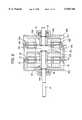
- FIG. 2is an axial-sectional view illustrating a coreless BLDC motor of a double rotor/stator-type according to a first embodiment of the present invention
- FIG. 3is a plane view of a rotor depicted in FIG. 2;
- FIGS. 4A and 4Bare respectively plane and side views illustrating a rotor of a modified example of the first embodiment of the present invention
- FIG. 5is a partial exploded perspective view illustrating a method for assembling the motor depicted in FIG. 2;
- FIG. 6is a sectional view illustrating a coreless BLDC motor of a dual-stage double-rotor/stator-type which is a modified example of the first embodiment of the present invention
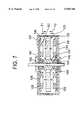
- FIG. 7is an axial-sectional view illustrating a coreless-type BLDC motor of a double stator-type according to a second embodiment of the present invention.
- FIG. 8is a sectional view illustrating a coreless-type BLDC motor of a dual-stage double-stator-type which is a modified example of the second embodiment of the present invention
- FIGS. 9A and 9Bare respectively a plane view of a stator assembly of a bobbin-type according to a third embodiment of the present invention and a sectional view taken along line A--A of FIG. 9A;
- FIG. 10is a partial axial-sectional view illustrating a coreless-type BLDC motor of a single double-rotor/single stator-type in which a stator assembly of the third embodiment is used;
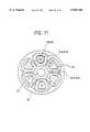
- FIG. 11is a diagram showing an alignment of stator coils and rotor magnets both of which are depicted in FIG. 10;
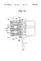
- FIG. 12is a partial axial-sectional view illustrating a coreless-type BLDC motor of a dual-stage double-rotor/stator-type which is a modified example of the third embodiment of the present invention
- FIGS. 13A, 13B, and 13Care respectively top plan, side elevation, and bottom plan views of a fourth embodiment of the invention.
- FIG. 14is a partial axial-sectional view illustrating a coreless-type BLDC motor of a double rotor/single stator type in which the stator assembly according to the fourth embodiment is used;
- FIG. 15is an axial-sectional view illustrating a coreless-type BLDC of a dual-stage double rotor/single stator-type according to a fourth embodiment of the present invention.
- FIG. 16is a partial cutaway sectional view illustrating a modified example of the motor case
- FIGS. 17A and 17Bare grapes each illustrating the amount of the oscillation of a conventional single rotor BLDC motor and a double rotor/stator BLDC motor according to the present invention respectively;
- FIG. 18is an axial-sectional view illustrating a double rotor BLDC motor having an air cooling structure according to the fifth embodiment of the present invention.
- FIG. 19a schematic plane view illustrating an arrangement of the magnet and a magnet yoke provided with magnetic flux leak holes
- FIG. 20is a graph illustrating a temperature of a condenser and a transistor according to a driving time when a closed-type drive motor is used.
- FIG. 21is a graph illustrating a temperature of a condenser and a transistor according to a driving time when an air cooling motor of the fifth embodiment is used.
- motordenotes a coreless brushless direct-current (BLDC) motor throughout the specification of the present invention, and it should be understood that the present invention is applicable to the other motors as well as the coreless BLDC motor.
- BLDCbrushless direct-current
- a BLDC motor of a first preferred embodimentincludes first and second stators 27 and 29 that are provided to both sides of a printed circuit board 21 fixed between left and right cases 20A and 20B and each have a plurality of bobbinless stator coils 25 and 26; and first and second rotors 33 and 35 which are provided to the left of the first stator 27 and the right of the second stator 29, respectively.
- each of the first and second rotors 33 and 35is configured in an annular-shape and comprised of a yoke 37 and a field magnet 5 with the N and S poles 5A and 5B alternately magnetized.
- the first and second stators 27 and 29have the same structure as each other.
- the first stator 27comprises three stator coils 25 which are coiled around the left side of the printed circuit board 21, in a fan-shape, in a bobbinless manner and are connected to each other in a Y-configuration manner.
- the first statorcomprises two stator coils 25 which are series-connected to each other.
- the second stator 29has stator coils 26 which are also mounted on the right side of the printed circuit board 21 in the same manner as that of the stator coils 25.
- stator coils 25are separated into six coils, and in the two-phase drive manner, two stator coils 25 are separated into eight coils.
- the coiling and electric current flow directions of the first and second stator coils 25 and 26are determined such that if the corresponding magnets of the first and second rotors 33 and 35 have the same pole as each other, the direction of the magnetic force of the first stator coils 25 is established to be opposite to that of the second stator coil 26.
- coil yokesare disposed between the printed circuit board 21 and the coils 25 and 26 to avoid offset magnetic circuit affection.
- the first and second coils 25 and 26are mounted such that their directions of coiling and electric current flow are established so that the magnetic force directions of them have the same magnetic flux direction as each other.
- Central portions of the left and right cases 20A and 20Bare rotatably connected to the rotating shaft 31 of the rotors 33 and 35 through respectively left and right bearings 39 and 41.
- a pair of E-ring 43A and 43Bare coupled between a bushing 23 and the bearings 39 and 41 so as to fix the bushing 23.
- a connector 44is fixed on one side of the printed circuit board 21 so as to supply a drive current to the stator coils 25 and 26.
- each of the rotors 33 and 35has a magnet structure which can be configured having an annular-shape with a multi-polarized magnetized magnets as shown in FIG. 3.
- the magnet structurecan be also configured having an annular-shape with a plurality of separate magnets which are multi-polarized as shown in FIGS. 4A and 4B.
- the separate magnet structurehas four separate north pole magnets 45A, 45B, 45C and 45D and four separate south pole magnets 45E, 45F, 45G and 45H, all of which are inserted into a support 47 made of a non-magnetic material.
- Such a separate magnet structurehas an advantage in that the manufacturing cost can be reduced since a portion which does not affect on the operation of the rotor is made of the non-magnetic material.
- FIG. 5there is shown a partial cut-away sectional view illustrating a method for assembling the motor according to the first embodiment of the present invention.
- the rotating shaft 31 on which the E-ring 43A and the bushing 23 for supporting the first rotor 33 are mountedis first coupled to the left case 20A provided with the left bearing 39 on its central concave portion, and then the printed circuit board 21 on which the first and second stators 27 and 29 are mounted is assembled.
- the bushing on which the second rotor 35 is fixedis coupled to the rotating shaft 31 and then fixed by the E-ring 43B.
- the right case 20B on which the right bearing 41 is fixedis assembled and fixed on the printed circuit board 21.
- the first and second stators 27 and 29 for driving the first and second rotors 33 and 35, respectively,are symmetrically disposed between the first and second rotors 33 and 35.
- the coiling and electric current flow directions of the corresponding coils 25 and 26 of the first and second stators 27 and 29are established such that the magnetic flux directions of them can be the same as each other or opposite to each other.
- the above described double rotor/stator structurehas the field magnet and the stator coil, each of which is made in an double structure, the current flowing along the coil and the magnetic flux density become two times the single stator structure, thereby increasing drive torque and output of the motor as much as two times those of the single stator.
- the vibrationdecreases.
- FIG. 6there is shown a two-stage sectional view illustrating a two-stage double-rotor/stator BLDC motor according to a first embodiment of the present invention.
- a two-stage BLDC motorAs shown in drawing, there is provided a two-stage BLDC motor.
- E-rings 43A and 43Bare coupled to opposite ends of the bushing 23, respectively.
- E-rings 43C and 43Dare respectively coupled to opposite ends of the bushing 23A.
- a medium case 20Cis further provided between left and right cases 20A and 20B.
- this two-stage double-rotor/stator BLDC motoris the same as that of the single BLDC motor depicted in FIG. 2, the description thereof will be omitted herein.
- FIG. 7illustrates a coreless BLDC motor of a double stator-type according to a second embodiment of the present invention.
- the coreless BLDC motor according to this second embodimentincludes a rotor 123 having a plurality of magnets 45A through 45H inserted into a support 47, and upper and lower stators 127 and 129 respectively disposed on upper and lower sides of the rotor and having bobbinless stator coils 125 and 126 each respectively mounted thereon.
- the rotor 123is fixedly carried on the rotating shaft 133 through a bushing 131, and, as shown in FIGS. 4A and 4B, has four N-pole magnets 45A through 45D and four S-pole magnets 45E through 45H all of which are inserted into the support 47 which is made of a non-magnetic material.
- the rotor 123may have an integrated multi-polar magnetized structure as shown in FIG. 3.
- the upper and lower stators 127 and 129have the same structure as each other.
- the upper stator 127comprises three stator coils 125 which are coiled around an upper printed circuit board 129 and are connected to each other in a Y-configuration manner.
- the upper stator 127comprises two stator coils 125 which are series connected to each other.
- the printed circuit board 135 on which the upper stator coil 125 are woundis fixed on a concave portion 139 formed on the inner side of the upper case 137, and the printed circuit board 141 is fixed on a concave portion 145.
- the central portions of the upper and lower cases 137 and 143are rotatably coupled around the rotating shaft 133 of the rotor 123 through upper and lower bearings 147 and 149.
- a leaf spring 151is disposed between the lower bearing 149 and the lower case 143 to damp an up-and-down vibration of the rotor.
- the upper and lower stators 127 and 129 for rotating the rotor 123are in a symmetry relation and the corresponding upper and lower stator coils 125 and 126 facing each other have coiling and current flow directions so that their magnetic flux directions are opposite to each other.
- the above described double stator structure of this second embodimenthas the stator coil which is made in an double structure, the current flowing along the coil and the magnetic flux density become two times the single stator structure, thereby increasing a drive torque as many as two times and the output of the motor.
- FIG. 8shows a two-stage BLDC motor according to a second embodiment.
- the two-stage BLDC motor of the second embodimentdiffers from the single stage BLDC motor in that it has a two-stage structure along the axial direction and E-rings 153 and 153A are coupled to upper and lower sides of bushings 131 and 131A.
- This two-stage structureprovides a motor having the larger displacement while minimizing the vibration in the axial direction.
- FIGS. 9A and 9Bshow a bobbin-type stator assembly according to a third embodiment of the present invention.
- the bobbin-type stator assembly 51comprises six bobbins 53 on which coils 55 are wound. These bobbins coils 55 are formed by insert molding method in an annular-shape by a resin insulating material, the coils 55 being connected each other on an auxiliary printed circuit board 57.
- Each central portion of the auxiliary printed circuit board 87 and the stator body 59is provided with a penetrating hole 61.
- an upper terminal 63A for electrically connecting this stator assembly to a control printed circuit board 87 depicted in FIG. 10 and a lower terminal 63B for electrically connecting this stator assembly to another stator assembly when a multiple stacked structure is adaptedare formed.
- the above described stator assemblycomprises, when a three-phase drive manner is used, three stator coils 55 which are coiled around the bobbins 53 each having a hole 65 in a fan-shape and are connected to each other in a Y-configuration manner at the printed circuit board 57, and, when a two-phase drive manner is used, comprises two stator coils 25 which are series connected to each other.
- each of the bobbin coils 55is not wound by a exclusive winder and a plastic bobbin 53 is used, a single or multiple axial winder which is easy to automatize can be used to wind the bobbin coils 55, thereby minimizing the manufacturing cost by reducing the expense for facility investment.
- the coils for the bobbin coil 55can be selected from a normal insulating copper wire which is chipper than the bonding wire used for the bobbinless coil by 25% to 50%, reducing the expense for the coil.
- each bobbin coil 55is sealed by resin insulating material, the insulation between the coils 55 can be enhanced as well as the damp-proof.
- stator assemblyis structured such that the coil 55 is wound around the bobbin and molded in an annular-shape, the mechanical strength can be increased as compared to the conventional one which is designed such that each coil is attached on both sides of the printed circuit board by an adhesive.
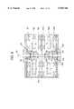
- FIG. 10shows a coreless-type BLDC motor of a single stage double rotor/single stator-type in which a stator assembly of the third embodiment is used
- FIG. 11shows an arrangement of stator coils and rotor magnets both of which are depicted in FIG. 10.
- the BLDC motorcomprises a control printed circuit board 87 which is mounted inside the motor, and the stator coil 55 which is wound around a bobbin 53 and formed in an annular-shape.
- the motorcomprises upper and lower cases 71A and 71B defining a cylindrical case with a stator assembly 51 having an outer circumference 67 extending upward and downward and coupled between the upper and lower cases 71A and 71B.
- Upper and lower rotors 73A and 73B each having a maget dividing multi-polarity arrangement structureare fixedly coupled around the rotating shaft 77 through bushings 75A and 75b at upper and lower portions of the stator assembly 51.
- the respective rotors 73A and 73Bhave eight magnets 81A and 81B. That is, four disk-type N-polar magnets and four disk-type S-polar magnets are alternately supported on a support 79 integrally formed with the bushings 75A and 75B and made of a polyethylene terephthalate or polybutylene terephthalate, and, on its one side, annular-shaped magnetic yokes 83A and 83B are integrally attached, thereby forming a magnetic circuit with respect to the eight magnets 81.
- the arrangement of the magnets 81A and 81B and the coils 55 of the stator assembly 51is illustrated in FIG. 11.
- the oblique lined annular-shaped magnets 81A and 81Bare disposed corresponding to the penetrating Halls 65 of the coils 55.
- An auxiliary magnet 85 for detecting the location of the Hall elementis attached on the upper surface of the yoke 83A of the upper rotor 73A.
- the auxiliary magnet 85is disposed opposing to the Hall element 89 of the printed circuit board 87 mounted on an inner circumference of the upper case 71A.
- a female connector 91 to which the upper terminal 63A of the stator assembly 51 is forcedly-coupledis mounted on one side of the control printed circuit board 87.
- Upper and lower bearings 93A and 93Bare fixed on central concave portions of the upper and lower cases 71A and 71B, respectively.
- the rotating shaft 77 of the rotors 73A and 73Bis rotatably supported through the bearings 93A and 93B.
- the reference numerals 95 and 97indicate respectively a distance maintaining bushing and a screw for fixing the upper and lower cases 71A and 71B.
- the BLDC motor according to the third embodimentforms a magnetic field in a predetermined direction when a drive current is applied to the stator coil 55 from the printed circuit board 87 through the upper terminal 63A.
- the repulsive forces F1 or attractions F2are offset since they act in the opposite direction to each other. As a result, when the rotors 73A and 73B rotate, the axial vibration thereof can be minimized.
- This motor according to the third embodimenthas the same output efficiency as that of the second embodiment.
- this third embodiment motoris structured such that the stator is constituted in a single body and the coil is assembled by using the bobbin, the productivity can be increased and the manufacturing cost can be decreased. In addition, since the overall supporting strength of the motor can be increased, endurance thereof is enhanced.
- control printed circuit board 87is mounted inside the motor case, it is possible to make the motor compact and to apply the motor to the various application.
- FIG. 12shows a two-stage BLDC motor according to a third embodiment of the present invention.
- the BLDC motorincludes two stator assemblies 51A and 51B. Upper and lower sides of each of the stator assemblies 51A and 51B are surrounded by double rotors 73A, 73B, 73C and 73D.
- this two-stage BLDC motorSince the operation of this two-stage BLDC motor is the same as that of the one-stage BLDC motor, the description thereof will be omitted herein.
- FIGS. 13A and 13Bshow a stator assembly according to a fourth embodiment of the present invention.
- bobbinless coils 255are used instead of the bobbin coils described in the third embodiment.
- the bobbinless coils 255are integrally formed on the stator assembly 251 in an insert molding manner.
- bobbinless coils 255are attached on an annular short ring 257A made of a conductive material to connect netural point of the bobbinless coils 255 to each other and an annular auxiliary printed circular board 157B by using an assembling jig.
- the coil assemblyis mounted on the stator body 259B with an annular stator holder 259A in the insert molding manner, thereby completing the assembly of the stator assembly 251.
- stator holder 259Ais provided with upper terminals 263A and lower terminals 263B connected to the upper terminals.
- the stator holder 259Ais further provided with a plurality of Halls 297A for bolt-coupling to the motor case.
- the stator holder 259Ais further provided with a key groove 253A and a projection key 253B to provide an automatic alignment when it is assembled with a motor case or a stator of another stage.
- the air gapis reduced by 1 mm.
- output and efficiencycan be increased to 4%.
- FIG. 14shows a coreless-type BLDC motor of a one-stage double rotor/single stator type in which the stator assembly according to the fourth embodiment is used
- FIG. 15illustrates a coreless-type BLDC of a two-stage double rotor/single stator-type according to a fourth embodiment of the present invention.
- the motor depicted in FIG. 16comprises a case which is made of a synthetic resin so as to reduce the weight thereof.
- the upper case 71Acan be made of resin material like the stator holder.
- the upper caseis provided at its one side with a hole to discharge heat created in an IC or TR module which is mounted on the upper surface of the printed circuit board 87.
- a l circular plate 103functioning as a heat sink by contacting the power IC 99 at its lower surface is joined by a plurality of bolts 97.
- the size of the formercan be reduced to 50% while the weight can be reduced by 1/3 as described hereinbelow.
- the rotormay be structurized having an integrated multi-polar magnetized structure depicted in FIG. 3, and the number of bobbinless stator coils mounted on the stator printed circuit board can be varied in accordance with the motor drive manners.
- the output of the motorcan be easily increased by increasing the stacked stage number of the motor.
- the key groove and the projection keyare also applicable to the first to third embodiments, and the assembling method of the fourth embodiment can be used for the third embodiment.
- Vibration pickup and amplifying portionsKEYENCE GA-245
- DC power sourceHANIL ELECTRONIC CO 303 B
- the motor of the present inventionwhen being subjected to a load, has a load current less than that of the prior motor. This means that consumption power of the present motor is remarkably reduced as compared with of the prior motor.
- the load rpm of the present motoris higher than that of the prior motor. This means that the torque of the present motor is distinctly increased as compared with the prior motor.
- FIG. 17Bshows that the vibration amount of the present motor is reduced to half that of the prior motor illustrated in FIG. 17A.
- the above described motors according to the first to fourth embodimentsuse a closed case.
- a fifth embodimentan air cooling structure for solving a heat discharging problem caused by the closed case) is explained.
- FIG. 18shows a double rotor BLDC motor according to the fifth embodiment, in which the motor has an air cooling structure
- FIG. 19shows an aligning of magnets and magnet yokes each provided with magnetic leakage holes.
- the motor according the fifth embodimenthas the same operation as that of the fourth embodiment. Therefore, the same reference numbers are used in FIG. 18 to refer to the same or like parts depicted in FIG. 14 illustrating the fourth embodiment.
- the reference numbers 51, 55, 57, 59, 61, 63, 65, 67, 71A, 71B, 73A, 73B, 77, 79, 87, 89, 91, and 97indicate a stator, coil, auxiliary printed circuit board, stator body, hole, connecting terminal, hole, outer circumference of the stator, upper case, lower case, upper rotor, lower rotor, rotating shaft, support, control printed circuit board, Hall element, connecting terminal, and screw, respectively.
- the reference numbers 75A and 75Brepresent bushings
- 81A and 81Brepresent magnets
- 83A and 83Bindicate magnet yokes
- 93A and 93Brepresent upper and lower bearings.
- a plurality of ventilating holes 311, 313, 315are provided to the upper and lower cases 71A and 71B and the control printed circuit board 87. Additional ventilating holes 317A and 317B corresponding to the ventilating holes 311, 313 and 315 are magnet yokes 83A and 83E of the upper and lower rotors 73A and 73B, and the support 79.
- the auxiliary magnet for detecting the location of the Hall elementis omitted by the arrangement of the ventilating holes 317A and 317B while the mounting location of the Hall element 89 is shifted.
- a magnetic leakage hole 319is formed on the magnet yoke 83A facing the Hall element 89, thereby allowing the Hall element 89 to detect leakage magnetic flux.
- the ventilating holes 311, 313, 315, 317A and 317Bare formed at the predetermined same distance along the circumference. To increase heat discharging efficiency, the ventilating holes 317A and 317B are formed inclining to an inside or to a rotating direction.
- a plurality of ventilating holes 321A and 321Bare formed to exhaust air induced into the motor through the ventilating holes 311, 313, 315, 317A and 317B.
- a stator drive signalis induced from a control integrated circuit and an output transistor 323 to the stator coil 55 through the connecting terminals 91 and 63A.
- an appropriate diameter D1should be determined by the following formula:
- the D2is a diameter of the printed circuit board of the and the D3 is an inner diameter of the magnet.
- the temperatures T1, T2 and T3 of the stator coil, condenser and transistor with respect to a voltage, current, and rpmare illustrated in Table 3.
- the temperatures T1, T2 and T3are respectively maintained at maximum temperatures of 61.8° C., 67.9° C. and 66.0° C.
- Table 4illustrates the temperatures T1A, T2A and T3A of the stator coil, condenser and transistor with respect to a voltage, current, and rpm of a closed motor. As can be seen in FIG. 20, even when continuously operating the motor for 30 minutes, the temperatures T1A, T2A and T3A are respectively increased to 100° C., 123.0° C., 145.0° C. and then abruptly dropt.
- the fifth embodimentmaintains that the temperature T3 of the transistor is about 67° C. even if continuously operation the motor for 5 hours, but the transistor of the closed motor has failed at the time of 36 minutes.
- the motorcan be maintained at a relatively lower temperature, thereby preventing the output reduction and thermal runaway of the output transistor.
Landscapes
- Engineering & Computer Science (AREA)
- Power Engineering (AREA)
- Microelectronics & Electronic Packaging (AREA)
- Permanent Magnet Type Synchronous Machine (AREA)
- Windings For Motors And Generators (AREA)
- Brushless Motors (AREA)
- Insulation, Fastening Of Motor, Generator Windings (AREA)
Abstract
Description
TABLE 1 ______________________________________ Size(Diameter × Output Length) Weight (W) (mm) (kg) Remark ______________________________________ Core-type 30 92 × 60 1.4 Having internal BLDC motorcontrol PCB Present 30 92 × 35 0.5 Having internal invention motor control PCB ______________________________________
TABLE 2 ______________________________________ Electrical characteristic Present invention Prior art (FIG. 1) ______________________________________ No-Load current 400 mA 75 mA Load current 700 mA 1.1 A No-load RPM 1230 rpm 1651 rpm Load RPM 930 rpm 850 rpm ______________________________________
D1=(D2-D3)-2
TABLE 3 ______________________________________ Voltage Current Coil Condenser TR Time T: (° C.) (V) (mA) RPM (T1) (T2) (T3) (min) Remark ______________________________________ 43 850 1380 29 28 28 0 43 900 1380 42 43 51 10 43 900 1376 51.5 49.4 58.3 20 43 900 1385 55.9 52.8 61.9 30 43 900 1383 57.7 54.3 63.6 40 43 910 1390 59.3 55.0 64.7 50 43 900 1380 60.3 56 65.5 60 43 900 1385 60.8 56.6 66.0 100 43 900 1384 60.9 57.0 66.2 120 43 900 1385 60.8 57.3 66.3 140 43 910 1390 61.4 57.9 66.9 160 43 900 1380 60.6 56.6 66.9 180 43 910 1385 61.1 56.4 66.9 210 43 910 1387 61.8 56.7 66.3 230 43 910 1392 61.2 56.6 66.7 250 43 910 1386 61.1 56.8 66.3 370 ______________________________________
TABLE 4 ______________________________________ Voltage Current Coil Condenser TR Time T: (° C.) (V) (mA) RPM (T1) (T2) (T3) (min) Remark ______________________________________ 43 950 1330 26.6 26.4 27 0 43 1000 1330 47.9 87.6 78.7 10 43 1100 1323 64.0 108.2 99.6 20 43 920 1330 74.0 113.0 121.7 30 43 960 1325 78.5 145.0 123.0 33 43 1000 1330 69.9 85.0 77.7 36 TR broken ______________________________________
Claims (14)
Priority Applications (3)
| Application Number | Priority Date | Filing Date | Title |
|---|---|---|---|
| US08/783,908US5945766A (en) | 1996-01-18 | 1997-01-16 | Coreless-type BLDC motor and method of producing stator assembly having axial vibration attenuation arrangement |
| JP9-19921AJP3005487B2 (en) | 1996-10-09 | 1997-01-17 | Coreless brushless DC motor with double rotor / single stator system |
| DE19701797ADE19701797A1 (en) | 1996-01-18 | 1997-01-20 | Coreless and brushless double-rotor type DC motor with stator group mfg method |
Applications Claiming Priority (5)
| Application Number | Priority Date | Filing Date | Title |
|---|---|---|---|
| KR1019960000977AKR100213573B1 (en) | 1996-01-18 | 1996-01-18 | Double rotor type coreless BCD motor |
| KR1019960000976AKR100213572B1 (en) | 1996-01-18 | 1996-01-18 | Double stator and coress-type bldc motor |
| KR1019960018767AKR100213571B1 (en) | 1996-05-30 | 1996-05-30 | Double rotor/single stator and coreless-type bldc motor using one-body type stator |
| KR2019960033202UKR200146527Y1 (en) | 1996-10-09 | 1996-10-09 | Bldc motor of double rotor system having air cooling structure |
| US08/783,908US5945766A (en) | 1996-01-18 | 1997-01-16 | Coreless-type BLDC motor and method of producing stator assembly having axial vibration attenuation arrangement |
Publications (1)
| Publication Number | Publication Date |
|---|---|
| US5945766Atrue US5945766A (en) | 1999-08-31 |
Family
ID=27532190
Family Applications (1)
| Application Number | Title | Priority Date | Filing Date |
|---|---|---|---|
| US08/783,908Expired - Fee RelatedUS5945766A (en) | 1996-01-18 | 1997-01-16 | Coreless-type BLDC motor and method of producing stator assembly having axial vibration attenuation arrangement |
Country Status (2)
| Country | Link |
|---|---|
| US (1) | US5945766A (en) |
| DE (1) | DE19701797A1 (en) |
Cited By (74)
| Publication number | Priority date | Publication date | Assignee | Title |
|---|---|---|---|---|
| WO2001084695A1 (en)* | 2000-04-28 | 2001-11-08 | Genius Ingenieur-Gesellschaft Mbh | Electrical machine comprising disc rotors |
| US6368592B1 (en) | 1998-07-17 | 2002-04-09 | Massachusetts Institute Of Technology | Method of delivering oxygen to cells by electrolyzing water |
| US6376954B1 (en)* | 1997-12-11 | 2002-04-23 | Empresa Brasileira De Compressores S./A -Sembraco | Hermetic compressor for a refrigeration system |
| US6437529B1 (en)* | 1998-05-04 | 2002-08-20 | Comair Rotron, Inc. | Multi-stator motor with independent stator circuits |
| US6439855B1 (en) | 2001-02-12 | 2002-08-27 | Siemens Automotive, Inc. | Direct current electric motor which eliminates outer case and places brushes and chokes in space efficient locations |
| US20030117029A1 (en)* | 2001-12-20 | 2003-06-26 | Sunonwealth Electric Machine Industry Co., Ltd. | Electric power connections structure of a direct current motor |
| WO2004004098A1 (en) | 2002-06-26 | 2004-01-08 | Amotech Co., Ltd. | Brushless direct-current motor of radial core type having a structure of double rotors and method for making the same |
| US6707207B1 (en)* | 2002-12-19 | 2004-03-16 | Hitachi Global Storage Technologies Netherlands B.V. | High bandwidth track following actuator for hard disk drives |
| US6720688B1 (en)* | 1999-02-12 | 2004-04-13 | Helmut Schiller | Electric machine |
| US20040075358A1 (en)* | 2002-02-12 | 2004-04-22 | Hisayuki Furuse | Electric rotating machine |
| RU2251784C1 (en)* | 2003-11-19 | 2005-05-10 | Государственное образовательное учреждение высшего профессионального образования "Санкт-Петербургский государственный морской технический университет" | Flanged multilayer torque motor |
| US20050146233A1 (en)* | 2004-01-06 | 2005-07-07 | Canon Kabushiki Kaisha | Actuator, light quantity adjusting apparatus, and stepping motor |
| US20060071576A1 (en)* | 2002-09-27 | 2006-04-06 | Yun-Hyun Cho | Flat board type brushless dc motor |
| US7078844B2 (en)* | 2003-11-20 | 2006-07-18 | Delta Electronics, Inc. | Heat-dissipating device and motor structure thereof |
| US7084548B1 (en)* | 2003-07-11 | 2006-08-01 | Gabrys Christopher W | Low cost high speed electrical machine |
| US20060244320A1 (en)* | 2005-04-29 | 2006-11-02 | Dong-Liang Guo | Brushless motor having coreless assembly |
| US20060270326A1 (en)* | 2005-03-25 | 2006-11-30 | Min-Huang Lin | Handiwork instrument using coreless brushless motor |
| EP1729396A1 (en)* | 2005-06-03 | 2006-12-06 | Fujitsu General Limited | Axial air gap type electric motor |
| US20060279166A1 (en)* | 2004-05-18 | 2006-12-14 | Seiko Epson Corporation | Motor |
| US20060279162A1 (en)* | 2005-05-17 | 2006-12-14 | Achor Kyle D | BLDC motor and pump assembly with encapsulated circuit board |
| US20070022830A1 (en)* | 2005-07-29 | 2007-02-01 | Mandziuk Michael W | ID-OD discrimination sensor |
| WO2005089327A3 (en)* | 2004-03-14 | 2007-04-12 | Revolution Electric Motor Comp | Commercial low cost, high efficiency motor-generator |
| US20070152536A1 (en)* | 2006-01-03 | 2007-07-05 | Delta Electronics, Inc. | Three-phase opposite rotating motor and fan |
| WO2008014112A2 (en) | 2006-07-26 | 2008-01-31 | Palmer Robert A | Electric motor |
| US20080028596A1 (en)* | 2006-08-01 | 2008-02-07 | Achor Kyle D | System and method for manufacturing a brushless dc motor fluid pump |
| US20080136282A1 (en)* | 2004-12-24 | 2008-06-12 | Sumitomo Electric Industries, Ltd. | Axial Gap Type Motor |
| WO2008091035A1 (en)* | 2007-01-25 | 2008-07-31 | Tae Chang N.E.T. Co., Ltd. | Afpm coreless multi-generator and motor |
| US20080197728A1 (en)* | 2005-06-15 | 2008-08-21 | Sonceboz Sa | Rotary Single-Phase Electromagnetic Servo Actuator Comprising an Actuator and a Position Sensor |
| US20080265816A1 (en)* | 2007-04-26 | 2008-10-30 | Seiko Epson Corporation | Brushless electric machine |
| US20080278018A1 (en)* | 2007-05-09 | 2008-11-13 | Kyle Dean Achor | Bldc motor assembly |
| US20090072083A1 (en)* | 2006-06-02 | 2009-03-19 | Honeywell International, Inc. | Actuation system with redundant motor actuators |
| US20090085412A1 (en)* | 2007-10-02 | 2009-04-02 | Seiko Epson Corporation | Brushless electric machine |
| US7573173B1 (en)* | 2007-09-28 | 2009-08-11 | Aximet Technology, Inc. | Apparatus for axial magnetic field electric motor |
| US20100019593A1 (en)* | 2004-08-12 | 2010-01-28 | Exro Technologies Inc. | Polyphasic multi-coil generator |
| US20100072932A1 (en)* | 2008-07-31 | 2010-03-25 | Eric Seger | Fail-Passive Electro-Mechanical Actuator Utilizing Dual Controllers And A Two-Phase Brushless Motor |
| US20100090553A1 (en)* | 2006-06-08 | 2010-04-15 | Exro Technologies Inc. | Polyphasic multi-coil generator |
| US20100141060A1 (en)* | 2005-07-28 | 2010-06-10 | Toru Okazaki | Axial motor |
| US20100164313A1 (en)* | 2007-05-03 | 2010-07-01 | In Motion Technologies Pty Limited | Axial flux electrical machine |
| US7750515B1 (en)* | 2005-10-25 | 2010-07-06 | Gabrys Christopher W | Industrial air core motor-generator |
| US20100201214A1 (en)* | 2009-02-10 | 2010-08-12 | Sanyo Denki Co., Ltd. | Small-sized motor |
| US20100253173A1 (en)* | 2007-09-14 | 2010-10-07 | Koji Miyata | Axial gap type coreless rotating machine |
| US7812500B1 (en)* | 2008-11-12 | 2010-10-12 | Demetrius Calvin Ham | Generator / electric motor |
| WO2011018811A1 (en)* | 2009-08-11 | 2011-02-17 | Enatek S.R.L. | An electric alternator for wind power generators |
| CN101710767B (en)* | 2009-12-03 | 2012-02-22 | 胡润行 | Intelligent permanent magnetic wind driven generator |
| US20120169161A1 (en)* | 2009-09-21 | 2012-07-05 | Kyoung-Sik Woo | Disk motor using a permanent magnet and bypassing the magnetic force of the magnet |
| CN101295908B (en)* | 2007-04-26 | 2012-09-05 | 精工爱普生株式会社 | Brushless Motor |
| US20120228967A1 (en)* | 2011-03-08 | 2012-09-13 | Wealth Marching International Limited | Electric Motor |
| CN102723827A (en)* | 2012-07-09 | 2012-10-10 | 罗寿元 | Special pure electric vehicle coaxial combination brushless DC motor with functions of power self-regulating and temperature control |
| US20120326541A1 (en)* | 2008-08-15 | 2012-12-27 | Millennial Research Corporation | Regenerative Motor and Coil |
| CN103066782A (en)* | 2012-11-01 | 2013-04-24 | 北京理工大学 | Magnetoelectricity type micro generator |
| US20130221776A1 (en)* | 2011-01-18 | 2013-08-29 | Mitsubishi Electric Corporation | Electric power steering electric motor apparatus and electric power steering apparatus |
| CN103457424A (en)* | 2013-05-17 | 2013-12-18 | 湖南大学 | Double-rotor iron-core-free permanent-magnet synchronous motor |
| US20130342084A1 (en)* | 2012-06-26 | 2013-12-26 | Wei-Chung Su | Motor with internal driver |
| US20150015108A1 (en)* | 2013-07-12 | 2015-01-15 | Kabushiki Kaisha Toshiba | Axial gap type permanent magnet electric rotating apparatus and method of manufacturing the same |
| US20150194252A1 (en)* | 2014-01-08 | 2015-07-09 | Honeywell International Inc. | Torque motor actuator with an armature stop |
| US20150380992A1 (en)* | 2013-01-23 | 2015-12-31 | Hitachi ,Ltd. | Axial Gap-Type Electric Rotating Machine |
| EP2133981A3 (en)* | 2008-06-12 | 2017-06-14 | General Electric Company | High torque density electrical machine |
| US9979268B2 (en) | 2014-08-01 | 2018-05-22 | Panasonic Intellectual Property Management Co., Ltd. | Motor |
| US10038349B2 (en) | 2008-08-15 | 2018-07-31 | Millennial Research Corporation | Multi-phase modular coil element for electric motor and generator |
| WO2019045665A1 (en)* | 2017-08-29 | 2019-03-07 | Lukashenko Gennadii | Direct current motor with a powered stator |
| EP3189584B1 (en)* | 2014-09-02 | 2019-11-06 | Cicilia, Beremundo Elsio | Synchronous rotation motor or generator provided with diverse rotors and/or stators |
| DE102019202630A1 (en)* | 2019-02-27 | 2020-08-27 | Fraunhofer-Gesellschaft zur Förderung der angewandten Forschung e.V. | Electric motor |
| US11018537B2 (en) | 2015-05-19 | 2021-05-25 | Time To Act Limited | Method of construction for permanent magnet generator |
| US11081996B2 (en) | 2017-05-23 | 2021-08-03 | Dpm Technologies Inc. | Variable coil configuration system control, apparatus and method |
| US11089931B2 (en) | 2017-03-06 | 2021-08-17 | Samsung Electronics Co., Ltd. | Fan unit and cleaner having the same |
| US20210351652A1 (en)* | 2019-07-05 | 2021-11-11 | Renwei YU | Flat-type stator with multilayer coils for disc-type motor |
| US11223263B2 (en)* | 2016-12-02 | 2022-01-11 | Time To Act Limited | Rotary generators |
| US20220239173A1 (en)* | 2019-05-17 | 2022-07-28 | Time To Act Limited | Improvements to the construction of axial flux rotary generators |
| US20230163663A1 (en)* | 2021-10-26 | 2023-05-25 | Lifetrons Switzerland Holdings Limited | Energy-saving brushless motor-kinetic generator with energy-saving function |
| US11708005B2 (en) | 2021-05-04 | 2023-07-25 | Exro Technologies Inc. | Systems and methods for individual control of a plurality of battery cells |
| US11722026B2 (en) | 2019-04-23 | 2023-08-08 | Dpm Technologies Inc. | Fault tolerant rotating electric machine |
| US11770048B2 (en) | 2013-10-18 | 2023-09-26 | Black & Decker, Inc. | Handheld power tool with a brushless electric motor |
| US11967913B2 (en) | 2021-05-13 | 2024-04-23 | Exro Technologies Inc. | Method and apparatus to drive coils of a multiphase electric machine |
| US12176836B2 (en) | 2018-09-05 | 2024-12-24 | Dpm Technologies Inc. | Systems and methods for intelligent energy storage and provisioning using an energy storage control system |
Families Citing this family (8)
| Publication number | Priority date | Publication date | Assignee | Title |
|---|---|---|---|---|
| RU2141158C1 (en)* | 1998-07-30 | 1999-11-10 | Автономная некоммерческая организация Центр экономического развития "МОНОТРОН" | Face-mounted permanent-magnet torque motor |
| RU2141159C1 (en)* | 1998-07-30 | 1999-11-10 | Автономная некоммерческая организация Центр экономического развития "МОНОТРОН" | Permanent-magnet torque motor |
| DE29821126U1 (en) | 1998-11-25 | 1999-01-21 | Müller, Michael, 51377 Leverkusen | Electromagnetic axial machine |
| DE10140362A1 (en)* | 2001-08-17 | 2003-03-06 | Yu-Fang Fan | Side rotated motor or generator includes stator, two rotators formed on the top and bottom sides of the stator, a shaft, a plurality of bearings and fixing devices |
| DE10311817A1 (en)* | 2003-03-13 | 2004-10-07 | Minebea Co., Ltd. | Electric motor especially brushless electric motor, has stator units embedded in cured embedding compound which forms carrier body for stator units |
| DE10311818A1 (en)* | 2003-03-13 | 2004-09-30 | Minebea Co., Ltd. | Electric motor has housing parts forming segment containing stator units, carrying first, second closure elements on first, second ends so it can engage first closure element of another housing part |
| DE102007004359A1 (en)* | 2007-01-29 | 2008-07-31 | Ortloff, Helene | Device for controlling direct current motor, has coil elements, which are arranged partially in star-connection with different windings and has neutral point, where windings and neutral point are connected to a computer unit |
| CN109301977B (en)* | 2018-11-30 | 2024-03-08 | 重庆长基科技有限公司 | Outer rotor brushless slotless motor |
Citations (18)
| Publication number | Priority date | Publication date | Assignee | Title |
|---|---|---|---|---|
| US1566693A (en)* | 1925-12-22 | Otto pletscher | ||
| US3579277A (en)* | 1968-04-30 | 1971-05-18 | Suwa Seikosha Kk | Brushless direct current motor |
| US3953751A (en)* | 1971-09-01 | 1976-04-27 | Papst Motoren Kg | Motor and mounting thereof |
| US3999092A (en)* | 1974-04-04 | 1976-12-21 | Canadian General Electric Company Limited | Permanent magnet synchronous dynamoelectric machine |
| US4007390A (en)* | 1973-07-26 | 1977-02-08 | Papst-Motoren Kg | Brushless D-C motor |
| US4072881A (en)* | 1975-11-06 | 1978-02-07 | Itsuki Ban | Axial-air-gap type semiconductor electric motor |
| US4187441A (en)* | 1977-03-23 | 1980-02-05 | General Electric Company | High power density brushless dc motor |
| US4517484A (en)* | 1982-02-18 | 1985-05-14 | Ateliers De Constructions Electriques De Charleroi (Acec) | Double gap electric generating machines |
| US4536672A (en)* | 1983-08-12 | 1985-08-20 | Nippondenso Co., Ltd. | Flat type rotary electric machine |
| US4578606A (en)* | 1984-12-13 | 1986-03-25 | Buehler Products, Inc. | Brushless DC electric motor and tachogenerator assembly |
| US4629920A (en)* | 1983-10-03 | 1986-12-16 | Mavilor Systeme Sa | Alternating current synchronous servomotor |
| US4633149A (en)* | 1985-09-10 | 1986-12-30 | Buehler Products, Inc. | Brushless DC motor |
| US4961017A (en)* | 1987-09-28 | 1990-10-02 | Akai Electric Co., Ltd. | Stator for use in a brushless motor |
| US5057726A (en)* | 1990-10-10 | 1991-10-15 | Westinghouse Electric Corp. | Structureborne vibration-compensated motor arrangement having back-to-back twin AC motors |
| US5289069A (en)* | 1990-08-29 | 1994-02-22 | Matsushita Electric Industrial Co., Ltd. | Brushless motor |
| US5440185A (en)* | 1991-10-28 | 1995-08-08 | Allwine, Jr.; Elmer C. | Composite magnet brushless DC motor |
| US5610457A (en)* | 1994-02-07 | 1997-03-11 | Kabushiki Kaisha Sankyo Seiki Seisakusho | Brushless motor with hall elements for controlling drive circuit and for detecting a position of rotor by use of magnetic flux varying means |
| US5623178A (en)* | 1993-07-19 | 1997-04-22 | Toyota Jidosha Kabushiki Kaisha | Coil structure for electric motor |
Family Cites Families (9)
| Publication number | Priority date | Publication date | Assignee | Title |
|---|---|---|---|---|
| DE1563418A1 (en)* | 1966-09-30 | 1970-05-21 | Siemens Ag | Brushless DC motor |
| DE2802753C2 (en)* | 1978-01-23 | 1987-02-12 | Herbert Prof. Dr.-Ing. 3300 Braunschweig Weh | Synchronous machine |
| JPS5615257U (en)* | 1979-07-11 | 1981-02-09 | ||
| JPS60102856A (en)* | 1983-11-05 | 1985-06-07 | Fanuc Ltd | Ac servomotor |
| FR2562347B1 (en)* | 1984-04-02 | 1988-07-15 | Sfim | DRIVE MOTOR FOR GYROSCOPE, METHOD FOR MANUFACTURING SAME, AND GYROSCOPE COMPRISING SUCH A MOTOR |
| JPS6392250A (en)* | 1986-10-07 | 1988-04-22 | Nippon Chemicon Corp | Brushless motor of thin type |
| JPH07118897B2 (en)* | 1986-10-23 | 1995-12-18 | 株式会社東芝 | Motor manufacturing method |
| DE4229261C1 (en)* | 1992-09-02 | 1994-03-31 | August Mutter | Electric generator for bicycle or individual wheel with rotor at rotatable wheel - equipped with permanent magnets and stator formed by coil system for receiving induced voltage is fixed on wheel spindle and generator can be used as servo motor |
| DE4238886A1 (en)* | 1992-11-19 | 1994-05-26 | Papst Minebea Disc Motor Gmbh | Disc store automatic data storage disc prodn. with disc(s) in flat housing - from composite with inner and outer layers of soft magnetic steel sheet and core of flexible plastics with integrated circuitry |
- 1997
- 1997-01-16USUS08/783,908patent/US5945766A/ennot_activeExpired - Fee Related
- 1997-01-20DEDE19701797Apatent/DE19701797A1/ennot_activeCeased
Patent Citations (18)
| Publication number | Priority date | Publication date | Assignee | Title |
|---|---|---|---|---|
| US1566693A (en)* | 1925-12-22 | Otto pletscher | ||
| US3579277A (en)* | 1968-04-30 | 1971-05-18 | Suwa Seikosha Kk | Brushless direct current motor |
| US3953751A (en)* | 1971-09-01 | 1976-04-27 | Papst Motoren Kg | Motor and mounting thereof |
| US4007390A (en)* | 1973-07-26 | 1977-02-08 | Papst-Motoren Kg | Brushless D-C motor |
| US3999092A (en)* | 1974-04-04 | 1976-12-21 | Canadian General Electric Company Limited | Permanent magnet synchronous dynamoelectric machine |
| US4072881A (en)* | 1975-11-06 | 1978-02-07 | Itsuki Ban | Axial-air-gap type semiconductor electric motor |
| US4187441A (en)* | 1977-03-23 | 1980-02-05 | General Electric Company | High power density brushless dc motor |
| US4517484A (en)* | 1982-02-18 | 1985-05-14 | Ateliers De Constructions Electriques De Charleroi (Acec) | Double gap electric generating machines |
| US4536672A (en)* | 1983-08-12 | 1985-08-20 | Nippondenso Co., Ltd. | Flat type rotary electric machine |
| US4629920A (en)* | 1983-10-03 | 1986-12-16 | Mavilor Systeme Sa | Alternating current synchronous servomotor |
| US4578606A (en)* | 1984-12-13 | 1986-03-25 | Buehler Products, Inc. | Brushless DC electric motor and tachogenerator assembly |
| US4633149A (en)* | 1985-09-10 | 1986-12-30 | Buehler Products, Inc. | Brushless DC motor |
| US4961017A (en)* | 1987-09-28 | 1990-10-02 | Akai Electric Co., Ltd. | Stator for use in a brushless motor |
| US5289069A (en)* | 1990-08-29 | 1994-02-22 | Matsushita Electric Industrial Co., Ltd. | Brushless motor |
| US5057726A (en)* | 1990-10-10 | 1991-10-15 | Westinghouse Electric Corp. | Structureborne vibration-compensated motor arrangement having back-to-back twin AC motors |
| US5440185A (en)* | 1991-10-28 | 1995-08-08 | Allwine, Jr.; Elmer C. | Composite magnet brushless DC motor |
| US5623178A (en)* | 1993-07-19 | 1997-04-22 | Toyota Jidosha Kabushiki Kaisha | Coil structure for electric motor |
| US5610457A (en)* | 1994-02-07 | 1997-03-11 | Kabushiki Kaisha Sankyo Seiki Seisakusho | Brushless motor with hall elements for controlling drive circuit and for detecting a position of rotor by use of magnetic flux varying means |
Cited By (133)
| Publication number | Priority date | Publication date | Assignee | Title |
|---|---|---|---|---|
| US6376954B1 (en)* | 1997-12-11 | 2002-04-23 | Empresa Brasileira De Compressores S./A -Sembraco | Hermetic compressor for a refrigeration system |
| US6437529B1 (en)* | 1998-05-04 | 2002-08-20 | Comair Rotron, Inc. | Multi-stator motor with independent stator circuits |
| US6368592B1 (en) | 1998-07-17 | 2002-04-09 | Massachusetts Institute Of Technology | Method of delivering oxygen to cells by electrolyzing water |
| US6720688B1 (en)* | 1999-02-12 | 2004-04-13 | Helmut Schiller | Electric machine |
| WO2001084695A1 (en)* | 2000-04-28 | 2001-11-08 | Genius Ingenieur-Gesellschaft Mbh | Electrical machine comprising disc rotors |
| US6439855B1 (en) | 2001-02-12 | 2002-08-27 | Siemens Automotive, Inc. | Direct current electric motor which eliminates outer case and places brushes and chokes in space efficient locations |
| US20030117029A1 (en)* | 2001-12-20 | 2003-06-26 | Sunonwealth Electric Machine Industry Co., Ltd. | Electric power connections structure of a direct current motor |
| US6608412B2 (en)* | 2001-12-20 | 2003-08-19 | Sunonwealth Electric Machine Industry Co., Ltd. | Electric power connection structure of a direct current motor |
| US20040075358A1 (en)* | 2002-02-12 | 2004-04-22 | Hisayuki Furuse | Electric rotating machine |
| US6943473B2 (en)* | 2002-02-12 | 2005-09-13 | Nissan Motor Co., Ltd. | Electric rotating machine |
| WO2004004098A1 (en) | 2002-06-26 | 2004-01-08 | Amotech Co., Ltd. | Brushless direct-current motor of radial core type having a structure of double rotors and method for making the same |
| US20060071576A1 (en)* | 2002-09-27 | 2006-04-06 | Yun-Hyun Cho | Flat board type brushless dc motor |
| US6707207B1 (en)* | 2002-12-19 | 2004-03-16 | Hitachi Global Storage Technologies Netherlands B.V. | High bandwidth track following actuator for hard disk drives |
| US7084548B1 (en)* | 2003-07-11 | 2006-08-01 | Gabrys Christopher W | Low cost high speed electrical machine |
| RU2251784C1 (en)* | 2003-11-19 | 2005-05-10 | Государственное образовательное учреждение высшего профессионального образования "Санкт-Петербургский государственный морской технический университет" | Flanged multilayer torque motor |
| US7078844B2 (en)* | 2003-11-20 | 2006-07-18 | Delta Electronics, Inc. | Heat-dissipating device and motor structure thereof |
| US20050146233A1 (en)* | 2004-01-06 | 2005-07-07 | Canon Kabushiki Kaisha | Actuator, light quantity adjusting apparatus, and stepping motor |
| US20060186742A1 (en)* | 2004-01-06 | 2006-08-24 | Canon Kabushiki Kaisha | Actuator, light quantity adjusting apparatus, and stepping motor |
| US7242123B2 (en) | 2004-01-06 | 2007-07-10 | Canon Kabushiki Kaisha | Actuator, light quantity adjusting apparatus, and stepping motor |
| US7148592B2 (en)* | 2004-01-06 | 2006-12-12 | Canon Kabushiki Kaisha | Actuator, light quantity adjusting apparatus, and stepping motor |
| CN101019298B (en)* | 2004-03-14 | 2011-02-09 | 瑞佛路申电动机有限公司 | Brushless motor-generator and its production method |
| WO2005089327A3 (en)* | 2004-03-14 | 2007-04-12 | Revolution Electric Motor Comp | Commercial low cost, high efficiency motor-generator |
| US7884517B2 (en) | 2004-05-18 | 2011-02-08 | Seiko Epson Corporation | Electric machine |
| EP1646130A4 (en)* | 2004-05-18 | 2008-03-05 | Seiko Epson Corp | ENGINE |
| US20090160383A1 (en)* | 2004-05-18 | 2009-06-25 | Seiko Epson Corporation | Electric machine |
| EP2264874A3 (en)* | 2004-05-18 | 2015-04-29 | Seiko Epson Corporation | Electric machine |
| US20060279166A1 (en)* | 2004-05-18 | 2006-12-14 | Seiko Epson Corporation | Motor |
| US7501733B2 (en) | 2004-05-18 | 2009-03-10 | Seiko Epson Corporation | Electric machine |
| US9685827B2 (en) | 2004-08-12 | 2017-06-20 | Exro Technologies Inc. | Polyphasic multi-coil electric device |
| US8212445B2 (en)* | 2004-08-12 | 2012-07-03 | Exro Technologies Inc. | Polyphasic multi-coil electric device |
| US8614529B2 (en) | 2004-08-12 | 2013-12-24 | Exro Technologies, Inc. | Polyphasic multi-coil electric device |
| US20100019593A1 (en)* | 2004-08-12 | 2010-01-28 | Exro Technologies Inc. | Polyphasic multi-coil generator |
| US7821169B2 (en)* | 2004-12-24 | 2010-10-26 | Sumitomo Electric Industries, Ltd. | Axial gap type motor |
| US20080136282A1 (en)* | 2004-12-24 | 2008-06-12 | Sumitomo Electric Industries, Ltd. | Axial Gap Type Motor |
| US20060270326A1 (en)* | 2005-03-25 | 2006-11-30 | Min-Huang Lin | Handiwork instrument using coreless brushless motor |
| US20060244320A1 (en)* | 2005-04-29 | 2006-11-02 | Dong-Liang Guo | Brushless motor having coreless assembly |
| US7411326B2 (en) | 2005-05-17 | 2008-08-12 | Federal Mogul World Wide, Inc. | BLDC motor and pump assembly with encapsulated circuit board |
| US20060279162A1 (en)* | 2005-05-17 | 2006-12-14 | Achor Kyle D | BLDC motor and pump assembly with encapsulated circuit board |
| KR100893239B1 (en) | 2005-06-03 | 2009-04-10 | 가부시키가이샤 후지츠 제네랄 | Axial air-gap electronic motor |
| EP1729396A1 (en)* | 2005-06-03 | 2006-12-06 | Fujitsu General Limited | Axial air gap type electric motor |
| US7554226B2 (en) | 2005-06-03 | 2009-06-30 | Fujitsu General Limited | Axial air gap type electric motor |
| US20060279150A1 (en)* | 2005-06-03 | 2006-12-14 | Fujitsu General Limited | Axial air gap type electric motor |
| US20080197728A1 (en)* | 2005-06-15 | 2008-08-21 | Sonceboz Sa | Rotary Single-Phase Electromagnetic Servo Actuator Comprising an Actuator and a Position Sensor |
| US8222777B2 (en)* | 2005-06-15 | 2012-07-17 | Sonceboz Sa | Rotary single-phase electromagnetic servo actuator comprising an actuator and a position sensor |
| US8502426B2 (en) | 2005-06-15 | 2013-08-06 | Sonceboz Sa | Rotary single-phase electromagnetic servo actuator comprising an actuator and a position sensor |
| US7791246B2 (en)* | 2005-07-28 | 2010-09-07 | Sumitomo Electric Industries, Ltd. | Axial motor |
| US20100141060A1 (en)* | 2005-07-28 | 2010-06-10 | Toru Okazaki | Axial motor |
| US7256576B2 (en)* | 2005-07-29 | 2007-08-14 | General Electric Company | ID-OD discrimination sensor |
| US20070022830A1 (en)* | 2005-07-29 | 2007-02-01 | Mandziuk Michael W | ID-OD discrimination sensor |
| US7750515B1 (en)* | 2005-10-25 | 2010-07-06 | Gabrys Christopher W | Industrial air core motor-generator |
| US20070152536A1 (en)* | 2006-01-03 | 2007-07-05 | Delta Electronics, Inc. | Three-phase opposite rotating motor and fan |
| US7525228B2 (en)* | 2006-01-03 | 2009-04-28 | Delta Electronics, Inc. | Three-phase opposite rotating motor and fan |
| US20090072083A1 (en)* | 2006-06-02 | 2009-03-19 | Honeywell International, Inc. | Actuation system with redundant motor actuators |
| US8106563B2 (en) | 2006-06-08 | 2012-01-31 | Exro Technologies Inc. | Polyphasic multi-coil electric device |
| US9584056B2 (en) | 2006-06-08 | 2017-02-28 | Exro Technologies Inc. | Polyphasic multi-coil generator |
| US20100090553A1 (en)* | 2006-06-08 | 2010-04-15 | Exro Technologies Inc. | Polyphasic multi-coil generator |
| EP2070182A4 (en)* | 2006-07-26 | 2013-01-09 | Robert A Palmer | Electric motor |
| WO2008014112A2 (en) | 2006-07-26 | 2008-01-31 | Palmer Robert A | Electric motor |
| US8853907B2 (en) | 2006-07-26 | 2014-10-07 | Millennial Research Corporation | Electric motor |
| US20080028596A1 (en)* | 2006-08-01 | 2008-02-07 | Achor Kyle D | System and method for manufacturing a brushless dc motor fluid pump |
| US7931448B2 (en) | 2006-08-01 | 2011-04-26 | Federal Mogul World Wide, Inc. | System and method for manufacturing a brushless DC motor fluid pump |
| AU2007344715B2 (en)* | 2007-01-25 | 2010-10-28 | Tae Chang N.E.T. Co., Ltd. | AFPM coreless multi-generator and motor |
| US8264107B2 (en)* | 2007-01-25 | 2012-09-11 | In-Ho Jee | AFPM coreless multi-generator and motor |
| WO2008091035A1 (en)* | 2007-01-25 | 2008-07-31 | Tae Chang N.E.T. Co., Ltd. | Afpm coreless multi-generator and motor |
| US20090309430A1 (en)* | 2007-01-25 | 2009-12-17 | In-Ho Jee | Afpm coreless multi-generator and motor |
| US8080967B2 (en) | 2007-04-26 | 2011-12-20 | Seiko Epson Corporation | Brushless electric machine |
| US7906930B2 (en) | 2007-04-26 | 2011-03-15 | Seiko Epson Corporation | Brushless electric machine |
| US20120062162A1 (en)* | 2007-04-26 | 2012-03-15 | Seiko Epson Corporation | Brushless electric machine |
| US20110101902A1 (en)* | 2007-04-26 | 2011-05-05 | Seiko Epson Corporation | Brushless electric machine |
| CN101295908B (en)* | 2007-04-26 | 2012-09-05 | 精工爱普生株式会社 | Brushless Motor |
| US8581459B2 (en) | 2007-04-26 | 2013-11-12 | Seiko Epson Corporation | Brushless electric machine |
| US20080265816A1 (en)* | 2007-04-26 | 2008-10-30 | Seiko Epson Corporation | Brushless electric machine |
| US8319469B2 (en)* | 2007-04-26 | 2012-11-27 | Seiko Epson Corporation | Brushless electric machine |
| US20100164313A1 (en)* | 2007-05-03 | 2010-07-01 | In Motion Technologies Pty Limited | Axial flux electrical machine |
| US9041264B2 (en)* | 2007-05-03 | 2015-05-26 | Regal Beloit America, Inc. | Axial flux electrical machine |
| US20110057531A1 (en)* | 2007-05-09 | 2011-03-10 | Kyle Dean Achor | BLDC Motor Assembly |
| US8291574B2 (en) | 2007-05-09 | 2012-10-23 | Federal-Mogul World Wide Inc. | Method of making a BLDC motor assembly |
| US8987964B2 (en) | 2007-05-09 | 2015-03-24 | Carter Fuel Systems, Llc | Permanent magnet segment for use with a BLDC motor assembly |
| US7847457B2 (en) | 2007-05-09 | 2010-12-07 | Federal-Mogul World Wide, Inc | BLDC motor assembly |
| US20080278018A1 (en)* | 2007-05-09 | 2008-11-13 | Kyle Dean Achor | Bldc motor assembly |
| TWI415367B (en)* | 2007-09-14 | 2013-11-11 | Shinetsu Chemical Co | Axial clearance type without core rotating machine |
| US8299676B2 (en)* | 2007-09-14 | 2012-10-30 | Shin-Etsu Chemical Co., Ltd. | Axial gap type coreless rotating machine |
| US20100253173A1 (en)* | 2007-09-14 | 2010-10-07 | Koji Miyata | Axial gap type coreless rotating machine |
| US7573173B1 (en)* | 2007-09-28 | 2009-08-11 | Aximet Technology, Inc. | Apparatus for axial magnetic field electric motor |
| US7986069B2 (en) | 2007-10-02 | 2011-07-26 | Seiko Epson Corporation | Brushless electric machine |
| US20090085412A1 (en)* | 2007-10-02 | 2009-04-02 | Seiko Epson Corporation | Brushless electric machine |
| US20110084565A1 (en)* | 2007-10-02 | 2011-04-14 | Seiko Epson Corporation | Brushless electric machine |
| US8102090B2 (en) | 2007-10-02 | 2012-01-24 | Seiko Epson Corporation | Brushless electric machine |
| US7880356B2 (en) | 2007-10-02 | 2011-02-01 | Seiko Epson Corporation | Brushless electric machine |
| EP2133981A3 (en)* | 2008-06-12 | 2017-06-14 | General Electric Company | High torque density electrical machine |
| US20100072932A1 (en)* | 2008-07-31 | 2010-03-25 | Eric Seger | Fail-Passive Electro-Mechanical Actuator Utilizing Dual Controllers And A Two-Phase Brushless Motor |
| US20120326541A1 (en)* | 2008-08-15 | 2012-12-27 | Millennial Research Corporation | Regenerative Motor and Coil |
| US9800111B2 (en)* | 2008-08-15 | 2017-10-24 | Millennial Research Corporation | Regenerative motor and coil |
| US10038349B2 (en) | 2008-08-15 | 2018-07-31 | Millennial Research Corporation | Multi-phase modular coil element for electric motor and generator |
| US7812500B1 (en)* | 2008-11-12 | 2010-10-12 | Demetrius Calvin Ham | Generator / electric motor |
| TWI474584B (en)* | 2009-02-10 | 2015-02-21 | Sanyo Electric Co | Small-sized motor |
| US8283822B2 (en)* | 2009-02-10 | 2012-10-09 | Sanyo Denki Co., Ltd. | Small-sized motor |
| US20100201214A1 (en)* | 2009-02-10 | 2010-08-12 | Sanyo Denki Co., Ltd. | Small-sized motor |
| WO2011018811A1 (en)* | 2009-08-11 | 2011-02-17 | Enatek S.R.L. | An electric alternator for wind power generators |
| US20120169161A1 (en)* | 2009-09-21 | 2012-07-05 | Kyoung-Sik Woo | Disk motor using a permanent magnet and bypassing the magnetic force of the magnet |
| CN101710767B (en)* | 2009-12-03 | 2012-02-22 | 胡润行 | Intelligent permanent magnetic wind driven generator |
| US20130221776A1 (en)* | 2011-01-18 | 2013-08-29 | Mitsubishi Electric Corporation | Electric power steering electric motor apparatus and electric power steering apparatus |
| US9391486B2 (en)* | 2011-01-18 | 2016-07-12 | Mitsubishi Electric Corporation | Electric power steering electric motor apparatus and electric power steering apparatus |
| US20120228967A1 (en)* | 2011-03-08 | 2012-09-13 | Wealth Marching International Limited | Electric Motor |
| US8836188B2 (en)* | 2012-06-26 | 2014-09-16 | Yen Shen Electronic Ind. Co., Ltd. | Motor with internal driver |
| US20130342084A1 (en)* | 2012-06-26 | 2013-12-26 | Wei-Chung Su | Motor with internal driver |
| CN102723827B (en)* | 2012-07-09 | 2014-05-07 | 河北弛神电机制造有限公司 | Special pure electric vehicle coaxial combination brushless DC motor with functions of power self-regulating and temperature control |
| CN102723827A (en)* | 2012-07-09 | 2012-10-10 | 罗寿元 | Special pure electric vehicle coaxial combination brushless DC motor with functions of power self-regulating and temperature control |
| CN103066782A (en)* | 2012-11-01 | 2013-04-24 | 北京理工大学 | Magnetoelectricity type micro generator |
| US20150380992A1 (en)* | 2013-01-23 | 2015-12-31 | Hitachi ,Ltd. | Axial Gap-Type Electric Rotating Machine |
| CN103457424A (en)* | 2013-05-17 | 2013-12-18 | 湖南大学 | Double-rotor iron-core-free permanent-magnet synchronous motor |
| US9337709B2 (en)* | 2013-07-12 | 2016-05-10 | Kabushiki Kaisha Toshiba | Axial gap type permanent magnet electric rotating apparatus and method of manufacturing the same |
| US20150015108A1 (en)* | 2013-07-12 | 2015-01-15 | Kabushiki Kaisha Toshiba | Axial gap type permanent magnet electric rotating apparatus and method of manufacturing the same |
| US11770048B2 (en) | 2013-10-18 | 2023-09-26 | Black & Decker, Inc. | Handheld power tool with a brushless electric motor |
| US9711269B2 (en)* | 2014-01-08 | 2017-07-18 | Honeywell International Inc. | Torque motor actuator with an armature stop |
| US20150194252A1 (en)* | 2014-01-08 | 2015-07-09 | Honeywell International Inc. | Torque motor actuator with an armature stop |
| US9979268B2 (en) | 2014-08-01 | 2018-05-22 | Panasonic Intellectual Property Management Co., Ltd. | Motor |
| EP3189584B1 (en)* | 2014-09-02 | 2019-11-06 | Cicilia, Beremundo Elsio | Synchronous rotation motor or generator provided with diverse rotors and/or stators |
| US11018537B2 (en) | 2015-05-19 | 2021-05-25 | Time To Act Limited | Method of construction for permanent magnet generator |
| US11223263B2 (en)* | 2016-12-02 | 2022-01-11 | Time To Act Limited | Rotary generators |
| EP3549244B1 (en)* | 2016-12-02 | 2024-06-19 | Time To Act Plc | Improvements to rotary generators |
| US11089931B2 (en) | 2017-03-06 | 2021-08-17 | Samsung Electronics Co., Ltd. | Fan unit and cleaner having the same |
| US11081996B2 (en) | 2017-05-23 | 2021-08-03 | Dpm Technologies Inc. | Variable coil configuration system control, apparatus and method |
| WO2019045665A1 (en)* | 2017-08-29 | 2019-03-07 | Lukashenko Gennadii | Direct current motor with a powered stator |
| US12176836B2 (en) | 2018-09-05 | 2024-12-24 | Dpm Technologies Inc. | Systems and methods for intelligent energy storage and provisioning using an energy storage control system |
| DE102019202630A1 (en)* | 2019-02-27 | 2020-08-27 | Fraunhofer-Gesellschaft zur Förderung der angewandten Forschung e.V. | Electric motor |
| US11722026B2 (en) | 2019-04-23 | 2023-08-08 | Dpm Technologies Inc. | Fault tolerant rotating electric machine |
| US20220239173A1 (en)* | 2019-05-17 | 2022-07-28 | Time To Act Limited | Improvements to the construction of axial flux rotary generators |
| US11909284B2 (en)* | 2019-07-05 | 2024-02-20 | Renwei YU | Flat-type stator with multilayer coils for disc-type motor |
| US20210351652A1 (en)* | 2019-07-05 | 2021-11-11 | Renwei YU | Flat-type stator with multilayer coils for disc-type motor |
| US11708005B2 (en) | 2021-05-04 | 2023-07-25 | Exro Technologies Inc. | Systems and methods for individual control of a plurality of battery cells |
| US11967913B2 (en) | 2021-05-13 | 2024-04-23 | Exro Technologies Inc. | Method and apparatus to drive coils of a multiphase electric machine |
| US20230163663A1 (en)* | 2021-10-26 | 2023-05-25 | Lifetrons Switzerland Holdings Limited | Energy-saving brushless motor-kinetic generator with energy-saving function |
Also Published As
| Publication number | Publication date |
|---|---|
| JPH09327163A (en) | 1997-12-16 |
| DE19701797A1 (en) | 1997-07-24 |
Similar Documents
| Publication | Publication Date | Title |
|---|---|---|
| US5945766A (en) | Coreless-type BLDC motor and method of producing stator assembly having axial vibration attenuation arrangement | |
| US7443074B2 (en) | Apparatus for driving drum of washing machine | |
| US4891567A (en) | Brushless DC motor having an outer rotor | |
| US4130769A (en) | Brushless DC motor | |
| EP1414132B1 (en) | Electric motor, method of fabricating the same, and hermetic compressor comprising the same | |
| US5852335A (en) | Stator structure for rotary electric machine | |
| EP1923981B1 (en) | Axail air gap type electric motor | |
| CN110048566B (en) | Dual-rotor coreless electromagnetic motor | |
| EP1923982A2 (en) | Axial air gap type electric motor | |
| KR20180054087A (en) | Vehicle fan-motor using one-body type stator | |
| US20010013732A1 (en) | Anti-vibration electric motor having outer rotor stably supported at two ends | |
| KR100213572B1 (en) | Double stator and coress-type bldc motor | |
| US6064133A (en) | Built-in stator of star-winding mechanism and method of producing the stator and BLDC motor using the same | |
| KR100213571B1 (en) | Double rotor/single stator and coreless-type bldc motor using one-body type stator | |
| US20190222083A1 (en) | Electric motor with a dual rotor and a bobbin-less stator | |
| KR101079050B1 (en) | Stator having structure of division type skew core, BLDC motor using the same, and battery cooling apparatus | |
| US20190222082A1 (en) | Universal electromagnetic machine | |
| US5739620A (en) | Optimum groove/pole ratio for brushless motor stator profile | |
| JP3005487B2 (en) | Coreless brushless DC motor with double rotor / single stator system | |
| KR100213573B1 (en) | Double rotor type coreless BCD motor | |
| KR200146527Y1 (en) | Bldc motor of double rotor system having air cooling structure | |
| JP7543229B2 (en) | Stator core for axial gap type rotating electric machine, and method for manufacturing stator for axial gap type rotating electric machine | |
| CN110034615B (en) | electromagnetic machine | |
| JPH0426342A (en) | single phase synchronous fan motor | |
| JPS60162431A (en) | Fan motor |
Legal Events
| Date | Code | Title | Description |
|---|---|---|---|
| AS | Assignment | Owner name:AMOTRON CO., LTD., KOREA, REPUBLIC OF Free format text:ASSIGNMENT OF ASSIGNORS INTEREST;ASSIGNORS:KIM, BYUNGKYU;KIM, JOON;KIM, DONGHOON;AND OTHERS;REEL/FRAME:008397/0619 Effective date:19970109 Owner name:YUYU CO., LTD, KOREA, REPUBLIC OF Free format text:ASSIGNMENT OF ASSIGNORS INTEREST;ASSIGNORS:KIM, BYUNGKYU;KIM, JOON;KIM, DONGHOON;AND OTHERS;REEL/FRAME:008397/0619 Effective date:19970109 | |
| AS | Assignment | Owner name:AMOTRON CO., LTD., KOREA, REPUBLIC OF Free format text:ASSIGNMENT OF ASSIGNORS INTEREST;ASSIGNOR:YUYU CO., LTD.;REEL/FRAME:009880/0901 Effective date:19990311 | |
| FPAY | Fee payment | Year of fee payment:4 | |
| AS | Assignment | Owner name:AMOTECH CO., LTD., KOREA, REPUBLIC OF Free format text:MERGER;ASSIGNOR:AMOTRON CO., LTD.;REEL/FRAME:014172/0357 Effective date:20030325 | |
| FPAY | Fee payment | Year of fee payment:8 | |
| REMI | Maintenance fee reminder mailed | ||
| LAPS | Lapse for failure to pay maintenance fees | ||
| STCH | Information on status: patent discontinuation | Free format text:PATENT EXPIRED DUE TO NONPAYMENT OF MAINTENANCE FEES UNDER 37 CFR 1.362 | |
| FP | Lapsed due to failure to pay maintenance fee | Effective date:20110831 |