US5944859A - Hot gas filter and system assembly - Google Patents
Hot gas filter and system assemblyDownload PDFInfo
- Publication number
- US5944859A US5944859AUS08/642,203US64220396AUS5944859AUS 5944859 AUS5944859 AUS 5944859AUS 64220396 AUS64220396 AUS 64220396AUS 5944859 AUS5944859 AUS 5944859A
- Authority
- US
- United States
- Prior art keywords
- filter element
- gas
- filter
- porous
- walls
- Prior art date
- Legal status (The legal status is an assumption and is not a legal conclusion. Google has not performed a legal analysis and makes no representation as to the accuracy of the status listed.)
- Expired - Lifetime
Links
Images


Classifications
- B—PERFORMING OPERATIONS; TRANSPORTING
- B01—PHYSICAL OR CHEMICAL PROCESSES OR APPARATUS IN GENERAL
- B01D—SEPARATION
- B01D46/00—Filters or filtering processes specially modified for separating dispersed particles from gases or vapours
- B01D46/24—Particle separators, e.g. dust precipitators, using rigid hollow filter bodies
- B01D46/2403—Particle separators, e.g. dust precipitators, using rigid hollow filter bodies characterised by the physical shape or structure of the filtering element
- B01D46/2407—Filter candles
- B—PERFORMING OPERATIONS; TRANSPORTING
- B01—PHYSICAL OR CHEMICAL PROCESSES OR APPARATUS IN GENERAL
- B01D—SEPARATION
- B01D46/00—Filters or filtering processes specially modified for separating dispersed particles from gases or vapours
- B01D46/56—Filters or filtering processes specially modified for separating dispersed particles from gases or vapours with multiple filtering elements, characterised by their mutual disposition
- B01D46/58—Filters or filtering processes specially modified for separating dispersed particles from gases or vapours with multiple filtering elements, characterised by their mutual disposition connected in parallel
- B—PERFORMING OPERATIONS; TRANSPORTING
- B01—PHYSICAL OR CHEMICAL PROCESSES OR APPARATUS IN GENERAL
- B01D—SEPARATION
- B01D2265/00—Casings, housings or mounting for filters specially adapted for separating dispersed particles from gases or vapours
- B01D2265/06—Details of supporting structures for filtering material, e.g. cores
- B—PERFORMING OPERATIONS; TRANSPORTING
- B01—PHYSICAL OR CHEMICAL PROCESSES OR APPARATUS IN GENERAL
- B01D—SEPARATION
- B01D2271/00—Sealings for filters specially adapted for separating dispersed particles from gases or vapours
- B01D2271/02—Gaskets, sealings
- B—PERFORMING OPERATIONS; TRANSPORTING
- B01—PHYSICAL OR CHEMICAL PROCESSES OR APPARATUS IN GENERAL
- B01D—SEPARATION
- B01D2273/00—Operation of filters specially adapted for separating dispersed particles from gases or vapours
- B01D2273/20—High temperature filtration
- Y—GENERAL TAGGING OF NEW TECHNOLOGICAL DEVELOPMENTS; GENERAL TAGGING OF CROSS-SECTIONAL TECHNOLOGIES SPANNING OVER SEVERAL SECTIONS OF THE IPC; TECHNICAL SUBJECTS COVERED BY FORMER USPC CROSS-REFERENCE ART COLLECTIONS [XRACs] AND DIGESTS
- Y10—TECHNICAL SUBJECTS COVERED BY FORMER USPC
- Y10S—TECHNICAL SUBJECTS COVERED BY FORMER USPC CROSS-REFERENCE ART COLLECTIONS [XRACs] AND DIGESTS
- Y10S55/00—Gas separation
- Y10S55/12—Pocket type filter
Definitions
- This inventionrelates generally to high temperature gas cleanup systems and more particularly to a hot gas filter for filtering fine dirty particulates from a gas.
- Hot gas cleanup systemsthat are implemented to clean particulate matter from a gas stream are well known in the art. These systems are currently used to clean coal fired gas, (i.e. pressurized fluidized-bed combustion gas; gasification, applications), and waste incineration. Additionally, gas cleanup systems may be applied to catalyst and precious metal recovery, calcination, catalytic cracking, and material recovery during chemical processing.
- Conventional hot gas cleanup systemsgenerally comprise a filter assembly which is mounted within a pressure vessel having a clean gas side and a dirty gas side.
- the filter assemblyfurther comprises a plurality of filter element arrays, a tube sheet for supporting the filter element arrays, plenum pipes for channeling filtered clean gas to a desired location within the cleanup system, and a back pulse system for cleaning particulates from the outer surface of the filter elements.
- These systemsmay employ various types of filter elements to filter particulate matter from a gas stream.
- Typical filter elements employed to filter particulate matterinclude cross-flow filters, ceramic and/or sintered metal circular cylindrical filters (candle and/or tubular filters), and ceramic bag filters. These filter elements are generally mounted within a pressure vessel so that a hot gas can flow through the filter elements such that a substantial part of fine particulate matter within the process gas can be removed therefrom.
- fine particulatescollect on the outer surface of the filter elements while the clean gas flows through the filter media, into the plenum pipes, and out into the clean gas side of the pressure vessel.
- a substantial amount of the fine particulate matter that is collected on the outside of the filteris removed therefrom by a reverse gas pulse provided by the back pulse system.
- bridging of ash between adjacent filter elements and/or metal structurescan occur.
- the bridging of ashcan contribute to the failure or breakage of filter elements which would require that the entire system be shut down for days so that the filter elements can be replaced. It would therefore be desirable to provide a filter element and/or system that reduces the potential for bridging of ash.
- the present inventionembodies a filter element for separating fine dirty particles from a hot gas.
- the filter elementcomprises a first porous wall and a second porous wall. Each porous wall has an outer surface and an inner surface.
- the first and second porous wallsare coupled at a first closed end and open at a second end. The open end is formed to be coupled to a hot gas clean up system support structure.
- the first and second porous wallsdefine a channel beginning at the open end and terminate at the closed end through which a filtered clean gas can flow into the clean gas side of a hot gas cleaning system.
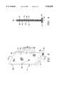
- FIG. 1is longitudinal view of a hot gas cleanup system
- FIG. 2is a perspective view of the hot gas cleanup system shown in FIG. 1 incorporating the preferred filter embodiment in accordance with the present invention
- FIG. 3is a perspective view of the preferred filter element in accordance with the present invention.
- FIG. 4is a sectional view taken along line 4--4 of the filter element shown in FIG. 3;
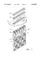
- FIG. 5is a perspective view of a filter support structure and filter assembly
- FIG. 6is an exploded view of the filter element shown in FIG. 4 and corresponding attachment assembly.
- FIG. 7is an exploded view of a tubesheet and the support structure assembly.
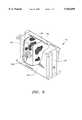
- FIG. 8is a perspective view of a fail-safe regenerator.
- FIGS. 1 and 2show a filtering apparatus for separating particulate matter from a dirty gas stream.
- the pressure vessel 20has a dome-shaped head 22 and a body 24.
- the dome-shaped head 22terminates in a linear tip defining an exit opening or nozzle 27 for the gas processed in the pressure vessel 20.
- the body 24includes a dirty gas inlet 25, an upper part 26 having a generally circular cylindrical shape joined by a frusto conical lower part 28 for receiving the particulate matter terminating in a linear tip defining an opening or nozzle 29 connected to an ash discharge line (not shown) for collecting particulate matter.
- the left 34 and right split tubesheet 36are shown dividing the pressure vessel 20 into a clean gas side 38 and a dirty gas side 40.
- the filter elements 44 in accordance with the present inventionare shown secured within the dirty gas side 40.
- the filter support structures and plenum pipe 42are shown attached to the corresponding split tubesheet 34, 36.
- the filter elements 44 in accordance with the present inventionare shown coupled to the support structures 42 within the dirty gas side 40 of the pressure vessel 20.
- the top of filter support structure plenum pipes 46 for channeling the filtered clean gas to the clean gas side 38 of the pressure vessel 20are shown coupled to the support bar 48 and the split tubesheet 34, 36.
- a plurality of ports 30extend from the dome-shaped head 22.
- the back pulse pipe assembly 32(back pulse system not shown) is coupled to the ports 30 to provide the necessary back pulse gas to clean or remove particulate matter from the filter elements 44.
- the filter element 44comprises a first porous wall 50 and a second porous wall 51.
- Each porous wallhas an outer surface 52, 53 and an inner surface 54, 55.
- Each wall 50, 51contains pores 56 that may range between about 1 micron to about 40 microns which permit a gas to flow through and prevent the particulate matter from passing through.
- the first and second porous wall outer surfaces 52, 53are preferably substantially flat, rigid, and seamless (not laminated). Alternately, each wall 50, 51 may contain pores that range between 1 micron to about 500-600 microns.
- an outer membrane 90, 92is applied to prevent particulate matter from passing through the first and second porous wall 50, 51.
- the first and second porous walls 50, 51are formed in communication with one another at a closed end 58 and remain open at an opposing support end 60, and by a left side wall 58a, and a right side wall 58b. It is preferable that the first and second porous walls 50, 51 be coupled at the closed end 58 such that the two porous walls remain substantially parallel to each other and define a channel 64.
- the support end 60is preferably formed in the shape of a flange 61 such that it can be supportingly coupled with the support structure plenum pipe 42 to secure the filter elements 44 within the pressure vessel 20 as shown in FIG. 2.
- the first and second porous walls 50, 51define a channel 64 beginning at the filter element open support end 60 and terminates at the filter element closed end 58.
- the channel 64provides a path through which the filtered clean gas can flow into the plenum pipes 42.
- the filter porous walls 50, 51can be formed in other flat ridged shapes or from porous walls that are sintered together to form laminated layers.
- the shape and size of the filter walls 50, 51may depend on the application for which the filter element 44 is used and the materials of construction. Some of the materials that can be employed to produce the filter element comprise a ceramic material, monolithic ceramic material, composite ceramic material, and sintered metal material.
- the present inventionmay provide a first and second porous wall formed to be of the barrier or bulk filter element type.
- the barrier type filter element porous wallsdefine pores 56 which permit gas to flow through and capture the particulate matter on the filter outer surface 52, 53.
- a bulk filter element in accordance with the present inventioncomprises a first and second porous wall which define pores that permit a gas to flow through.
- the bulk filter elementis formed such that particulate matter will collect on the filter outer surface 52, 53 and within the pores 56, thereby filling or restricting gas passage through the first and second porous walls 50, 51.
- At least one membrane layermay be applied to each of the filter embodiment outer surfaces, inner surfaces, or both surfaces.
- the membranewould provide additional filtering capabilities of the filters.
- the membrane layers 90, 92are provided to prevent particulate matter from penetrating the filter pores when either the back pulse system is activated or during normal gas flow.
- the filter membranecan be any material that can be applied to the filter element that would allow particulates to be filtered from a gas and allow process gas to flow through the filter element into the plenum pipes 42, or pulse cleaning gas through the porous filter walls 50, 51.
- each filter element support plenum pipe structure 42for supporting each filter element 44 within the pressure vessel 20 is shown.
- the plurality of filter element support plenum pipe structuresare rigidly positioned by a support bar 48.
- Each filter element support plenum pipe 42has sidewalls 110 having a plurality of slots 112 that are formed to be coupled with a filter element flange 61 and gasket assembly 120, 121.
- the filter element 44, and filter element support plenum pipe structure 42 arrangementpreferably provides a relative vertical chamber which allows ash to dislodge and fall unobstructed into the particulate nozzle 29.
- the plenum pipe sidewall 110defines an interior channel 114 through which filtered clean gas can flow into and to the clean side 38 of the pressure vessel 20, see FIG. 1.
- the support bar 48preferably has a C-shaped cross-section.
- FIG. 6shows the filter element attachment assembly 41 that is employed to secure each filter element 44 to the support structure 42 shown in FIG. 5.
- Each filter element 44is attached with at least one gasket or ceramic mat 116 positioned between the filter element flange support end 60, 61 and a rear bracket 118 and at least one gasket or ceramic mat 120 positioned above the filter element flange support end 60, 61 and a front bracket 122 to prevent gas from travelling past the filter element into the plenum pipe interior chamber 114 (shown in FIG. 5).
- one gasket or ceramic matis positioned between the rear bracket 118 and the sidewall 110 of the filter element support plenum pipe 42.
- the filter element 44, gaskets 116, 120, and brackets 118, 122are preferably coupled together with nuts 124 and bolts 126.
- the filter element support structure plenum pipe 42, support bar 48, split tubesheet 36, retaining ring 128 and dust ring 130are shown.
- the retaining rings 128 and dust rings 130are provided to prevent a gas from traveling past the split tubesheet 34, 36 and into the clean side 38 above the dome-shape head 22 of the vessel 20 shown in FIGS. 1 and 2.
- the support bar 48securely holds the filter element support structure plenum pipe 42 in alignment so that the corresponding split tubesheet 34, 36, retaining rings 128 and dust rings 130 can be securely mounted within the pressure vessel 20.
- the array of filter elements 44provide additional space between each filter element 44 relative to conventional filter element designs for a given vessel foot print, thereby, reducing the potential for ash formation between filter elements.
- a further advantage of this arrangementis an increased filter surface area through which the hot gas flows and is filtered within a defined vessel footprint.
- the filter arrangementalso provides easy maintainability, handling, and repair of filter elements.
- a fail-safe/regenerator 132may be employed with the filter support plenum pipe assembly 42 shown in FIG. 7.
- the fail-safe/regenerator 132is designed to be securely coupled adjacent to the filter element flange end 60 shown in FIGS. 3 and 4.
- the fail-safe/regenerator 132comprises a housing 134 which defines an interior chamber 144; a particulate barrier 136; and heating media, such as a box of heating pieces 138.
- the housing 134preferably has a generally rectangular shape that is formed to be coupled between the filter flange end 60 and the plenum pipe slot 112 shown in FIGS. 5 and 7.
- the housing 134has a gas flow inlet end 140 and outlet end 142.
- the inlet end 140is formed to be securely coupled adjacent the filter flange end 60, ceramic mat or gasket 116 and rear bracket 118 shown in FIG. 6.
- the outlet end 142directs clean gas through the plenum pipe 42 to the clean gas side 38 of the filter vessel.
- the particulate barrier 136is securely mounted between the inlet end 140 and outlet 142 end.
- the particulate barrier 136is preferably a metal screen, but can also be a ceramic felt mat, continuous fibers, reticulated foam monolithic ceramic thin filter, or ceramic composite thin filter.
- the particulate barrier 136is formed to allow clean gas and back pulse gas to flow through, and to also prevent ash from travelling into the clean gas side 38 of the system.
- the heating media or box of heating pieces 138is placed between the particulate barrier 136 and outlet end 142.
- the heating media or box of heating pieces 138are provided to heat the cooler back pulsed gas to prevent the filter element from enduring thermal shock or fatigue during pulse cleaning.
- the heating pieces 138are preferably made of a metal material, such as 310 stainless steel.
- the cleanup system in accordance with the present inventionpermits particulate laden gas to enter in through the dirty gas inlet 25. Particulates from the dirty gas collect on the outer surface 52, 53 of each filter element 44.
- the filtered clean gasproceeds through the porous filter walls 50, 51, through the filter element channel 64, and into the interior channel 114 of the plenum pipes 42.
- the gasproceeds through the plenum pipes 42 to the clean side 38 of the split tubesheets 34, 36.
- the clean gasthen proceeds through the dome gas outlet 27.
- the filter elements 44are cleaned by short blasts of compressed gas through the back pulse pipe assembly 32, which dislodges the particulates from the filter elements.
Landscapes
- Chemical & Material Sciences (AREA)
- Chemical Kinetics & Catalysis (AREA)
- Physics & Mathematics (AREA)
- Geometry (AREA)
- Filtering Of Dispersed Particles In Gases (AREA)
- Filtering Materials (AREA)
Abstract
Description
Claims (18)
Priority Applications (7)
| Application Number | Priority Date | Filing Date | Title |
|---|---|---|---|
| US08/642,203US5944859A (en) | 1996-05-06 | 1996-05-06 | Hot gas filter and system assembly |
| CA002253519ACA2253519C (en) | 1996-05-06 | 1997-04-28 | Hot gas filter and system assembly |
| EP97921390AEP0944422B1 (en) | 1996-05-06 | 1997-04-28 | Hot gas filter and system assembly |
| KR1019980708888AKR20000010766A (en) | 1996-05-06 | 1997-04-28 | High-temperature gas filter and system assembly |
| JP9539959AJP2000509647A (en) | 1996-05-06 | 1997-04-28 | High temperature gas filter and device assembly |
| DE69709167TDE69709167T2 (en) | 1996-05-06 | 1997-04-28 | Hot gas filter and assembly |
| PCT/US1997/006997WO1997041944A2 (en) | 1996-05-06 | 1997-04-28 | Hot gas filter and system assembly |
Applications Claiming Priority (1)
| Application Number | Priority Date | Filing Date | Title |
|---|---|---|---|
| US08/642,203US5944859A (en) | 1996-05-06 | 1996-05-06 | Hot gas filter and system assembly |
Publications (1)
| Publication Number | Publication Date |
|---|---|
| US5944859Atrue US5944859A (en) | 1999-08-31 |
Family
ID=24575637
Family Applications (1)
| Application Number | Title | Priority Date | Filing Date |
|---|---|---|---|
| US08/642,203Expired - LifetimeUS5944859A (en) | 1996-05-06 | 1996-05-06 | Hot gas filter and system assembly |
Country Status (7)
| Country | Link |
|---|---|
| US (1) | US5944859A (en) |
| EP (1) | EP0944422B1 (en) |
| JP (1) | JP2000509647A (en) |
| KR (1) | KR20000010766A (en) |
| CA (1) | CA2253519C (en) |
| DE (1) | DE69709167T2 (en) |
| WO (1) | WO1997041944A2 (en) |
Cited By (13)
| Publication number | Priority date | Publication date | Assignee | Title |
|---|---|---|---|---|
| WO2001045822A1 (en)* | 1999-12-20 | 2001-06-28 | Siemens Westinghouse Power Corporation | Tubular and honeycomb metal fail-safe regenerator filter devices |
| WO2001051176A1 (en)* | 2000-01-07 | 2001-07-19 | Siemens Westinghouse Power Corporation | Interlocked fiber fail-safe regenerator filter devices |
| US6428593B1 (en) | 2000-09-29 | 2002-08-06 | Siemens Westinghouse Power Corporation | Filter holder gasket assembly for enhanced securement of candle filters |
| US6468322B1 (en) | 2000-09-29 | 2002-10-22 | Siemens Westinghouse Power Corporation | Filter holder assembly having extended collar spacer ring |
| US6592641B2 (en) | 2001-09-19 | 2003-07-15 | Siemens Westinghouse Power Corporation | Integral porous filter/fail-safe/regenerator/gas separation membrane module |
| EP1495792A1 (en)* | 2003-07-11 | 2005-01-12 | PUREM Abgassysteme GmbH & Co. KG | Filter bag for an exhaust gas filter |
| US6863868B1 (en)* | 2000-09-29 | 2005-03-08 | Siemens Westinghouse Power Corporation | Catalytically enhanced filtration apparatus |
| US20050163673A1 (en)* | 2004-01-23 | 2005-07-28 | Johnson John T. | Fluidized-bed reactor system |
| US20080127827A1 (en)* | 2006-11-30 | 2008-06-05 | Raether Thomas D | Filter apparatus with pulse cleaning and methods for pulse cleaning filters |
| US20090184064A1 (en)* | 2008-01-23 | 2009-07-23 | Sohail Zaiter | Scalable immersed-filtration method and apparatus |
| US20100263337A1 (en)* | 2009-02-27 | 2010-10-21 | Donaldson Company, Inc | Filter cartridge; components thereof; and methods |
| US10625194B1 (en)* | 2018-12-28 | 2020-04-21 | Schenck Process Llc | Filter cartridges with tubular filter members |
| US20240100465A1 (en)* | 2019-10-15 | 2024-03-28 | Herding Gmbh Filtertechnik | Compressed Air Pulse Cleaning System Without Blow Tube |
Families Citing this family (2)
| Publication number | Priority date | Publication date | Assignee | Title |
|---|---|---|---|---|
| ES2392173T3 (en)* | 2005-09-09 | 2012-12-05 | Dexwet Usa Llc | Filtering module |
| US8337696B2 (en)* | 2010-01-28 | 2012-12-25 | Eaton Corporation | Method for making a bag filter housing |
Citations (29)
| Publication number | Priority date | Publication date | Assignee | Title |
|---|---|---|---|---|
| US1012122A (en)* | 1911-03-17 | 1911-12-19 | Alfred Budil | Air-filter. |
| US3376696A (en)* | 1965-08-17 | 1968-04-09 | Dust Control Equipment Ltd | Gas filtering apparatus |
| US3421295A (en)* | 1962-07-27 | 1969-01-14 | Dust Control Equipment Ltd | Gas filtering apparatus |
| US3482378A (en)* | 1968-05-15 | 1969-12-09 | Air O Matics Inc | Traveling purge head dust filter |
| US3535851A (en)* | 1968-05-30 | 1970-10-27 | Staub Und Stromungs Tech Gmbh | Portable plant for removal of dust from hot gases |
| US3699747A (en)* | 1969-09-08 | 1972-10-24 | Gert Kroll | Process for cleaning filter elements of fabric filter equipment |
| US3765152A (en)* | 1970-11-04 | 1973-10-16 | Gen Resource Corp | Cleaning of filtering media |
| US4161389A (en)* | 1978-04-07 | 1979-07-17 | Procedyne, Inc. | Fluidized bed calcining system |
| US4230468A (en)* | 1977-05-26 | 1980-10-28 | Air Industrie | Dust separator with declogging device |
| US4322231A (en)* | 1980-06-16 | 1982-03-30 | Farr Company | Filter element locking mechanism |
| US4343631A (en)* | 1981-01-30 | 1982-08-10 | Westinghouse Electric Corp. | Hot gas particulate removal |
| EP0089114A2 (en)* | 1982-02-26 | 1983-09-21 | Shinroku Nishiyama | A dust collector |
| US4539025A (en)* | 1984-09-26 | 1985-09-03 | Westinghouse Electric Corp. | Filtering system |
| US4560396A (en)* | 1984-08-20 | 1985-12-24 | Allis-Chalmers Corporation | Down flow filter panel dust collector |
| US4735635A (en)* | 1986-01-10 | 1988-04-05 | Westinghouse Electric Corp. | Apparatus and process for filtering high temperature gas streams |
| US4737176A (en)* | 1986-05-19 | 1988-04-12 | The United States Of America As Represented By The United States Department Of Energy | Hot gas cross flow filtering module |
| US4760968A (en)* | 1987-06-30 | 1988-08-02 | Dravo Corporation | Integrated dust containment system for rotary crusher/breakers and the like |
| US4904287A (en)* | 1988-12-22 | 1990-02-27 | Electric Power Research Institute | Compact ceramic tube filter array high-temperature gas filtration |
| US4973459A (en)* | 1989-05-09 | 1990-11-27 | Westinghouse Electric Corp. | Apparatus and method for removing gaseous contaminants and particulate contaminants from a hot gas stream |
| US5078760A (en)* | 1991-02-11 | 1992-01-07 | Westinghouse Electric Corp. | Separation of particulate from gases produced by combustion of fossil material |
| US5143530A (en)* | 1990-10-22 | 1992-09-01 | Westinghouse Electric Corp. | Filtering apparatus |
| US5173098A (en)* | 1991-12-18 | 1992-12-22 | Pipkorn Environmental Technologies, Inc. | Wire filter cage |
| EP0620034A1 (en)* | 1993-03-12 | 1994-10-19 | Ngk Insulators, Ltd. | Dust collecting apparatus for high-temperature gas |
| US5433771A (en)* | 1994-04-25 | 1995-07-18 | Westinghouse Electric Corporation | Hot gas filtration system fail-safe and thermal regeneration device |
| US5460637A (en)* | 1994-03-31 | 1995-10-24 | Du Pont Lanxide Composites L.P. | Ceramic hot gas filter |
| EP0681858A1 (en)* | 1994-05-11 | 1995-11-15 | Minnesota Mining And Manufacturing Company | Candle filter assembly and filtration system |
| EP0698410A1 (en)* | 1994-08-04 | 1996-02-28 | Ngk Insulators, Ltd. | Support construction of filter element in dust collecting apparatus |
| US5500029A (en)* | 1994-04-25 | 1996-03-19 | Industrial Filter & Pump Mfg. Co. | Filter element and method of manufacture |
| US5531798A (en)* | 1994-05-26 | 1996-07-02 | Foster Wheeler Energia Oy | Eliminating ash bridging in ceramic filters |
- 1996
- 1996-05-06USUS08/642,203patent/US5944859A/ennot_activeExpired - Lifetime
- 1997
- 1997-04-28EPEP97921390Apatent/EP0944422B1/ennot_activeExpired - Lifetime
- 1997-04-28WOPCT/US1997/006997patent/WO1997041944A2/enactiveIP Right Grant
- 1997-04-28JPJP9539959Apatent/JP2000509647A/ennot_activeCeased
- 1997-04-28CACA002253519Apatent/CA2253519C/ennot_activeExpired - Lifetime
- 1997-04-28KRKR1019980708888Apatent/KR20000010766A/ennot_activeAbandoned
- 1997-04-28DEDE69709167Tpatent/DE69709167T2/ennot_activeExpired - Lifetime
Patent Citations (31)
| Publication number | Priority date | Publication date | Assignee | Title |
|---|---|---|---|---|
| US1012122A (en)* | 1911-03-17 | 1911-12-19 | Alfred Budil | Air-filter. |
| US3421295A (en)* | 1962-07-27 | 1969-01-14 | Dust Control Equipment Ltd | Gas filtering apparatus |
| US3376696A (en)* | 1965-08-17 | 1968-04-09 | Dust Control Equipment Ltd | Gas filtering apparatus |
| US3482378A (en)* | 1968-05-15 | 1969-12-09 | Air O Matics Inc | Traveling purge head dust filter |
| US3535851A (en)* | 1968-05-30 | 1970-10-27 | Staub Und Stromungs Tech Gmbh | Portable plant for removal of dust from hot gases |
| US3699747A (en)* | 1969-09-08 | 1972-10-24 | Gert Kroll | Process for cleaning filter elements of fabric filter equipment |
| US3765152A (en)* | 1970-11-04 | 1973-10-16 | Gen Resource Corp | Cleaning of filtering media |
| US4230468A (en)* | 1977-05-26 | 1980-10-28 | Air Industrie | Dust separator with declogging device |
| US4161389A (en)* | 1978-04-07 | 1979-07-17 | Procedyne, Inc. | Fluidized bed calcining system |
| US4322231A (en)* | 1980-06-16 | 1982-03-30 | Farr Company | Filter element locking mechanism |
| US4343631A (en)* | 1981-01-30 | 1982-08-10 | Westinghouse Electric Corp. | Hot gas particulate removal |
| EP0089114A2 (en)* | 1982-02-26 | 1983-09-21 | Shinroku Nishiyama | A dust collector |
| US4445913A (en)* | 1982-02-26 | 1984-05-01 | Shinroku Nishiyama | Powdery dust separating apparatus in dust collector |
| US4560396A (en)* | 1984-08-20 | 1985-12-24 | Allis-Chalmers Corporation | Down flow filter panel dust collector |
| US4539025A (en)* | 1984-09-26 | 1985-09-03 | Westinghouse Electric Corp. | Filtering system |
| US4735635A (en)* | 1986-01-10 | 1988-04-05 | Westinghouse Electric Corp. | Apparatus and process for filtering high temperature gas streams |
| US4737176A (en)* | 1986-05-19 | 1988-04-12 | The United States Of America As Represented By The United States Department Of Energy | Hot gas cross flow filtering module |
| US4760968A (en)* | 1987-06-30 | 1988-08-02 | Dravo Corporation | Integrated dust containment system for rotary crusher/breakers and the like |
| US4904287A (en)* | 1988-12-22 | 1990-02-27 | Electric Power Research Institute | Compact ceramic tube filter array high-temperature gas filtration |
| US4973459A (en)* | 1989-05-09 | 1990-11-27 | Westinghouse Electric Corp. | Apparatus and method for removing gaseous contaminants and particulate contaminants from a hot gas stream |
| US5143530A (en)* | 1990-10-22 | 1992-09-01 | Westinghouse Electric Corp. | Filtering apparatus |
| US5078760A (en)* | 1991-02-11 | 1992-01-07 | Westinghouse Electric Corp. | Separation of particulate from gases produced by combustion of fossil material |
| US5173098A (en)* | 1991-12-18 | 1992-12-22 | Pipkorn Environmental Technologies, Inc. | Wire filter cage |
| EP0620034A1 (en)* | 1993-03-12 | 1994-10-19 | Ngk Insulators, Ltd. | Dust collecting apparatus for high-temperature gas |
| US5421847A (en)* | 1993-03-12 | 1995-06-06 | Ngk Insulators, Ltd. | Dust collecting apparatus for high-temperature gas |
| US5460637A (en)* | 1994-03-31 | 1995-10-24 | Du Pont Lanxide Composites L.P. | Ceramic hot gas filter |
| US5433771A (en)* | 1994-04-25 | 1995-07-18 | Westinghouse Electric Corporation | Hot gas filtration system fail-safe and thermal regeneration device |
| US5500029A (en)* | 1994-04-25 | 1996-03-19 | Industrial Filter & Pump Mfg. Co. | Filter element and method of manufacture |
| EP0681858A1 (en)* | 1994-05-11 | 1995-11-15 | Minnesota Mining And Manufacturing Company | Candle filter assembly and filtration system |
| US5531798A (en)* | 1994-05-26 | 1996-07-02 | Foster Wheeler Energia Oy | Eliminating ash bridging in ceramic filters |
| EP0698410A1 (en)* | 1994-08-04 | 1996-02-28 | Ngk Insulators, Ltd. | Support construction of filter element in dust collecting apparatus |
Cited By (26)
| Publication number | Priority date | Publication date | Assignee | Title |
|---|---|---|---|---|
| WO2001045822A1 (en)* | 1999-12-20 | 2001-06-28 | Siemens Westinghouse Power Corporation | Tubular and honeycomb metal fail-safe regenerator filter devices |
| WO2001051176A1 (en)* | 2000-01-07 | 2001-07-19 | Siemens Westinghouse Power Corporation | Interlocked fiber fail-safe regenerator filter devices |
| US6312490B1 (en) | 2000-01-07 | 2001-11-06 | Siemens Westinghouse Power Corporation | Interlocked fiber fail-safe regenerator device |
| US6428593B1 (en) | 2000-09-29 | 2002-08-06 | Siemens Westinghouse Power Corporation | Filter holder gasket assembly for enhanced securement of candle filters |
| US6468322B1 (en) | 2000-09-29 | 2002-10-22 | Siemens Westinghouse Power Corporation | Filter holder assembly having extended collar spacer ring |
| US6863868B1 (en)* | 2000-09-29 | 2005-03-08 | Siemens Westinghouse Power Corporation | Catalytically enhanced filtration apparatus |
| US6592641B2 (en) | 2001-09-19 | 2003-07-15 | Siemens Westinghouse Power Corporation | Integral porous filter/fail-safe/regenerator/gas separation membrane module |
| US7244285B2 (en) | 2003-07-11 | 2007-07-17 | Purem Abgassysyteme Gmbh & Co. Kg | Filter body for particle filter |
| EP1495792A1 (en)* | 2003-07-11 | 2005-01-12 | PUREM Abgassysteme GmbH & Co. KG | Filter bag for an exhaust gas filter |
| US20050005598A1 (en)* | 2003-07-11 | 2005-01-13 | Georg Huthwohl | Filter body for particle filter |
| US7547418B2 (en) | 2004-01-23 | 2009-06-16 | Gm Global Technology Operations, Inc. | Fluidized-bed reactor system |
| US20050163673A1 (en)* | 2004-01-23 | 2005-07-28 | Johnson John T. | Fluidized-bed reactor system |
| US8349044B2 (en) | 2006-11-30 | 2013-01-08 | Donaldson Company, Inc. | Filter apparatus with pulse cleaning and methods for pulse cleaning filters |
| US20080127827A1 (en)* | 2006-11-30 | 2008-06-05 | Raether Thomas D | Filter apparatus with pulse cleaning and methods for pulse cleaning filters |
| US8075674B2 (en)* | 2006-11-30 | 2011-12-13 | Donaldson Company, Inc. | Filter apparatus with pulse cleaning and methods for pulse cleaning filters |
| US20090184064A1 (en)* | 2008-01-23 | 2009-07-23 | Sohail Zaiter | Scalable immersed-filtration method and apparatus |
| US8491684B2 (en)* | 2009-02-27 | 2013-07-23 | Donaldson Company, Inc. | Filter cartridge; components thereof; and methods |
| US20100263337A1 (en)* | 2009-02-27 | 2010-10-21 | Donaldson Company, Inc | Filter cartridge; components thereof; and methods |
| US9751036B2 (en) | 2009-02-27 | 2017-09-05 | Donaldson Company, Inc. | Filter cartridge; components thereof; and methods |
| US20170348627A1 (en)* | 2009-02-27 | 2017-12-07 | Donaldson Company, Inc. | Filter cartridge; components thereof; and methods |
| US10744445B2 (en)* | 2009-02-27 | 2020-08-18 | Donaldson Company, Inc. | Filter cartridge; components thereof; and methods |
| US11623172B2 (en) | 2009-02-27 | 2023-04-11 | Donaldson Company, Inc. | Filter cartridge; components thereof; and methods |
| US12370486B2 (en) | 2009-02-27 | 2025-07-29 | Donaldson Company, Inc. | Filter cartridge; components thereof; and methods |
| US10625194B1 (en)* | 2018-12-28 | 2020-04-21 | Schenck Process Llc | Filter cartridges with tubular filter members |
| US20240100465A1 (en)* | 2019-10-15 | 2024-03-28 | Herding Gmbh Filtertechnik | Compressed Air Pulse Cleaning System Without Blow Tube |
| US12383856B2 (en)* | 2019-10-15 | 2025-08-12 | Herding Gmbh Filtertechnik | Filter device and method of cleaning-off a filter element of a filter device |
Also Published As
| Publication number | Publication date |
|---|---|
| KR20000010766A (en) | 2000-02-25 |
| DE69709167T2 (en) | 2003-06-05 |
| DE69709167D1 (en) | 2002-01-24 |
| WO1997041944A3 (en) | 1998-02-19 |
| CA2253519C (en) | 2006-01-03 |
| EP0944422A2 (en) | 1999-09-29 |
| EP0944422B1 (en) | 2001-12-12 |
| CA2253519A1 (en) | 1997-11-13 |
| WO1997041944A2 (en) | 1997-11-13 |
| JP2000509647A (en) | 2000-08-02 |
Similar Documents
| Publication | Publication Date | Title |
|---|---|---|
| US5944859A (en) | Hot gas filter and system assembly | |
| EP0129053B1 (en) | Vertically tiered particle filtering apparatus | |
| US5531798A (en) | Eliminating ash bridging in ceramic filters | |
| EP0881932B1 (en) | Hot gas filtering apparatus | |
| KR100479318B1 (en) | Tubular and honeycomb metal fail-safe regenerator filter devices | |
| US5474585A (en) | Filtering apparatus | |
| EP0572063B1 (en) | Filtration module | |
| WO1995031268A1 (en) | Apparatus for filtering high temperature gases | |
| US5284498A (en) | Cylindrical filters in a tube sheet for cleaning high temperature gases | |
| EP1246684B1 (en) | Interlocked fiber fail-safe regenerator filter devices | |
| CA2252476C (en) | Multi-membrane filter | |
| US5152815A (en) | Type 114 tiered filter | |
| US5453108A (en) | Apparatus for filtering gases | |
| CA2246643C (en) | Hot gas filtering apparatus | |
| CN1223599A (en) | Hot gas filter and system assembly | |
| Lippert et al. | Hot gas filter and system assembly |
Legal Events
| Date | Code | Title | Description |
|---|---|---|---|
| AS | Assignment | Owner name:WESTINGHOUSE ELECTRIC CORPORATION, PENNSYLVANIA Free format text:ASSIGNMENT OF ASSIGNORS INTEREST;ASSIGNORS:LIPPERT, THOMAS EDWIN;PALMER, KATHRYN MILES;ALVIN, MARY ANNE;AND OTHERS;REEL/FRAME:008007/0061;SIGNING DATES FROM 19960403 TO 19960419 | |
| FEPP | Fee payment procedure | Free format text:PAYOR NUMBER ASSIGNED (ORIGINAL EVENT CODE: ASPN); ENTITY STATUS OF PATENT OWNER: LARGE ENTITY | |
| AS | Assignment | Owner name:SIEMENS WESTINGHOUSE POWER CORPORATION, FLORIDA Free format text:NUNC PRO TUNC ASSIGNMENT;ASSIGNOR:CBS CORPORATION, FORMERLY KNOWN AS WESTINGHOUSE ELECTRIC CORP.;REEL/FRAME:009827/0570 Effective date:19980929 | |
| STCF | Information on status: patent grant | Free format text:PATENTED CASE | |
| REMI | Maintenance fee reminder mailed | ||
| FPAY | Fee payment | Year of fee payment:4 | |
| SULP | Surcharge for late payment | ||
| AS | Assignment | Owner name:SIEMENS POWER GENERATION, INC., FLORIDA Free format text:CHANGE OF NAME;ASSIGNOR:SIEMENS WESTINGHOUSE POWER CORPORATION;REEL/FRAME:016996/0491 Effective date:20050801 | |
| FPAY | Fee payment | Year of fee payment:8 | |
| AS | Assignment | Owner name:SIEMENS ENERGY, INC., FLORIDA Free format text:CHANGE OF NAME;ASSIGNOR:SIEMENS POWER GENERATION, INC.;REEL/FRAME:022482/0740 Effective date:20081001 Owner name:SIEMENS ENERGY, INC.,FLORIDA Free format text:CHANGE OF NAME;ASSIGNOR:SIEMENS POWER GENERATION, INC.;REEL/FRAME:022482/0740 Effective date:20081001 | |
| FPAY | Fee payment | Year of fee payment:12 |