US5944525A - Dental implant and method and apparatus for installing the same - Google Patents
Dental implant and method and apparatus for installing the sameDownload PDFInfo
- Publication number
- US5944525A US5944525AUS09/036,926US3692698AUS5944525AUS 5944525 AUS5944525 AUS 5944525AUS 3692698 AUS3692698 AUS 3692698AUS 5944525 AUS5944525 AUS 5944525A
- Authority
- US
- United States
- Prior art keywords
- implant
- drive
- mount
- clamp screw
- drive element
- Prior art date
- Legal status (The legal status is an assumption and is not a legal conclusion. Google has not performed a legal analysis and makes no representation as to the accuracy of the status listed.)
- Expired - Fee Related
Links
Images


Classifications
- A—HUMAN NECESSITIES
- A61—MEDICAL OR VETERINARY SCIENCE; HYGIENE
- A61C—DENTISTRY; APPARATUS OR METHODS FOR ORAL OR DENTAL HYGIENE
- A61C8/00—Means to be fixed to the jaw-bone for consolidating natural teeth or for fixing dental prostheses thereon; Dental implants; Implanting tools
- A61C8/0089—Implanting tools or instruments
Definitions
- the present inventionrelates generally to the field of dental implants and more specifically to a dental implant, a method and apparatus for installation of a dental implant, an implant mount with an improved counter-torque feature and a method of making the installation device.
- the dental implant of the present inventionpreferably functions as a replacement root which is installed into a prepared bone site and anchors a component such as a tooth, a denture or other dental appliance or devices known in the art.
- Dental implants of various configurationscurrently exist in the art. These implants are installed into prepared bone sites and function as a device for anchoring a component such as a tooth or dental appliance in the patient's mouth. Examples of currently available dental implants are shown in U.S. Pat. No. 5,062,800 issued to Niznick, U.S. Pat. No. 5,368,160 issued to Leuschen, et al. and U.S. Pat. No. 5,582,299 issued to Laxnaru.
- Existing dental implant devicesgenerally include an implant having external threads for installation into a prepared bone site and internal threads at its superior or top end. Such threads are used for connecting an implant mount during the installation process and for connecting a cap screw or a prosthesis or other dental appliance when the installation is complete.
- the implant mountis connected with the implant via a threaded clamp screw.
- the implant mountinterfaces with the implant through a hex connection which enables the implant to be rotated via rotation of the implant mount. It is common for the implant to be provided to the attending surgeon in a pre-mounted position with the implant mount connected to the implant by the clamp screw.
- a dental hand piece with placement adaptor connected theretois positioned onto the implant mount via a hex or other connection.
- the implantis then positioned in the prepared bone site and installed by rotation of the implant mount and thus the implant in a forward or clockwise direction.
- the hand piece with placement adaptoris then removed from the implant mount and an open end wrench is positioned onto the hex end of the implant mount.
- the wrenchfunctions primarily to stabilize the mount and prevent it from falling into the patient's mouth during removal and secondarily to provide a counter-torque to prevent rotation of the implant during removal of the clamp screw.
- the clamp screwis threadedly retracted with a screw removal tool and the screw and implant mount, along with the wrench and screw removal tool, are removed from the patient's mouth.
- the implant mount and the clamp screware separate, unattached elements which can be dropped into the patient's mouth during removal. When this occurs, additional time must be spent locating the dropped element and subsequently removing the same.
- the present inventionrelates to a dental implant mount and assembly and a method and apparatus for installing a dental implant and removing the implant mount while overcoming the limitations of the prior art.
- the method and apparatus of the present inventionreduces and minimizes the number of tools required for implant installation and implant mount removal.
- the implant installation and implant mount removalare greatly simplified in accordance with the present invention by providing a method and apparatus by which these procedures can be accomplished with a single tool and with fewer manipulative steps. This results in a more time efficient implant installation and implant mount removal process.
- the clamp screw in the present inventionis retracted via the hand piece, thus eliminating manual removal.
- the implant mount and clamp screware captured by the hand piece adaptor or placement driver, thereby eliminating any possibility that these elements could be dropped into the patient's mouth during removal.
- the resultis a significantly enhanced method and apparatus which overcomes the limitations in the prior art and provides for more time efficient implant installation and implant mount removal. If counter-torque is desired during removal of the implant mount, the present invention also provides an improved means for applying counter-torque.
- the structure of the present inventionincludes an improved implant mount which, in combination with an implant driver assembly, enables the implant to be driven and installed, the clamp screw and implant mount removed, and the clamp screw and implant mount captured, by a single tool.
- the driver assembly in accordance with the present inventionincludes a housing having positioning means for selectively positioning the driver assembly between an inferior or first position relative to the mount in which the driver is operatively engaged with the implant mount and operatively disengaged from the clamp screw and a superior or second position relative to the mount in which the driver is operatively disengaged from the implant mount and operatively engaged with the clamp screw.
- the driver housingincludes detent or other mounting means which are interfaceable with the implant mount to define the above first and second positions.
- the connection meansincludes a split ring or other means between corresponding surfaces of the driver assembly and the implant mount.
- the implant driver assemblyfurther includes a screw removal insert device which is spring mounted within the driver housing so that the housing and the screw removal insert are moveable relative to one another along a longitudinal axis. Such relative movement is between a disengaged position (corresponding to the above defined first position) in which the driver housing is free to rotate relative to the screw removal insert, and thus the clamp screw, and an engaged position (corresponding to the above defined second position) in which the screw removal insert, and thus the clamp screw, is engaged with a portion of the driver housing for rotation therewith.
- a screw removal insert devicewhich is spring mounted within the driver housing so that the housing and the screw removal insert are moveable relative to one another along a longitudinal axis. Such relative movement is between a disengaged position (corresponding to the above defined first position) in which the driver housing is free to rotate relative to the screw removal insert, and thus the clamp screw, and an engaged position (corresponding to the above defined second position) in which the screw removal insert, and thus the clamp screw, is engaged with a portion of the driver housing for rotation therewith.
- the driver assemblycan be selectively positioned between a first position for installation of the implant and a second position for removal of the clamp screw and implant mount.
- the method in accordance with the present inventiongenerally includes attaching the hand piece with a driver assembly to the implant mount, with the driver housing in its first position.
- the implantis then positioned in the prepared bone site and installed by forward or clockwise rotation of the driver assembly and thus the implant mount.
- the driver housingis moved to its second position and rotated in a reverse or counter-clockwise direction to withdraw the clamp screw.
- counter-torquemay be provided via an improved counter-torque means.
- Another object of the present inventionis to provide an improved driver assembly for a dental implant which captures the implant mount and clamp screw and functions to both install the implant and remove the implant mount and clamp screw.
- a further object of the present inventionis to provide a driver assembly which is selectively movable between a first position in which the driver and implant mount are operatively connected and the driver and screw removal insert disconnected and a second position in which the driver and the clamp screw are operatively connected and the driver and mount disconnected.
- a still further object of the present inventionis to provide an implant assembly and in particular an implant mount which is usable with the above described driver assembly.
- a still further object of the present inventionis to provide an implant mount with an improved counter-torque means.
- a still further object of the present inventionis to provide an improved implant installation method which includes installing the implant and removing the implant mount and associated clamp screw with a single tool.
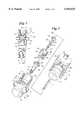
- FIG. 1is an isometric, exploded view, with portions broken away and partially in section, of the implant mount, clamp screw and driver assembly in accordance with the present invention.
- FIG. 2is an elevational, exploded side view, with portions broken away and partially in section, showing the implant mount, clamp screw and driver assembly of the invention.
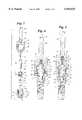
- FIG. 3is an elevational side view, partially in section, of an implant assembly of the present invention.
- FIG. 4is a side elevational view, partially in section, showing the driver assembly in a first position relative to the implant mount.
- FIG. 5is a view similar to that of FIG. 4 showing the driver assembly in a second position relative to the implant mount.
- FIG. 6is a sectional view of the implant mount of the present invention.
- FIG. 7is a side elevational view of the clamp screw.
- FIG. 8is a top elevational view of the clamp screw.
- FIG. 9is a side elevational view, partially in section, of the driver housing.
- FIG. 10is a sectional view of the drive member.
- FIG. 11is a bottom elevational view of the drive member.
- FIG. 12is a top elevational view of the drive member.
- FIG. 13is a side elevational view of the screw removal insert.
- FIG. 14is a side elevational view, partially in section, of a portion of the implant mount showing one of the counter-torque openings and a counter-torque tool.
- FIGS. 1-5illustrate the general structure and operation of the implant mount and driver assembly in accordance with the present invention.
- the structure of the present inventionincludes an implant assembly comprised of an implant mount 10, an implant 11 and a clamp screw 12 and a driver assembly comprised of a split ring 13, a driver housing 14, an associated drive member 15, a screw removal insert 16 and a coil spring 17.
- the spring 17is positioned between the top of the screw removal insert 16 and an interior portion of the driver housing 14.
- the split ring 13is metal, although it is contemplated that it could be constructed of rubber or other material.
- the implant assemblyis normally delivered for use in a pre-mounted position as illustrated in FIG. 3 in which the implant mount 10 is mounted to the implant 11 by the clamp screw 12.
- the implant 11is a conventional component having a hexagonal or other connecting means at its top end and an internally threaded hole for receiving the clamp screw 12 during installation and a cap screw, prothesis or other appliance (not shown) after installation.
- the driver assemblyis connectable with the implant mount 10 so that it is selectively positionable between a first position illustrated in FIG. 4 in which the drive member 15 and thus the driver housing 14 are operatively connected with the implant mount 10 and a second position illustrated in FIG. 5 in which the drive member 15 and driver housing 14 are operatively connected with the screw removal insert 16 and thus the clamp screw 12.
- the implant mount 10includes a lower section 18 having a generally cylindrical exterior configuration.
- the interior of the section 18includes a lower connection section 19 in the form of an internal hexagonal or hex configuration and a through opening 20.
- the internal hexagonal portion 19is adapted for connection with an external hexagonal configuration of the implant 11 (FIGS. 3-5).
- the top section of the implant mount 10includes a sleeve portion 21 having an upper generally cylindrically interior surface 22 and a lower connection surface 24 comprised of an internal hexagonal configuration. As shown, the diametrical dimension of the surface 22 is greater than the largest diametrical dimension of the hexagonal surface 24.
- the generally cylindrical exterior surface of the sleeve 21is provided with first and second positioning means in the form of a first detent or groove 25 and a second detent or groove 26. These grooves 25 and 26 extend circumferencially around the sleeve 21. Positioned between the upper sleeve portion 21 and the lower section 18 is a centrally positioned counter-torque portion 28 having a plurality of radial counter-torque portion 28 having a plurality of radial counter-torque openings 29 about its periphery for applying counter-torque to the implant mount 10 during removal, if desired. An internal surface and shoulder 30 define a cavity to receive the head of the clamp screw 12 and extend between the internal hex configured surface 24 and the opening 20.
- the counter-torque means of the present inventionincludes the plurality of radial openings 29. During use, these openings 29 receive a forward end 23 of a counter-torque tool 27.
- the tool 27comprises a generally cylindrical handle 37 which can be several inches long for manual manipulation.
- the walls 33 of the openings 29taper slightly inwardly toward the center of the mount 10.
- the outer surface of the end 23tapers slightly inwardly toward its end so that it substantially matches the taper of the walls 33. This taper helps retain the implant mount relative to the tool 27 when used.
- the benefits of the counter-torque meanscan be realized independently of other features of the present invention.
- the clamp screw 12includes a lower threaded portion 31, an upper head 32 and a centrally positioned shank 34.
- a hexagonal interior surface 35extends from the top surface of the head 32 to a predetermined depth within the shank 34.
- the threaded portion 31is designed to be received by the internal threads of the implant 11.
- the clamp screw 12functions to secure the implant mount 10 to the implant 11 during installation of the implant.
- FIG. 9illustrates the driver housing 14 which includes a generally cylindrical sleeve section 36 having an open end 38 and an opposite end integrally connected with a hand piece connection shank 39.
- the distal end of the shank 39includes a latch attachment mechanism 40 for connecting the shank 39 and thus the entire driver assembly to a dental hand piece in a manner known in the art.
- the interior of the housing 36includes a plurality of interior cylindrical surfaces 41, 42 and 44. Positioned at the lower end of the surface 41 is an internal groove or recess 45 for receiving a split ring 13 or similar connecting member.
- the internal cylindrical surface 42is adapted for receiving the drive member 16 and the interior surface 44 defines a spring receiving cavity for receiving one end of the coil spring 17 as will be described in greater detail below.
- the drive member 15is a generally cylindrically shaped member having an outer cylindrical surface 48 at its upper end and an outer hexagonally configured surface 49 at its lower end.
- the hexagonal lower end 49is designed for selective insertion into and driving engagement with the internal hexagonal surface 24 of the implant mount 10 (FIG. 6).
- the interior of the drive member 15includes an upper interior cylindrical surface 50 and a lower surface 51 of hexagonal configuration designed to receive and operatively engage the hexagonal end of the screw removal insert 16 as will be described in greater detail below.
- the inner diametrical dimension of the cylindrical surface 50is greater than the greatest diametrical dimension of the hexagonal surface 51. This allows free rotational movement of the head 54 of the screw removal insert 16 within the upper portion 50.
- the outer dimension of the surface 48approximates the inner dimension of the cylindrical surface 42 of the driver housing 14 and is designed for insertion into the cylindrical opening defined by the surface 42 and laser welded or otherwise rigidly secured thereto. This connection between the drive member 15 and the driver housing 14 is accomplished after appropriate insertion of the coil spring 17 and the screw removal insert 16 as described below.
- the screw removal insert 16 as shown in FIG. 13includes a lower portion 52 with an exterior hexagonal configuration, a top head 54 with an exterior hexagonal configuration and a central, cylindrical shank portion 55 between the portion 52 and the head 54.
- the lower end 57 of the hexagonal portion 52is beveled as shown to provide a lead-in surface for the portion 52.
- a raised or dimple portion 56is provided on top of the head 54 for capturing the coil spring 17 when assembled.
- the hexagonal portion 52is designed for insertion into the hexagonal opening 35 in the clamp screw head 34 for operative engagement therewith.
- the driver assemblyWhen fully assembled, the driver assembly is capable of selective positioning between a first or inferior position in which the driver assembly is operatively engaged with the implant mount 10 as shown in FIG. 4 and a second or superior position in which the driver assembly is operatively engaged with the screw removal insert 16 and thus the clamp screw 12 as shown in FIG. 5.
- the screw removal insert 16is positioned relative to the drive member 15 so that the hexagonal portion 52 and shank 55 (FIG. 13) extend through the opening 53 (FIG. 12) and the head 54 is positioned within the area defined by the cylindrical surface 50 or the hexagonal surface 51.
- the coil spring 17is then positioned on top of the head 54 so that it is centered on the raised dimple 56 and the entire assembly is inserted into the driver housing 14 so that the spring 17 is received by the cylindrical spring receiving cavity 44 and the cylindrical upper surface 48 of the drive member 15 is received by the surface 42.
- the member 15is then rigidly secured to the housing 14 via laser welding or the like. The driver assembly is now ready for use.
- the assemblyis connected to a dental hand piece (not shown) and the open end 38 of the housing 14 is positioned over the top end of the implant mount 10 so that the sleeve portion 21 of the implant mount 10 is extends into the cylindrical area defined by the surface 41 of the housing 14.
- This connectionis normally made while the implant assembly comprising the mount 10 and the connected implant 11 are in a package or under sterile conditions.
- the housing 14is preferably moved to its first or inferior position illustrated in FIG. 4 in which the retaining or split ring 13 engages the lower positioning recess 25.
- the hexagonal configured end 49 of the member 15is positioned in operative engagement with the interior hexagonal configured portion 24 of the mount 10 and the hexagonal portion 52 of the screw removal insert 16 is positioned within the hex opening 35 of the clamp screw 12 and is biased into this position by the spring 17. Because of engagement between the bottom end of the insert 16 and the bottom of hexagonal opening 35 and the relative position of the housing 14, and thus the member 15, the head 54 of the insert 16 is in the portion of the member 15 defined by the surface 50.
- the drive member 15is operatively disengaged from the screw removal insert 16 and thus the clamp screw 12.
- the length of the insert 16 from the bottom of the head 54 to the bottom of the lower end 57must be sufficient to position the head 54 in the area defined by the surface 50 when the driver assembly is in its first position.
- the housing 14is moved upwardly relative to the implant mount 10 to its second or superior position as shown in FIG. 5 with the retaining ring 13 positioned in the positioning recess 26.
- the hexagonal end 49is disengaged from the hexagonal surface 24 of the mount 10
- the head 54 of the screw removal insert 16is engaged with the internal hexagonal surface 51 of the member 15.
- the drive assembly and the implant mount 10are operatively disengaged from one another and the drive assembly is operatively engaged with the screw removal insert 16 and thus the clamp screw 12.
- the clamp screw 12is removed from the implant mount 10.
- the entire implant mount 10, the clamp screw 12 and the driver assemblycan then be removed from the patient's mouth.
- a counter-torque tool or member 27(FIGS. 6 in 14) can be inserted into one of the counter-torque openings 29 in the mount 10 to prevent any reverse rotation during removal of the clamp screw 12.
- the mount 10 and the clamp screw 12are captured within the driver assembly via the split ring connector 13.
- the method of the present inventionis a method for installing a dental implant and removing an implant mount and clamp screw with a single tool. More specifically, the method of the present invention includes providing a driver assembly which is selectively connectable for rotating either the implant mount or the clamp screw, selectively connecting the driver assembly to the implant mount for installation of the implant, subsequently selectively connecting the driver assembly to the clamp screw to withdraw the clamp screw and then removing the driver assembly, clamp screw and implant mount from the patient's mouth.
- the implant mount of the preferred embodimentshows an internal hexagonal surface for connection with an external hexagonal surface of the implant.
- the connection between the implant mount and the implantcould be something other than a hex connection.
- the connections between the surfaces 49 and 24, the connections between the head 54 and the surface 51 and the connection between the portion 52 of the insert 16 and the opening 35 of the head 32could be configured other than hexagonal and could comprise other connecting means.
- the driver assemblymust include some element, elements or means which enable the driver assembly to be selectively connectable to either the implant mount or to the clamp screw.
- the present inventioncould include means other than the split ring 13 for connecting the driver assembly to the implant mount and for defining the first and second positions of the driver assembly relative to the amount.
Landscapes
- Health & Medical Sciences (AREA)
- Oral & Maxillofacial Surgery (AREA)
- Orthopedic Medicine & Surgery (AREA)
- Dentistry (AREA)
- Epidemiology (AREA)
- Life Sciences & Earth Sciences (AREA)
- Animal Behavior & Ethology (AREA)
- General Health & Medical Sciences (AREA)
- Public Health (AREA)
- Veterinary Medicine (AREA)
- Dental Prosthetics (AREA)
Abstract
Description
Claims (24)
Priority Applications (1)
| Application Number | Priority Date | Filing Date | Title |
|---|---|---|---|
| US09/036,926US5944525A (en) | 1997-03-11 | 1998-03-09 | Dental implant and method and apparatus for installing the same |
Applications Claiming Priority (2)
| Application Number | Priority Date | Filing Date | Title |
|---|---|---|---|
| US4067597P | 1997-03-11 | 1997-03-11 | |
| US09/036,926US5944525A (en) | 1997-03-11 | 1998-03-09 | Dental implant and method and apparatus for installing the same |
Publications (1)
| Publication Number | Publication Date |
|---|---|
| US5944525Atrue US5944525A (en) | 1999-08-31 |
Family
ID=26713635
Family Applications (1)
| Application Number | Title | Priority Date | Filing Date |
|---|---|---|---|
| US09/036,926Expired - Fee RelatedUS5944525A (en) | 1997-03-11 | 1998-03-09 | Dental implant and method and apparatus for installing the same |
Country Status (1)
| Country | Link |
|---|---|
| US (1) | US5944525A (en) |
Cited By (32)
| Publication number | Priority date | Publication date | Assignee | Title |
|---|---|---|---|---|
| US6206696B1 (en)* | 1999-12-10 | 2001-03-27 | Sulzer Calcitek Inc. | Driver tool for one step implant delivery system |
| US6394809B2 (en)* | 1997-10-03 | 2002-05-28 | Implant Innovations, Inc. | Single-stage implant system |
| US6454567B1 (en)* | 2001-04-23 | 2002-09-24 | Ace Surgical Supply Co., Inc. | Dental implant delivery and drive tool |
| US20020152160A1 (en)* | 2000-02-29 | 2002-10-17 | Terry Allen-Rouman | Online funds transfer method |
| EP1304087A3 (en)* | 2001-10-22 | 2003-09-17 | Dr.-medic-stom./UMF Temeschburg, Herbert Hatzlhoffer | Surgical tool |
| US20030224325A1 (en)* | 2002-06-04 | 2003-12-04 | Ajay Kumar | Dental tool with rententive feature |
| WO2004019807A1 (en)* | 2002-09-02 | 2004-03-11 | Eduardo Anitua Aldecoa | Set of motorised instruments which are used to fix dental implants |
| KR100453726B1 (en)* | 2002-05-18 | 2004-10-26 | (주) 코웰메디 | Structure of a mount driver for operating dental implant |
| KR100453728B1 (en)* | 2002-05-18 | 2004-10-26 | (주) 코웰메디 | Structure of a mount driver for operating dental implant |
| US6827575B1 (en)* | 1999-03-18 | 2004-12-07 | Nobel Biocare Ab | Method, arrangement and use for applying a spacer to an implant by means of a screw |
| ES2235578A1 (en)* | 2002-11-18 | 2005-07-01 | Eduardo Anitua Aldecoa | Motorized instruments set for fixing dental implants, has motorized drills and osteotomes, with conical end, cylindrical segment and top end to house connectors |
| US20060029907A1 (en)* | 2004-08-05 | 2006-02-09 | Straumann Holding Ag | Dental implant system |
| US7179084B1 (en)* | 2005-08-16 | 2007-02-20 | Kometas Athas N | Apparatus and method to remove dental implant |
| US20070105067A1 (en)* | 2004-05-28 | 2007-05-10 | Osamu Hayashi | Prosthesis-fixing structure and prosthesis-fixing method |
| EP1836991A1 (en)* | 2006-03-21 | 2007-09-26 | Mauro Galvan | A device for packaging and handling an Endo-osseous implant |
| KR100788240B1 (en) | 2006-12-04 | 2007-12-27 | 장경삼 | Left Hand Dental Implant Extraction Unit |
| US20080097458A1 (en)* | 2006-09-15 | 2008-04-24 | Zimmer Dental, Inc. | Drive tool for orthopedic screws |
| WO2008073287A3 (en)* | 2006-12-07 | 2008-08-21 | Keystone Dental Inc | Driver and method for fixing a dental implant |
| EP1974680A1 (en)* | 2007-03-26 | 2008-10-01 | Soadco, S.L. | Removable coupling system for motor operated surgical tools |
| US7632095B2 (en) | 2007-08-13 | 2009-12-15 | Biomet 3I, Inc. | Method for forming a dental prosthesis |
| US20100248181A1 (en)* | 2006-12-14 | 2010-09-30 | Egbert Kremer | Arrangement for insertion of implants |
| KR100988306B1 (en)* | 2008-11-11 | 2010-10-18 | 오스템임플란트 주식회사 | Fixture screwdriver |
| US8002547B2 (en) | 2000-01-18 | 2011-08-23 | Biomet 3I Llc | Preparation coping for creating an accurate permanent post to support a final prosthesis and method for creating the same |
| US20120288826A1 (en)* | 2011-05-11 | 2012-11-15 | Fitton Iii Russell P | Dental Implants and Methods for Their Insertion into Patients |
| US20140127645A1 (en)* | 2011-06-30 | 2014-05-08 | Precise Implant Systems E.S. Ltd. | Medical and dental implant package |
| US8727774B1 (en) | 2011-12-23 | 2014-05-20 | Thomas Arendt | Dental implant carrier device and implant carrier device assembly |
| US20150351867A1 (en)* | 2013-01-10 | 2015-12-10 | Straumann Holding Ag | Annular resilient retention member |
| US20160000534A1 (en)* | 2013-03-28 | 2016-01-07 | Dentsply International Inc. | Integrated dental implant component and tool for placement of a dental implant component |
| US20160067016A1 (en)* | 2014-09-04 | 2016-03-10 | Jun Song | Fixture remover for implant |
| US9572638B1 (en) | 2014-06-02 | 2017-02-21 | Lloyd T. Anderson | Impression coping spacer and method of dental casting |
| KR20220149088A (en)* | 2021-04-30 | 2022-11-08 | 주식회사 신흥엠에스티 | Implant Driver for implanting tooth implant |
| DE102023106126A1 (en)* | 2023-03-13 | 2024-09-19 | Andreas Neff | Aid for inserting a dental implant into a jawbone and pre-assembled unit consisting of such an aid and a dental implant |
Citations (12)
| Publication number | Priority date | Publication date | Assignee | Title |
|---|---|---|---|---|
| US4995810A (en)* | 1987-04-22 | 1991-02-26 | Astra Meditec Aktiebolag | Tool for a prosthetic part |
| US5062800A (en)* | 1990-03-21 | 1991-11-05 | Core-Vent Corporation | Dental implant handle, and dental implant package including a dental implant handle |
| US5108288A (en)* | 1991-06-14 | 1992-04-28 | Perry William L | Non-rotational prosthodontic restoration |
| US5145371A (en)* | 1989-09-15 | 1992-09-08 | Nobelpharma Ab | Distance member |
| US5199873A (en)* | 1990-01-15 | 1993-04-06 | Friedrichsfeld Ag Keramik- Und Kunststoffwerke | Dental implant |
| US5322443A (en)* | 1993-02-11 | 1994-06-21 | Implant Innovations, Inc. | Method and means for affixing a component to a dental implant |
| US5538428A (en)* | 1994-04-05 | 1996-07-23 | Attachments International | Packing delivery system for dental implant and method |
| US5582299A (en)* | 1994-03-01 | 1996-12-10 | Implant Innovations, Inc. | Dental implant packaging |
| US5620323A (en)* | 1994-08-22 | 1997-04-15 | Bressman; Robert A. | Dental restoration structure |
| US5692904A (en)* | 1993-02-11 | 1997-12-02 | Implant Innovations, Inc. | Method and means for affixing a component to a dental implant |
| US5702346A (en)* | 1992-03-03 | 1997-12-30 | Implant Innovations Inc | Dental implant fixture for anchorage in cortcal bone |
| US5709547A (en)* | 1992-03-03 | 1998-01-20 | Implant Innovations, Inc. | Dental implant for anchorage in cortical bone |
- 1998
- 1998-03-09USUS09/036,926patent/US5944525A/ennot_activeExpired - Fee Related
Patent Citations (12)
| Publication number | Priority date | Publication date | Assignee | Title |
|---|---|---|---|---|
| US4995810A (en)* | 1987-04-22 | 1991-02-26 | Astra Meditec Aktiebolag | Tool for a prosthetic part |
| US5145371A (en)* | 1989-09-15 | 1992-09-08 | Nobelpharma Ab | Distance member |
| US5199873A (en)* | 1990-01-15 | 1993-04-06 | Friedrichsfeld Ag Keramik- Und Kunststoffwerke | Dental implant |
| US5062800A (en)* | 1990-03-21 | 1991-11-05 | Core-Vent Corporation | Dental implant handle, and dental implant package including a dental implant handle |
| US5108288A (en)* | 1991-06-14 | 1992-04-28 | Perry William L | Non-rotational prosthodontic restoration |
| US5702346A (en)* | 1992-03-03 | 1997-12-30 | Implant Innovations Inc | Dental implant fixture for anchorage in cortcal bone |
| US5709547A (en)* | 1992-03-03 | 1998-01-20 | Implant Innovations, Inc. | Dental implant for anchorage in cortical bone |
| US5322443A (en)* | 1993-02-11 | 1994-06-21 | Implant Innovations, Inc. | Method and means for affixing a component to a dental implant |
| US5692904A (en)* | 1993-02-11 | 1997-12-02 | Implant Innovations, Inc. | Method and means for affixing a component to a dental implant |
| US5582299A (en)* | 1994-03-01 | 1996-12-10 | Implant Innovations, Inc. | Dental implant packaging |
| US5538428A (en)* | 1994-04-05 | 1996-07-23 | Attachments International | Packing delivery system for dental implant and method |
| US5620323A (en)* | 1994-08-22 | 1997-04-15 | Bressman; Robert A. | Dental restoration structure |
Cited By (47)
| Publication number | Priority date | Publication date | Assignee | Title |
|---|---|---|---|---|
| US6394809B2 (en)* | 1997-10-03 | 2002-05-28 | Implant Innovations, Inc. | Single-stage implant system |
| US6827575B1 (en)* | 1999-03-18 | 2004-12-07 | Nobel Biocare Ab | Method, arrangement and use for applying a spacer to an implant by means of a screw |
| US6206696B1 (en)* | 1999-12-10 | 2001-03-27 | Sulzer Calcitek Inc. | Driver tool for one step implant delivery system |
| US8002547B2 (en) | 2000-01-18 | 2011-08-23 | Biomet 3I Llc | Preparation coping for creating an accurate permanent post to support a final prosthesis and method for creating the same |
| US20020152160A1 (en)* | 2000-02-29 | 2002-10-17 | Terry Allen-Rouman | Online funds transfer method |
| US6454567B1 (en)* | 2001-04-23 | 2002-09-24 | Ace Surgical Supply Co., Inc. | Dental implant delivery and drive tool |
| EP1304087A3 (en)* | 2001-10-22 | 2003-09-17 | Dr.-medic-stom./UMF Temeschburg, Herbert Hatzlhoffer | Surgical tool |
| KR100453726B1 (en)* | 2002-05-18 | 2004-10-26 | (주) 코웰메디 | Structure of a mount driver for operating dental implant |
| KR100453728B1 (en)* | 2002-05-18 | 2004-10-26 | (주) 코웰메디 | Structure of a mount driver for operating dental implant |
| US20050266379A1 (en)* | 2002-06-04 | 2005-12-01 | Zimmer Dental Inc. | Dental tool with retentive feature |
| US20030224325A1 (en)* | 2002-06-04 | 2003-12-04 | Ajay Kumar | Dental tool with rententive feature |
| US6951462B2 (en)* | 2002-06-04 | 2005-10-04 | Zimmer Dental Inc. | Dental tool with rententive feature |
| WO2004019807A1 (en)* | 2002-09-02 | 2004-03-11 | Eduardo Anitua Aldecoa | Set of motorised instruments which are used to fix dental implants |
| US20060121415A1 (en)* | 2002-09-02 | 2006-06-08 | Eduardo Anitua Aldecoa | Set of motor-driven instruments to aid the fixing of dental implants |
| US8142190B2 (en) | 2002-09-02 | 2012-03-27 | Biotechnology Institute, I Mas D, S.L. | Set of motor-driven instruments to aid the fixing of dental implants |
| US20100273128A1 (en)* | 2002-09-02 | 2010-10-28 | Eduardo Anitua Aldecoa | Set of motor-driven instruments to aid the fixing of dental implants |
| ES2235578B2 (en)* | 2002-11-18 | 2007-08-16 | Eduardo Anitua Aldecoa | SET OF MANUAL OR MOTORIZED DRIVING INSTRUMENTS TO FACILITATE THE SETTING OF DENTAL IMPLANTS. |
| ES2235578A1 (en)* | 2002-11-18 | 2005-07-01 | Eduardo Anitua Aldecoa | Motorized instruments set for fixing dental implants, has motorized drills and osteotomes, with conical end, cylindrical segment and top end to house connectors |
| US20070105067A1 (en)* | 2004-05-28 | 2007-05-10 | Osamu Hayashi | Prosthesis-fixing structure and prosthesis-fixing method |
| US20060029907A1 (en)* | 2004-08-05 | 2006-02-09 | Straumann Holding Ag | Dental implant system |
| JP2006043453A (en)* | 2004-08-05 | 2006-02-16 | Straumann Holding Ag | Dental implant system |
| US7300284B2 (en)* | 2004-08-05 | 2007-11-27 | Straumann Holding Ag | Dental implant system |
| US7179084B1 (en)* | 2005-08-16 | 2007-02-20 | Kometas Athas N | Apparatus and method to remove dental implant |
| EP1836991A1 (en)* | 2006-03-21 | 2007-09-26 | Mauro Galvan | A device for packaging and handling an Endo-osseous implant |
| US20080097458A1 (en)* | 2006-09-15 | 2008-04-24 | Zimmer Dental, Inc. | Drive tool for orthopedic screws |
| US8771285B2 (en)* | 2006-09-15 | 2014-07-08 | Zimmer Dental, Inc. | Drive tool for orthopedic screws |
| KR100788240B1 (en) | 2006-12-04 | 2007-12-27 | 장경삼 | Left Hand Dental Implant Extraction Unit |
| WO2008073287A3 (en)* | 2006-12-07 | 2008-08-21 | Keystone Dental Inc | Driver and method for fixing a dental implant |
| US9095397B2 (en)* | 2006-12-14 | 2015-08-04 | Friadent Gmbh | Arrangement for insertion of implants |
| US20100248181A1 (en)* | 2006-12-14 | 2010-09-30 | Egbert Kremer | Arrangement for insertion of implants |
| ES2323255B1 (en)* | 2007-03-26 | 2010-04-19 | Soadco, S.L. | ENVIRONMENTAL COUPLING SYSTEM FOR MOTORIZED SURGICAL TOOLS. |
| EP1974680A1 (en)* | 2007-03-26 | 2008-10-01 | Soadco, S.L. | Removable coupling system for motor operated surgical tools |
| ES2323255A1 (en)* | 2007-03-26 | 2009-07-09 | Soadco, S.L. | Removable coupling system for motor operated surgical tools |
| US7632095B2 (en) | 2007-08-13 | 2009-12-15 | Biomet 3I, Inc. | Method for forming a dental prosthesis |
| KR100988306B1 (en)* | 2008-11-11 | 2010-10-18 | 오스템임플란트 주식회사 | Fixture screwdriver |
| US20120288826A1 (en)* | 2011-05-11 | 2012-11-15 | Fitton Iii Russell P | Dental Implants and Methods for Their Insertion into Patients |
| US20140127645A1 (en)* | 2011-06-30 | 2014-05-08 | Precise Implant Systems E.S. Ltd. | Medical and dental implant package |
| US8727774B1 (en) | 2011-12-23 | 2014-05-20 | Thomas Arendt | Dental implant carrier device and implant carrier device assembly |
| US20150351867A1 (en)* | 2013-01-10 | 2015-12-10 | Straumann Holding Ag | Annular resilient retention member |
| US11547529B2 (en)* | 2013-01-10 | 2023-01-10 | Straumann Holding Ag | Annular resilient retention member |
| US20160000534A1 (en)* | 2013-03-28 | 2016-01-07 | Dentsply International Inc. | Integrated dental implant component and tool for placement of a dental implant component |
| US10390910B2 (en)* | 2013-03-28 | 2019-08-27 | Dentsply Sirona Inc. | Integrated dental implant component and tool for placement of a dental implant component |
| US9572638B1 (en) | 2014-06-02 | 2017-02-21 | Lloyd T. Anderson | Impression coping spacer and method of dental casting |
| US20160067016A1 (en)* | 2014-09-04 | 2016-03-10 | Jun Song | Fixture remover for implant |
| US9750583B2 (en)* | 2014-09-04 | 2017-09-05 | Ducksu HUR | Fixture remover for implant |
| KR20220149088A (en)* | 2021-04-30 | 2022-11-08 | 주식회사 신흥엠에스티 | Implant Driver for implanting tooth implant |
| DE102023106126A1 (en)* | 2023-03-13 | 2024-09-19 | Andreas Neff | Aid for inserting a dental implant into a jawbone and pre-assembled unit consisting of such an aid and a dental implant |
Similar Documents
| Publication | Publication Date | Title |
|---|---|---|
| US5944525A (en) | Dental implant and method and apparatus for installing the same | |
| EP0748188B1 (en) | Means for affixing a component to a dental implant | |
| US6786725B2 (en) | Dental implant and tool and method for effecting a dental restoration using the same | |
| US5322443A (en) | Method and means for affixing a component to a dental implant | |
| US5437550A (en) | Method and means for affixing a component to a dental implant | |
| US6168436B1 (en) | Universal dental implant abutment system | |
| KR100698564B1 (en) | Prosthesis mounting device | |
| EP1474063B1 (en) | Dental implant delivery system | |
| US8087935B2 (en) | Implant delivery system | |
| EP0376944B1 (en) | A tool for a prosthetic part | |
| JP4278388B2 (en) | Device for operating an implant | |
| US20190021822A1 (en) | Dental implant system | |
| US5890902A (en) | Implant bone locking mechanism and artificial periodontal ligament system | |
| US5462436A (en) | Method and means for affixing a component to a dental implant | |
| CA2405093C (en) | Implant | |
| US5413480A (en) | Overdenture attachment system | |
| KR20000067899A (en) | Abutment-mount system for dental implants | |
| KR20070103086A (en) | Prosthetic Mounting Devices and Assemblies | |
| CA2699030A1 (en) | Pick-up implant abutment and method | |
| US6203323B1 (en) | Implant delivery system | |
| KR200255069Y1 (en) | Dental Screw Driving Tools | |
| KR101181924B1 (en) | Implant operation tool | |
| WO1998040029A1 (en) | Dental implant and method and apparatus for installing the same | |
| US20250127594A1 (en) | Devices, instruments, systems, and methods for preparing prostheses | |
| EP3866727B1 (en) | Tool for use in dental implant treatments and retention element |
Legal Events
| Date | Code | Title | Description |
|---|---|---|---|
| FPAY | Fee payment | Year of fee payment:4 | |
| REMI | Maintenance fee reminder mailed | ||
| LAPS | Lapse for failure to pay maintenance fees | ||
| STCH | Information on status: patent discontinuation | Free format text:PATENT EXPIRED DUE TO NONPAYMENT OF MAINTENANCE FEES UNDER 37 CFR 1.362 | |
| FP | Expired due to failure to pay maintenance fee | Effective date:20070831 | |
| AS | Assignment | Owner name:SUNTRUST BANK, GEORGIA Free format text:SECURITY AGREEMENT;ASSIGNORS:EXACTECH, INC.;ALTIVA, LLC;BRIGHTON PARTNERS, LLC;AND OTHERS;REEL/FRAME:027779/0053 Effective date:20120224 | |
| AS | Assignment | Owner name:EXACTECH INTERNATIONAL, LLC, FLORIDA Free format text:RELEASE BY SECURED PARTY;ASSIGNOR:SUNTRUST BANK, AS ADMINISTRATIVE AGENT;REEL/FRAME:037358/0511 Effective date:20151217 Owner name:ALTIVA, LLC, FLORIDA Free format text:RELEASE BY SECURED PARTY;ASSIGNOR:SUNTRUST BANK, AS ADMINISTRATIVE AGENT;REEL/FRAME:037358/0511 Effective date:20151217 Owner name:BRIGHTON PARTNERS, LLC, FLORIDA Free format text:RELEASE BY SECURED PARTY;ASSIGNOR:SUNTRUST BANK, AS ADMINISTRATIVE AGENT;REEL/FRAME:037358/0511 Effective date:20151217 Owner name:EXACTECH, INC., FLORIDA Free format text:RELEASE BY SECURED PARTY;ASSIGNOR:SUNTRUST BANK, AS ADMINISTRATIVE AGENT;REEL/FRAME:037358/0511 Effective date:20151217 |